NOVA1无线接收机
常见数字卫星接收机盲扫密码大全

常见数字卫星接收机盲扫密码大全阿瓦斯2001机器的密码:1577九州DVC-2008IR的初始密码:9949航科系列机器密码:6931ap6-84卡密码:xx96均可诺基亚8800初始密码9949AP6-84卡的密码:凡带96就可!就连光输入96都可以!国产富事通机器:上。
下。
左。
右VISTAR2000密码1234新闻台(3、5、6、8)专用机DY2000S:上。
下。
左。
右帝霸901工程密码:1001帝霸901密码:0000百胜p-3900机器密码:1111Simon 920 初始密码1234 统吃码3453创维DVB-SO1的工程密码是:13572468RCA-993S:6931v2.4blocker卡成人密码:9996PBI 8888天域1001金泰克小神童盲扫及删除频道密码:54321P-3880缺省密码:0000。
万能密码:98763500的恢复原始:同时按前面版OK跟频道上两键,密码初次为0000。
v2.4blocker卡成人密码:9996阿瓦斯2001机器的密码:1577九州DVC-2008IR的初始密码:9949航科系列机器密码:6931ap6-84卡密码:xx96均可诺基亚8800初始密码9949AP6-84卡的密码:凡带96就可!输入96也可以!国产富事通机器:上.下.左.右VISTAR2000密码1234新闻台(3、5、6、8)专用机DY2000S:上.下.左.右帝霸901工程密码:1001百胜p-3900机器密码:1111Simon 920 初始密码1234 统吃码3453帝霸901密码:0000PANDA-610:家长码:0000系统码:9317。
开机前用手指分别按住面板上第一个和第三个键,加电后约一分钟,松开,用系统恢复菜单恢复系统即可。
同洲981(工程机)接收机的初始密码:依次输入上下左右海克威6688,海克威5688盲扫密码:1270创维的高级用户的开启密码:135724682300机密码和百胜双片机的一样:1111PBI1000恢复系统密码:8888430的父母锁原始密码:1234。
NovAtel OEMV1接收板中文彩页

OEMV-1
性能1
接收通道配置(最多 36 通道) 14 GPS L1 2 SBAS 1 L-Band
定位精度
L1
1.8m CEP
DGPS
0.45m CEP
WAAS
1.2m CEP
OminiSTAR VBS 1.0m CEP
CDGPS RT-202
0.7m CEP 0.2m CEP
观测量精度 L1 C/A 码 L1 载波相位
6 cm RMS 0.75mm RMS
数据更新率3 观测量 位置解算
20 Hz 20 Hz
首次定位时间
冷启动4
50s
温启动5
40s
热启动6
30s
信号重捕获
L1 授时精度7
0.5s(典型值) 20 ns RMS
测速精度 0.03 m/s RMS
动态指标 速度8 高度8
515 m/s 18,288 m
物理尺寸和电气特性
OEMV 的 ASIC 集成了接收 L 波段信号的功能以节省用户的硬件开销。OEMV-1 板卡 在最小化用户终端设备的尺寸、成本和复杂性的条件下,能帮助用户获取 OminSTAR VBS 或者 CDGPS 改正数据达到亚米级的精度。在 L-band 定位的主板市场,OEMV-1 是市场上唯 一支持板级 L-band 功能的 L1 板卡。 贴近用户应用的 API 功能
步的可控 PPS 输出和标记脉冲输入 具备驱动外部 LED 指示灯的输出
1 典型值。性能指标会随着 GPS 的系统特性、U.S.国防部的控制方式、电离层与对流层的变化以及卫星分 布、基线长度、多路径影响以及人为或自然的干扰而变化
2 静态收敛后的预期值 3 对于 API 用户数据更新率可能会降低。最快的数据更新率取决于应用函数占用的资源 4 典型值。无历书和星历并且没有概略位置与时间 5 典型值。有存储的历书及概略位置与时间,无近期的星历 6 典型值。有历书、近期星历与概略位置与时间 7 时间精度不含由于天线与线缆引入的偏移 8 出口限制规定最大高度为 18,288 米,速度为 514 米/ 秒 9 需要外接 CAN 发送器和用户应用软件
华为AAU系列产品说明 (version_1)

AAU系列产品说明书Huawei Technologies Co., Ltd.All rights reserved目录一、基本概念 (3)1.1什么是AAS? (3)1.2有源天线介绍 (4)1.2.1有源天线(Active Antenna)和无源天线(Passive Antenna)有什么区别? (4)1.2.2有源天线(AAU)是基站形态未来演进的主要方向 (4)1.3AAU产品宣传的规格中1A+1P,A和P是什么含义? (4)二、AAU产品介绍 (5)2.1AAU3210 (5)2.2AAU3213 (7)2.3AAU3240 (9)2.4AAU3910 (10)2.5AAU3911 (12)2.6AAU3920 (15)2.7AAU3940 (16)3AAU产品FAQ (18)3.1AAU的解决方案场景? (18)3.2我们的AAU3910和AAU3920都支持1.8GHz+2.1GHz的配置,如何选择? (18)3.3AAU能否支持外接友商的RRU或者宏基站,有何限制? (18)3.4AAU3910和AAU3911区别 (18)3.5AAU3910和AAU3913区别 (19)四参数规格 (20)一、基本概念1.1什么是AAS?AAS(Active Antenna System)有源天线系统是继RFU、RRU之后衍生出的一种新的射频模块形态。
RRU的功能上移,与天线的功能合并,通过射频多通道技术对天线垂直方向阵子阵列和水平方向阵子阵列进行控制,灵活的控制天线在垂直和水平方向的波束,通过不同波束赋形的方式可以达到改善无线信号的覆盖质量提升网络容量的目的。
当前,业界有4种类型的AAS技术,满足不同的运营商需求:•SAAS (Simple AAS):简单集成的AAS,将RRU与天线简单集成,主要用来简化天面。
产品不对天线的波束进行控制,只能调整倾角,如华为AAU3910/3911/3920系列产品和爱立信的AIR产品。
各类卫星电视接收机密码大全(绝对实用)
十五、CDVB
38 CDVB2000E:自行设4位数。
十六、C-5880
15、科林、诺普斯:菜单→扩展菜单→OK→系统设定→OK→系统2→OK→音量减4次→静音即可。
四、德州科海
16、德州科海5088:系统恢复:按左键→下键→下键→下键→左键→下键→再按下键两次。
39、C-5880:key修改进入密码:0000;万能码:9876。
十七、V2.4BLOCKER卡
40、V2.4BLOCKER卡成人密码:9996。
三、科林
13、科林:(1)在安装设定,电源选择时按5次“1”键。(2)在“恢复出厂”时,按5次“1”键可恢复所有出厂预置节目。
14、科林K2838、KL-3383R:“搜索”菜单转到“转发器设置”,按音量减键4次,再按静音键即可。
八、天诚
23、天诚机器密码:1001。
九、金泰克
24、金泰克小神童盲扫及删除频道密码:“菜单”→输入密码:54321。
33、P3500的恢复原始设置:同时按前面板OK和频道上两键,密码初次为:0000。
十二、E
27、金泰克大丰收D8000:菜单→节目设置“54321”(或“082004)即可。
28、金泰克:菜单直接输入54321或者5678。
十、喜洋洋
各类卫星电视接收机密码大全(绝对实用)
卫星电视接收机现已进入每个家庭,通常都是被广电部门一次设定后使用,现转载一篇介绍各类卫星电视接收机的密码进入方法,非常实用。66种134款卫星电视接收机密码进入方法供你参考。
一、皇视
五、科海
17、科海5088:系统设定1,按左键一次、下键一次、再按左键一次、按下键二次。
Arctis Nova 1 产品信息指南说明书

ARCTIS NOVA 1 PRODUCT INFORMATION GUIDETABLE OF CONTENTSGeneral . . . . . . . . . . . . . . . . . . . . . . . . . . . . . . . . . . . . . . . . . . . . . . . . . . 3 Product Overview . . . . . . . . . . . . . . . . . . . . . . . . . . . . . . . . . . . . . . . . . 4 Setup . . . . . . . . . . . . . . . . . . . . . . . . . . . . . . . . . . . . . . . . . . . . . . . . . . . 5 Microphone . . . . . . . . . . . . . . . . . . . . . . . . . . . . . . . . . . . . . . . . . . . . . . 6 Perfect Fit . . . . . . . . . . . . . . . . . . . . . . . . . . . . . . . . . . . . . . . . . . . . . . . 7 Regulatory . . . . . . . . . . . . . . . . . . . . . . . . . . . . . . . . . . . . . . . . . . . . . . . 8GENERALPACKAGE CONTENTSArctis Nova 1 HeadsetMain Headset CableDual 3 .5 mm Extension CableSYSTEM COMPATIBILITYPCXboxPlayStation 5PlayStation 4Nintendo SwitchSOFTWAREUse Engine inside SteelSeries GG to set customequalizer settings and control your mic .GG also has other amazing apps like Sonar, a breakthroughin gaming sound, that allows you to hear what mattersmost, through cutting-edge audio tools .DOWNLOAD NOWsteelseri.es/gg34PRODUCT OVERVIEWHEADSET1Elastic Headband 2Airweave Ear Cushions*3Retractable ClearCast Microphone 4Volume Wheel 5Microphone Mute Button 6 3 .5 mm Audio JackACCESSORIES*7Main Audio Cable 8 Dual 3 .5 mm Extension Cable*Find accessories and replacement parts at steelseries .com/gaming-accessoriesSETUPSINGLE 3.5 MM CONNECTIONSDUAL 3.5 MM CONNECTIONS56MICROPHONERETRACTABLE MICROPHONEOut of the box, the Retractable ClearCast Microphone (3) is retracted . To use the microphone, slide it away from the headset until it reaches full extension .POSITIONINGPosition the Retractable ClearCast Microphone (3) close to the corner of your mouth with the front surface facing you . Note:The microphone should not be used when retracted .PERFECT FITThere are two ways to adjust the fit of your headset1 Slide the Earcups up or down to change the overall height .2 Change the position of the Elastic Headband (1) on one or bothsides to achieve the desired tension and flex .7REGULATORYEurope – EU Declaration of ConformityHereby, SteelSeries ApS. declares that the equipment which is compliance with directive RoHS2.0 (2015/863/EU), EMC Directive (2014/30/EU), and LVD (2014/35/EU) which are issuedby the Commission of the European Community.The full text of the EU declaration of conformity is available at the following internet address: https:///SteelSeries ApS. hereby confirms, to date, based on the feedback from our suppliers indicates that our products shipping to the EU territory comply with REACH (Registration, Evaluation, Authorization, and Restriction of Chemicals - (EC) 1907/2006) compliance program. We are fully committed to offering REACH compliance on the products and posting accurate REACH compliance status for the all of products.UK Declaration of ConformityHereby, SteelSeries ApS. declares that the following equipment which is compliance with Electromagnetic Compatibility Regulations 2016, Electrical Equipment (Safety) Regulations 2016, Radio Equipment Regulations 2017 and The Restriction of the Use of Certain Hazardous Substances in Electrical and Electronic Equipment Regulations 2012 issued by the Department for Business, Energy& Industrial Strategy.The full text of the UK declaration of conformity is available at the following internet address: WEEEThis product must not be disposed of with your other household waste or treat them in compliance with the local regulations or contact your local city office, your household waste disposal service or the shop where you purchased the product.Federal Communication Commission Interference StatementThis device complies with Part 15 of the FCC Rules. Operation is subject to the following two conditions:This device may not cause harmful interference, andthis device must accept any interference received, including interference that may cause undesired operation.This equipment has been tested and found to comply with the limits for a Class B digital device, pursuant to Part 15 of the FCC Rules. These limits are designed to provide reasonable 8protection against harmful interference in a residential installation. This equipment generates, uses and can radiate radio frequency energy and, if not installed and used in accordance withthe instructions, may cause harmful interference to radio communications. However, there isno guarantee that interference will not occur in a particular installation. If this equipment does cause harmful interference to radio or television reception, which can be determined by turningthe equipment off and on, the user is encouraged to try to correct the interference by one ofthe following measures:Reorient or relocate the receiving antenna.Increase the separation between the equipment and receiver.Connect the equipment into an outlet on a circuit different from that to which the receiveris connected.Consult the dealer or an experienced radio/TV technician for help.FCC Caution:Any changes or modifications not expressly approved by the party responsible for compliance could void the user’s authority to operate this equipment.This transmitter must not be co-located or operating in conjunction with any other antennaor transmitter.Industry Canada StatementThis device complies with Industry Canada license-exempt RSS standard(s). Operation is subjectto the following two conditions:this device may not cause interference, andthis device must accept any interference, including interference that may cause undesired operation of the device.Le présent appareil est conforme aux CNR d’Industrie Canadaapplicables aux appareils radio exempts de licence. L’exploitation est autorisée aux deux conditions suivantes:l’appareil ne doit pas produire de brouillage, etl’utilisateur de l’appareil doit accepter tout brouillage radioélectrique subi, même si le brouillageest susceptible d’en compromettre le fonctionnement.This Class B digital apparatus complies with Canadian ICES-003.Cet appareil numérique de la classe B est conforme à la norme NMB-003 du Canada.该电子电气产品含有某些有害物质,在环保使用期限内可以放心使用,超过环保使用期限之后则应该进入回收循环系统。
卫星接收机
卫星接收机2卫星接收机简介IRD有模拟卫星接收机和数字卫星接收机两种;模拟卫星接收机主要由高频调谐器、中频放大器、限幅器、鉴频器、去加重电路、音视频放大器等组成;数字卫星接收机由高频调谐器、QPSK解调器、前向纠错(FEC)器、解复用器、音视频解码器、D/A转换器等组成;其功能是接收卫星下行经QPSK调制的MPEG-2数据流,并解码出音、视频信号或数据。
卫星接收机的英文Intergrated ReceiverDecoder卫星接收机的分类卫星接收机的种类很多,可分为模拟卫星接收机、数字卫星接收机和多功能卫星接收机,此外还有数字卫星接收卡(盒)。
模拟卫星接收机是早期为接收卫星上发射的模拟节目而设计的,如东芝TSR—C4工程机、松下TU一BS207型BS卫星专用机等。
最早的卫星电视传输的是模拟信号,但模拟信号容易受到干扰,造成图像质量下降;同时模拟信号对频带资源利用率低,一颗卫星传送的模拟节目数量有限;而采用数字压缩信号则能弥补这些缺陷。
随着数字编解码技术的进步,采用模拟信号的接收方式已逐步被数字方式所取代,目前国内仅134.0。
E(哑太6号)还保留一些省台的模拟卫星电视信号。
广播电视节目根据其播出性质有两种:一一种足不加密的免费节目,称为FTA(Free To Air),它一般是政府、宗教团体等开办的具有公益、宣传广告性质的节目,其维持费用是通过其他途径获得的,收视者只需免费接收机(FTA)即可收看。
另一种是加密的节目,即有条件收视CA(Conditional ACCess),一般是节目运营商以盈利为目的,收视者需要付费购买收视卡,配合条件接收机方能收看。
1.免费接收机(FTA)免费接收机只能收免费的卫视节目,加密频道收不到,它是最常见的一种接收机。
免费接收机的品牌、型号很多,常见的如同洲CDVB3188C、海克威HIC-5688、卓异ZY5518E等。
2.条件接收机条件接收机就是为接收加密节目而设计的,电视节目的加密系统有很多,目前主要的有:法国电信公司的ViaCCess(维莎)系统、荷兰爱迪德公司的Irdeto(爱迪德)系统、Telerlor公司的Cotlax(康耐思)系统、法国的Mediaguard-SECA系统、NewsDataCom公司的Newsdatacom系统、飞利浦公司的Cryptoworks系统、美国科学亚特兰大公司的Powerkey系统,此外还有NDS(恩迪斯)系统、Nagravision(南瓜)系统等等。
Sensata IWR-1单频道无线接收器说明书

Page 1OB SO L E T E| IWR-1SINGLE CHANNEL WIRELESS RECEIVERSPECIFICATIONSThe IWR-1 is a single channel receiver designed to pair with any of the Sensata range of IWT wireless transmitters to form a cost-effective replacement of traditional wired transducers. This offers a low cost solution to inaccessible or expensive installation environment. The receiver has a user selectable voltage or mA output corresponding to the calibrated range of the remote Wireless Transducer and 5A rated changeover contacts for alarm functionality.User configuration is possible, however the single channel transmitter/receiver combination is designed to work ‘out of the box’ offering a simple plug and play solution to remote measurement applications. With the standard 0dBI antenna, a line-of-sight range of up to 500 m can be achieved and, using the optional 3dBI antenna, up to 750m (LOS) is achievable.Electrical ProtectionFeatures• Pairs with the IWT range of wireless transmitters • User-selectable 1-5V or 4-20 mA receiver output • Clean contact output for process, low battery or loss of signal alarm function• Simple DIL switch pairing with the IWT transmitters • Up to 500 m range, line-of-sight • 12 to 32 V dc powered• End-to-end accuracy of ±0.25% FS BFSL • LED indication of wireless link• DIN rail or wall mounting kits available• Five channel receiver available - see data sheet IWR-5**Consult relevant IWT Installation manual and data sheet for set-up of alternative transmission rates.Page 2EDIMENSIONSAll dimensions are in millimeters.System Performance (@ +20°C)Temperature Ratings*End-to-end zero tare function available, see user manual.Instrument Power SourceReceiver Input*Compliant with EN 300 328, V1.8.1Enclosure Specifications*Other materials on request.**Consult Installation Manual to ensure adequate signal path between transmitter and receiver.Page 3CONTACT USEUROPE+44 (0)1202 897969*********************Cynergy3 Components Ltd.7 Cobham Road,Ferndown Industrial Estate,Wimborne, Dorset,BH21 7PE, United Kingdom USA+1 310 561 8092 / +1 866 258 5057*********************Sensata Technologies, Inc. (“Sensata”) data sheets are solely intended to assist designers (“Buyers”) who are developing systems that incorporate Sensata products (also referred to herein as “components”). Buyer understands and agrees that Buyer remains responsible for using its independent analysis, valuation, and judgment in designing Buyer’s systems and products. Sensata data sheets have been created using standard laboratory conditions and engineering practices. Sensata has not conducted any testing other than that specifically described in the published documentation for a particular data sheet. Sensata may make corrections, enhancements, improvements, and other changes to its data sheets or components without notice.Buyers are authorized to use Sensata data sheets with the Sensata component(s) identified in each particular data sheet. HOWEVER, NO OTHER LICENSE, EXPRESS OR IMPLIED, BY ESTOPPEL OTHERWISE TO ANY OTHER SENSATA INTELLECTUAL PROPERTY RIGHT, AND NO LICENSE TO ANY THIRD PARTY TECHNOLOGY OR INTELLECTUAL PROPERTY RIGHT, IS GRANTED HEREIN. SENSATA DATA SHEETS ARE PROVIDED “AS IS”. SENSATA MAKES NO WARRANTIES OR REPRESENTATIONS WITH REGARD TO THE DATA SHEETS OR USE OF THE DATA SHEETS, EXPRESS, IMPLIED, OR STATUTORY, INCLUDING ACCURACY OR COMPLETENESS. SENSATA DISCLAIMS ANY WARRANTY OF TITLE AND ANY IMPLIED WARRANTIES OF MERCHANTABILITY, FITNESS FOR A PARTICULAR PURPOSE, QUIET ENJOYMENT, QUIET POSSESSION, AND NON-INFRINGEMENT OF ANY THIRD PARTY INTELLECTUAL PROPERTY RIGHTS WITH REGARD TO SENSATA DATA SHEETS OR USE THEREOF.All products are sold subject to Sensata’s terms and conditions of sale supplied at SENSATA ASSUMES NOLIABILITY FOR APPLICATIONS ASSISTANCE OR THE DESIGN OF BUYERS’ PRODUCTS. BUYER ACKNOWLEDGES AND AGREES THAT IT IS SOLELY RESPONSIBLE FOR COMPLIANCE WITH ALL LEGAL, REGULATORY, AND SAFETY-RELATED REQUIREMENTS CONCERNING ITS PRODUCTS, AND ANY USE OF SENSATA COMPONENTS IN ITS APPLICATIONS, NOTWITHSTANDING ANY APPLICATIONS-RELATED INFORMATION OR SUPPORT THAT MAY BE PROVIDED BY SENSATA.Mailing Address: Sensata Technologies, Inc., 529 Pleasant Street, Attleboro, MA 02703, USAOB SOL EORDERING OPTIONSMade in the UK*Free download user configuration software。
卫星接收机恢复默认出厂设置方法
恢复远程教育卫星接收机出厂参数的设置方法由于目前部分安装远程教育卫星接收机的用户将接收机的参数设置混乱,而不能正常收看到国珍远程电视节目,我们建议用户用恢复出厂默认设置的办法,重新对接收机进行参数配置。
具体方法如下:1、打开接收机电源2、按遥控器上的【Info】键两次,看该菜单显示的状态是否符合如下情况:●菜单的第一行Channel后面的数字是否是新时代所在的频道;●菜单的第二行Satellite 后面显示的是Ku-Telstar-18;●菜单的第三行Transponder 后面的数据必须是12443/H/1500;●菜单的第四行PID后面显示的内容,用户不用考虑。
●菜单的第五行Signal intensity 显示有蓝条的百分号信号强度●菜单的第六行Signal Quality 显示有绿条的百分号信号质量如果你的卫星接收机该菜单符合以上内容,则继续下面的操作步骤;如果不符合以上情况,停止下面的操作步骤;请电话咨询有可能存在的问题。
3、按遥控器上的【MENU】按钮,左侧菜单自上而下显示6个图标:第一个图标为:Edit Channel 菜单项第二个图标为:Installation 菜单项第三个图标为:System setup 菜单项第四个图标为:Tools 菜单项第五个图标为:Games 菜单项第六个图标为:REC 菜单项注:菜单项的名称分别显示在该菜单的顶部中间位置。
4、按遥控器上的方向键【向上/向下】键,选中第四个图标,按遥控器上的方向键【右】键,按遥控器上的方向键【向上/向下】键,选中Factory Setting 选项,再按遥控器上的方向键【右】键,选中Yes选项,再按遥控器上的方向键中间的按钮【OK】键,恢复默认出厂设置完成。
5、关闭接收机电源。
卫星接收机参数的配置方法在完成以上恢复默认出厂设置的情况下,进行如下配置接收机的参数1、打开接收机电源2、按遥控器上的【MENU】按钮,左侧菜单自上而下显示6个图标:第一个图标为:Edit Channel 菜单项第二个图标为:Installation 菜单项第三个图标为:System setup 菜单项第四个图标为:Tools 菜单项第五个图标为:Games 菜单项第六个图标为:REC 菜单项注:菜单项的名称分别显示在该菜单的顶部中间位置。
DL-V3单频接收机使用设置

DL-V3单频接收机使用手册一、前言感谢您购买北斗星通公司的NovAtel产品。
NovAtel DL-V3接收机是一款高性能、高精度和高数据更新率的GPS接收机,使用该类型的接收机进行测量时,不需要另配的数据记录器来记录测量数据,它本身就带有数据存储卡(CF卡)。
DL-V3接收机有多种型号,如单频机、双频机及可以用于RTK测量的接收机。
它将高性能的微处理器和微脉冲相关技术(PAC)相结合,从而使得DL-V3接收机能够更有效地削弱多路径效应的影响。
该类产品具有快速捕获和重捕获GPS 卫星信号的能力,因此,DL-V3接收机能够较好地应用于动态和信号经常中断的环境中。
从DL-V3接收机的功能来说,它可以应用于许多领域——如测量、飞行检查、水利测量、挖掘、摄影测量、农业应用、GIS和差分参考站应用等等。
本手册以简短的语句,提供给您较广泛的知识层面,关于该产品详细的介绍,请参阅随机附送的英文资料。
二、硬件连接1.将GPS天线放在安全、平稳 ,对天空无遮挡的地方.2.旋转插槽挡板上的旋扣打开挡板,将CF卡对准插槽后插入DL-V3前面板.3.使用天线电缆将GPS天线连接到DL-V3接收机后面板的GPS天线端口.4.使用串口电缆连接接收机的COM1口和PC机的串口.5.连接电源电缆,注意接收机PWR端口上的红色标记要与电缆连接器上的红色标记相对应.6.连接如图所示,确认所有线缆连接正确后,给接收机通电。
7.上电并按下开关,电源指示灯显示绿色表示设备电源工作正常。
三、接收机说明1.前面板说明(1)电源指示灯:当显示绿色时,表示接收机电源工作正常。
(2)状态指示灯:接收机刚启动时,闪橙色;当接收机通过硬件自检正常工作后,此灯就灭了。
在接收机工作过程中,如果遇见硬件故障,此灯再次闪橙色。
(3)、串口指示灯:发送数据显示时闪绿色,接收数据时闪黄色。
(4)蓝牙指示灯:当接收机的COM3口处于蓝牙模式时,此灯闪蓝色。
(5)以太网指示灯:当接收机的COM3口处于以太网模式时,此灯闪橙色。
卫星电视接收终端安装使用教程大全(含彩图)
华为AAU系列产品说明 (version_1)

AAU系列产品说明书Huawei Technologies Co., Ltd.All rights reserved目录一、基本概念 (3)1.1什么是AAS? (3)1.2有源天线介绍 (4)1.2.1有源天线(Active Antenna)和无源天线(Passive Antenna)有什么区别? (4)1.2.2有源天线(AAU)是基站形态未来演进的主要方向 (4)1.3AAU产品宣传的规格中1A+1P,A和P是什么含义? (4)二、AAU产品介绍 (5)2.1AAU3210 (5)2.2AAU3213 (7)2.3AAU3240 (9)2.4AAU3910 (10)2.5AAU3911 (12)2.6AAU3920 (15)2.7AAU3940 (16)3AAU产品FAQ (18)3.1AAU的解决方案场景? (18)3.2我们的AAU3910和AAU3920都支持1.8GHz+2.1GHz的配置,如何选择? (18)3.3AAU能否支持外接友商的RRU或者宏基站,有何限制? (18)3.4AAU3910和AAU3911区别 (18)3.5AAU3910和AAU3913区别 (19)四参数规格 (20)一、基本概念1.1什么是AAS?AAS(Active Antenna System)有源天线系统是继RFU、RRU之后衍生出的一种新的射频模块形态。
RRU的功能上移,与天线的功能合并,通过射频多通道技术对天线垂直方向阵子阵列和水平方向阵子阵列进行控制,灵活的控制天线在垂直和水平方向的波束,通过不同波束赋形的方式可以达到改善无线信号的覆盖质量提升网络容量的目的。
当前,业界有4种类型的AAS技术,满足不同的运营商需求:•SAAS (Simple AAS):简单集成的AAS,将RRU与天线简单集成,主要用来简化天面。
产品不对天线的波束进行控制,只能调整倾角,如华为AAU3910/3911/3920系列产品和爱立信的AIR产品。
NOVA HELIX 接收器安装手册说明书
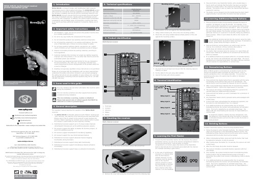
1. Remove the cover from the enclosure using a flat screwdriver .Use a 6mm drill bit to open the required cable entry hole.Centurion Systems (Pty) Ltd 14532Mounting surfaceDrill bitCable saddleCable19. Output Configuration18. Non-Volatile Latches (Sticky Latches)Link Learning is the learning process associated with fitting a plastic link over the J1 pin and the common (middle) pin on the receiver in order to learn remote buttons into memory. Learning buttons using this method will also grant buttons master privileges. There are two primary types of erase that pertain to all the receiver variants:• Transmitter Memory Erase • Settings Memory EraseThe procedure to perform the erase operation is documented below:.1. Start with the receiver powered up.2. If a particular channel compartment must be erased (in otherwords, if all the remote buttons associated with a particular channel must be erased), then fit the channel jumpers that select the desired channel.3. If the entire memory must be erased (or the Settings Memory mustIf a button has been demastered, it can be remastered. There are two methods to achieve this, namely:Link Learn Remastering1. To remaster a remote, start by entering Link Learn Mode. Forreference follow steps 1 and 2 in the Link Learning section 2. To remaster buttons associated with a specific channel, fit thechannel jumper links for that channel. With links fitted, only buttons associated with a selected channel can be remastered. All other buttons will register on the receiver , but will not be processed.Bulk DemasteringSince all remotes that are added to a receiver are always added with master privileges, the HELIX offers users a facility whereby certaingroups of remotes, currently learnt into the receiver , can be demastered simultaneously. This is an important feature since having multiple mas-ters might at times be considered a security risk.To bulk demaster remotes, follow the procedure highlighted below:1. Ensure that there is no power on the receiver .Channel settings modify the way a receiver output responds when it is activated. The output can be configured to act as a latching output, a panic output or any combination thereof. A latching output provides the required drive logic for alarm or equivalent output functionality. Every button transaction associated with a latching output will toggle the current output state of the channel.In the case of multichannel receivers, channel settings are set on an output by output basis. To select a particular output, link the relevant output jumpers (channel jumpers). For example: To set output 1, place a link on channel jumper C1 only. To set channel 11 (a SS II device output), place links on channel jumpers C1, C2 and C4 (the binary combination of C1, C2, and C4 that results in 11 - b’1011’).Proceed as per the steps below to set the required output configuration for the specified output.1. Power down the receiver , and link the relevant channel jumpers toconfigure the respective receiver outputs. On multichannel variants, if no channel is specified via the channel jumpers, the system will not enter channel configuration mode.2. Link jumper J2, and power-up the receiver .3. After the firmware version number has flashed on the Status LED, thebuzzer will provide three short beeps to acknowledge the fact that the receiver is powering up in channel configuration mode.It is possible to disable the functionality associated with jumpers J1 and J2. Receivers are often placed in elevated environments to optimise the range of the receiver . Often, little or no attention is paid to securing the receiver . If the receiver unit is not secured it is possible for a perpetrator to access the jumpers on the receiver and learn a remote into the system without the knowledge or consent of the user . the HELIX range includes functionality to disable the jumpers. With a master remote, the jumpers may be re-enabled at any stage.The following procedure documents disabling the jumper interface on the HELIX range of receivers.1. At least one master transmitter must be learned into the receivermemory.2. Press and hold a master button for between 20 and 30 seconds. Thiswill cause the receiver to enter demastering mode; a single beep at 10 seconds must be ignored, and the button can be released upon hearing a long double beep after 20 seconds.3. While in this mode, fit the link between J2 and the middle pin. TheStatus LED will remain on as long as the pins are bridged.4. When jumper J2 is removed, both jumpers will be disabled and nofurther jumper operations may be performed.To re-enable the jumper interface, repeat steps 1 through 4 again.For further information and programming instructions pertaining to the various advanced features found on Helix receivers, please refer to the appropriate sections in the Helix Full Installation Manual, downloadable from our website .This is a special feature on all receiver variants that allows the receiver to restore its output state on power loss. When power is restored, the output will assume the state it last reflected prior to the receiver los -ing power . Normally a receiver that has latched channels will alwayspower-up with the channels unlatched; regardless of the output state of the channel prior to power loss. The sticky latch feature addresses this problem (in applications where it is seen as a problem), and restores the output state of the latch to its state prior to power-loss.system is not in Bulk Demaster Mode. Either because jumper J1 was not linked correctly before power-up, or because there are no buttons learnt into memory (or associated with the channel selected by the channel jumpers).5. To confirm the bulk demastering operation, jumper J1 must beremoved. If the receiver is powered down before the jumper is removed, the bulk demastering operation is not executed. This isuseful if the mode is entered accidently and no buttons must actually be demastered.Autolearn ModeAutolearn functionality allows the receiver to remain in Learn Mode for a maximum period of 7 days, after which it will automatically time-out. This is useful in cases where not all individuals who have been issued with remotes are present in order to learn their remotes into thereceiver’s memory. Multichannel receivers now support the ability to map buttons to channels during the Autolearn process. Power down the receiver prior to commencing the procedure for entering Autolearn Mode.1. Channel compartments configured for Autolearn must be blank.In other words, the entire Transmitter Memory need not be blank to enter Autolearn, only the relevant compartments. As a result, it is possible to enter Autolearn Mode multiple times; so long as the channels configured for the Autolearn session are blank.2. Fit the desired channel links for the channel that is intended for auto-learning. It is possible to omit channel links and enter Autolearn for channel 1, but only if the channel is blank. 3. Fit the link across J1 and power up the receiver . One of two possiblesituations will result:a. The selected channel (set via the channel jumpers) is blank.In this case the system enters the Autolearn Commissioning procedure. The receiver remains in this state while the link on J1 remains fitted. While in the commissioning state, the LED on the receiver remains on. Entry to the commissioning state is also signalled by a long beep from the buzzer . Continue to step 4.b. The selected channel (set via the channel jumpers) is not blank,or no channel has been selected (no channel links fitted). In this case the system enters Bulk Demaster Mode. Refer to the section with the title, Bulk Demastering, for more information on the behaviour of the system in this mode.4. Press a button on a transmitter to establish the button-to-functionality (channel) relationship. The transmitter that is used to establish the relationship is not learned into memory at this initial stage (although a button that is already learnt into memory may be used). It is purely used to establish the relationship between a button and the selected channel. The LED will turn off while a button ispressed. The LED will turn on again and the buzzer will sound briefly when the button is released. This confirms that the button has been successfully received and added to the association table.5. The last button that is pressed for a given channel will dictate thebutton-to-functionality relationship. For example, suppose button 1 is initially pressed and associated with a channel; channel 3 for argument’s sake. If button 2 is pressed subsequently, and it is the last button to be pressed during the channel 3 association process, then button 2 will ultimately be the button associated with channel 3.6. To add another channel to the current Autolearn operation, changethe channel links to the new channel of interest. Remember , onlychannels that are blank can be placed in Autolearn mode. If a channel that is not blank is selected via the channel jumpers, the LED will turn off on button press, but the receiver will not generate a beep when the button is released. This will signal that the channel is not blank and therefore that Autolearn may not be enabled for that channel.7. Repeat steps 4 through 6 to establish button-to-functionalityrelationships for all the (blank) channels of interest.8. Once the association table has been finalised, remove jumper J1.This confirms the mapping and enters Autolearn mode. The buzzer will beep four times to confirm the transition to Autolearn mode. While in Autolearn mode, the LED will remain on while the system is idle. When the correct transmitter button (only buttons registered in the association table are accepted) is pressed, the LED will turn off. When the button is released, the LED will turn3. To remaster buttons without regard for the channel they areassociated with, do not fit any links on the channel jumpers. This will inform the receiver that it must remaster any demastered buttons that are pressed while in this mode.4. With the learn link fitted, press and release a demastered button toremaster it. If a new button (button not learned into the system) is pressed in Link Learn Mode, it will be learned into the system (refer to the previous section, Link Learning for more information).5. The leading edge of the demastered button transaction isacknowledged with a short beep. This beep occurs irrespective of whether the button is mastered or demastered (in fact it will occur irrespective of whether the button is in memory or not).6. While the demastered button is held down, the LED will flash (64milliseconds on/448milliseconds off) to register that the buttontransmission is being received, and that the button is a demastered button. 7. When the demastered button is released, the receiver will completethe remastering operation and remaster the button. A single short beep will signal the end of the operation, confirming to the user that the button has been remastered. The LED will turn on again at the end of the operation.8. When jumper J1 is removed the receiver will exit Link Learn Mode.Master Learn Remastering1. To remaster a remote in this mode, start by entering Master LearnMode. 2. Only buttons that are associated with the channel of the masterbutton that entered Master Learn Mode can be remastered in this mode.3. Press and hold a demastered button for a minimum of 3 seconds toremaster it. If a new button (button not learned into the system) is pressed in Master L earn Mode for more than three seconds, it will be learned into the system (refer to the section, Learning Additional Transmitters for more information).4. This beep occurs irrespective of whether the button is mastered ordemastered.5. While the demastered button is held down within the demasteringwindow (minimum 3 seconds), the LED will flash (64 milliseconds on/448 milliseconds off) to register that the button transmission is being received, and that the button is a demastered button24. 6. Once the demastering period has elapsed (minimum 3 seconds), theLED will turn on and the buzzer will provide a single short beep. This serves as visual and audible confirmation that the receiver has learnt the button being pressed. The LED will turn on again at the end of the operation.7. Once remastered, the system transitions back to Master Learn Mode.Further buttons may be remastered by following steps 3 through 6.8. If no additional buttons are pressed within the 10 seconds MasterLearn Mode period, the receiver will automatically exit learn mode. This exit is signalled by an extended single beep. The Status LED will turn off and resume its responsibilities in normal mode. This beepoccurs irrespective of whether the button is mastered or demastered.C1C2C3C4J1J2C1C2C3C4J1J21. F it the link to J1 with poweron the receiver . On mul -tichannel receivers, fit the links on the channel jumpers to specify the functionality that is required for remotes that are to be learned into the system.If no channel jumpers are linked, the system defaults tolearning to channel 1.2. When jumper J1 is fitted, the LED will turn on as per Master LearnMode.3. Press a new button to learn it into the system.4. If the button is a new button, the LED will switch off while the but -ton remains pressed to confirm that the system has detected that a new transmitter button has been pressed. Once the button is released, a short double-beep will confirm that the button has been learned into memory.5. If the button is a demastered button, the LED will flash while thebutton is held down. Once the button is released, a short single beep will confirm that the button has been successfully remastered.6. Any additional remotes learned into memory are also given masterprivileges. Hence every button added to the receiver in this way automatically becomes a master for functionality with the channel specified by the channel jumpers.7. There is no timeout associated with Link Learning Mode. The re -ceiver will exit this mode once the link bridging jumper is removed from J1.be erased), then do not fit links to any of the channeljumpers.4. Fit a link bridging J2 and the common (middle) pin.5. The LED will flash 10 times to indicate that it is about to enter theerase procedure. The link may be removed at this early stage without the erase operation completing.6. After the LED has flashed 10 times, it will turn on. The proceduremay still be aborted at this late stage by removing power to the receiver .7. Remove the link across jumper J2 and the middle pin to completethe erase operation.8. The LED will switch off once the relevant memory section iserased. The receiver will return to normal operation after the erase operation completes.The property that differentiates the two erase operations is the state of the Transmitter Memory. If the memory is not blank (i.e. buttons are learnt into memory), then the receiver will perform the Transmitter Memory Erase operation. If, on the other hand, the Transmitter Memory is blank, then the Settings Memory Erase operation is performed.2. If the receiver is a multi-channel receiver , place links on the channel jumpers to select the channel that will be bulk demastered. All the buttons associated with this channel will be demastered. If all buttons (i.e. buttons asso -ciated with any channel) must be demastered, leave the channel jumpers unlinked.3. Fit the link across J1 andthe middle pin and power up the receiver . If the channel compartment pertaining to the selected channel is not blank (has a least one button, whether it is mastered or not, associated with the channel), then the receiver will enter Bulk Demaster Mode. If the entire memory is selected for demastering, then at least one button must be learntinto memory (on any channel) to enter Bulk Demaster Mode.4. Press and hold any master button that is learnt into the system forapproximately 3 seconds. The receiver will transition into Channel Configuration Mode. The receiver will proceed to flash in themanner indicated in Table 10 - One short flash and then a 1 second delay. Then two short flashes and a 1 second delay. Then threeshort flashes and a 1 second delay. Finally four short flashes and a 1 second delay. While jumper J2 remains bridged the flashing process repeats itself indefinitely.5. The link on J2 must be removed once the number of flashes on thereceiver matches the number of flashes that will set the required output configuration - refer to the table below.6. Once the output configuration has been set, it is possible to proceedto set the output pulse time. This step may be skipped by either waiting 5 seconds for the receiver to time out, or byremoving power from the board. In either of the two cases, the currently set output pulse time will be maintained.7. To adjust the relay output pulse time, fit the link across jumper J2again. Ensure that this is done before the 5 second timeout period elapses.4. After the firmware version number has flashed on the Status LED, theLED will begin to flash quickly to signal that the receiver has entered Bulk Demaster Mode. If the LED does not flash quickly then the。
001高频头宽频接收机技术说明书
淘宝网址:/shop/view_shop.htm?mytmenu=mdianpu&utkn=g,w243noodvo3ps132273730706 2&user_number_id=133702025QQ:11735804001高频头宽频立体声收音机接收机一机器简介市场上出售的FM收音机一般采用简单的一次变频技术,只能接收88~108MHz调频广播,而且频带窄、灵敏度低。
普通的电视伴音收音机一般灵敏度都非常低、接收频道少,难以满足人们“听电视”的需求。
001接收机采用先进的二次变频接收技术。
其基本原理是将高性能彩电高频头的伴音信号进行解调,还原出45M-870M的声音信号。
主要芯片:日本索尼公司声场的CAX1238M,它含有高放、混频、中放、限幅、鉴频和立体声解码等全部功能。
功放采用菲利普TDA7050T双声道功率放大器,声音清晰。
30V调谐电源采用DC-DC逆变专用MC34063产生,电压稳定。
淘宝网址:/shop/view_shop.htm?mytmenu=mdianpu&utkn=g,w243noodvo3ps132273730706 2&user_number_id=133702025QQ:11735804二功用特点(一)应用范围广该立体声接收机可以接收45~870MHz频率内的广播、飞机、船舶、车台、对讲机、业余和蜂窝移动通讯信号,还可以接收全频道电视伴音。
可以接在有线电视接收全部的有线电视伴音,还可以与监视器配套成为一台全频道电视接收机,也可以作为修理电视机时的信号源。
还有很多未发掘的潜能…(二)调谐方便快捷独创的飞轮调谐技术,结合多圈精密电位器可以快速的调谐到你想要的频率,并可以精细的调准频率。
调谐速度不输于数调机,定位速度快、精准。
有数调机不可比拟的手感优势。
(三)灵敏度高由于采用高性能高频头+二次变频接收板使该机灵敏度远远高于普通接收设备。
在接收对讲机信号方面不输于普通对讲机。
sunRay4-WiFi三合一高清接收机特点及使用

sunRay4-WiFi三合一高清接收机特点及使用作者:山水来源:《卫星电视与宽带多媒体》2012年第05期SunRay4-WiFi机器是中国深圳新雷阳光公司开发的一款面向海外市场的、基于DM800 HD se固件系列的三合一高清接收机,可以接收DVB-S/S2、DVB-C、DVB-T这三种符合欧洲DVB(Digital Video Broadcasting,数字视频广播)标准的卫星、有线和地面电视,并且内置了300M WiFi模块,可以连接周围的无线局域网络。
外观功能SunRay4-WiFi机器采用蓝色包装,如图1所示,加上硕大的“Sunray”印刷字体,突显了这是新雷厂家正式推出版本。
SunRay4-WiFi机器的全套配件包括:一个Sunray4型学习型遥控器、一个12V 3A 电源适配器和“8” 字电源线,一根HDMI数字音视频连接线、一组AV模拟音视频连接线、一个欧插(SCART)转换 AV 接口座、一根内置无线网卡用的收发天线,具体如图2、图3所示。
SunRay4-WiFi机器的前面板如图4所示,左边仓门盖贴有“SunRay”铭牌。
图5是SunRay4-WiFi机器背面板,左上方为一个活动挡板,固定SR4T三合一调谐器组件板,三个输入接口功能从左到右依次为有线(DVB-C)、地面(DVB-T)、卫星(DVB-S/S2)。
在电源开关左边有一个SMA接口座,这是内置300M WiFi天线接口,安装好天线配件的背面板如图6所示。
SunRay4-WiFi机器背面板的其它功能和DM800 HD se机器一样:左下方是一个采用mini-USB B类型的SERVICE接口,通过mini-USB A-USB A转接线和电脑连接,可在网刷无法解决的情况下为机器串刷IMG。
不过SunRay4-WiFi机器在HDMI和Scart TV接口之间还有一个“Mini flashup”微动按钮,用于免串口刷机时操作。
卫星接收机初始密码大全
1、亚视达5288(海克威)(1)首先按遥控器“ MEN”键进入系统设置,按“0K进入。
(2)进入“系统设置”,选择“默认设置”。
(3)画面出现“恢复默认设置”框,先按遥控器静音键,再按遥控器方向“上”键,这时画面出现“请输入密码”框,输入密码1270 即可。
2、亚视达2688:进入默认设置中,按静音键即可。
3、卓异ZY5518Y (东方龙、小飞鸽、小孔雀、小帅哥等)盲扫功能:按遥控菜单键。
出现卓异主菜单时,虽然画面没有提示,便只要输入密码即可,可输入以下几组密码:309700、5 1 68、1 698、305518。
因不同批次的机器密码是不是同的,可以逐个一试。
如果正确,会有“出厂参数恢复,请稍等”的提示。
这步完成再按自动搜索,确认即可进入盲扫。
4、卓异T飞天龙:密码1234。
5、通达:节目加T按音量减键4次T静音即可。
6、小神童、挑战者等:恢复出厂设置T确认,输入6678即可。
7、经天、威乐士2288,年华、沧浪等:恢复出厂设置T确认T静音T节目7065即可。
8、跃佳航天等:恢复出厂设置T确认T静音T节目加T 7065;菜单按静音键5秒钟T屏幕显示“数据存储中”即可。
9、创维DVB-S0I 工程机:密码13572468。
10、创维高级用户的开启密码:13572468。
11 、RCA-993S 密码:6931 。
12、天域密码:1001。
13、DX680 密码:0000。
14、长虹万能码:138168。
15、同洲5288的进入方法:打开主菜单T进入转发器设置T依次按声道键T信息键T ooooo。
16、同洲3188CSE:菜单T节目设置T节目加T信息键T声道键。
密码oooo。
17、同洲5288 等:菜单t 输入156988 即可。
18、海克威5688 新版机盲扫密码:0000,老版机密码:127019、海克威(天王星):在恢复出厂时按静音键输入127020、海克威HIC-3288C 进入主菜单,用遥控器数字键输入1270 即可。
海尔 EB90B30Nova1 9公斤桶自洁波轮洗衣机 使用说明书

洗衣机使用说明书型号EB90B30NOVA1• 本说明书为通用手册• 本公司保留说明书解释权• 产品外观请以实物为准• 阅后请与发票一并妥善保存• 如遇产品技术或软件升级,恕不另行通知• 本产品只适合在中国大陆销售和使用1. 产品介绍1 1.1. 产品介绍1 1.1.1. 部件介绍1 1.2. 技术规格21.2.1. 参数介绍22. 使用说明4 2.1. 安全注意事项4 2.1.1. 图示说明4 2.1.2. 警告类4 2.1.3. 注意类4 2.2. 洗衣机的安装5 2.2.1. 拆除包装5 2.2.2. 洗衣机的放置6 2.2.3. 洗衣机的调平6 2.2.4. 排水管7 2.2.5. 进水管8 2.3. 洗涤注意事项12 2.3.1. 不可洗涤衣物12 2.3.2. 检查衣物12 2.3.3. 衣物分类洗涤16 2.3.4. 重污衣物预处理17 2.3.5. 衣物放入方法19 2.3.6. 衣物洗涤重量参考20 2.4. 洗衣操作20 2.4.1. 洗衣步骤20 2.4.2. 操控界面21 2.4.3. 开机21 2.4.4. 程序22 2.4.5. 参数22 2.5. 清洁保养25 2.5.1. 线屑过滤器25 2.5.2. 进水阀过滤网262.5.3. 箱体与内桶293. 售后服务31 3.1. 疑问解答31 3.1.1. 问题解答31 3.1.2. 显示代码及处理方法33 3.2. 有害物质333.2.1. RoHS有害物质说明33 3.3. 售后服务34 3.3.1. 保修说明341. 产品介绍1.1. 产品介绍1.1.1. 部件介绍本电子说明书使用的配图均为示意图,由于产品改进及系列化扩展,您所得到的产品外观、颜色及功能部件可能与此图片不一致,请以实际产品为准。
附件1.2. 技术规格1.2.1. 参数介绍技术数据产品尺寸型号EB90B30Nova1额定电压·频率220V~ · 50Hz进水水压0.03MPa-1.0MPa额定洗涤容量9.0kg额定脱水容量9.0kg洗涤噪音59dB(A计权)脱水噪音69dB(A计权)能效等级1级宽度-W宽度W1(含排水管)深度-D深度-D1(含电源线)高度-H(关盖)高度-H1(开盖)520mm560mm540mm570mm925mm1270mm安装空间为防止异常振动及噪音,洗衣机前方应无遮挡物,侧面、后面和上面应在产品宽度-W、深度-D、高度(开盖)-H1的基础上增加预留空间。
华为ETS3125i固定无线终端用户指南说明书
HUAWEI ETS3125i Fixed Wireless TerminalUSER GUIDECopyright © Huawei Technologies Co., Ltd. 2010. All rights reserved.No part of this document may be reproduced or transmitted in any form or by any means without prior written consent of Huawei Technologies Co., Ltd.The product described in this manual may include copyrighted software of Huawei Technologies Co., Ltd and possible licensors. Customers shall not in any manner reproduce, distribute, modify, decompile, disassemble, decrypt, extract, reverse engineer, lease, assign, or sublicense the said software, unless such restrictions are prohibited by applicable laws or such actions are approved by respective copyright holders under licenses.Trademarks and Permissions, HUAWEI, and are trademarks or registered trademarks of Huawei Technologies Co.,Ltd.Other trademarks, product, service and company names mentioned are the property of their respective owners.NoticeSome features of the product and its accessories described herein rely on the software installed, capacities and settings of local network, and may not be activated or may be limited by local network operators or network service providers, thus the descriptions herein may not exactly match the product or its accessories you purchase.Huawei Technologies Co., Ltd reserves the right to change or modify any information or specifications contained in this manual without prior notice or obligation.NO WARRANTYTHE CONTENTS OF THIS MANUAL ARE PROVIDED “AS IS”. EXCEPT AS REQUIRED BY APPLICABLE LAWS, NO WARRANTIES OF ANY KIND, EITHER EXPRESS OR IMPLIED,INCLUDING BUT NOT LIMITED TO, THE IMPLIED WARRANTIES OF MERCHANTABILITY AND FITNESS FOR A PARTICULAR PURPOSE, ARE MADE IN RELATION TO THE ACCURACY , RELIABILITY OR CONTENTS OF THIS MANUAL.TO THE MAXIMUM EXTENT PERMITTED BY APPLICABLE LAW, IN NO CASE SHALL HUAWEI TECHNOLOGIES CO., LTD BE LIABLE FOR ANY SPECIAL, INCIDENTAL, INDIRECT, ORCONSEQUENTIAL DAMAGES, OR LOST PROFITS, BUSINESS, REVENUE, DATA, GOODWILL OR ANTICIPATED SAVINGS.Import and Export RegulationsCustomers shall comply with all applicable export or import laws and regulations and will obtain all necessary governmental permits and licenses in order to export, re-export or import the product mentioned in this manual including the software and technical data therein.IntroductionNote:The figures of the FWT (Fixed Wireless Terminal) are only for your reference, please refer color and shape to product.Front viewNo.ItemDescription1 Indoor antenna Receive signals2 Display Screen Display information3y Access the main menu in standby mode.y Select the option displayed on the lower left corner of thescreen.5 Right soft keyNo.ItemDescriptiony Access the main Menu in standby mode.y Select the option displayed on the lower left corner of thedisplay screen.7y End a call or reject an incoming call.y Power on or off the FWT (by pressing and holding it). y Return to the standby mode.8Hands-free keyy Make or answer a call without lifting the handset.y Cancel the dialing, when dialing a number in the hands-freemode.y End the current call during a call in the hands-free mode.Make or answer a call.10 # keyit).y Switch between different input methods in the edit mode.11 * keyDisplay a symbol list in the edit mode. 12Number keysy Number keys from 0 to 9: Enter numbers and characters.y Number keys from 2 to 9: Press and hold a key to speed diala phone number in standby mode.Screen IconsIconDescriptionIconDescriptionNetwork signal strength /Calling / No service Alarm clock is on Hands-free modeMessage received Powered by power adapter Voice message receivedBattery power levelMenu TreeSMSContacts Call history 1. Write message 2. Inbox 3. Outbox4. Drafts5. Voicemail6. Cell Broadcast7. Settings1. Contacts2. Create3. Speed-dial4. Management1. All Calls2. Missed Calls3. Received Calls4. Dialed CallsTools FM radio (Optional) Settings1. Alarm1. Display settings2. Phone settings3. Audio settings4. Call settings5. Security settings6. Restore factory settingsUsing the Function Menuto display the main menu.to scroll in the menu.to access it.to return to the standby mode.InstallationInstalling the SIM CardCaution:The SIM card and its golden contact can be easily damaged by a scratch or bend. Be carefulwhen installing or removing the SIM card.Power off the FWT and then disconnect it from the power socket. Install the SIM card according to thefollowing figure. Make sure that the golden contact of the SIM card is facing downwards.Installing the BatteryPower off the FWT and remove the power supply cable, and install the battery as shown. Make sure that the battery cord plug matches the battery jack. Do not insert the battery reversely.Using the Power Adapter and Charging the Battery1. Install the battery based on the battery installation steps.2. Connect one end of the power adapter cable to the FWT and the other to the power socket.3. The battery charging icon is displayed on the screen. The battery charging icon becomes staticwhen the battery is fully charged.Note:y Remove the battery if the FWT is left unused for a long period.y If the battery has not been used for a long time or the battery is exhausted, the screen of the FWT may not function when you charge the battery again. This is normal. After thebattery is being charged for a while, you can power on the FWT for use.y In normal conditions, the FWT depends on the power adapter for power supply and will use the battery only in the case that the electricity has failed and the power adapter isunavailable. As the battery can supply power only for a limited period, you must makesure that the battery has been fully charged before putting it into use.CallMaking a Callto dial the number.to end the call.Note:ydial this number.y to call this contact. Answering a Callto reject it.MessageCreating a Message1. Select Menu > SMS > Write message.select Send.4. Insert recipients. Do the following:y Insert a contact from the contact.y Enter the phone number directly.Viewing a MessageThe inbox stores received messages.to scroll the messages.to reply, delete, or forward a short message, or call or save the phone number of a Input ModesChanging the Text Input ModesThe indicator of the current text input mode is displayed on the screen. In the editing mode, press # Key to change the input mode.Note:y once to delete the letter on the left of the cursor. Pressto delete all the entered letters.y In the "" input mode, press 0 once to enter a space, press 0 for two consecutive times to enter a "0", and press 0for three consecutive times to start a newline.y In the "ABC" or "abc" input mode, press 1 repeatedly to select and enter the commonly used punctuations.Entering English(ABC or abc)In "ABC" or "abc" input mode, press number keys to enter English letters.You can press the number key labeled with desired letters once to enter the first letter on the key, twice to enter the second letter on the key, and by analogy.If the letter you want to enter is on the same key as the previous one, you can enter the letter only after the cursor appears again or after you move the cursor to the next space.If you hope the initial letter is capitalized, you need to change the input mode into "Abc" manually before you enter the word.Entering Numbersy In the "123" input mode, press a key labeled with the desired number.y In the "ABC" or "abc" input mode, press a key continuously until the desired number appears on the screen.Entering Symbolsto scroll up or down the symbol list.to enter the symbol.FM Radio (Optional)Menu > FM radio, and thento adjust the volume.You can select Opt. for the following operations.y Switch Off: Switch the FM radio off.y Channel List: Display a channel list.y Tuning: The FWT provides you with several modes, including Automatic Tuning, Manual Tuning, Exact Tuning, and Set Frequency.SecurityPIN and PUKThe personal identity number (PIN) protects your SIM card from unauthorized use. The PIN unblocking key (PUK) can unblock the blocked PIN. Both the PIN and PUK are delivered with the SIM card. For details, consult your service provider.Keypad LockIn standby mode, press and hold the # key to lock the keypad. In this case, you can answer an incoming calls or make emergency calls.and then press the * key to unlock the keypad.In standby mode, if the automatic keypad lock function is enabled and the standby time exceeds the preset period, the keypad will be automatically locked.Warnings and PrecautionsThis section contains important information pertaining to the operating instructions of your device. It also contains information about how to use the device safely. Read this information carefully before using your device.Electronic DevicePower off your device if using the device is prohibited. Do not use the device when using the device causes danger or interference with electronic devices.Medical Devicey Follow rules and regulations set forth by hospitals and health care facilities. Do not use your device when using the device is prohibited.y Pacemaker manufacturers recommend that a minimum distance of 15 cm be maintained betweena device and a pacemaker to prevent potential interference with the pacemaker. If you are using apacemaker, use the device on the opposite side of the pacemaker and do not carry the device in your front pocket.y Some wireless devices may affect the performance of hearing aids. For any such problems, consult your service provider.Potentially Explosive AtmospherePower off your device in any area with a potentially explosive atmosphere, and comply with all signs and instructions. Areas that may have potentially explosive atmospheres include the areas where you would normally be advised to turn off your vehicle engine. Triggering of sparks in such areas could cause an explosion or a fire, resulting in bodily injuries or even deaths. Do not power on your device at refueling points such as service stations. Comply with restrictions on the use of radio equipment in fuel depots, storage, and distribution areas, and chemical plants. In addition, adhere to restrictions in areas where blasting operations are in progress. Before using the device, watch out for areas that have potentially explosive atmospheres that are often, but not always, clearly marked. Such locations include areas below the deck on boats, chemical transfer or storage facilities, and areas where the air contains chemicals or particles such as grain, dust, or metal powders. Ask the manufacturers of vehicles using liquefied petroleum gas (such as propane or butane) whether this device can be safely used in their vicinity.Traffic Securityy Do not use your device while driving, and observe the local laws and regulations.y Do not use your device while flying in an aircraft. Power off your device before boarding an aircraft.Using wireless devices in an aircraft may cause danger to the operation of the aircraft and disrupt the wireless telephone network. It may also be considered illegal.Operating Environmenty Do not use or charge the device in dusty, damp, and dirty places or places with magnetic fields.Otherwise, it may result in a malfunction of the circuit.y On a stormy day with thunder, do not use your device, to prevent any danger caused by lightning. y When you are on a call, do not touch the antenna. Touching the antenna affects the call quality and results in increase in power consumption. As a result, the talk time and the standby time are reduced.y Use accessories authorized by the manufacturer. Using unauthorized accessories will render the warranty null and void.y Because the device needs to disperse heat during working, place the device and the power supply in a ventilated and shady place. Never cover the device, put objects on it, or place it near water, fire as well as inflammable and explosive materials.y The antenna(s) used for this transmitter must be installed by keeping a minimum distance of 20 cm from all persons.y Keep the ambient temperature between -10°C and 45°C while the device is being charged. Keep the ambient temperature between -10°C to 55°C for using the device powered by a battery. Safety of ChildrenComply with all precautions with regard to children's safety. Letting the child play with your device or its accessories, which may include parts that can be detached from the device, may be dangerous, as it may present a choking hazard. Ensure that small children are kept away from the device and accessories.AccessoriesUse the accessories delivered only by the manufacturer. Using accessories of other manufacturers or vendors with this device model may invalidate any approval or warranty applicable to the device, result in the non-operation of the device, and cause danger.Battery and Chargery Unplug the charger from the electrical plug and the device when not in use.y Do not connect two poles of the battery with conductors, such as metal materials, keys, or jewelries. Otherwise, the battery may be short-circuited and may cause injuries and burns on your body.y Do not disassemble the battery or solder the battery poles. Otherwise, it may lead to electrolyte leakage, overheating, fire, or explosion.y If battery electrolyte leaks out, ensure that the electrolyte does not touch your skin and eyes. When the electrolyte touches your skin or splashes into your eyes, wash your eyes with clean water immediately and consult a doctor.y If there is a case of battery deformation, color change, or abnormal heating while you charge or store the battery, remove the battery immediately and stop using it. Otherwise, it may lead to battery leakage, overheating, explosion, or fire.y If the power cable is damaged (for example, the cord is exposed or broken), or the plug loosens, stop using the cable at once. Otherwise, it may lead to an electric shock, a short circuit of the charger, or a fire.y Do not dispose of batteries in fire as they may explode. Batteries may also explode if damaged.y Danger of explosion if battery is incorrectly replaced. Recycle or dispose of used batteries according to the local regulations or reference instruction supplied with your device.Cleaning and Maintenancey The device, battery, and charger are not water-resistant. Keep them dry. Protect the device, battery, and charger from water or vapor. Do not touch the device or the charger with a wet hand.Otherwise, it may lead to a short circuit, a malfunction of the device, and an electric shock to the user.y Do not place your device, battery, and charger in places where they can get damaged because of collision. Otherwise, it may lead to battery leakage, device malfunction, overheating, fire, orexplosion.y Do not place magnetic storage media such as magnetic cards and floppy disks near the device.Radiation from the device may erase the information stored on them.y Do not leave your device, battery, and charger in a place with an extreme high or low temperature.Otherwise, they may not function properly and may lead to a fire or an explosion.y Do not place sharp metal objects such as pins near the earpiece. The earpiece may attract these objects and hurt you when you are using the device.y Before you clean or maintain the device, power off the device and disconnect it from the charger. y Do not use any chemical detergent, powder, or other chemical agents (such as alcohol and benzene) to clean the device and the charger. Otherwise, parts of the device may be damaged or a fire can be caused. You can clean the device and the charger with a piece of damp and soft antistatic cloth.y Do not dismantle the device or accessories. Otherwise, the warranty on the device and accessories is invalid and the manufacturer is not liable to pay for the damage.Emergency CallYou can use your device for emergency calls in the service area. The connection, however, cannot be guaranteed in all conditions. You should not rely solely on the device for essential communications. Disposal and Recycling InformationThis symbol on the device (and any included batteries) indicates that they should notbe disposed of as normal household garbage. Do not dispose of your device orbatteries as unsorted municipal waste. The device (and any batteries) should behanded over to a certified collection point for recycling or proper disposal at the end oftheir life.For more detailed information about the recycling of the device or batteries, contactyour local city office, the household waste disposal service, or the retail store where you purchased this device.The disposal of this device is subject to the Waste from Electrical and Electronic Equipment (WEEE) directive of the European Union. The reason for separating WEEE and batteries from other waste is to minimize the potential environmental impacts on human health of any hazardous substances that may be present.Reduction of Hazardous SubstancesThis device is compliant with the EU Registration, Evaluation, Authorisation and Restriction of Chemicals (REACH) Regulation (Regulation No 1907/2006/EC of the European Parliament and of the Council) and the EU Restriction of Hazardous Substances (RoHS) Directive (Directive2002/95/EC of the European Parliament and of the Council). For more information about the REACH compliance of the device, visit the Web site /certification. You are recommended to visit the Web site regularly for up-to-date information.EU Regulatory ConformanceHereby, Huawei Technologies Co., Ltd. declares that this device is in compliance with the essential requirements and other relevant provisions of Directive 1999/5/EC.For the declaration of conformity, visit the Web site /certification.Notice: Observe the national local regulations in the location where the device is to be used. This device may be restricted for use in some or all member states of the European Union (EU).Version:V100R001_02 Part Number:31010CBB。
飞纳经纬 FRII 接收机用户手册说明书
飞纳经纬FRII接收机版本:2021/1/23用户手册前言关于本手册对FRII Receiver系列接收机的安装、使用方法及有关技巧进行了详细的介绍。
用户应该仔细阅读,边读边使用,以求达到最佳使用效果。
本手册版权归飞纳经纬科技(北京)有限公司,未经公司书面同意,禁止对其进行翻印、改编等行为。
目录1.连接示例 (3)硬件准备 (3)串口连接 (5)网口连接 (10)2.配置示例 (12)RTK配置 (12)Ntrip移动站配置 (17)PPK后处理差分技术 (20)简易输出配置 (21)3.附录 (23)产品特点 (24)GNSS性能 (25)电气特性 (25)物理特性 (26)接口及定义 (27)指示灯状态 (31)FRII Receiver尺寸 (32)4.使用注意事项 (33)1. 连接示例硬件准备器材清单:名称数量备注FRII接收机1台4G天线1根GNSS天线1个SIM卡1个5芯LEMO连接器1根电源线9芯LEMO连接器1根数据线7芯LEMO连接器1根数据线(选配)GNSS天线馈线1个网口线1根客户自备串口线1根客户自备电脑1台客户自备硬件连接1将FRII安装到载体上;2将FRII接收机安装4G天线;3将FRII接收机装入SIM卡;注意安装时SIM卡时,如图所示,缺口向右,芯片向上。
4将FRII接收机通过GNSS馈线与GNSS天线相连(注意天线应安装在四周空旷无遮挡的地方);5 将FRII数据线按颜色安装到FRII上。
6 将9芯LEMO连接器的网口或串口与笔记本连接。
7 将5芯LEMO连接器供电9-36V(推荐12V)串口连接串口连接有如下3种方式:1. USB NET模式连接用USB线连接电脑,USB默认工作在USB NET模式下,将IP地址192.168.42.129输入到浏览器,便可以通过网页对接收机进行操作。
注:工作在USB NET模式下,WINDOWS 7系统电脑上网会受到影响,WINDOWS 10上网不会受到影响。
接收机实现的NovAtel协议说明

1、HXHD接收机实现的NovAtel协议说明1.1 log指令//NMEA语句log com1 gpgga ontime X(X = 0.1 0.2 0.5 1 2 5…) log com1 gpgll ontime Xlog com1 gpgsa ontime Xlog com1 gpgst ontime Xlog com1 gpgsv ontime Xlog com1 gphdt ontime Xlog com1 gprmc ontime Xlog com1 gpvtg ontime Xlog com1 gpzda ontime X// 二进制数据log com1 bestposb ontime Xlog com1 bestxyzb ontime Xlog com1 timeb ontime Xlog com1 refstationb ontime Xlog com1 refstationb onchangedlog com1 rangecmpb ontime Xlog com1 rangeb ontime Xlog com1 psrdopb ontime Xlog com1 psrposb ontime Xlog com1 satvisb ontime X// ASCII码格式数据log com1 bestvela ontime Xlog com1 headinga ontime Xlog com1 comconfiga ontime Xlog com1 comconfiga oncelog com1 loglista ontime Xlog com1 loglista oncelog com1 versiona ontime Xlog com1 versiona once1.2 设置串口波特率com com1 X (X = 9600 19200 38400 115200)1.3 请求卫星星历指令命令示例:log com1 ionutcb onchanged/onnew //GPS电离层和UTC参数log com1 rawephemb onchanged/onnew //GPS星历log com1 gpsephemb onchanged/onnew //GPS星历log com1 bdsephemerisb onchanged/onnew //BD2星历log com1 gloephemerisb onchanged/onnew //GLONASS星历log com1 ionutcb ontime 60 //GPS电离层和UTC参数log com1 rawephemb ontime 60 //GPS星历log com1 gpsephemb ontime 60 //GPS星历log com1 bdsephemerisb ontime 60 //BD2星历log com1 gloephemerisb ontime 60 //GLONASS星历1.4 设置基准站,并发送RTCM3格式差分数据fix position latitude longitude height //设置基准站坐标上述命令中,纬度和经度的单位是度,高程的单位是米log com2 rtcm1004 ontime 1 //GPS差分数据log com2 rtcm1104 ontime 1 //BD2差分数据log com2 rtcm1006 ontime 1 //基准站信息1.5 设置移动站,并接收RTCM3格式差分数据interfacemode com2 rtcmv3 novatel1.6 关闭输出指令unlog—关闭指定输出例如:unlog com1 bestposbunlogall—关闭当前串口全部输出例如:unlogall com11.7 保存接收机配置和串口输出等saveconfig1.8 清除保存的接收机配置和串口输出等freset command1.9 设置卫星遮蔽角ecutoff angle// angle的单位是度例如:设置卫星遮蔽角为10度ecutoff 10.01.10 接收机复位重启reset1.11 关闭/开启卫星系统关闭卫星系统lockoutsystem 卫星系统开启卫星系统unlockoutsystem 卫星系统上述卫星系统参见表1。
