COG-制程原理及流程
COG Bonding 制程介绍及管理

NA
10 190-230 5
NA
10 190-230 5
Mpa
30-80
TFT 低溫低壓 有離型膜
40-120
40-120
30-80
TFT
一般 NA
一般 NA
低溫低壓 無離型膜
8
Giant Vision Plus Your Life.
Giantplus
Part2:COG物料介紹&管控
規格 製造商 管理標準
COG站首件記錄表 COG站首件記錄表 (三星和CPT代工 )
設定壓力(Kgf)
依産品型號
14
Giant Vision Plus Your Life.
Giantplus
10 Giant Vision Plus Your Life.
Giantplus
11
Giant Vision Plus Your Life.
Giantplus
A 溫度 1 2 3 4 5 6 7 8 9 水準一 水準二 水準三 效應 B 壓力 C 時間 Y1 12 20 19 18 20 13 19 15 16 S/N 比
C水 準 一 C水 準 二 C水 準 三
反應率分析
供應商協助分析
推力分析 斷面分析
最佳制程條件: -?-℃/-?-Mpa/-?-S
12 Giant Vision Plus Your Life.
Giantplus
13
Giant Vision Plus Your Life.
Giantplus
專案 設定時間(sec) 設定值 0.8~2.4
3
Giant Vision Plus Your Life.
Giantplus
COG工艺

COG制造工艺至今已有近十年的发展历史,它的发展与IC的小型化、超薄化以及LCD显示屏光刻精度的精细化是密不可分的。
1、COG工艺流程如下所示。
LCD显示屏->将ACF邦贴到屏上->将裸芯片从芯片拖盘中取出->检查裸芯片的对位标记->检查LCD屏上对位标记->芯片与LCD屏对位->热压头将芯片与LCD屏邦贴到一起->整个邦贴过程完成2、工艺要点(1)邦定IC时要求IC对位标志与LCD屏上的对位标志吻合;(2)需用无尘布沾溶剂清除液晶屏上压着区的异物,使用UV灯清除液晶屏上压着区的有机物;(3) ACF贴附精度为+100μM;(4)要注意ACF的储存条件和控制好ACF邦定的时间、热压温度和压头的压力。
ACF反应率要求达到80%以上。
例如使用日立(HITACHI)公司的AC-8304Y的ACF,其保存条件为:在室温约25℃和湿度70%RH情况下,有效期1个月;在温度-10℃~5℃时有效期为6个月。
ACF使用工艺条件:贴ACF温度100±10℃(ACF的实际温度),压强约1Mpa,时间1~5秒,主压压强约50~150Mpa(指每个IC BUMP上的压强,根据ACF中导电球的受压效果决定压力的大小)。
ACF 温度220±20℃(ACF的实际温度),时间7~10秒。
所有ACF从冰箱中取出后需在室温条件下放置1小时后方可打开包装;(5)必须确保前工序光刻工艺的成品率,严格控制断笔和连笔(主要在IC接口处);(6) LCD屏需经严格测试,防止废品漏测,造成材料浪费及品质不良;(7)显微镜下全检防止断笔流出,要求IC电极上的导电粒子压痕至少5个,相邻BUMP之间不能互相接触;(8) COG成品必须100%检测;(9) COG-LCD产品一般多为高密度产品,制造时要求光刻段的分辨率较高,PI定向膜与摩擦均匀性较好,在线间隙小于15μM时要求增加TOP(涂覆绝缘层)工艺,以避免短断路、显示不均、串扰和功耗电流大等现象的出现;(10) COG常见不良品包括:IC异物、IC压痕不良、ACF贴附不良、IC对位偏移、IC厚度不均、IC电遇不良、IC破裂/刮伤、IC BUMP不良等。
micro led cog 常规制程
Micro LED是一种新型的显示技术,它采用微小的LED芯片作为显示单元,具有高亮度、高对比度、高刷新率和低功耗等优点。
COG(Chip on Glass)是一种常规制程,用于将芯片直接封装在玻璃基板上。
Micro LED的制程过程通常包括以下几个步骤:
1. 原材料准备:准备LED芯片所需的原材料,包括LED芯片、基板、封装材料等。
2. 芯片制备:将LED芯片制备成微小的尺寸,通常采用半导体工艺,包括晶圆制备、薄膜生长、光刻、蚀刻等步骤。
3. 基板准备:准备玻璃基板,通常采用特殊的玻璃材料,具有良好的光透过性和机械强度。
4. COG封装:将制备好的LED芯片直接封装在玻璃基板上,通常采用COG技术,将芯片粘贴在基板上,并使用导线连接芯片和基板。
5. 封装材料:在COG封装完成后,使用封装材料对LED芯片进行保护,以提高其稳定性和可靠性。
6. 测试和调试:对封装好的Micro LED进行测试和调试,确保其正常工作。
需要注意的是,Micro LED的制程相对复杂,需要高精度的设备和工艺控制,目前仍处于发展阶段,尚未实现大规模商业化生产。
COG流程
17
LCM構裝方式及比較
構裝 方式 Pitch 低阻抗 ITO 玻璃 不需要 不需要 需要 不需要 附加 成本 體積 零件 能 不能 低 高 大 中 小 小
μ COB >200μm TAB μ >70μm
μ COG >50μm COF μ >70μm
不能 中等 能 高
18
COG v.s. COF
3
COG 接合原理
溫度、 壓力 、時間
LSI
Bump
IC ACF
導通
玻璃基板
ITO Pattern
LCD
4
COG Driver IC 構裝流程
ACF
ACF 貼付 on Panel
COG假壓 與本壓著
IC
5
ACF結構示意圖 結構示意圖
異方性導電膜 (Anisotropic Conductive Film)
LCD上料
LCD Loading
ILB ACF貼付
ILB ACF Attaching
Chip假壓著
Chip Pre-bonding
Chip本壓著
Chip Main-bonding
LCD下料
LCD Unloading
功能測試
Function Test
貼偏光片
Polarizer Attaching
OLB清潔
Particle type :
Particle size :
3µm 4µm 5µm
3µm 4µm 5µm
Thickness :
25 µm
2 3µm
7
Appearance of Deformed Particles
TEG TCP: lead(Au-plated) Glass substrate : ITO electrode Bonding condition(Final-bonding) : 220°C、25~250Mpa、5sec 25 Mpa
COG流程范文

COG流程范文COG流程(COG Process)是一种流程管理方法,以COG作为缩写,分别代表了四个阶段:Capture(捕捉), Organize(组织), Gamify(游戏化)和绩效(Performance)。
COG流程旨在帮助个人和团队更好地管理和优化工作流程,并提高工作效率。
下面将详细介绍COG流程的每个阶段。
第一阶段:捕捉(Capture)捕捉阶段目的在于收集和整理工作流程中的各项任务和活动。
这一阶段需要详细记录每个任务的具体细节,例如任务名称、任务描述、期限等。
捕捉可以通过各种方式进行,如写在纸张上、使用任务管理工具(如ToDoist、Trello等)或电子邮件等。
重点是将所有任务都记录下来,以确保没有任何遗漏。
在捕捉阶段,团队成员需要明确任务的优先级,并及时更新任务的状态。
每个成员都可以为任务添加注释或备注,以确保每个人都对任务有一个清晰的了解。
捕捉阶段还包括进行任务分解,将大任务分解为小任务并分配给相应的团队成员。
在这个阶段,跟进和监督任务的进展也是非常重要的。
第二阶段:组织(Organize)组织阶段是在捕捉阶段收集到的任务和活动的基础上,将它们进行有效的分类和排序。
这一阶段的目的是确保团队成员可以清晰地了解任务的关系和优先级,以便在工作过程中更好地规划和分配各项任务。
组织可以根据任务的相关性、紧急性、重要性和优先级进行。
任务可以按照功能、部门、项目或其他一些逻辑进行分类和排序。
组织阶段还包括制订时间表和计划。
团队成员可以使用Gantt图、甘特图或其他项目管理工具来可视化工作计划,并确保任务能够按时完成。
此外,团队成员之间的协作和沟通也是组织阶段的重要内容。
在这个阶段,团队成员应该明确各自的任务和角色,并确保团队协同合作。
第三阶段:游戏化(Gamify)游戏化阶段是将工作流程转化为一种有趣和有吸引力的方式,以激发团队成员更高的工作动力和积极性。
这一阶段的目的是通过设定目标、奖励机制和竞争机制等来鼓励团队成员参与并完成任务。
micro led cog 常规制程

Micro LED COG常规制程1. 引言Micro LED是一种新兴的显示技术,具有高亮度、高对比度、超薄、低功耗等特点。
而COG(Chip-on-Glass)常规制程是一种常用的Micro LED制程方法。
本文将详细介绍Micro LED COG常规制程的工艺流程、关键步骤和优势。
2. 工艺流程Micro LED COG常规制程的工艺流程主要包括以下几个步骤:2.1. 衬底准备首先,需要准备一块透明玻璃衬底,作为Micro LED的基底。
衬底表面需要进行清洗和平整处理,以确保后续工艺的顺利进行。
2.2. 图案制作接下来,使用光刻技术在衬底上制作出Micro LED的图案。
光刻技术是一种将光线通过掩模进行投影,形成所需图案的方法。
通过光刻技术可以实现高精度的图案制作。
2.3. 光刻胶涂覆在图案制作完成后,需要将光刻胶涂覆在衬底上。
光刻胶是一种光敏感的材料,可以通过光刻曝光形成所需图案。
光刻胶的涂覆应该均匀且厚度适中,以保证后续步骤的正常进行。
2.4. 光刻曝光在光刻胶涂覆完成后,需要进行光刻曝光。
将掩模与衬底进行对位,然后通过曝光机将光刻胶上的图案进行曝光。
曝光后,光刻胶会发生化学反应,形成所需的图案。
2.5. 背面薄化完成光刻曝光后,需要对衬底进行背面薄化处理。
通过薄化,可以减少衬底的厚度,使Micro LED显示屏更加轻薄。
背面薄化可以使用化学腐蚀、机械抛光等方法进行。
2.6. 背面金属化背面薄化完成后,需要对背面进行金属化处理。
金属化可以提高背面的导电性,以便后续的电路连接。
常用的金属化方法包括真空蒸镀、溅射等。
2.7. 颗粒分选接下来,需要对Micro LED颗粒进行分选。
将制作好的Micro LED颗粒进行测试,筛选出亮度、颜色等参数符合要求的颗粒。
分选可以使用显微镜、光电测试仪等设备进行。
2.8. 粘合完成颗粒分选后,需要将Micro LED颗粒粘合到衬底上。
粘合可以使用粘合剂或者微压技术进行。
cog封装工艺
cog封装工艺COG封装工艺是一种常用于集成电路封装的先进封装工艺。
COG 是Chip-On-Glass的缩写,意为芯片贴装在玻璃基板上。
本文将介绍COG封装工艺的基本原理、工艺流程以及应用领域。
一、COG封装工艺的基本原理COG封装工艺主要通过将芯片直接贴装在玻璃基板上,实现芯片和显示器的直接连接。
这种封装方式具有尺寸小、重量轻、功耗低等优点,适用于要求高分辨率、高亮度的显示设备,如手机、平板电脑等。
COG封装工艺的基本原理是将芯片的引脚通过微细线路连接到玻璃基板上的驱动芯片。
这些微细线路通常采用微电子制程技术制备,具有较高的精度和可靠性。
通过COG封装工艺,可以实现芯片和显示器之间的高速信号传输和稳定可靠的电气连接。
二、COG封装工艺的流程COG封装工艺的流程通常包括以下几个步骤:1. 玻璃基板准备:选择适合的玻璃基板,并进行清洗和去除杂质等预处理工作。
2. 芯片准备:将芯片进行切割和打磨,使其尺寸和形状符合要求。
同时,对芯片进行测试和筛选,确保其质量和性能符合要求。
3. 粘接:将芯片粘接在玻璃基板上。
这一步通常使用特殊的粘合剂,通过热压或紫外光固化等方式实现芯片和基板的粘接。
4. 电气连接:将芯片的引脚通过微细线路连接到玻璃基板上的驱动芯片。
这一步通常使用微焊或电镀等工艺实现。
5. 封装:将芯片和连接线路进行封装,以保护芯片免受外界环境的影响。
这一步通常使用环氧树脂或高分子材料进行封装。
6. 测试和包装:对封装好的芯片进行功能测试和可靠性测试,确保其质量和性能符合要求。
然后,将芯片进行包装,以便在后续的生产和使用中方便携带和安装。
三、COG封装工艺的应用领域COG封装工艺广泛应用于各种显示设备和电子产品中。
其中,最典型的应用是在手机和平板电脑的显示屏上。
COG封装工艺可以实现显示设备的高分辨率、高亮度和高对比度,提供更好的视觉效果和用户体验。
COG封装工艺还广泛应用于汽车电子、医疗器械、工业控制等领域。
cog工艺流程
cog工艺流程COG(Chip on Glass)工艺是一种将驱动芯片直接封装在玻璃基板上的一种封装技术,广泛应用于手机显示屏等领域。
以下是COG工艺的详细流程。
首先,准备玻璃基板。
选择高质量的玻璃基板,经过清洁和处理,使其表面光滑且无杂质。
接下来,将IC芯片粘贴在玻璃基板上。
将IC芯片以正确的位置倒置放在基板上,并使用UV胶水将其固定。
确保芯片与基板之间没有空隙。
然后,进行金线连接。
将金线通过微焊机连接到芯片和玻璃基板上的导线。
这些导线将作为信号和电源的传输通道。
接下来是针对电路的测试。
使用测试仪器对连接线路进行测试,确保芯片正常工作。
这些测试包括检查电阻、电容和电流等参数。
然后进行屏幕的调试。
连接芯片和驱动电路,调整显示屏的亮度、对比度和分辨率等参数,以确保屏幕正常显示。
接下来是封装工艺。
使用精密设备将COG驱动芯片和显示屏组装在一起,通过封装胶水固定。
确保封装的质量和可靠性。
然后进行最后的测试。
通过对封装好的显示屏进行测试,确保屏幕的正常显示和触摸功能等。
最后,进行灯光调试。
调整显示屏的背光灯光亮度和颜色,以确保屏幕的亮度和色彩表现优秀。
此外,COG工艺还包括质量检验。
对封装好的显示屏进行严格的质量检验,包括外观检查、屏幕显示检查和机械性能检查等。
确保COG显示屏符合相关的质量标准。
最后,进行包装和交付。
将封装好的COG显示屏进行包装,然后发货给客户。
确保产品的安全运输和准时交付。
以上就是COG工艺流程的主要步骤。
通过这一流程,可以生产出高质量、高可靠性的COG显示屏产品,满足各种应用的需求。
COGFOG制程介绍

COGFOG制程介绍COGFOG制程是一种应用于半导体制造的一种高精度加工技术。
COGFOG是Continuous Gas Flow Oxidation and Deposition的缩写,指的是连续气体流动的氧化和沉积过程。
该制程通过在气体流中进行氧化和沉积过程,实现对材料表面的加工和修饰。
下面将详细介绍COGFOG制程的原理和应用。
COGFOG制程的原理是基于利用不同的气体,在不断流动的条件下进行氧化和沉积。
在制程过程中,首先需要准备不同的气体,如氧气、氮气、水蒸气等。
然后,将这些气体通过管道输送至反应室中,在一定的温度和压力条件下进行反应。
在反应过程中,气体会与材料表面发生化学反应,从而实现氧化和沉积。
COGFOG制程可以实现对材料表面的高精度加工。
在氧化过程中,氧气的反应会导致材料表面生成一层氧化层,从而改变材料的物理和化学性质。
氧化层的厚度可以通过控制氧气流量和反应时间来调节,从而实现对材料表面的微观加工。
在沉积过程中,材料表面可以沉积上一层薄膜,通过不同的沉积气体可以实现对材料性能的改变。
COGFOG制程可以实现对材料的多层沉积,从而实现多功能的材料表面加工。
COGFOG制程具有许多应用领域。
首先,COGFOG制程广泛应用于半导体制造业。
在集成电路制造过程中,需要对材料表面进行氧化和沉积,以实现电路的制作和连接。
COGFOG制程可以实现对纳米级材料的加工,从而为半导体器件的制作提供了高精度的工具。
其次,COGFOG制程也应用于涂层和薄膜技术。
通过COGFOG制程可以制备出具有特殊功能的薄膜,如防反射膜、抗菌膜等。
此外,COGFOG制程还可以在材料表面形成微纳结构,用于光学器件的制作和功能调节。
COGFOG制程相比传统的加工技术具有许多优势。
首先,COGFOG制程是一种连续的加工过程,可以实现对大面积材料的一次性加工。
其次,COGFOG制程可以在较低的温度和压力条件下进行,从而减少能源消耗和环境污染。
COG制程原理及流程
COG制程原理及流程
COG,即Chip-On-Glass,是一种将芯片直接连接到液晶面板(LCD)上的封装技术。
它具有高集成度、小尺寸和低功耗等优点,因此被广泛应用于移动设备、智能手表和汽车显示屏等电子产品中。
COG制程原理及流程如下:
1.芯片准备:选择适合COG封装的芯片,并进行前期准备工作,如探针测试、打破二极管、障碍修复等。
2.玻璃底座准备:将玻璃底座进行清洗和预处理,确保其表面光滑和无尘。
3.芯片定位:将芯片通过自动对位设备精确定位于玻璃底座上,并使用粘合剂将其固定。
4.金线连接:使用自动焊接机或激光焊接机器将金线或微线连接到芯片和玻璃底座上的金属引线上。
这一步骤要求高精度和高稳定性。
5.线路封装:在完成金线连接后,使用导电胶或封装胶粘合芯片和连接线,形成完整的COG封装。
6.灌胶和固化:为了保护芯片和连接线,可以使用透明导电胶灌胶,并通过高温或紫外线照射来固化胶体。
7.清洗和测试:完成COG封装后,需要对产品进行清洗和测试,以保证其质量和性能。
总结:
COG制程是一种高度集成的封装技术,通过将芯片直接封装到玻璃基座上,并使用金线或微线进行连接,实现电气连接。
COG制程流程包括芯
片准备、玻璃底座准备、芯片定位、金线连接、线路封装、灌胶和固化、清洗和测试以及终端包装等步骤。
该制程在提高产品整体集成度的同时,也带来了制造工艺的挑战,因此需要高精度的设备和技术来保证质量。
COG技术系列
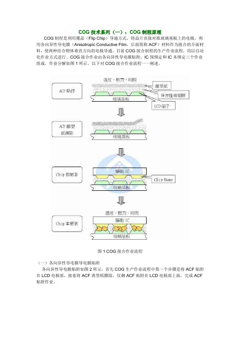
COG技术系列(一):COG制程原理COG制程是利用覆晶(Flip Chip)导通方式,将晶片直接对准玻璃基板上的电极,利用各向异性导电膜(Anisotropic Conductive Film,后面简称ACF)材料作为接合的介面材料,使两种结合物体垂直方向的电极导通。
目前COG接合制程的生产作业流程,均以自动化作业方式进行。
COG接合作业由各向异性导电膜贴附,IC预绑定和IC本绑定三个作业组成,作业分解如图1所示,以下对COG接合作业流程一一阐述。
图1 COG接合作业流程(一)各向异性导电膜导电膜贴附各向异性导电膜贴附如图2所示,首先COG生产作业流程中第一个步骤是将ACF贴附在LCD电极部,接着将ACF离型纸撕除,仅剩ACF贴附在LCD电极部上面,完成ACF 贴附作业。
图2 ACF贴附作业(二)IC预绑定IC预绑定如图3所示,将完成ACF贴附作业的LCD搬送到IC预绑定工程进行IC预绑定作业,此工程需将IC对位到LCD相对的电极上,因此需进行CCD影像读取识别,透过电脑影像处理系统,分别识别IC和LCD上预设识别位置,由电脑自动运算相对坐标后可以准确将IC贴在LCD电极上,完成IC预绑定作业。
图3 IC预绑定作业(三)IC本绑定作业IC本绑定作业如图4所示,最后将完成IC预绑定作业LCD搬运到IC本绑定工程进行IC本绑定作业,此工程是COG制程品质的关键,压着温度、压着压力、压着时间是ACF 固化三要素,以下对其个别说明:1、压着温度:ACF接合胶材料主要是高分子树脂,主要可分为热固性(Thermal-Setting)与热塑性(Thermal Plastic)树脂两种,一般ACF制造商会提供ACF特性的技术资料,对于黏附性影响最大,太低的温度会导致树脂无法溶解,太高的温度便会使导电粒子流失,因此压着温度必须控制在最佳范围以确保制品的可靠性。
2、压着压力:对于导通电阻影响最大,太小的压力会导致导电粒子与电极之间的接触面积不够,而发生导电不良的情形,而太大的压力会压破导电粒子降低导通电阻,因此压着压力必须控制在最佳范围以维持良好的导电性。
COG工序流程介绍

COG工序流程介绍COG(Chip on Glass)是一种封装技术,将IC芯片直接封装在显示屏的玻璃基板上。
该工序流程主要包括准备工作、IC粘贴、焊线、探针测试和封装测试等过程。
首先是准备工作阶段。
首先,要准备好所有的器材和材料,例如IC芯片、探针、焊线、胶水等。
同时,还要准备好相关的工作设备,例如工作平台、显微镜、喷射流水线等。
在准备阶段,还需要进行IC芯片和玻璃基板的清洁工作,以确保粘贴和焊接的质量。
接下来是IC粘贴过程。
首先,需要将探针预先粘贴在IC芯片上,以后续的测试使用。
然后,将预先涂有胶水的IC芯片粘贴在玻璃基板上。
这个过程需要非常精确,要确保IC芯片与玻璃基板之间没有空隙,并且位置准确。
第三个是焊线过程。
焊线是将IC芯片与玻璃基板连接起来的重要步骤。
焊线可以使用红外焊接或者激光焊接等多种技术。
在焊线过程中,需要非常小心,确保焊线的质量和稳定性。
焊接完成后,还需要进行焊线清理工作。
继而是探针测试。
在COG封装工艺中,探针测试是一个非常重要的环节。
通过探针测试,可以对IC芯片进行功能和性能的测试。
这个过程需要使用特殊的测试设备,例如探针卡、测试平台等。
通过不同的测试方法,可以对IC芯片进行全面的测试,确保其质量和稳定性。
最后是封装测试阶段。
在这个阶段,封装好的IC芯片将进行性能和可靠性测试。
这个测试过程通常包括一系列的严格测试,例如温度循环、高温高湿、振动等。
通过这些测试,可以验证IC芯片的质量和稳定性,并对其进行可靠性评估。
总的来说,COG工序流程是一个多环节、精细化的工作过程。
每个环节都需要高度的技术要求和精确度,以确保COG封装的质量和稳定性。
只有在每个环节都严格执行,并进行有效的质量控制,才能保证COG封装的可靠性和性能。
cog工作原理
COG工作原理详解引言COG(Cognitive Operation Group)是一种基于认知计算的人工智能系统,其工作原理涉及到多个方面,包括认知计算、神经网络、机器学习等。
本文将深入探讨COG的工作原理,以便更好地理解COG的工作机制和应用。
认知计算认知计算是指模拟人类智能过程的计算方法。
COG采用认知计算作为其基础,以模拟人类的感知、认知和决策过程。
认知计算主要包括以下几个方面的内容:感知感知是指通过感官获取外界信息的过程。
COG通过传感器模块获取环境中的视觉、听觉、触觉等感知信息。
例如,COG可以通过摄像头获取图像信息,通过麦克风获取声音信息。
理解理解是指对感知到的信息进行解析和理解的过程。
COG通过使用自然语言处理和计算语言学的技术,将感知到的信息转化为计算机可以理解的形式。
例如,COG可以通过语音识别将语音信息转化为文本信息。
推理推理是指基于已有的知识和信息,通过逻辑推理和推断,得出新的结论和判断的过程。
COG利用知识库和推理引擎进行推理,从而可以根据已有的知识和信息做出决策和判断。
例如,COG可以根据已有的知识和信息,推断出某个事件的可能性。
学习学习是指通过获取新的知识和经验,不断改善和完善自身的过程。
COG利用机器学习的方法,从大量的数据中学习和发现规律,从而提高自身的性能和能力。
例如,COG可以通过观察和分析大量的图像数据,学习识别不同物体的能力。
COG的工作原理COG的工作原理可以分为以下几个步骤:1. 数据收集与预处理COG首先通过传感器模块收集环境中的感知信息,例如图像、声音等。
然后对这些感知信息进行预处理,将其转化为计算机可以处理的形式。
例如,对图像进行降噪处理、对声音进行语音识别等。
2. 特征提取与表示在预处理之后,COG需要对感知信息进行特征提取和表示。
特征提取是指从原始数据中提取出具有代表性的特征。
例如,对于图像数据,可以采用卷积神经网络(CNN)提取图像的特征。
COG制程原理及流程
1.阵列制程2.组立制程3.模组制程最后就是我们看到的产品了.1.阵列制程1)一片表面光滑,没有任何杂质的玻璃,是制造 TFT 玻璃基板最主要的原料.在制作之前,需用特殊的冼净液,将玻璃洗得干干净净,然后脱水,甩干.2)要使玻璃基板镀上金属薄膜,需先将金属材料放在真空室内,让金属上面的特殊气体产生电浆后,金属上的原子就会被撞向玻璃,然后就形成一层层的金属薄膜了.3)镀完金属膜后,我们还要镀上一层不导电层与半导电层,在真空室内,先将玻璃板加温,然后由高压电的喷洒器喷洒特殊气体,让电子与气体产生电浆,经过化学反应后,玻璃上就形成了不导电层与半导体层。
4)薄膜形成后,我们要在玻璃上制作电晶体的图案。
首先,要进入黄光室喷上感光极强的光阻液,然后套上光罩照射蓝紫光进行曝光,最后送到显影区喷洒显影液, 这样可以去除照光后的光阻,还可以让光阻层定型哦。
5)光阻定型后,我们可用蚀刻进行湿式蚀刻,将没有用的薄膜露出,也可用电浆的化学反应进行干式蚀刻,蚀刻后再将留下的光阻以溜液去除,最后就产生电晶体所需要的电路图案了。
6)要形成可用的薄膜电晶体,需要重复清洗,镀膜,上光阻,曝光,显影,蚀刻,去光阻等过程,一般来说,要制造 TFT-LCD,就要重复 5 到 7 次。
2.组立制程1)完成薄膜电晶体玻璃基板后,我们就要进行液晶面板的组合了,液晶面板是由电晶体玻璃基板与彩色滤光片组合而成,首先,我们要先将玻璃洗干净,再进行下一个步骤。
TFT-LCD 的整个制造过程都必须在无尘室内,这样才不会有杂质在显示器里面。
2)彩色滤光片是以化学涂布的方式,在玻璃上形成红、绿、蓝的颜色,整齐排列后再覆盖一层会导电的薄膜即完成。
3)在整个组合的过程中,首先我们要为布满电晶体的玻璃和彩色滤光片涂上一层化学薄膜,然后再进行配向的动作。
4)在组合二片玻璃板之前,我们要先平均布满类似球状的隙子固定间隔,以免液晶面板组合后,二片玻璃向内凹曲。
通常液晶面板在组合时,会留下一个或二个缺口,以利后续灌入液晶,接着就以框胶及导电胶封在二片玻璃边缘,如此就完成玻璃的组合了。
点阵液晶屏COG的工艺详解

点阵液晶屏COG的工艺详解点阵液晶屏COG制造工艺至今已有近十年的发展历史,它的发展与IC的小型化、超薄化以及LCD显示屏光刻精度的精细化是密不可分的,我司生产COG液晶屏也有近6年的时间了,积累了大量宝贵的经验。
COG液晶:1、COG工艺流程如下所示。
LCD显示屏->将ACF邦贴到屏上->将裸芯片从芯片拖盘中取出->检查裸芯片的对位标记->检查LCD屏上对位标记->芯片与LCD屏对位->热压头将芯片与LCD屏邦贴到一起->整个邦贴过程完成2、工艺要点(1)邦定IC时要求IC对位标志与LCD屏上的对位标志吻合;(2)需用无尘布沾溶剂清除液晶屏上压着区的异物,使用UV灯清除液晶屏上压着区的有机物;(3)ACF贴附精度为+100μM;(4)要注意ACF的储存条件和控制好ACF邦定的时间、热压温度和压头的压力。
ACF反应率要求达到80%以上。
例如使用日立(HITACHI)公司的AC-8304Y的ACF,其保存条件为:在室温约25℃和湿度70%RH情况下,有效期1个月;在温度-10℃~5℃时有效期为6个月。
ACF使用工艺条件:贴ACF温度100±10℃(ACF的实际温度),压强约1Mpa,时间1~5秒,主压压强约50~150Mpa(指每个IC BUMP上的压强,根据ACF中导电球的受压效果决定压力的大小)。
ACF 温度220±20℃(ACF的实际温度),时间7~10秒。
所有ACF从冰箱中取出后需在室温条件下放置1小时后方可打开包装;(5)必须确保前工序光刻工艺的成品率,严格控制断笔和连笔(主要在IC接口处);(6)LCD屏需经严格测试,防止废品漏测,造成材料浪费及品质不良;(7)显微镜下全检防止断笔流出,要求IC电极上的导电粒子压痕至少5个,相邻BUMP之间不能互相接触;(8)COG成品必须100%检测;(9)COG-LCD产品一般多为高密度产品,制造时要求光刻段的分辨率较高,PI定向膜与摩擦均匀性较好,在线间隙小于15μM时要求增加TOP(涂覆绝缘层)工艺,以避免短断路、显示不均、串扰和功耗电流大等现象的出现;(10)COG常见不良品包括:IC异物、IC压痕不良、ACF 贴附不良、IC对位偏移、IC厚度不均、IC电遇不良、IC破裂/刮伤、IC BUMP不良等。
COG工艺流程培训
COG工艺流程培训1. 介绍COG(Chip-on-Glass)工艺是一种将IC芯片直接封装在玻璃基板上的先进封装技术,广泛应用于液晶显示器(LCD)驱动芯片的制造过程中。
COG工艺流程培训旨在向制造商、技术人员和工程师介绍COG工艺的基本原理、关键步骤和操作流程。
2. COG工艺步骤COG工艺通常包括以下关键步骤:2.1 探针测试和IC切割在COG工艺的第一步中,需要将待封装的IC芯片进行探针测试,以确保其性能符合要求。
之后,使用特殊的切割工艺将芯片切割为适当的尺寸和形状。
2.2 COB粘接在COB(Chip-on-Board)粘接阶段,将已切割的IC芯片使用导电粘合剂粘贴到玻璃基板上。
此粘接步骤需要确保IC芯片与基板之间的电连接和机械连接。
2.3 电极连接在电极连接阶段,通过使用先进的微电焊技术,将IC芯片的电极与玻璃基板上的薄膜电极进行连接。
这种连接方式可以实现可靠的电信号传输。
2.4 基板清洗基板清洗是确保COG封装质量的重要步骤。
通过使用适当的溶剂和清洗工艺,去除粘合剂残留物和其他污染物,以保证封装的可靠性和稳定性。
2.5 封装测试在封装测试阶段,对COG封装进行全面的功能和可靠性测试。
这些测试包括电性能测试、温度循环测试和振动测试等。
封装测试的目的是验证COG工艺的产品质量和性能。
3. COG工艺优势COG工艺具有许多优势,使其在液晶显示器制造行业中得到广泛应用:•封装体积小:COG工艺可以实现IC芯片直接封装在纤薄的玻璃基板上,使整个封装体积更小,有利于显示器模组的薄型化设计。
•电气性能优异:通过COG工艺实现IC芯片与触摸面板的紧密连接,可以减少电阻、电容等电性能损失,提高显示器的响应速度和触摸精度。
•可靠性高:COG工艺中使用的导电粘合剂和微电焊技术能够提供可靠的电连接和机械连接,使封装的产品具有较好的工作稳定性和可靠性。
•生产效率高:COG工艺流程相对简单,生产效率高,适用于大规模生产。
COG工艺流程范文
COG工艺流程范文COG工艺流程是一种在封装显示器元件时使用的一种工艺流程。
COG,也被称为Chip on Glass,是一种将驱动芯片直接封装到玻璃基板上的技术。
下面是一种常见的COG工艺流程,包括了准备和制备玻璃基板、制作电路层、制作封装层、测试和检验以及结束阶段。
1.准备和制备玻璃基板:首先,原始的玻璃基板要经过清洁和切割,以确保表面干净并获得所需大小。
2.制作电路层:在玻璃基板上制作电路层,这包括电路连接线的制作。
这一步骤通常使用光刻技术,通过覆盖感光胶在玻璃基板上,然后通过模板上的图案进行曝光,最后通过化学处理将感光胶进行固定。
固定后,可使用蚀刻液将不需要的部分蚀刻掉,并进行清洗和干燥。
3.制作封装层:在电路层之上制作封装层。
这一步骤通常使用类似于电路层的光刻技术。
在这一步骤中,还可能需要在电路层上应用一层粘合剂,以确保封装层的粘附。
然后,通过混合粘合剂和封装树脂的方式将其涂在封装层上。
最后,将封装层进行固化,通常使用热压。
4.测试和检验:封装完成后,需要对芯片进行测试和检验,以确保其功能正常并且没有制造缺陷。
这包括使用测试设备对芯片进行电气和光学测试。
测试后,可能需要对芯片进行修复或标记。
5.结束阶段:在测试和检验后,COG封装的显示器元件就完成了。
最后,将这些元件与其他部件组装在一起构成完整的显示器。
总之,COG工艺流程是一种将驱动芯片直接封装到玻璃基板上的技术。
这种工艺流程涉及到准备和制备玻璃基板、制作电路层、制作封装层、测试和检验以及最后的组装阶段。
这种工艺流程可以提供显示器元件的高集成度和稳定性,并且可以减少显示器的体积和重量。
- 1、下载文档前请自行甄别文档内容的完整性,平台不提供额外的编辑、内容补充、找答案等附加服务。
- 2、"仅部分预览"的文档,不可在线预览部分如存在完整性等问题,可反馈申请退款(可完整预览的文档不适用该条件!)。
- 3、如文档侵犯您的权益,请联系客服反馈,我们会尽快为您处理(人工客服工作时间:9:00-18:30)。
AACCFF AAttttaacchh
IC Prebond
IICC mmaaiinnbboonndd
CCeellll uunnllooaaddeerr
VViissuuaall IInnssppeeccttiioonn
9水0目工制目工制滴0目工制m的具程的具程角::参J温的具程目::参</将数L度c3o的清数U目::参•m:ca0加工目eVd目:度无工工l除:的2le清无数热传具的•ru的将<将具/具C:AT送n:除尘:照:r:CIea:iIC:至:tCFyl检A射制制U压将布尚C8l/,机将上C预ICA0使工制Cn制查着ea台-累程程A±C8未/ls将压压A目l溶o6具程内P于s程CIl积参参C05CFe上a的C着r量着1FAtF:参剂e参ad压t照数数eeC预进:bt区压e于化lt显数F数着(lor行度a::贴传/丙/有ACn着cT微::硬是<e于hdCr送机酮la1A化镜无l区uu无否8F上CyC6至0nn物反/)-/0C合e±异8Cit机t0i应6leol2m乎5l物3台nl上J标v外/ec准ym2
PCB
PCB test SLC
JBO
COG Process
COG: Chip On Glass
Purpose: Bonding Driver with Cell
Key Components:
• Cell • ACF • Driver IC (LSI)
Cell
Cell Pad
Bonding area
ACF Introduction
COG Process ACF 反应率需达 80 % 以上
ACF Introduction
为何使用 AC-8623 (低温)
解决 Tool Mura 问题
COG Process Flowchart
CCeellll llooaaddeerr Wweettcleleaann
AC-8623
Conductive
8 ± 1 um
1.5 ± 0.1 mm 50 m
ห้องสมุดไป่ตู้
3 ± 1 um
44,000 ± 12,500 pcs/mm2
5.0 Ω or less
10E8 Ω or more
80℃/ 1MPa / 3s 190℃/ 100MPa / 10s
7 month / 30 days
10E9 Ω or more
80℃/ 1MPa / 3s 150℃/ 100MPa / 10s
4.5 month / 10 days
ACF Introduction
Conductive Particle
Bump (after bonding)
Bump (before bonding)
Bump (ACF cleaned)
目的: 垂直方向电气通电 水平方向电气绝缘
主要组成: 黏着剂 导电粒子
ACF Introduction
Force
Step 1 AC
IC
Introduction
ACF
F
Cell
Step 2
Each channel Conductive independently
IC ACF Cell
ACF Introduction
工具A:C-I8C60P1rebond uAnCit-8623
温压度力
18M0 制P±a程5 参数 180M±Pa5
时压间力
1AM3CP-s8a601
1AMC3-P8sa623
时温间度 压力
190 ± 5 312s5 MPa
150 ± 5 1235 MsPa
厂商建议100 MPa 厂商建议100 MPa
三、授课时数: 3-1:COG制程原理及动作流程15 min 3-2:COG制程检验规范 10 min 3-3:COG制程之Defect Mode 5 min
TFT LCD Process
Array
Cell
Module
JI
Assemble
Test
Cell Kitting
Laser Cut
COG
S/G
时间
10 s
10 s
COG Process Criteria
外观 ACF贴附 IC压痕 IC压著精度
COG Criteria(外观)
•TFT/CF 玻璃破损 比照Cell Kitting规格 线路刮伤 比照Cell Kitting规格
•偏光板 显示区內不可有压、刺伤
•IC IC背部不可有裂痕
COG 制程原理及流程
COG课程导览
一、课程目标: 1-1:使学员了解COG制程原理 1-2:使学员了解COG制程动作流程 1-3:使学员了解COG制程之检验规范 1-4:使学员了解COG制程之Defect Mode
二、课程对象: 2-1:LCM厂制程与设备工程师 2-2:对COG制程有兴趣的同仁
Expiration time(5 ℃/RT)
23 ± 3 um
50 um 15 ± 2 um
8 ± 1 um
1.5 ± 0.1 mm 100 m
3 ± 1 um 44,000 ± 12,500 pcs/mm2
5.0 Ω or less
AC-8601
23 ± 3 um
50 um 15 ± 2 um
Adhesive
COG Criteria (ACF贴附)
Case 1
MARK1
MARK2
ACF Case 2
ACF
ACF上缘上限/ACF upper limit ACF上缘下限/ACF lower limit
Hitachi ACF
Separator
Type Thickness Separator thickness Adhesive thickness Conductive thickness Width Length Particle size Conductive Particles Connection resistance Insulation resistance Attach parameter Mainbond parameter
Driver IC
Input side(FPC/PCB)
MEC IC Output side (Cell)
IC on Tray
Gold bump
Driver IC
Gold bump profile
Au
Ti / W Passivation
Al
ACF Introduction
ACF: Anisotropic Conductive Film (异方向性导电膜)
