框架断路器-ST40450-3MH使用手册_x.
人民电器 RDB5-40系列小型断路器 使用说明书

SERIESR DB5-40系列小型断路器符合标准:G B/T10963.1产品安装使用前,请仔细阅读使用说明书,并妥善保管,以备查阅。
警告1 严禁湿手操作断路器,否则可能发生电击事故。
2 断路器的短路保护特性工厂已经测试,若是在安装或使用过程中必须验证,则应使用经国家有关部门检测合格的专用测试台测试,严禁用负载线直接短路的试验方法,避免人身伤害。
注意1 断路器安装场所应无爆炸危险、无腐蚀性气体,并应注意防潮、防尘、防火、防震动。
2 断路器的过载保护特性已由制造厂整定,在使用过程中不可随意调整,以免影响性能。
3 为了您的安全,请合理选择断路器的短路保护特性要求,并合理配备安装导线。
4 本产品接触板为铜或铜合金,用户接铝导线时请采用铜铝过渡,搪锡或者加装铜接线鼻,以免导致铜、铝直接接触造成电化学腐蚀导致接线松动,接触电阻增大而烧损线路如因接线不合理出现线路烧毁,本公司概不负责,特此警告!5 接线时一定要接紧,且在安装使用一段时间后要再进行紧固,每次的拧紧力矩为(2~2.5)N·m。
6 安装按照产品说明书要求,包括安装方式、进线方式、适用条件、铜导线(铜排)截面积(参考值见附表A)。
-1-1 用途与适用范围RDB5-40小型断路器(以下简称断路器),主要用于交流50Hz(或60Hz),额定工作电压至230V,额定电流至40A,额定短路分断能力不超过4500A的保护配电线路中,作为线路不频繁接通、分断和转换之用,具有过载、短路保护功能。
产品符合:GB/T10963.1标准。
2 正常工作和安装条件2.1 周围空气温度上限不超过+40℃,下限不低于-5℃,且24h平均温度不超过+35℃。
2.2 安装地点海拔高度应不超过2000m。
2.3 大气相对湿度在周围空气温度为+40℃时不超过50%,在较低温度下允许有较高的相对湿度;例如20℃时达90%。
对由于温度变化偶尔产生在产品上的凝露应采取特殊的措施。
SST-ST45SF 450W 切换电源文档说明书

(10% TO 95% OF FINAL OUTPUT VALUE, @FULL LOAD)
115V-rms or 230V-rms
+ 3.3Vdc : 20ms Maximum + 5Vdc : 20ms Maximum + 12Vdc : 20ms Maximum + 5Vsb : 20ms Maximum - 12Vdc : 20ms Maximum
The specification below is intended to describe as detailedly as possible the functions and performance of the subject power supply. Any comment or additional requirements to this specification from our customers will be highly appreciated and treated as a new target for us to approach.
4.5. OVER VOLTAGE PROTECTION
Voltage Source +3.3V +5V +12V
Protection Point 3.76V-4.8V 5.6V-7.0V 13.0V-16.5V
4.6. OVER-CURRENT PROTECTION
OUTPUT VOLTAGE +3.3V +5V +12V1
Max. over current limit 60A 48A 45A
04
4.7. SHORT CIRCUIT PROTECTION
ST45系列智能控制器使用说明书

ST45-M系列智能控制器说明书一、用途:ST45-M系列智能控制器是智能框架式断路器配用的核心控制元件,该控制器可以显示设备或电网的工作电流、工作电压(带电压显示型),并根据负载电流的大小分别实现各种保护,使线路和电源设备免受过载、短路、接地等故障的危害。
按约定的保护方式断开控制回路,精度高、可靠性好,还有负载监控、故障报警、故障查询、在线试验、现场编程、密码设定等辅助功能。
二、符合标准本产品符合GB/T 14048.1-2000《低压开关设备和控制设备总则》和GB14048.2-2001《低压开关设备和控制设备低压断路器》,同时符合IEC60947-2《低压开关设备和控制设备第二部分低压断路器》的要求三、主要功能■过电流保护功能△过载长延时保护功能△短路反时限保护功能△短路定时限保护功能△短路瞬时保护功能△接地电流保护:三极产品接地电流保护可关断,四极产品接地电流保护与零序电流保护可选择其一。
△零序电流保护四极产品具有零序电流保护功能,该功能可以选择关断。
△各种保护的优先级如下:短路瞬时保护→定时限保护→长延时保护→接地保护→零序保护■负载监控功能:有方式一和方式二两种监控方式:使用方式一时,当负载电流大于监控设定电流时,一对触点闭合,用户可使用这对触点切除不重要负荷;如电流继续维持在大于监控电流状态,则又一对触点闭合,用户使用该触点再切除一部分负荷,达到监控电流的目的。
使用方式二时,当负载电流大于监控设定电流时,一对触点闭合,用户使用这对触点切除不重要负荷;如电流继续维持在大于监控电流状态,则又一对触点闭合,用户使用该触点再切除一部分负荷,此后如经过一段时间延时后,负载电流降到监控电流以下,则另外一对触点将使已切除的负载重新投入工作,达到电流监控的目的。
■欠压保护功能:如选择带电压显示型控制器,用户可以选择是否使用欠压保护功能,当选择该功能时,可通过控制器本身实现对电路三相端电压的欠压控制。
海洛斯操作手册(说明书)

HIROSS恒温恒湿机房精密空调操作手册HIMOD系列北京****科技有限公司技术部2009年01月01日目录第一章HIMOD系列海洛斯空调概述 (2)型号多 (3)控制技术先进 (3)制冷系统 (3)送风系统 (3)加湿系统 (3)加热系统 (4)1.7其它 (4)第二章HIMOD系列海洛斯空调型号含义 (4)第三章有关空调的一些资料 (5)气流组织方式(详见下图) (5)盖板纽开启方式(详见下图) (5)空调重量(单位:Kg) (5)机组尺寸及维护空间 (6)第四章制冷循环管路示意图 (7)风冷却(A型) (7)水冷却(W型) (8)双冷源(D型) (9)单系统(C型) (10)双系统(C型) (10)第五章调速风机调速接线示意图 (11)第六章MICROF ACE概述 (12)概述 (12)面板简介液晶显示屏 (13)液晶显示屏介绍 (13)第七章MICROF ACE面板的操作 (13)第八章控制器的使用 (14)控制器(HIROMATIC)概述 (14)控制器的操作 (15)菜单结构 (17)第九章日常维护及特殊维护 (18)日常维护 (18)特殊维护 (19)第十章常见报警及处理 (20)低压报警 (20)高压报警 (21)加湿报警 (21)失风报警 (21)电加热过热报警 (22)显示器发黑 (22)空调不制冷 (22)附录1:参数列表 (22)附录2:报警内容列表 (26)附录3:各菜单项含义: (28)第一章HIMOD系列海洛斯空调概述HIMOD系列海洛斯空调(HIMOD空调)是当今世界上最先进的机房专用恒温恒湿机房专用精密空调。
随着IT业的突飞猛进的发展,各种布局、面积差别很大的机房如雨后春笋般纷纷出现了,使用环境也不一而同。
为适应各种不同要求的机房,新开发的海洛斯HIMOD系列空调应运而生。
她是在保留她的前一代产品HIRANGE系列机房空调的优点,又应用了当今世界上提高了的制冷技术及制冷部件制造工艺,使用当今最先进的模块化设计理念生产出来的高科技机房空调产品。
亚拓安装调试图解

亚拓450从零安装调试详细讲解T-REX 450 SE-组装方式/调整/设定参考第1步:首先将机身固定柱和主轴固定座及电池固定座左侧两颗螺丝拆下,方便服务器安装第2步:将第一颗服务器由内往外安装第3步:同样的由内往外安装第二颗服务器,并将讯号线排列整齐用速线带固定,切记(1.速线带头在机身内侧2.在固定于册版的地方用透明胶带包覆两圈,防止组装时讯号线破损)第4步:将伺服机讯号线由内侧版经沟槽穿往机身外侧第5步,将服务器的讯号线整理后,再用蛇管包覆第6步:将机身固定柱和主轴固定座及电池固定座左侧两颗螺丝装回原来位置记得要上螺丝胶喔第7步:将中间的侧版固定柱套入,并对准螺丝孔.将马达固定座装上下侧版第8步:1.利用马达固定座将上.下侧版组合2.将中侧版固定柱锁上螺丝第9步:将服务器讯号线穿过上.下侧版并将左侧三颗螺丝锁上第10步:右侧版先锁上1的螺丝,其它两颗先不锁第11步:将所需的马达同齿固定后,在将马达固定在马达坐上第12步:将马达线穿过机身底板和组装好的脚架,并将脚架固定第13步:将皮带穿过尾管(注意皮带的方向性)并将尾服务器座套入尾管,然后跟机身组合,并将垂直/水平/支撑架装上,调整皮带的松紧度后上紧尾管固定座的螺丝第14步:金属尾传动轮座组固定前,需确认与尾管固定座呈平行状态第15步:陀螺仪的整线后用蛇管包覆第16步:将陀螺仪用双面胶固定在尾管固定座上后,将包覆好的讯号线穿过上.下侧版后再将右侧版的两颗螺丝上紧(陀螺仪安装在尾固定座的下方,以防炸机时被副翼打到)第17步:先抓出尾服务器的中点,并将球头固定在服务器的摆臂上(上下两个圈是行程终点),并将服务器固定在尾伺服座上第18步:装好尾服务器时,套上连杆后,注意,这是重点1,尾舵控制组需在尾主轴中央2.调整尾服务器座让连杆跟尾管平行3.尾服务器摆臂球头需在中点4. 尾连杆和尾管尽量跟尾管呈平行以上确定后在固定尾伺服座螺丝第19步:1.将主轴上的连杆按说明书上的长度组装,并套上摆臂平衡杆先量好两边相等长度后套入平衡杆重垂在装上平衡翼2.将主轴和机身组合第20步:组合好后请注意大齿盘于机身的间隙,不能摩擦到机身或尾传动轮第21步:调整马达铜齿的高度并将铜齿固定螺丝上紧,调整马达与大齿盘的间隙后再将马达固定螺丝上紧第22步:1.用2mm钻尾将欲锁球头的摆臂扩孔2.将球头利用螺母固定在摆臂上3.将多余的摆臂去掉.以免摆动时干涉4.将服务器连杆依说明书长度组装好第23步:将组装好的摆臂套上服务器,先不上服务器螺丝,以便调整时需拆下,此时连杆都是呈垂直状态第24步:接收的整理1.用热缩套管或由机的油管将接收线的前端包覆,以防接收线和侧版接触而出现干扰现象,相信很多人有这个经验2.用1mm的泡棉将接受包覆并用透明胶带在包覆,以防日久泡棉脱落,这可以防止摔机后的碰撞以以多一层的防干扰的作用第25步:1.用双面胶将接收固定在底板2.将讯号线接上接收第26步:1.用打火机熏烤将热缩套管定型你要的角度2.在用热缩套管将整理的接收线固定在线管上第27步:将电子变速器的讯号线穿过脚架和底板之间并接上接收(马达线先不要接,以便遥控器设定和调机)------------------以上是机械及电子部件的安装---------------第28步:控的设置,打开遥控器进入SW ASH TYP,打开选项选择120度第29步:接上电池,将摆臂尽量以90度脚平行装上,并推油门游戏杆以确认伺服机的方向正确,如有反向,可进入REV.SW个别调整正确方向第30步:如摆臂有微些差距,可进入sub trim个别微调至所有摆臂至平行,调整好后记得看看十字盘是否平行,如没平行,调整十字盘连杆使起平行既可第31步:接下来先将主旋翼做好静态平衡后,装上直升机,并将服务器螺丝锁上第32步:进入遥控器选项里的PIT.CURV.1.并将油门游戏杆推至中点2.在NORM设定页面3.将EXP显至ON的位置,这可以自行调整曲线较为顺畅第33步:已有贴配重贴纸的桨为主1.将螺距规套上,并以螺距规的上沿跟平衡杆呈平行2.此时应为0度,如没0度,可依差距大小调整连杆使其成为0度第34步:将油门游戏杆推至最高并记下为+11度第35步:将油门推至最低,并记下为-11度,对高手来说,这个螺距应该是可以的第36步:如想减少螺距行程,可进入swash mix的PIT降低%数(5%为一度左右),所以我降了10%,此时螺距为(-9 0 +9)这应该适合一般飞友第37步:接下来是在进入PIT. CURV设定NORM的螺距,第一点位置设定为-2度,此时数据为38%第38步:接着将油门游戏杆推至中点3的位置(约是停悬点),为+5度,此时该点数据为75%第39步:在来是将刚刚设定的38%和75%以及最高的100%三点中的曲线,设定调整一条顺畅的拋物线,这样一来,在操控的过程会顺畅许多,不会又高高低低的情况发生第40步:接下来进入THRO CHRV的NORM页面设定油门曲线,首先在第3点(中点)位置将数据设定为68%第41步:接下来是一般人常遇到也是最让你头痛的尾巴设定,如果你刚刚再组装的时候有按照图示安装,基本上尾服务器的中立点已经抓好了,所以不会有偏的问题发生,只要了解陀螺一的功能和调整就可以了,A.接上电源如果灯恒亮,就表示锁头模式,1数字/模拟的切换开关,如果你用的尾舵机不是数码的,必须将开关切至OFF的位置,如果是数码舵机择切换至ON的位置2.陀螺仪反向开关3.延迟开关,如果是数字服务器这个开关可以不用管他,在O的位置.如是用模拟服务器,感度以将很低仍有追踪现象,可调整此开关改善4.陀螺仪行程开关,如行程太大会产生操控尾舵时,定点会有抖几下的情况,可降低此行程来改善第42步:确认方向舵方向,通常尾舵控制组跟方向游戏杆是反方向移动,这才是正确的第43步:确认好后接下来进入遥控器GYRO SENS AUTO页面设定陀螺仪感度POS.0为一般飞行感度设定POS.1为3D飞行感度设定设定好感度后不要忘了也要进入由上角将POS.0和POS.1个别设定好,如此一来,感度才会跟着你切换的飞行模式而改变资料来源:亚拓台湾官网论坛第44步:设定好后,将电子变速器和马达的线依颜色接上,并将固定第45步:设定的过程中,有些飞友会利用这个页面调整服务器的行程,来达到所需的螺距,这是错误的,就算调整好了,+-数据不相等,这会产生打动作时,左右的速度不均现象第46步:还有一种错误的调整螺距的方式,如图示,降低/提高螺距曲线的%数来迎合所需的螺距,这也会让你在操控时,游戏杆上下不均匀,也缩短了螺距变化的空间,所谓一步错步步错!第47步:接下来是调整双桨,以量螺距的桨为机准桨(贴配重贴纸的桨),此桨不动视另一只桨高低作调整就可以了,完工!。
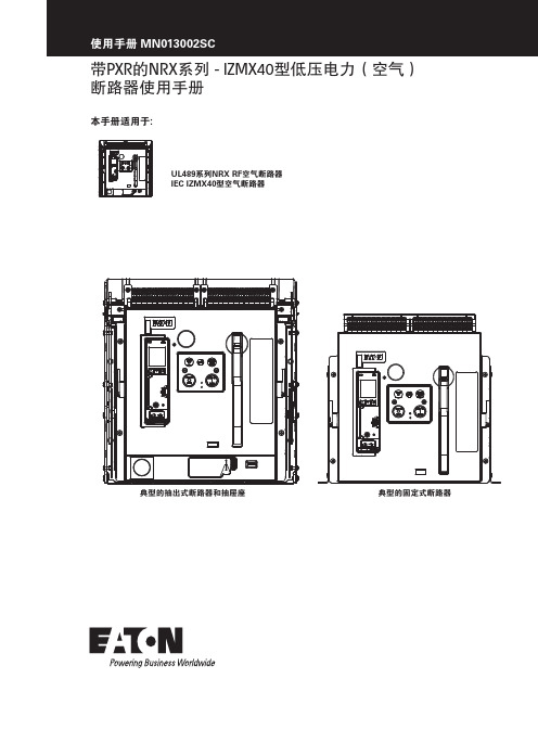
NRX系列-IZMX40型低压电力(空气)断路器使用手册说明书

带PXR的NRX系列 - IZMX40型低压电力(空气)断路器使用手册系列NRX RF空气断路器型空气断路器使用手册 MN013002SC目录第一部分:简介 (1)目的 (1)安全须知 (1)具备资格的人员 (1)概述 (1)产品标签及标识 (2)断路器概述 (3)抽出式断路器和抽屉座 (3)固定式断路器 (3)第二部分:收货、拆箱和检查 (8)建议使用的工具 (8)断路器的拆箱和检查 (8)断路器的检查 (10)断路器的存放 (10)第三部分:断路器的一般操作及描述 (11)概述 (11)抽出式断路器在抽屉座内的安装 (11)失配联锁保护 (12)抽出式断路器的位置 (12)安装固定式断路器 (14)断路器基本组件 (14)操作机构 (15)手动操作 (15)电动操作 (16)防跳特性 (16)第四部分:断路器特性和附件 (16)概述 (16)灭弧室 (16)电子脱扣系统 (16)基于微处理器的脱扣器 (16)额定值插头 (17)电流互感器 (17)壳架电流模块 (17)脱扣驱动器 (17)固定的高瞬时不可调脱扣 (17)ii带PXR的NRX系列-IZMX40型低压电力(空气)断路器 MN013002SC 2018年9月 使用手册 MN013002SC非自动装置 (17)二次端子和接线图 (18)一般接线说明 (18)附件装置 (19)附件盘 (19)左侧附件盘 (19)右侧附件盘 (19)分励脱扣器(ST) (20)欠压脱扣器(UVR) (20)过电流脱扣开关(OTS) (20)辅助开关 (20)其它内部电气附件 (20)弹簧脱扣器(SR) (20)准备合闸开关(LCS) (20)电动马达 (20)机械附件 (20)未联锁的弹出式机械脱扣指示器 (20)联锁的弹出式机械脱扣指示器 (21)操作计数器 (21)断开钥匙锁 (21)按钮盖 (21)安全停止按钮盖 (21)抽屉座安全挡板 (21)门框 (21)IP55 防尘及防水罩 (21)机械联锁 (21)NRX系列手册 (21)第五部分:抽出式断路器的安装尺寸图 (23)概述 (23)抽出式断路器 (23)第六部分:固定式断路器的安装尺寸图 (39)概述 (39)固定式断路器 (39)带PXR的NRX系列-IZMX40型低压电力(空气)断路器 MN013002SC 2018年9月 iii使用手册 MN013002SC第七部分:检查和维护 (53)概述 (53)一般性建议 (53)何时检查 (53)检查内容 (53)现场功能测试 (53)手动操作功能测试 (54)电气操作功能测试 (54)脱扣器的测试步骤 (54)灭弧栅的检查 (54)一次触头检查 (56)其他修改和/或更换 (56)脱扣器的更换 (56)电流互感器的更换 (56)壳架电流模块的更换 . . . . . . . . . . . . . . . . . . . . . . . . . . . . . . . . . . . . . . . . . . . . . . . . . .56第八部分:故障排除 (56)简介 (56)免责条款及责任限制 (58)iv带PXR的NRX系列-IZMX40型低压电力(空气)断路器 MN013002SC 2018年9月 v带PXR 的NRX 系列-IZMX40型低压电力(空气)断路器 MN013002SC 2018年9月 警告和小心是本手册操作步骤的一部分,用来保护人员安全和设备不受损坏。
400V配电开关简要操作手册

电厂400V配电开关简要操作手册我厂400V配电柜主要分为框架式和抽屉式两大类。
开关柜功能单元与母线或电缆之间,用接地的金属板或塑料制成的功能板隔开,形成母线、功能单元和电缆三个区域。
每个功能单元之间也有隔离措施。
一、框架断路器柜框架式开关采用3WT8型开关,,它不仅可以接通和分断正常负载电流和过载电流,而且可以接通和分断短路电流。
主要在不频繁操作的低压配电线路或开关柜中作为电源开关使用,并对线路、电器设备等实行保护,当它们发生严重过流、过载、短路、断相、漏电等故障时,能自动切断线路,起保护作用,应用十分广泛。
智能控制器是框架式断路器上的保护装置,也是断路器的核心控制装置。
集保护、报警、测量、维护、运行管理等功能一体,各类参数在线可调。
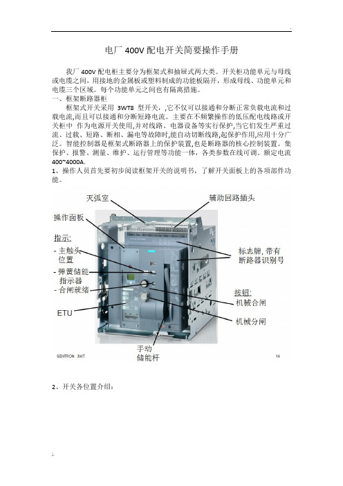
额定电流400~4000A.1、操作人员首先要初步阅读框架开关的说明书,了解开关面板上的各项部件功能。
2、开关各位置介绍:3、开关抽出后:4、智能控制器(ETU)面板介绍:开关出现报警信号需要记录报警信息,打开透明塑料面板复归信号5、合闸就绪条件:6、开关操作:以检修状态转热备用为例:检查电动机一次接线完整检查开关双重编号正确摘下开关处“禁止合闸有人工作”标示牌检查开关机械状态指示在“0”位检查开关零序保护继电器压板已投入(此压板只有部分设备配置)合上开关柜内直流电源Q11开关检查开关柜内直流电源Q11开关在“合闸”位合上开关柜内交流电压DK开关检查开关柜内交流电压DK开关在“合闸”位检查开关分闸指示灯“绿灯”亮(直流电源开关未合灯不会亮)按下开关本体手动分闸按钮(防止带负荷送开关,此按钮不按下摇把遮板打不开)打开开关摇把遮板摇入开关至红色“Betrieb Conn”工作位(如果操作任务是送实验位则是摇入开关至蓝色“Pruf Test”试验位。
请注意开关实验位与工作位没有锁定装置)检查开关在红色“Betrieb Conn”工作位关上开关摇把遮板(开关需在工作位、实验位或检修位,摇把遮板才能关上)检查开关合闸准备就绪指示“蓝灯”亮(蓝灯不亮开关不能合闸)检查开关本体弹簧机械储能指示为储能状态(注意:摇进开关时一定要缓慢进行,让插件柔和结合,防止速度过快损伤插件;摇出开关时同样要缓慢进行,让一次插件慢慢分离,防止速度过快损伤插件)以开关热备用转检修位为例:检查开关双重编号正确检查开关机械状态指示在“0”位检查开关分闸指示灯“绿灯”亮按下开关本体手动分闸按钮打开开关摇把遮板摇出开关至绿色“Trenn Disconn”检修位检查开关在绿色“Trenn Disconn”检修位关上开关摇把遮板断开开关柜内直流电源Q11开关检查开关柜内直流电源Q11开关在“分闸”位断开开关柜内交流电压DK开关检查开关柜内交流电压DK开关在“分闸”位在开关处挂上“禁止合闸有人工作”标示牌7、关于开关机构储能:正常是控制电源开关合闸后电气自动储能,如果电气不能储能,应手动操作储能杆下压后松开再下压后松开,往复数次直至显示弹簧已压缩的储能指示。
停电更换0.4kV框架式断路器作业指导书

停电更换0.4kV框架式断路器作业指导书
1.范围
本指导书适用于停电更换0.4kV框架式断路器作业。
2.规范性引用文件
下列文件中的条款通过本指导书的引用而构成本指导书的条款。
凡是注日期的引用文件,其随后所有的修改单(不包括勘误的内容)或修订版均不适用于本指导书,但鼓励根据本指导书达成协议的各方研究是否可使用这些文件的最新版本。
凡是不注日期的引用文件,其最新版本适用于本指导书。
GB50171-92 《电气装置安装工程盘、柜及二次回路结线施工及验收规范》
GB 50150-2006 《电气装置安装工程电气设备交接试验标准》
3.安全及预控措施
4.作业准备
5.作业周期
必要时进行。
6.作业内容及方法6.1 作业开工
6.2 作业步骤及工艺要求
6.3 异常现象及对策
6.4 竣工验收
7.作业记录
8.附件
8.1 工作人员分工明细表
8.2 主要工器具、机械清单
注:附件8.1、8.2使用时,应根据实际情况填写。
PT40-m智能控制里板

PT40-M智能控制器一、用途:ST45-M系列智能控制器是智能框架式断路器配用的核心控制元件,该控制器可以显示设备或电网的工作电流、工作电压(带电压显示型),并根据负载电流的大小分别实现各种保护,使线路和电源设备免受过载、短路、接地等故障的危害。
按约定的保护方式断开控制回路,精度高、可靠性好,还有负载监控、故障报警、故障查询、在线试验、现场编程、密码设定等辅助功能。
二、符合标准本产品符合GB/T 14048.1-2000《低压开关设备和控制设备总则》和GB14048.2-2001《低压开关设备和控制设备低压断路器》,同时符合IEC60947-2《低压开关设备和控制设备第二部分低压断路器》的要求三、主要功能■过电流保护功能△过载长延时保护功能△短路反时限保护功能△短路定时限保护功能△短路瞬时保护功能△接地电流保护:三极产品接地电流保护可关断,四极产品接地电流保护与零序电流保护可选择其一。
△零序电流保护四极产品具有零序电流保护功能,该功能可以选择关断。
△各种保护的优先级如下:短路瞬时保护→定时限保护→长延时保护→接地保护→零序保护■负载监控功能:有方式一和方式二两种监控方式:使用方式一时,当负载电流大于监控设定电流时,一对触点闭合,用户可使用这对触点切除不重要负荷;如电流继续维持在大于监控电流状态,则又一对触点闭合,用户使用该触点再切除一部分负荷,达到监控电流的目的。
使用方式二时,当负载电流大于监控设定电流时,一对触点闭合,用户使用这对触点切除不重要负荷;如电流继续维持在大于监控电流状态,则又一对触点闭合,用户使用该触点再切除一部分负荷,此后如经过一段时间延时后,负载电流降到监控电流以下,则另外一对触点将使已切除的负载重新投入工作,达到电流监控的目的。
■欠压保护功能:如选择带电压显示型控制器,用户可以选择是否使用欠压保护功能,当选择该功能时,可通过控制器本身实现对电路三相端电压的欠压控制。
欠压脱扣器的设定电压值和延时时间可以在设定页内由用户自行设定。
Series NRX 固定断路器三路电线路锁定套件安装与取用说明说明书

Figure 8. Step 8
ATTENTION
FIGURE 8 SHOWS THE TYPICAL CABLE ROUTING FOR TYPE 32 INTERLOCKS AND FIGURE 9 SHOWS THE TYPICAL ROUTING FOR TYPES 31 AND 33. THE CABLE MOUNTING ON THE DRIVE SIDE IS THE SAME FOR ALL TYPES. MOUNTING FOR THE DRIVEN SIDE OF TYPES 31 AND 33 IS SHOWN IN FIGURES 14-16. MOUNTING FOR THE DRIVEN SIDE OF TYPE 32 IS SHOWN IN FIGURES 17-20.
Three-Way Cable Interlock Kit
Instructions apply to:
Series NRX, Type NF Frame ANSI, UL1066, UL489 / IEC, IZMX16, IZM91
WARNING
(1) ONLY QUALIFIED ELECTRICAL PERSONNEL SHOULD BE PERMITTED TO WORK ON THE EQUIPMENT. (2) ALWAYS DE-ENERGIZE PRIMARY AND SECONDARY CIRCUITS IF A CIRCUIT BREAKER CANNOT BE REMOVED TO A SAFE WORK LOCATION. (3) DRAWOUT CIRCUIT BREAKERS SHOULD BE LEVERED (RACKED) OUT TO THE DISCONNECT POSITION. (4) ALL CIRCUIT BREAKERS SHOULD BE SWITCHED TO THE OFF POSITION AND MECHANISM SPRINGS DISCHARGED. FAILURE TO FOLLOW THESE STEPS FOR ALL PROCEDURES DESCRIBED IN THIS INSTRUCTION LEAFLET COULD RESULT IN DEATH, BODILY INJURY, OR PROPERTY DAMAGE.
框架断路器-ST40450-3MH使用手册_x

2.1 产品分类 .......................................................................................................................................... 5 2.1.1 选型说明 .................................................................................................................................. 5 2.1.2 基本功能 .................................................................................................................................. 6 2.1.3 通讯功能 .................................................................................................................................. 6 2.1.4 增选功能选择 ........................................................................................................................... 6 2.1.5 区域连锁及信号单元的选择 .................................................................................................. 7
MITSUBISHI ELECTRIC MGFC40V4450 说明书

< C band internally matched power GaAs FET >MGFC40V44504.4 –5.0 GHz BAND / 10WDESCRIPTIONThe MGFC40V4450 is an internally impedance-matched GaAs power FET especially designed for use in 4.4 – 5.0 GHz band amplifiers. The hermetically sealed metal-ceramic package guarantees high reliability.FEATURESClass A operationInternally matched to 50(ohm) system ∙ High output powerP1dB=10W (TYP .) @f=4.4 – 5.0GHz ∙ High power gain GLP=11dB (TYP .) @f=4.4 – 5.0GHz ∙ High power added efficiencyP .A.E.=32% (TYP .) @f=4.4 – 5.0GHz ∙ Low distortion [item -51] IM3=-45dBc (TYP .) @Po=29dBm S.C.LAPPLICATION∙ item 01 : 4.4 – 5.0 GHz band power amplifier∙ item 51 : 4.4 – 5.0 GHz band digital radio communicationQUALITY∙ IGRECOMMENDED BIAS CONDITIONS∙ VDS=10V ∙ ID=2.4A Refer to Bias Procedure ∙ RG=50ohmAbsolute maximum ratings (Ta=25︒C)Symbol Parameter Ratings UnitVGDO Gate to drain breakdown voltage -15 V VGSO Gate to source breakdown voltage -15 V ID Drain current 7.5 A IGR Reverse gate current -20 mA IGF Forward gate current 42 mA PT *1 Total power dissipation 42.8 W Tch Cannel temperature 175 ︒C TstgStorage temperature-65 to +175︒C*1 : Tc=25︒CElectrical characteristics (Ta=25︒C)Symbol ParameterTest conditionsLimitsUnitMin. Typ. Max.IDSS Saturated drain current VDS=3V,VGS=0V - 4.5 6 A gmTransconductanceVDS=3V,ID=2.2A - 2 - S VGS(off)Gate to source cut-off voltageVDS=3V,ID=40mA - -3 -4 V P1dB Output power at 1dB gain compression39.5 40.5 -dBm GLP Linear Power Gain 9 11 - dB ID Drain current - 2.4 - A P .A.E. Power added efficiency -32 - % IM3 *23rd order IM distortionVDS=10V,ID(RF off)=2.4A f=4.4 – 5.0GHz-42 -45 - dBc Rth(ch-c) *3 Thermal resistancedelta Vf method--3.5︒C/W*2 :item -51 ,2 tone test,Po=29dBm Single Carrier Level ,f=5.0GHz,delta f=10MHz*3 :Channel-case<C band internally matched power GaAs FET > MGFC40V44504.4 –5.0 GHz BAND / 10W© 2011 MITSUBISHI ELECTRIC CORPORATION. ALL RIGHTS RESERVED.。
爱斯顿FDB3040型号的F-框型综合抓断器说明书

Eaton FDB3040Eaton Series C complete molded case circuit breaker, F-frame, FDB, Complete breaker, Fixed thermal, fixed magnetic trip type, Three-pole, 40A, 600 Vac, 250 Vdc, 18 kAIC at 240 Vac, 14 kAIC at 480 Vac, Load side, 50/60 HzGeneral specificationsEaton Series C complete molded case circuit breakerFDB30407866793059113.38 in 6 in4.13 in 4.5 lb Eaton Selling Policy 25-000, one (1) year from the date of installation of the Product or eighteen (18) months from the date of shipment of the Product, whichever occurs first.UL Listed Product NameCatalog Number UPCProduct Length/Depth Product Height Product Width Product Weight WarrantyCertificationsSeries C14 kAIC at 480 Vac18 kAIC at 240 VacFFDB50/60 HzComplete breakerLoad side600 Vac, 250 Vdc40 AFixed thermal, fixed magnetic Three-pole Application of Multi-Wire Terminals for Molded Case Circuit BreakersUL listed 100%-rated molded case circuit breakersApplication of Tap Rules to Molded Case Breaker TerminalsCircuit breaker motor operators product aidPlug-in adapters for molded case circuit breakers product aidCurrent limiting Series C molded case circuit breakers product aid StrandAble terminals product aidMotor protection circuit breakers product aidMulti-wire lugs product aidPower metering and monitoring with Modbus RTU product aidMOEM MCCB Product Selection GuideCounterfeit and Gray Market Awareness GuideBreaker service centersMolded case circuit breakers catalogEaton's Volume 4—Circuit ProtectionTime Current Curves for Series C® F-Frame Circuit BreakersF-frame Molded Case Circuit Breaker DrawingInstallation Instructions for EHD, EDB, EDS, ED, EDH, EDC, FDB, FD, HFD, FDC, HFDDC Circuit Breakers and Molded Case SwitchesCircuit Breakers ExplainedCircuit breakers explainedSeries C J-Frame molded case circuit breakers time current curves Series C G-Frame molded case circuit breakers time current curves MOEM MCCB product selection guideSeries C F-Frame molded case circuit breakersEaton Specification Sheet - FDB3040F-Frame 310+ Molded-case circuit breakers 15-225ASeriesInterrupt ratingFrameCircuit breaker type Frequency ratingCircuit breaker frame type TerminalsVoltage rating Amperage RatingTrip TypeNumber of poles Application notesBrochuresCatalogsDrawingsInstallation instructions MultimediaSpecifications and datasheets Time/current curvesEaton Corporation plc Eaton House30 Pembroke Road Dublin 4, Ireland © 2023 Eaton. All Rights Reserved. Eaton is a registered trademark.All other trademarks areproperty of their respectiveowners./socialmediaTypes EHD and FDB 10 Amperes AB DE-ION Circuit Breakers。
VisoVac高压空气蓄电器无功断路设备指南说明书

Underground Distribution SwitchgearFunctional Specification Guide Type VisoVac, Air Insulated Vacuum Fault Interrupting Switchgear PS024003EN1 of 5 • December 2016 • New IssueFunctional specification for 2.4kV to 17.5kV underground distribution air-insulated vacuum fault interrupting switchgear1. Scope1.1. This specification applies to three-phase, [indicate 50 Hz or 60 Hz] [select #] - way [select # -source,select # -tap] vacuum fault interrupters with up to 17.5 kV, 95 kV-BIL.1.2. This specification shall only cover the purchase and shipment of medium voltage vacuum fault interrupters.The purchaser and/or user shall be responsible for all site-work, electrical connections, and installation.2. Applicable Standards2.1. IEEE Std C37.74™ standard – Subsurface, Vault, and Pad-Mounted Load-Interrupter Switchgear up to 39kV2.2. IEEE Std C57.12.28-2005 standard – Standard for Pad-Mounted Equipment - Enclosure Integrity.2.3. IEEE Std 386™ standard – Separable Insulated Connector Systems for Distribution Systems above 600 V2.4. IEEE Std C37.04™ standard – Rating Structure for AC High-Voltage Circuit Breakers2.5. IEEE Std C37.09™ standard – Test Procedure for AC High-Voltage Circuit Breakers2.6. IEEE Std C57.12.40™ stan dard – Standard for Secondary Network Transformer (Ground Switch)3. Ratings3.1. This specification is for three-phase, [indicate 50 Hz or 60 Hz] MV air insulated, vacuum fault interruptersrated as follows:Nominal System Operating Voltage (kV)__________ [17.5 kV Maximum] Maximum System Operating Voltage (kV)__________ [17.5 kV Maximum] Basic Insulation Level (BIL)__________ [95 kV Maximum] Continuous Current Rating (A)__________ [1200A max or 900A w/ bushings] Mechanical Operations Endurance__________ [10,000] Three-phase Short Circuit Rating (kA)__________ [25kA sym or 40kA sym max] Line-to-ground Short Circuit Rating (kA)__________ [25kA sym or 40kA sym max] Momentary Withstand (asym)__________ [65kA or 104kA max] Altitude above Sea Level (m)__________ Minimum Ambient Temperature (°C)__________ Maximum Ambient Temperature (°C) __________Seismic Level per IEEE Std 693™ standard__________ [Low, Moderate, High]4. Features and Construction4.1. The manufacturer of the MV three-phase vacuum fault interrupter shall also be the designer andmanufacturer of the vacuum bottle and interrupting mechanism to ensure the highest quality and one-point of responsibility for the integration of the key components.4.2. [Select Configuration]The underground distribution switchgear shall consist of a 2-sided, sealed insulation tank. Switchgear shall have front accessible control with manual integral push button operating provisions and rear mountedterminations suitable for cables entering from below. Overall height, width, depth and layout shall conformto the manufacturer’s standard construction practices for the configuration, ratings, and voltage classspecified. Standard construction shall be of [select: mild steel with stainless steel hardware or 100%304L stainless steel].orThe underground distribution switchgear shall consist of a 2-sided, sealed insulation tank. Switchgear shall have front and rear accessible controls with manual integral push button operating provisions, and cableterminations suitable for cables entering from below. Overall height, width, depth and layout shall conformto the manufacturer’s standard construction practices for the configuration, ratings, and voltage classspecified. Standard construction shall be of [select: mild steel with stainless steel hardware or 100%304L stainless steel].orThe underground distribution switchgear shall consist of a 1-sided, sealed insulation tank. Switchgear shall have front accessible controls with manual integral push button operating provisions, and cable terminations suitable for cables entering from below. Overall height, width, depth and layout shall conform to themanufacturer’s standard construction practices for the configuration, ratings, and voltage class specified.Standard construction shall be of [select: mild steel with stainless steel hardware or 100% 304Lstainless steel].4.3. No gas or oil4.4. Cable compartments shall both have a minimum depth of 18.5 inches to provide ease of cable installationand allow for the addition of termination accessories.4.5. Internal bussing to consist of fluidized epoxy coated copper insulated bus4.6. The enclosure shall be finished in:Guardian Green (Munsell 7.0GY3.29/1.5) __________ANSI 61 Grey (Munsell 8.3G 6.10/0.54) __________ANSI 70 Grey (Munsell 5BG 7.0/0.4) __________4.4 The coating shall meet all requirements of IEEE Std C57.12.29 – IEEE Standard for Pad-MountedEquipment-Enclosure Integrity for Coastal Environments.4.5 The equipment incoming compartment shall be:Live-Front Compartment __________Dead-Front Compartment __________4.7. Stainless steel nameplate containing the following information:A. ManufacturerB. WeightC. Serial NumberD. Date of AssemblyE. Rated Maximum Operating VoltageF. Rated FrequencyG. Rated Continuous Current RatingH. Rated max Interrupting RatingI. Rated Basic Insulation Level (BIL)The metal corrosion-resistant nameplate shall be affixed by corrosion-resistant screws to the vacuuminterrupter enclosure.4.8. A non-resettable operation counter shall be provided.4.9. A mechanical indicator shall be provided that will indicate the OPEN and CLOSE positions of the vacuuminterrupter. When the vacuum interrupter is fully open, only the word OPEN shall be visible. When thevacuum interrupter is fully closed, only the word CLOSE shall be visible. A mechanical indicator will also be provided for the state of the charging springs for the stored energy operator.4.10. Side-hinged cabinet style doors shall be provided. The side-hinged doors shall provide three-point latching.Side-hinged doors shall have a door stay to manually latch the door in the open position at not less than 90º from the closed position. The right hand door on each side shall be the first opening door and shall besecured with a recessed stainless steel pentahead bolt, with provisions for padlocking. Cabinet construction shall meet all NEMA and ANSI security requirements as defined in the IEEE Std C57.12.28™-2005standard and the construction requirements of the IEEE Std C37.74™-2003 standard.4.11. The enclosure shall each include four steel lifting eyes with a minimum inside diameter of 25 mm (1.0 in)and shall be located on opposite sides of the unit, in a vertical plane approximately through the center of gravity.4.12. Enclosure-grounding provisions shall consist of a copper-faced-steel or stainless-steel pad with two holeshorizontally spaced on 44.5 mm (1-3/4 in) centers and drilled and tapped for 1/2-13 UNC thread (refer to ASME B1.1 [B3]). The ground pad shall be welded to the enclosure. The minimum thickness of the facing shall be 0.38 mm (0.015 in). The minimum threaded depth of holes shall be 12.7 mm (0.5 in). Threadprotection for the ground pad shall be provided.4.13. Bushings shall be deadfront type for use with separable connectors conf orming to IEEE Std 386™-2006standard and ANSI Standard C119.2. The source and tap ways shall have a continuous current rating of 600 ampere with bushings.4.14. 600 ampere bushings shall be horizontally configured at minimum of 25 inches above the pad and acceptmolded, separable deadfront connectors. Bushings shall be mounted with minimum spacing of 7.0-inches between centerlines. A standoff bracket or parking stand shall be supplied for each bushing and shall be mounted below each bushing. The standard phasing from left to right shall follow the sequence ABC(single-sided designs only). Each bushing shall have identification affixed to the front plate identifying its source or tap designation, as shown on the one-line operating diagram, and its phase identification.4.15. Source switches shall consist of 3 phase molded-case vacuum switches equipped with a stored energyspring operating mechanism. When springs are fully charged switch is capable of an O-C-O operation.Switch to be supplied with integral open/close pushbutton control. Switch to include integral manualcharging handle to allow recharging the stored energy mechanism if power is lost and springs aredischarged. Pushbutton operators shall be front plate mounted and shall be pad-lockable to prevent CLOSE access.4.16. The switchgear shall incorporate 3 phase gang-operated molded-case vacuum fault interrupters for tapovercurrent protection. The device shall interrupt all fault currents up to its maximum rated current of [select 25,000 or 40,000 RMS amperes symmetrical]. The interrupter shall be manually resettable, with noconsumable parts (i.e. fuses). The maximum interrupting time from issuance of a trip signal from theelectronic control shall be 3 cycles. Vacuum fault interrupters shall be equipped with a stored energy spring operating mechanism. When springs are fully charged interrupter is capable of an O-C-O operation. Switch to be supplied with integral open/close pushbutton control. Switch to include integral manual charginghandle to allow recharging the stored energy mechanism if power is lost and springs are discharged.Pushbutton operators shall be front plate mounted and shall be pad-lockable to prevent CLOSE access. 5. Three-Pole Isolation Switch [OPTIONAL]5.1. A three-pole, manually group-operated, non-load break, air insulated, isolation switch shall be includedinternal to the enclosure and will provide a visible disconnect between the load- and source-side bushings.5.2. One viewing window installed on the front of the enclosure shall be provided to clearly show that the bus ofall three phases have separated which will serve as a visible break. A mimic diagram physically linked tothe operating mechanism with a viewing window shall also be provided that clearly shows the position of the isolation switch.5.3. The isolation switch shall be mechanically interlocked internally with the vacuum interrupting load-breakmechanism. The switch shall also have a back-up electrical interlock which causes the vacuum interrupterto OPEN should an attempt to manually OPEN the isolation switch first be performed.5.4 The isolation switch shall be mechanically interlocked internally with the grounding switch to prevent thegrounding switch from being operated while the isolation switch is in the CLOSED position.6. Three-Pole Grounding Switch [OPTIONAL]6.1. A three-pole grounding switch shall be provided for grounding the bus electrically tied to the bushings andshall be located internal to the switch enclosure. A ground switch with a fully insulated manually operatinghandle shall be provided for safety and visual ground indication. Remote operation not permitted.6.2. One viewing window installed on the front of the enclosure shall be provided to clearly show that thegrounding bus has made contact with all three phases electrically tied to the bushings. A mimic diagramphysically linked to the operating mechanism with a viewing window shall also be provided that clearlyshows what position the grounding switch is in.6.3. The grounding switch shall be equipped with mechanical interlocks located internal to the enclosure toprevent operation of the grounding switch while the visible isolation switch is in the CLOSED position.6.4. The grounding switch shall be rated to withstand 15kA for 5s and 45kA for 0.2s when in the ground position.7. Low-Voltage Wiring7.1. The low-voltage control wiring shall be completely self-contained within the enclosure unless otherwisenoted in this specification7.2. Control wiring will be accessible through a gasketed door or access panel.7.3. All external control power will be provided by the end user; the MV Vacuum interrupter shall be rated for[Select Control Operating Voltage: VDC – 24, 48, 110 or 125; VAC – 120, 220 or 240]8. Protection and Control8.1. [Select Optional Features: Digitrip 1150 V] The primary vacuum interrupter shall be equipped with aDigitrip 1150 V controller capable of providing over-current protection, metering and communicationsfunctionality. The Digitrip shall be mounted integral to the vacuum fault interrupter.8.2. [Select Optional Features: Current Sensors] Current sensors shall be provided and mounted internal tothe enclosure. The current sensor secondaries shall be wired internally and rated accordingly to match the rating of the vacuum interrupter and coordinate with the controller.8.3. [Select Optional Features: Communication Module] A communication module shall be provided tointerface with the Digitrip 1150 V allowing for seamless integration with upstream communication devices.The communication module will allow the user through a secure interface to view and change Digitripsettings via a personal laptop.8.4. [Select Optional Features: Other] Alternate application requirements; i.e. based on the utility’s specificrelay protection and control standards.9. Options9.1. [Select Optional Features: Control Power Transformer (CPT)]: Control power transformer shall beprovided and mounted internally to the switchgear connected [select L-G, L-L]. The CPT will be connected to the common bus of the switchgear.9.2. [Select Optional Features: Auxiliary switches]:9.3. [Select Optional Features: Internal Voltage sensings]: PT and fuses will be included to provide voltagesensing. PTs will be connected [select (3) L-G or (2) Open-delta] and accessible through a gasketed door or access panel.10. Testing10.1. The manufacturer shall test all wiring for grounds, opens and proper continuity, and for proper operation ofall controls, contacts, switches, mechanisms and interlocks.10.2. Type test reports shall be available upon request by the end user.11. Quality Assurance11.1. The manufacturer shall be a global leader in vacuum interrupter solutions.11.2. Equipment shall be built in accordance with the industry standards for medium voltage equipment.11.3. The manufacturer shall be registered and certified as ISO 9001 compliant by a recognized international andindependent body.11.4. Manufacturer warranty should include a minimum of 12 months from date of energization, not to exceed 18months from ship date.12.Approved ManufacturersEaton。
Invision 450 MPa 操作简介

Invision 450 MPa 操作简介操作步骤:每次选择按一下此键“SETUP”,需要调整选择“ADJUST”.步骤1 Arc Control 步骤4 Gas步骤2 Process 步骤5 P rogram Load步骤3 WirePMIG-普通气保护焊/ 焊丝选择表焊丝类型保护气类型钢035 (0.9mm) STL045 (1.2mm) STL052 (1.4mm) STLARGN CO2 (80%氩气+20%二氧化碳)ARGN OXY (95%氩气+5%氧气)1/16 (1.6mm) STL ARGN CO2 (80%氩气+20%二氧化碳) .035 (0.9mm) STL.045 (1.2mm) STLCO2 (100%二氧化碳)金属粉芯焊丝.045 (1.2mm) MCOR.052 (1.4mm) MCOR1/16 (1.6mm) MCORARGN CO2 (80%氩气+20%二氧化碳)药芯焊丝.035 (0.9mm) FCAW.045 (1.2mm) FCAW.052 (1.4mm) FCAW1/16 (1.6mm) FCAWARGN CO2 (75%氩气+25%二氧化碳) *CO2 (100%二氧化碳)不锈钢.035 (0.9mm) SSTL.045 (1.2mm) SSTLTRI MIX (81%氩气+18%氦气+1%二氧化碳)ARGN OXY (95%氩气+5%氧气)普通MIG(0-100)脉冲PULS(0-50)MIG(普通气保焊)PULS(脉冲气保焊)焊丝直径(左边)焊丝材质(右边)保护气体选择焊接工艺选择保存完成铝.035 (0.9mm) AL4X (4000 Series).040 (1.0mm) AL4X (4000 Series)3/64 (1.2mm) AL4X (4000 Series)1/16 (1.6mm) AL4X (4000 Series).035 (0.9mm) AL5X (5000 Series).040 (1.0mm) AL5X (5000 Series)3/64 (1.2mm) AL5X (5000 Series)1/16 (1.6mm) AL5X (5000 Series)ARGN (100%氩气)对于自保护药芯焊丝,采用ARGN CO2保护气,电感设置小于10 焊丝直径为英寸或mmPULS -脉冲气保护焊/ 焊丝选择表钢.035 (0.9mm) STL.045 (1.2mm) STL.052 (1.4mm) STL1/16 (1.6mm) STLARGN CO2 (90%氩气+10%二氧化碳)ARGN OXY (95%氩气+5%氧气)金属粉芯焊丝.045 (1.2mm) MCOR.052 (1.4mm) MCOR1/16 (1.6mm) MCORARGN CO2 (90%氩气+10%二氧化碳)不锈钢.035 (0.9mm) SSTL.045 (1.2mm) SSTLTRI MIX (81%氩气+18%氦气+1%二氧化碳)ARGN OXY (98%氩气+2%氧气)ARGN CO2 (98%氩气+2%二氧化碳) 1/16 (1.6) SSTL ARGN CO2 (98%氩气+2%二氧化碳)铝.035 (0.9mm) AL4X (4000 Series).040 (1.0mm) AL4X (4000 Series)3/64 (1.2mm) AL4X (4000 Series)1/16 (1.6mm) AL4X (4000 Series)ARGN (100%氩气).035 (0.9mm) AL49 (4943).040 (1.0mm) AL49 (4943)3/64 (1.2mm) AL49 (4943)1/16 (1.6) AL49 (4943).035 (0.9mm) AL5X (5000 Series).040 (1.0mm) AL5X (5000 Series)3/64 (1.2mm) AL5X (5000 Series)1/16 (1.6mm) AL5X (5000 Series)ARGN (100%氩气)HE AR25 (75%氦气+25%氩气)镍.035 (0.9mm) NI.045 (1.2mm) NIARGN HE (75%氩气+25%氦气)ARGN (100%氩气)1/16 (1.6mm) NI ARGN (100%氩气)铜镍合金.035 (0.9mm) CUNI.045 (1.2mm) CUNIHE ARGN (75%氦气+25%氩气)硅青铜.035 (0.9mm) SIBR.045 (1.2mm) SIBRARGN (100%氩气)焊丝直径为英寸或mm。
ST400 电力测控仪表装置使用及维护讲解

设 备 部 继 电 保 护 室 培 训 课 件
内蒙古岱海发电有限责任公司
1.4 保护功能 欠电压报警、PT断线报警和接地跳闸等保护,标准配置没有
接地跳闸功能,可以根据实际需要ST400III增选功能订 “接
地保护”。 2) 基本性能
2.1 输入电压
额定值:100V或400VAC,允许20%的超限; 过负荷:2倍额定值(连续);2500VAC/1秒(不循环);
4.2 ST524B 的使用:
4.2.1测量参数查询(略)
设 备 部 继 电 保 护 室 培 训 课 件
内蒙古岱海发电有限责任公司
4.2.2参数的设定: 同时按“+ /U” 键+ “确认/P”键才能进入用户系统设置面,
输入密码密码正确方可进行参数修改和设置。出厂时的初始用
户密码为0000。由于ST524B为数码管显示,只能修改一些 简单的参数。 4.2.3注意事项: “确认/P”+“返回/E”:在电能界面时,无论是有功电能、无功 电能界面,只要同时按下“确认/P”+“返回/E”键,系统将会 清楚所有的电能,不论有功电能或无功电能,不可恢复!
● 2DI 可编程输入
● 3DI~5DI 可编程输入 ● 6DI 合闸信号输入(常开/脉冲) ● 7DI 分闸信号输入(常开/脉冲) ● 8DI 复位信号输入(常开/脉冲) ● 9DI 本地/远程信号输入(常闭/电平) 可编程DI 可选功能如下: ● 通用DI ● 合分闸( 电平) ● 紧急断开
注2
5A,电压等级为400V,增选功能为接地保护与2路模拟量输出。
2、ST400 功能及性能 1)主要功能 1.1 测量功能 电压测量(线电压和相电压) 电流测量(三相和中相) 无功功率测量(容性/感性) 有功电能统计(发电/受电) 4~20mA模拟量输出(可选2路) 频率测量 有功功率测量(发电/受电) 视在功率测量 无功电能统计(感性/容性)
ST智能型控制器说明书要点

目录1 概述 (1)2 产品型号分类 (2)2.1型号说明 (2)2.2功能配置 (2)2.3分类 (2)3 技术性能 (3)3.1适用环境 (3)3.2 工作电源 (3)3.3开关量接点输出(DO)触点容量 (3)3.4抗干扰性能 (3)3.5符合标准 (4)4. 功能说明 (4)4.1保护特性 (4)4.1.1过载长延时保护 (4)4.1.1.1过载长延时保护相关设定参数 (4)4.1.1.2过载长延时保护动作特性 (4)4.1.1.3特性曲线 (5)4.1.2热记忆特性 (5)4.1.3短路短延时保护 (5)4.1.3.1短路短延时保护相关设定参数 (5)4.1.3.2短路短延时保护动作特性 (6)4.1.4短路瞬时保护 (6)4.1.4.1短路瞬时保护相关设定参数 (6)4.1.4.2短路瞬时保护动作特性 (6)4.1.5 N相保护 (7)4.1.6接地保护 (7)4.1.6.1接地保护相关设定参数 (7)4.1.6.2接地保护动作特性 (7)4.1.7 MCR和模拟脱扣保护(可选功能) (8)4.1.7.1 MCR和模拟脱扣保护相关设置参数 (8)4.1.7.2 MCR和模拟脱扣保护动作特性 (8)4.1.8负载监控 (8)4.1.8.1负载监控相关设定参数 (8)4.1.8.2负载监控动作特性 (8)4.1.8.3负载监控特性公式 (9)4.2测量功能 (9)4.2.1电流测量 (9)4.2.1.1测量方式 (9)4.2.1.2测量范围 (9)4.2.1.3测量精度 (9)4.2.2电压测量(可选功能) (9)4.2.2.1测量方式 (9)4.2.2.2测量范围 (9)4.2.1.3测量精度 (9)4.2.3测量设置 (9)4.3其他辅助功能 (9)4.3.1自诊断功能 (9)4.3.2故障记录功能 (10)4.3.3试验功能 (10)4.3.4 DO信号报警功能(可选功能) (10)5 ST智能控制器的面板结构、使用操作、接线方式及注意事项 (11)5.1 ST-L型控制器的面板结构、使用操作、接线方式及注意事项 (11)5.1.1 ST-L型控制器面板结构说明 (11)5.1.2 ST-L型控制器使用操作说明 (12)5.1.3 ST-L型控制器参数设置说明 (12)5.1.4 ST-L型控制器接线方式 (12)5.2 ST-M型控制器的面板结构、使用操作、接线方式及注意事项 (13)5.2.1 ST-M型控制器面板结构说明 (13)5.2.2 ST-M型控制器使用操作说明 (14)5.2.2.1 ST-M型控制器测量察看说明 (14)5.2.2.2 ST-M型控制器保护参数查询和设置说明 (15)5.2.2.3 ST-M型控制器试验功能操作说明 (17)5.2.2.4 ST-M型控制器故障检查操作说明 (19)5.2.3 ST-M型控制器接线方式 (19)5.3运行维护及注意事项 (20)6相关附件 (21)6.1电源模块Ⅰ和电源模块Ⅱ (21)6.2 ST电源模块(Ⅳ) (21)6.3 ST201继电器模块 (22)6.4外接N相互感器的安装固定 (22)附录A:保护特性曲线 (24)附录B:订货规范标 (30)1 概述ST智能控制器是框架式空气断路器的核心部件,适用于50~60Hz电网,主要用作配电、馈电或发电保护,使线路和电源设备免受过载、短路和接地等故障的危害,可通过负载监控功能实现电网的合理运行。
- 1、下载文档前请自行甄别文档内容的完整性,平台不提供额外的编辑、内容补充、找答案等附加服务。
- 2、"仅部分预览"的文档,不可在线预览部分如存在完整性等问题,可反馈申请退款(可完整预览的文档不适用该条件!)。
- 3、如文档侵犯您的权益,请联系客服反馈,我们会尽快为您处理(人工客服工作时间:9:00-18:30)。
二.产品分类及技术性能 ...............................................................................................4
2.1 产品分类 .......................................................................................................................................... 5 2.1.1 选型说明 .................................................................................................................................. 5 2.1.2 基本功能 .................................................................................................................................. 6 2.1.3 通讯功能 .................................................................................................................................. 6 2.1.4 增选功能选择 ........................................................................................................................... 6 2.1.5 区域连锁及信号单元的选择 .................................................................................................. 7
Unit4/6 智能控制器使用说明书
目录
一 概述 .................................................................................................................................3
3.1 保护特性 ........................................................................................................................................... 9 3.1.1 过载长延时保护 ....................................................................................................................... 9 3.1.2 短路短延时保护 ..................................................................................................................... 12 3.1.3 瞬时保护特性 ......................................................................................................................... 13 3.1.4 MCR 和 HSISC 保护 ................................................................................................................. 13 3.1.5 中性线保护 ............................................................................................................................. 14 3.1.6 接地保护 ................................................................................................................................. 15 3.1.7 漏电保护 ................................................................................................................................. 16 3.1.8 接地报警 ................................................................................................................................. 17 3.1.9 漏电报警 ................................................................................................................................. 18 3.1.10 电流不平衡保护 .................................................................................................................. 18 3.1.11 需用电流保护 ....................................................................................................................... 19 3.1.12 欠压保护 ............................................................................................................................... 20 3.1.13 过压保护 ............................................................................................................................... 21 3.1.14 电压不平衡保护 ................................................................................................................... 22 3.1.15 欠频,过频保护 ................................................................................................................... 23 3.1.16 逆功率保护 ........................................................................................................................... 23 3.1.17 相序保护 ............................................................................................................................... 24 3.1.18 负载监控保护特性 ............................................................................................................... 24
