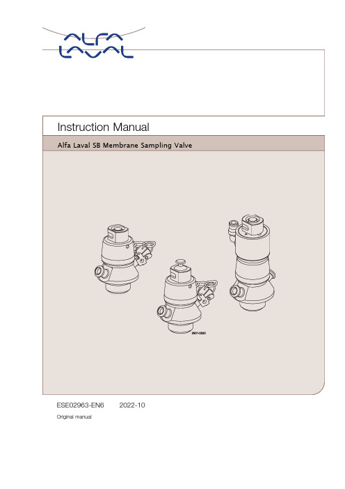
Argus阀门操作手册
阿尔法拉瓦尔 SB 膜样品抽取阀门操作手册说明书

Alfa Laval SB Membrane Sampling Valve
ESE02963-EN6
Original manual
2022-10
Table of contents
The information herein is correct at the time of issue but may be subject to change without prior notice
Designation
SB Membrane Sample Valve
Type
is in conformity with the following directives with amendments: - The Supply of Machinery (Safety) Regulations 2008
The person authorised to compile the technical file is the signer of this document.
Global Product Quality Manager
Title
Kolding, Denmark
Place
2022–10–01
Date (YYYY-MM-DD)
Signature
5
2 Safety
Unsafe practices and other important information are emphasised in this manual. Warnings are emphasised by means of special symbols.
2.1. Important information ............................................................................. 6 2.2. Warning signs ..................................................................................... 6 2.3. Safety precautions ................................................................................ 7 3. Installation .................................................................................... 8 3.1. Unpacking/delivery ............................................................................... 8 3.2. General installation ................................................................................ 8 3.3. Valve assembly .................................................................................... 9 3.4. Recycling information ............................................................................. 11 4. Operation ..................................................................................... 12 4.1. Operation .......................................................................................... 12 4.2. Sterilisation with alcohol .......................................................................... 13 4.3. Sterilisation with steam ........................................................................... 14 4.4. Sampling ........................................................................................... 15 5. Maintenance .................................................................................. 17 5.1. General maintenance ............................................................................. 17 6. Technical Data ............................................................................... 21 6.1. Technical data ..................................................................................... 21 7. Parts List and Service Kits ................................................................... 22 7.1. Membrane Sampling Valve, manual ............................................................ 22 7.2. Membrane Sampling Valve, manual & micro port ............................................. 24 7.3. Membrane Sampling Valve, pneumatic ......................................................... 26
阀门操作规程

阀门操作规程一、引言阀门是工业生产中常见的一种控制装置,用于控制流体的流量、压力和流向。
为了确保阀门的正常运行和安全使用,制定阀门操作规程是必要的。
本文将详细介绍阀门操作规程,包括操作前的准备、操作过程中的注意事项以及操作后的处理。
二、操作前的准备1. 检查阀门的安装位置和连接管道的状态,确保无异常情况。
2. 根据阀门的类型和规格,选择适当的工具和设备,如扳手、螺丝刀、液压设备等。
3. 检查阀门的密封性能,确保无泄漏现象。
4. 根据工艺要求,确定阀门的开启或者关闭方向。
三、操作过程中的注意事项1. 操作前应戴好个人防护装备,如安全帽、防护眼镜、耳塞等。
2. 操作时应注意阀门的工作压力和温度范围,避免超过其承受能力。
3. 操作时应轻力操作,避免过度用力或者猛力操作,以免损坏阀门。
4. 操作过程中应注意阀门的开启或者关闭速度,避免产生冲击或者压力波动。
5. 操作过程中应注意观察阀门的运行状态,如有异常应及时住手操作并报告。
6. 操作过程中应及时记录阀门的开启或者关闭时间、角度或者位移等参数。
四、操作后的处理1. 操作完成后,应关闭操作设备,如手动操作阀门时,应将手轮或者手柄归位。
2. 检查阀门的密封性能,确保无泄漏现象。
3. 清理阀门周围的工作区域,确保无杂物和障碍物。
4. 及时报告操作结果和阀门的异常情况,如泄漏、损坏等。
5. 定期对阀门进行维护和保养,保证其正常运行和使用寿命。
五、总结阀门操作规程是保证阀门正常运行和安全使用的重要保障。
操作人员应严格按照规程进行操作,遵守操作过程中的注意事项,确保阀门的可靠性和安全性。
同时,定期进行维护和保养,及时处理异常情况,可以延长阀门的使用寿命,提高生产效率。
以上是阀门操作规程的详细内容,希翼对您有所匡助。
如有任何疑问或者需要进一步了解,请随时联系我们。
阀门操作规程

阀门操作规程前言阀门是工业控制系统中常见的设备,用于控制和调节流体的流量、压力、方向等参数。
正确的阀门操作可以有效地保证系统的安全运行和工作效率。
本文档旨在规范阀门的操作,减少人为操作失误,并提高安全生产水平。
通用操作流程阀门的操作过程一般包括以下几个步骤:1.判断阀门型号和参数2.确认阀门位置3.进行操作4.检查操作效果5.记录操作情况下面将针对每个步骤详细说明。
1. 判断阀门型号和参数在进行阀门操作前,应先确定阀门的类型、规格和参数,例如阀门的材质、阀门公称通径(DN)、压力等级、温度范围等信息。
这样有利于正确选择适合的操作工具和阀门操作模式,并避免因为操作错误导致的设备故障和安全事故。
2. 确认阀门位置确认阀门的位置是阀门操作的重要步骤。
通常情况下,可以通过观察阀门指示器(手柄、旋钮等)的位置和状态来确定阀门开启、关闭、中间位置等状态。
如需更精确的确认,可以使用压差、温差等检测方法来确定阀门位置。
3. 进行操作针对不同的阀门类型和工作要求,阀门操作方法也各不相同。
例如球阀、闸阀、截止阀等常见的阀门类型,可以分别选择旋转或推拉、回转、提升等不同的操作方式。
操作时,应使用正确的工具和方法,严格按照规定的操作程序进行。
4. 检查操作效果操作后需要对阀门的状态进行检查,确保阀门满足工作要求。
例如,开启阀门后需要检查流量、压力等参数是否正常,防止因为操作不当而导致的泄露、过压等危险情况。
5. 记录操作情况操作过程中需要记录阀门的操作时间、操作人员、操作内容及其效果等信息,并在操作后及时将记录报告给有关部门,以便进行管理和监督。
如果发现有疑问或异常情况,应及时向上级汇报和寻求帮助。
阀门不同类型操作方法1. 手动截止阀手动截止阀又称止回阀,是一种常用的阀门类型。
操作手段通常是在阀门手柄上应用人力,使阀门轴向运动,完成截止、开启等动作。
截止阀操作流程如下:1.确认截止阀门的位置,检查手柄位置,确保阀门开启或关闭状态。
阀门执行器手动使用说明

阀门执行器手动使用说明手轮机构与气动执行器配套使用,当气源信号出现故障,阀门无法开启、关闭,或固定在某一位置时,就必须通过手轮来完成。
1.阀门的开启方向,通常是逆时针表示打开,顺时针表示阀门关闭。
因此,开关阀门时要注意方向。
2.阀门上的手轮、手柄是按正常人力设计的,因此,在阀门使用上规定,不允许操作者借助杠杆和长扳手开启或关闭阀门。
3.当手轮全开后,应倒转少许,使螺纹之间严紧,以免松动损伤。
4.若手轮是做限位用的,应在预定位置,检修时可借助标尺和记号记住它们全开和全关位置,这样可以避免全开时顶撞死点。
5.阀门出厂时,不论气动执行器是正作用还是反作用,手轮都在开启状态,并都用锁母锁死,以免操作人员误操作把手轮关下去,阀门无法打开或达不到所需流量,造成不必要的事故和损失。
6.操作人员在用手轮操作前,先将手轮锁母松掉,再进行操作,操作完成后,如无特殊说明,一定要把手轮打开,并用锁母锁死。
电动执行器手动操作说明实物照片及标识IQ系列电动执行器手轮图1(现场图片(1)手动/自动手柄(2)手轮手动/自动手柄手轮操作步骤说明侧装手轮压下手动/自动手柄(1),使其处于手动位置。
旋转手轮(2)以挂上离合器, 时松开手柄,手柄将自动弹回初始位置,手轮将持啮合状态, 直到执行器被电动操作, 手轮将自动脱离,回到电机驱动状态。
如果需要,可用一个带6.5mm铁钩的挂锁将离合器锁定在任何状态。
手轮机构不可以作为限位机构使用。
阿卡8C系列手动操作说明示例实物照片及标识812型顶装手轮(1)手轮(2)定位销(3)导杆(4)丝母操作步骤说明顶装手轮812型的顶装手轮机构操作时拔起定位销钉(2)。
812型的顶装手轮机构主要有手轮(1),定位销(2)、丝母(4)及导杆组件(3)组成。
逆时针旋转手轮时,丝母带动导杆向上使阀门打开;顺时针旋转手轮时,丝母带动导杆向下使阀门关闭。
阀门正常使用时,故障关阀门,观察阀门标尺指示是否在全关位置,确定手轮在空挡位置,定位销完全回位。
海洛斯操作手册(说明书)

HIROSS恒温恒湿机房精密空调操作手册HIMOD系列北京****科技有限公司技术部2009年01月01日目录第一章HIMOD系列海洛斯空调概述 ..................................................................................................1.1型号多 ................................................................................................................................................1.2控制技术先进 ....................................................................................................................................1.3制冷系统 ............................................................................................................................................1.4送风系统 ............................................................................................................................................1.5加湿系统 ............................................................................................................................................1.6加热系统 ............................................................................................................................................1.7其它 .................................................................................................................................................... 第二章HIMOD系列海洛斯空调型号含义 .......................................................................................... 第三章有关空调的一些资料 ..................................................................................................................3.1气流组织方式 ....................................................................................................................................3.2盖板纽开启方式 ................................................................................................................................3.3空调重量 ............................................................................................................................................3.4机组尺寸及维护空间 ........................................................................................................................ 第四章制冷循环管路示意图 ..................................................................................................................4.1风冷却(A型).................................................................................................................................4.2水冷却(W型)................................................................................................................................4.3双冷源(D型).................................................................................................................................4.4单系统(C型).................................................................................................................................4.5双系统(C型)................................................................................................................................. 第五章调速风机调速接线示意图 .......................................................................................................... 第六章MICROFACE概述 ...................................................................................................................6.1概述 ....................................................................................................................................................6.2Microface面板简介............................................................................................................................6.3LCD液晶显示屏介绍 ........................................................................................................................ 第七章MICROFACE面板的操作 ....................................................................................................... 第八章控制器的使用 ..............................................................................................................................8.1控制器(HIROMATIC)概述..........................................................................................................8.2控制器的操作 ....................................................................................................................................8.3菜单结构 ............................................................................................................................................ 第九章日常维护及特殊维护 ..................................................................................................................9.1日常维护 ............................................................................................................................................9.2特殊维护 ............................................................................................................................................ 第十章常见报警及处理 ..........................................................................................................................10.1低压报警 ..........................................................................................................................................10.2高压报警 ..........................................................................................................................................10.3加湿报警 ..........................................................................................................................................10.4失风报警 ..........................................................................................................................................10.5电加热过热报警 ..............................................................................................................................10.6显示器发黑 ......................................................................................................................................10.7空调不制冷 ......................................................................................................................................附录1:参数列表 ...................................................................................................................................附录2:报警内容列表 ...........................................................................................................................附录3:各菜单项含义 ...........................................................................................................................第一章HIMOD系列海洛斯空调概述HIMOD系列海洛斯空调(HIMOD空调)是当今世界上最先进的机房专用恒温恒湿机房专用精密空调。
Argus阀门操作手册

Argus阀门操作手册
一、 阀门处于DCS自动操作
1、首先保证气源压力在5Bar;
2、手轮操作机构的离合器手柄处于“OFF”状态,同时保证离合器限位到位;
二、 阀门处于现场手动操作
1、关闭阀门供气气源的手动阀门;
2、调节过滤减压阀压力调节旋钮,使压力表的压力指示为“0”;
3、手轮操作机构的离合器手柄处于“ON”状态,同时保证离合器限位到位;
4、现场即可使用手轮开关阀门;
5、当现场手动操作完阀门以后,阀门必须使用手轮操作机构把阀门关闭;
6、离合器手柄由“ON” “OFF”,同时保证离合器限位到位;
7、此时阀门由手动变为自动;
关于手轮操作机构的使用注意事项:
1、当旋转离合器手柄由“ON” “OFF”或“OFF” “ON”时,离合器限位
必须被拉出来;
2、在旋转离合器手柄时,如果比较吃力,可以左或右多旋转几圈手轮,这时可
以感觉到旋转离合器手柄比较容易;
3、当转动离合器手柄,可以把离合器限位松开,当离合器手柄到位时,可以听
到离合器限位到位的响声,同时离合器限位由高变低;
4、手动操作阀门时,必须关闭气源,同时通过过滤减压阀排除气缸内的气体;
5、自动操作时,严禁把手轮操作机构切换到手动状态;
6、阀门由手动切换到自动时,阀门必须处于关闭状态;
7、阀门在手动操作时,阀门不能在半开半关状态下切换到自动操作;。
阀门基础操作规程

阀门基础操作规程5.1 阀门阀门安装好后,操作人员必须在熟悉和掌握阀门传动装置的结构和性能,正确识别阀门方向,开度标识,指示信号的前提下,调节和操作阀门。
5.1.1 手动阀门的操作5.1.1.1 手动阀门的手轮(手柄)旋转方向通常情况是顺时针为关闭,逆时针为开启,但也有个别阀门开启与上述开启相反,因此,操作前应注意检查启闭后再操作。
5.1.1.2 手动阀门上的手轮(手柄)是按正常人力设计的,未经有关技术人员许可,不允许操作者借助杠杆和长扳手开启或关闭阀门。
1)手轮、手柄的直径(长度)<320mm的,只允许一个人操作,直径(长度)≥320mm的手轮,允许两个人共同操作,或者允许一人借助适当的杠杆(一般不超过0.5m长)操作阀门。
但隔膜阀,夹管阀,非金属阀门是严禁使用杠杆或长扳手操作的,也不允许过猛关闭阀门。
2)隔膜阀、夹管阀、非金属阀门严禁使用杠杆或长扳手操作,否则容易损坏密封面,或扳断手轮(手柄)。
3)有的操作人员习惯使用杠杆和长扳手操作,认为关闭力越大越好,其实不然,这样会造成阀门过早损坏,甚至酿成事故。
5.1.1.3 启闭阀门,用力应该平稳,不可冲击(某些冲击启闭的高压阀门、撞击式手轮各部件已经考虑了这种冲击力与一般阀门不能等同),要慢慢拧动,不可开闭太快、过猛,发生水锤现象,避免因此损坏手轮(手柄)、阀杆,甚至压坏密封面。
5.1.1.4 闸阀和截止阀之类的阀门,关闭或开启到头(即到达下死点或上上死点)后要回转1/4~1/2圈,使螺纹更好密合,有利操作时检查,避免拧的过紧,损坏阀件。
5.1.1.5新安装的管道、设备、阀门,内面脏物、焊渣等杂物较多;常开阀门密封面上也容易粘有脏物,应采用微开方法,让高速介质冲走这些异物,再轻轻关闭,经过几次这样微开微闭便可冲刷干净。
5.1.1.6 较大口径或高压力的蝶阀、闸阀和截止阀,设有旁通阀的,开启时,应先打开旁通阀,待阀门前后压差减小后,再开启主阀门。
阀门操作规程

阀门操作规程阀门操作规程是指针对阀门的使用、维护和操作过程中应遵循的一系列规定和步骤。
本文将详细介绍阀门操作规程的标准格式,包括阀门操作的准备工作、操作步骤、注意事项和常见故障处理等内容。
一、阀门操作规程的准备工作1. 确定操作人员:操作人员应具备相关的技术知识和操作经验,并经过专业培训和考核。
2. 确定操作环境:操作环境应符合安全要求,无明火、易燃易爆物品等危险因素。
3. 准备必要的工具和设备:根据具体阀门类型和规格,准备好相应的工具和设备,如扳手、润滑剂等。
二、阀门操作规程的操作步骤1. 检查阀门状态:在操作阀门之前,先检查阀门的状态,确保阀门处于关闭状态。
2. 准备操作区域:清理操作区域,确保无杂物和障碍物,确保操作空间充足。
3. 操作前的准备:佩戴个人防护装备,如安全帽、防护手套等。
4. 开启阀门:根据具体阀门类型,使用相应的工具逆时针旋转或上推阀门手柄,使阀门逐渐打开。
5. 检查阀门工作状态:开启阀门后,检查阀门的工作状态,确保阀门完全打开。
6. 操作阀门:根据需要,根据具体情况调整阀门的开度,控制介质流量。
7. 关闭阀门:根据具体阀门类型,使用相应的工具顺时针旋转或下推阀门手柄,使阀门逐渐关闭。
8. 检查阀门关闭状态:关闭阀门后,检查阀门的关闭状态,确保阀门完全关闭。
9. 清理操作区域:操作完成后,清理操作区域,将工具和设备归位。
三、阀门操作规程的注意事项1. 操作前应仔细阅读阀门的使用说明书,了解阀门的特点和使用要求。
2. 操作人员应按照操作规程进行操作,严禁违规操作和私自改动阀门设置。
3. 操作人员应保持操作区域的整洁和干净,防止杂物或污染物进入阀门内部。
4. 在操作阀门时,应轻力操作,避免使用过大的力量造成阀门损坏。
5. 定期检查阀门的工作状态和密封性能,如发现异常应及时处理。
四、阀门操作规程的常见故障处理1. 阀门漏气:检查阀门密封面是否损坏,如需要更换密封垫片或修复密封面。
气动硬密封球阀使用说明

气动硬密封球阀使用说明
气动硬密封球阀是一种常用的流体控制设备,通常用于管道系
统中,下面我将从不同角度来回答你的问题。
1. 安装和连接,首先,确保阀门和管道的连接口清洁,无杂物。
然后,根据阀门和管道的尺寸,选择合适的连接方式,通常包括螺
纹连接、对焊连接或法兰连接。
安装时要注意阀门的流向,确保阀
门安装正确。
2. 操作方法,气动硬密封球阀是通过气动执行器来控制的,通
常需要接入气源。
打开或关闭阀门时,通过控制气源的压力来控制
阀门的开合。
可以通过手动操作或远程控制来实现阀门的开关。
3. 注意事项,在使用气动硬密封球阀时,需要注意阀门的工作
压力范围,不要超过其额定压力。
另外,定期检查阀门的密封性能,确保阀门的密封圈完好,避免泄漏。
同时,阀门在长期使用后,需
要进行定期的维护和保养,包括润滑和清洁。
4. 应用范围,气动硬密封球阀适用于各种工业管道系统,包括
化工、石油、制药、冶金等领域。
其优点包括密封性好、耐腐蚀、
使用寿命长等特点,适用于对流体流动有严格要求的场合。
总的来说,使用气动硬密封球阀时,需要注意安装连接、操作方法、注意事项和应用范围,确保阀门的正常运行和安全使用。
希望以上信息能够对你有所帮助。
阀门操作规程

阀门操作规程一、引言阀门是工业生产中常见的一种设备,用于控制流体的流量、压力和方向。
为了确保阀门的正常运行和安全使用,制定阀门操作规程是非常必要的。
本文将详细介绍阀门操作规程的内容,包括阀门的分类、操作步骤、注意事项等。
二、阀门分类根据不同的工作原理和结构特点,阀门可以分为以下几类:1. 切断阀:用于完全切断流体的流量,如截止阀、球阀等。
2. 调节阀:用于调节流体的流量和压力,如调节阀、蝶阀等。
3. 安全阀:用于保护设备和管道不受过压的损害,如安全阀、溢流阀等。
4. 止回阀:用于防止流体逆流,如止回阀、逆止阀等。
三、阀门操作步骤1. 准备工作:a. 确认阀门的类型和用途。
b. 检查阀门的外观和密封性能,确保无损坏。
c. 清理阀门周围的杂物和污垢,确保操作空间和安全。
d. 检查阀门所在的管道系统是否停止供料或排空。
2. 开启阀门:a. 根据阀门的类型,确定正确的开启方向。
b. 缓慢旋转或推动阀门手柄或操作杆,直到阀门完全开启。
c. 检查阀门是否完全打开,确保流体能够顺畅通过。
3. 关闭阀门:a. 根据阀门的类型,确定正确的关闭方向。
b. 缓慢旋转或推动阀门手柄或操作杆,直到阀门完全关闭。
c. 检查阀门是否完全关闭,确保流体无法通过。
4. 调节阀门:a. 根据需要调节的流量或压力,逐步旋转或推动阀门手柄或操作杆。
b. 观察流体的变化,并根据实际情况进行微调,直到达到所需的流量或压力。
四、阀门操作注意事项1. 操作人员应熟悉阀门的类型、结构和工作原理,遵守操作规程。
2. 在操作阀门之前,应仔细检查阀门的外观和密封性能,确保阀门无损坏。
3. 操作阀门时,应根据阀门的类型和用途确定正确的开启或关闭方向。
4. 操作阀门时,应缓慢旋转或推动阀门手柄或操作杆,避免过快或过用力。
5. 在操作阀门时,应随时观察流体的变化,确保阀门的开启或关闭效果。
6. 在调节阀门时,应逐步进行微调,避免突然调节引起流体的剧烈变化。
阀门操作手册

1.目的为使我公司的阀门能够规范进行操作,特制订本规程。
2.适用范围适用于公司的球阀(手动、电动)、旋塞阀、节流截止放空阀的操作。
3.职责3.1 运行保障部负责监督本规程的执行情况。
3.2 各分子公司遵照本规程进行相应的操作。
4.操作步骤4.1 球阀开启操作4.1.1手动球阀的开启4.1.1.1双手握住手轮按照阀门开关指示器上的方向指示(一般为逆时针方向)转动,同时应密切注意蜗轮-蜗杆传动装置的有无转动、有无异常声响。
4.1.1.2按照阀门上的开关指示确定开到位。
4.1.1.3开到位后手轮往回转一点,以保证轮齿啮合部分不再处于受力状态。
4.1.2电动球阀的开启4.1.2.1打开红色转换开关的锁定装置,将红色转换开关打到“4.1.2.2把手柄扳到手动位置;4.1.2.3按逆时针方向转动手轮,将阀门开到5%,待阀门前后压力平衡后,朝“确认阀门全开后,把红色转换开关打到“位置,将锁定装置锁好。
4.2 球阀关闭操作4.2.1手动球阀的关闭4.2.1.1按照开关指示器的方向旋转操作(柄)手轮;4.2.1.2按照开关指示确定开关到位。
4.2.1.3关到位后手轮往回转一点,以保证轮齿啮合部分不再处于受力状态。
4.2.2电动球阀关闭操作4.2.2.1打开红色转换开关的锁定装置,将转换开关打到“4.2.2.2朝“4.2.2.3把红色转换开关打到”位置,将锁定装置锁好。
4.3旋塞阀的操作4.3.1旋塞阀的开启4.3.1.1双手握住手轮按照阀门开关指示器上的方向指示(一般为逆时针方向)转动。
4.3.1.2 按照阀门上的开关指示确定开到位。
4.3.1.3开到位后手轮往回旋转半圈,以保证轮齿啮合部分不再处于受力状态。
4.3.2旋塞阀的关闭4.3.2.1 按照开关指示器的方向旋转(一般为逆时针方向)手轮。
4.3.2.2按照开关指示确定开关到位。
4.3.2.3开到位后手轮往回旋转半圈,以保证轮齿啮合部分不再处于受力状态。
4.3.3 旋塞阀开关中的注意事项4.3.3.1 操作在正常情况下应一个人不用加力杆可正常开关。
阿尔特罗尼克燃气控制阀操作手册说明书

ALTRONIC GAS CONTROL VALVE OPERATING MANUAL 690154 SERIES FORM GCV1 OM 12-04 WARNING: DEVIAT ION FROM T HESE INST ALLAT ION INST RUCT IONS MAY LEAD T O IMPROPER ENGINE OPERAT ION WHICH COULD CAUSE PERSONAL INJURY T O OPERATORS OR OTHER NEARBY PERSONNEL.1.0 OVERVIEW1.1This manual provides installation instructions and maintenance information for the AltronicGas Control Valve, models 690154-1 and 690154-2. It is recommended that the user read this manual in its entirety before commencing operations.It is not our intention to instruct others on how to design control systems, nor can we assume responsibility for their safe operation. This advice is intended to help the end user install the Altronic Gas Control Valve in such a manner to reduce the risk of accident to personnel or to equipment.Do NOT attempt to operate, maintain, or repair the fuel control valve until the contents of this document have been read and are thoroughly understood.1.2The Altronic Gas Control Valves are normally used with natural gas. Natural gas and air,when combined together,become very combustible and when contained within an enclosure, such as a gas engine or its exhaust system, can explode in a violent manner when ignited.It is necessary to always use extreme caution when working with any fuel system. The control systems used with gas engines or other similar machines should always be designed to be “fail-safe”.1.3The Gas Control Valve is NOT a shutoff valve. Shutoff valves must be used in addition to thecontrol valve. The fuel system should be designed in such a way that:-no failure of a single component will cause the fuel system to admit fuel to the engine when the engine has been shutdown, and-no single failure can result in grossly over-fueling the engine when attempting to start.WARNING:Failure to follow the above rules may lead to serious damage to equipment or to personnel.1.4The two versions, 690154-1 and 690154-2, differ in the length of the internal piston toaccommodate different gas flow rates.Valve 690154-1 is recommended for use on gas engine applications from 250 HP to 1,000 HP.Valve 690154-2 is recommended for use on applications below 250 HP.1.5Maximum gas working pressure is 40 psig. Gas pressure at the valve must NOT exceedthis rating at any time.2.0 INSTALLATION2.1The Gas Control Valve should be inspected immediately after unpacking. Check for anydamage that may have occurred during shipping. If there are any questions regarding the physical integrity of the valve,contact the distributor or Altronic, Inc.NOTE: If possible, keep the original shipping container. If future transportation or storage of the valve is necessary, this container will provide the optimum protection.2.2The Gas Control Valve is designed to be installed on natural gas fired, reciprocating engines.It is a flow-control device that responds directly to the control output of the Altronic EPC-100 and EPC-150 series of Air Fuel Ratio controllers. Additionally, by the use of a special adaptor device,Altronic P/N 691156-1, the valve can be made to control based upon a 4 to 20 mA signal from a general purpose controlling device such as a PLC. In all cases the valve is installed between the fuel supply pressure regulator and the carburetor and is used to throttle the fuel available to the engine. When considering where to place the Gas Valve, choose a location away from any extreme sources of heat. Operating ambient temperature is–40°F to +185°F (–40°C to +85°C). Do not expose the valve to temperatures higher than indicated here.3.0 MOUNTING THE FUEL CONTROL VALVE3.1In order to control the air/fuel ratio, the electronically controlled valve is connected in seriesbetween the regulator and carburetor or mixer. The valve should be installed as close to the fuel inlet of each carburetor or mixer as possible.The distance from the valve to the carburetor inlet should not exceed 12 pipe diameters in length. The preferred mounting of the valve would be in the vertical position, with the Flow arrow pointing up or down. Horizontal mounting of the valve is acceptable as long as the valve is NOT installed with the control cable connector facing downward. This is necessary to avoid the collection of condensation in the electronics housing. See FIG. 1 for dimensional details.3.2If possible, gas connection piping should be of the same diameter as that currently in use.The 690154 series valves have 1.5 inch NPT threads. In some applications, the threaded connection to the valve body may require the use of thread adapters. If adapters are used, proper plumbing procedures must be followed.3.3Each control valve is connected to the EPC-100 or EPC-150 using the 693005-x cable. Thiscable has connectors on both ends and in unshielded installations these connectors are simply plugged into the valve and the EPC unit. If it is desired to enclose the cable in conduit, this can be easily accomplished by cutting the 693005 cable in half. The cables are color coded and must be reconnected inside a junction box with each wire color matching. This cable must not be run in the same conduit as the ignition primary or other wires.A distance of 4 to 6 inches should be maintained between EPC-100 or EPC-150 wiring and other engine wiring. Note that the upper connector on the EPC-100 or EPC-150 controls the stepper valve for single control channel applications and the left bank valve on V-engines.4.0 POWER SUPPLY4.1The circuitry of the valve is powered directly by the EPC-100, EPC-150 or the output of theStepper Motor Controller 691156-1. No additional external power source should ever be connected to the valve.5.0 FLOW CHARACTERISTICS5.1See the flow capacity curve, FIG. 3in the drawings section.6.0 GAS VALVE SERVICE AND REPAIR OVERVIEW6.1The Gas Valve has been designed to provide reliable operation with a minimum amount ofmaintenance. To ensure optimum performance, periodic inspection and cleaning is necessary. Preventative maintenance issues can be integrated into the current maintenance schedule of the engine. Most maintenance requires little effort and minimal downtime of the valve. Corrective maintenance is to be done when the Gas Control Valve begins to behave erratically. Procedures have been generated to cover most minor issues.•External Visual Inspection – Inspect the exterior of the Gas Control Valve for loose connections, frayed wires or structural damage.•Cleaning – Exterior cleaning will aid in the visual inspection of the external casing and ensure good connections. Mild soapy water can be used as a cleaning agent.•Maintenance Log – To facilitate troubleshooting and to establish service schedules, a maintenance log should be kept on the Gas Control Valve.Throughout this manual, service parts will be identified by the figure number and item number assigned in the parts list. Items will be referred to by the figure number followed by a hyphen and the item number that it refers to. For example, (2-5) and its position on the Gas Control Valve can be found by locating item 5 on FIG. 2 and looking for its description and part number as identified in the table.7.0 SERVICING THE GAS CONTROL VALVE7.1The Altronic Gas Control Valve is set from the factory and generally does not needadjustment, however periodic maintenance may be needed depending on the service application and quality of the fuel passing through the valve. By following the recommended mounting positions and supplying clean gas this valve will provide excellent service.7.2The following lists the service kits available for the Gas Control Valve.•Motor/Connector/Piston Assembly P/N 680003-1 (690154-1 Valve)P/N 680003-2 (690154-2 Valve) Other parts are available as individual items.8.0 DISASSEMBLY OF THE GAS CONTROL VALVE8.1This section covers the disassembly of the fuel control valve for purposes of field service ormaintenance. This valve was designed to be serviceable while connected to the gas pipeline providing that the gas flow has been shut off to the valve.Failure to shut off the gas flow can cause a very dangerous situation. If servicing is to be done with the valve removed from the gas pipeline, then it is recommended that a clean flat work surface be prepared and the proper tool be made available.8.2This is a recommended tool list to disassemble the 690154 series Gas Control Valves:•#2 Phillips Head screwdriver•5/16" socket with ratchet and short extension•5/32" T - handle hex wrench (Allen wrench)8.3With the stepper motor in its fully retracted position (valve fully open), remove the four 8-32seal screws (2-7) that secure the connector to the cover. Next remove the six 10-24 hex head screws (2-9) and lock washers (2-3) that fasten the cover plate (2-6) to the valve body (2-1).Note gasket (2-5) between connector and cover. There is also a gasket (2-8) between the cover plate and the valve body.8.4With the cover (2-3) removed, the inner workings of the valve are now exposed. Keep thisarea free from contaminants such as excessive dirt and moisture. Removing the two socket head cap screws (2-4) and the lock washers (2-3) will allow you to remove the stepper Motor/Connector/Piston Assembly (2-2) from the valve body (2-1). Having available a spare Motor/ Connector/Piston Assembly (2-2) will minimize downtime.9.0 REASSEMBLY OF THE GAS CONTROL VALVE9.1To reassemble the valve, follow the instructions given.9.2Replace the Motor/Connector/Piston Assembly (2-2) into the valve body (2-1). Secure themotor using the two socket head cap screws (2-4) and lock washers (2-3).9.3Replace the connector into the cover plate (2-6), taking care to properly mount the connectorgasket (2-5) between the connector and the cover. Secure the connector to the cover using the four 8-32 phillips head seal screws (2-7).9.4Attach the cover plate (2-6) to the valve body (2-1), taking care to properly mount the coverplate gasket (2-8) between the valve body and the cover plate. Secure the cover plate using the six 10-24 hex head screws (2-9) and lock washers (2-3). See tightening sequence and torque specification on FIG. 2.9.5Before returning the valve to service, the valve should be throughly leak tested using a soapywater solution.Brush a small amount of this solution onto the area to be tested. A constant bubbling of the liquid indicates a leak. Do not submerge the valve in the test solution.Carefully check the area around the cover gasket and around the connector.FIG. 2 - PARTS IDENTIFICATIONITEM NO.QUANTITY PART NO.DESCRIPTION11 610651Valve Body, Machined21 680003-1Motor-Piston Assembly (690154-1) 680003-2Motor-Piston Assembly (690154-2)31 901004Lockwasher #1041 902628Screw 8-32 x 1/2" Socket Hd 51 501335Gasket, Connector61 610609Cover Plate71 902632Screw 8-32 x 3/8" Seal Rd Hd 81 610610Gasket, Cover Plate91 902472Screw 10-24 x 5/8" Hex Hd。
阿尔法拉瓦尔独特SSSV单座阀门说明说明书

Benefits•Exceptional valve hygiene and durability•Superior cleanability – smooth inner valve body withoutcrevices•Extended seal life due to the defined seal compression •Enhanced product safety due to the static seal leakdetection•Protection against full vacuum due to the double lip seal •Fast-actingStandard designThe Alfa Laval Unique SSSV is available in a one- or two-body configuration, with easy-to-configure valve bodies, elastomer-free PVDF plugs, static sealing, actuator or manual mechanism, and clamp rings. It is available in DN/OD 12.7 mm (½”) and 19 mm (¾”) versions.The valve is assembled when delivered. Valve housing is either supplied with standard weld or clamp ends, and it is assembled by means of clamp rings. The piston and valve plug in PVDF have threaded connections.The Unique SSSV can be configured as a manually operated valve or a pneumatic valve. It can also be configured as a shutoff valve or as a changeover valve, each with two to five ports.The valve seals are optimized for durability and long service life through a defined compression design. The actuator is connected to the valve body using a yoke, and all components are assembled with clamp rings.The valve can also be fitted with the Alfa Laval ThinkTop V50 and V70 for sensing and control of the valve.Using the Alfa Laval Anytime configurator, it is easy to customize to meet virtually any process requirement.Working principleThe Alfa Laval Unique SSSV is operated either manually by means of cranking mechanism or by means of compressed air from a remote location. For a pneumatic valve, the actuator smooths operation and protects process lines against pressure peaks. The valve can be controlled using an Alfa Laval ThinkTop®.CertificatesTECHNICAL DATAMin. product pressure:Full vacuumAir pressure:100 to 700 kPa (1 to 7 bar)Valve Body Combinations2200-0179200300210220310320Actuator function•Pneumatic downward movement, spring return (NO)•Pneumatic upward movement, spring return (NC)•Manually operatedStop valve/Change-over valve:0.06 x Air pressure (bar)Actuator function:NO and NCPHYSICAL DATAOther steel parts:Stainless steel 1.4307 (304L)External surface finish:Semi-bright (blasted)Internal surface finish:Ra ≤ 0.5µm Product wetted seals:EPDM Other seals:NBR Plug:PVDFOPTIONS •Adapter for IndiTop, ThinkTop and ThinkTop Basic•Control and Indication: IndiTop, ThinkTop or ThinkTop Basic •Product wetted seals of HNBR or FPM•Stainless steel seal disc replacing standard lip seal •Clamp with wingnut •Clamp connectionNote!For further details, see also ESE01563 and instruction IM 70860Dimensions (mm) Valve dimensionsFigure 1. Stop valveFigure 2. Change over valveFigure 3. Manual stop valveFigure 4. Manual change-over valve1A2179.2182.2116.7123.7 A3200.2209.2141.7150.7 A4207.2220.2148.7161.7 C32.338.132.338.1 OD12.719.012.719.0 ID9.515.89.515.8 t 1.6 1.6 1.6 1.6 E129.829.929.829.9 E245.045.045.045.0 F17.011.07.011.0 F27.011.07.011.0 H57.057.035.035.0 Weight (kg) - Stop valve 1.07 1.100.50.53 Weight (kg) - Change-over valve 1.36 1.410.80.85(900-233)Please note!Opening/closing time will be affected by the following:•The air supply (air pressure)•The length and dimensions of the air hoses•Number of valves connected to the same air hose•Use of single solenoid valve for serial connected air actuator functions •Product pressure.Air Connections Compressed air:R 1/8" (BSP), internal threadPressure drop/capacity diagrams Stop valve∆P [kPa]A = 12.7B = 19.0Q [m³/h)∆P [kPa]A = 12.7B = 19.0Q [m³/h) Change-over valveA = 12.7B = 19.0Q [m³/h)A = 12.7B = 19.0Q [m³/h)∆P [kPa]A = 12.7B = 19.0Q [m³/h)∆P [kPa]A = 12.7B = 19.0Q [m³/h)A = 12.7B = 19.0Q [m³/h)A = 12.7B = 19.0Q [m³/h)Note!For the diagrams the following applies:Medium: Water (20 °C).Measurement: In accordance with VDI2173Pressure drop can also be calculated in Anytime configurator.Pressure drop can also be calculated with the following formula:Q = Kv x √ΔpWhereQ = Flow in m3/h.Kv = m3/h at a pressure drop of 1 bar (see table above).Δ p = Pressure drop in bar over the valve.Where Q = Flow in m3/h.Kv = m3/h at a pressure drop of 1 bar (see table above).Δ p = Pressure drop in bar over the valve.2.5" shut-off valve, where Kv = 111 (See table above).Q = Kv x √Δp40 = 111 x √Δp0.13 bar(This is approx. the same pressure drop by reading the y-axis above)Pressure data for Unique Small Single Seat ValveFigure 5. 1Figure 6. 2Figure 7. 3Figure 8. 4Shut-off and change-over valvesFigure 6. 22NO 2.0-3NOMin. 10.03.04NO Min. 10.0 Figure 7. 32NC9.0-3NC Min. 10.0Min. 10.0 Figure 8. 4NC Min. 10.0Min. 10.0Figure 9. 5Figure 10. 6Figure 11. 7Figure 12. 8Stop and change-over valveFigure 10. 62NO9.0-3NO Min. 10.0 6.04NO-Min. 10.0Figure 11. 72NC Min. 10.0Min. 10.0Figure 12. 8NC Min. 10.0Min. 10.0This document and its contents are subject to copyrights and other intellectual property rights owned by Alfa Laval Corporate AB. No part of this document may be copied, re-produced or transmitted in any form or by any means, or for any purpose, without Alfa Laval Corporate AB’s prior express written permission. Information and services provided in this document are made as a benefit and service to the user, and no representations or warranties are made about the accuracy or suitability of this information and these services for any purpose. All rights are reserved.200004000-3-EN-GB© Alfa Laval Corporate AB How to contact Alfa LavalUp-to-date Alfa Laval contact details for all countries are always availableon our website at 。
格罗夫球阀操作规程

格罗夫球阀操作规程
1 操作指导
1.1打开阀门应使阀杆逆时针旋转90度停止。
1.2关闭阀门应使阀杆顺时针旋转90度停止。
1.3阀球的旋转可通过手轮、电动执行机构或电液执行机构来实现。
1.4阀门安装有执行器,操作阀门之前,请仔细阅读该执行器的操作规程。
1.5在任何一种情况下,(无论手轮操作,电动执行机构操作或电液执行机构操作)阀
门均已在出厂前对阀位进行了设定以保证阀门从全开到全关的90度正确的旋转,因此不要改变这些设定。
2 注意事项
2.1格罗夫球阀是开/关两位阀门,应确保阀门在使用时总处于全开或全关的位置。
标
准的格罗夫球阀不应当作流量调节阀使用。
2.2阀门在运行使用中可能会有沉积物或其他杂质。
在下列情况下,可能会损坏阀门。
•如果杂质阻碍阀门全关而使阀门处于节流状态,可能损坏球体或O形密封环。
•如果杂质进入球体和阀座之间,可能会损坏球体或阀座表面。
2.3排污是防止杂质损坏球阀的最佳办法。
如果出现下述情况,可以对球阀进行排污:•当阀门不能关闭时。
•在寒冷季节来临之前。
•清洗管线之后。
•水压试验之后。
2.4在正常运行的条件下,球阀不需要使用密封脂。
2.5根据操作频率和使用工况的严峻性定期对球阀进行润滑。
如不能定期对球阀进行润
滑,在如下情况下对阀门进行润滑:
•如操作球阀前,阀门处于全关位、全开位或中间位置,并且阀门长期未动作时。
•阀杆操作扭距加大时。
3 排污
3.1将球阀全关。
3.2缓慢拧开球阀底部的排污阀。
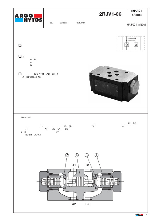
ARGO HYTOS 叠加式液控单向阀2RJV1-06 说明书

油液温度范围(NBR) for Fluid temperature range standard sealing (NBR) 油液温度范围(FPM) for Fluid temperature range Viton sealing (FPM) 粘度范围 range Viscosity
Maximum degree of fluid contamination 油液清洁度
叠加式液控单向阀
Pilot operated check valves sandwich plates
2RJV1-06
HA 5021 HN5021 1/2003
代替 Replaces
通径06,压力至320bar,流量至60L/min up to 60 L/min Size 06 · pmax up to 320 bar · Qmax
HN5021 配件 Spare Parts
Seal 密封 kit
型号 Type 标准-NBR Standard NBR
尺寸、数量 Dimensions, quantity
O-ring O形圈 14 x 1,78 NBR90 (2 pcs.) 18 x 2,65 NBR70 (2 pcs.) 9,25 x 1,78 (4 pcs.) Square ring 矩形圈 9,25 x 1,68 NBR70 (4 pcs.) Back-up ring 挡圈 17,83 x 22,19 x 1,14 (2 pcs.)
- leakfree closure in line B
Installation 4401-AB-03-4- q 安装尺寸按ISOdimensions to ISO 4401-AB-03-4-A
A和DIN24340-A6 and DIN 24 340-A6
阿托斯射胶阀使用手册

阿托斯射胶阀使用手册阿托斯射胶阀使用手册V1.0作者:阿托斯技术部一、为什么要选用DPZO-LS-PS-*73-V9DPZO-LS-PS-*73-V9/S/S/SP P比例伺服阀?DPZO-LS-PS-*73-V9/SP是注射缸控制专用的高速比例伺服阀,阀上专用的集成放大器具备注射油缸的速度与压力复合控制功能。
适用于定量泵+蓄能器系统的高速注塑机液压系统。
二、注射的基本动作,见下表:I快射射出一段射出二段射出三段射出四段射出五段备注位置position S1S2S3S4S…由电子尺测量后输入PLC进行位置确定流量flow Q1Q2Q3Q4Q…由PLC提供模拟量输出(0.5~10V)压力pressure P1P2P3P4P…由PLC提供模拟量输出要合理进行压力设定,否则,无法实现快射。
II保压压力pressure 根据材料需要或工艺需要,可通过时间函数来设定不同时段的压力由PLC提供模拟量输出,流量信号III背压压力pressure 根据材料需要或工艺需要,可通过时间函数来设定不同时段的压力,若用常规的比例阀,不能实现恒定的背压。
若使用V9阀后,当压力低于设定压力后,油缸前行;若A口压力高于设定压力后,油缸会自动后退,保持背压恒定。
由PLC提供模拟量输出IV快退松退一段松退二段松退三段松退四段松退五段位置position S1S2S3S4S…由电子尺测量后输入PLC进行位置确定流量flow Q1Q2Q3Q4Q…由PLC提供模拟量输出(-6~-10V)压力pressureP1P2P3P4P…由PLC提供模拟量输出三、比例伺服阀对控制器的控制信号的要求控制器应能提供两路独立的模拟量输出。
A:-10V~10V的速度控制信号,(-10V,0V)为松退,(0,10V)为射出;B:0~10V的压力控制信号;四、阀块安装时注意事项A:订货时,要注意比例阀的控制和泄漏方式,阿托斯标准机能为内控外泄(带/E选项为外控,/D选项为内泄),B:比例阀的A口一定要接在注射缸的与前行腔上。
威兰四通阀说明手册

INSTRUCTION MANUAL FOR SWITCH LIFT PLUG VALVE OPERATION提升式四通旋塞阀操作说明目录1.- 简介2.-手动模式和就地模式3.-自动模式3.1.自动控制系统描述3.2. -自动模式下限位销位置4.-自动模式1.- 简介此阀门操作时有三种模式:手动模式、就地模式、自动模式手动模式:通过执行机构上两个手轮来操作此阀门,但操作者必须熟悉此阀门的操作,在位置切换时,要求按预定程序来操作两个手轮。
这种模式是在执行机构失电的紧急情况下使用的,若旋塞到位后仍然转动手轮,会损坏阀门。
在手动模式下操作必须遵守以下步骤:z若控制盘没有电就把控制盘的开关钮打到关的位置。
z将每个执行器(电动头)的红色操作钮打到停止位置。
z用手轮操作时必须拉住离合杆,不然不动作。
就地模式:此模式下,操作者必须通过执行机构(电动头)上面的黑色旋钮来操作阀门,同时必须将限位销上到合适的位置。
例如:在就地模式下从A塔切换到B塔,首先要通过提升/回座执行器上的黑色旋钮来提升旋塞,等停止后,然后使用旋转执行器的黑色旋钮来旋转旋塞,等停止后,最后再用提升/回座执行器上的黑色旋钮来回座旋塞。
若在自动模式下,从A塔切换到B塔,只需按下控制盘上DRUM B键 (B塔)即可,控制盘会自动操作以上所有动作。
在就地模式下必须按以下步骤:z将控制盘开关键打到关的位置。
z将每个执行器(电动头)的红色操作旋钮打到就地模式位置。
自动模式:此模式下,控制盘自动来操作阀门。
它自动按程序控制两个执行器按一定顺序将旋塞从一个位置切到另一个位置。
有两种联锁(一种硬联锁,一种软联锁)防止旋塞回座后继续旋转,在自动模式下以下步骤必须遵守:z将旋塞切到A塔、B塔或旁路,必须将旋塞回座z通过执行器上的红色旋钮将执行器设在远控位置。
z根据需要将机械限位销放在合适位置。
z装上限位销。
2.- 手动模式和就地模式两种模式相近,但有两处不同:z就地模式下是用电动执行机构来操作阀门,手动模式使用手轮操作。
- 1、下载文档前请自行甄别文档内容的完整性,平台不提供额外的编辑、内容补充、找答案等附加服务。
- 2、"仅部分预览"的文档,不可在线预览部分如存在完整性等问题,可反馈申请退款(可完整预览的文档不适用该条件!)。
- 3、如文档侵犯您的权益,请联系客服反馈,我们会尽快为您处理(人工客服工作时间:9:00-18:30)。
Argus阀门操作手册
一、 阀门处于DCS自动操作
1、首先保证气源压力在5Bar;
2、手轮操作机构的离合器手柄处于“OFF”状态,同时保证离合器限位到位;
二、 阀门处于现场手动操作
1、关闭阀门供气气源的手动阀门;
2、调节过滤减压阀压力调节旋钮,使压力表的压力指示为“0”;
3、手轮操作机构的离合器手柄处于“ON”状态,同时保证离合器限位到位;
4、现场即可使用手轮开关阀门;
5、当现场手动操作完阀门以后,阀门必须使用手轮操作机构把阀门关闭;
6、离合器手柄由“ON” “OFF”,同时保证离合器限位到位;
7、此时阀门由手动变为自动;
关于手轮操作机构的使用注意事项:
1、当旋转离合器手柄由“ON” “OFF”或“OFF” “ON”时,离合器限位
必须被拉出来;
2、在旋转离合器手柄时,如果比较吃力,可以左或右多旋转几圈手轮,这时可
以感觉到旋转离合器手柄比较容易;
3、当转动离合器手柄,可以把离合器限位松开,当离合器手柄到位时,可以听
到离合器限位到位的响声,同时离合器限位由高变低;
4、手动操作阀门时,必须关闭气源,同时通过过滤减压阀排除气缸内的气体;
5、自动操作时,严禁把手轮操作机构切换到手动状态;
6、阀门由手动切换到自动时,阀门必须处于关闭状态;
7、阀门在手动操作时,阀门不能在半开半关状态下切换到自动操作;。
