RT314F05中文资料
大疆电容规格书

大疆电容规格书
1、5UF电容的作用,这个电容名字叫+300V滤波电容,该电容的作用是把整流后的脉动直流电变成平滑的直流电压。
它是直接接在全桥整流之后,这个电容一般为4uf-uf,耐压一般为400V在实物上有标明。
2、3UF电容的作用,这个电容的名字叫注抗干扰电容。
该电容的作用是防止电磁炉工作时产生的高频干扰串入市电电网,影响其它电器。
该电容一般为2uf,是跨接在市电220V之间的,最大耐压275V。
在实物上有标明。
3、0.3UF电容,这个电容的名字叫高频谐振电容,它的作用是与并联的加热线圈谐振产生高频的交变电流,通常为0.27-0.4uf,最大耐压一般为800-1200V在实物上有标明。
注意:高频谐振电容的容量大小及性能好坏直接影响IGBT管的工作状态,因此,在检修损坏IGBT管的电磁炉时,必须对高频谐振电容进行测量,或者选择相同型号电容代换。
B53电机保护RT3B系列温度保护电流关闭器说明说明书

B53RT3Series RT3 Thermistor Protection Relays are used in applications where exact temperature monitoring is crucial. The RT3 takes into account extraneous influences such as increased ambient temperature, ventilation system breakdown and obstructed cooling.In addition to overtemperature pro-tection, the RT3 also trips because of a short or open in the sensor mea-suring circuit. The RT3-M and RT3-U models provide a critical safeguard by storing the switching status in memory during a power failure.Straightforward designThe RT3 interface is clearly and logically designed. Tripping is dis-tinctly indicated by a red LED. The RT3-M and RT3-U models have a manual reset button and terminals for remote reset. Model RT3-U also has a test button to check operating readi-ness and a green LED for power-on and power-loss indication.For the very highest protectionrequirements, the RT3 can be used in combination with Sprecher + Schuh’s CT Thermal Overload Relays, KTA Motor Circuit Control-lers or the CET4 Electronic Motor Protector.Theory of operationThermistors are installed in the ther-mally critical locations of the device to be protected. For motors this is the stator winding. The resistance of the thermistors has a positive temperature coefficient (PTC). The resistance of the PTC sensor increases immediately when the response temperature is ex-ceeded. Sensing this increase, the RT3 trips, switch-ing off the protect-ed device. It then indicates a fault by lighting the red LED.ModelRT3-A RT3-M RT3-UThermal overload protection●●●Short-circuit/open-circuit protection in the sensor measuring circuit ●●●Trip indication (red LED)●●●Automatic reset ●●●Manual reset●●Remote reset (external button)●●Storage of switching status in memory Three hours at +250C ●●Unlimited ●Test button●Power-on indication (green LED)●Feature comparisonRT3ThermistorProtection RelaysWhen exact temperature sensing is criticalAutomatic reset standardRT3 Relays feature an automatic reset once the resistance of the sensormeasuring circuit falls below the reset value. To prevent undesirable starting of the motor, automatic reset should only be provided with three-wire/momentary control. The RT3-M and RT3-U models also have a manual reset button and terminals for remote reset.Memory with loss of supply voltageOn the RT3-M and RT3-U, theswitching status is stored in memory in the event of a power supply failure.After power is restored, the output relay and red LED trip indicator revert to the status existing before the failure.On the RT3-U, memory time is un-limited. Memory on the RT3-M is 3hours at +25°C.Temperature prewarningIf the manufacturer installs additional PTC sensors having a lower re-sponse temperature, a second RT3 can be used to provide a preliminary tempera-ture warning. This permits early detection of an impending fault and can prevent an interruption to the operation.Discount Schedule EB54RT3Dimensions mm (inches)RT3 PricingRated VoltageMaximum [V]440To UL & CSA [V]240Supply VoltageAlternting Current (AC) 50/60Hz - Normal [V]110, 220, 240, 380, 415 or 440Alternting Current (AC) 50/60Hz - Special [V]24 or 48Direct Current (DC)[V]24 or 48Permissible fluctuation AC 0.80 to 1.10 of rated supply voltage DC0.90 to 1.20 of rated supply voltage Power Consumption AC: 2.5VA (2.2 Watt) DC: 2.2 WattOutput RelayContact arrangement1 N.O. & 1 N.C. (electrically isolated)Continuous thermal current [A] 4 AmpsRated operating current (AC)24-110V/4A, 220-240V/3A, 380-415V/2A, 440V/1.5ARated operating current (DC)24V/0.6A, 48V/0.3A, 60V/0.25A, 110V/0.15A, 220-240V/0.05A Ambient TemperatureNormal operation [°C]-25o C to +60o C For storage (dry)[°C]-40o C to +60o CClimatic Resistance [°C]40o C @ 92% relative humidity (56 days)Terminals [AWG]14-20Sensor Measuring CircuitMaximum cold resistance of PTC sensor chain [Ω]1500 ΩMaximum number of series connected PTC sensors 6Response level (-25°C to +60°C)[Ω]3300 Ω (±300 Ω)Reset level (-25°C to +60°C)[Ω]1800 Ω (±300 Ω)Response level with short circuit in sensor circuit (-25°C to +60°C)[Ω]≤15 ΩMeasuring voltage < 2.5 VDC Measuring LineMinimum cross-section (mm 2)[mm 2]0.50.751 1.5 2.5Maximum length (m)[m]2003004006001000ResetRT3-AAutomaticRT3-M & RT3-U Manual or automatic (for automatic reset connect r1-r2)Trip MemoryRT3-M 3 hours @ 25°C; 1 hour @ 40°C; 15 min @ 60°C RT3-U Unlimited (not temperature dependent)Remote ResetExternal contact 1 N.O. (volt free)Maximum line length 300m twisted; 1000m shielded Terminal ConnectionsA1 (pos) -A2 (neg)Power21(97)-22(98)N.C. contact (with power off or trip)13(95)-14(96)N.O. contact (with power off or trip)p1-p2PTC temperature sensorr1-r2Remote reset (RT3-M & RT3-U only)Technical Information。
欧陆3504说明书
欧陆3504说明书如何工作用简单术语讲,调速器就是使用控制环来控制直流电机。
这些控制环在应用框图里可以看到。
框图显示了调速器所有的软件接口关系。
使用操作平台,你能选择调速器所使用的控制环中的两者之一;▲电流环▲速度环为了调速器更有效的控制,通常提出一个电流和速度反馈信号给一个相应的环。
电流反馈传感器是内置式的,然而速度反馈直接是电枢感应电路提供,或有模拟测速发电机、编码器提供,或将微测速器连接到相关的任选面板来进行。
若将速度限定时,你可以通过电机磁场的控制,也就是励磁,进一部修整调电枢电压速器的运行。
通过消减励 00V 磁电流可以获得电机转速的提高,并且可以超过励磁电流5.7A DC 电机的额定电枢电压所能获得的速度。
插上一个COMMS任选技术盒,调速器可以链接一个网络,并被PLC/SCADA或其它智能设备所控制。
控制特点控制控制线路完全和动力线路隔离输出控制●三相全控晶闸管桥●微处理器实现相控扩展的触发范围●可以使用45到65HZ的频率输入作为50或60HZ的电源供应控制功能●全数字式●先进的PI调节,具有完全匹配的电流环,以达到最佳动态运行性能●电流环具有自整定功能●可调速的PI,具有积分分离功能速度控制●采用电枢电压反馈,具有IR补偿●采用编码器反馈,或模拟测速发电机速度范围●用测速发电机反馈,标准为100:1 稳态精度●有数字设定值的编码器反馈为0.01%●模拟测速器反馈为0.1%●电压反馈为2%●使用QUADRALOCMKⅡ5720数字控制器可达到绝对精确注意:长期模拟精度,要受测速发电机温度稳定性的影响。
调整软件里的所有调整可在操作平台或是通过串行口来改变,操作平台除了诊断方便外,还提供参数和菜单的监控和标准。
保护●高性能MOVS●过电流●过电流●励磁故障●速度反馈故障●电动机过热●晶闸管组过热●静止逻辑●晶闸管触发电路故障●堵转保护●晶闸管缓冲器网络零速检测诊断●完全计算机化,锁存第一故障,自动显示●数字液晶显示器控制●全部诊断信息可通过RS422/485得到●发光二极管电路状态显示产品代码的含义这个产品完全用文字和数字的代码定义,代表了调速器怎样校准,以及出厂时的各种设置。
单机引擎汽机 SERVICE LETTER 产品说明书
18256040 thru 18256684
January 5, 2023
Single Engine
MANDATORY
SERVICE LETTER
ቤተ መጻሕፍቲ ባይዱ
SEL-28-10
182J 182K
182L 182M 182N 182P
Single Engine
MANDATORY
SERVICE LETTER
SEL-28-10
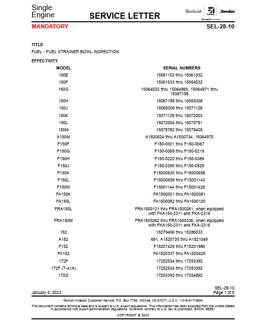
TITLE FUEL - FUEL STRAINER BOWL INSPECTION
EFFECTIVITY MODEL 150E 150F 150G
150H 150J 150K 150L 150M A150M F150F F150G F150H F150J F150K F150L F150M FA150K FA150L FRA150L
F17200754 F17200755 thru F17200804 F17200805 thru F17201034 F17201035 thru F17201514 F17201515 thru F17202039 F17202040 thru F17202254 680, R1722000 thru R1723454 FR17200591 thru FR17200675 17700001, 17700003 thru 17701164
FRA150M
152 A152 F152 FA152 172F 172F (T-41A) 172G
SERIAL NUMBERS 15061153 thru 15061532 15061533 thru 15064532 15064533 thru 15064969, 15064971 thru
max3485中文资料
MAX3483, MAX3485, MAX3486, MAX3488, MAX3490以及MAX3491是用于RS-485与RS-422通信的3.3V,低功耗收发器,每个器件中都具有一个驱动器和一个接收器。
MAX3483和MAX3488具有限摆率驱动器,可以减小EMI,并降低由不恰当的终端匹配电缆引起的反射,实现最高250kbps的无差错数据传输。
MAX3486的驱动器摆率部分受限,可以实现最高2.5Mbps的传输速率。
MAX3485,MAX3490和MAX3491则可以实现最高10Mbps 的传输速率。
驱动器具有短路电流限制,并可以通过热关断电路将驱动器输出置为高阻状态,防止过度的功率损耗。
接收器输入具有失效保护特性,当输入开路时,可以确保逻辑高电平输出。
使用MAX3488, MAX3490和MAX3491可以实现全双工通信,而MAX3483,MAX3485与MAX3486则为半双工应用设计。
这篇文章介绍的就是MAX34852 芯片介绍2.1 主要特点半双工速率:10Mbps限摆率:NO接收允许控制:YES 关断电流:2 nA引脚数:82.2 引脚配置根据上图、上表可知:DE和RO为使能管脚。
DE为低电平、RE为低电平时为接收;DE 为高电平、RE为高电平时为发送;RO和DI为数据管脚。
RO为接收,DI为发送;因此我们经常将DE和RE直接连接,用一个IO口控制(见3.2 电路实现)。
3.1 应用场景工业控制局域网集成服务数字网络低功耗RS-485/RS-422收发器(我做的几个项目都是该功能)分组交换技术电信用于EMI敏感应用的收发器3.2 电路实现485是2线式,两个485接口的设备相连通过A、B两根线即可(也就是至少2个485芯片),连接方式如下图所示:我们使用MAX3485一般是用下图电路:从上图中我们可以看到:RO直接和TTL电平的UART_RX(或模拟串口的RX)相连,DI直接和TTL电平的UART_TX(或模拟串口的TX)相连,R34为1K。
RT314024中文资料

018 = 18VDC 048 = 48VDC 024 = 24VDC
4
012
Stock Items
RT114012 RT114024 RT134012
RT134024 RTB14005 RTB14012
RTB14024 RTB34012 RTB34024
RT314012 RT314024 RT334012
90
4.2
66.7
009
202
6.3
44.4
012
360
8.4
33.3
018
810
12.6
22.2
024
1,440
16.8
16.7
048
5,760
33.6
8.3
Applied Coil Voltage (% of rated nom.)
Max. Ambient Temp. vs. Coil Voltage
B300, 360VA @ 240VAC*
TV-3 @120VAC*
Type Resistive/GP
Resistive Resistive/GP
Resistive Motor Motor Motor Motor
Tungsten Pilot Duty
Resistive/GP Resistive/GP
300
260
220
180
0A
8A
140
12A 16A
100 60
0
B
A
20
40
60
80
100
Max. Allowable Ambient Temp. (°C)
A: Coil temperature = Ambient temperature. B: 110% of nominal coil voltage at rated contact load.
AO4459中文资料

AO4459中⽂资料SymbolTyp Max 33406275R θJL 1824Maximum Junction-to-Lead CSteady-State°C/WThermal Characteristics ParameterUnits Maximum Junction-to-AmbientAt ≤ 10s R θJA °C/W Maximum Junction-to-Ambient ASteady-State °C/W AO4459AO4459SymbolMin TypMaxUnits BV DSS -30V -1T J =55°C-5I GSS ±100nA V GS(th)-1.5-1.85-2.5V I D(ON)-30A 3846T J =125°C53685872m ?g FS 11S V SD -0.78-1V I S-3.5A C iss 668830pF C oss 126pF C rss 92pF R g69?Q g (10V)12.716nC Q g (4.5V) 6.4nC Q gs 2nC Q gd 4nC t D(on)7.7ns t r 6.8ns t D(off)20ns t f 10ns t rr 2230ns Q rr15nCTHIS PRODUCT HAS BEEN DESIGNED AND QUALIFIED FOR THE CONSUMER MARKET. APPLICATIONS OR USES AS CRITICAL COMPONENTS IN LIFE SUPPORT DEVICES OR SYSTEMS ARE NOT AUTHORIZED. AOS DOES NOT ASSUME ANY LIABILITY ARISING OUT OF SUCH APPLICATIONS OR USES OF ITS PRODUCTS. AOS RESERVES THE RIGHT TO IMPROVE PRODUCT DESIGN,FUNCTIONS AND RELIABILITY WITHOUT NOTICE.DYNAMIC PARAMETERS Maximum Body-Diode Continuous CurrentGate resistanceV GS =0V, V DS =0V, f=1MHzV GS =0V, V DS =-15V, f=1MHz Input Capacitance Output Capacitance Turn-On Rise Time Turn-Off DelayTime V GS =-10V, V DS =-15V, R L =2.5?, R GEN =3?Turn-Off Fall TimeTurn-On DelayTime SWITCHING PARAMETERSTotal Gate Charge (4.5V)Gate Source Charge Gate Drain Charge Total Gate Charge (10V)V GS =-10V, V DS =-15V, I D =-6.5Am ?V GS =-4.5V, I D =-5AI S =-1A,V GS =0V V DS =-5V, I D =-6.5AR DS(ON)Static Drain-Source On-ResistanceForward TransconductanceDiode Forward VoltageI DSS µA Gate Threshold Voltage V DS =V GS I D =-250µA V DS =-24V, V GS =0VV DS =0V, V GS =±20V Zero Gate Voltage Drain Current Gate-Body leakage current Electrical Characteristics (T J =25°C unless otherwise noted)STATIC PARAMETERS ParameterConditions Body Diode Reverse Recovery Time Body Diode Reverse Recovery ChargeI F =-6.5A, dI/dt=100A/µsDrain-Source Breakdown Voltage On state drain currentI D =-250µA, V GS =0V V GS =-10V, V DS =-5V V GS =-10V, I D =-6.5AReverse Transfer Capacitance I F =-6.5A, dI/dt=100A/µs A: The value of R θJA is measured with the device mounted on 1in 2FR-4 board with 2oz. Copper, in a still air environment with T A =25°C. The value in any a given application depends on the user's specific board design. The current rating is based on the t ≤ 10s thermal resistance rating.B: Repetitive rating, pulse width limited by junction temperature.C. The R θJA is the sum of the thermal impedence from junction to lead R θJL and lead to ambient.D. The static characteristics in Figures 1 to 6 are obtained using < 300µs pulses, duty cycle 0.5% max.E. These tests are performed with the device mounted on 1 in 2FR-4 board with 2oz. Copper, in a still air environment with T A =25°C. The SOA curve provides a single pulse rating. Rev0 Sept 2006AO4459AO4459。
XP143 Specification-Chinese

φ0 .7 φ1 .0 φ1 .3 φ1 .8 φ2 .5 φ3 .7
φ5 .0
对应于吸嘴尺寸φ0.37~φ2.5mm 3) 吸嘴配置的限制
对应于吸嘴尺寸φ3.7~φ5.0mm
吸嘴 N o .4
吸嘴 N o .1 吸嘴 N o .10
吸嘴 N o .7
对于中型对应吸嘴φ3.7,φ5.0,安装位置 有限制。 (安装位置:吸嘴No.1,4,7,10)
5. 选 项
5.1 选项 ____________________________________________ 13
6. 机器外观
6.1 外观图 __________________________________________ 14 Spec1(前后MFU-X10E类型) ___________________________ 14
学习MSA影像处理后可以以强有力的图形匹配对所有的特殊元件方便地进行 影像处理
查找线
<创建模板例>
MSA的影像处理程序不是直接参考物理像素,而是根据虚拟影像画面,可以 在任意的位置、角度进行影像处理以达到高解析度以及高精度。
-2-
XP143-020505RS
1. 概 要
1.2.3 高生产率
1) 由于采用了独特的“ON-THE-VISION”系统和旋转工作头,实现了以周期时 间0.165秒进行贴装。此外,不像原来的多吸嘴机型那样要以同时吸取作为 前提条件,减少了因电路板的种类和元件种类的不同而产生的运转率的变 动。可以保持高的生产量。
1.2.6 与需求相对应的规格选择
在供料平台上,可以选择可以脱卸的MFU-X10E类型或者固定类型。更进一 步,可以选择Side1,Side2的双供料平台的规格,或者是仅仅Side1的单供 料平台的规格。可以从以下6种类型中选择类型。
DLW5BTN142SQ2L;DLW5BTN102SQ2L;DLW5BTN101SQ2L;DLW5BTN251SQ2L;DLW5BTN501SQ2L;中文规格书,Datasheet资料
Operating
(at 100MHz/20°C)
Temperature Range
DLW5BTN101SQ2p DLW5BTN251SQ2p DLW5BTN501SQ2p DLW5BTN102SQ2p DLW5BTN142SQ2p Number of Circuit: 1
100ohm (Typ.) 250ohm (Typ.) 500ohm (Typ.) 1000ohm (Typ.) 1400ohm (Typ.)
Noise Suppression Products/EMI Suppression Filters > Common Mode Choke Coil > Wire Wound Type for Large Current
Data Sheet
1
Common Mode Choke Coil Wire Wound Type for Large Current
2012.3.1
/
/
Noise Suppression Products/EMI Suppression Filters > Common Mode Choke Coil > Wire Wound Type for Large Current
0.5 min. (L) 5.0±0.3
0.45 min. (T) 2.35±0.15
1.3±0.3
1.7±0.3
(4) (3) 1.3±0.3 0.9±0.3
: Electrode (in mm)
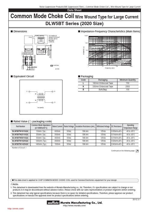
c Impedance-Frequency Characteristics (Main Items)
10000 Common mode
Notice Solderability of Tin plating termination chip might be deteriorated when low temperature soldering profile where peak solder temperature is below the Tin melting point is used. Please confirm the solderability of Tin plating termination chip before use.
RTX系列低阻值金属膜晶片电阻器规格标准书

4 尺寸:
Unit:mm Dimension L Type RTX05 Size Code 0805 2.00±0.10 3.05±0.10 6.30±0.20 1.25±0.10 1.55±0.10 3.20±0.20 0.55±0.10 0.35±0.20 0.35±0.20 0.55±0.10 0.50±0.20 0.50±0.20 0.55±0.10 0.65±0.20 0.65±0.20 W H L1 L2
70
155
20 0 -55 20 40 60 80 100 120 140 160 環境溫度(℃)
3.2 額定電流:
額定電流:對於額定功率之直流或交流(商用週率有效值rms)電流。 可用下列公式求得,但求得之值若超過規格表內之最高電流時,則以最高額定電流為其額定電 流。 I=額定電流(A) P=額定功率(W) R=公稱阻值(Ω)
RTX25 (2512)
阻值範圍 D(±0.5%) 50mΩ ≦R< 100mΩ 100mΩ ≦R< 1000mΩ 50mΩ ≦R< 100mΩ 100mΩ ≦R< 1000mΩ 50mΩ ≦R< 100mΩ 100mΩ ≦R< 1000mΩ
------
F(±1%)、G(±2%)、J(±5%) 50mΩ ≦R< 100mΩ 100mΩ ≦R< 1000mΩ 50mΩ ≦R< 100mΩ 100mΩ ≦R< 1000mΩ 50mΩ ≦R< 100mΩ 100mΩ ≦R< 1000mΩ 45mΩ ≦R< 50mΩ 50mΩ ≦R< 100mΩ 100mΩ ≦R≦ 1000mΩ 45mΩ ≦R< 50mΩ 50mΩ ≦R< 100mΩ 100mΩ ≦R≦ 1000mΩ 45mΩ ≦R< 50mΩ 50mΩ ≦R< 100mΩ 100mΩ ≦R≦ 1000mΩ 100mΩ ≦R< 1000mΩ 100mΩ ≦R< 1000mΩ
德力西电气Rt14

技术参数
额定电压:380V AC 额定电流:2~63A 额定分断能力:100kA 功率因数:0.1~0.2 变截面熔体为纯铜带(丝)制成,灭弧介质为石英砂 熔体两端采用点焊与端帽牢固电连接 符合标准:IEC60269/GB13539 符合认证:CCC认证
订货信息
产品名称 熔断体 熔断器 电流(A) 20 外形尺 寸(mm) 10×38 分断能 力(kA) 100 额定耗散 功率(W) ≤3 熔断体 电流(A) 2 4 6 8 10 12 16 20 32 14×51 100 ≤5 2 4 6 8 10 12 16 20 25 32 63 22×58 100 ≤9.5 16 20 25 32 40 50 63 产品名称 底座 底座电流 (A) 20 32 63 熔断体外形尺寸 (mm) 10×38 14×51 22×58 RT1420Z RT1432Z RT1463Z 订货号 RT1418M1038T2 RT1418M1038T4 RT1418M1038T6 RT1418M1038T8 RT1418M1038T10 RT1418M1038T12 RT1418M1038T16 RT1418M1038T20 RT1418M1451T2 RT1418M1451T4 RT1418M1451T6 RT1418M1451T8 RT141819M1451T10 RT141819M1451T12 RT141819M1451T16 RT141819M1451T20 RT141819M1451T25 RT141819M1451T32 RT14M2258T16 RT14M2258T20 RT1419M2258T25 RT1419M2258T32 RT1419M2258T40 RT1419M2258T50 RT1419M2258T63 订货号
迪瑞芬豪系列固定卫星通信电话说明书

TranSATRST620The Beam TranSAT Fixed Satellite Telephone provides acomplete hands-free voice and telephone for a wide range ofmobile and fixed site applications where easy access to reliablevoice and data communications is required.The terminal provides a compact fully functioned user handsetand supports both hands-free and privacy modes of operation,automatically switching between either mode with the handsetin or out of the cradle.The system can also be used as a permanent non hands-freesolution simply by not connecting the microphone. The loudring indication through the speaker system makes it an idealinstallation in a noisy environment.The RST620 is equipped with an RS232 serial data port toaccess Iridium data servicesEmergencyVehiclesHeavy TrucksCruise ShipsSmall Aircrafts Handsfree / Privacy ModeVoice/Data/Internet/FAX/SMSCommunication System InegrationEcho Cancellation / Full duplexLatest echo cancellation technology is deployed onTranSAT to enhance handsfree voice quality.Enhanced FeaturesSupport featuressuch as horn alert, radiomute,data connectivity and allow the use of a compactintelligent user handset in privacy mode.11-32V DC Power InputThe DC power input and terminal is capable ofbeing wired to an auxiliary/accessory power supplyas well as constant power.Auxiliary & constant powerThe unit is equipped with intelligent power offfeatures. Whereby the unit will turn off afterminutes when ignition is off. The unit also hasthe option of powering up on accessory power inemergency applications.Voice/Data/Internet/SMS/FaxThe complete range of Iridium data services allowsyou to simply and conveniently gain access toInternet, Email, and corporate LAN.The terminal also supports SMS and the followingIridium Data Services;• Circuit Switched Data• Direct Internet• RUDICS• Short Burst DataPrivate or Handsfree modeHands-free operation allows for quality integrationinto a vehicle/vessel/aircraft with easy access tomaking and receiving calls in a hands-free mode, italso allows the use for privacy mode.Compact Intelligent HandsetThe compact Intelligent Handset provides easyaccess to make and receive calls, access phonebook and SMS as well as switching betweenhandsfree and privacy mode.HandsfreeVoice Data Horn AlertHFISide2RED = +BATT (11 to 32 VDC)BLACK = -BATT (GND)GREEN = ACC PWRHFISide1MicrophoneAntenna1A FusePositive 3A Fuse GroundPOWER SPECIFICATIONSPower input voltage11 - 32 V DC Power Consumption ( AMPS )12 V DC 24 V DC Stand-by - inc handset0.330.14Transmit - inc handset 0.630.23ENVIRONMENT SPECIFICATIONS Temperature Degrees °C Degrees °FOperating Range -15 to +55+5 to +131Storage -30 to +85-22 to +185Humidity 85% non condensing CONNECTORS/INTERFACES Transceiver D25Intelligent Handset RJ45 DPL BUS Data Port RS232 Serial Interface Speaker 3.5mm mono Microphone 2.5mm mono Constant power Screw Connector Auxiliary power Screw Connector Horn Alert Screw Connector Audio MuteScrew ConnectorPHYSICAL SPECIFICATIONS LBT Interface Dimensions - mm 162.4 x 81.6x8183 x 130 x 27Dimensions - inches 38 x 3.16 x 1.17.2 x 5.1 x 1.0Weight - kg 4200.3Weight - lbs9260.66CERTIFICATIONSIEC60945Eelectrical Safety EMC ComplianceHFI - AS/NZ 4601: 1999 - 3.3.4 & 3.3.5Temperature/Humidity/Impact Vibration / Accelerated Aging Independent Aeronautical certification MUST be gained prior to installation.KIT CONTENTSIridium 9522B Transceiver module Main terminal Iridum Intelligent HandsetHandsfree and power InterfaceCable assemblies: DC cables, interface cables Mounting adhesive / velcroData cableUser & Installation manual RST710RST714RST715RST720RST932RST933RST972S RST972RST949Mast Mount Antenna WHIP Antenna (incl 5m cable)Magnetic Mount Antenna (incl 5m cable)Bolt Mount Antenna (incl 5m cable)6m / 19’ Iridium Antenna Cable 12m / 36’ Iridium Antenna Cable 15m extension cable for Intelligent Handset 30m extension cable for Intelligent Handset DPL Aplification cable to increase the headset volume for noisy environments。
欧洲品牌电磁组件型号X12345产品说明书
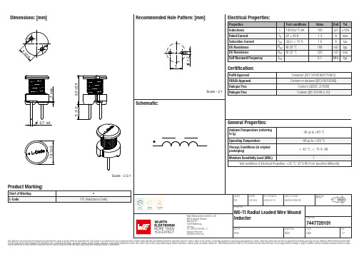
Dimensions: [mm]Scale - 2,5:17447720101A74477201017447720101T e m p e r a t u r eT T T 7447720101Cautions and Warnings:The following conditions apply to all goods within the product series of WE-TI of Würth Elektronik eiSos GmbH & Co. KG:General:•This electronic component was designed and manufactured for use in general electronic equipment.•Würth Elektronik must be asked for written approval (following the PPAP procedure) before incorporating the components into any equipment in fields such as military, aerospace, aviation, nuclear control, submarine, transportation (automotive control, train control, ship control), transportation signal, disaster prevention, medical, public information network, etc. where higher safety and reliability are especially required and/or if there is the possibility of direct damage or human injury.•Electronic components that will be used in safety-critical or high-reliability applications, should be pre-evaluated by the customer. •The component is designed and manufactured to be used within the datasheet specified values. If the usage and operation conditions specified in the datasheet are not met, the wire insulation may be damaged or dissolved.•Do not drop or impact the components, the component may be damaged.•Würth Elektronik products are qualified according to international standards, which are listed in each product reliability report. Würth Elektronik does not warrant any customer qualified product characteristics beyond Würth Elektroniks’ specifications, for its validity and sustainability over time.•The customer is responsible for the functionality of their own products. All technical specifications for standard products also apply to customer specific products.Product specific:Soldering:•The solder profile must comply with the technical product specifications. All other profiles will void the warranty.•All other soldering methods are at the customers’ own risk.Cleaning and Washing:•Washing agents used during the production to clean the customer application might damage or change the characteristics of the wire insulation, marking or plating. Washing agents may have a negative effect on the long-term functionality of the product. Potting:•If the product is potted in the costumer application, the potting material might shrink or expand during and after hardening. Shrinking could lead to an incomplete seal, allowing contaminants into the core. Expansion could damage the components. We recommend a manual inspection after potting to avoid these effects. Storage Conditions:• A storage of Würth Elektronik products for longer than 12 months is not recommended. Within other effects, the terminals may suffer degradation, resulting in bad solderability. Therefore, all products shall be used within the period of 12 months based on the day of shipment.•Do not expose the components to direct sunlight.•The storage conditions in the original packaging are defined according to DIN EN 61760-2.•The storage conditions stated in the original packaging apply to the storage time and not to the transportation time of the components. Packaging:•The packaging specifications apply only to purchase orders comprising whole packaging units. If the ordered quantity exceeds or is lower than the specified packaging unit, packaging in accordance with the packaging specifications cannot be ensured. Handling:•Violation of the technical product specifications such as exceeding the nominal rated current will void the warranty.•Applying currents with audio-frequency signals might result in audible noise due to the magnetostrictive material properties. •Due to heavy weight of the components, strong forces and high accelerations might have the effect to damage the electrical connection or to harm the circuit board and will void the warranty.•Please be aware that products provided in bulk packaging may get bent and might lead to derivations from the mechanical manufacturing tolerances mentioned in our datasheet, which is not considered to be a material defect.•The temperature rise of the component must be taken into consideration. The operating temperature is comprised of ambient temperature and temperature rise of the component.The operating temperature of the component shall not exceed the maximum temperature specified.These cautions and warnings comply with the state of the scientific and technical knowledge and are believed to be accurate and reliable.However, no responsibility is assumed for inaccuracies or incompleteness.Würth Elektronik eiSos GmbH & Co. KGEMC & Inductive SolutionsMax-Eyth-Str. 174638 WaldenburgGermanyCHECKED REVISION DATE (YYYY-MM-DD)GENERAL TOLERANCE PROJECTIONMETHODTRi001.0012019-07-17DIN ISO 2768-1mDESCRIPTIONWE-TI Radial Leaded Wire WoundInductor ORDER CODE7447720101SIZE/TYPE BUSINESS UNIT STATUS PAGEImportant NotesThe following conditions apply to all goods within the product range of Würth Elektronik eiSos GmbH & Co. KG:1. General Customer ResponsibilitySome goods within the product range of Würth Elektronik eiSos GmbH & Co. KG contain statements regarding general suitability for certain application areas. These statements about suitability are based on our knowledge and experience of typical requirements concerning the areas, serve as general guidance and cannot be estimated as binding statements about the suitability for a customer application. The responsibility for the applicability and use in a particular customer design is always solely within the authority of the customer. Due to this fact it is up to the customer to evaluate, where appropriate to investigate and decide whether the device with the specific product characteristics described in the product specification is valid and suitable for the respective customer application or not.2. Customer Responsibility related to Specific, in particular Safety-Relevant ApplicationsIt has to be clearly pointed out that the possibility of a malfunction of electronic components or failure before the end of the usual lifetime cannot be completely eliminated in the current state of the art, even if the products are operated within the range of the specifications.In certain customer applications requiring a very high level of safety and especially in customer applications in which the malfunction or failure of an electronic component could endanger human life or health it must be ensured by most advanced technological aid of suitable design of the customer application that no injury or damage is caused to third parties in the event of malfunction or failure of an electronic component. Therefore, customer is cautioned to verify that data sheets are current before placing orders. The current data sheets can be downloaded at .3. Best Care and AttentionAny product-specific notes, cautions and warnings must be strictly observed. Any disregard will result in the loss of warranty.4. Customer Support for Product SpecificationsSome products within the product range may contain substances which are subject to restrictions in certain jurisdictions in order to serve specific technical requirements. Necessary information is available on request. In this case the field sales engineer or the internal sales person in charge should be contacted who will be happy to support in this matter.5. Product R&DDue to constant product improvement product specifications may change from time to time. As a standard reporting procedure of the Product Change Notification (PCN) according to the JEDEC-Standard inform about minor and major changes. In case of further queries regarding the PCN, the field sales engineer or the internal sales person in charge should be contacted. The basic responsibility of the customer as per Section 1 and 2 remains unaffected.6. Product Life CycleDue to technical progress and economical evaluation we also reserve the right to discontinue production and delivery of products. As a standard reporting procedure of the Product Termination Notification (PTN) according to the JEDEC-Standard we will inform at an early stage about inevitable product discontinuance. According to this we cannot guarantee that all products within our product range will always be available. Therefore it needs to be verified with the field sales engineer or the internal sales person in charge about the current product availability expectancy before or when the product for application design-in disposal is considered. The approach named above does not apply in the case of individual agreements deviating from the foregoing for customer-specific products.7. Property RightsAll the rights for contractual products produced by Würth Elektronik eiSos GmbH & Co. KG on the basis of ideas, development contracts as well as models or templates that are subject to copyright, patent or commercial protection supplied to the customer will remain with Würth Elektronik eiSos GmbH & Co. KG. Würth Elektronik eiSos GmbH & Co. KG does not warrant or represent that any license, either expressed or implied, is granted under any patent right, copyright, mask work right, or other intellectual property right relating to any combination, application, or process in which Würth Elektronik eiSos GmbH & Co. KG components or services are used.8. General Terms and ConditionsUnless otherwise agreed in individual contracts, all orders are subject to the current version of the “General Terms and Conditions of Würth Elektronik eiSos Group”, last version available at .Würth Elektronik eiSos GmbH & Co. KGEMC & Inductive SolutionsMax-Eyth-Str. 174638 WaldenburgGermanyCHECKED REVISION DATE (YYYY-MM-DD)GENERAL TOLERANCE PROJECTIONMETHODTRi001.0012019-07-17DIN ISO 2768-1mDESCRIPTIONWE-TI Radial Leaded Wire WoundInductor ORDER CODE7447720101SIZE/TYPE BUSINESS UNIT STATUS PAGE。
VK3214

VK3214UART总线接口四通道通用异步收发器无铅封装1.产品概述VK3214是UART TM接口的4通道UART器件。
VK3214实现UART桥接/扩展4个串口(UART)的功能。
扩展的子通道的UART具备如下功能特点:每个子通道UART的波特率、字长、校验格式可以独立设置,最高可以提供1Mbps的通信速率。
可选择的奇校验,偶校验和无校验模式UART主接口可以通过引脚设置为红外模式UART主接口可以通过引脚选择是否采用转义字符模式3.应用领域车载信息平台/车载GPS定位系统远传自动抄表(AMR)系统POS/税控POS/金融机具IRQ 10 O 中断输出信号,低电平有效,建议外接上拉电阻,典型值5.1K OSCO 19 I 晶振输入; OSCI 20O晶振输出;VCC 9,18 - 电源 2.5V ~5.5V 工作范围 GND1,13 -地7.寄存器描述C1,C0:子通道号,00~11分别对应子串口1到子串口4。
7.2 寄存器描述7.2.1 GCR 全局控制寄存器:(0001)位 复位值 功能描述类型Bit7GBDEN 全局广播使能位 0:禁止数据广播 1:使能数据广播W/RR Bit1 0 U2IF子串口2中断标志位0:子串口2无中断1:子串口2有中断R Bit0 0 U1IF 子串口1中断标志位0:子串口1无中断1:子串口1有中断7.2.6 SFOCR 子串口FIFO控制寄存器:(1001)7.2.8 SIFR 子串口中断标志寄存器:(1100)7.2.10 SFSR 子串口FIFO状态寄存器:(1110)位复位值功能描述类型Bit7 – 4 0000 TCNT3—0 子串口发送FIFO中的数据个数RBit3 -- 0 0000 RCNT3—0子串口接收FIFO中的数据个数R7.2.11 SFDR 子串口FIFO数据寄存器:(1111)位复位值功能描述类型R/W Bit7 – 0 xxxxxxxx 写操作时:写入的子串口发送FIFO的数据读操作时:读出的子串口接收FIFO的数据图8.3 VK3214中断结构图VK3214的每个子串口都有独立的中断系统,包括:FIFO数据错误中断,发送FIFO触发点中断,接收FIFO 触发点中断。
泰尔富G型说明书

2.2.3 主回路端子的接线..................................................................................................... 20
5 TECH.FULL
目录
2.2.4 控制回路端子的接线................................................................................................ 23
1.2.4 产品型号说明 ........................................................................................................ 11
1.3 产品外观............................................................................................................................ 12
1.4 变频器标准规格 ................................................................................................................ 12
MSP430F149中文资料部分

基于MSP430F149的GPS
(芯片篇)
1、系统功能框图
2芯片资料:
MSP430F149:
低电源电压范围:1.8~3.6V
超低功耗:待机模式:1.6uA 关闭模式(RAM保持):0.1uA 活动模式:280uA at 1MHz,2.2V
5种省电模式
6us内从待机模式唤醒
16位RISC结构,125ns指令周期
带内部参考,采样保持和自动扫描特性的12位A/D转换器
有7个捕获/比较寄存器的16位定时器Timer_B 有3个捕获/比较寄存器的16位定时器Timer_A
片内集成比较器
串行在线编程,无需外部编程电压,安全熔丝可编程代码保护.
器件系列包括:–MSP430F133:8KB+256B闪速存储器,256B的RAM –MSP430F135:16KB+256B闪速存储器,512B的RAM –MSP430F147,MSP430F1471:32KB+256B闪速存储器,1KB的RAM –MSP430F148, MSP430F1481:48KB+256B闪速存储器,2KB的RAM –MSP430F149, MSP430F1491:60KB+256B闪速存储器,2KB的RAM
可用封装:64脚方形扁平封装(QFP).
功能框图。
- 1、下载文档前请自行甄别文档内容的完整性,平台不提供额外的编辑、内容补充、找答案等附加服务。
- 2、"仅部分预览"的文档,不可在线预览部分如存在完整性等问题,可反馈申请退款(可完整预览的文档不适用该条件!)。
- 3、如文档侵犯您的权益,请联系客服反馈,我们会尽快为您处理(人工客服工作时间:9:00-18:30)。
1
Datasheet Rev. FE1 Issued 2006/05 Dimensions are in mm unless otherwise specified and are shown for reference purposes only. Product specification according to IEC 61810-1. Product data, technical parameters, test conditions and processing information only to be used together with the 'Definitions' at in the ‘Schrack’ section. Specifications subject to change.
General Purpose Relays
Power PCB Relay RT1 bistable (Continued)
Product key Type Version 3 16 A, pinning 5 mm, flux proof Contact configuration 1 1 CO contact Contact material 4 AgNi 90/10 Coil Coil code: please refer to coil versions table, preferred types in bold print
Coil 12 VDC 24 VDC 12 VDC 24 VDC
Part number 8-1393239-0 8-1393239-1 8-1393239-7 8-1393239-8
3
Datasheet Rev. FE1 Issued 2006/05 Dimensions are in mm unless otherwise specified and are shown for reference purposes only. Product specification according to IEC 61810-1. Product data, technical parameters, test conditions and processing information only to be used together with the 'Definitions' at in the ‘Schrack’ section. Specifications subject to change.
General Purpose Relays
Power PCB Relay RT1 bistable
I I I I I
1 pole 16 A, 1 CO contact Polarized bistable version with 1 or 2 coils 5 kV / 10 mm coil-contact Reinforced insulation RoHS compliant (Directive 2002 / 95 / EC) as per product date code 0413
1 coil A1 A2 + +
A1 -
2 coils A3 + +
A2 -
Insulation
Dielectric strength coil-contact circuit open contact circuit Clearance / creepage coil-contact circuit Material group of insulation parts Tracking index of relay base Insulation to IEC 60664-1 Type of insulation coil-contact circuit open contact circuit Rated insulation voltage Pollution degree Rated voltage system Overvoltage category 5000 Vrms 1000 Vrms W 10 / 10 mm W IIIa PTI 250 V reinforced functional 250 V 3 240 V III 2 400 V
ratings Load 20 A, 250 VAC, NO contact, 85°C, UL508 Pilot duty A300 (NO contact), B300 (CO/NC contact), UL508 1hp @ 240 VAC, 1/2hp @ 120 VAC, NO contact, UL508
Coil data
Rated coil voltage range DC coil Coil power Operative range Limiting voltage, % of rated coil voltage Minimum energization duration Maximum energization duration Coil insulation system according UL1446
Contact data
Contact configuration Contact set Type of interruption Rated current Rated voltage / max.switching voltage AC Limiting continuous current Maximum breaking capacity AC Limiting making capacity, max 4 s, duty factor 10% Contact material Mechanical endurance Rated frequency of operation with / without load Contact Type RT314 RT314 RT314 1 CO contatct single contact micro disconnection 16 A 240/400 VAC 20 A 4000 VA 30 A AgNi 90/10 > 5 x 10⁶ cycles 6 / 1200 min-1 Cycles 6x10³
1 coil
2 coils
5...24 VDC typ 400 mW typ 600 mW 2 120% 150% 30 ms 1 min at < 10% DF class F
Coil versions, bistable coil Coil Rated Operate Reset Coil Rated coil code voltage voltage voltage resistance power VDC VDC VDC c mW bistable, 1 coil A05 5 3.5 3.5 62+10% 403 A06 6 4.2 4.2 90+10% 400 + A12 12 8.4 8.4 360+10% 400 + A24 24 16.8 16.8 1440+10% 400 bistable, 2 coils F05 5 3.5 3.5 42+10% 595 F06 6 4.2 4.2 55+10% 655 + F12 12 8.4 8.4 240+10% 600 + F24 24 16.8 16.8 886+10% 650 All figures are given for coil without preenergization, at ambient temperature +23°C Other coil voltages on request
Other data
RoHS - Directive 2002/95/EC compliant as per product date code 0413 Flammability class according to UL94 V-0 Ambient temperature range 1 coil -10...+85°C 2 coils -40...+85°C Operate- / reset time typ 5 / 4 ms Bounce time NO / NC contact typ 1 / 3 ms Vibration / shock resistance (function) opening NC contact 3/5g opening closed NO contact 6 / 15 g Shock resistance (destruction) 100 g Category of protection RTII - flux proof Mounting pcb or on socket *) Mounting distance 0 mm Resistance to soldering heat flux-proof version 270 °C / 10 s Relay weight 14 g Packaging unit 1 coil 20 / 500 pcs 2 coils 100 pcs *) socket available for 1 coil version only, see Accessories
PCB layout / terminal assignment
Bottom view on solder pins
16 A, pinning 5 mm
Accessories
For 1 coil version, details see datasheet Accessories Power Relay RT
Applications Battery powered equipment or applications with "memory function”
