ABAQUS声学分析-acoustics-lecture6
Acoustic Analysis in Abaqus声学仿真
Webinar Title – Month Year – See View>Slide Master to change Improving Acoustic Performance
vibrating plate
fluid u
plate u
fluid u plate if r 0 : u fluid u plate if r 0 : u
Webinar Title – Month Year – See View>Slide Master to change Improving Acoustic Performance
Acoustic Analysis in Abaqus
2011 Feb web-training Simutech ution Corporation
Agenda
Acoustic Analysis in Abaqus
Structural Acoustic Applications Acoustic Problem Types Possible with Abaqus Acoustic 名詞解釋 Acoustic analysis的準備事項 Acoustic Analysis建模指引 Examples
Example of Volumetric Acceleration
A horizontal, flat rigid plate oscillating vertically imposes an acceleration on the acoustic fluid. An acoustic load is equal to this acceleration times the surface area of the plate. The load is the acceleration of a fluid particle if the volumetric drag (r) is zero.
Abaqus仿真分析培训课件

ABAQUS主要功能
复杂的固体力学结构力学系统,特别是能够驾驭非常 庞大复杂的问题和模拟高度非线性问题
模拟典型工程材料的性能,其中包括金属、橡胶、高 分子材料、复合材料、钢筋混凝土、可压缩超弹性泡 沫材料以及土壤和岩石等地质材料
(2)ABAQUS软件在求解非线性问题时具有非常明显的 优势。其非线性涵盖材料非线性、几何非线性和状态 非线性等多个方面。
综合性能对比
综合性能对比 1. ANSYS软件的命令流操作非常方便,对于结构循环优化方 面比较有优势,但目前还只是局限于线性方面,非线性方面 功能较差、近几年有一定发展; 2. ABAQUS软件则在显式非线性方面有些特色,但隐式非线 性方面比不上ADINA,且不具备流体的功能 3. ADINA软件则在结构非线性及多物理场耦合方面非常出色, 是全球非线性功能最强大的有限元软件之一,而且具有全球 最好的流固耦合分析功能。
二维热传导
D yA
C
1.0
E
0.5
0.2
Conductivity = 52W/m/oC Film coefficient = 750W/m2/oC Boundary conditions: = 100oC C along AB Heat flux = 0 along DA Convection to ambient temperature of 0oC along BC and CD Objective: Find q at E Target solution: 18.3oC at E
计 软件除具有上述常规和特殊的分析功能外,在材料模型,单元,载荷、
约束及连接等方面也功能强大并各具特点: 材料模型:定义了多种材料本构关系及失效准则模型,包括:弹性:线
Abaqus 声学分析

rep P P L lg 20=0c w SW I ==0lg 10I I L p =0lg 10W W L w =Abaqus 声学分析Airmage1. 要点1)基本物理量 2)实例模型说明 3)材料属性设定 4)求解类型设定 5)边界条件设定 6)载荷和声源 7)网格划分 8)结果后处理2. 基本物理量1) 声压设气体的初始压强为P 0,受到声扰动后,压强为P 0+P 。
则这个压强改变量就称为声压,单位为Pa ,一般取其有效值。
2) 声压级声压级(Sound Pressure Level )定义为声压得有效值与基准声压的有效值之比的常用对数20倍,(取分贝单位),即 式中,Pe 是测量声压,Pr 是参考声压,Pr 通常取2×10⁻⁵ Pa ,它是人耳对1kHz 空气声所能感觉到的最低声音的声压。
3) 声强声强(Sound Intensity )是指在垂直于传播方向上单位面积上通过的平均声能量流,即 4) 声强级声强级(Sound Intensity Level )定义为声强和参考声强之比的常用对数的10倍,即式中,基准声强I 0取10-12 W/m 2为可听最小声强。
5) 声功率级声功率级(Sound Power Level )定义为声功率与基准声功率之比的常用对数的10倍,即 式中,基准声功率W 0取10-12 W 。
3. 实例模型说明我们用下面的模型来说明分析流程4. 材料属性设定Abaqus 中模拟声音传播的材料需要的物性参数为两个,Density 和Acoustic Medium ,分别输入密度和体积模量(因为声波是纵波),如下图:这里输入了空气的材料性能。
在Abaqus 中声速公式统一用ρυ/k =来计算,这本就是液体的声速公式。
密度没什么问题,关键是体积模量k 。
对于气体中的声速ρυ/rP =,就有rP k =,P 是压强,r 为绝热系数,如该气体可认为是理想气体,则其绝热系数r 就是定压比热容与定容比热容之比,即v p C C r /=;固体中声速的计算公式为)21)(1()1(σσρσυ-+-=E L ,于是就有)21)(1()1(σσσ-+-=E k ,σ是泊松比。
ABAQUS基础和实例分析

2.1 ABAQUS/CAE的组成(Components)
❖ 主窗口的组成
工具栏(Toolbar) 环境栏(Context bar) 模型树(Model tree) 工具区(Toolbox area) 视图区(Viewport) 提示区(Prompt area) 信息区(Message area)
2.3 ABAQUS/CAE中的常用工具(Tools)
❖ 查询(Query) ❖ 数据点(Datum) ❖ 剖分(Partition) ❖ 集合(Set)与面(Surface) ❖ 显示组(Display Group)
实例1:路面结构的受力分析
❖ 主要目的:熟悉 ABAQUS/CAE中的常 用工具。
2.2 ABAQUS/CAE中的分析模块(Modules)
❖ 分析过程
❖ 分析模块
前处理 ABAQUS/CAE 或其它软件
输入文件: job.inp
模拟 ABAQUS/Standard 或 ABAQUS/Explicit
输出文件: job.odb,job.dat job.res,job.fil
后处理 ABAQUS/CAE 或其它软件
S4R,S3R,SAX1,SAX2, SAX2T
❖ 薄壳单元
STRI3, STRI35, STRI65,S4R5,S8R5,S9R5, SAXA
❖ 厚壳单元
S8R,S8RT
3.3.2壳单元自由度
conditions ) ❖ 分析类型( Analysis type ) ❖ 输出需求( Output requests )
4 ABAQUS中的常用命令
❖ 命令约定:
Abaqus选项内容讲解

总规则1、关键字必须以*号开头,且关键字前无空格2、**为注释行,它可以出现在文件中的任何地方3、当关键字后带有参数时,关键词后必须采用逗号隔开4、参数间都采用逗号隔开5、关键词可以采用简写的方式,只要程序能识别就可以了6、不需使用隔行符,如果参数比较多,一行放不下,可以另起一行,只要在上一行的末尾加逗号便可以*AMPLITUDE:定义幅值曲线amplitude这个选项允许任意的载荷、位移和其它指定变量的数值在一个分析步中随时间的变化(或者在ABAQUS/Standard分析中随着频率的变化)。
必需的参数:NAME:设置幅值曲线的名字可选参数:DEFINITION:设置definition=Tabular(默认)给出表格形式的幅值-时间(或幅值-频率)定义。
设置DEFINITION=EQUALL Y SPACED/PERIODIC/MODULATED/DECAY/SMOOTH STEP/SOLUTION DEPENDENT或BUBBLE来定义其他形式的幅值曲线。
INPUT:设置该参数等于替换输入文件名字。
TIME:设置TIME=STEP TIME(默认)则表示分析步时间或频率。
TIME=TOTAL TIME表示总时间。
V ALUE:设置V ALUE=RELATIVE(默认),定义相对幅值。
V ALUE=ABSOLUTE表示绝对幅值,此时,数据行中载荷选项内的值将被省略,而且当温度是指定给已定义了温度TEMPERA TURE=GRADIENTS(默认)梁上或壳单元上的节点,不能使用ABSOLUTE。
对于DEFINITION=TABULAR的可选参数:SMOOTH:设置该参数等于DEFINITION=TABULAR的数据行第一行1、时间或频率2、第一点的幅值(绝对或相对)3、时间或频率4、第二点的幅值(绝对或相对) 等等基本形式:*Amplitude,name=Amp-10.,0.,0.2,1.5,0.4,2.,1.,1.*BEAM SECTION:当需要数值积分时定义梁截面beamsection*BOND:定义绑定和绑定属性*BOUNDARY:定义边界条件用来在节点定义边界条件或在子模型分析中指定被驱动的节点。
abaqus中英文

abaqus中英文ABAQUS专业术语中英文对照前后处理器模块——ABAQUS/CAE几何体建模——GeometryGeometry Creation Tools(几何体生成工具)2-D Sketcher(二维草图)Sketch T ools and Options(草图工具和选项)Geometry Import/Export(几何体导入和导出)Geometry Repair T ools(几何体修补工具)Mesh Edit(网格编辑)模型装配——AssemblyInstance Tools(实例工具)Sets and Surfaces(集合和表面)Display Groups(显式组)Merge/Cut T ools(合并/剪切操作)定义材料性质——PropertiesMaterial Models(材料模型)General(一般性质)Elasticity(弹性性质)Electrical properties(电性质)Mass diffusion(质量扩散)Plasticity(塑性性质)Pore fluid properties(孔隙流体性质)Thermal properties(热性质)Gasket(垫片)Acoustic medium(声学介质)Equation of state (EOS) materials(状态方程)User materials(用户自定义材料)Hyperelastic material evaluation(超弹性材料评估)Sections(截面性质)Solid(实体)homogeneous(各向同性的), generalized plane strain(广义平面应变的Shell(壳)homogeneous(各向同性的), composite(复合材料壳单元), membrane (薄膜),surface (rebar layers)(带钢筋层的曲面)Beam(梁) beam(梁), truss(杆)Point(点)mass(质量单元), rotary inertia(转动惯量), damping(阻尼), capacitance(电容)Gasket(垫片)Beam section profiles(梁截面形状)Skin(蒙皮)Orientations(材料方向)分析流程功能——AnalysisGeneral, Linear and Nonlinear Analyses(通用,线性和非线性分析)Static stress/displacement analysis(静力分析)Viscoelastic/viscoplastic response(粘弹/粘塑响应)Dynamic stress/displacement analysis(动力分析)Heat transfer analysis(热传导分析)Mass diffusion analysis(质量扩散分析)Acoustic analysis(声学分析)Coupled problems(耦合问题)– Thermo-mechanical(热固)– Thermo-electrical(热电)– Piezoelectric(压电)– Pore fluid flow-mechanical(孔隙流动)– Thermo-mechanical mass diffusion(热-固-质量扩散)– Shock and acoustic-structural(冲击和声固耦合)Linear Perturbation Analyses(线性摄动分析)Static stress/displacement analysis(应力位移静力分析)– Linear static stress/displacement analysis(应力位移线性静力分析)– Eigenvalue buckling estimates(特征值屈曲分析)Dynamic stress/displacement analysis(应力位移动力学分析)– Natural frequency extraction(自振频率提取)– Complex eigenvalue extraction(复频率提取)– Transient response via modal superposition(通过模态叠加法计算瞬态响应)–Steady-state response to harmonic loading (简谐载荷下的稳态响应)– Response spectrum analysis(响应谱分析)– Random response analysis(随机响应分析)Analysis Controls(分析控制)Output Requests(输出请求)定义约束和接触——Constraints and InteractionsContact(接触)General contact (ABAQUS/Explicit)(通用接触)Surface-to-surface contact(面面接触)Self-contact(自接触)Contact Properties(接触性质)Constraints(约束)Thermal(热)Loads(载荷)Mechanical(机械)Bolt load(螺栓预紧力)Thermal(热)Acoustic(声场)Fluid(流体)Electrical(电)Mass diffusion(质量扩散)Fields(场)Multiple load cases(多工况)Connectors(连接单元)Boundary Conditions(边界条件)Nodal(节点位移)Velocity(速度)Acceleration(加速度)Velocity/angular velocity(角速度)Submodel(子模型)Pore pressure(孔压)Electric potential(电势)Temperatures(温度)网格划分——MeshingMesh Seeding(网格种子)Structured Meshing(结构化分网)Surface Meshing(表面分网)Solid Meshing(实体分网)Virtual Topology(虚拟拓扑)单元库——Element Library Beam(梁单元)Truss(杆单元)Connector(连接单元)Shell(壳单元)Membrane(薄膜单元)Continuum(实体单元)Elbow(弯管单元)Gasket(垫片单元)Pipe(管道单元)后处理——VisualizationModel plotting(模型图)Deformed, contour, vector/tensor, path, tickmark, overlay, material orient ations, X–Y plots(变形图,云图、矢量/张量图、材料方向图、X-Y曲线图等)Animations(动画)Stress linearization(应力线性化)Tabular data reports(数据报表)Probe/query tools(查询工具)Diagnostics visualization(结果诊断)过程自动化——Process AutomationPython scripting(Python脚本)GUI toolkit(用户界面工具包)Macro manager(宏管理器)隐式求解器模块——ABAQUS/STANDARD分析类型——Analysis TypesGeneral, Linear and Nonlinear Analyses(通用,线性和非线性分析) Static stress/displacement analysis(静力分析)Direct cyclic analysis(直接载荷循环分析)Viscoelastic/viscoplastic response(粘弹性和粘塑性)Dynamic stress/displacement analysis(动力学分析)Steady-state transport analysis(稳态传输分析)Heat transfer analysis(热传导分析)Mass diffusion analysis(质量扩散分析)Acoustic analysis(声场分析)Coupled analysis(耦合分析)Linear Perturbation Analyses(线性摄动分析)分析和建模技术——Analysis and Modeling Techniques求解技术——Solution Techniques材料定义——Material DefinitionsElastic Mechanical Properties(弹性机械性质)Inelastic Mechanical Properties(非弹性机械性质)Additional Material Properties(其他材料性质)单元库——Element LibraryContinuum(实体单元)Membranes(薄膜单元)Beams(梁单元)Pipes(管道单元)Elbows(弯管单元)Frame Elements(框架单元)Trusses(杆单元)Gasket Elements(垫片单元)Inertial Elements(惯性单元)Rigid Elements(刚体单元)Capacitance Elements(热容单元)Connector Elements(连接单元)Springs, Dashpots, Flexible Joints(弹簧,阻尼器,柔性接头)Distributed Coupling(分布耦合)Special-Purpose Elements(特殊用途单元)User-Defined Elements(用户自定义单元)预设条件——Prescribed Conditions约束和接触——Constraints and Interactions Kinematic Constraints(自由度约束)Surface-Based Contact Modeling(基于表面的接触建模)Element-Based Contact Modeling(基于单元的接触建模)Cavity Radiation(空腔辐射)用户子程序——User Subroutines显式求解器模块——ABAQUS/EXPLICIT分析类型——Analysis Types非线性显示动力学分析分析和建模技术——Analysis and Modeling Techniques 材料定义——Material DefinitionsElastic Mechanical Properties(弹性机械性质)Inelastic Mechanical Properties(非弹性机械性质)Additional Material Properties(其他材料性质)单元库——Element LibraryContinuum(实体单元)Structural(结构单元)Inertial Elements(惯性单元)Rigid Elements(刚体单元)Capacitance Elements(热容单元)Connector Elements(连接单元)Springs, Dashpots(弹簧和阻尼器)预设条件——Prescribed Conditions约束和接触——Constraints and InteractionsKinematic Constraints(自由度约束)Contact Modeling(接触建模)。
ABAQUS声学分析-acoustics-lecture4

L4 .9
Near-Field and Far-Field Effects
• Near field – The region within one wavelength of the interface is generally considered the near field. • Near-field region shrinks with increasing frequency. – The near-field solution tends to be complicated. • Includes “evanescent” effects (effects that fade quickly). – In the near field the mesh has a strong effect on accuracy. – The element size on both sides of the interface is governed by the medium that requires the finer mesh.
Structural-Acoustic Analysis with ABAQUS
Lecture 4
深 圳 ABAQUS培 训 深 圳 ANSYS培 训 深 圳 ANSYS http://www.xn cae.co m 深 圳 ABAQUS 深 圳 有 限 元 培训 ABAQUS培 训 ANSYS培 训
Copyright 2005 ABAQUS, Inc.
Structural-Acoustic Analysis with ABAQUS
Introduction
Copyright 2005 ABAQUS, Inc.
Structural-Acoustic Analysis with ABAQUS
Abaqus仿真分析培训教程PPT教学课件
N
1bf
T (103kg)
1bf s2/in
s
s
MPa mJ (10-3J)
t/mm3 mm/s2
psi in 1bf 1bf s2/in4
第11页/共31页
1、几何建模 Part
2、划分网格 Mesh
分
3、特性设置 Property
析
流
4、建立装配体 Assembly
程
九
5、定义分析步 Step
第8页/共31页
• 模型树 模型树使用户对模型
以及模型包含的对象有一 个图形上的直观概述。
结果树用于显示输出 odb数据以及XY数据的分 析结果。
两种树使得模型间操 作和管理对象更加直接和 集中。
第9页/共31页
• 什么是模型数据库 (文件扩展名 .cae)? – 对于任意数量的模型,包含所有的模型信息。 – 一般包含一个模型或几个相关的模型。 – 在ABAQUS/CAE 中,一次只可以打开一个模型数据库。
1. Abaqus/CAE简介 2. 简单实例分析
第1页/共31页
Abaqus是一组有限元分析模块。
Abaqus的核心是它的求解器模块,Abaqus/Standard和
Abaqus/Explicit, 是互相补充的、集成的分析模块: Standard
是通用的有限元分析模块,Explicit是显式的动力学有限元分析
模块。
Abaqus/CAE 将 分 析 模 块 集 成 于 Complete Abaqus
Environment,用于建模、管理、监控Abaqus的分析过程和结
果的可视化处理。
前处理+后处理
第2页/共31页
Abaqus/CAE用户界面(版本:6.14)
Abaqus 声学分析

r e p P P L lg 20=0c w SW I ==0lg 10W W L w =Abaqus 声学分析Airmage1. 要点1)基本物理量 2)实例模型说明 3)材料属性设定 4)求解类型设定 5)边界条件设定 6)载荷和声源 7)网格划分 8)结果后处理 2. 基本物理量1) 声压设气体的初始压强为P 0,受到声扰动后,压强为P 0+P 。
则这个压强改变量就称为声压,单位为Pa ,一般取其有效值。
2) 声压级声压级(Sound Pressure Level )定义为声压得有效值与基准声压的有效值之比的常用对数20倍,(取分贝单位),即 式中,Pe 是测量声压,Pr 是参考声压,Pr 通常取2×10⁻⁵ Pa ,它是人耳对1kHz 空气声所能感觉到的最低声音的声压。
3) 声强声强(Sound Intensity )是指在垂直于传播方向上单位面积上通过的平均声能量流,即4) 声强级 声强级(Sound Intensity Level )定义为声强和参考声强之比的常用对数的10倍,即式中,基准声强I 0取10-12 W/m 2为可听最小声强。
5) 声功率级声功率级(Sound Power Level )定义为声功率与基准声功率之比的常用对数的10倍,即 式中,基准声功率W 0取10-12 W 。
3. 实例模型说明我们用下面的模型来说明分析流程4. 材料属性设定Abaqus 中模拟声音传播的材料需要的物性参数为两个,Density 和Acoustic Medium ,分别输入密度和体积模量(因为声波是纵波),如下图:这里输入了空气的材料性能。
在Abaqus 中声速公式统一用ρυ/k =来计算,这本就是液体的声速公式。
密度没什么问题,关键是体积模量k 。
对于气体中的声速ρυ/rP =,就有rP k =,P 是压强,r 为绝热系数,如该气体可认为是理想气体,则其绝热系数r 就是定压比热容与定容比热容之比,即v p C C r /=;固体中声速的计算公式为)21)(1()1(σσρσυ-+-=E L ,于是就有)21)(1()1(σσσ-+-=E k ,σ是泊松比。
ABAQUS 关键字 ACOUSTIC MEDIUM汉
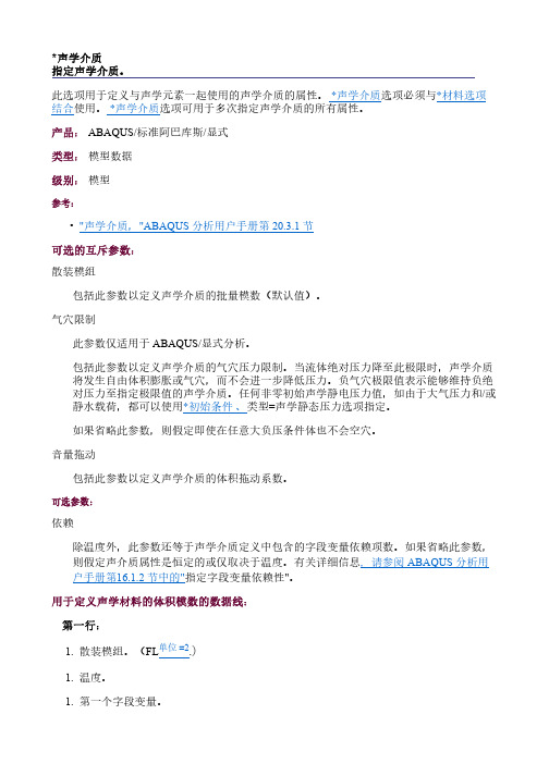
*声学介质指定声学介质。
此选项用于定义与声学元素一起使用的声学介质的属性。
*声学介质选项必须与*材料选项结合使用。
*声学介质选项可用于多次指定声学介质的所有属性。
产品:ABAQUS/标准阿巴库斯/显式类型:模型数据级别:模型参考:•"声学介质,"ABAQUS 分析用户手册第 20.3.1 节可选的互斥参数:散装模组包括此参数以定义声学介质的批量模数(默认值)。
气穴限制此参数仅适用于ABAQUS/显式分析。
包括此参数以定义声学介质的气穴压力限制。
当流体绝对压力降至此极限时,声学介质将发生自由体积膨胀或气穴,而不会进一步降低压力。
负气穴极限值表示能够维持负绝对压力至指定极限值的声学介质。
任何非零初始声学静电压力值,如由于大气压力和/或静水载荷,都可以使用*初始条件、类型=声学静态压力选项指定。
如果省略此参数,则假定即使在任意大负压条件体也不会空穴。
音量拖动包括此参数以定义声学介质的体积拖动系数。
可选参数:依赖除温度外,此参数还等于声学介质定义中包含的字段变量依赖项数。
如果省略此参数,则假定声介质属性是恒定的或仅取决于温度。
有关详细信息,请参阅ABAQUS 分析用户手册第16.1.2 节中的"指定字段变量依赖性"。
用于定义声学材料的体积模数的数据线:第一行:1.散装模组。
(FL单位 =2.)1.温度。
1.第一个字段变量。
1.第二个字段变量。
1.等,最多六个字段变量。
后续行(仅在依赖项参数的值大于 6 时需要):1.第七个字段变量。
1.等,每行最多八个字段变量。
根据需要重复这组数据线,以将大宗模量定义为温度和其他预定义的字段变量的函数。
用于定义声学材料的气穴压力极限的数据线:第一行:1.气穴压力限制。
(FL单位 =2.)1.温度。
1.第一个字段变量。
1.第二个字段变量。
1.等,最多六个字段变量。
后续行(仅在依赖项参数的值大于 6 时需要):1.第七个字段变量。
1.等,每行最多八个字段变量。
Abaqus各功能模块入门讲解PPT课件

特征修改、删除等,很少用到 线、面、体分割工具,辅助网格划分 基准点、线、面及坐标系等 拓扑修改等,辅助网格划分
网格控制 网格密度 网格划分
网格质量检查
.
L2.19
PARTITION CELL
Define Cutting Plane
定义切割平面的方法: ➢一点一法线 ➢三点 ➢一点一边(点要在边上,该边垂直于定义的切割平面)
SI m N kg s Pa J Kg/m3 m/s2
SI(mm) mm
US Unit in
N
1bf
T (103kg)
1bf s2/in
s
s
MPa mJ (10-3J)
t/mm3 mm/s2
psi in 1bf 1bf s2/in4
.
L2.3
分析流程九步走
1、几何建模 Part 2、划分网格 Mesh 3、特性设置 Property 4、建立装配体 Assembly 5、定义分析步 Step 6、相互作用 Interaction 7、载荷边界 Load 8、提交运算 Job 9、后处理 Visualization
ABAQUS仿真分析培训
.
L2.1
模型操作
Ctrl+Alt+鼠标左键 旋转模型
Ctrl+Alt+鼠标中键 平移模型
Ctrl+Alt+鼠标右键 缩放模型
.
L2.2
单位一致性
CAE软件其实是数值计算软件,没有单位的概念。
Length Force Mass Time Stress Energy Density Ace
Material管理器的功能完全可以在窗口左侧模型树的右键快捷菜单实现。
Abaqus频响分析完整过程

图 2 装配体示意图 【2】设置为线性摄动下的直接动态频响分析(如图 3),设置分析频率及步长(如 图 4)设置时要考虑实际需要,力求将所需频率包括到分析中。
1
图 3 分析步的选择
图 4 分析频率的设置 【3】定义接触关系:用“Tie”连接方式将两个部件的接触面进行绑定连接;找
图 6 载荷及约束情况 【6】网格划分和求解:网格划分与模态分析等完全相同,划分完网格后提交计 算即可,提交计算时注意设置内存使用情况和 CPU 并行计算情况。
3
2 分析结果
图 7 1166 Hz 时结构的响应情况
图 8 1687 Hz 时结构的响应情况
图 9 1792 施加在参考点上的集中力如果实际工况下的集中力载荷的关系可以知道则按照已知数据施加如果不知道那么施加一个转子转动平面内指向或背离结构最长延伸方向的载荷以起到激起远场结构响应的效果
Abaqus 频响分析
1 基本操作步骤
【1】启动 Abaqus 软件,模型,导入时将模型的长度单位缩放为 m(如图 1 所示)。 定义为压铸铝合金材料,即密度:2700kg/m3,弹性模量:72GPa,泊松比:0.33。 然后将两个部件装配在一起(如图 2 所示)。
出外转子的中心点,创建一个参考点 ,然后通过“
”连接方式将
外转子的中心点与实际工况中和外转子外壁面接触的面进行耦合连接,以方便施
加激励。接触关系如图 5 所示。
2
图 5 接触关系 【4】定义载荷及约束:约束情况和模态分析相同,载荷为施加在参考点上的集 中力,如果实际工况下的集中力载荷的关系可以知道,则按照已知数据施加,如 果不知道,那么施加一个转子转动平面内指向或背离结构最长延伸方向的载荷, 以起到激起远场结构响应的效果。载荷和约束情况如图 6 所示。
声学超材料的声振耦合数值分析
声学超材料的声振耦合数值分析李辉;李旭东【摘要】Based on definite element software ABAQUS,coupling model of acoustics metamaterial with pe-riodicity is built for the purpose of studying the effect of acoustic vibration coupling on structural displace-ment of acoustics metamaterial.When acoustics metamaterial is under acoustic-vibration recombination,fi-nite element model of acoustics metamaterial is simulated in computer with both acoustic and vibration ac-tion by ABAQUS acoustics finite element method and coupled acoustic-structural analysis.The result shows that structural displacement respond of metamaterial under sound-vibration recombination is bigger than that under single sound or vibration.It gives the rules that acoustic vibration coupling affects metama-terial structural displacement,so that ABAQUS can simultaneously simulate value under acoustic vibration recombination.%为了研究声振耦合对声学超材料结构位移响应的影响,以有限元软件ABAQUS为设计平台,建立具有周期性结构的声学超材料耦合模型.当声学超材料结构经受声-振复合环境激励时,通过ABAQUS声学有限元法和声固耦合算法,对声学超材料的有限元模型在声音、振动共同作用下进行计算机仿真.结果表明:声振复合环境激励下的超材料结构位移响应比声、振单独激励下位移叠加后的结果要大.揭示出声振耦合对超材料结构位移响应的影响规律,实现了ABAQUS软件同时对声振复合环境进行数值模拟.【期刊名称】《甘肃科学学报》【年(卷),期】2017(029)006【总页数】6页(P35-40)【关键词】有限元;声学超材料;声振耦合;位移;数值模拟【作者】李辉;李旭东【作者单位】兰州理工大学省部共建有色金属先进加工与再利用国家重点实验室,甘肃兰州 730050;兰州理工大学省部共建有色金属先进加工与再利用国家重点实验室,甘肃兰州 730050【正文语种】中文【中图分类】TB39“超材料”(metamaterials)是21世纪以来出现的一类新材料,通过人工的微结构单元构成复合结构或者复合材料并呈现出天然材料所不具备的超常物理性质。
R005ABAQUS资料-ACOU-WK01-AirDuct
Workshop 1Acoustic Evaluation of a Simple Air Duct SectionKeywords VersionNote: This workshop provides instructions in terms of the Abaqus Keywords interface. If you wish to use the Abaqus GUI interface instead, please see the “Interactive” version of these instructions.Please complete either the Keywords or Interactive version of this workshop.GoalsWhen you complete this workshop, you will be able to:•Determine the natural frequencies of an acoustic domain.•Determine the steady-state dynamic response of an acoustic system.•Define a classical acoustic plane-wave absorbing boundary.•Define acoustic excitation loads.•View real and imaginary components of acoustic pressure with Abaqus/Viewer.•Use Abaqus/Viewer to create path plots of acoustic output data.IntroductionA simple acoustic model of a section of air duct will be used to introduce some of the basic analysis techniques that can be applied to an acoustic mesh. In this workshop you will add important modeling details to complete the supplied analysis input file that already contains basic modeling data such as node, element, and material definitions, for the air duct section shown in Figure W1–1. The model for this workshop represents only the air inside the duct. Therefore, the acoustic natural boundary condition of infinite impedance at a mesh boundary implies rigid duct walls. You will perform natural frequency extraction analyses with different sets of acoustic boundary conditions assigned to the ends of the duct. You will then perform a series of steady-state dynamic response analyses on the model using different excitation methods. The steady-state dynamic analyses will also include the definition of acoustic plane-wave absorbing boundary impedance at one end of the duct to investigate postprocessing of traveling waves for frequency-domain solutions.The air duct section model shown in Figure W1–1 is supplied to you in terms of an input file, which uses the Abaqus parametric input capability. The parameter values defined in the input file should not be changed for this workshop. However, after completion of this workshop you may want to consider modifying the meshing parameters to performW1.2 additional convergence and accuracy studies. The air duct section is 4.25 m long and has a rectangular cross-section that is 0.2 m by 0.125 m. The acoustic medium is air with a density of 1.225 kg/m3 and a sound speed of 340 m/s. Thus, the effective bulk modulus is 141610 Pa. The model is designed to provide reasonable quantitative results for analyses up to 400 Hz and utilizes first-order acoustic elements that are 0.085 m long. This mesh refinement corresponds to 10 elements (nodal divisions) per acoustic wavelength at a response frequency of 400 Hz. The largest cross-sectional dimension of the duct is significantly less than one-half the 400 Hz acoustic wavelength; therefore, the duct cross-section can be modeled with a single element.Figure W1–1 Model of a simple air duct section.Note: In general, second-order acoustic elements are more accurate than first-order acoustic elements for the same mesh nodal density. However, first-order elements can provide nearly as good an approximation to a sinusoidal acoustic pressure wave as can second-order elements as long as the nodal distributions are similar. Therefore, when performing acoustic analyses in which determining the pressure field is of primary interest, first-order elements are often used because they are easier to work with in terms of meshing, defining acoustic loads, and input file editing. The main advantage of second-order acoustic elements is that they provide for a piecewise linear approximation of the pressure gradients (and, thus, the particle velocities), while the first-order elements produce a piecewise constant approximation. Therefore, for meshes with similar nodal densities, the second-order elements will provide significantly better quantitative results for items such as acoustic intensity (power)W1.3 that require accurate estimates of pressure gradients and particle velocities. Using first-order acoustic elements to determine a pressure field is analogous to using first-order stress-displacement elements to determine stiffness, while using second-order acoustic elements to determine acoustic intensity is analogous to using second-order stress-displacement elements to determine a stress/strain concentration.Case 1: Natural frequency extraction (rigid-rigid ends)The first analysis involves extracting the natural frequencies of the air duct section shown in Figure W1–1 for the case where both ends of the duct utilize the natural boundary condition associated with an acoustic mesh. Therefore, for this case no *BOUNDARY or *CLOAD options are applied to the acoustic pressure degree of freedom. The natural boundary condition associated with the surface of an acoustic mesh corresponds to infinite boundary impedance. The mesh boundary can therefore be envisioned as an infinitely rigid surface.1.Enter the working directory for this workshop:../acoustics/keywords/workshop12.The file acoust-ws1-template.inp contains a parametric model of the airduct section. Copy acoust-ws1-template.inp to a file named ws1-1.inp.Open ws1-1.inp in a text file and review its contents.3.Add the *STEP option along with an appropriate descriptive subheading.4.Add the *FREQUENCY option to extract the model’s natural frequencies. It isrecommended that the Lanczos eigensolver be selected via the EIGENSOLVERparameter. The extraction of natural frequencies for an acoustic mesh in realworld problems will likely involve relatively large models, for which the Lanczoseigensolver is more efficient than the subspace iteration eigensolver. In addition,the Lanczos eigensolver will allow you to select a precise frequency range for theeigenvalue extraction. Extract the natural frequencies in the range from 5 Hz to400 Hz with a shift point corresponding to 100 Hz.*FREQUENCY, EIGENSOLVER=LANCZOS25, 5.0, 400.0, 10000.05.Basic output requests for this analysis are contained in the input file and do notneed to be modified. However, note that the output variable identifier for theacoustic pressure is POR.6.Save the modified input file ws1-1.inp and run the Abaqus/Standard analysis.7.Review the printed output file ws1-1.dat in a text editor. Compare the naturalfrequencies listed in the Eigenvalue Output table to the exact classical valuesfor this problem. The classical solution is for a fundamental mode of 40 Hz withan interval of 40 Hz between successive modes.8.After the analysis completes, start an Abaqus/Viewer session and open the outputdatabase file ws1-1.odb. View the acoustic mode shapes by creating contourplots of the pressure variable POR (Plot→Contours).W1.4 9.Define a path along the length of the duct section and create a plot of POR alongthis path using the procedure below.a.In the Results Tree, double-click Paths.b.In the Create Path dialog box, accept the default path name (Path-1) andtype (Node list). Click Continue.c.In the Edit Node List Path dialog box, click Add Before.d.In the viewport, select the start and end points for the path, as shown inFigure W1–2. Click Done in the prompt area.e.The table in the Edit Node List Path dialog box now contains the selectednode labels. Click OK to complete the path definition.f.In the Results Tree, double-click XYData.g.In the Create XY Data dialog box, choose Path and click Continue.h.In the XY Data from Path dialog box, toggle on Include intersections toobtain X–Y data at locations where the path intersects the model as well asat the points that make up the path.i.In the Y Values portion of the XY Data from Path dialog box, clickStep/Frame. In the Step/Frame dialog box that appears, choose the modeof interest and click OK.j.In the XY Data from Path dialog box, click Plot to generate the path plot.Figure W1–2 contains examples of both a contour and a path plot for the fifthmode.Figure W1–2 Fifth acoustic mode shape of the air duct section with rigid-rigid ends. Path start (node 2)Path end (node 202)Case 2: Natural frequency extraction (rigid-free ends)As stated earlier, the natural boundary condition associated with the surface of an acoustic mesh corresponds to infinite boundary impedance. This implies that the acoustic particle velocity normal to the boundary surface is zero. The boundary surface can, therefore, be thought of as rigid. The natural boundary condition is characterized by a zero pressure gradient, as illustrated in the Case 1 analysis by the path plot shown in Figure W1–2. Assigning a value to the acoustic pressure degree of freedom at a bounding surface represents a kinematic boundary condition and corresponds to zero boundary impedance. This type of boundary condition allows acoustic particles to move freely across the bounding surface. The acoustic particle velocity at the bounding surface, characterized by the pressure gradient, is then unknown in a manner analogous to a reaction force in structural mechanics. For this analysis case you will determine the natural frequencies of the air duct section in which one end has infinite boundary impedance (rigid) and the other has zero boundary impedance (free).1.Copy your Case 1 input file (ws1-1.inp) to a file named ws1-2.inp and openthe new file in a text editor.2.Apply a zero pressure boundary condition (kinematic) to the nodes at End 1 of theair duct section (see Figure W1–1). The BOUNDARY option is used withdegree of freedom 8 (pressure) set to zero for the node set DUCT_END1.*BOUNDARYnode_number_or_set, 8, 8, 0.03.Save the modified input file and run the Abaqus/Standard analysis.4.Review the printed output file ws1-2.dat in a text editor. Compare the naturalfrequencies listed in the Eigenvalue Output table to the exact classical values for this problem. The classical solution is for a fundamental mode of 20 Hz withan interval of 40 Hz between successive modes.5.After the analysis completes, open the output database file ws1-2.odb inAbaqus/Viewer. View the acoustic mode shapes by creating contour plots of thepressure variable POR. Define a path along the length of the duct section andcreate a plot of POR along this path. Figure W1–3 contains examples of both acontour and a path plot for the fifth mode.Figure W1–3 Fifth Acoustic Mode Shape of the Air Duct Section with Rigid-Free Ends. Path start (node 2)Path end (node 202)Case 3: Steady-state dynamic analysis via pressure excitationIn most cases acoustic problems are studied in terms of their steady-state dynamic response. In real world problems complex energy-absorbing mechanisms dictate that steady-state dynamic analyses be performed. Natural frequency extraction analyses applied to acoustic domains take on a supporting role in providing insight into the general resonant behavior of acoustic volumes. Due to the general complexity of acoustic energy loss mechanisms, most acoustic steady-state dynamic analyses utilize a direct solution procedure in which the response is computed directly in terms of the physical degrees of freedom of the model. Therefore, the *STEADY STATE DYNAMICS, DIRECT procedure will be used throughout the acoustic analysis workshops.For this analysis case you will perform a steady-state dynamic simulation in which End 1 of the air duct section is excited by an oscillatory acoustic pressure of 1 Pa while End 2 remains rigid.1.Copy your Case 2 input file (ws1-2.inp) to a file named ws1-3.inp and openthe new file in a text editor.2.Change the descriptive subheading on the *STEP option and replace the*FREQUENCY option with the *STEADY STATE DYNAMICS option. Utilize the DIRECT parameter and set the FREQUENCY SCALE parameter to LINEAR.Request 80 solutions between 5 Hz and 400 Hz, with the bias set to 1.*STEADY STATE DYNAMICS, DIRECT, FREQUENCY SCALE=LINEAR5.0, 400.0, 80, 1.03.Modify the pressure boundary condition at End 1 of the air duct section to reflecta pressure magnitude of 1 Pa. This represents the free end of the air duct section.Include the REAL parameter to define the pressure as a real-valued quantity.*BOUNDARY, REALnode_number_or_set, 8, 8, 1.04.Request that history output for Ends 1 and 2of the air duct section be written tothe output database (.odb) file. The node set corresponding to End 2 isDUCT_END2.*OUTPUT, HISTORY, FREQ=1*NODE OUTPUT, NSET=node_number_or_setPOR,5.Save the modified input file and run the Abaqus/Standard analysis.6.After the analysis completes, open the output database file ws1-3.odb inAbaqus/Viewer.7.Create contour plots of the acoustic pressure magnitude and acoustic pressurephase angle for several driving frequencies. Use the Complex Form tabbed page of the Result Options dialog box (Result→Options) to choose the form of thedisplayed complex results. Notice that the phase angles are all essentially either 0 or 180 degrees, indicating that the solution is real-valued. This is due to the lackof any energy absorbing (damping) mechanisms in the model.8.In the Results Tree, expand the History Output container underneath the outputdatabase named ws1-3.odb. Create an X–Y plot of the acoustic pressureW1.9 magnitude (set in the Result Options dialog box if necessary) at both ends of the air duct section using the available history data.e [Ctrl]+Click to select multiple curves, then click mouse button 3;from the menu that appears, select Plot.b.Set the Axis Options (double-click either axis in the viewport) toutilize a logarithmic scale for the POR values and a linear scale for thedriving frequency.c.Your plot should look similar to the one shown in Figure W1–4. Thepeak response values correspond to the resonant natural frequencies ofthe rigid-free air duct section model. The anti-resonant (minimum)response values correspond to the natural frequencies of the rigid-rigidair duct section model. At the anti-resonant frequencies the responsepressure at the rigid end is essentially equal to the driving pressure.Figure W1–4 Steady-state dynamic response for the air duct section with anexcitation pressure of 1 Pa at the free end.W1.10Case 4: Steady-state dynamic analysis of a traveling plane waveThe previous steady-state dynamic analysis had no energy loss mechanism. However, for this analysis you will introduce an energy loss mechanism into the model by means of a plane-wave absorbing boundary impedance at End 2. The driving mechanism and output requests will be identical to those used in the Case 3 analysis.1.Copy your Case 3 input file (ws1-3.inp) to a file named ws1-4.inp and openthe new file in a text editor.2.Define a surface corresponding to End 2 of the air duct section with the*SURFACE option. This option must be placed in the model data portion of theinput file (before the first *STEP option). You can postprocess the Case 3 model(ws1-3.odb) to identify the End 2 element and face numbers you will need forthe surface definition.*SURFACE, NAME=surface_name, TYPE=ELEMENTelement_number_or_set, face_identifier_label3.Define a surface-based boundary impedance at End 2 by using the*SIMPEDANCE option. This option must be placed in the history data portion ofthe input file (between the *STEP and *END STEP options). Designate thesurface defined above on the data line. Leave the second field of the data lineblank.*SIMPEDANCEsurface_name,An alternative to the surface-based approach would be to use the element-based*IMPEDANCE option, where the impedance face is identified for individualelements and element sets.*IMPEDANCEelement_number_or_set, impedance_label_In4.Save the modified input file and run the Abaqus/Standard analysis.5.After the analysis completes, open the output database file ws1-4.odb inAbaqus/Viewer.6.Create contour plots of the acoustic pressure magnitude and acoustic pressurephase angle for several driving frequencies. Notice that the phase angles aredistributed in the range of -180 degrees to 180 degrees, indicating that complexsolutions consisting of both real and imaginary parts are present.7.Define a path along the length of the duct and create path plots of the acousticpressure magnitude and the real and imaginary components of the pressure. Inorder to select a particular component, use the Result Options dialog box and setthe desired component before creating the path plot. Utilize linear scales for thePOR value and the driving frequency. The results should look similar to thoseshown in Figure W1–5. This analysis represents the solution for a traveling planewave. Ideally, the pressure magnitude at all locations and frequencies would beequal to the excitation pressure. The wavelength associated with the drivingfrequency becomes apparent only when you are viewing the real and imaginaryW1.11 pressure components. Acoustic energy travels the length of the duct and isremoved by the plane-wave absorbing boundary, which can also be thought of as representing and infinitely long duct.Figure W1–5 Steady-state dynamic response for the air duct section with a plane-wave absorbing boundary at one end (traveling plane wave).8.Create an X–Y plot of the acoustic pressure magnitude at End 2 of the air ductsection using the available history data. Your plot should look similar to the one shown in Figure W1–6. A constant pressure at all locations and drivingfrequencies characterizes the classical solution for a traveling plane wave.Therefore, any pressure not equal to 1 on Figure W1–6 represents a measure ofthe error in the analysis. As the driving frequency increases, the finite elementapproximation to a sinusoidal pressure wave becomes less accurate and energybegins to reflect from the plane-wave absorbing boundary. This error is mostpronounced at driving frequencies that correspond to the natural frequencies ofthe acoustic mesh. Rigid-free ends, as presented in Case 2, characterize theacoustic mesh for this example.Figure W1–6 Steady-state dynamic response for the air duct section with aplane-wave absorbing boundary at one end.Case 5: Steady-state dynamic analysis via acoustic load excitationIn the preceding analyses, the acoustic mesh was excited by a known oscillatory pressure defined at a mesh boundary with the *BOUNDARY option. The acoustic pressure gradient at the boundary and, therefore, the acoustic particle motions, were unknown quantities. An alternative means of acoustic excitation is available for cases in which the acoustic particle motions are known. The *CLOAD option is used to define the acoustic particle motions at a node in terms of a quantity called the volume acceleration, while the pressure degree of freedom remains unknown. The volume acceleration is equal to the time rate-of-change of volume velocity, and the volume velocity can be thought of as the time rate-of-change of a volume that is created by a translating surface area. In steady-state dynamic analyses, the volume acceleration magnitude is equal to the volume velocity magnitude times the driving frequency (in radians) and leads the volume velocity by a phase angle of 90 degrees.In this analysis you will excite End 1 of the model from Case 4 with volume accelerations. The volume accelerations correspond to a traveling plane wave with a pressure magnitude of 1 Pa. Recall that acoustic impedance is defined as the acoustic pressure divided by the acoustic particle velocity. For a traveling plane wave it is equal to the acoustic medium’s specific acoustic impedance. Specific acoustic impedance is equal to the density times the sound speed and, for the air in the duct, it is equal to 416.5 rayl. Therefore, an acoustic particle velocity of 2.401E-3 m/s characterizes a 1 Pa traveling plane wave. The volume velocity associated with a traveling plane wave in the air duct section is equal to the acoustic particle velocity times the duct cross-sectional area. Thevolume velocity associated with each driven node at End 1 (4 nodes) is 1.5006E-5 m3/s, and the volume accelerations being applied with the *CLOAD option are equal to the nodal volume velocities times the driving frequency (in radians).1.Copy your Case 4 input file (ws1-4.inp) to a file named ws1-5.inp and openthe new file in a text editor.2.Update the descriptive subheading on the *STEP option and remove the*BOUNDARY option.e the *AMPLITUDE option to create a curve that represents the driving radianfrequency.*AMPLITUDE, NAME=curve_name1.0, 6.283185, 1000.0, 6283.185e the *CLOAD option to define the volume accelerations at the End 1 nodes.Include the IMAGINARY parameter to define the volume accelerations asimaginary. For a traveling plane wave the volume acceleration will lead theacoustic pressure and volume velocity by 90 degrees. Defining the volumeaccelerations as IMAGINARY will provide results that are consistent withanalysis Case 4.*CLOAD, IMAGINARY, AMPLITUDE=curve_namenode_number_or_set, 8, 1.5006E-55.Save the modified input file and run the Abaqus/Standard analysis.6.After the analysis completes, open the output database file ws1-5.odb inAbaqus/Viewer.7.Create contour plots of the acoustic pressure magnitude and acoustic pressurephase angle for several driving frequencies. Verify that the results are essentiallythe same as the Case 4 results by viewing the real and imaginary solutions at 180 Hz.8.Create an X–Y plot of the acoustic pressure magnitude at Ends 1 and 2 of the airduct section using the available history data. Your plot should look similar to theone shown in Figure W1–7. Notice that the relative difference between the driven end and the absorbing boundary end of the mesh is essentially the same as shown in Figure W1–6.Figure W1–7 Steady-state dynamic response for theair duct section excited via the CLOAD option.Note: Complete input files are available for your convenience. You may consult these files if you encounter difficulties following the instructions outlined here or if you wish to check your work. The input files are named acoust-ws1-1.inpacoust-ws1-2.inpacoust-ws1-3.inpacoust-ws1-4.inpacoust-ws1-5.inpand are available in the working directory for this workshop.。
关于利用ABAQUS软件模拟仿真摩擦振动问题的一些经验
关于利用ABAQUS软件模拟仿真摩擦振动噪声问题的一些经验小弟我学习使用ABAQUS解决摩擦振动噪声的问题已有数载,一直想写个这样的经验之谈与大家交流,总是时间仓促。
终于在闲暇之时,将本人的一些经验之谈与大家分享交流,同时希望大家能好好运用该软件解决实际问题。
文章分为4个部分第一:主要介绍摩擦振动噪声的一些基本知识及原理;第二:ABAQUS/Standard解决该问题的隐式分析法;第三:ABAQUS/Explicit解决该问题的显式分析法;第四:可能遇到的问题;Part 1:摩擦振动噪声的问题很普遍,国内外对这个问题的研究非常多,且主要集中在汽车或者列车制动装置上,比如鼓式制动器和盘式制动器等,这里不做详细叙述。
振动势必引起噪声,根据噪声频率的大小就有所谓的squeal noise/squeal/squeal等,很多理论也用于解释噪声产生的缘由,基本分为:stick-slip;摩擦力负斜率;模态耦合等等;在用有限元软件解决该问题时,隐式分析法主要采用的是模态耦合理论,当你证明出相邻两阶的振动频率达到一致时,此时的模态频率就是发生不稳定振动的频率;而显式分析法则是在一定时间内模拟运动的过程,可以显示出你所采集点的振动加速度,速度,或者位移等等。
下面,小弟将对这两个分析方法的操作做一个介绍。
Part 2: ABAQUS/Standard解决该问题的隐式分析法隐式分析法就是把整个运动的过程作为一个稳态准静态过程进行分析,大家都知道有摩擦,有接触的时候,这是一个高度非线性的过程,利用隐式分析法,把它当做一个静态的过程进行分析,可以用于预测这个系统的不稳定振动的频率,这对很多CAE工程师来说是非常重要的。
下面小弟将具体介绍一下操作步骤。
Step 1:当然,肯定就是建立模型了,简单的模型ABAQUS完全可以轻松解决,如果遇到负责的模型了,Proe等等三维软件就行了,只是需要另存为XT格式,导入ABAQUS里面,模型尽量准确,但是无关的位置,能够简化就尽量简化,因为我们需要做的是有限元分析,网格划分好坏是觉得一个计算能否顺利的主要因素,所以,考虑清楚好再建立模型,it is necessary!:Step 2:赋予材料属性,这个找个参考书,一看就会了。
Abaqus模块介绍

美国 ABAQUS 软件公司北京代表处华贸中心 2 号写字楼,707-709 室 中国,北京 100016 电话:(8610) 6536 2345 传真:(8610) 6598 9050ABAQUS模块简介ABAQUS 有两个主分析模块——ABAQUS/Standard 和 ABAQUS/Explicit,ABAQUS 也包含一个具 有交互作用的图形模块——ABAQUS/CAE,他提供了 ABAQUS 图形界面的交互作用工具。
ABAQUS/CAE(前后处理) ABAQUS/CAE 是 ABAQUS 有限元分析的前后处理模块,也是建模、分析和仿真的人机交互平台。
该模块根据结构的几何图形生成网格,将材料和截面的特性被分配到网格上,并施加载荷和边界条件。
该模块可以进一步将生成的模型投入到后台的分析模块运行,对运行情况进行监测,并对计算结果进行 后处理。
ABAQUS/CAE 的后处理支持 ABAQUS 分析模块的所有功能,并且对计算结果的描述和解释提 供了范围很广的选择,除了通常的云图,等值线和动画显示之外,还可以用列表,曲线等其他常用工具 的来完成工程显示。
该模块的许多独特功能与特点,例如 CAD 建模方式、参数化建模、适应设计者要求 的数据管理系统等极大的方便了 ABAQUS 的使用者。
ABAQUS/Standard(通用程序) ABAQUS/Standard 是一个通用分析模块,它能够求解广泛的线性和非线性问题,包括结构的静态、 动态、 热和电反应等。
对于通常同时发生作用的几何、 材料和接触非线形采用自动控制技术处理。
ABAQUS 拥有 CAE 工业领域最为广泛的材料模型,它可以模拟绝大部分工程材料的线形和非线形行为,而且任何 一种材料都可以和任何一种单元或复合材料的层一起用于任何合适的分析类型。
ABAQUS/Explicit(显示分析) ABAQUS/Explicit 是利用对事件变化的显示积分求解动态有限元方程。
6abaqus里的单词翻译,包括音标,方便记忆
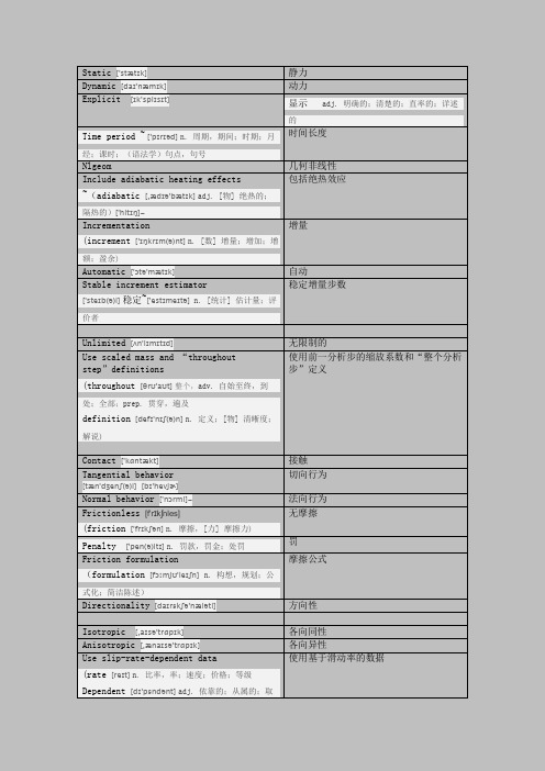
Static ['stætɪk]静力Dynamic [daɪ'næmɪk]动力Explicit[ɪk'splɪsɪt]∙显示adj. 明确的;清楚的;直率的;详述的∙Time period ~ ['pɪrɪəd]n. 周期,期间;时期;月经;课时;(语法学)句点,句号时间长度Nlgeom 几何非线性Include adiabatic heating effects∙~(adiabatic[,ædɪə'bætɪk]adj. [物] 绝热的;隔热的)['hitɪŋ]~包括绝热效应Incrementation∙(increment['ɪŋkrɪm(ə)nt]n. [数] 增量;增加;增额;盈余)增量Automatic['ɔtə'mætɪk]自动Stable increment estimator∙['steɪb(ə)l]稳定~['estɪmeɪtə]n. [统计] 估计量;评价者稳定增量步数Unlimited[ʌn'lɪmɪtɪd]无限制的Use scaled mass and “throughoutstep”definitions∙(throughout[θrʊ'aʊt]整个,adv. 自始至终,到处;全部;prep. 贯穿,遍及∙definition [defɪ'nɪʃ(ə)n]n. 定义;[物] 清晰度;解说) 使用前一分析步的缩放系数和“整个分析步”定义Contact['kɑntækt]接触Tangential behavior[tæn'dʒenʃ(ə)l][bɪ'hevjɚ]切向行为Normal behavior['nɔrml]~法向行为Frictionless[f'rɪkʃnles]∙(friction['frɪkʃən]n. 摩擦,[力] 摩擦力)无摩擦∙Penalty['pen(ə)ltɪ]n. 罚款,罚金;处罚罚Friction formulation∙(formulation[fɔːmjʊ'leɪʃn]n. 构想,规划;公式化;简洁陈述)摩擦公式Directionality[daɪrɛkʃə'næləti]方向性Isotropic[,aɪsə'trɑpɪk]各向同性Anisotropic[,ænaɪsə'trɑpɪk]各向异性Use slip-rate-dependent data∙(rate[reɪt]n. 比率,率;速度;价格;等级∙Dependent[dɪ'pɛndənt]adj. 依靠的;从属的;取决于…的)使用基于滑动率的数据Use contact-pressure-dependent data 使用依赖接触压力的数据摩擦系数Friction coeff∙(coeff[kəuf]n. 多项式系数)Shear stress[ʃɪə]~剪应力Pressure-overclosure ~[əʊvək'ləʊʒər]压力过盈∙(closure ['kləʊʒə]n. 关闭;终止,结束∙vt. 使终止)约束执行方法Constraint enforcement method∙(enforcement [ɪn'forsmənt]n. 执行,实施;强制∙Method ['meθəd]n. 方法;条理;类函数∙adj. 使用体验派表演方法的)Allow separation after contact允许接触后分离∙(Allow[ə'laʊ]vt. 允许;给予;认可vi. 容许;考虑∙Separation [sepə'reɪʃ(ə)n]n. 分离,分开;间隔,距离;[法] 分居;缺口)Coupling['kʌplɪŋ]耦合接触领域Contact domain∙(domain [də(ʊ)'meɪn]n. 领域;域名;产业;地产)排除的表面对Excluded surface pairs∙(Exclude [ɪk'skluːd; ek-]vt. 排除;排斥;拒绝接纳;逐出)Exterior[ɪk'stɪərɪə; ek-]∙adj. 外部的;表面的;外在的∙n. 外部;表面;外型;外貌Segments['segm(ə)nt]∙vi. 分割n. 段;部分vt. 分割属性指派Attribute assignment∙(Attribute [ə'trɪbjut]n. 属性;特质∙vt. 归属;把…归于∙assignment[ə'saɪnmənt]n. 分配;任务;作业;功课)力学约束公式化Machanical constraint formulation(Machanical[məˈkænɪkl]adj. 机械的,机械学的; 呆板的; 体力的; 手工操作的;Kinematic contact method运动摩擦法∙(Kinematic[,kɪnə'mætɪk]adj. [力] 运动学上的,[力] 运动学的)有限滑移Finite sliding∙(Finite ['faɪnaɪt]adj. 有限的;限定的n. 有限之物∙Sliding ['slaɪdɪŋ]∙Clearance['klɪrəns]n. 清除;空隙过盈量∙Procedure[prə'sidʒɚ]n. 程序,手续;步骤步骤∙Frequency['frikwənsi]n. 频率;频繁频率∙Interval['ɪntəv(ə)l]n. 间隔;间距;幕间休息间隔场输出:S, Stress components and invariantsS,应力分量和不便量∙(component [kəm'ponənt]adj. 组成的,构成的∙n. 成分;组件;[电子] 元件∙invariant [ɪn'veərɪənt]adj. 不变的∙n. [数] 不变量;[计] 不变式PE,塑性应变分量PE, Plastic strain components∙(Plastic ['plæstɪk]adj. 塑料的;(外科)造型的;可塑的;n. 塑料制品;整形;可塑体PEEQ,等效塑性应变PEEQ, Equivalent plastic strain∙(Equivalent [ɪ'kwɪvələnt]adj. 等价的,相等的;同意义的∙n. 等价物,相等物PEMAG, Plastic strain magnitudePEMAG,塑性应变∙(magnitude ['mæɡnɪtud]n. 大小;量级;[地震] 震级;重要;光度LE,对数应变分量LE, Logarithmic strain components∙(Logarithmic [lɔɡə'rɪðmɪk]adj. 对数的位移、速度、加速度Displacement/Velocity/Acceleration∙(Velocity [və'lɑsəti]n. [力] 速率;迅速;周转率∙Acceleration [əkselə'reɪʃ(ə)n]n. 加速,促进;[物]加速度U,位移和转动U,Translation and rotations∙(rotation [rə(ʊ)'teɪʃ(ə)n]n. 旋转;循环,轮流UT,Translations UT,平移UR,Rotations UR,旋转作用力/反作用力Forces/Reactions∙(Reaction [rɪ'ækʃən]n. 反应,感应;反动,复古;反作用RF,Reaction forces and moments RF,反作用力和力矩CF,Concentrated forces and momentsCF,集中力和弯矩∙(Concentrate ['kɑnsn'tret]vi. 集中;浓缩;全神贯注;聚集∙vt.集中;浓缩∙n. 浓缩,精选;浓缩液CSTRESS, Contact stress CSTRESS,接触应力CDISP,接触位移CDISP, Contact displacements∙(Contact ['kɑntækt]n. 接触,联系∙vt.使接触∙vi. 联系,接触Evenly spaced time intervals均匀时间间隔∙(Evenly ['ivnli]adv. 均匀地;平衡地;平坦地;平等地∙Spaced [spest]adj. 隔开的;以规定距离排列的;间隔排列的∙v. 隔开;空出(space的过去分词)每x个时间单位Every x units of time∙(unit ['junɪt]n. 单位,单元;装置;[军] 部队;部件Concentrated force 集中力Moment 弯矩Pressure 压力Surface traction表面载荷∙(traction ['trækʃən]n. 牵引;[机][车辆] 牵引力∙Gravity['ɡrævəti]n. 重力,地心引力;严重性;庄严重力线性摄动Linear perturbation∙(perturbation [,pɜːtə'beɪʃ(ə)n]n. [数][天] 摄动;不安;扰乱∙Individually[ˌɪndɪˈvɪdʒuəli]adv. 个别地,单独地逐个对称/反对称/完全固定Symmetry/Antisymmetry/Encastre∙(Symmetry ['sɪmətri]n. 对称(性);整齐,匀称Antisymmetry['æntɪsɪmɪtrɪ]n.反对称性Encastre[en'kɑ:stər]n. 端部固定∙Maintain[men'ten]∙vt. 维持;继续;维修;主张;供养Subsequent['sʌbsɪkwənt]∙adj. 后来的,随后的Active ['æktɪv]∙adj. 积极的;活跃的;主动的;有效的;现役的Applicable ['æplɪkəbl]∙adj. 可适用的;可应用的;合适的Allocation [,ælə'keʃən]∙n. 分配,配置;安置estimate['estɪmeɪt]估计∙vi. 估计,估价∙n. 估计,估价;判断,看法∙vt.估计,估量;判断,评价Parallelization[pærəlɪlaɪ'zeɪʃn]并行Use multiple processors运行多个处理器∙(multiple ['mʌltəpl]adj. 多重的;多样的;许多的∙n. 倍数;[电] 并联∙processor ['prɑsɛsɚ]n. [计] 处理器;处理程序;加工者精度∙Precision[prɪ'sɪʒ(ə)n]n. 精度,[数] 精密度;精确∙adj. 精密的,精确的提交∙Submit[səb'mɪt]vt.使服从;主张;呈递∙vi. 提交;服从监控∙Monitor['mɒnɪtə]n. 监视器;监听器;监控器;班长∙vt.监控边界条件:速度/角速度Velocity/Angular velocity∙(Velocity [və'lɑsəti]n. [力] 速率;迅速;周转率∙Angular ['æŋgjʊlə]adj. [生物] 有角的;生硬的,笨拙的;瘦削的Acceleration/Angular acceleration 加速度/角加速度可视化:Render['rendə]渲染风格Wireframe['waiəfreim]线框变形缩放系数Deformation scale factor∙(Deformation [,diːfɔː'meɪʃ(ə)n]n. 变形Uniform['junɪfɔrm]一致Nonumiform 不一致可见边Visible edges∙(Visible ['vɪzəbl]adj. 明显的;看得见的;现有的;可得到的∙n. 可见物;进出口贸易中的有形项目外部边Exterior edges∙(Exterior [ɪk'stɪərɪə; ek-]adj. 外部的;表面的;外在的∙n. 外部;表面;外型;外貌ODB display options:Refinement level细化精度∙(Refinement [rɪ'faɪnmənt]n. 精制;文雅;[化工][油气][冶] 提纯∙Level ['lev(ə)l]n. 水平;标准;水平面∙adj. 水平的;平坦的;同高的∙vi. 瞄准;拉平;变得平坦∙vt.使同等;对准;弄平∙Coarse[kɔrs]adj. 粗糙的;粗俗的;下等的稍粗极粗Extra coarse∙(Extra ['ekstrə]adv. 特别地,非常;另外∙n. 临时演员;号外;额外的事物;上等产品∙adj. 额外的,另外收费的;特大的中∙Medium['midɪəm]adj. 中间的,中等的;半生熟的∙n. 方法;媒体;媒介;中间物Fine 稍细Extra fine 极细辅助显示∙Idealizations[aɪ'dɪəlɪ'zeʃən]n. 理想化;理想化的事物考虑未激活的单元Account for deactivated elements∙(Account [ə'kaʊnt]n. 账户;解释;账目,账单;理由vi. 解释;导致;报账∙vt.认为;把…视为∙deactivate[di'æktə,vet]vt.使无效;使不活动;遣散;复员Mirror/Pattern镜像/图样∙(Pattern ['pæt(ə)n]n. 模式;图案;样品∙vt.模仿;以图案装饰∙vi. 形成图案Pattern 模式Pattern CSYS 阵列坐标系∙Rectangular[rek'tæŋgjʊlə]adj. 矩形的;成直角的直角Circular 圆形云图绘制选项:Contour type 云图类型Isosurface 等值表面离散∙Discrete[dɪ'skrit]adj. 离散的,不连续的∙n. 分立元件;独立部件Interval type 间隔类型Log 对数User-defined用户定义∙(defined [dɪ'faɪnd]adj. 有定义的,确定的;清晰的,轮廓分明的∙v. 使明确;给...下定义;使...的轮廓分明(define的过去分词)显示位置Show location∙(location [lə(ʊ)'keɪʃ(ə)n]n. 位置(形容词locational);地点;外景拍摄场地动画Animation[ænɪ'meɪʃ(ə)n]∙n. 活泼,生气;激励;卡通片绘制Use limits from all frames使用所有桢的最大最小值∙(frame [freɪm]n. 框架;结构;[电影] 画面∙vt.设计;建造;陷害;使…适合∙vi. 有成功希望∙adj. 有木架的;有构架的Animate scale factor 动画缩放系数Animate harmonic动画:谐振∙(harmonic [hɑr'mɑnɪk]adj. 和声的;谐和的;音乐般的∙n. [物] 谐波;和声动画选项:Frame rate 帧频率显示帧计数Show frame counter∙(counter ['kaʊntə]n. 柜台;对立面;计数器;(某些棋盘游戏的)筹码∙vt.反击,还击;反向移动,对着干;反驳,回答∙vi. 逆向移动,对着干;反驳∙adj. 相反的∙adv. 反方向地;背道而驰地积分点Integration point∙(Integration [ɪntɪ'greɪʃ(ə)n]n. 集成;综合质心Centroid['sentrɒɪd]∙n. 图心单元结点Element nodal∙(nodal ['nodl]adj. 节的;结的;节似的唯一结点的Unique nodal∙(Unique [jʊ'nik]adj. 独特的,稀罕的;[数] 唯一的,独一无二的∙n. 独一无二的人或物网格:近似全局尺寸Approximate global size∙(Approximate [ə'prɑksɪmət]vt.近似;使…接近;粗略估计∙vi. 接近于;近似于∙adj. [数] 近似的;大概的Curvature control曲率控制∙(Curvature ['kɜːvətʃə]n. 弯曲,[数] 曲率Maximum deviation factor最大偏离因子∙(deviation [diːvɪ'eɪʃ(ə)n]n. 偏差;误差;背离By fraction of global size按占全局尺寸的比例∙(fraction['frækʃ(ə)n]n. 分数;部分;小部分;稍微By absolute value 按绝对值∙(absolute['æbsəlut]adj. 绝对的;完全的;专制的∙n. 绝对;绝对事Hex 六面体Hex-dominated六面体为主∙(dominated['dɔmineitid]adj. 占主导地位的;强势的;占统治地位的;[数] 受控的∙v. 控制,支配;处于支配地位(dominate的过去式Tet 四面体楔形Wedge[wedʒ]∙vt.楔入;挤进;楔住∙vi. 楔入;挤进∙n. 楔子;楔形物;导致分裂的东西技术Technique[tek'niːk]∙n. 技巧,技术;手法结构Structured['strʌktʃəd]∙adj. 有结构的;有组织的∙v. 组织;构成(structure的过去分词);建造Medial axis 中性轴算法Appropriate [ə'prəʊprɪət]∙adj. 适当的∙vt.占用;拨出Linear 线性二次Quadratic[kwɑ'drætɪk]∙adj. [数] 二次的∙n. 二次方程式杂交公式Hybrid formulation∙(Hybrid['haɪbrɪd]n. 杂种,混血儿;混合物∙adj. 混合的;杂种的∙formulation[fɔːmjʊ'leɪʃn]n. 构想,规划;公式化;简洁陈述Reduced integration 减缩积分Incompatible modes 非协调模式Hourglass stiffness 沙漏刚度Viscosity 粘性Kinematic split 运动裂纹Second-order accuracy 二阶精度Distortion control 扭曲控制Hourglass control 沙漏控制Enhanced 增强Relax stiffness 松弛刚度Stiffness 刚度Viscous 粘性Combined 组合Element deletion 单元删除Max Degradation 最大下降Scaling factors 缩放系数Linear bulk viscosity 线性体积粘性Quadratic bulk viscosity 二次体积粘度优化:Freeze load regions 冻结载荷区域Freeze boundary condition regions 冻结边界条件区域Density update strategy 密度更新策略Conservative 保守Aggressive 激进Initial density 初始密度Maximun change per design cycle 每个设计循环的最大改变Convergence criteria 收敛准则首次设计循环作为评价标准First design cycle used to evaluatecriteriaCriteria to be fulfilled 要适应的准则Objective function delta criterion 目标函数delta准则Algorithm 算法Sensitivity-based 基于敏度Condition-based optimization 基于条件的优化Method 方法Material interpolation technique 材料内插技术Volume 体积Frozen area 冻结区域Member size 构件尺寸Memold control 脱模控制Rotational symmetry 轴对称Cyclic symmetry 循环对称Operator 运操作符Comparison operation 对比操作Previous iteration 前一次迭代Modify reference value by factor 按因子修改参考值Displacement by addition of material 有材料增加引起的位移Reduction 减少Total absolute displacement 总觉得位移Equivalent stress 等效应力任务区域内约束点的等效应力Equivalent stress of restricted pointsin task region载荷里的速度。
频响频响分析方法总结

[频响]频响分析方法总结(总1页)--本页仅作为文档封面,使用时请直接删除即可----内页可以根据需求调整合适字体及大小--频响分析,或者叫稳态动力学分析在abaqus中包括以下三种方法:直接稳态动力学分析(direct solution steady state dynamic analysis)模态稳态动力学分析(mode based steady state dynamic analysis)子空间稳态动力学分析(subspace projection steady state dynamic analysis)1)直接稳态动力学优点:在直接稳态动力学分析中,系统的稳态谐波响应是通过对模型的原始方程直接积分计算出来的。
如果分析的对象存在非对称刚度、包含模态阻尼以外的其他阻尼或者必须考虑粘弹性材料特性(频变特性),则不能提取特征模态的情况下,可以应用直接法进行稳态响应的计算和分析。
缺点:进行直接稳态动力学分析不需要提取系统的特征模态,而是在每个频率点对整个模型进行复杂的积分运算。
因此,对于具有大阻尼和频变特性的模型,应用直接法比模态分析方法精确,但是耗时较多。
2)模态稳态动力学分析模态稳态动力学分析方法是基于模态叠加法求解系统的稳态响应。
因此,在求解稳态响应之前必须先提取无阻尼系统的特征模态,也就是在说必须在step steady state dynamics,modal前加一步step frequency。
另外,必须确定需要保留的特征模态,以确保能够精确描述系统的动力学特性,也就是说如果是进行0-1000hz的分析,step frequency的number of eigenvalues requested选定的阶数的模态频率必须大于1000hz,简单的作法是这里选all……,下面的maximum……填入1000。
模态稳态动力学分析的特点:相较于直接法和子空间法分析速度快,耗时最少,计算精度低于直接法和子空间法,不适合于分析具有大阻尼特性的模型,不适合于分析具有粘弹性材料(频变特性)的模型。
- 1、下载文档前请自行甄别文档内容的完整性,平台不提供额外的编辑、内容补充、找答案等附加服务。
- 2、"仅部分预览"的文档,不可在线预览部分如存在完整性等问题,可反馈申请退款(可完整预览的文档不适用该条件!)。
- 3、如文档侵犯您的权益,请联系客服反馈,我们会尽快为您处理(人工客服工作时间:9:00-18:30)。
Copyright 2005 ABAQUS, Inc.
L6 .7
Structural-Acoustic Analysis with ABAQUS
Effect of Surface Treatments on Room Acoustics
Copyright 2005 ABAQUS, Inc.
Structural-Acoustic Analysis with ABAQUS
• The sphere is driven as a rigid body to excite mode 1 using the *BOUNDARY, TYPE=DISPLACEMENT option.
• A frequency range of 10 Hz to 204 Hz, corresponding to ka ~ 0.2 to 4.0 is analyzed using *STEADY STATE DYNAMICS, DIRECT.
L6 .9
Effect of Surface Treatments on Room Acoustics
– Example: Small room coupled to inlet and exhaust ducts. • Uniform forcing at inlet end. • Exhaust to exterior modeled using a small hemisphere of air and the spherical radiation condition. • At the frequency shown, the inlet excitation has excited a standing wave in the room.
• Nonconforming shell (S8R) and acoustic infinite element (ACIN3D4) meshes are used.
• Fluid-solid coupling through use of the *TIE option.
Copyright 2005 ABAQUS, Inc.
Copyright 2005 ABAQUS, Inc.
Structural-Acoustic Analysis with ABAQUS
L6 .14
Nonlinear Structural Behavior
– Structural analysis can include effects from several sources of nonlinearity: • Material nonlinearities – Examples: Metal plasticity, crushable foam • Geometric nonlinearities – Examples: Pre-tensioning of a cable, snap-through behavior of an arch • Contact nonlinearities – Contact is inherently nonlinear because the contact constraints are either on or off; they do not vary smoothly.
Sloshing
• Pressure magnitudes at 158.7 Hz
Copyright 2005 ABAQUS, Inc.
Structural-Acoustic Analysis with ABAQUS
Sloshing
• Pressure magnitude results
freq (Hz)
Structural-Acoustic Analysis with ABAQUS
Lecture 6
深 圳 ABAQUS培 训 深 圳 ANSYS培 训 深 圳 ANSYS http://www.xn cae.co m 深 圳 ABAQUS 深 圳 有 限 元 培训 ABAQUS培 训 ANSYS培 训
L6 .11
Copyright 2005 ABAQUS, Inc.
Structural-Acoustic Analysis with ABAQUS
Effect of Surface Treatments on Room Acoustics
– With acoustic treatment:
L6 .12
• A steel (r = 7800 kg/m3, E = 210 GPa, n = 0.3) spherical shell of
radius 1 m and thickness 0.05 m is immersed in an infinite volume of
air (r = 1.25 kg/m3, K = 128000 Pa, c = 320 m/s).
Copyright 2005 ABAQUS, Inc.
Structural-Acoustic Analysis with ABAQUS
Sloshing
Copyright 2005 ABAQUS, Inc.
Structural-Acoustic Analysis with ABAQUS
L6 .4
Sloshing
10.0000000 12.8569000 16.5300000 21.2524000 27.3239000 35.1301000 45.1664000 58.0699000 74.6598000 95.9893000 123.412000 158.670000 204.000000
ka
0.196349541 0.252444641 0.324565791 0.417289898 0.536503522 0.689777900 0.886840190
2.51404729 4.20443148 7.07835582 12.0302351 20.6920596 35.9879477 62.6105015 105.798479 166.273101 237.975417 317.622889 410.202606 524.385853
Байду номын сангаас
ka2 2 2 ka6 Analytical solution: P1 = rc2 u1 ka 2 ka2 2 2 (2ka)2
L6 .10
Copyright 2005 ABAQUS, Inc.
Structural-Acoustic Analysis with ABAQUS
Effect of Surface Treatments on Room Acoustics
– Add acoustic treatments to ceiling, wall, and floor of room:
• Spherical acoustic radiation in Mode 1 – Reference: Junger, M.C. and Feit, D., Sound, Structures, and Their Interaction, MIT Press, pp. 200-203, 1972. – Physical Description:
Copyright 2005 ABAQUS, Inc.
Structural-Acoustic Analysis with ABAQUS
Nonlinear Structural Behavior
Copyright 2005 ABAQUS, Inc.
Structural-Acoustic Analysis with ABAQUS
Copyright 2005 ABAQUS, Inc.
Structural-Acoustic Analysis with ABAQUS
Effect of Surface Treatments on Room Acoustics
– Acoustic-only mesh of room, ducts, and exterior; no treatment:
Additional Examples
Copyright 2005 ABAQUS, Inc.
Structural-Acoustic Analysis with ABAQUS
L6 .2
Overview
• Sloshing • Effect of Surface Treatments on Room Acoustics • Nonlinear Structural Behavior • Coupled Piezoelectric and Acoustic Analysis • Acoustics of a Truck Cab: Fully Coupled Analysis • Acoustics of a Truck Cab: Sequential Analysis • Summary
Copyright 2005 ABAQUS, Inc.
Structural-Acoustic Analysis with ABAQUS
L6 .15
Nonlinear Structural Behavior
– Multistep analysis • General analysis steps can have linear or nonlinear behavior. • The end condition of one general step provides the base state for the next general step. – If an earlier general step includes nonlinear behavior, the nonlinear solution is included in subsequent steps. • Acoustic analysis includes the effects of previous nonlinear general steps. – The most obvious effect is aligning the acoustic region with the deformed shape of the structure, including contact regions. – Less obvious is the change in material properties, such as stiffness.