频率输出温湿度传感器模块HTF3226LF
温湿度传感器介绍

DWTHI100-S02无线多功能综合传感器一、产品介绍1.1产品概述●本产品可以实时、准确的测量环境温度、环境相对湿度和照度,它能使用户对现场环境实现远程的数据采集和监测,大大减少人工工作量,突出便利性、准确性和实时性。
●本产品具有体积小、使用寿命长、无线信号传输距离远、环境适应性好、测量精度高、安装便捷、防水等特点,是一款高性价比的产品。
●本产品可广泛应用于仓储管理、生产制造、气象观测、科学研究以及日常生活等领域。
1.2 产品外观1.3技术参数1. 温度测量范围:-40℃~+125℃;2. 温度测量精度:±0.3℃±2.5%(rdg-25℃);3. 绝对湿度测量范围:1%RH~100%RH;4. 绝对湿度测量精度:<10%RH:±1.8%RH±20%(rdg-20%RH);10%RH~90%RH:±1.8%RH>90%RH:±1.8%RH±20%(rdg-90%RH);5. 工作环境温度:-20℃~+80℃;6. 信号调制方式:GFSK;7. 工作频率:2.45GHz;8. 无线通讯距离:>300米(2.45GHz、开阔地);9. 测量周期:30s(3.6V、典型值);10.平均功耗:<7μA(3.6V);11.电池寿命:≥6年;12.外壳材料:增强型耐高温ASA树脂;13.外形尺寸:45 mm×24 mm×18.5mm;14.重量:25g(含天线);15.防护等级:IP34;16.安装方式:螺丝固定或无痕泡棉双面胶粘贴。
1.4应用场所1、机房、厂房、仓库、无菌室;2、温室大棚、智能大棚;3、图书馆、档案馆、文物馆;4、生物制药;5、食品加工、储存场所;6、医卫场所;7、气象站;8、智能楼宇;9、其它需要监测温、湿、照度的场所。
1.5产品尺寸二、系统简介:2.1系统组成温、湿、照度在线监测系统组成原理如左图所示,它主要由管理中心(控制主机)、数据传输基站和无线多功能综合传感器组成。
温湿度检测模块的工作原理
温湿度检测模块的工作原理一、引言温湿度检测模块是一种常见的传感器模块,可以用来测量环境中的温度和湿度。
它广泛应用于家庭、办公室、工厂等场所,以及气象、农业等领域。
本文将详细介绍温湿度检测模块的工作原理。
二、温湿度检测模块的组成温湿度检测模块主要由传感器、放大电路、微处理器和显示屏等组成。
1. 传感器传感器是温湿度检测模块的核心部件,它能够将环境中的温度和湿度转化为电信号输出。
常见的温湿度传感器有热敏电阻式传感器和电容式传感器。
热敏电阻式传感器利用材料在不同温度下电阻值发生变化的特性来实现温度检测。
当环境温度发生变化时,热敏电阻的电阻值也会相应地发生变化,从而产生一个与环境温度相关联的电信号输出。
电容式传感器利用介质在不同湿度下介电常数发生变化的特性来实现湿度检测。
当环境湿度发生变化时,电容式传感器的电容值也会相应地发生变化,从而产生一个与环境湿度相关联的电信号输出。
2. 放大电路传感器输出的电信号较小,需要经过放大电路进行放大处理。
放大电路通常采用运放作为放大元件,可以将传感器输出的微弱信号放大到一定程度,以便后续处理。
3. 微处理器微处理器是温湿度检测模块的控制中心,它能够对传感器采集到的信号进行处理,并将结果显示在屏幕上。
微处理器通常采用单片机或者嵌入式系统芯片。
4. 显示屏显示屏是温湿度检测模块的输出部件,它能够将温度和湿度值显示出来。
常见的显示屏有液晶显示屏和数码管显示屏。
三、温湿度检测模块的工作原理温湿度检测模块工作原理如下:1. 传感器采集环境信息当温湿度检测模块开始工作时,传感器会自动采集环境中的温度和湿度信息,并将其转化为相应的电信号输出。
这些电信号经过放大电路放大处理后,会传输到微处理器中进行处理。
2. 微处理器对信号进行处理微处理器会将传感器采集到的温度和湿度信号进行数字化处理,并通过内部算法计算出相应的温度和湿度值。
这些数值会被存储在微处理器的内存中。
3. 显示屏显示温湿度值当用户需要查看当前环境的温湿度值时,微处理器会将计算出来的数值发送给显示屏,显示屏上就会显示出当前环境的温湿度值。
F65系列湿度及湿度-温度传感器使用说明书

F65 SeriesHUMIDITYAND HUMIDITY-TEMPERATURE TRANSMITTERS INSTRUCTION MANUALCONTENTS DESCRIPTION (3)OPERATION (4)Power Supply (4)Output Range (4)Temperature Operating Range and Temperature Limits (4)Humidity Limits (4)Temperature Compensation (4)Sensor Protection (5)Output Signals (5)Wiring Diagrams (6)Grounding (7)INSTALLATION (8)General Recommendations (8)Installation of the Base Plate (9)Installation of the Electronics Module (10)MAINTENANCE (11)Cleaning or Replacing the Dust Filter (11)Periodic Calibration Check (11)SPECIFICATIONS (13)PLEASE, READ THIS FIRST• Check the product for any physical damage that may have occurred during shipment. We carefully pack and routinely insure all shipments. If any damage has occurred, it is your responsibility to filea claim with the carrier, prior to returning the damaged product. Please note that our warranty doesnot cover damage during shipment.• See the label on the shipping box for information about the model number of the transmitter, the supply voltage as well as the type and range of the output signals. An identical label is also located under the printed circuit board.• Prior to installation, get fully familiarized with the operating limits of the product and with the installation instructions provided in this manual.• Do not unnecessarily remove the sensor protection (dust filter or slotted cap) from the probe. Both sensors (humidity and temperature) can be mechanically damaged by careless removal of the protection. The ROTRONIC HYGROMER humidity sensor looks like a small white paper tag. Do not remove from the probe!Each ROTRONIC instrument is carefully calibrated before shipment. No further adjustments should be required before installation. If you have any question or problem, please call our service department at 631/427-3898 and press 5 (or ask for extension 21).Transmitters of the F65 series are used to measure humidity or a combination of humidity and temperature in manufacturing areas, clean rooms, research laboratories and other industrial applications. The electronic circuitry is either of the 2-wire loop powered type or of the 3-wire type. Linearized output signals (DC current or voltage) are provided for transmission over a length of cable to a remote display, recorder, controller or data processing unit.The F65 series features the ROTRONIC HYGROMER capacitive humidity sensor. This well proven sensor offers exceptional durability and stability in all kinds of environments. This fact is reflected in the 3-year full warranty that covers the transmitters of the F65 series. Reliability is further enhanced by the easy-to-perform field calibration. Measurement accuracy and fast response are provided over the entire range of humidity conditions, even when the sensor is exposed to extremely high or low humidity over long periods of time. An electronic compensation circuit maintains the accuracy of humidity measurement at all temperatures.Models that measure both humidity and temperature, use an RTD Pt100 as the temperature sensor.F65 series transmitters include a base plate and a module (sensor and electronics) which plugs into the base plate. The base plate can be installed and wired without the module at the same time as general electrical work is being done. During that period of time, the module can safely be stored away. The F65 series is available in the following configurations:Model Measurement Circuit Type InstallationF2C-W65 Humidity 2-Wire Loop Powered Wall (Surface)FT2C-W65 Hum. + Temperature 2-Wire Loop Powered Wall (Surface)F2C-D65 Humidity 2-Wire Loop Powered Duct (Through Wall)FT2C-D65 Hum. + Temperature 2-Wire Loop Powered Duct (Through Wall)(Surface) F3V-W65 Humidity 3-Wire WallFT3V-W65 Hum. + Temperature 3-Wire Wall (Surface)F3V-D65 Humidity 3-Wire Duct (Through Wall)FT3V-D65 Hum. + Temperature 3-Wire Duct (Through Wall)Power SupplyTransmitters of the F65 series require the following supply voltage:• 2-Wire Transmitters: 10..35 VDC (depending on the load connected to the output)The minimum supply voltage can be determined as follows: V min = 10 V + [0.02 x Load (ohm)]. For the maximum load of 500Ω, the minimum supply voltage is 10 + [0.02 x 500] = 20 VDC. The maximum current consumption is 20 mA per circuit.• 3-Wire Transmitters: 10..35 VDC or 24 VACModels with a current output require a minimum of 15 VDC when the load connected to the output(s) is 500Ω. 3-Wire transmitters have a typical current consumption of 16 mA (Humidity only) or 32 mA (combined humidity and temperature).Output RangeThe range of the relative humidity output is 0 to 100%RH. The temperature output depends on the range specified when ordering (see label on shipping box and under the printed circuit board). Temperature Operating Range and Temperature LimitsThe F65 series can operate within 23 to 122°F (-5 to 50°C) at the electronics.The temperature operating range of models for surface (wall) installation is the same as the temperature limits of the electronics. For through wall (duct) installation models, the temperature limits at the sensor(s) are –22..158°F (-30..70°C).Operating the transmitter and/or its probe outside of the temperature limits can result in permanent damage.Humidity LimitsAs far as possible, avoid sudden condensation at the sensors. When measuring at high humidity, condensation may occur on the humidity sensor due to a sudden difference in temperature with the environment. This does not damage the sensor. However, this will produce an overflow reading (an output signal of more than 100 %RH) for as long as condensation is present on the humidity sensor. Temperature CompensationPractically every make of relative humidity sensor requires a compensation for the effect of temperature on the humidity output signal in order to measure accurately over a wide range of temperature conditions. In the specific case of an instrument using a capacitive sensor, compensation is required because the dielectric characteristics of both the water molecule and the hygroscopic polymer used in the sensor vary with temperature.The electronic circuit of the F65 series uses an NTC located next to the humidity sensor to provide automatic compensation for the effect of temperature on the humidity sensor. The temperature compensation uses normal room temperature as a reference. Because of this, calibration of the unit is done at normal room temperature rather than at the temperature of operation at the sensor.Sensor ProtectionTransmitters of the F65 series are supplied as a standard with a dust filter to protect the sensors.When using a transmitter in a clean environment with rapidly changing conditions, it is recommended to use a slotted cap with screen (available from ROTRONIC) as opposed to using a dust filter.Do not remove the dust filter or slotted cap.Output SignalsThe F65 series is available with the following output signals:• 2-Wire loop powered transmitters: 4-20 mAThe transmitter behaves as a variable load and adjusts the current flowing through the terminals as a function of relative humidity and temperature. The output signal may be read with any current sensing device having a maximum impedance of 500 ohms. When several devices are connected in series with the transmitter, the resulting impedance should not exceed 500 ohms, wiring included.• 3-Wire Transmitters: 0-20 mA, 4-20 mA, 0-1 V or 0-5 V. The output signal depends on the type specified when ordering. A label located inside the case cover shows the type of output signal for each unit..The output signals are linear and are consistent with the requirements of most data/signal processing instrumentation (panel meter, controller, computer card, etc.).Units with current outputs behave as a variable source of current and adjust the current flowing through the terminals as a function of relative humidity and temperature. The output signal may be read with any current sensing device having a maximum impedance of 500 ohms. When several devices are connected in series with the transmitter, the resulting impedance should not exceed 500 ohms, wiring included.Units with voltage outputs behave as a variable voltage source and adjust the voltage across the terminals as a function of relative humidity and temperature. The output signals may be read with any voltage sensing device having a minimum impedance of 100 kohms. When several devices are connected in parallel with the transmitter, the resulting impedance should not be less than 1000 ohms.Wiring DiagramsThe wiring diagram for transmitters that measure humidity only is as follows:3-Wire Transmitter with voltage output2-Wire Transmitter (4-20 mA output)Terminal number on base plateTerminal number on base plate3-Wire Transmitter with current output12Terminal number on base platenot used not usedThe wiring diagram for transmitters that combine humidity and temperature measurement is as follows:GroundingOperation of the F65 series does not require that the unit be electrically grounded. However, we recommend grounding the instrument, especially if the electronic circuits are subjected to a low humidity environment (less than 35 %RH).3-Wire Transmitter with voltage outputs2-Wire Transmitter (4-20 mA outputs) using two independent power suppliesTerminal number on base plateTerminal number on base plateTerminal number on base plate3-Wire Transmitter with current outputs2-Wire Transmitter (4-20 mA outputs)using a single power supplyINSTALLATION• Do not remove the dust filter or slotted cap from the probe. The sensor can easily be damaged when not protected.• The ROTRONIC HYGROMER humidity sensor has the appearance of a small white paper tag.Do not remove!General RecommendationsRelative humidity is extremely dependent on temperature. Proper measurement of relative humidity requires that the probe and its sensors be at exactly the temperature of the environment to be measured. Because of this, the location where you choose to install the probe can have a significant effect on the performance of the instrument. The following guidelines should guarantee good instrument performance:• Select a representative location: install the probe where humidity, temperature and pressure conditions are representative of the environment to be measured.• Provide good air movement at the probe: air velocity of at least 200 ft/ minute (1 meter/second) facilitates adaptation of the probe to changing temperature.• Avoid the following:(1)Close proximity of the probe to a heating element, a cooling coil, a cold or hot wall, direct exposure to sun rays, etc. (2) Close proximity of the probe to a steam injector, humidifier, direct exposure to precipitation, etc. (3) Unstable pressure conditions resulting from excessive air turbulence.• Immerse as much of the probe as possible in the environment to be measured.• Prevent the accumulation of condensation water at the sensor leads. Install the probe so that the probe tip is looking downward. If this is not possible, install the probe horizontally.Installation of the Base PlateThe base plate should be installed first, using screws with an approximate diameter of 5/32".IMPORTANT (Through wall installation only)In order to be able to use a calibrator for future calibration checks, an orifice should be provided at a distance of about 6” from the center of the base plate. Calibrators available from ROTRONIC require an orifice with a diameter of 13/16” (21 mm). We recommend that this orifice be equipped with a QMA-15 probe holder and a rubber stopper. The orifice will be used to insert the probe of the calibrator and to verify the readings of the transmitter.The base plate is supplied with one sealing cable grip. This cable grip provides effective sealing only with cables having the proper outside diameter. Preferably, use a cable with an outside diameter of 0.236 to 0.275 inch (6 to 7 mm) and with 18 AWG wires. Depending on the installation, you may have to use a cable with twisted pairs or a shielded cable to avoid interference.In order to determine the maximum length of cable that can be used to connect the transmitter to other devices, the first step is to find out what is the resistance per unit of length of the cable that you plan on using.. Current outputs: the maximum permissible cable length, connecting the unit to other devices, is determined by the total resistance resulting from the addition of the cable resistance and that of the devices connected in series with the unit. This resistance should not exceed 500 ohms.. Voltage outputs: the maximum cable length can be determined under consideration of the voltage drop caused by the current flowing to the devices connected to the unit. The voltage drop in thecable depends both on cable resistance and on the equivalent resistance of the devices connected in parallel to the unit. The total resistance connected to each unit output must at least be equal to 100 kohms. Cable resistance should not be more than 1/1000 of the load resistance.Avoid running the cables connecting the unit in the same conduit as 110 VAC power cables. If this cannot be avoided, a shielded cable or a cable with twisted wires may be required to prevent interference due to electromagnetic induction caused by switching.We generally recommend grounding, especially if the electronics will be subjected to a low humidity environment (35 %RH or less).Transmitter TypeTerminals Description (see base plate) 2-Wire, humidity only 1: not used2: not used3: (+) Supply Voltage 4: 4-20 mA (humidity)3-Wire, humidity only 1: (+) Supply Voltage2: (-) Supply Voltage and Common 3: not used4: (+) Humidity (current or voltage)2x2-Wire, humidity and temperature 1: (+) Supply Voltage2: 4-20 mA (temperature) 3: (+) Supply Voltage 4: 4-20 mA (humidity)3-Wire, humidity and temperature 1: (+) Supply Voltage2: (-) Supply Voltage and Common 3: (+) Temperature (current or voltage) 4: (+) Humidity (current or voltage)See also Wiring DiagramsInstallation of the Electronics ModuleOnce the base plate has been installed and wired, the plug-in module (sensor(s) and electronics can be inserted and secured with the screws provided. The transmitter is ready to operate.Example:Through wall installation.MAINTENANCECleaning or Replacing the Dust FilterThe dust filter should be cleaned from time to time, depending on the conditions of measurement. Cleaning should be done without removing the filter from the probe. Gently wipe the filter with a solution of water and mild detergent. If this does not remove most of the stains, the filter should be replaced. To do this, unscrew the filter from the probe.Before putting on a new dust filter, check the alignment of both sensors with the probe. The wires that connect the sensors to the probe are very thin and bend easily. If this happens, correct the alignment by holding the sensor very gently with a pair of small flat nosed pliers.Periodic Calibration CheckLong term stability of the humidity sensor is typically better than 1 %RH per year. For maximum accuracy, calibration of the unit should be verified every 6 to 12 months.Transmitters of the F65 series are equipped with a 5-pin keyed test connector that permits reading the signal(s) without interrupting the operation of the transmitter.Pop out ROTRONIC Label toaccess Connector and Calibration Pot(s) Square Single-turn Pot = Temp.Temp.Rectangular Multi-turn Pot = RHThrough WallTest Connector Pin # Wire Color Signal(+)1 Green Humidity(-)2 Yellow Humidityused3 Brown not4 White Temperature (+)(-)5 Gray TemperatureThe ROTRONIC A2C calibrator can be used to directly read the signal(s) provided by the test connector. The A2C comes with test cable AK3029-B used to connect the A2C with the transmitter.The humidity-temperature probe connected to the A2C provides the reference readings necessaryto check the accuracy of the F65 transmitter. As an alternative, any suitable reference instrumentmay be used and the signal(s) from the test connector can be read with a multimeter (use test cableAK3029-4P to connect the DVM to the transmitter).The signals from the test connector are as follows:• 2-Wire and 2x2-Wire Transmitters: 40..200 mV.• 3-Wire Transmitters: 0..1 VFor humidity, this corresponds to 0..100%RH. For temperature, this corresponds to the range specified when ordering the transmitter (see label on shipping box and under the printed circuit board).A one-point calibration check can be done by comparison between a reference instrument and thesignal(s) provided by the test connector. If an offset adjustment of the transmitter is required, use the potentiometer(s) located next to the test connector.Note: during a 1-point adjustment against a referenceprobe, make sure that both the reference probe andtransmitter are ventilated and provide enough time forboth to equilibrate.SPECIFICATIONSHumidity Sensor ROTRONIC HYGROMER C94Temperature Sensor (FT Models) Pt100 RTDOperating Temperature at Electronics 23..122°F (-5..50°C)Humidity Measuring Range 10..100 %RHHumidity Output Range 0..100%RHTemperature Measuring Range (FT Models) See temperature LimitsStandard Temperature Output Range (FT Models) 0..100°F or 0..100°CTemperature Limits at Sensors Wall Mount Models: 23..122°F (-5..50°C)Duct Mount Models: -22..158°F (-30..70°C) Output Signals (linear) F2C/FT2C: 4-20 mA (max. load 500Ω)F3V/FT3V: 0-5 V (min. load 1000 Ω)Accuracy at 68..77°F (20..25°C) ± 2%RH from 10 to 100%RH± 0.5°F (±0.3°C)Repeatability ± 0.3%RH and ±0.2°F (±0.1°C)Humidity Sensor Stability better than 1%RH over a yearResponse Time (without filter) 10 seconds (%RH and temperature) Calibration Potentiometers 1 for Humidity, 1 for TemperatureSupply Voltage F2C/FT2C: 10..35VDC; min. 10V + [0.02 x Load]F3V/FT3V: 15..35VDC/24VAC - 16/32 mA (F/FT) Sensor Protection PPS Dust Filter (wire mesh)Weight 0.7 lbs (300 g)Case Material ABSCase Protection DIN IP 65 (splash proof)。
数字温湿度传感器详情和代码
void RH(void) {
//主机拉低 18ms P2_0=0; Delay(180); P2_0=1; //总线由上拉电阻拉高 主机延时 20us Delay_10us(); Delay_10us(); Delay_10us(); Delay_10us(); //主机设为输入 判断从机响应信号
注:采样周期间隔不得低于1秒钟。
7、应用信息
7.1工作与贮存条件 超出建议的工作范围可能导致高达3%RH的临时性漂移信号。返回正常工作
条后,传感器会缓慢地向校准状态恢复。要加速恢复进程/可参阅7.3小节的“恢 复处理”。在非正常工作条件下长时间使用会加速产品的老化过程。 7.2暴露在化学物质中
电阻式湿度传感器的感应层会受到化学蒸汽的干扰,化学物质在感应层中 的扩散可能导致测量值漂移和灵敏度下降。在一个纯净的环境中,污染物质会缓 慢地释放出去。下文所述的恢复处理将加速实现这一过程。高浓度的化学污染会 导致传感器感应层的彻底损坏。 7.3光线
U8comdata|=U8temp;
//0
}//rof
}
//-------------------------------//-----湿度读取子程序 -----------//-------------------------------//----以下变量均为全局变量-------//----温度高 8 位== U8T_data_H-----//----温度低 8 位== U8T_data_L-----//----湿度高 8 位== U8RH_data_H----//----湿度低 8 位== U8RH_data_L----//----校验 8 位 == U8checkdata----//----调用相关子程序如下---------//---- Delay();, Delay_10us();,COM(); //--------------------------------
蔬菜大棚温度 湿度传感器检测系统的设计

应用价值 蔬菜大棚温度、湿度传感器检测系统的应用价值主要体现在以下几个方面: 1、提高蔬菜产量和质量:通过对大棚内温度和湿度的实时监测,可以及时 调整环境因素,为蔬菜提供最佳的生长条件,从而提高蔬菜的产量和质量。
2、节省人力成本:传统的大棚环境监测需要人工定时测量和记录数据,而 本系统可以实现自动化监测和控制,大大节省了人力成本。
1、系统能够实时准确地监测大棚内的温度,并稳定控制在适宜蔬菜生长的 范围内;
2、当温度超出预设范围时,系统能够及时启动报警装置进行报警,且报警 装置工作稳定可靠;
3、人机界面显示效果清晰明了,调整功能方便易用。
Hale Waihona Puke 参考内容二引言蔬菜大棚种植作为一种现代化的农业生产方式,已经在全球范围内得到了广 泛应用。大棚种植能够为蔬菜提供适宜的生长环境,提高产量和质量,满足人们 的饮食需求。然而,蔬菜大棚的温度控制一直是种植过程中的一个重要问题。温 度过高或过低都会对蔬菜的生长产生不利影响。因此,本次演示将介绍一种蔬菜 大棚智能温度控制系统,旨在提高大棚温度控制的精度和效率。
1、高精度:该系统能够实时监测大棚内的温度,并采用先进的控制算法对 温度进行精确控制。
2、自动化:该系统能够自动调节大棚内的温度,避免了人工操作的繁琐和 不及时。
3、智能化:该系统具有智能诊断功能,能够自动识别和排除故障,保证系 统的稳定运行。
3、智能化:该系统具有智能诊 断功能,能够自动识别和排除故 障,保证系统的稳定运行。
5、数据采集和数据处理:通过 温度传感器采集大棚内的温度数 据
1、硬件安装:根据设计要求,将温度传感器、控制器、加热设备和通风设 备等硬件设备安装到大棚中合适的位置。
2、软件编程:根据控制算法和数据采集要求,编写PLC程序,实现温度的精 确控制和数据采集。
湿度传感器

封装结构示意图见图1;目前,用TO型封装技术封装湿敏元件是一种比较常见的方法。TO型封装技术有金属封 装和塑料封装两种。金属封装先将湿敏芯片固定在外壳底座的中心,可以采用环氧树脂粘接固化法;然后在湿敏芯 片的焊区与接线柱用热压焊机或者超声焊机将Au丝或其他金属丝连接起来;最后将管帽套在底座周围的凸缘上,利 用电阻熔焊法或环形平行焊法将管帽与底座边缘焊牢。金属管帽的顶端或者侧面开有小孔或小窗,以便湿敏芯片和 空气能够接触。根据不同湿敏芯片和性能要求,可以考虑加一层金属防尘罩,以延长湿度传感器的使用寿命 。
2.单列直插封装(SIP)封装
单列直插封装(SIP)也常用来封装湿度传感器。湿敏芯片的输出引脚数一般只有数个,因而可以将基板上的 I/O引脚引向一边,用镀Ni、镀Ag或者镀Pb-Sn的“卡式”引线(基材多为Kovar合金)卡在基板的I/O焊区上,将卡 式引线浸入熔化的Pb-Sn槽中进行再流焊,将焊点焊牢。根据需要,卡式引线的节距有2.54 mm和1.
选型
测量范围
测量精度
测量范围
和测量重量、温度一样,选择湿度传感器首先要确定测量范围。除了气象、科研部门外,搞温、湿度测控的 一般不需要全湿程(0-100%RH)测量。在当今的信息时代,传感器技术与计算机技术、自动控制技术紧密结合着。 测量的目的在于控制,测量范围与控制范围合称使用范围。当然,对不需要搞测控系统的应用者来说,直接选择 通用型湿度仪就可以了。
多数情况下,如果没有精确的控温手段,或者被测空间是非密封的,±5%RH的精度就足够了。对于要求精确 控制恒温、恒湿的局部空间,或者需要随时跟踪记录湿度变化的场合,再选用±3%RH
以上精度的湿度传感器。与此相对应的温度传感器.其测温精度须足±0.3℃以上,起码是±0.5℃的。而 精度高于±2%RH的要求恐怕连校准传感器的标准湿度发生器也难以做到,更何况传感器自身了。
粮仓的温湿度检测系统论文成品
学院毕业论文粮仓的温湿度监测系统设计作者姓名:专业名称:测控技术与仪器指导教师:粮仓的温湿度监测系统设计摘要随着单片机技术和工业生产自动化程度的不断提高,单片机测控技术已得到了广泛的推广和应用。
这种单片机的测试技术为工业控制、家用电器和仪器仪表智能化的应用提供了一种全新的、有效的测试方法,并具有很大的实用意义和前景。
本文根据粮仓环境测试的特点,应用现代检测理论,对温室的温度、湿度等环境因子进行自动检测,完成了整个监测检测系统的软、硬件设计。
第一章对粮仓自动监测系统的发展背景及现状作一简单介绍,并确定了本论文的设计方向;;第二章介绍了系统的硬件设计;第三章介绍了系统软件的模块化设计;最后对整个系统的改进提出几点建议。
关键词: 粮仓;现代检测技术;单片机;微处理器AbstractWith the continuous development of the microprocessor technology and industry automation level,the technology of microprocessor test has been widely spread and applied.This technology was based on modern test theory and provided a kind of fire-new and effective control method in application of industry control, household appliances and instrument intelligence, it has prodigious practical use and prospect.In this paper, according to the character of environment test in graindepot, we applied modern theory to realize auto-test to temperature and humidity. We accomplished the software and hardware design of the whole test system finally.In the first chapter, the paper introduced simply the background and development condition of auto-test system in grand put in graindepot forward the research subject. In the second chapter, this paper introduced hardware design of system. In the third chapter,, the paper introduced software design of system. Finally, several pieces of suggestions were put to improve the whole system.keywords: Graindepot ;Modern test technology; Microprocessor目录摘要 (Ⅰ)Abstract (Ⅱ)目录 (III)1绪论 (1)1.1研究的背景和意义 (1)1.2粮情检测技术的国内外研究动态 (1)1.3温度传感器技术的国内外研究动态 (1)1.4湿度传感器技术的国内外研究动态 (2)1.5本课题的主要研究目标及内容 (2)2系统的硬件设计 (3)2.1总体设计 (4)2.2信号采样电路设计 (5)2.2.1温度采样电路设计 (6)2.2.1.1温度传感器的选择 (6)2.2.1.2温度检测电路的设计 (8)2.2.2湿度采样电路设计 (9)2.2.2.1湿度传感器的选择 (10)2.2.2.2湿度检测电路 (11)2.3单片机最小系统的设计 (12)2.3.1单片机复位电路的设计 (12)2.3.2单片机时钟电路的设计 (13)2.3.3 8031单片机系统 (14)2.4A/D转换电路 (15)2.4.1A/D转换的常用方法 (16)2.4.2A/D转换器的主要技术指标 (17)2.4.3 ADC0809的主要特性和内部结构 (18)2.4.4ADC0809管脚功能及定义 (19)2.4.5 ADC0809与8031的接口电路 (20)2.5键盘/显示器接口电路设计 (21)2.5.1键盘接口设计 (21)2.5.1.1键盘工作原理 (22)2.5.1.2 8031经8155与键盘接口方法 (23)2.5.2显示器接口设计 (23)2.5.2.1LED显示器结构与原理 (23)2.5.2.2 8031经8155与显示器接口方法 (24)2.6执行及报警电路设计 (25)3系统的软件设计 (26)3.1 软件系统框图及地址分配 (26)3.2主程序设计 (27)3.3键盘程序设计 (28)3.4A/D转换程序设计 (29)3.5滤波程序设计 (30)总结 (33)致谢 (34)参考文献 (35)1绪论1.1研究的背景和意义粮食储藏是国家为防备战争、灾荒及其它突发性事件而采取的有效措施,因此,粮食的安全储藏具有重要意义。
温湿度传感器实验报告

小型智能系统设计------- 实验项目报告实验名称:基于STC 89C52单片机的温湿度变送器实验日期: 2014年5月——2014年6月院系:电子科学与工程学院专业:微电子科学与工程指导老师:张熠姓名:高波学号:B13020927EDA实验室开课时间:2013/2014 学年第二学期摘要随着人们生活水平的不断提高,利用单片机实现智能控制无疑是人们追求的目标之一,它给人带来的方便也是毋庸置疑的,其中温度传感器就是其中的一个典型例子,但是人们对单片机的控制要求越来越高。
要为现代人工作,生活,科研,学习提供更好、更方便、更人性化的设施就要从单片机技术入手,一切向数字化、智能控制化方向发展。
温湿度变送器基于STC 89C52 单片机,配以DHT11传感器、DS1302显示器以及RS485中继站,具有精度高、适用范围广、生产加工简单、成本低、支持远距离传送、操作简单等优点。
是工农业生产和日常生活都非常实用的一种器件。
目录序言 (3)第一章温度采集器总体设计方案 (4)1.0 温度采集器设计方案论述 (4)1.1 方案明细 (4)第二章硬件设计 (7)2.0 1-wire总线协议介绍 (7)2.1S T C89C52的简单介绍 (8)2.2D H T11特点及电气特性 (9)2.3 MAX232特点及电气特性 (10)2.4 11.0592晶体振荡器电气特性 (13)第三章系统软件设计 (13)3.0主程序设计 (13)3.1 温度程序设计(DHT11模块) (13)3.2 时间程序设计(DS1302模块) (14)第四章总结与体会 (14)第五章软件仿真与系统调试 (16)5.0 protues软件仿真 (19)5.1 keil version仿真 (25)5.2 实物照片 (29)第六章附录 (29)6.0 主程序源代码 (30)序言智能温度传感器智能温度传感器(亦称数字温度传感器)是在20世纪90年代中期问世的。
基于单片机的农业大棚温湿度监测系统设计

基于单片机的农业大棚温湿度监测系统设计1. 引言农业大棚是人们用来保护植物生长的温室,温度和湿度是影响果蔬生长的两个重要因素。
农民需要经常监测棚内的温湿度情况,以调节大棚内的气候。
然而,如果手动监测温湿度,会浪费大量时间和人力。
期望开发一种便于使用的温湿度监测系统,随时监测大棚内的气候,为农民提供帮助。
2. 系统设计2.1 系统基于单片机的农业大棚温湿度监测系统主要由传感器、单片机、LCD显示屏和Wi-Fi模块组成。
传感器采集棚内的温度和湿度数据,单片机通过分析采集到的数据并控制LCD显示屏显示温湿度值,同时通过Wi-Fi模块将采集到的数据上传到云端进行存储和分析。
使用者可通过手机App随时查看大棚内的温湿度情况,为调节大棚内的气候提供有力支持。
2.2 硬件设计2.2.1 传感器传感器采用DHT11模块,作为本系统的温度和湿度传感器。
该模块具有数字输出功能,可以方便地和单片机通信。
传感器将温度和湿度数据以数字化形式传输给单片机,实现了实时数据采集。
2.2.2 单片机单片机采用STM32F103C8T6单片机,该单片机高速、稳定、安全,符合开发需求。
单片机配有16KB的SRAM和64KB的闪存,不仅可以实现温湿度数据采集,还可以同时控制LCD显示屏和Wi-Fi模块,实现监测系统的完整功能。
2.2.3 LCD显示屏LCD显示屏采用1602A模块,使用IIC接口连接到板子上。
单片机读取传感器采集到的温湿度数据并将其转换为字符串后,将其传输到LCD显示屏上显示,以便使用者方便了解实时温湿度数据。
2.2.4 Wi-Fi模块Wi-Fi模块采用ESP8266模块,该模块内置TCP/IP协议栈,支持AT指令集,可以连接到互联网,并实现Wi-Fi通信功能。
通过Wi-Fi模块,单片机可以将采集的数据上传到云端,进行更加智能的分析与处理。
2.3 软件设计2.3.1 传感器数据采集将DHT11模块与单片机相连接,单片机通过读取DHT11模块提供的数字信号,实现对温度和湿度数据的采集。
湿敏传感器在各方面的应用

湿敏传感器在各方面的应用【引言】ROTRONIC暖通净化工程用温湿度传感器:罗卓尼克公司自1967年开始研发湿度传感器,产品经过多年来的经验积累和技术改进,已经成为全球领先的湿度测量专家。
产品具有高精度和高可靠性等特点,具有竞争力的价格及灵活的组合式解决方案,深受诸多用户喜爱,在各种场合得以广泛应用。
ROTRONIC全部产品都在瑞士总部进行研发和制造,工厂拥有一流的校准实验室,ISO9001-2000质量认证。
在全球有很多分公司和有丰富经验的代理商。
ROTRONIC自1965年一直致力于温湿度测量产品的研发制造。
为了能在多种应用中,以最具竞争力的价格为客户提供更高精度、更灵活的产品,从传感器进入市场以来,ROTRONIC从未间断过对它的改进,并一直采用最佳质材料和最先进的生产技术。
ROTRONIC 全部产品都在瑞士总部研发制造(ISO9001:2000)。
ROTRONIC公司具备瑞士国家级校准服务SCS实验室(SCS065)和世界顶级的传感器设计专家和团队。
直到今天,在市场上所有可以测量和 200°C环境的湿度传感器中,传感器仍有着最为广泛的应用。
作为具有多年经验的湿度测量专家,ROTRONIC为客户提供最佳性能的OEM产品和最高性价比的温湿度解决方案,同时也为客户提供维修和校准服务。
同时ROTRONIC正为未来的传感器市场份额奋斗、打拼。
【工作原理介绍】一、工作原理湿敏随着时代的发展,科研、农业、暖通、纺织、机房、航空航天、电力等工业部门,越来越需要采用湿度传感器,对产品质量的要求越业越高,对环境温、湿度的控制以及对工业材料水份值的监测与分析都已成为比较普遍的技术条件之一。
湿度传感器产品及湿度测量属于90年代兴起的行业。
如何使用好湿度传感器,如何判断湿度传感器的性能,这对一般用户来讲,仍是一件较为复杂的技术问题。
1 湿度传感器的分类及感湿特点湿度传感器,分为电阻式和电容式两种,产品的基本形式都为在基片涂覆感湿材料形成感湿膜。
室内温度湿度测量仪的设计论文21798

第1章绪论1.1课题研究背景和意义温度是表示物体冷热程度的物理量,微观上来讲是物体分子热运动的剧烈程度。
在整个宇宙当中,温度无处不存在。
无论在地球上还是在月球上,也无论是在炽热的太阳上还是在阴冷的冥王星上,这一切无不由于空间位置的不同而存在着温度的差别。
湿度,表示大气干燥程度的物理量。
在一定的温度下在一定体积的空气里含有的水汽越少,则空气越干燥;水汽越多,则空气越潮湿。
空气的干湿程度叫做“湿度”。
在此意义下,常用绝对湿度、相对湿度、比较湿度、混合比、饱和差以及露点等物理量来表示。
湿度表示气体中的水蒸汽含量,有绝对湿度和相对湿度两种表示方法。
绝对湿度是一定体积的空气中含有的水蒸气的质量,一般其单位是克/立方米,绝对湿度的最大限度是饱和状态下的最高湿度;相对湿度是绝对湿度和最高湿度之间的比,它的值显示水蒸气的饱和度有多高[1]。
温度、湿度和人类的生产、生活有着密切的关系,同时也是工业生产中最常见最基本的工艺参数,例如机械、电子、石油、化工等各类工业中广泛需要对温度、湿度的检测和控制。
并且随着人们生活水平的提高,人们对自己的生存环境越来越关注,而空气中温湿度的变化和人体的舒适度和情绪都有直接的影响,所以对温度、湿度的检测及控制就非常有必要了。
温度、湿度是工业农业生产不可缺少的因素,但传统的方法是用温度表、毛发湿度表、双金属式测量计和湿度试纸等测试器材,通过人工进行检测,对不符合温度和湿度要求的库房进行通风、去湿和降温等工作。
这种人工测试方法费时费力、效率低,且测试的温度及湿度误差大,随机性大。
含有微型计算机或微处理器的测量仪器,由于它拥有对数据存储,运算逻辑判断及自动化的功能,有着智能作用。
随着生产的发展,一个低成本和具有较高精度的温度湿度测量仪在许多领域会代替人工操作,自动控制各种仪器调整环境温度湿度。
目前市场上普遍存在的温湿度检测仪器大都是单点测量,而且温湿度信息传递不及时,精度达不到要求,不利于控制者根据温度、湿度变化及时做出决定,为此,本设计开发了一种能够同时测量多点,并实时性高、精度高,能够综合处理多点温湿度信息,并能进行温湿度控制的测控产品。
WH系列温湿度控制器温湿度传感器智能温湿度传感器
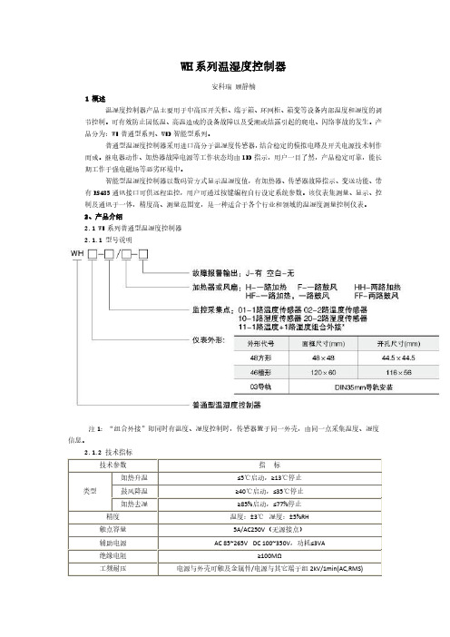
安科瑞 顾静楠 1 概述
温湿度控制器产品主要用于中高压开关柜、端子箱、环网柜、箱变等设备内部温度和湿度的调 节控制。可有效防止因低温、高温造成的设备故障以及受潮或结露引起的爬电、闪络事故的发生。产 品分为:WH 普通型系列、WHD 智能型系列。
普通型温湿度控制器采用进口高分子温湿度传感器,结合稳定的模拟电路及开关电源技术制作 而成。继电器动作、加热器故障电源等工作状态均由 LED 指示,用户一目了然,产品稳定可靠,能长 期工作于强电磁场等恶劣环境中。
2 路温湿度控制 3 路温湿度控制
2. 变送输出 3. RS485 通讯
选功能
WH-2/2 WH-2/3
注:1、每一路传感器对应二组控制输出接点(无源),分别接加热器和风扇; 加热器用于升温或去湿,风扇用于降温;
2、传感器与控制器之间的连接线长度最大不得超过 20 米。 2.2.4 外形及尺寸(单位:mm)
智能型温湿度控制器以数码管方式显示温湿度值,有加热器、传感器故障指示、变送功能、带 有 RS485 通讯接口可供远程监控,用户可通过按键编程自行设定系统参数。该仪表集测量、显示、控 制及通讯于一体,精度高、测量范围宽,是一种适合于各个行业和领域的温湿度测量控制仪表。 2、产品介绍 2.1 WH 系列普通型温湿度控制器 2.1.1 型号说明
注 1:仪表端子 30、31、32 为可选功能输出端:故障报警、通讯、变送输出三者其一。
3、传感器
3.1 概述 WH 系列普通型温湿度控制器及 WHD 智能型温湿度控制器的传感器均使用外接方式。传感器部
分采用专用外壳,通风效果好,外观精致,既能有效保护内部元件,提高使用寿命,又方便安装、接
线。 3.2 型号说明
●WHD48/72/96 温湿度控制器
10种传感器资料
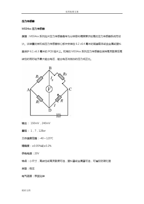
压力传感器MS54xx压力传感器原理:MS54xx系列贴片压力传感器是专为分辨率和精度要求较高的压力传感器系统而设计。
该装置的微机械压力传感器核心部件安装在6.2 x6.4毫米的陶瓷载体或由金属或塑料盖保护6.1 x6.3毫米的PCB硅片上。
现有的MS54xx系列压力传感器在保持高灵敏度后高线性的同时给予最大输出电压,输出电压与施加的压力成正比。
输出:150mV,240mV量程:1,7,12Bar工作温度范围:-40~125℃精确度:±0.05%或±0.2%供电电源:20V特点:小尺寸,高线性或高灵敏度可选,塑料罩或金属罩可选,可灌胶防潮处理类型:绝压电气连接:表面贴装典型应用:绝压测量系统,发动机控制,高分辨率高度计,气压测量计,防水手表,水下计算机,轮胎压力监测系统,医疗器械,充气泵控加速度传感器7114A加速度传感器工作原理是:敏感元件将测点的加速度信号转换为相应的电信号,进入前置放大电路,经过信号调理电路改善信号的信噪比,再进行模数转换得到数字信号,最后送入计算机,计算机再进行数据存储和显示。
当传感元件以加速度a运动时,质量块受到一个与加速度方向相反的惯性力作用,发生与加速度成正比a的形变,使悬臂梁也随之产生应力和应变。
该变形被粘贴在悬臂梁上的扩散电阻感受到。
根据硅的压阻效应,扩散电阻的阻值发生与应变成正比的变化,将这个电阻作为电桥的一个桥臂,通过测量电桥输出电压的变化可以完成对加速度的测量输出:±5V量程:±10g、±50g、±500g封装:不锈钢工作温度范围:-55°C~125°C供电电源:10~30Vdc特点:±10g ~±500g动态量程、带宽可达15kHz、密封焊接、环形剪切、稳定的温度响应、TEDS选项类型:压电IEPE电气连接:电缆典型应用:振动及冲击监测、实验室测试、模型应用、高频应用湿敏传感器HTF3226LF湿敏传感器原理:湿敏电阻的特点是在基片上覆盖一层用感湿材料制成的膜,当空气中的水蒸气吸附在感湿膜上时,元件的电阻率和电阻值都发生变化,利用这一特性即可测量湿度。
第13章 集成传感器
第13章 集成化智能传感器 传感与检测技术
13.2.1 基于1-WIRE总线的DS18B20型智能温度传感器
DS1820是DALLAS半导体公司生产 的可组网数字式温度传感器
与其它温度传感器相比有以下特点:
• 单线接口方式,可实现双向通讯;
7.智能传感器的主要产品 智能传感器的分类方法与第1章中传统传感器的分类方法基本 相同,可按照传感器的物理量分类;传感器的工作原理分类; 传感器的信号输出的性质分类。
第13章 集成化智能传感器 传感与检测技术
13.2 单片智能温度传感器
智能型温度传感器、温控器是将 A/D 转换电路,ROM存
储器集成在一个芯片上,广泛应用于自动控制系统。
可在I/O线连接其它驱动。可同时在一根总线上进行8个温 度通道的测量。
第13章 集成化智能传感器 传感与检测技术
DS18B20操作指令ቤተ መጻሕፍቲ ባይዱ
18B20内部自带5个ROM指令、6条专用指令:
ROM指令; Read ROM(33h), 读ROM Match ROM(55h), 比较 Skip ROM(CCh), 跳过ROM Search ROM(F0h), 搜索、查找 Alarm ROM(ECh), 报警
• 支持多点组网功能,多个18B20可并联 在唯一的总线上实现多点测温;
• 内部有唯一序列号; • 使用中不需要任何外围器件; • 测量结果以9位数字量方式串行传送; • 温度范围 -55~+125 ℃; • 供电电压 +3 ~+5.5V。
123
GND I/O VDD
DB18B20引脚、封装
两种封装形式; I/O :输入/输出端 VDD :外部电源+5V GND :地; NC :空脚
温湿度传感器使用说明书
NO:S1*******使用说明书温湿度传感器目录1、产品介绍 (1)1.1概述 (1)1.2功能特点 (1)1.3外观尺寸 (1)2、性能参数 (2)3、使用方法 (4)3.1系统框架图 (4)3.2安装说明 (6)4、通信协议 (9)4.1通讯基本参数 (9)4.2数据帧格式定义 (9)4.3通讯基本参数 (11)4.4通讯协议示例以及解释 (12)5、常见问题及解决方法 (14)6、保养维护 (15)7、运输存储 (16)7.1运输要求 (16)7.2存储要求 (16)8、订货服务 (17)8.1订货方法 (17)8.2客户服务 (17)1产品介绍1.1概述本(系列)产品可在线监测环境温度和湿度信息,广泛用于开关柜仪表室、断路器室、电缆室等处的环境温湿度在线监测。
采用进口工业级微处理器芯片、进口高精度温度传感器,确保产品高精度和可靠性。
1.2功能特点◆进口的测量单元,测量精准。
◆专用的485电路,通信稳定。
◆宽电压范围供电,安装方便。
1.3外观尺寸(单位:mm公差:±0.5)2性能参数3使用方法3.1系统框架图本产品也可以多个传感器组合在一条485总线使用,理论上一条总线可以接254个485传感器,另一端接入带有485接口的PLC 、通过485接口芯片连接单片机,或者使用USB转485即可与电脑连接,使用我公司提供的传感器配置工具进行配置和测试(在使用该配置软件时只能接一台设备)。
3.2安装说明3.2.1注意事项1、传感器应尽量垂直放置,保证安装墙面时,温湿度探头在传感器本体的下方(传感器本体上的字体为正方向)。
2、安装高度为人体坐高或主要测量的环境区域。
3、避免在易于传热且会直接造成与待测区域产生温差的地带安装,否则会造成温湿度测量不准确。
4、安装在环境稳定的区域,避免直接光照,远离窗口及空调、暖气等设备,避免直对窗口、房门。
5、尽量远离大功率干扰设备,以免造成测量不准确,如变频器/电机等。
LH-TH20系列温湿度传感器说明书 (2)

温湿度传感器说明书适用型号:LH-TH20系列修订记录:目录1. 产品介绍 (2)2. 规格参数 (2)3. 产品尺寸 (3)4. 485通信协议与数据格式 (3)4.1. 通讯基本参数 (3)4.2. 数据帧格式定义 (4)4.3. 寄存器地址 (4)4.4. 参数读取 (6)5. 模拟量协议 (7)6. 电气接线 (8)7. 售后服务 (8)7.1. 售后服务承诺 (8)7.2. 免责声明 (8)7.3. 联系方式 (9)LH-TH20系列温湿度传感器广泛适用于农业大棚/花卉培养等需要温湿度监测的场合。
传感器内输入电源,感应探头,信号输出三部分完全隔离。
安全可靠,外观美观,安装方便。
2.规格参数图3.1 4.485通信协议与数据格式4.1.通讯基本参数4.2.数据帧格式定义采用 Modbus-RTU 通询规约,格式如下:地址码= 1字节功能码= 1字节数据区= N字节错误校验= 16位 CRC 码结束结构>=4字节的时间地址码:为设备的地址,在通询网络中是唯一的。
功能码:主机所发指令功能提示。
数据区:数据区是具体通询数区,注意 16bits 数据高字节在前。
CRC码:二字节的校验码。
4.3.寄存器地址湿度校准说明:有符号数(有正负)偏移值的 10 倍,比如目前读出的湿度值为 23.8 ,如果我们设置这个湿度偏移值为-28,那么设置完后读出的湿度值为:23.8-2.8=21.0%RH 温度校准说明:有符号数(有正负),偏移值的 10 倍,比如目前读出的温度值为 23.8 度,如果我们设置这个温度偏移值为-28,那么设置完后读出的温度值为:23.8-2.8=21.0℃(特别注意:PLC 中需要将地址码加 1,如果 03 功能码读取 1 号寄存器,需要写入 40002)4.4.参数读取(1)例:读取设备地址为01的传感器温湿度注释:将返回的十六进制数据转换成十进制除以10,即可得到相应的温湿度值。
无线温湿度传感器技术说明书

无线温湿度传感器一、产品型号:EN-TH600EN-TH600温湿度数据采集模块是一款高性能温湿度数据采集传输模块,可选的RS485/无线不同输出,MODBUS工业控制总线协议,可以多个模块共同接入总线组网,也可以与其他符合MODBUS协议的设备共同组网,实时、稳定地监控多个生产现场环境变化,以使用户准确把握不同应用现场的环境变化,快速做出反应,保障生产现场环境的稳定性。
二、功能特点DATA/VCC/GND/RXD(RS85-A)/TXD(RS485-B)五线接口及无线两种方式,简单可靠,便于扩展;可选的RS232/RS485/TTL信号传输、无线传输方式;基于MODBUS工业控制总线协议的数据传输,性能可靠,兼容性好,易于组网;支持简单字符指令,便于单个模块简易应用场合使用体积小巧,易于安装;针对恶劣环境做防潮处理,适用于工矿企业、农牧行业大棚等潮湿环境;三、参数配置:无线频率:470MHz通讯距离:2km串口波特率:1200 / 4800 / 9600 / 19200 / 38400 / 57600 ;数据位:8位,不可配置;校验:无校验 / 奇校验 / 偶校验;停止位:1 /2 位;配置完成后断电并重新通电后配置生效;四、产品特性测量温度范围:-40℃~+80℃;分辨率:0.1℃;精度±0.5℃工作温度范围:-40℃~+80℃;测量湿度范围:0%~100%(RH)相对湿度;分辨率:0.1%RH;精度:环境温度25℃下±2%RH;工作湿度范围:0%~100%(RH)相对湿度;电源:3.6V锂电;支持数据格式:串行MODBUS协议,简易ASCII码字符指令:“READ”,“AUTO”,“STOP”;模块ID可配置,范围为:1~255;技术参数测量范围温度:-40-80℃湿度:0-99.9%RH精度:(25℃环境下) 温度:typ±0.5℃ max±1℃湿度:±2%RH(10...90%RH)分辨率:温度:0.1℃湿度:0.1%RH衷减值:温度:<0.1℃/年湿度:<0.5%RH/年硬件参数温度:电阻式传感器湿度:电容式传感器上传数据频率:次/15min电源:3.6V 锂电长*宽*高:126*96*30(mm)外壳材料:PC塑料+铝合金边框产品类别100版本为RS485 600版本为LORA无线出厂设置串行接口:波特率:9600,数据位8位,停止位1位模块ID(“0X**”表示十六进制数):0X11。
无线温湿度传感器测量模块设计答辩稿

温湿度的测量在工业和农业生产中具有重要的 意义。利用单片机对温湿度进行监测精度高,功能 强,体积小,价格低,简单灵活等优点,再利用无 线技术进行数据传输,能有效的避免复杂的布线和 空气的腐蚀,增强测量系统的准确性和可靠性。
本设计主要的内容是用C8051F340单片机程序 控制,利用DHT11数字式温湿度传感器采集温湿度 数据,利用CC1101无线收发模块实现温湿度数据的 无线传输,最后利用LCD1602将温湿度进行显示。 测量简便、灵敏度高、易于安装。
LCD1602显示温 湿度值
单片机
无线 发 模块
DHT11进行温湿 度采集
无线接收模 块
单片机
温湿度显示
主程序流程图
- 1、下载文档前请自行甄别文档内容的完整性,平台不提供额外的编辑、内容补充、找答案等附加服务。
- 2、"仅部分预览"的文档,不可在线预览部分如存在完整性等问题,可反馈申请退款(可完整预览的文档不适用该条件!)。
- 3、如文档侵犯您的权益,请联系客服反馈,我们会尽快为您处理(人工客服工作时间:9:00-18:30)。
HTF3226LF相对湿度测量模块
使用HS1101LF湿敏电容硬质封装的湿度传感器HTF3226LF是专门适用于需要精确可靠检测湿度的OEM用户,它的特点是有很小的易于安装的接头。
由于它是线性的频率输出湿度检测模块,因此可以直接与微处理器相接。
一、检测原理
基于独特的湿度感应晶片,随着环境湿度值的变化有着稳定的容值变化的湿敏电容为基本检测元件,搭配典型的555时基电路,经过校准之后做成线性的频率输出的湿度检测模块HTF3226LF。
二、主要性能特征
·尺寸与接头与现有的湿度模块相匹配
·10~95%RH稳定比例线性的频率输出
·标定+/-5%RH@55%RH
·可选的10K+/-3%NTC温度传感器
·好的温度特性
·高可靠性与长时间稳定性
三、传感器特点
·在长时间处于饱和状态后快速脱湿
·响应时间快
·对化学品的高抵抗性
·浸水没有影响
·专利的固态聚合物结构
四、最大参数(Ta=25℃除非特别注明)
特性参数(Ta=25℃,Vs=5.0VDC除非特别注明)
HTF3223的相对湿度精度曲线
传感器的湿度典型输出:
五、温度传感器特性(Ta=25℃)
典型温度输出:
取决于这个需要测量的温度范围和相关的精度,我们建议两种方法去获取NTC的阻抗值。
RT:温度T时的NTC的电阻值T–温度(以K表示)R—电阻值(以Ω表示)
RN:在额定温度T时的NTC的电阻值
T,TN:温度以K表示
β:Beta值,NTC材料的特殊常数(以K表示)
e:以e为底的自然对数(e=2.71828)
①一个NTC热敏电阻的独有特性是可以,然而只是通过指数关系粗略的测量温度,作为材料参数β在实际中也是取决于应用温度的。
所以这一近似值是适合于去描述一个有限的范围(粗略测量额定温度或者是精确的阻值)
②对于在实际应用中,一个更真实的R/T关系曲线精度描述可能是必要的。
使用更复杂的方法(例如:同样的Steinhart-Hart方程)或者是R/T关系式如下表所给出的,下表已经用实验的方法确定温度增量的极限精度。
温度输出查表:
六、出厂检验
HTF3226LF在出厂前已经通过了HUMIREL的一系列检验,其中包括震动、颤动、存储、高温、高湿及静电。
可抵抗一些化学物质的例如盐雾SO2(0.5%)、H2S(0.5%)、NO、CO、CO2、软化剂、肥皂、甲苯、酸(H2SO4,HNO3,HCI)、HMDS、杀虫剂、香烟等等。
七、封装尺寸
声明:
本手册是根据Humirel的HTF3226LF英文原版datasheet翻译而来,本司(深圳市新世联科技有限公司郑星辉1-8-9-0-2-4-5-7-1-9-0)所做编译只是为了促进该产品在中国地区的销售及应用,如果用户在阅读过程中遇到任何问题,请参考原始英文文件。