stego ETR 011
Stearns 1-056-X00 系列螺纹钢带刹车产品说明书

Installation and Service Instructions for 1-056-X00* Series (all revisions)Manual Adjust BrakesTypical NameplateImportantPlease read these instructions carefully before installing, operating, or servicing your Stearns Brake. Failure to comply with these instructions could cause injury to personnel and/or damage to property if the brake is installed or operated incorrectly. For definition of limited warranty/lia-bility, contact Rexnord Industries, LLC, Stearns Division, 5150 S. International Dr., Cudahy, WI 53110, (414) 272-1100.CautionInstallation and servicing must be made1. in compliance with all local safety codes including Occupational Safety and Health Act (OSHA). All wiring and electrical con-nections must comply with the National Electric Code (NEC) and local electric codes in e of this brake in atmospheres contain-2. ing explosive gases and dusts must be in accordance with NEC article 501. this brake is not suitable for use in certain atmospheres containing explosive gases and dusts. HazLoc inspection authorities are responsible for verifying and authorizingthe use of suitable designed and installed HazLoc equipment. When questions arise consult local A uthority H aving J urisdiction (AHJ).To prevent an electrical hazard, disconnect3. power source before working on the brake. If power disconnect point is out of sight, lock disconnect in the off position and tag to prevent accidental application of power.Make certain power source conforms to4. the requirements specified on the brake nameplate.Be careful when touching the exterior of an5. operating brake. Allow sufficient time for brake to cool before disassembly. Surfaces may be hot enough to be painful or cause injury.Do not operate brake with housing6. removed. All moving parts should be guarded.Installation and servicing should be per-7. formed only by qualified personnel familiar with the construction and operation of the brake.For proper performance and operation, only 8. genuine Stearns parts should be used for repairs and replacements.After usage, the brake interior will contain9. burnt and degraded friction material dust.This dust must be removed before servic-ing or adjusting the brake.DO NOT BLOW OFF DUST using an airhose. It is important to avoiddispersing dust into the air or inhaling it, as this may be dangerous to your health.a) Wear a filtered mask or a respirator while removing dust from the inside of a brake.b) Use a vacuum cleaner or a soft brush to remove dust from the brake. When brush-ing, avoid causing the dust to become air-borne. Collect the dust in a container, such as a bag, which can be sealed off.10. Caution! While the brake is equipped witha manual release to allow manual shaft rotation, the motor should not be run with the manual release engaged, to avoid over-heating the friction disc(s).General DescriptionThese series of brakes are spring-set, elec-trically released. They contain one or more rotating friction discs (4) driven by a hub (16) mounted on the motor or other shaft.Note: Fan-guard mounted brakes requiring IP54 & IP55 protection may require additional sealing measures beyond seals provided with this brake. Pressurized sprays aimed at the fan and brake hub surfaces can result in fluid migration along the motor shaft and keyway, and into the brake. The use of an appropri-ate sealant such as RTV or a forsheda seal is advised.Operating PrincipleThese series contain one or more friction discs (4) assembled alternately between the endplate (2) friction surface, stationary disc(s) (3) and pressure plate (also called stationary disc) (3). The stationary disc(s) are restrained from rotat-ing by being keyed into the endplate. With the brake released, all disc pack components are free to slide axially and the friction disc(s) to rotate.Brake release occurs when the solenoid coil is electrically energized, causing the solenoid plunger to travel a specified distance and through a lever system, overcoming the pres-sure spring force. This action releases the clamping force on the disc pack, thereby allow-ing the friction disc(s) and brake hub to rotate.Brake sets and torque is produced when electric current to the solenoid coil is interrupted, there-by collapsing the solenoid magnetic field. Thesolenoid plunger returns to its original de-ener-gized position allowing the lever arm to move forward by virtue of the compressed torquesprings. This action compresses the disc pack components which applies a retarding torque to the brake hub and ultimately restores the brake to a spring-set static condition.*T his sheet includes Series 1-056,000; 1-056,100; 1-056,200; 1-056,300; 1-056,400; 1-056,500; 1-056,600 and 1-056,900. For other series consult factory.1-056-1001-056-6001-056-2001-056-9001-056-300For replacement parts refer to sheets: Series Sheet Part No.1-056-000 8-078-906-001-056-100 8-078-906-011-056-200 8-078-906-021-056-300 8-078-906-031-056-400 8-078-906-041-056-500 8-078-906-051-056-600 8-078-906-061-056-900 8-078-906-09Also available at Position hub on shaft as shown.Place hub on motor shaft.Tighten set screws to motor shaft.Remove brake housing.Housings vary by series number.See page 1.AC coils are 50/60 Hz, single phase rated. Power supply to coil must not have current or frequency limiting output that is less then the coil requirement.- Connect leadwires to power source. Verify voltage rating* per nametag on coil.- Keep wiring away from pinch points and moving components.Slide endplate over hub noting position of stabilizer clips, if used. (Refer to Friction DiscReplacement, view 3 and 3A.) Tighten mounting screws.counter-clockwise* F or DC voltages see sheet 8-078-950-00..188” (4.77mm)BRAKE MOUNTING (Manual Adjust) 1-056-X00* F or vertical assembly of 20 & 25lb-ft brakes, refer to page 3.clockwiseReplace brake housing and tighten to torque specified below: FRICTION DISC REPLACEMENT SERIES 1-056-X002Remove support plate screws and lift support from brakeInstall new friction disc(s) and stationary disc(s) as shown.Remove and discard old friction disc.counter-clockwiseBrake series Torque 1-056-000 1-056-3001-056-400 1-056-5008 lb-in1-056-100 1-056-2001-056-600 1-056-90012 lb-inReposition support plate on endplate and tighten mounting screws to 55 lb-in.clockwiseNote: Stabilizer clips should never be located over the set screws of the hub.Single disc brakes always use two stabilizer clips, locate at 90° from each other.Double disc brakes typically will not require stabilizer clips, how-ever there are some special modifications that will use them.Rev A & B may have these clips may have these clips located 1 per disc, and should never be positioned in line with each other.Rev C will have only one clip, used on the inner-most disc. No clip will be used on the outer-most disc.Three disc brakes will never use stabilizer clips on friction discs.Note : Friction discs can wear to 1/2 their original thicknes, or .093”Lift plunger/solenoid lever assembly out of coil.Remove plunger guide.A) Re-insert plunger into coil; drop pivot pin into cradle of support plate.B) Remove screwdriver.A) Insert new coil. (Lead wires in same position as old coil.)B) Insert plunger guide.Insert screwdriver between support plate and lever arm and pry forward.ABABRemove housing and disconnect power and wiring to coil.Discard coil.Vertical Brake AssemblySingle disc brakes are universal mount and do not require separator springs. Double disc brakes are universal mount but require separator springs which are preassembled to the stationary disc. These discs are inserted spring first into the brake. Refer to figure 5A below.Installation Procedure for 20 and 25 lb-ft brakes if mounted vertical to motor shaft (These brakes arefactory assembled for horizontal operation.)Remove support plate by loosening the three mounting screws.Remove stationary discs and friction ing the spring kit provided with thisbrake, insert three springs of identical color into each stationary disc hole. Springs are inserted from the side opposite the indent mark (see Figure 5B). Stationary disc should be placed on a clean flat surface with a clearance hole to allow the tip of the spring to extend through the bottom side of the stationary plate. Using the 1/8” pin Mount support plate and torque screws evenly to 55 lb-in.Reconnect coil and replace housing per installation instructions, page 2.3COIL REPLACEMENT SERIES 1-056-X003/16 hex wrenchclockwiseAIR GAP ADJUSTMENT 1-056-X00VERTICAL SPRING ASSEMBLY 1-056-X00Figure 5BFigure 5CFigure 5A3/16 hex wrench, or flat screwdriver on older models.Min/Max.38” - .69”.45” - .69”.50” - .69”56,X00 Series Air Gap (REV A & B)Min/Max .45” - .69”.50” - .69”56,X00 Series Air Gap (REV C)Maximum gap should not exceed .69”3/16 hex wrenchcounter-clockwise111110 10Figure 6COIL FAILURESUPPLY VOLTAGE CORRECTIONReduce voltage or replace withReplace rectifier or replace withIncrease current rating of powerWIRING CORRECTIONEXCESSIVE WEAR / OVERHEATING AIR GAP CAUSELow solenoid air gapDisc pack draggingCYCLE RATE CAUSEBrake “jogging” exceeding coilcycle rateTROUBLESHOOTINGRexnord Industries, LLC, Stearns Division, 5150 S. International Dr., Cudahy, WI 53110, (414) 272-1100 Fax: (414) 277-4364 TORQUE ADJUSTMENT。
ams-OSRAM AG 自动干燥包装过程介绍说明书

Published by ams-OSRAM AGTobelbader Strasse 30, 8141 Premstaetten, Austria Phone +43 3136 500-0 © All rights reservedInfonoteAO-IN-2022-007-IIntroduction of automated dry packing process for productsprovided in reels with 180mm and 330mm sizeAO-IN-2022-007-I2 | Version no.3 (2022-03-25)04.04.2022Dear Customer,please take note of this Infonote.This customer notification is for information only and does not require customer approval.Objective: Introduction of automated dry packing process for products providedin reels with 180mm and 330mm sizeAffected products: Products provided in reels with 180mm and 330mm sizeReason for change: Industrialization and standardization of existing packing processDescription of change: Current statusManual packing processNew statusAutomated packing process For details refer to file 2_cip_AO-IN-2022-007-ITime schedule: Introduction of automated dry packing processearliest from 18.04.2022 (will be implemented as soon as ready)Assessment: No change in fit, form, function and reliability of the affected productsDocumentation: Customer information package: 2_cip_AO-IN-2022-007-IPublished by ams-OSRAM AGTobelbader Strasse 30, 8141 Premstaetten, AustriaPhone +43 3136 500-0 © All rights reserved1Sensing is lifeConfidentialOSR OS Q CQM AM 2022-04-04InfonoteAO-IN-2022-007-IIntroduction of automated dry packing process for products provided in 180mm and 330mm size reelsCustomer information packageAgendaConfidential Page1.Reason for change32.Description of change43.List of affected products54.Time schedule6232022-04-04 | Infonote | AO-IN-2022-007-I | Customer information packagefor products provided in 180mm and 330mm size reelsReason for changeConfidentialItemDescriptionIntroduction of automated dry packing processIndustrialization and standardization of existing packing processDescription of changefor products provided in 180mm and 330mm size reels Item Current status New statusIntroduction of automated dry packing process -Manual process-MBB with grooved sealing-Automated process-MBB with plane sealing42022-04-04 | Infonote | AO-IN-2022-007-I| Customer information package Confidential52022-04-04 | Infonote | AO-IN-2022-007-I | Customer information packageList of affected productsConfidentialfor products provided in 180mm and 330mm size reelsMultiple Brands affectedProducts provided in 180mm size reels Products provided in 330mm size reels62022-04-04 | Infonote | AO-IN-2022-007-I | Customer information packageTime scheduleConfidentialTime scheduleIntended Start of Introduction 18.04.2022 (earliest, will be implemented as soon as ready)for products provided in 180mm and 330mm size reelsSensing is life。
意法半导体推出业界首款可同时支持用户接口和手抖补偿功能的角速度传感器

意法半导体推出业界首款可同时支持用户接口和手抖补偿功能
的角速度传感器
佚名
【期刊名称】《《传感器世界》》
【年(卷),期】2012(018)001
【摘要】意法半导体(STMieroelectronics)最新推出了一款数字输出3轴角速度(陀螺仪)传感器L3G41S,可同时支持用户接口功能和手抖补偿功能。
新产品只配备了一个MEMS三轴角速度传感器,通过相关信号电路,可同时支持用户接口功能和手抖补偿功能。
【总页数】1页(P34-34)
【正文语种】中文
【中图分类】TP212
【相关文献】
1.意法半导体(ST)推出世界首款基于 ARM Cortex-M7的STM32 F7系列微控制器 [J],
2.意法半导体(ST)推出世界首款3轴汽车陀螺仪 [J],
3.意法半导体(ST)与FIME携手推出业界首款兼容全球支付标准的Calypso交通卡 [J],
4.意法半导体推出世界首款3轴汽车陀螺仪 [J],
5.意法半导体(ST)推出业界首款高符号率卫星解调器,实现更快速、更经济的宽带服[J],
因版权原因,仅展示原文概要,查看原文内容请购买。
施密特热电风速仪VT110-VT115使用手册说明书

Hotwire thermo-anemometerVT110 - VT115 DESCRIPTION OF THE DEVICEBacklight keyHold/min/max keySelect keyOn/Off/Esc keyOK keyAirflow directionRed point :landmarkProtective tube of thesensitive element (1)Sensitive element (velocity)Sensitive element(temperature)Bottom of thehotwire probeAirflow directionWhite point :landmarkTube de protection del'élément sensible (1)Sensitive element (velocity)Sensitive element(temperature)Bottom of the telescopichotwire probe➢Turn on the device by pressing on « On/Off/Esc ».The device displays its name « VT110 » or « VT115 » then the measured values.➢Put the probe to the required location.The device displays the measurements of velocity or airflow and of temperature.PERFORM A MEASUREMENTVT110 : Standard hotwire probe VT115 : Telescopic hotwire probe●Before any device usage with the standard or telescopic hotwire probe standard, please lower the protective tube (1)of the sensitive element.●Always use the hotwire probe with the red point in front of the flow.●Always use the telescopic hotwire probe with the white point in front of the flow.MEASURE AND DISPLA Y THE AIRFLOWIt's possible to measure and display the airflow in place of the velocity.The device is on and displays the velocity and temperature measurements.➢Press on « Select ».« MODE » blinks.➢Press on « OK », the mode currently used blinks at the bottom of the screen.➢Press on « Select » to select the « FLOW » mode.➢Press on « OK ».➢« CONE » blinks on screen, press on « Select » to make appear « RECT », then « CIRC ».➢Press on « OK » to select « RECT » or « CIRC » according to the type of sheath or cone « CONE » for a measurement with an airflowcone.●If « RECT » or « CIRC » is selected, the measuring unit of the type of sheath displays.➢Press on « Select » to select the unit : mm or inch then press on OK to adjust the section size : ●If the type of selected sheath is circular : « DIAM » displays and the first digit blinks.Press on « Select » to select its value then press on « OK » to validate. Perform the same procedure to select the value of the following digits (to return to the previous digit press on « On/Off/Esc »). When the last digit is adjusted, press on « OK » to validate . The device returns to the display of airflow and temperature measurements.●If the type of selected sheath is rectangular : « LENGT » displays and the first digit blinks.●Press on « Select » to select its value then press on « OK » to validate. Perform the same procedure to select the value of the following digits (to return to the previous digit press on « On/Off/Esc »). When the last digit is adjusted, press on « OK ». « WIDTH » to adjust the width also displays on screen, perform the same procedure to select the digits value, when the last digit is adjusted, press on « OK » to validate. The device returns to the display of airflow and temperature measurements.●If « CONE » is selected: « CONE » displays on screen and the type of cone blinks : K35, K75, K120, K150.➢Press on « Select » to select the type de cone, then press on « OK » to validate. The device returns to the display of airflow and temperature measurements.The length, the width and the diameter of the section are adjustable from 1 to 3000 mm.FREEZE THE MEASUREMENTDuring a measurement :➢Press on « Hold/min/max » to freeze the measurement.« Hold » displays on screen and the measurements of velocity or airflow and of temperature are frozen.➢Press on « On/Off/Esc » to return to the measurements display.DISPLA Y THE MINIMUM AND THE MAXIMUMOnce the measurement is frozen :➢Press on « Hold/min/max » :The device displays the maximum value of velocity or airflow measured since the last questioning at the top of the screen and the minimum value of velocity or airflow measured since the last questioning at the bottom of the screen.➢Press on « Hold/min/max » :The device displays the maximum value of temperature measured since the last questioning at the top of the screen and the minimum value of temperature since the last questioning at the bottom of the screen.➢Press on « On/Off/Esc » to return to the measurements display..PERFORM AN A VERAGE IN VELOCITYDuring a measurement :➢Press on « OK », « Start » displays on screen.➢Press again on « OK », the average calculation is launched, « End » displays on screen and « AVG » blinks.➢Press on « OK » to end the average calculation, the average displays.➢Press again on « OK » to display the maximum and minimum values measured during the average calculation.➢Press on « On/Off/Esc » to exit the average function and return to the measurements display.Select the measuring unit in airflow :The device is on and in airflow mode.➢Press on « Select » until « UNIT » blinks on screen with the airflow unit displayed below.➢Press on « OK ».The unit currently used blinks on screen.➢Press on « Select » to select the required measuring unit : m 3/h, L/s, fcm or m 3/s. ➢Press on « OK » to validate.« UNIT » blinks on screen.➢Press on « On/Off/Esc » to return to the measurement display.Select the measuring unit in temperature :The device is on and displays the measurements.➢Press on « Select » until « UNIT » blinks on screen with the temperature unit displayed below.➢Press on « OK ».The unit currently used blinks on screen .➢Press on « Select » pour choisir l'unité de mesure souhaitée : °C, °F.➢Appuyer sur la touche « OK » pour valider.« UNITE » clignote à l'écran.➢Appuyer sur la touche « On/Off/Esc » pour revenir à la mesure.Select the measuring unit in velocity :The device is on and in velocity mode.➢Press on « Select ».« MODE » blinks on screen.➢Press again on « Select ».« UNIT » blinks on screen.➢Press on « OK », the measuring unit currently used blinks at the bottom of the screen, then press on « Select » to select therequired measuring unit : fpm, km/h, m/s.➢Press on « OK » to validate.« UNIT » blinks on screen.➢Press on « On/Off/Esc » to return to the measurement display .ADJUST THE DEVICE●Device drop-down menuSEL.P_ATM 1009 hPa1xSelect5xSelectSelectSelectSEL.UNIT Km/hSEL.AUTO OFF OFF3x4x2xSEL.UNIT °CSEL.MODE VITSelectSEL.UNIT °COKUNIT SEL.°CSEL.UNIT °F0,00m/s 77,3°COKSelectUNIT SEL.°C ou °FOn/Off/Esc0,00m/s 25,4°COKOn/Off/EscUNIT SEL.Km/hUNIT SEL.Km/h, m/s...OKSelectSEL.UNIT Km/hSEL.UNIT m/sUNIT SEL.m3/h, L/s...OKSEL.UNIT L/sOn/Off/EscUNIT SEL.m3/hL/s 25,4°COKSEL.UNIT m3/hSelect➢Remove the front part at the back of the device.➢Change the old batterers by AAA LR03 1.5 V batteries.➢Replace the front.CHANGE THE BA TTERIESThe device is on and displays the measurements.➢Press on « Backlight » : to activate the device backlight.➢To deactivate the backlight press again on « Backlight ».Activate or deactivate the keys beep :The device is on and displays the measurements.➢Press on « Select » until « BEEP » blinsk on screen.➢Press on « OK ».« OFF » or « ON » blinks on screen.➢Press on « Select » to activate the keys beep « ON » or deactivate the keys beep « OFF ».➢Press on « OK » to validate.➢Press on« On/Off/Esc » to return to the measurement display.Adjust the auto shut-off :The device is on and displays the measurements.➢Press on « Select » until « AUTO OFF » blinks on screen.➢Press on « OK ».The time before device auto shut-off blinks on screen.➢Press on « Select » to select the time before device auto shut-off : 15, 30, 45, 60, 75, 90, 105, 120 minutes or OFF.➢Press on « OK » to validate.➢Press on « On/Off/Esc » to return to the measurement display.AUTOOFFOFFSelectSEL.AUTOOFF30mnSEL.AUTOOFFOFFAUTOOFF15, 30mn...On/Off/Esc0,00m/s25,4°COKOKACTIV A TE THE BACKLIGHTSEL.BEEPONBEEPSEL.ONSEL.BEEPOFFBEEPSEL.OFF / ONOKOK On/Off/EscSelect0,00m/s25,4°C Once returned to KIMO, required waste collection will be assured in the respect of the environment in accordance to 2002/96/CE guidelines relating to WEEENTang–portable-VT11-VT115–1/6/14–RCS(24)Périgueux34928295Non-contractualdocument–Wereservetherighttomodifythecharacteristicsofourproductswithoutpriornotice.。
Omega TX801TC系列热感应传感器产品指南说明书

An OMEGA Technologies CompanyU s e r 's G u i d ee-mail:**************TX801TC SERIESTHERMOCOUPLE TRANSMITTERWhere Do I .ind Everything I Need for Process Measurement and Control?OMEGA...Of Course!TEMPERATUREThermocouple, RTD & Thermistor Probes, Connectors, Panels & Assemblies Wire: Thermocouple, RTD & Thermistor Calibrators & Ice Point ReferencesRecorders, Controllers & Process Monitors Infrared PyrometersPRESSURE, STRAIN AND .ORCE Transducers & Strain Gauges Load Cells & Pressure Gauges Displacement Transducers Instrumentation & Accessories.LOW/LEVELRotameters, Gas Mass Flowmeters & Flow Computers Air Velocity IndicatorsTurbine / Paddlesheel Systems Totalizers & Batch ControllerspH/CONDUCTIVITYpH Electrodes, Testers & Accessories Benchtop/Laboratory MetersControllers, Calibrators, Simulators & Pumps Industrial pH & Conductivity Equipment DATA ACQUISITIONData Acquisition & Engineering Software Communications-Based Acquisition Systems Plug-in Cards for Apple, IBM & Compatibles Datalogging SystemsRecorders, Printers & Plotters HEATERS Heating CableCartridge & Strip Heaters Immersion & Band Heaters Flexible Heaters Laboratory HeatersENVIRONMENTALMONITORING AND CONTROL Metering & Control Instrumentation Refractometers Pumps & TubingAir, Soil & Water MonitorsIndustrial Water & Wastewater TreatmentpH, Conductivity & Dissolved Oxygen InstrumentsM-3802/0302✔✔✔✔✔✔✔✔✔✔✔✔✔✔✔✔✔✔✔✔✔✔✔✔✔✔✔✔✔✔✔✔✔OMEGAOMEGAnet SM On-Line Service Internet e-mail **************Servicing North America:USA:One Omega Drive, Box 4047ISO 9001 Certified Stamford, CT 06907-0047Tel: (203) 359-1660FAX: (203) 359-7700e-mail:**************Canada:976 BergarLaval (Quebec) H7L 5A1Tel: (514) 856-6928FAX: (514) 856-6886e-mail:****************.or immediate technical or application assistance: USA and Canada:Sales Service: 1-800-826-6342 / 1-800-TC-OMEGA SMCustomer Service: 1-800-622-2378 / 1-800-622-BEST SMEngineering Service: 1-800-872-9436 / 1-800-USA-WHEN SMTELEX: 996404 EASYLINK: 62968934 CABLE: OMEGA Mexico andLatin America:Tel: (95) 800-TC-OMEGA SM FAX: (95) 203-359-7807En Espanol: (203) 359-7803e-mail:*****************Servicing Europe:Benelux:Postbus 8034, 1180 LA Amstelveen, The NetherlandsTel: (31) 20 6418405FAX: (31) 20 6434643Toll Free in Benelux: 06 0993344e-mail:************Czech Republic:ul. Rude armady 1868, 733 01 Karvina-Hranice, Czech RepublicTel: 420 (69) 6311627FAX: 420 (69) 6311114e-mail:***************France:9, rue Denis Papin, 78190 TrappesTel: (33) 130-621-400FAX: (33) 130-699-120Toll Free in France: 0800-4-06342e-mail:****************Germany/Austria:Daimlerstrasse 26, D-75392 Deckenpfronn, GermanyTel: 49 (07056) 3017FAX: 49 (07056) 8540Toll Free in Germany: 0130 11 21 66e-mail:*****************United Kingdom:25 Swannington Road,P.O. Box 7, Omega Drive,ISO 9001 Certified Broughton Astley, Leicestershire,Irlam, Manchester,LE9 6TU, England M44 5EX, EnglandTel: 44 (1455) 285520Tel: 44 (161) 777-6611FAX: 44 (1455) 283912FAX: 44 (161) 777-6622Toll Free in England: 0800-488-488e-mail:************It is the policy of OMEGA to comply with all worldwide safety and EMC/EMI regulations that apply. OMEGA is constantly pursuing certification of its products to the European New Approach Directives. OMEGA will add the CE mark to every appropriate device upon certification.The information contained in this document is believed to be correct but OMEGA Engineering, Inc. accepts no liability for any errors it contains, and reserves the right to alter specifications without notice.WARNING: These products are not designed for use in, and should not be used for, patient connected applications.OMEGA ENGINEERING, INC. warrants this unit to be free of defects in materials and workmanship for a period of 13 months from date of purchase. OMEGA Warranty adds an additional one (1) month grace period to the normal one (1) year product warranty to cover handling and shipping time. This ensures that OMEGA’s customers receive maximum coverage on each product.If the unit should malfunction, it must be returned to the factory for evaluation. OMEGA’s Customer Service Department will issue an Authorized Return (AR) number immediately upon phone or written request. Upon examination by OMEGA, if the unit is found to be defective it will be repaired or replaced at no charge. OMEGA’s WARRANTY does not apply to defects resulting from any action of the purchaser, including but not limited to mishandling, improper interfacing, operation outside of design limits, improper repair, or unau-thorized modification. This WARRANTY is VOID if the unit shows evidence of having been tampered with or shows evidence of being damaged as a result of excessive corrosion; or current, heat, moisture or vibra-tion; improper specification; misapplication; misuse or other operating conditions outside of OMEGA’s con-trol. Components which wear are not warranted, including but not limited to contact points, fuses, and triacs. OMEGA is pleased to offer suggestions on the use of its various products. However, OMEGA neither assumes responsibility for any omissions or errors nor assumes liability for any damages that result from the use of its products in accordance with information provided by OMEGA, either verbal or written. OMEGA warrants only that the parts manufactured by it will be as specified and free of defects. OMEGA MAKES NO OTHER WARRANTIES OR REPRESEN-TATIONS OF ANY KIND WHATSOEVER, EXPRESSED OR IMPLIED, EXCEPT THAT OF TITLE, AND ALL IMPLIED WARRANTIES INCLUDING ANY WARRANTY OF MERCHANTABILITY AND FITNESS FOR A PARTICULAR PURPOSE ARE HEREBY DIS-CLAIMED. LIMITATION OF LIABILITY: The remedies of purchaser set forth herein are exclusive and the total liability of OMEGA with respect to this order, whetherbased on contract, warranty, negliegence, indemnification, strict liability or otherwise, shall not exceed the purchase price of the component upon which liability is based. In no event shall OMEGA be liable for consequential, incidental or special damages.WARRANTY/DISCLAIMERCONDITIONS: Equipment sold by OMEGA is not intended to be used, nor shall it be used: (1) as a “Basic Component” under 10 CFR 21 (NRC), used in or with any nuclear installation or activity; or (2) in medical applications or used on humans, or misused in any way, OMEGA assumes no responsibility as set forth in our basic WARRANTY/DISCLAIMER language, and additionally, purchaser will indemnify OMEGA and hold OMEGA harmless from any liability or damage whatsoever arising out of the use of the Product(s) in such a manner.RETURN REQUESTS/INQUIRIESDirect all warranty and repair requests/inquiries to the OMEGA Customer Service Department. BEFORE RETURNING ANY PRODUCT(S) TO OMEGA, PURCHASER MUST OBTAIN AN AUTHORIZED RETURN (AR) NUMBER FROM OMEGA’S CUSTOMER SERVICE DEPARTMENT (IN ORDER TO A VOID PROCESSING DELAYS). The assigned AR number should then be marked on the outside of the return package and on any correspondence.The purchaser is responsible for shipping charges, freight, insurance and proper packaging to prevent break-age in transit.FOR WARRANTY RETURNS, please have thefollowing information available BEFORE contact-ing OMEGA:1. P.O. number under which the product was PURCHASED,2. Model and serial number of the product underwarranty, and3. Repair instructions and/or specific problemsrelative to the product.FOR NON-WARRANTY REPAIRS, consultOMEGA for current repair charges. Have thefollowing information available BEFORE contacting OMEGA:1. P.O. number to cover the COST of the repair,2. Model and serial number of product, and3. Repair instructions and/or specific problemsrelative to the product.OMEGA’s policy is to make running changes, not model changes, whenever an improvement is possible. This affords our customers the latest in technology and engineering.OMEGA is a registered trademark of OMEGA ENGINEERING, INC.Copyright 1996 OMEGA ENGINEERING, INC. All rights reserved. This document may not be copied, photocopied, reproduced, translated, or reduced to any electronic medium or machine-readable form, in whole or in part, without prior written consent of OMEGA ENGINEERING, INC.FeatureslAvailable for J, K, N, R, S, & T Thermocouples.l Field Programmable Input and Output Ranges.l Bi-Polar Input and Output Ranges.l Isolated Input to Output 1.6kV.l High Accuracy.l Linear With Temperature.l Internal Cold Junction Compensation.l Universal AC/DC Power Supply.l Compact DIN Rail Mount Enclosure.lAvailable Standard or Special Calibration.TX801TC Programmable Isolating Thermocouple TransmitterQuality Assurance Programme.The modern technology and strict procedures of the ISO9001 Quality Assurance Programme applied during design,development, production and final inspection grant long term reliability of the instrument.Programmable Isolating Thermocouple Input to DC Currentor DC Voltage Output Transmitter.Input Note 1: The input range mustmin / max range of Note 2: Each TX801TC is only rangeable within thespecified 'Thermo-couple Type'.- Impedances1M Ω Min. Input Impedance.100Ω Max. Thermocouple Lead Resistance.Output- Voltage Field Programmable From ±500mVdc to ±12Vdc.Maximum Output Drive = 10mA.- CurrentField Programmable From ±1mAdc to ±20mAdc.Maximum Output Drive = 10Vdc. (500Ω @ 20mA.)Universal P/S-Standard High (H)70~270Vac and 80~380Vdc; 50/60Hz; 4VA.-Standard Mid (M)24~80Vac and 20~90Vdc; 50/60Hz; 4VA.-Low Voltage (L)8~30Vac and 8~30Vdc; 50/60Hz; 4VA.-Circuit Sensitivity<±0.001%/V FSO Typical.Cold Junction Compensation Accuracy.<0.03C/C (0.06F/F) Typical.Repeatability <±0.1% FSO Typical.Ambient Drift <±0.01%/C FSO Typical.Noise Immunity 125dB CMRR Average. (1.6kV Peak Limit.)R.F. Immunity <1% Effect FSO Typical.Isolation Voltage 1.6kVac/dc Input to Output for 60sec.Response Time200msec Typical. (From 10 to 90% 50msec Typical.)Operating Temperature 0~70C.Storage Temperature -20~80C.Operating Humidity 90% Max. RH Non-Condensing.ConstructionSocket Plug-In Type With Barrier Terminals.Note 1.Specifications based on Standard Calibration Unit, unless otherwise specified.Note 2.Due to ongoing research and development, designs, specifications, and documentation are subject to change without notification.No liability will be accepted for errors, omissions or amendments to this specification.The Proper Installation & Maintenance of TX801TC.MOUNTING.(1)Mount in a clean environment in an electrical cabinet on 35mm, symetrical, mounting rail.(2)Do not subject to vibration or excess temperature or humidity variations, and avoid mounting in cabinets with power control equipment.(3)To maintain compliance with the EMC Directives the TX801TC must be mounted in a fully enclosed steel cabinet. The cabinet must be properly earthed, with appropriate input / output entry points and cabling.WIRING.(1) A readily accessible disconnect device and overcurrent device must be incorporated in the the power supply wiring.(2)All o utput c ables s hould b e g ood q uality o verall s creened I NSTRUMENTATION C ABLE w ith t he s creen e arthed at one end only.(eg. Austral Standard Cables B5102ES.)(3)It is recommended that you do not ground current loops and use power supplies with ungrounded outputs.(4)Lightning arrestors should be used on inputs and outputs when there is a danger from this source.THERMOCOUPLES.(1)Avoid locating the thermocouple where it will be in a direct flame.(2)Never insert a porcelain or refactory tube suddenly in a hot area. Pre-heat gradually while installing.(3)Locate it where the average temperature will be measured. It should be representative of the mass.(4)Immerse the thermocouple enough so that the measuring junction is entirely in the temperature to be measured:nine to ten times the diameter of the protection tube is recommended. Heat that is conducted away from the junction causes an error in reading.(5)If t he t hermocouple i s m ounted h orizontally a nd t he t emperature i s a bove t he s oftening p oint o f t he t ube, a s upport should be provided to prevent the tube sagging. Otherwise install the tube vertically.(6)Keep t he j unction h ead a nd c old j unction i n t he a pproximation o f t he a mbient t emperature. E specially i n t he N oble Metal Class.EXTENSION WIRE.(1)Use the correct thermocouple extension or compensation cable. i.e. Thermocouple type, insulation type,correct colour coding.(2)If possible install extension or compensation cable in a grounded conduit. Never run electrical wires in the same conduit.(3)All wires that must be spliced should be soldered, or the correct termination block used.COMMISSIONING.(1)Once all the above conditions have been met and the wiring checked apply power to the TX801TC and allow five minutes to stabilize.(2)If the input range has been altered from factory setting, the TX801TC should be re-calibrated.(3)Due to the limits of error in a standard thermocouple probe and extension wire, an error can occur. (eg. For Type K an error of 2.2C or 0.75% of Span can occur. {which ever is greater}) To remove this error use a calibration standard thermocouple at the same immersion depth and adjust the Zero trimpot on the top of the TX801TC enclosure with a small screwdriver until the two levels agree. (Clockwise to increase the output reading and anti-clockwise to decrease the output reading.)MAINTENANCE.(1)Replace defective protection tubes.(2)Check out extension and compensating cable circuits.(3)Repeat (3) of Commissioning.(4)Do it regularly - at least once every 6 months.8PFA Octal Termination Base11.02-3m m80m m Side View 120m m Top View51m m84m m80m m100m mTop View58m mM i n i m u m d i s t a n c e b e t w e e n u n i t s .Output Range Programming Table.Notes:1/Switch status 1 = ON 0 = OFF.TX801TC Input Range Programming Table.Note: Switch status: 1 = ON, 0 = OFF, X = DON'T CARE.TX801TC Input Programming.Always set OUTPUT range first , then INPUT range.SPAN = Maximum Input - Zero Offset deg C SPAN GAIN =Y .deg F SPAN GAIN =2 x Y .SPAN SPAN deg C ZERO GAIN =Zero Offset deg F ZERO GAIN =Zero Offset Z2 x ZIf Zero is:1/ Positive, put S5-1 OFF.2/ Negative, put S5-1 ON.Sensor Fail:1/ For downscale sensor fail drive put S1-8 OFF. 2/ For upscale sensor fail drive put S1-8 ON.Note:(a)Enter the Zero or Span gain value into the appropriate Zero or Span DIP switch.(b)If the ZERO GAIN exceeds 63, then the input range must be factory calibrated.So if a gain value of 28 is required, put DIP switch No's 3, 4, 5 OFF (ie, gains of 4 + 8 + 16 = 28) and all the other DIP switches ON.DIP switches and trimpots are accessed by removing the small rectangular lid on the top of the TX801TC enclosure.Examples of Input Connections.Terminations.Output 1+Ve2-Ve Input3+T/C 4-T/C P/S7~AC / +DC 8~AC / -DCNotes:1/ H1 is approx 4cm (1½") behind the 'S' trimpot.2/ Exceeding voltage ranges may damage the unit.3/ Ensure the enclosure label is correctly labelled for the link position.4/ Adjust H1 jumper with a pair of needle nose pliers.5/ Low Voltage Power Supply version is fixed, and has no link. This must be ordered separately.。
Steelco Steam Sterilizers VS Series 英文说明书

&Steam sterilizers VS SeriesFor hospitals, CSSDs, medical and outsourcing centersFeaturingSteelco Steam Sterilizers VS Series341100/1250*18601000Steelco Steam Sterilizers VS SeriesVertical sliding doors from 3 up to 12 STUs6 chamber sizes with volumes from 290 to 910 liters* width varies with model capacityHorizontal sliding doors from 12 up to 18 STUs3 chamber sizes with volumes from 905 to 1344 litersSteelco has developed a full range of high capacity steam sterilizers for the perfect solution from thesmallest facility to the largest central sterilzation supply department.Steelco sterilizers offer: versatility, safety, high performance, with low cost of ownership and traceability. From the processing of 3 STU up to 18 STU per cycle, each model in the range of steam sterilizers combines high productivity with cost efficiency: an effective tool to improve CSSD running costs.Steelco sterilizers conform to:European Directive for Medical Devices:• 93/42/EEC and its revised versions Pressure Equipment Directive:• PED 2014/68/EUTechnical norms and standards:• EN 285• EN ISO 14971• UNI EN ISO 17665-1• IEC EN 61010-1• IEC EN 61010-2-040• EN 62366-1• IEC EN 61326-1Key Advantagesa winning combination5Process QualityFocusLayoutOptimization SolutionsAdvanced EcoOptionsOptimized ProcessSpeedMultiple LoadingOptionsSteelco Steam Sterilizers VS SeriesAlthough steam sterilization is a proven process, innovation helps reduce manual handling, improve cycle efficiency and safety whilstreducing process time and utility consumption.Find out more about what Steelco and Miele R&D have developed together with process quality as the focus!The wide range of models and the combination from manual up to robotized (un)loading systems allows the optimization of layoutsolutions. Steelco can provide 3D architectural planning services to support CSSD teamECO OPTIONS: Steelco's range of high-end solutions to save water and energy.Steelco sterilizers are engineered to offer best-in-class solutions for the reduction of energyand water consumption, giving users the lowest operating costs per load.Our aim is to provide customers with the fastest possible sterilization processes in compliance with international and local standards, always considering to the load and Sterile Barrier System.Steelco's range includes accessories to improve the efficiency of the CSSD, loading carts, systems for stacking baskets and containers, semi-automatic transfer trolleys with adjustable height, as well as conveyors, windows and pass-through hatches.6Optimized ProcessSpeedProcess QualityFocusSteelco Steam Sterilizers VS SeriesSafety & Performance coming togetherVS sterilizers improve processes in terms ofsafety and quality of performance with advanced features including:•separate direct injection of steam into gaskets,jacket and chamber for better steam quality and safety,•high efficiency heat transfer jacket system •built-in degassing device allows the reductionof the NCG concentration in water for steam generation, to keep it below the 3,5% Vol. according to EN 285 norm,•monitoring steam penetration during eachsterilization cycle with the unique 4D IR Sensor.Two-stage liquid ring vacuum pumps are perfectly sized for the chamber capacity for faster processes. Eco options are also matched to improve process time. If a dedicated room has been foreseen in the projects it is also possible to remote the vacuum pumps and their water saving options.A built in Uninterruptible Power Supply unit (UPS) is also available as a "save the cycle" option allowing up to 5 minutes of continuous operation of the control system in the event of a power failure.7&Steelco Steam Sterilizers VS SeriesContinuous monitoring of steam quality and penetrationCompliance to standards and practical guides are available, including: • Questions and Answers toquickly get into the topic on how Steelco sensors can improve your sterilization process safety • Scientific literature and additional comments • Deep dives on related topics.Ask for them or download them from site!The only sensor that can measure the Non-Condenseable Gases (NCGs) and quantify them in every steam sterilization process.With the measured percentage of NCGs and chamber temperature the sterilization conditions, as specified inEN285:2015, are verified and the load can be released for use.NCG sensor allows a parametric release based upon directly measured sterilization parameters!The only commercially available sensor that ensures the control of sterilization conditions as required by regulations such as EN 285. Steam presence, density and penetration are verified by state-of-the-art direct measuring of the sterilant conditions at the closed end of a 70 cm constant diameter metal pipe.This represents the most challenging "worst case" hollow instrument in a Sterile Barrier System.The most significant step forward in instrument steam sterilization process safety since Bowie & Dick test (1963).NCG & 4D IRSensorsLeading in process safetySTEAMGENERATOR4D sensor measures steam quality and8Advanced EcoOptionsSteelco Steam Sterilizers VS SeriesEfficiency & Sustainability coming togetherUnrivalled levels of efficiency, reduction of energy and water consumption with lowest operating costs per load.Even when sterilizers are already efficientcompared to equivalent competitor models, to assist our customers in conserving water even further, Steelco has introduced ECO water-saving packages.ECO 1This water-saving package equips all sterilizers as standard as part of Steelco environmental water-saving policy. This solution, allows a reduction in water consumption on average of 35% with less water needed to cool down the drain prior to discharge.ECO 2This option involves the use of water from a chilled water loop. It allows over 90%reduction of total water usage by the vacuum pump thanks to a set of high efficiency heat exchangers. Drain water is also cooled without needing the addiction of separate tap water to lower the temperature prior to discharge.Every drop counts!The annual water consumption in liters of a CSSD of a typical university hospital with 4 units of 18 STU sterilizer with house steam (15 cycles per day, 6 days a week, 52 weeks a year) without water saving system can be as high as 6.458.400 liters. This consumption can be reduced to less than one tenth with Steelco ECO options!Steelco quotes savings in water consumption compared to its standard machines, not against worst performing machines from other companies.Only actual consumption figures for specific cycles with and without utility saving packages provide a realistic comparison.9Steelco Steam Sterilizers VS SeriesReliability & Serviceability coming together10LayoutOptimization SolutionsSteelco Steam Sterilizers VS SeriesATS - Automatic Transfer SystemA specially designed automation for departments where time and space are critical. A shuttle loader moves along the sterilizers and loads the racks automatically into the first available sterilizer.A similar solution can be adopted on both the sides of the sterilizers (loading and unloading). System benefits:•Reduction of the risk of injuries related to manual loading and unloadingof heavy loads.•Automatic selection of right cycle for type of goods via barcode system. •Optimized running efficiency of sterilizers with equal workloaddistribution to assist with maintenance planning.•Enables sterilizers to be located in narrow areas that are not normallyaccessible with manual loading or obscured by columns.•Easy cleaning of the area below the ATS systemM-ATS - Mobile Automatic Transfer SystemAGVs (Autonomous guided vehicles) are the most innovative solutions to move high volumes of goods monitoring and tracing the entire workflow of a CSSD. This allows staff to focus on other important activities. M-ATS can be used for 2 main purposes: loading/unloading of washer disinfectors and sterilizers and managing the logistic of goods inside/outside the CSSD.availability: second half 2022Productivity & Automation coming togetherMultiple LoadingOptionsSteelco Steam Sterilizers VS Series Ergonomics & Logisticscoming togetherSteelco range includes all the needed accessories to improve the efficiency of the CSSD: transfer trolleys forthe full or partial load, fixed height or height-adjustable even capable of automatically feeding the sterilizers.Furthermore, with the "Easy Load System" accessories for stackable loads, the loading racks can be eliminated aswell as the need to install pass-through hatches or windows.Loading with loading racks:•Fits all sizes of containers/baskets•When on double door sterilizera return hatch/window isrecommended•Availability of fixed height,height adjustable and also heightadjustable with semi-automaticloading and unloading systemtransfer trolleys.Grid type loading rack for ISOstandard baskets•Flexibility in height adjustement ofthe levels maximaze load capacity•Compatibility with ISO standardstorage shelving systems•When used with double doorsterilizers a return hatch/windowis recommended•Availability of height adjustableand fixed height transfer trolleysEasy Load System•For loading stackable baskets, andcontainers•Compatibility with ISO and DINstandard storage shelving systems•Saves space by not needing areturn hatch/window•Availability of height adjustableand fixed height transfer trolleysAutomations for loading - unloading•Suitable for racks and Easy LoadSystem•Available for split load (i.e. 6+6or 9+9 STU) to reduce risks byhandling heavy loads and tooptimize space usage in the CSSD•Bi-directional automatic loadingand unloading rack conveyors forsingle and double door sterilizerapplications1112Steelco Steam Sterilizers VS SeriesFlexibility & Control coming togetherA user friendly interfaceThe operator is supported in every step of their interaction with the device with clear and easy tounderstand operational tasks. Cycle programs can also be selected via barcode scanner.The touch screen panel displays highly visible cycle status and alarm messages.Cycle data storageCycle data is stored, and available from the integrated printer and, if the device is connected to the network is sent to a centralized traceability system.Allows increased productivityIf the steam sterilizer is equipped with the 4D IR sensor, information on steam penetration is monitored in real time every single second. This data is collected forcycle data traceability of every load together with other critical information parameters.With the 4D IR sensor and automatic timer function for heating up steam generator and chamber the autoclave is warmed up, Air Leackage Test and Steam Penetration Test cycles are executed. At start of shift the equipment is ready to be used saving production time.User access levelsUser access is split into 5 levels to ensure that only trained staff have access to specific functions:operator, department manager, service technician at the customer's site, authorized service technician, and manufacturer.Technical service modeThe sterilizer is designed to streamlinemaintenance. An easy-to-read synoptic panel allows for an in-depth overview of component status of the sterilizer, speeding up service interventions.The large frontal 7" touchscreen control panel facilitates device control with bright, easy-to-read information even from a distance: an intuitive and practical aid for operators in their daily tasks. In addition, the well-thought-out and user-friendly design is consistent throughout the portfolio of Steelco devices, supporting intuitive operation and reliable processes.13S te e l c o D a t a P r o SteelcoData LiveSteelco Steam Sterilizers VS SeriesSteelcoData Live & ProManagement & traceability systemSteelcoData Liveis a web-based software allowing to see inreal-time machine performance, cycle data, andalarms with historic records. When available from the device, utility consumption is also stored.Information is traced and efficiently visualized for device monitoring and data management with different authorisation levels.SteelcoData Live is also the link between Steelco machines and instrument traceability systems such asSteelcoData Pro.SteelcoData Proprovides you with the possibility to track sets as well as individual instruments from their point of use in the OR through each stage of reprocessing, transportation and storage until they are ready to be used again.i n s t r u me n t t r a c e a bi l i t y machine and cycletraceabilitySoftware features:+Respects HL7 standard +Reliable information and data entirety +Traceability and backward traceability of useractivities and material handling +Full coverage of activities in the CSSD +Real-time analysis +Efficiency improvement tools +Procedure automation, no unnecessary steps +Workstations can only display activities in thespecific user's area of competence+Effective information sharing with customers +Can be integrated with other client software systemsTo ensure the availability of the right instruments in the right place at the right time, reprocessed to the correct standard in the minimum amount of time, and the lowest cost consistently.Steelco Steam Sterilizers VS SeriesCapacity and Dimensions Layouts and configurationsVS Series4 - 6 - 8 - 10 - 12 STUVS Series3 STUVS H Series12 - 15 - 18 STU1415Steelco Steam Sterilizers VS SeriesTechnical DataComponents and versionsModels• = Standard • = Option - = Not available*STEELCO - Miele Group Member Headquarters:Via Balegante, 27 - 31039 Riese Pio X (TV) - Italy Ph. +39 0423 7561 Fax +39 0423 755528********************* Branches:STEELCO AUSTRIAWals-Siezenheim, Austria ************************STEELCO BELGIUM Mollem, Belgium************************STEELCO BENELUX Vianen, Netherlands*****************************STEELCO CHINA Shanghai, China************************STEELCO FRANCE Paris, France************************STEELCO GERMANY Gütersloh, Germany************************STEELCO HUNGARY Budapest, Hungary************************STEELCO MEXICO CDMX, Mexico************************STEELCO NORDIC Kgs. Lyngby, Denmark****************************STEELCO NORGE Nesbru, Norway************************STEELCO SPAIN Madrid, Spain************************STEELCO SWITZERLAND Spreitenbach, Switzerland ************************STEELCO USAWest Palm Beach, USA*************************Customization. Innovation. Excellence.P r o d u c t s o f f e r e d f o r s a l e m a y d i f f e r f r o m t h o s e d e s c r i b e d o r i l l u s t r a t e d i n t h i s b r o c h u r e d u e t o l a t e r p r o d u c t i o n c h a n g e s o r /a n d o p t i o n a l c o n f i g u r a t i o n s . T h e p r o d u c t s a n d t e c h n i c a l s p e c i f i c a t i o n s a r e s u b j e c t e d t o c h a n g e w i t h o u t p r i o r n o t i c e . P l e a s e c o n s u l t y o u r S t e e l c o d e a l e r f o r t h e l a t e s t i n f o r m a t i o n .* O nly for products listedinto the 1652/MDD certificateD C -P D -02-V SE N R e v .14。
晃动ouw权利:海盗船外遮挡Plus部件列表说明书

Parts List: Bimini Top Plus Bimini Top Plus - Qty 1Windshield Header (Required-Not Included)Required Tools:(for removal of existing soft top hardware)Safety Glasses T30 Torx Wrench/Socket Phillips Head ScrewdriverParts List: Wind Stopper Plus Wind Stopper Plus - Qty 1Door Surrounds (Required-Not Included)Required Tools:(for Bimini Plus Header Channel Install)1/2” Wrench Parts List: Tonneau Cover Tonneau with Zipper - Qty 1Adj. Seat Hold Down Strap - Qty1Tailgate Bar w/Clips (Required-Not Included)Complete 3-Piece Combo (shown on Full Hard Door TJ)Bimini PlusTonneau CoverWind Stopper Plus2.Bimini Top Plus3.Tonneau Cover 1.Wind Stopper Plus MasterTop Summer Soft Goods Accessories are designed to protect the inside of your vehicle against lightshowers and against wind buffeting. They are not waterproof covers. Water may leak inside your vehiclethrough around the sport bar and other locations during heavy down pours. Do not take your vehicle througha car wash with the Summer Combo installed. Water will enter the cab causing potential damage to your vehicle.FIG1FIG3Insert tabinto belt rail underthe doorsurround. FIG4FIG2Loosely install top 2 straps makingsure product is centered on Sport Bar.Fabric wrappedaround the doorsurround& insertedinto Slotwhile driving.See FIGs 7 & 8Using your Windstopper PlusFIG7FIG8FIG9FIG5FIG6Wrap the lower strap found at the bottom of the wind stopper around the vertical tube and attach to buckle Wrap Strap up and over the horizontal tube and attach to buckle Wind Stopper window can be un-zipped and folded down inside the vehicle behind the seatsWind Stopper is custom matched to the MasterTwill T onneau Cover. They attach to each other with a zipper attachmentInsert hook into opening in windshield. Secure with bolt through header bracket.Tighten bolts while applying firm pressure forward on the windshield headerMake sure the Windshield Header and installation bolts are fully secured and tightened.Failure to fully tighten the bolts may cause the header to come off while driving.FIG10FIG11FIG13FIG12Bimini Plus with Sound Bar:Thread the center strap between sport bar hoop and soundbar. Bimini Plus without Sound Bar: Simply wrap center strap around sport bar hoop.FIG14FIG15FIG17FIG16FIG20FIG21Bimini with Sound Bar:Thread center strap between sport bar hoop and soundbar. FIG18Bimini without Sound Bar:Simply wrap center strap around sport bar hoop.FIG19FIG27secure.Your MasterTop Bimini Top Plus for 97-06 Wrangler is now installed!FIG22FIG23FIG24FIG25FIG26Be certain straps DO NOT interfere with seat belts.Rear of vehicle Wrap and secure behind center hoop. Wrap around rear Sport Bar, under seat belt mount and back up to installed buckle.FIG28Fold the seat down and thread the web strap throughFIG29FIG30The MasterTop Brand Tonneau Covers and Wind Stopper Plus are matched at the factory. Other brands orother MasterTop Wind Stoppers either do not use zipper attachments or use different styles of zippers.FIG31FIG32 FIG33Use a rolling motion to secure the side strips to the factory belt rail. Pull toward he outside of vehicle and roll strips under belt rail.FIG34FIG35Step 7: Secure the Rear Corners Roll the plastic strips on the rear corners of the FIG36FIG37The First Time you install the Tonneau Cover it will be extremely tight.This is normal. The warmer the cover, the easier it will be to install.The MasterTop Tonneau Cover is designed to protect the inside of your vehicle against light showersand to keep wandering eyes from your cargo. It is not a waterproof cover.Water may leak inside your vehicle through the sport bar collars and exposed seams during heavy downpours. If water pools on your Tonneau cover, be sure to push the water off before you drive the vehicle.FIG38 Wrap the collars around the rear sport bar and secure with the hook & loop fasteners. Repeat on other side. FIG39MasterTwill TJ WindStopper and onneau Shown Installed. FIG 39Care and Maintenance (Continued):Windows:It is very important that you keep your Wind Stopper windows clean! Use a mild soap and water solution to gently clean your windows. NEVER wipe your windows clean with a dry cloth! Dust and dirt on a dry cloth can scratch your windows causing “fogging” and permanent damage. When removing your windows, store them with a towel or in a Soft Touch Window Roll from MasterTop between the panels/rear windows to protect them from damage. If frost or ice forms on the outside of your windows during the winter, DO NOT use an ice scraper to remove this frost. Over time you will see small micro scratches in your windows which are natural wear and tear. These Micro scratches can be “polished” out using the window polish available at your MasterTop Distributor.Zippers:Keeping zippers cleaned and lubricated with a silicone lubricant (available online) will help prevent damage and keep the zippers in Normal Slider:Jaws parallelComplete MasterTwill TJ Summer Combo Shown Installed - FIG 40FIG40Your MasterTop®accessory is covered MasterTop, Inc., 420 J Corporate Circle, Golden, CO 80401. This Limited Warranty is the only warranty。
斯科特斯公司产品说明书

Header Strip
Header Strip
© 2011 The Scotts Company LLC. World rights reserved.
QUICK START GUIDE
Scotts®Turf Builder® Drop Spreader
The Scotts® Advantage: • Scotts®Drop Spreader provides superior accuracy for consistent greening and complete coverage • Holds up to 10,000 sq. ft. of Scotts® Lawn Products
Store your spreader in a clean dry place.
Application Tips
For Rectangular Lawns: Apply two header strips across each end for a turning area. Then apply back and forth in the longest direction.
For Irregular-Shaped Lawns: Apply one header strip around the entire lawn for a turning area, then apply back and forth.
Spreader Overlap: To avoid streaks or misses, overlap spreader patterns approximately 1-1/2 feet (50cm). Do not leave spreader open when making turns.
Foregene RT EasyTM I 说明书

RT Easy TM IMaster Premix for first-strand cDNA synthesisCat.No.RT-01011/01012Fast and highly sensitive reverse transcription system for generating first-strand cDNA using pg-level RNAFor research use only Store at-20℃目录产品介绍 (3)产品特点 (3)试剂盒应用 (3)产品质量控制 (4)试剂盒内容 (4)运输及储存条件 (4)试剂盒组分信息 (5)注意事项 (5)RT Mix耐受性 (6)●酒精耐受性分析 (6)●胍盐耐受性分析 (6)操作前准备事项 (7)逆转录引物用量 (7)RNA模板用量 (7)实验材料和设备 (7)自备试剂 (8)安全性 (8)操作指南 (9)操作示意图 (10)问题分析指南 (11)本公司的2×RT Easy TM Mix合成第一链cDNA的温度高达50℃,有利于复杂二级结构RNA模板进行逆转录反应。
实验室纯化获得的RNA常有酒精及胍盐残留,对大多数逆转录酶有很强的抑制性,导致逆转录效果不理想或逆转录效率低。
福际2×RT Easy TM Mix对酒精和胍盐显示出极高的耐受性,对RNA样品中酒精的最高耐受为45%,胍盐的最高耐受为750mM。
即使不纯的RNA也可用福际2×RT Mix进行逆转录反应。
独特的反应体系,使得RT反应更加简便、快捷、高效,25min即可完成第一链cDNA的合成。
此产品可与Foregene公司的荧光定量产品Real Time PCR Easy TM配合使用,能获得高质量的实验结果。
产品特点◆高效的逆转录体系,只需25min即可完成第一链cDNA的合成。
◆高灵敏的逆转录体系,pg级别的模板也可以得到高质量的cDNA。
赛普STEGO型号:KTO 011
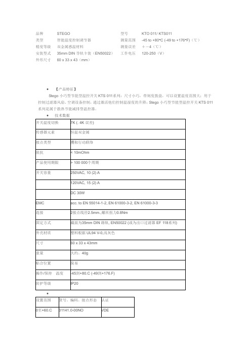
品牌STEGO 型号KTO 011/ KTS011类型智能温度控制调节器测量范围-45 to +80°C (-49 to +176°F)(℃)精度等级双金属感温材料测量误差+-4(℃)安装型式35mm DIN导轨卡装(EN50022)工作电压120-250(V)外形尺寸60 x 33 x 43(mm)∙【产品特征】Stego小巧型节能型温控开关KTS 011系列:尺寸小巧,带刻度拨盘,可以设置温度范围大;用于控制过滤器风扇、空调设备控制,通过激活他们控制温湿度的升降;Stego小巧型节能型温控开关KTS 011系列是属于散热节能减排型温控器。
∙技术数据开关温度切换7K (. 4K误差)传感器元素恒温双金属接点类型攫取行动联络阻抗< 10mOhm产品使用期限> 100 000个周期开关容量250VAC, 10 (2) A120VAC, 15 (2) ADC 30WEMC acc. to EN 55014-1-2, EN 61000-3-2, EN 61000-3-3连接2接点线径2.5mm.,螺丝扭力0.8Nm固定方式截面为35mm DIN路轨, EN50022 (或为出口过滤器EF 118系列)外壳材质塑料根据UL94 V-0,浅灰色尺寸60 x 33 x 43mm重量大约。
40g贴合位置简易操作/保持温度-45到+80.C (-49到+176.F)防护等级IP20∙设置范围货号。
编码。
接点形态认证0至+60.C01141.0-00NO VDE-10至+50.C01143.0-00NO VDE+20至+80.C01158.0-00NO VDE+32至+140.F01141.9-00NO UL文件第E164102 +14至+122.F01143.9-00NO UL文件第E164102 0至+60.C01147.9-00NO UL文件第E164102。
卢顿马斯特罗感应器 说明书

•XCT technology with cross-correlation – no callbacks— Lutron sensors won’t leave you in the dark— Superior sensitivity recognizes the difference between fine human motion and background noise— Provides superior prevention of false-ons and false-offs•Durable design with clean aesthetic— Tamper-resistant lens — Extended relay lifetime•Models for any application and all lighting loads— Single- and dual-circuit switches; neutral and no neutral required — Passive infrared (PIR) and dual-technology sensing — 0-10 V dimmer for 0-10 V fluorescent and LED fixtures — LED + dimmer for dimmable LEDs and CFLs•NEW Wireless models— Delivers the simplicity of an in-wall sensor with the added benefits of Vive — Combines occupancy sensing, manual control, and system connectivity in one piece of hardwareO rder now:Contact your local electrical distributorFor moreinformation:/OccVacSensorsLED + dimmer sensor(formerly C •L)Dual-circuit sensor switch Sensor switch 0-10 V dimmer sensorDual-technology sensor switchDual-technology, dual-circuit sensor switchWireless model availableWireless model available2 | LutronXCT technology with cross-correlation—won’t leave you in the darkLutron sensors detect fine motion, like reading a book, better than other PIR sensors.Breakthrough sensing technology ensures lights stay on when a room is occupied and off when it’s not.Movements like extending your arm Person walking 3 feetSmall movements like flipping pages of a book Lights stay off when room is unoccupied✓✓✓✓Major MotionMinorMotionFine MotionNoFalse-OnXCT technology now available for dual-technology sensors.Dual-technology sensors use PIR and ultrasonic technologies together for maximum sensitivity.Very fine motionMinimal movements like typing on a keyboard✓20406080100F i n e m o t i o n d e t e c t e dFor testing methods see /sensortest638Lutron | 3Durable design with modern, clean aestheticLutron sensors are engineered with robust components, combined with award-winning design.T amper-resistant lens Extended relay lifetime(250,000 on/off switch cycles)Any voltage, any phase(120 V-only sensors also available)Ambient light detection (set to learnable or fixed)Available in 25 colorsControls all lighting and fan loadsLED CFLIncandescent/halogen Electronic low voltage Fluorescent/ LEDLow voltage LED Magnetic low voltage LED + dimmer sensor0-10V dimmer sensor120 VFan•C ombines a Maestro LED + dimmer with an occupancy or vacancy sensor •C ontrols up to 150W dimmable LED/CFL or 600W incandescent/halogen•O ptimized for ideal sensitivity •S ettings are simple to adjust— no dip switches or dials4 | LutronBlackAny voltageAny phase120 V - 277 V 120 V - 277 VPhase A, B, or C Phase A, B, or CEasily reassignChange circuit with button press; no rewiring* Dual-technology no neutral models available, require line- and load-specific wiringCircuit 1Circuit 2Dual-circuitEasy set upNo dip switches or dials•Simple button-press changes settings — Timeout — Sensitivity — Mode• Occupancy• Ambient light detection • Vacancy•0-10 V dimmers and dual-tech models feature easy-to-see LEDs to indicate settings •Dual-circuit models feature independent settings per circuitSensor mode settingsEasy-to-see LEDs and a settings buttonWireless sensors communicate to other wirelessdevices using Lutron’s Clear Connect RF technologyCeiling mountLRF2-OCR2B-P-WHWall mountLRF2-OWLB-P-WHCorner mountLRF2-OKLB-P-WHHallwayLRF2-OHLB-P-WHExtend Coverage•A dd a Radio Powr Savr occupancy/vacancysensor for additional coverage in a spaceMaestro Wireless models0-10V dimmer sensor and 8A sensor switch Enhance controlPico wireless remotePJ2-3BRL-GXX-L01Tabletop pedestalL-PEDX-XXWallplate adapterPICO-WBX-ADPTWallplateCW-1-XXRadio Powr Savrdaylight sensorLRF2-DCRB-WH•M ount a Pico wireless remote to a wall or place it on atabletop stand for flexible control from anywhere in the room•A dd a daylight sensor to dim lightswhen natural light is availableVive wireless hubHJS-0-FMVive Vue softwareMake your system smarter•A dd a Vive wireless hub for centralizedcontrol and integration•U se Vive Vue software to deliver advanced intelligencenecessary for today’s smart buildings and the IoTLutron | 56 |Lutron2A and 5A PIR6 A PIRRF PIRPIR dual-circuit Model numberMS-OPS2-XX* neutral optional (2A model)MS-OPS5M-XX* neutral optional (5A model)MS-OPS6M2-DV-XX* neutral optional MRF2S-8SS-XX* neutral requiredMS-OPS6-DDV-XX*neutral optionalKey applicationsSmall spaceKitchenBreakroom OfficeBathroom Private office Training room Conference room Technology XCT PIR XCT PIR XCT PIR XCT PIR Coverage (sq ft)900 (major) 400 (minor)900 (major) 400 (minor)900 (major) 400 (minor)900 (major) 400 (minor)Timeout 1, 5, 15, or 30 minutes 1, 5, 15, or 30 minutes 1, 5, 15, or 30 minutes 1, 5, 15, or 30 minutes per circuit Voltage120 V120-277 V120V/277V 120-277 V per circuit Amperage/wattage2A lighting (2A model) 5 A lighting (5A model) 3 A (120V) fan (5A model) 6 A lighting 3 A (120 V) fan 8 A lighting6 A lighting 4.4 A fan (120 V) per circuit Single pole, 3-way, multi-location Single pole/3-way/ multi-locationSingle pole/3-way/multi-location Single pole/3-way/multi-location Single poleAmbient light detection Smart SmartSmart or fixedSmartTamper-resistant lens üüüüEnergy code metAutomatic shutoffAutomatic shutoffAutomatic shutoffAutomatic shutoff Multi-level lighting*** XX denotes color suffix** Meets this requirement when bi-level control is allowedLutron |7LED +dimmer sensor 0-10 Vdimmer sensor RF 0-10 V dimmer sensorDual-techDual-tech dual-circuit MSCL-OP153M-XX* no neutral requiredMS-Z101-XX* neutral optionalMRF2S-8SD010V-XX* neutral required MS-A102-XX* no neutral requiredMS-B102-XX*neutral requiredMS-A202-XX* no neutral required MS-B202-XX*neutral requiredKid’s room Kitchen Private office Conference roomConference room Private office Private office BathroomConference room Training roomXCT PIR XCT PIR XCT PIR XCT dual-technology (PIR and ultrasound)XCT dual-technology (PIR and ultrasound)900 (major) 400 (minor)900 (major) 400 (minor)900 (major) 400 (minor)900 (major) 400 (minor)900 (major) 400 (minor)1, 5, 15, or 30 minutes 1, 5, 15, or 30 minutes 1, 5, 15, or 30 minutes 1, 5, 15, or 30 minutes 1, 5, 15, or 30 minutes per circuit 120 V120-277 V 120/277 V 120-277 V 120-277 V per circuit 600 W inc/halogen 150 W LED/CFL 8 A lighting8 A lighting6 A lighting 4.4 A fan (120 V) 6 A lighting 4.4 A fan(120 V) per circuit Single pole/3-way/multi-location Single pole/3-way/multi-location Single pole/3-way/multi-location Single pole/3-way/multi-location(neutral model only)Single pole/3-way (neutral model only)SmartSmart or fixedSmart or fixedSmart or fixedSmart or fixedüüüüAutomatic shutoff Multi-level lighting**Automatic shutoff Multi-level lighting**Automatic shutoff Multi-level lighting**Automatic shutoffAutomatic shutoff Multi-level lighting**Multi-location dimmers/switches work with up to nine companion dimmers/switches, unless RF models, which work with Pico remote controls 3-way dimmers work with mechanical 3-way switches, unless RF models, which work with Pico remote controlsVacancy-only models available. Replace the “O” in the model number with a “V”, or for dual-tech or 0-10 V vacancy models, add -V- before color code (XX)For dual-tech sensors, only neutral optional models allow for 3-way or multi-location applicationsWorld Headquarters 1.610.282.3800Technical Support 1.800.523.9466 (Available 24/7)Customer Service 1.888.LUTRON1 (1.888.588.7661)Largest line of colors availableSensors are available in 13 finishes; 7 gloss and 6 Satin Finishes.• Gloss colors ship in 2 days • Satin colors ship in 2-10 daysCode information/energycodes • Automatic shutoff• Multi-level light controls (dimmers and dual-circuit)• CA Title 20/24 2013• ASHRAE 90.1 2010• IECC 2012All Lutron products backed by world-class support/support• 24/7 live technical support: 1.800.523.9466• Customer service/quotes; 1.888.588.7661Coverage patternsThe Lutron logo, Lutron, Clear Connect, LED +, Maestro, Maestro Wireless, Pico, Radio Powr Savr, Satin Colors, Vive, and XCT are trademarks or registered trademarks of Lutron Electronics Co., Inc., in the U.S. and/or other countries.© 12/2021 Lutron Electronics Co., Inc. IP/N 367-2479 REV J。
美国专业左握式 стра托卡斯特 产品说明书

PARTS LAYOUT2105171213143736101516383940131718192024222317181913181925262124283233465368911273431293233313032333135383940PARTS LISTREF#DESCRIPTION PARTNUMBER 1BODY AM PRO STRAT LH 3TS0048702500 1BODY AM PRO STRAT LH OWT0056239505 1BODY AM PRO STRAT LH BLK0056239506 2NECK ASSY AM PRO STRAT LH RW7709884000 2NECK ASSY AM PRO STRAT LH MPL7709885000 3KEY 2-PIN MTG TALL LH 0073119000 4KEY 2-PIN MTG SHORT LH0073120000 5KEY WASHER 0053106049 6KEY BUSHING 0058820049 7STRING TREE W/HARDWARE0994911000 8SCREW SMAB 3 X 3/8 RHP STL NI0011357049 9NECK PLATE CORONA CA TILT W/HARDWARE0991445100 10SCREW SMA 8 X 1-3/4 OHP NI0015636049 11SET SCREW 1/4-20 X 3/8 OP NI HEX0031571000 12PICKGUARD STRAT AM STD LH P/B/P0056199000 12PICKGUARD STRAT AM STD LH MG/BLK/MG0055320000 13SCREW SMAB 4 X 1/2 OHP NI0015578049 145-WAY SELECTOR SWITCH0991367000 15SCREW MA 6-32 X 5/8 RH NI0994925000 16KNOB PICKUP SWITCH VINT AGED WHITE0994938000 17CONTROL 250K 10% R-AUDIO SPLIT SHAFT0063892000 18NUT HEX 3/8-32 X 3/320016352049 19WASHER LCK INTNL 3/8 X 500 X .02 NI0022384049 20CAPACITOR CD 1200pF 1000V 10%0065862000 21CAPACITOR MPF RDL .022MF 250 V 10%0024832049 22RES CF 1/4W 20K 5%0029006001 23RES CF 1/4W 150K 5%0024999001 24KNOBS STRAT 1-VOL 2-TONE AGED WHITE 0991369000 25FERRULE JACK CHROME 0991940000 26JACK PHONE OPEN CIRCUIT 110021956049 27BRIDGE ASSY AM PRO STRAT LH7709951000 27A BRIDGE PLATE TREM AM PRO STRAT LH CHROME7709900000*=NOT PICTURED IN DIAGRAMREF#DESCRIPTION PARTNUMBER 27B BLOCK TREMOLO AM DLX STRAT LH SILVER MET0077091000 27C BRIDGE SECTION ASSY NI AS STRAT SHORT0075123101 27D BRIDGE SECTION ASSY NI AS STRAT TALL0075123102 27E SPRING BRIDGE #1932 0019281049 27F SCREW M 4-40 X 5/8 RHP NI0015693049 27G SCREW M 8-32 X 3/8 FHP NI 0019656049 27H SPRING CLIP ULTRA0036531000 27I BUSHING NYL NAT .31 OD X .191 ID X .87 L7710005000 27J SET SCREW 10-32 X 3/16 HEX SKT FP BLX 0036615049 28PICKUP AM PRO SHAW BRIDGE LH AGED WHITE7709879000 29PICKUP AM PRO SHAW MIDDLE LH AGED WHITE7709891000 30PICKUP AM PRO SHAW NECK LH AGED WHITE7709893000 31PICKUP COVERS STRAT VINTAGE AGED WHITE0053824049 32TUBING LATEX CUT .300 X 1/8 ID X 1/4 OD0994916000 33SCREW TF 6-32 X 3/4 RHP STL NI0099346000 34BRIDGE PIVOT POST ASSY0093273000 35BACK COVER STRAT STD W/SLOT LH MG/BLK/MG0055322000 35BACK COVER STRAT STD W/SLOT LH P/B/P0056214000 36SPRING TREMOLO TENSION BLX 0018671049 37TREM CLAW SPRING TENSION ZINC0010272100 38STRAP BUTTONS CHROME W/HARDWARE0063267049 39FELT WASHERS WHITE0994930000 39FELT WASHER BLACK0994929000 40WOOD SCREW 6 X 1 OHP NI0016188049 *CASE AM ELITE GUITAR7710537000 *TRMOLO ARM AM PRO STRAT RH POLISHED SS7709929000 *TREMOLO ARM KNOB VINT AGED WHITE0994933000 *WRENCH HEX KEY 1/80023811049 *WRENCH HEX KEY .0500018531049 *WRENCH HEX KEY 1/160021109049 *WRENCH HEX KEY 3/320018622000*=NOT PICTURED IN DIAGRAMWIRING ASSEMBLY1200p F1200p FVOLUME CONTROL5-WAY SWITCHTONE 1CONTROLBLACK & WHITE WIRES FROM OUTPUTBLACK WIRE TO TREM CLAWGROUND LUG TO BODY CAVITYTONE 2 CONTROLCAPACITOR .022µFNECK PICKUPMIDDLE PICKUPBRIDGE PICKUPCAPACITOR 1200pFRESISTOR 20K ΩSHRINK TUBE CAPACITOR LEGSRESISTOR 150K ΩSWITCH AND CONTROL FUNCTION43215TONE CONTROLOF 5-WAY SWITCHINDICATES POSITION 5-WAYSWITCH POSITIONPICKUP IS OFFPICKUP IS ON 1BRIDGE PICKUP5 WAY SWITCH POSITIONNECK PICKUPMIDDLE PICKUPT1T1 & T2T2T2T2MASTER VOLUME 5-WAY SWITCHTONE 1 (T1)TONE 2 (T2)NECK PICKUP MIDDLE PICKUPBRIDGE PICKUPADDITIONAL SPECIFICATION DETAIL.054”.094”2-7/16”.820”.920”10-32THREAD.050” HEXØ.375”1/8” HEXSTAGGERED TUNING MACHINE SET W/HDWR P/N 0990820100OUTER SHAFT DIAMETER .394”TUNING MACHINE THRU-HOLEINNER DIAMETER .404”LOGO: AMERICAN PRO STRAT LHAPPLIED UNDER THE FINISHTRUSS ROD NUT P/N 0994943000TRUSS ROD ADJUSTMENT WRENCH:1/8” HEX KEY P/N 0023811049SADDLE HEIGHT ADJUSMENT WRENCH:.050” HEX KEY P/N 0018531049SHORT: P/N 0075536000TALL: P/N 00753840001ST FRET PROFILE12TH FRET PROFILENECK PROFILE: MODERN DEEP “C”FRET SIZE: JUMBO NARROW(FRET DIMENSIONS ARE BEFORE INSTALLATION)Ø.404”Ø.394”PLEASE NOTE: AS EACH NECK IS SANDED & FINISHED BY HAND, THICKNESS DIMENSIONS MAY VARY SLIGHTLY FROMTHOSE SHOWN.SADDLE HEIGHT ADJUSTMENT SCREWS:PICKUP SPECIFICATIONSNECKMIDDLE BRIDGEDC RESISTANCE 6.1 - 6.7KΩ6.4 -7.0KΩ6.4 - 7.0KΩMAGNETS ALNICO 2 & 3BEVELEDALNICO 5 & 2BEVELEDALNICO 5BEVELEDPOLARITY SOUTHNORTHSOUTHPOSITION。
行动器3000系列2100W功率30g 分钟连续蒸汽140g蒸汽爆发陶瓷DST3011 26说明书

3000 Series2100 W power30g/min continuous steam140 g steam boostCeramicDST3011/26Powerful steam to tackle every creaseSteamboost up to 140gOur steam iron 3000 series makes ironing easy with the powerful steam boostthat tackles tough creases.The ceramic soleplate ensures smooth gliding while the300ml water tank is large enough to finish smaller ironing loads without a refill.Easy ironingIron more in one go with the 300ml water tankSmooth gliding ceramic soleplateOur drip stop prevents water dripping on your garmentReach difficult places easily with the triple precision tipVertical steaming for hanging fabricsLong lasting performanceBuilt-in calc-clean slider, long-lasting steam performanceFast ironing2100 watt for fast heat-upContinuous steam up to 30 g/min for consistant performanceSteam boost up to 140 gram for extra powerSteam iron DST3011/26 Highlights SpecificationsSteam boost up to 140 gramThe strong steam boost gives you that extra power to penetrate deeper into the fabric and cut through the tough creases easily. Continuous steam up to 30g/minStrong and consistent steam output to remove creases faster.2100 watt for fast heat-upDelivers fast warm-up and powerful performance.Ceramic soleplateOur durable ceramic soleplate glides well on any ironable garment. It does not stick to your garment, is scratch resistant and easy to keep clean.Drip stopOur drip-stop system prevents leakage to avoid stains from water droplets, so you can iron with confidence at any temperature.Vertical steamWith the vertical steam function you can refresh garments right on the hanger and remove creases from hanging fabrics such as curtains. No ironing board required.Triple precision tipThe tip is precise in 3 ways: it has a pointedtip, button groove and sleek nose design. Ourtriple precision tip helps you handle even thehardest-to-iron spots, like buttons and pleats.Built-in calc-clean sliderThis iron operates with ordinary tap water.Calc-clean is a built-in cleaning function toremove calcium buildup, or limescale, andmaintain peak performance.300ml water tankFewer refills are required thanks to a large300ml water tank. So you can iron moreclothes in one go.Easy to useWater tank capacity: 300 mlPower cord length: 1.9 mTap water suitableDrip stopSoleplate: CeramicVertical steamVoltage: 220-240 VWater spraySize and weightPackaging dimensions (WxHxL):32x13x16.2 cmProduct dimensions (WxHxL): 12.1x14.3x29 cmTotal weight with packaging: 1.5 kgWeight of iron: 1.2 kgGuarantee2 year worldwide guaranteeGreen efficiencyEnergy saving modeProduct packaging: 100% recycableUser manual: 100% recycled paperCalc managementBuilt-in Calc Clean SliderDescaling and cleaningPowerful performanceContinuous steam: 30 g/minPower: 2100 WReady to use: 35 sec.Steam boost: Up to 140 gram© 2021 Koninklijke Philips N.V.All Rights reserved.Specifications are subject to change without notice. Trademarks are the property of Koninklijke Philips N.V. or their respective owners.Issue date 2021‑05‑17 Version: 1.0.1。
Stethoscope
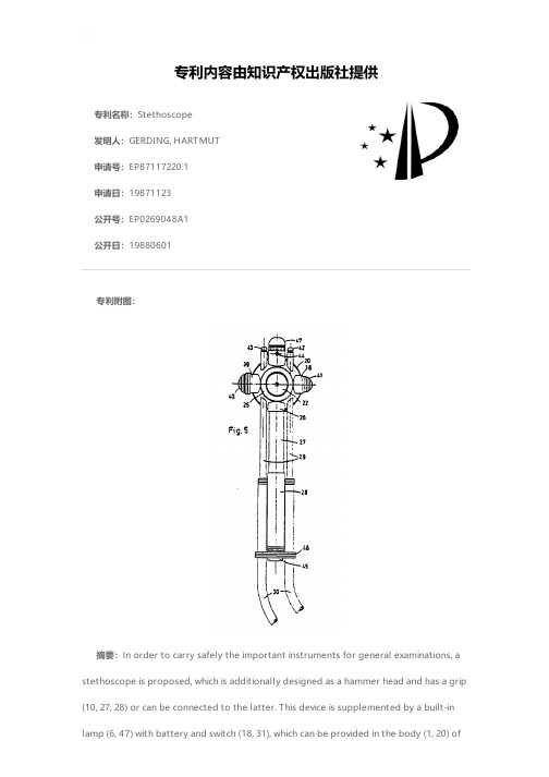
专利名称:Stethoscope发明人:GERDING, HARTMUT申请号:EP87117220.1申请日:19871123公开号:EP0269048A1公开日:19880601专利内容由知识产权出版社提供专利附图:摘要:In order to carry safely the important instruments for general examinations, a stethoscope is proposed, which is additionally designed as a hammer head and has a grip (10, 27, 28) or can be connected to the latter. This device is supplemented by a built-in lamp (6, 47) with battery and switch (18, 31), which can be provided in the body (1, 20) ofthe stethoscope, in the grip and/or in a forkpiece (13) joining the individual tubes together. The device is further supplemented by a conventional reflex needle (42) which can be accommodated in it, so that, even when picked up quickly, the important examination instruments are at all times held together, and the loss or the mislaying of individual instruments is in practice prevented.申请人:GERDING, HARTMUT,HACHENBERG, GUNTER地址:Voltastrasse 65 D-4150 Krefeld DE,Untere Metzgerstrasse 22 D-5900 Siegen DE 国籍:DE,DE代理机构:Grosse, Dietrich, Dipl.-Ing.更多信息请下载全文后查看。
高斯特罗部件-电子组件及热元件说明书

[EN][DE][ES][FR][IT][PL][RU]***************************3Find the complete and up-to-date range of products on https://1e l e c t r i c c o m p o n e n t sPart No.418639Ref. No.RATIONAL heATINg eLemeNTs1Part No.420519Ref. No.Part No.417678Ref. No.Part No.4177091Ref. No.1Part No.417694Ref. No. Part No.417714Ref. No.heating elements RatiOnal4Find the complete and up-to-date range of products on https://5Find the complete and up-to-date range of products on https://1e l e c t r i c c o m p o n e n t sPart No.4177101Ref. No.1Part No.417711Ref. No.Part No.417646Ref. No.heating elements for convectionPart No.693548Ref. No.flange suitable for convection heating element W 23mm mountingPart No.693546Ref. No.description flange suitable for convection heating element W 47mm mounting pos. outer length 210RATIONAL heATINg eLemeNTs1Part No.417670Ref. No.heating element 15000W 230V heating circuits 6 ID ø 505mm ED øPart No.417675Ref. No.Part No.418381Ref. No.Part No.417676Ref. No.heating element 18000W 230V heating circuits 3 ID ø 410mm ED øPart No.417671Ref. No.Part No.417677Ref. No.heating element 18000W 230V heating circuits 6 ID ø 407mm ED øheating elements RatiOnal6Find the complete and up-to-date range of products on https://7Find the complete and up-to-date range of products on https://1e l e c t r i c c o m p o n e n t s Part No.418380Ref. No.heating element 18000W 230V heating circuits 6 ID ø 415mm ED Part No.417674Ref. No.Part No.418379Ref. No.description heating element 20000W 230VFor models:CM62, SCC62Part No.418375Ref. No.Part No.417683Ref. No.Part No.418377Ref. No.Part No.417689Ref. No.heating element 9000W 230V heating circuits 3 ID ø 385mm ED RATIONAL heATINg eLemeNTs1Part No.417690Ref. No.heating element 9000W 230V heating circuits 3 ID ø 407mm ED øPart No.418378Ref. No.heating element 9000W 230V heating circuits 3 ID ø 410mm ED øPart No.417691Ref. No.heating element 9000W 230V heating circuits 3 ID ø 440mm EDø 453mm L 470mm H 140mm L1 20mm W1 163mm H1 30mm H2Part No.417692Ref. No.heating element 9000W 230V heating circuits 3 ID ø 445mm ED øPart No.417693Ref. No.heating element 9000W 230V heating circuits 3 ID ø 504mm ED øPart No.417697Ref. No.heating element 9000W 230V heating circuits 4 ID ø 310mm EDheating elements RatiOnal8Find the complete and up-to-date range of products on https://9Find the complete and up-to-date range of products on https://1e l e c t r i c c o m p o n e n t s Part No.417698Ref. No.heating element 9000W 400V heating circuits 3 ID ø 385mm ED Part No.415239Ref. No.descriptionheating element 9000W 400V heating circuits 3 ID ø 440mm ED ø 453mm L 465mm H 140mm L1 15mm W1 150mm H1 30mm H2RATIONAL heATINg eLemeNTs1thermostatsPart No.375160Part No.375086descriptionthermostat t.max. 180°C temperature range 60-180°C 1-pole 1CO16A probe ø 6mm probe L 90mm capillary pipe 2400mm capillarypipe isolated 2300mm gland nut shaft ø 6x4.6mm shaft L 25mm shaftPart No.375401Ref. No.descriptionthermostat t.max. 185°C temperature range 97-185°C 1-pole 1NO16A probe ø 6mm probe L 87mm capillary pipe 1430mm capillarypipe isolated 1100mm gland nut M9x1 shaft ø ø6x4.6mm shaft LPart No.375087descriptionthermostat t.max. 300°C temperature range 50-300°C 1-pole 1CO16A probe ø 3.03mm probe L 160mm capillary pipe 1130mm capil-lary pipe isolated 1103mm gland nut shaft L 23mm shaft positionPart No.375066descriptionthermostat t.max. 300°C temperature range 60-300°C 1-pole 1CO16A probe ø 4mm probe L 98mm capillary pipe 1450mm capillarypipe isolatedmm gland nut shaft ø 6x4.6mm shaft L 25mm shaftPart No.375088descriptionthermostat t.max. 300°C temperature range 60-300°C 1-pole 1NO16A probe ø 4mm probe L 100mm capillary pipe 830mm capillarypipe isolated 800mm gland nut shaft L 15mm shaft position upperthermostats ratIoNaL10Find the complete and up-to-date range of products on https://11Find the complete and up-to-date range of products on https://1e l e c t r i c c o m p o n e n t s Part No.375085descriptionthermostat t.max. 90°C temperature range 0-90°C 1-pole 1CO 16A probe ø 3.1mm probe L 247mm capillary pipe 1430mm capillary pipe isolated 1400mm gland nut shaft ø 6x4.6mm shaft L 18mm shaft Part No.375074descriptionsafety thermostat switch-off temp. 365°C 2-pole 16A probe ø 4mm probe L 116mm capillary pipe 1170mm capillary pipe isolated 1100mm gland nut probe with special screwing screw connection Part No.375090descriptionsafety thermostat switch-off temp. 365°C 2-pole 16A probe ø 4mm probe L 120mm capillary pipe 1170mm capillary pipe isolated Part No.375084descriptionsafety thermostat switch-off temp. 135°C 1-pole 10A probe ø6mm probe L 83mm capillary pipe 1440mm capillary pipe isolated Part No.375776descriptionsafety thermostat switch-off temp. 135°C 1-pole 10A probe ø6mm probe L 87mm capillary pipe 1440mm capillary pipe isolated Part No.375775descriptionsafety thermostat switch-off temp. 160°C 1-pole 10A probe ø6mm probe L 87mm capillary pipe 1440mm capillary pipe isolated 1400mm gland nut probeRATIONAL TheRmOsTATs1Part No.375984Ref. No.descriptionsafety thermostat switch-off temp. 225°C 3-pole 3NC 20A probe ø6mm probe L 94mm capillary pipe 900mm capillary pipe isolated670mm gland nut M10x1 probe SSPart No.375890descriptionsafety thermostat switch-off temp. 650°C 3-pole starting tempera-ture 624°CPart No.390797Ref. No.descriptionsafety thermostat switch-off temp. 157°C 1-pole 16A probe ø6mm probe L 62mm capillary pipe 1520mm capillary pipe isolated1380mm gland nut probePart No.375862descriptionsafety thermostat switch-off temp. 183°C 1-pole 16A probe ø6mm probe L 61mm capillary pipe 1460mm capillary pipe isolated1400mm gland nut probe SSPart No.390977Ref. No.descriptionsafety thermostat switch-off temp. 360°C 1-pole 16A probe ø 4mmprobe L 102mm capillary pipe 1200mm capillary pipe isolated820mm gland nut 1/4“ probe SSPart No.375774safety thermostat switch-off temp. 365°C 1-pole 16A probe ø4mm probe L 96mm capillary pipe 1160mm capillary pipe isolatedthermostats ratIoNaL1e l e c t r i c c o m p o n e n t s Part No.375159safety thermostat switch-off temp. 365°C 1-pole 16A probe øPart No.375083descriptionthermostat t.max. 250°C temperature range 60-250°C 1-pole 1NO 16A probe ø 4mm probe L 100mm capillary pipe 3150mm capillary pipe isolated 3090mm gland nut shaft ø ø6x4.6mm shaft L 23mm Part No.375570Ref. No.descriptionthermostat t.max. 470°C temperature range 100-470°C 1-pole 1NO 16A probe ø 3.9mm probe L 228mm capillary pipe 1110mm capillary Part No.375739Ref. No.switches and momentary switchespush/momentary push switchesPart No.347178Part No.346508Part No.345136RATIONAL TheRmOsTATs /swITches ANd mOmeNTARy swITches1Part No.345125Part No.345216Part No.347949Part No.400023Ref. No.Part No.300048Ref. No.description cam switch 2 operating positions core temperature sequence 1-2 shaft ø 6x4.6mm connection male faston 4-polePart No.300046Ref. No.cam switch 4 operating positions 5NO sequence 0-1-2-3 16A shaft ø switches and momentary switches rationaL1e l e c t r i c c o m p o n e n t sPart No.300049Ref. No.description cam switch 4 operating positions 8NO sequence 0-1-2-3 16A shaft ø Part No.300070Ref. No.description cam switch 5 operating positions 9NO sequence 0-1-2-3-4 16A shaft ø 6x4.6mm shaft L 23mm connection male faston 6.3mm plastic Part No.300051Ref. No.description cam switch 6 operating positions 2NO sequence 1-0-2-3-4-5 6A shaft ø 6x4.6mm shaft L 33mm connection male faston 6.3mm plastic rotary switchesPart No.300052Ref. No.description rotary switch 2 1-2 sets of contacts 4 type D1155N 400V 12A connec-tion screwPart No.300047Ref. No.description rotary switch 4 operating positions 9-pole For models:CD101, CD20, CD201Part No.345217Ref. No.RATIONAL swITches ANd mOmeNTARy swITches1Part No.346510Ref. No.description magnetic switchPart No.3465151Ref. No.1Part No.345109Ref. No.Part No.346511descriptionmagnetic switch 230V 0.2A P max. 50W probe L 60mm 1NO connec-Part No.346514Part No.345110magnet ømm L 25mm H 9mm W 15mmPart No.541986description magnet holder with magnet ø 13mmswitches and momentary switches rationaL1e l e c t r i c c o m p o n e n t s control equipmentPart No.345174Part No.345207push button mounting measurements ø22mm transparent reset Part No.110261descriptionrotary selectorPart No.110260Part No.347709Part No.359606Part No.300198Part No.300196description potentiometer 0-150RATIONAL cONTROL equIpmeNT /eNcOdeRs ANd pOTeNTIOmeTeRs1encoders and potentiometers/lamps rational Part No.403719Part No.300197potentiometer 4.7KOhm rotation 360° shaft ø 5.9mm with switchPart No.300000Part No.300058Part No.300059Part No.300266Part No.Part No.359598Part No.359608Part No.359597description light bulb socket T10 24V 2W ø 10mm L 28mm1e l e c t r i c c o m p o n e n t s RATIONAL LAmpsPart No.359606Part No.359585Part No.359886Part No.Part No.359887Part No.359606Part No.3595851lamps RaTIONal Part No.359610Part No.359598Part No.359608Part No.359597description light bulb socket T10 24V 2W ø 10mm L 28mmPart No.359596oven lampsPart No.359720oven lamp mounting ø 35.5mm 230V 15W socket E14 temp.-resist.Part No.3597011e l e c t r i c c o m p o n e n t s RATIONAL LAmpsPart No.359723Part No.359705description oven lamp glass thr.ø 33.5mm ø 52mm hard glas temp.-resist. 350°CPart No.359888Part No.359876Part No.3598801lamps RaTIONal Part No.359879Part No.360724Part No.359877Part No.359873Part No.359882Part No.359881Part No.359878Part No.359874Part No.3598751e l e c t r i c c o m p o n e n t s RATIONAL LAmps /TImeRs /ALARm devIcesPart No.359610Part No.359888timerselectric timersPart No.350015timer MS65 without bell operation time 120min time spreadminPart No.350074alarm devicesbuzzersPart No.3501361alarm devices/contactors rational Part No.350053Part No.350050Part No.350091Part No.380772Part No.381501Part No.3820011e l e c t r i c c o m p o n e n t s RATIONAL cONTAcTORsPart No.381203descriptionpower contactor resistive load 65A 230VAC (AC3/400V) 32A/15kW main contacts 3NO auxiliary contacts 1NO connection screw connec-Part No.381180description power contactor resistive load 80A 230VAC (AC3/400V) 40A/18.5kW Part No.3806781contactors ratIonaL Part No.380267Part No.380498power contactor resistive load 20A 230VAC (AC3/400V) 9A/4kW main1e l e c t r i c c o m p o n e n t s RATIONAL cONTAcTORsPart No.3802611contactors ratIonaLPart No.380269Part No.1e l e c t r i c c o m p o n e n t s RATIONAL cONTAcTORsPart No.380268Part No.Part No.380169Ref. No.description motor protection circuit breaker Part No.380170Ref. No.description motor protection circuit breaker For models:CC201, CD20, CD201, CM201MOELLER/EATONPart No.380515Part No.380171descriptionpower contactor resistive load 20A 230VAC (AC3/400V) 9A/4kW main contacts 3NO auxiliary contacts 1NO connection screw connection1contactors ratIonaLPart No.380163Ref. No.description motor protection circuit breaker type PKZMPart No.380175TELEMECANIQUE (Schneider Electric)Part No.380367Part No.3801881e l e c t r i c c o m p o n e n t s RATIONAL cONTAcTORsPart No.380300description motor protection circuit breaker type Mbs25-016 setting range 1-1.6A (AC3/400V) 0.55kW Part No.380301description motor protection circuit breaker type Mbs25-025 setting range 1.6-2.5A (AC3/400V) 1.1kW Part No.380304description motor protection circuit breaker type MS25-10 setting range 6.3-10A (AC3/400V) 4kWPart No.380305auxiliary contact contacts 1NO/1NC HMS11Part No.380397descriptionsmall relay switch 24V main contacts 1NO/1NC connection Faston miscellaneous1contactors/solid state relays rationalPart No.381225Ref. No.description power contactor setPart No.401672Ref. No.descriptionsolid state relay CELDUC 2 phase 50A 24-600V 7.5-25VDC L 58mm W46mm jumper at L1 and L2 screw type SOB665200 7.5-25VDCPart No.400105Ref. No.1e l e c t r i c c o m p o n e n t s RATIONAL sOLId sTATe ReLAys /ReLAysPart No.401670Ref. No.descriptionsolid state relayPart No.380502description power relays connection 2.0 plug-in connectionplug-in/print relaysPart No.380501description print relay 12VDCPart No.380281Part No.380283time relay FINDER 82.41.0.240 time range 0.05s-10h 24-240VAC/24-Part No.380319description time relay pickup-delayed 0.06-150sPart No.3802801relays/transformers ratIonalPart No.380282time relay WIELAND NGZ310 time range 1.5-30s 24-240V AC/DC 5Atransformersopen transformersPart No.400104descriptiontransformer primary 230VAC secondary 24VAC 40VA secondary 1.7Aconnection screw 50/60Hz with fusePart No.403774descriptiontransformer primary 400/415/440/480 secondary 240/208 320/820VAsecondary 1.33A H 107mm L 120mm W 105mm type block for com-Part No.403057transformer primary 400/415/440/480V secondary 208/240VPart No.400101description transformer primary 200-260VAC secondary 4.2/14.4/11.5VAC 68.4VAPart No.400117descriptiontransformer primary 200-230V secondary 11.5V 20VA 50/60Hz tem-perature restriction 131°C ambient temperature max. 60°CPart No.400102description transformer primary 230VAC secondary 11.5VAC 10VA1e l e c t r i c c o m p o n e n t s RATIONAL TRANsfORmeRs /eLecTRONIc cONTROLLeRsPart No.400118description transformer primary 230VAC secondary 21VAC 35VA Part No.401472descriptiontransformer 1/20/50VA secondaryA H 70mm L 76mm W 104mm connection plug 50/60Hz type 110170 with fuse secondary Part No.401473description transformer 21.6VA H 70mm L 94mm W 71mm connection plug 50-60Hz type 40.00.592 moulded secondary 12VDC primary 200-250VAC Part No.401470description transformer primary 230V secondary 11.5V 10VA Part No.401471description transformer primary 230V secondary 11.5V 20VAelectronic controllersELIWELLPart No.378303Ref. No.electronic controller ELIWELL type IDPlus 902 mounting measure-Table continues overleaf1electronic controllers/probes rAtionAlprobesproducer-specific probesPart No.381430Ref. No.3014.1000temperature probe thermocouple K (NiCr-Ni) cable silicone probe1e l e c t r i c c o m p o n e n t s RATIONAL pRObesPart No.379425Ref. No.3014.0157Part No.378351Ref. No.40.03.528Part No.379864Ref. No.40.00.395 40.00.594 40.01.097 40.01.099Part No.379441Ref. No.40.00.291Part No.379869Ref. No.40.00.287 40.00.398 87.00.058Part No.379442Ref. No.40.01.0941probes rATIoNALPart No.693523Ref. No.22.00.479descriptionbracketPart No.693522Ref. No.22.00.480descriptionbracket for core temperature probePart No.693524Ref. No.22.00.453descriptionbracket for core temperature probe L 80mm ø 16mm40.00.298Part No.378646Ref. No.24.01.122descriptioncore temperature probe cable PTFE connection coded plug probe ø3x100mm cable length 2.7m handle ø 12mm handle length 44mmPart No.381443Ref. No.40.04.040Pdescriptioncore temperature probe CM_P 61-102 cable PTFE insulated probe -40 up to +250°C probe ø3x100mm cable length 2.45m handle ø 12mm handle length 44mm1e l e c t r i c c o m p o n e n t s RATIONAL pRObes3035.0714 1multipoint probe40.00.295 140.02.100Part No.379865Ref. No.40.00.296 40.00.297 40.00.608Part No.3798661Ref. No.40.00.293 40.00.294 40.00.606 11probes /electronics rAtionAlPart No.550366Part No.901571Ref. No.Part No.403018Ref. No.description EPROM type CPC CODE XS5.06S For models:CPC101, CPC102, CPC201, CPC202, CPC61Part No.400084description control PCBFor models:CCM101, CCM102, CCM201, CCM202, CCM61Part No.400100Ref. No.description control PCBFor models:CCC101, CCC102, CCC201, CCC202, CCC61Part No.402920description control PCB combi-steamer CD 101/CM 101 suitable for RATIONAL For models:CD101, CD102, CD201, CD202, CD61, CM101, CM102, CM201, CM202,1e l e c t r i c c o m p o n e n t s RATIONAL eLecTRONIcsPart No.400098Part No.400103Ref. No.description control PCB combi-steamer CM 61-202 L 460mm W 154mm 61-202Part No.400099Ref. No.description control PCB combi-steamer CM101For models:CM101, CM102, CM201, CM202, CM61Part No.400107description control PCB combi-steamer CM101 edition CM v. 4.91-97For models:CM101, CM201Part No.402827Ref. No.Part No.403319description control PCB combi-steamer CPC-Linie CM 61-202/G model since 10/1997Part No.401475Ref. No.Part No.403796Ref. No.1electronics rAtionAlPart No.403797Ref. No.control PCB for combi-steamer SCC_WE, CM_P 61-202 modelPart No.400109description control PCB regulation and control electronicsFor models: CM101, CM201Part No.403889Ref. No.description display for combi-steamer SCC_WE 61-202 complete incl. controlPart No.401490Part No.401938Ref. No.description keypad PCBPart No.400129Ref. No.1e l e c t r i c c o m p o n e n t s RATIONAL eLecTRONIcsPart No.401493Ref. No.description PCBFor models:CM101, CM201, CM62Part No.401479Ref. No.Part No.400077Ref. No.description PCB combi-steamer CCD 101/201 core temperature Part No.401487description PCB combi-steamer CD 101/CM 101 with axial flow fan for fan motor Part No.401662Ref. No.Part No.400110Ref. No.Part No.400033description PCB for gas valve 240V 28V1electronics/keypads/solenoid valves rationalPart No.401013motor break electronic 50/60Hz for RATIONAL breaking duration 4skeypadsfront foilsPart No.403795description front foil for combi-steamer SCC Line L 540mm W 175mmPart No.401012Part No.403781Ref. No.description membrane keypad for combi-steamer SCC Line L 230mm W 124mmPart No.373021Part No.3730171e l e c t r i c c o m p o n e n t s RATIONAL sOLeNOId vALvesPart No.370852description solenoid valve single straight 230VAC inlet 3/4“ outlet 11.5mm DN10Part No.370853solenoid valve single straight 230VAC inlet 3/4“ outlet 11.5mm input Part No.370851solenoid valve double straight 230VAC inlet 3/4“ outlet 11.5mm Part No.371016Part No.370065solenoid valve double straight 230VAC inlet 3/4“ outlet 11.5mm1solenoid valves RaTionalPart No.370368solenoid valve single straight 230VAC inlet 3/4“ outlet 11.5mm DN10Part No.370006Part No.370195solenoid valve body double straight inlet 3/4“ outlet 11.5mm DN10Part No.370133solenoid valve body single straight inlet 3/4“ outlet 11.5mm DN10Part No.370132solenoid valve body triple straight inlet 3/4“ outlet 11.5mm DN101e l e c t r i c c o m p o n e n t s RATIONAL sOLeNOId vALvesPart No.Part No.370672Part No.370371Part No.370370Part No.370372Part No.370840Part No.3702701solenoid valves/pressure switches rationalPart No.371323solenoid valve filter ø 19.5mm H 10.5mm suitable for RATIONALPart No.699812pressure switchesPart No.541108description pressure controlPart No.541111for combi-steamersPart No.345709pressure control ø 84mm pressure range 0-3mbar for humidity mea-Part No.3452181e l e c t r i c c o m p o n e n t s RATIONAL pRessuRe swITches /eLecTROdesPart No.541329Part No.403298Ref. No.Part No.403297Ref. No.44.00.514 87.01.219Part No.400163Ref. No.Part No.403138Ref. No.descriptionlevel electrode PG9 total length 100mm probe L 85mm insulated probe length 70mm with connection cable connection coded plugPart No.400021Ref. No.Part No.400022Ref. No.Part No.401492description level electrode probe L 85mm1electrodes/flow meters and flow sensors/fans ratIonal Part No.401491Ref. No.Part No.403886Ref. No.Part No.403804Ref. No.44.00.28744.01.37187.01.221flow meters and flow sensorsflow sensorsPart No.403301Ref. No.flow sensor inlet ø 10mm outlet ø 10mm L 104mm connectionPart No.402256Ref. No.Part No.403302Ref. No.Part No.6010301descriptionaxial fan L 119mm W 119mm H 38mm 230VAC 50Hz 18W bearingball bearing manuf. no. 4656Z metal connection male faston 2.8mmebm-papst fan wheel ø 110mm temp.-resist. 75°C1with ball bearingsPart No.6013091descriptionaxial fan L 127mm W 127mm H 38mm 12VDC 21W bearing ball bea-ring manuf. no. DV5212N metal connection cable ebm-papst suitablefor RATIONAL fan wheel ø 120mm temp.-resist. 65°C11e l e c t r i c c o m p o n e n t s RATIONAL fANsPart No.6017521descriptionaxial fan L 127mm W 127mm H 38mm 12VDC 21W bearing ballbearing manuf. no. DV5212N plastic/metal connection cable 310mm ebm-papst fan wheel ø 120mm temp.-resist. 65°C SCC Line since 1Part No.6011131Ref. No.3101.1013descriptionaxial fan L 172mm W 150mm H 38mm 230VAC 50/60Hz 27/28W bea-ring ball bearing connection male faston 2.8mm manuf. no. 7056ES metal ebm-papst fan wheel ø 145mm temp.-resist. 55°CCM102, CM201, CM202, CPC102, CPC201, CPC2021Part No.6010801descriptionaxial fan L 119mm W 119mm H 38mm 230VAC 50/60Hz 23/20W bearing ball bearing connection male faston 2.8mm metal ADDA fan wheel ø 110mm temp.-resist. 70°C1with ball bearingsPart No.6017121descriptionaxial fan L 120mm W 120mm H 38mm 12VDC 10W bearing ball bea-ring connection cable 320mm plastic ADDA fan wheel ø 110mm1with ball bearingsPart No.6016701descriptionaxial fan L 80mm W 80mm H 25mm 12VDC 1.8W bearing ball bearing connection cable 300mm fan wheel ø 75mmCD101, CD102, CD201, CD202, CD61, CM101, CM102, CM201, CM202, 1Part No.602141descriptionguard with filter for axial flow fan L 126mm W 126mm H 13.5mm mounting distance 115mm suitable for ebm-papst。
特殊番茄椅子操作手册说明书

ON CHAIR STATIONARY BASE MOBILE BASE FLOOR SITTERIN PUSH CHAIRSModel# Series77XXXXXX & 78XXXXXX UMSTS03-15LITSoft-Touch ™Sitter User ManualParts5 Ways To Use Your Special Tomato ® Sitter1 Sitter with 5-point harness2 Attachment strapsUSE UNIVERSAL ATTACHMENT STRAPS TO SECURE SITTER IN THE BELOW APPLICATIONSUNIVERSALThreading & ConnectionsHarness DiagramPelvic Harness InstallationCHEST STRAPS 5-POINT HARNESS3-POINT PELVIC HARNESS WAIST & CROTCH STRAPSATTACHMENT STRAPTO ATTACH TO A CHAIR, ETC.Harness InstalledSTEP 1CROTCH STRAP UP THROUGH BOTTOM CENTER SLOT.STEP 2RIGHT WAIST STRAP UP THROUGH RIGHT SLOT.STEP 3LEFT WAIST STRAP UP THROUGH LEFT SLOT.STEP 4CLIP BUCKLING.Chest Harness InstallationAttachment Strap InstallationSTEP 1UNCLIP RIGHT CHEST STRAP AND SLIDE STRAP THROUGH LEFT SHOULDER SLOT.STEP 2THREAD STRAPPING AROUND THE BACK AND OUT THE RIGHT SHOULDER SLOT.STEP 3CLIP TO THE TOP OF THE RIGHT SHOULDER CHEST HARNESS.STEP 4UNCLIP RIGHT LATERAL STRAP AND SLIDE STRAPTHROUGH LEFT WAIST SLOT.STEP 5THREAD STRAPPING UNDER THROUGH CROTCH LOOP AND UP AND OUT THE RIGHT SLOT.STEP 6REATTACH THE CHEST CLIP TO THE BOTTOM OF THE RIGHT SIDE OF THE CHEST HARNESS.STEP 1THREAD STRAP DOWNTHROUGH THE LEFT WAIST SLOT.STEP 2THREAD STRAP UNDERSITTER ON TOP OF LOOP ANDUP RIGHT WAIST SLOT.Attachment Straps & ApplicationsATTACH TO A CHAIRATTACH TO A SPECIAL TOMATO® WOODEN BASEATTACH TO A SPECIAL TOMATO® FLOOR BASE*BACK STRAPNOT NECCESSARY*POSITION SO THATBUCKLE IS ON SIDE ATTACH TO A SPECIAL TOMATO® JOGGER, EIO OR PUSH CHAIR*INSTALLEDProper Adjustment TechniquesSitter Harness FittingUSE THE SHOULDER COVERS TO PREVENT YOUR CHILD’S NECK AND FACE FROM RUBBING ON THE PLASTIC BUCKLES.TO ENSURE PROPER PLACEMENT OF THE CHESTHARNESS ON YOUR CHILD, MAKE SURE THE CHEST STRAP LAYS IN THE MIDDLE OF THE CHEST (NIPPLE LEVEL).THE PELVIC HARNESS HAS A CAM LOCK WHICH PREVENTS THE PELVIC BELT FROM LOOSENING TO MAINTAIN PROPER POSITIONING OF THE PELVIS.THE PELVIC BELT HAS ONE QUICK-RELEASE BUTTON THAT UNLOCKS BOTH SIDES OF THE PELVIC HARNESS FOR QUICK AND EASY ACCESS TO YOUR CHILD.ADJUST THE LENGTH OF THE CROTCH STRAP TO ALLOW THE PELVIC BELT TO LAY ACROSS THE PELVIS. THIS WILL PREVENT THE PELVIC BELT FROM LAYING ACROSS THE LOWER ABDOMEN.THE PELVIC BELT HAS A CAM LOCK TO KEEP IT AT THEDESIRED LENGTH. FOR GROWTH ADJUSTMENTS, PUSH UP ON WEBBING TO RELEASE THE CAM LOCK.25° Tilt PositioningALL BASES CAN TILT UP TO 25°• Always secure child in the restraint • Never leave child unattended • Always keep child in view • Secure straps tightly• Always be sure to lock casters and/or parking brakes when stationaryPrevent serious injury or death from falls or sliding out5 YEAR LIMITED WARRANTY:Special Tomato warrants to the original retail purchaser of the Soft-Touch Sitter product, that if any part or component proves defective in material or workmanship within five years of the purchase date, the defective part will be repaired or replaced (at Special Tomato’s discretion) free of charge. Warranty service may be performed by an authorized service center or at Special Tomato’s discretion.This warranty does not cover normal wear and tear, or damage caused by accident or misuse.To exercise this limited warranty, the user should first obtain a Return Authorization Number from Special Tomato.The product must be delivered with charges pre-paid (UPS recommended) to the factory or to an authorized service center, together with a copy of the original invoice, the Return Authorization Number and a written description of the problem.SITTER CARE:Special Tomato Products are impermeable to fluids, but do not submerge. Use a mild detergent/cleaner to wipe the chair periodically.To extend the life of the hook and loop strips, comb out the hook portion (hard side) to remove lint and other debris.HARNESS CARE:Place harness in a mesh bag and machine wash with cold water, then air dry.NOTICE:Use only Special Tomato accessories and parts on Special Tomato products. Special Tomato parts are not interchangeable with other manufacturers’ products. Replace any worn parts immediately for safety.STEP 1UNCLIP ATTACHMENT STRAPS.STEP 2ADJUST TO DESIRED ANGLE.STEP 3CLIP ATTACHMENT STRAPS TO SECURE.221,31,3。
- 1、下载文档前请自行甄别文档内容的完整性,平台不提供额外的编辑、内容补充、找答案等附加服务。
- 2、"仅部分预览"的文档,不可在线预览部分如存在完整性等问题,可反馈申请退款(可完整预览的文档不适用该条件!)。
- 3、如文档侵犯您的权益,请联系客服反馈,我们会尽快为您处理(人工客服工作时间:9:00-18:30)。
深圳市欣广鑫科技有限公司
TEL:0755-27198090 FAX:0755-27734661 手机:18665870387
连接
1.5mm² 5终端、夹紧力矩不超过0.5 2.5毫米²:刚性线绞线 为35毫米 DIN 轨,EN 60715
套管 尺寸 重量 适合的职位 操作/贮藏温度 操作/存储湿度 类型的保护 订货编号 操作电压
深圳市欣广鑫科技有限公司
TEL:0755-27198090 FAX:0755-27734661 手机:18665870387
电子温控器SETR 011
� � � � � 设置范围大 小滞回 (LED)光显示操作 切换接触 夹子固定
电子调温器是用于控制加热或冷却设备、过滤器和报警器的信号的装置。温控器接触感应周围的空气,可以 切换两个归纳电阻性负载继电器。通过切换.LED 集成在调整旋钮来点燃当数控接触是关闭 (例如当一个连 接加热器操作)。
根据 V-0 UL94塑料,淡灰色的 64.5 x 42 x 38mm 大约70克。 垂直 -40 + 85°C(-40 + 185°F) 90% RH(非凝结性的) IP20 设定范围 -20 to 60°C -4 to 140° 批准
01131.0-00-00 230VAC, 50/60Hz 01131.9-00-00 120VAC, 50/60Hz
技术数据
开关差异 传感器单元 反应时间 接触型 寿命 交换容量(继电器输出不) 4K (± 1K tolerance) at 20°C/68°F NTC 5秒。 切换接触(传递) > 50000次 240VAC, 8 (1.6) A 120VAC, 8 (1.6) A 24VDC, 4A 光学指示器 LED
技术图纸