Introduction+to+MIMO+Systems
MIMO系统原理与标准概述.

MIMO系统原理与标准概述【文章摘要】在过去几年中,无线业务变得越来越重要,同时对更高网络容量和更高性能的需求不断增长。
几种选择方式如更高带宽、优化的调制方式甚至代码复用系统实际上提高频谱效率的潜力有限。
MIMO系统通过采用天线阵列,利用空间复用技术来提高所使用带宽的效率。
对更高网络容量和更高无线网络性能的需求是不变的。
多输入多输出(MIMO)系统能极大地改善频谱效率,因此MIMO将在很多未来的无线通信系统中扮演重要角色。
本文将概述MIMO系统的原理和这些系统的标准化。
在过去几年中,无线业务变得越来越重要,同时对更高网络容量和更高性能的需求不断增长。
几种选择方式如更高带宽、优化的调制方式甚至代码复用系统实际上提高频谱效率的潜力有限。
MIMO系统通过采用天线阵列,利用空间复用技术来提高所使用带宽的效率。
MIMO系统利用来自一个信道的多个输入和多个输出。
这些系统是用空间分集和空间复用定义的。
空间分集分为Rx和Tx分集。
信号的副本从另外一个天线发送或在多个天线处接收。
采用空间复用,系统能在一个频率上同时传输一个以上的空间数据流。
MIMO是在802.11n、802.16-2004和802.16e以及3GPP中制定的。
包含MIMO的更新的标准是IEEE802.20和802.22。
本应用笔记将概述MIMO系统的原理以及这些系统的标准化。
本文将用到WCDMA、OFDM和天线阵列的基础知识。
MIMO信道非MIMO系统用几个频率通过多个信道链接。
MIMO信道具有多个链路,工作在相同的频率。
该技术的挑战是所有信号路径的分离和均衡。
信道模型包括具有直接和间接信道分量的H矩阵。
直接分量(例如h11)描述信道平坦度,而间接分量(例如h21)代表信道隔离。
发送信号用s代表,接收信号用r代表。
时间不变的窄带信道定义为:了解H对于解码来说是必要的,并通过一个已知的训练序列估计。
如果接收器将信道近似值发送到发送器,则可以用来进行预编码。
MIMO系统的原理及容量分析

MIMO 系统的原理及容量分析张大朋(班级:011291,学号:01129016)Email:captaindp@ 电话:187xxxxxxxxProject website:摘 要:本文简要讨论了无线通信系统中多输入多输出(Multiple Input Multiple Output,MIMO )这一技术的原理及性能。
通过分析MIMO 系统的原理和在平坦衰落信道与频率选择性衰落信道条件下的容量,及与传统的单输入多输出(Single Input Multiple Output,SIMO )系统容量的比较,论证了这一技术对无线通信的系统容量的提高。
关键词:MIMO ;系统容量;无线通信Principle and Capacity Analysis of MIMO SystemDapeng Zhang(Class:011291,Student No:01129016)Email: captaindp@ Telephone number:187xxxxxxxxProject website:Abstract:This article briefly discusses the instrument and performance of Multiple-Input Multiple-Output( MIMO) in wireless communication system.By analyzing the principle and the performance of MIMO systems in the condition of flat fading channel and frequency selective fading channel capacity and comparing MIMO with Single Input Multiple Output(SIMO) system,proving that this technology improved the capacity of wireless communications.Key words:MIMO;system capacity;wireless communications1 引言在传统的无线通信系统中,发射端和接收端通常是各使用一根天线,这种单天线系统也称为单输入和单输出(Single Input Single Output ,SISO )。
毫米波大规模MIMO系统多用户波束赋形优化算法

σ2 很小的情况下,波束赋形矢量矩阵为
( ) W∗ = H
ΛHH H-1 + σ2IK
P -1
1 2
(12)
其中 P 为对应的新的功率分配矩阵。
图 2 N=16,K=16 时平均和速率
图 3 N=32,K=16 时平均和速率
图 2 为 BS 阵列天线数 N=16,用户数 K=16 时每 信道平均和速率与平均 SINR 关系图。本文所提优 化算法在低 SINR 情况下能最大化信号功率,在高 SINR 情 况 下 能 抑 制 用 户 间 干 扰 ,性 能 优 于 传 统 ZFBF 及 MRT 波 束 赋 形 接 收 算 法 ,更 接 近 理 论 最 优。在 SINR=13dB 时,本文所提算法每信道高于 ZFBF 及 MRT10bit。图 3 给出了当 BS 阵列天线数 N=32,K=16 时每信道平均和速率与平均 SINR 关系 图。随着 BS 天线数量的增加,本文算法和 ZFBF 在 高 SINR 时接近理论最优,在低 SINR 时本文算法优 于 ZFBF,达到相同和速率所需 SINR 更低,在 N=32, SINR=25 时,本文算法每信道平均和速率能达到 130.4bit。 4结论
阵列响应矩阵,Gk 为路径增益,η 为与接收信号功
率线性关系的标准化因子。假定接收信号能够获
取完全信道状态信息,wk 为第 k 个用户的空间线性
波 束 赋 形 矢 量 ,w1, …, w K
∈ ℂN×1
,
wk wk
为 N 维空间
中一个方向上的波束赋形矢量,范数 wk 2 为向用
户 k 的分配功率。用户 k 的接收信干噪比(Signal-
k=1
k=1
∑ ∑ || || =
MIMO技术的简介
TELE 9754 Coding and InformationTheoryResearch Workshop ReportAbstract—Mobile wireless communication has become one of the most important aspects of our daily life. The continuously increasing usage has imposed great pressure upon telecommunication system where the availability of channel capacity and spectral resources are limited. Multiple Input Multiple Output (MIMO) is considered as one of the possible solutions to the above problem and has attracted considerable attention among researchers and engineers in the field of mobile communication due to the great advantages it exhibits. In recent years, MIMO technology has been developed into more sophisticated forms and utilized in some common communication devices around us. This report is intended to provide readers with a brief review of the historical and technological developments of MIMO, and its applications.I. INTRODUCTIONOur wireless communication systems have undergone remarkable developments and progresses in the past 20 years, from 1G to 4G and the upcoming 5G. Such systems have provided our life with significant conveniences which were otherwise impossible and unachievable before the 1980s. However, under the condition of limited bandwidth resources and channel capacity, the developing communication scheme is unable to meet the fast growing demand from users of mobile devices. In other words, our communication system has somewhat attained its bottleneck and needs some new technology to enhance its performance. On the other hand, MIMO equipped with modern efficient signal processing techniques and processing hardware demonstrates prominent characteristics that could be taken to mitigate the above problems. MIMO can be defined, in simple terms, as a system which consists of multiple antennas at both the transmitter and receiver sides [6]. A systematic diagram of MIMO is illustrated by Figure 1.Figure 1. Systematic diagram of a MIMO systemThe underlying fact which enables MIMO to attract intense attention is that it could exploit the advantages of beamforming gain, spatial diversity and spatial multiplexing to enhance the performance of a communication system without extra consumption of spectral resources.The content of this report is organized in six separate sections. Section II offers readers a set of abbreviations used throughout the report. Section III illustrates the historical developments and milestones of MIMO from theory to implementations. Section IV introduces, in general sense, how MIMO functions and achieves the aforementioned advantages. Section V categorizes MIMO into various classes based on the properties it composes and some comparisons among them would be made. Section VI provides some examples of application of MIMO in modern communication scheme. Finally, a brief conclusion will be drawn in Section VI. Additional information can be found by referring to the Appendix section.II. TABLE OF ABBREVIATIONSThe following table (Table 1) lists a set of commonlyA BRIEF REVIEW ON MIMO TECHNOLOGY AND ITS APPLICATIONSLikai Ma z3326280used abbreviations to which will be referred in the following sections of this report. Table 1. Table of abbreviations III. HISTORICAL DEVELOPMENT OF MIMO [1] The history of MIMO can be dated back several decades ago. Although the idea of MIMO was not proposed until the 1970s, antenna arrays, also known as smart antennas (illustrated in Figure 2) had been developed to take the advantage of diversity and enhance wireless transmission and reception in analogue communications. CLASSIFICATION OF MIMO Figure 2. An example of antenna array. The idea of MIMO was first conceived in the 1970s in Bell Laboratory, which was inspired by the desire to overcome the problem of bandwidth limitation and interference in transmission cables. Such idea was too difficult to be realized and had remained in the form of theory for a long period of time, due to the limitation that the processing hardware and signal processing algorithms available at that stage was unable to support MIMO signal processing. Nevertheless, the theory of MIMO had continued to be enriched by some of the early researchers ’, including A.R Kaye, D.A George, Branderburg, Wyner and W. Van. Etten. In the late 1980s, MIMO theory had further been developed by Jack Salz and Jack Winters whose work centralizedaround the idea of beamforming.The concept of SM was proposed in 1993 by Arogyaswami Paulraj and Thomas. In 1996, Greg Raleigh and Gerard J. Foschini further developed the approaches towards MIMO using co-located antennas at the transmitter. Significant breakthrough in practical application of MIMO did not take place until the late 1990s. In 1998, SM was first demonstrated in the formFigure 2.Timeline of development of MIMO.of prototype in Bell Lab. Since then, the development of MIMO had been accelerated and some products with such technology integrated started to be available commercially. In 2002, Iospan Wireless Inc. launch the first commercial product with MIMO embedded, which was a milestone in the real application of this technology. Later, in 2005, the first standard of WLAN (IEEE 802.11n), also commonly known as Wi-Fi, with MIMO-OFDM was produced by Airgo Networks and has become more and more popular since then. The more detailed historical development of MIMO is depicted as a timeline and can be found in Figure 2.IV. HOW DOES MIMO WORKThe underlying principle of MIMO is that signals transmitted and received at both the transmitter and receiver sides combine together so that either parallel data sub-streams are formed or SNR is improved [3]. The benefits that MIMO exploits are known as beamforming, spatial diversity and spatial multiplexing.Figure 3.Smith chart showing the technique of beamformingBeamforming is achieved by focusing energy in some desired angular direction through appropriate choice of antenna parameters [1, 2]. The Smith chart in Figure 3 illustrates the idea of beamforming where the main lob is pointing at a particular angular direction while the side lobes are significantly suppressed. When the channel between the transmitter and receiver are located within the range of LOS, MIMO can be configured to exploit the advantages of beamforming so that the antenna gains combine constructively and thereby an enhanced receiving power and SNR are attained in the link.When multiple copies of a signal are transmitted from the transmitter, they may subject to non-idealities in the communication channel, for example fading, reflection and refraction, to different extents. Multiple replicas of the signal incoming from different directions can be analyzed by employing some sophisticated DSP algorithms to recover the original transmitted signal if those signals are highly uncorrelated. Such technique is referred as spatial diversity [2]. In general, the more the extent of uncorrelation, the better the effect of spatial diversity. MIMO could also take the advantages of spatial diversity to improve the quality of the received signal (ie, increased SNR) and hence to provide a more reliable communication link.Figure 4. The MIMO channel capacity increases almost linearly with the number of transmitting or receiving antennas [5]In a fading channel, particularly Rayleigh fading with CSI known to the receiver, MIMO could form a number of parallel and independent sub-channels through which a code word can be divided into a number of pieces and transmitted separately [4, 5]. In other words, a higher transmission rate (channel capacity) could be achieved. In theoretical sense, the channel capacity increases approximately with the number of transmitting or receiving antennas, as depicted in Figure 4. This discovery has a tremendous implicationuponcommunication system, that higher information exchange rate can be achieved without consuming extra bandwidth, by introducing additional antennas at the transmitter and receiver sides. The benefits exploited by MIMO are summarized in the following table (Table 2).Table 2. Summary table of MIMO techniquesIn general, beamforming, spatial diversity and spatial multiplexing are three rivaling techniques that engineers should make appropriate decisions on what could be sacrificed in order to gain more advantages from the others. The inter-relations among these techniques are depicted in Figure 5 [2].Figure 5. Inter-relations among three MIMO techniquesAlthough they are rivaling factors, they are not necessarily mutually exclusive, meaning that by making appropriate decisions on to what extent those are used, one can design a communication scheme which employs a combination of those techniques such that certain degrees of advantages of them can be involved. Such decision should be based solely upon the specific engineering problem to be solved. V. V ARIOUS TYPES OF MIMOA MIMO system can be divided into different classes according to some specific criterion. A MIMO system is commonly classified according to the criterions that whether multiple users are able to be served simultaneously. The classifications is shown as in Figure 6.Figure 6. Classification of MIMOIn the case of multiple users, a MIMO system is referred as SU-MIMO if only a single user among them is served at a time. In contrary, the term MU-MIMO is defined for the case where multiple users can be served in parallel. The following figure (Figure 7) depicts a comparison between SU-MIMO and MU-MIMO.Figure 7. Comparison between SU-MIMO and MU-MIMO [7](A) SU-MIMO SYSTEM [7, 8]In SU-MIMO, the time-frequency resources are allocated entirely to a single user in a given communication session. If SM is employed, multiple sub-streams can then be created to scale up the channel capacity by the order dictated by the minimum of transmitting or receiving antennas. Different users can be served through the use of TDMA or FDMA.One can see that since the order of increases in channel capacity in SU-MIMO is limited by the transmitter or receiver side which consists of the smallest number of antennas, the improvements in channel throughput may be very limited, particularly for cellular communication networks. In other words, the user end would likely be the constraint on the enhancements of channel capacity. The number of antennas that can be integrated to the users’ mobile devices, such as mobile phones, is very limited, mainly due to limitations like portability and space availability.(B)MU-MIMO SYSTEM [7, 8]MU-MIMO can be considered as an extension to the theory of SU-MIMO. In a MU-MIMO system, multiple users can be served in parallel with the same time-frequency resources available. By exploiting the advantages of SM, the channel throughput for MU-MIMO can then be enhanced by the number of transmit antennas with sufficient number of users, namely a similar scaling principle carried by the case of SU-MIMO.As oppose to SU-MIMO, MU-MIMO better exploits the multiplexing gain provided by SM, which is achieved by allocating different users to different sub-channels. Different users can not only be served by employing TDMA or FDMA (in SU-MIMO), but also by means of SDMA. Therefore, MU-MIMO has more advantages over SU-MIMO in terms of time, frequency and spatial allocations.VI. APPLICATION OF MIMO IN MODERNCOMMUNICATION SCHEME [3]As the developments in both powerful signal processing hardware and more sophisticated MIMO models have become available in recent years, the application of MIMO in our modern communication systems have been made possible as oppose to the past, mainly by the ITU and 3GPP.Some of the common communication systems, including the 3G/4G network, Wi-Fi (IEEE 802.11n) and WiMAX have already integrated some MIMO technologies to a certain extent where various forms of MIMO have been deployed and different advantages are exploited. The use of MIMO technology in modern communication systems can be depicted by the following figure (Figure 8).Figure 8.Application of MIMO in modern communication systems.The current CDMA2000 standard, one of the 3G standards (WCDMA, CDMA2000 and TD-SCDMA) has adopted transmit diversity, while the WCDMA-based UMTS has also enabled implementation of transmit diversity and beamforming at base stations. Furthermore, the 3GPP LTE employs SU-MIMO with SM and STC. The more advanced version, so called 3GPP LTE-Advanced further extends from what has been designed in LTE and has involved MU-MIMO and multi-cell MIMO.In IEEE802.16 standard (also commonly known as WiMAX), MIMO-OFDMA, a technique that utilizes OFDM modulation scheme in combination with multiple antennas, has been deployed.IEEE802.11n or Wi-Fi is another commonly used communication standard and has implemented several MIMO technologies to enhance its data through put, channel capacity and overall performance. The techniques employed by Wi-Fi are mainly antenna selection, STC and beam forming. The following table (Table 3) provides a summary for the different MIMO technologies used in those communication schemes and their performance (data rate).Table 3. Summary of MIMO technologies in modern communication systems and their overall performances.VII. CONCLUSIONIn conclusion, the historical developments, classification and current applications associated with MIMO technologies have been outlined and reviewed in this report. It can be seen that MIMO has a great deal of advantages over other traditional communication technologies. MIMO can also be used in conjunction with other existing techniques including digital modulation (OFDM in particular), coding (STC, DPC and etc) and multiple access (TDMA and FDMA) in order to derive more powerful and efficient communication schemes and provide users with better communication quality. Although there still exits some compelling problems regarding the wide application of MIMO, one can see that such technology will be more extensively integrated in our future generation wireless communication systems.REFERENCE[1] Raut, Pravin W., and S. L. Badjate. "MIMO-Future Wireless Communication."[2] Sibille, Alain, Claude Oestges, and Alberto Zanella. MIMO: from theory to implementation. Academic Press, 2010.[3] Clerckx, Bruno, and Claude Oestges. MIMO Wireless Networks: Channels, Techniques and Standards for Multi-antenna, Multi-user and Multi-cell Systems. Academic Press, 2013.[4] Holter, Bengt. "On the capacity of the MIMO channel: A tutorial introduction."Proc. IEEE Norwegian Symposium on Signal Processing. 2001.[5] Liang, Yang Wen. "Ergodic and Outage Capacity of Narrowband MIMO Gaussian Channels." Dept. of Electrical and computer Engg. University of British Columbia, V ancouver, British Columbia (2005).[6] Telatar, Emre. "Capacity of Multi‐antenna Gaussian Channels." European transactions on telecommunications 10.6 (1999): 585-595.[7] Bauch, Gerhard, and Guido Dietl. "Multi-user MIMO for achieving IMT-Advanced requirements." Telecommunications, 2008. ICT 2008. International Conference on. IEEE, 2008.[8] Li, Qinghua, et al. "MIMO techniques in WiMAX andLTE: a feature overview."Communications Magazine, IEEE 48.5 (2010): 86-92.。
An Approximate Capacity Distribution for MIMO Systems

IEEE TRANSACTIONS ON COMMUNICATIONS, VOL. 52, NO. 6, JUNE 2004887An Approximate Capacity Distribution for MIMO SystemsPeter Smith and Mansoor ShafiAbstract—In this letter, we derive the exact variance of the capacity of a multiple-input multiple-output (MIMO) system. This enables an investigation of the accuracy of a Gaussian approximation to the capacity foreshadowed by various central limit theorems. We confirm recent results which state that the capacity variance appears to converge to a limit independent of absolute antenna numbers, but dependent on the ratio of the numbers of receive to transmit antennas. The Gaussian approximation itself is surprisingly good, even in the worst cases giving satisfactory results. Index Terms—Capacity, central limit theorem, multiple-input multiple-output (MIMO), Rayleigh channel.A closed-form formula for the variance is developed in the Appendix, in the form of a single numerical integral. In summary, the Gaussian approximation to channel capacity is a simple and powerful tool to enable engineering estimates of system capacity, total throughput, and capacity outage probability. The rest of the letter is laid out as follows. In Section II, we give some background and review the relevant literature. In Section III, we discuss central limit theorems (CLTs) for the capacity and provide the methodology for the Gaussian approximation. In Section IV, results are given and in Section V, conclusions are presented. II. BACKGROUND A. Link and Channel Model Consider a transmission system where each user transmits simultaneously via antennas, and reception is via antennas. We , . The define , to be given by total power of the complex transmitted signal is constrained to , regardless of the value of . The received signal in this complex -dimensional system is (1) where is a complex channel-gain matrix. For uncorrelated Rayleigh fading, the entries in are independent and identically distributed (i.i.d.), complex, zero-mean Gaussians with unit magnitude variance. In (1), is a complex -dimensional additive white Gaussian noise (AWGN) vector, with statistically independent components of identical power at each without loss of of the receive branches. We assume generality. Assuming a narrowband channel, the matrix channel response may be assumed constant over the band of interest, a frequency-flat channel. The relevant capacity for such a channel is expressed as [1]–[3] b/s/Hz (2)I. INTRODUCTIONMULTIPLE-INPUT multiple-output (MIMO) systems have recently been a subject of intense research activity [1]–[3]. Our work focuses on MIMO capacity, and we take the well-known quasi-stationary channel approach [1], which leads to the concept of capacity as a random variable. From a system engineer’s viewpoint, we would therefore like to know: 1) what the mean system capacity is, and how this varies with the number of transmit and receive antennas and receiver signal-to-noise-ratio (SNR); 2) what the variance of the capacity is and how this varies with the numbers of transmit/receive antennas and SNR; 3) what the probability density function (pdf) of the system capacity is so that percentages of time capacity below a certain threshold (known as capacity outage) may be estimated. Telatar [3] has derived an exact expression for the mean system capacity of a MIMO system, and Rapajic and Popescu [4] have evaluated the limiting mean system capacity for large arrays. Results on the variance and the pdf of channel capacity are only recently emerging. Hence, in this letter, we show that: 1) the channel capacity of a MIMO system can be accurately modeled by a Gaussian random variable. The exact mean and variance of the capacity are given for any numbers of transmit and receive antennas; 2) the variance of the channel capacity is not sensitive to the number of antennas and is mainly influenced by the SNR.idenwhere denotes transpose conjugate, denotes an tity matrix, and we assume equal power transmission on the transmit antennas. B. Moments In [3], Telatar has derived an exact expression for the mean of the system capacity given byPaper approved by N. C. Beaulieu, the Editor for Wireless Communication Theory of the IEEE Communications Society. Manuscript received May 2, 2001; revised January 6, 2003 and November 19, 2003. This paper was presented in part at the IEEE International Conference on Communications, New York, NY, April 28–May 2, 2002. P. Smith is with the Department of Electrical and Computer Engineering, University of Canterbury, Christchurch, New Zealand (e-mail: p.smith@). M. Shafi is with Telecom New Zealand Limited, Wellington, New Zealand (e-mail: mansoor.shafi@). Digital Object Identifier 10.1109/TCOMM.2004.829557(3)0090-6778/04$20.00 © 2004 IEEE888IEEE TRANSACTIONS ON COMMUNICATIONS, VOL. 52, NO. 6, JUNE 2004where are generalized Laguerre polynomials of order . In the limit as , , and is held constant, the mean capacity has been shown to converge to [4] (4) where , , , andNote that Rapajic and Popescu [4] also show how to interchange and so that (4) can always be used, whether or . In terms of higher order moments, results are now appearing [5], [6] which give various limiting results for the variance. They show that the capacity variance converges to a constant as , , and is held constant. This limiting variance depends only on the ratio of and , and not on their individual values. However, to the best of our knowledge, no exact results are available for the variance. Hence, we derive the variance in Section III below.Fig. 1. Mean capacity versus antenna number for r= t.III. METHODOLOGY We use relatively little-known CLTs for random matrices [7] which may be applied in the complex case to the capacity variable. Now it is known from [7, pp. 278–310] that a certain CLT exists which states that the distribution of the standardized ca, and pacity is asymptotically Gaussian as for some constant . The standardized capacity is simply the capacity shifted and scaled to have zero mean and unit variance. In other words, if is the capacity variable with mean and standard deviation , then the standardized capacity . To implement the Gaussian approximation, we reis and . The exact mean was given in [3], see quire (3), and the limiting value in [4], see (4). The variance is derived here in the Appendix following Telatar’s approach, and is given in two formsFig. 2. Variance of capacity versus antenna number for r= t.where polynomial, and,is a generalized Laguerre(7)(8) (5) Hence, the variance can be found by double numerical integration using (5), or several single numerical integrations via (6). In this letter, we have used (6) in all the results. IV. RESULTS Fig. 1 shows the useful result that over the whole range of , , and SNR considered the Rapajic limiting mean value [4] is visually indistinguishable from Telatar’s exact mean [3] (at least on this scale of plot). Also demonstrated is the well-known linear with . Fig. 2 shows the behavior of the cagrowth of pacity variance for and various SNR values. It shows that increases for any SNR value, the variance stabilizes as(6)IEEE TRANSACTIONS ON COMMUNICATIONS, VOL. 52, NO. 6, JUNE 2004889. The Gaussian approxinumbers, but dependent on the ratio mation itself is surprisingly good, even in the worst cases giving satisfactory results. APPENDIX DERIVATION OF THE VARIANCE OF THE CAPACITY We follow the derivation of the mean capacity given by Telatar [3] and extend this approach to the variance. Let denote the eigenvalues of for and for . Then from (1), we haveFig. 3. Comparison of simulated capacity with a normal approximation (SNR 3 dB).=The variance ofis given by(9) is a pair where is a randomly selected eigenvalue, and of randomly selected (distinct) eigenvalues. Using the notation , we haveFig. 4.= 15 dB).Comparison of simulated capacity with a normal approximation (SNR(10) , The main difficulty in (10) is the evaluation of for which we need the joint density of , . Telatar [3] gives as the joint density ofalthough this stabilization occurs more rapidly for small SNR. These experimental results support the limiting variance results in [5] and [6]. Gaussian approximations to the capacity distribution can now be investigated, since we have results for the mean and variance. Note that the mean is straightforward to compute either by Rapajic’s closed-form limiting value (4) or by a single well-behaved numerical integration (3). Figs. 3 and 4 show the accuracy of a Gaussian approximation to the reliability function or complementary cumulative distribution func. The Gaussian approximation does remarktion ably well over the whole range of and values, considering the CLT only offers Gaussianity as , . When , the Gaussian approximation is virtually indistinguishable from the simulated curve, and accurately predicts the capacity percentiles. The worst fits occur for high SNR and low values of . However, even the worst fit, in Fig. 4, is fairly respectable. V. CONCLUSIONS We have derived the variance of the capacity of a MIMO system, allowing an investigation of the accuracy of a Gaussian approximation to capacity foreshadowed by various CLTs. We confirm recent results which state that the capacity variance appears to converge to a limit independent of absolute antenna(11) where the sum is over all possible permutations of , denotes the sign of the permutation, and is given by (12) is a generalized Laguerre polynomial. Since are unordered, we can obtain the joint density of , by integrating (11) over and using the orthogonality relationship [3] whereThis approach gives the joint density of,as(13)890IEEE TRANSACTIONS ON COMMUNICATIONS, VOL. 52, NO. 6, JUNE 2004Identifying the nonzero terms in (13) (where substituting (12) gives) and(17) The integrals in (17) appear to be intractable in closed form. The first single integral can be rewritten in terms of special functions, but the formulation as an integral is just as convenient, since the integrand is well behaved and numerical integration is straightforward. The double integral can also be evaluated numerically, outside the inteor we can take the summations in grals to give(14) With a little rearrangement, (14) can be rewritten as (15) where is the density of an arbitrary eigenvalue given by Telatar [3] asand (18) Hence, we can either perform the single double-numerical integration in (17) or several single-numerical integrations in (18). Results in this letter were calculated using (18). Now we can turn to the calculation of since REFERENCES[1] G. J. Foschini and M. J. Gans, “On limits of wireless communication in a fading environment when using multiple antennas,” Wireless Pers. Commun., vol. 6, pp. 311–335, Mar. 1998. [2] G. J. Foschini, “Layered space–time architecture for wireless communication in a fading environment when using multielement antennas,” Bell Labs Tech. J., vol. 1, no. 2, pp. 41–59, 1996. [3] I. E. Telatar, “Capacity of multiantenna Gaussian channels,” Eur. Trans. Telecommun., vol. 10, no. 6, pp. 586–595, Nov./Dec. 1999. [4] P. B. Rapajic and D. Popesu, “Information capacity of a random signature multiple-input multiple-output channel,” IEEE Trans. Commun., vol. 48, pp. 1245–1248, Aug. 2000. [5] A. M. Sengupta and P. P. Mitra, “Capacity of multivariate channels with multiplicative noise: I. Random matrix techniques and large-n expansions for full transfer matrices,” LANL arXiv:physics/0010081, Oct. 31, 2000. [6] E. Biglieri and G. Tarico, “Large-system analysis of multiple-antenna system capacities,” J. Commun. Networks, vol. 5, no. 2, pp. 96–103, June 2003. [7] V. L. Girko, Random Matrices. Kiev, Ukraine: Kiev Univ. Press, 1975.(16) Substituting (16) in (10) gives。
MIMO无线通信系统的容量问题

第一章绪论1.1 MIMO系统的概述多输入多输出(Multiple-Input Multiple-Output)技术是无线移动通信领域智能天线技术的重大突破。
该技术能在不增加带宽的情况下成倍地提高通信系统的容量和频谱利用率,是新一代移动通信系统必须采用的关键技术[1]。
多输入多输出(MIMO)系统是在无线通信智能天线技术的基础上发展起来的,其主要特点就是在通信系统的收发两端采用多天线配置,以解决未来移动通信系统大容量、高速率传输和日益紧张的频谱资源间的矛盾。
通常,多径要引起衰落,因而被视为有害因素。
然而研究结果表明,对于MIMO系统来说,多径可以作为一个有利因素加以利用。
因为,和智能天线技术不一样的是,在MIMO系统中从任意一个发送天线到任意一个接收天线间的无线信道是相互独立的或者具有很小的相关性。
MIMO系统在发射端和接收端均采用多天线(或阵列天线)和多通道,MIMO的多入多出是针对多径无线信道来说的。
一句话,MIMO(Multiple-Input Multiple-Output)系统就是利用多天线来抑制信道衰落[1]。
根据收发两端天线数量,相对于普通的SISO(Single-Input Single-Output)系统,MIMO还可以包括SIMO(Single-Input Multiple-Output)系统和MISO(Multiple-Input Single-Output)系统。
图1-1为MIMO系统的示意图。
发射天线接收天线图1-1 MIMO1.2 MIMO系统的引入传统的无线通信系统是采用一个发射天线和一个接收天线的通信系统,即所谓的单输入单输出(SISO)天线系统。
SISO天线系统在信道容量上具有一个通信上不可突破的瓶颈—Shannon容量限制。
不管采用哪种调制技术、编码策略或其他方法,无线信道总是给无线通信工程做了一个实际的物理限制。
这一点在当前无线通信市场中形势尤为严重,因为用户对更高的数据传输速率的需求是非常迫切的,必须进一步提高无线通信系统的容量[2]。
English Lecture in class

Section Three
Spatial Multiplexing gain
第 14 页
Spatial multiplexing gain may be defined as under the premise that same tran smission power, bandwidth, on the improvement of the ultimate capacity/tra nsmission rate. In the channel under the premise of not related, the ideal of MIMO channel capacity can be as the number of antenna linear growth. It sho uld be said that the spatial multiplexing gain of MIMO technology for the deve lopment of wireless communication has brought the revolutionary change.So it is important for us to research and develop the wireless communication, It is clear that we have felt the convenience and speed of the wireless network to us.
Section Four
MIMO application and prospect:
1.Wireless broadband mobile communications 2.The traditional cellular (蜂 窝)mobile communication system bined with the traditional distributed an tenna system
新技术讲座大作业——关于MIMO技术的简单介绍

新技术讲座报告关于MIMO技术的简单介绍姓名:沈云彬学号:02116026任课教师:史琰完成日期:2014.04.17关于MIMO技术的简单介绍摘要:我根据一些关于MIMO的论文、资料的理解,简单介绍了MIMO及其应用背景,并对MIMO技术的优点和在雷达中的应用作了简单的介绍。
MIMO技术室最近很热门的一项技术,随着人们对更高速率和带宽的要求,MIMO技术显得愈发重要。
关键词:MIMO技术、应用背景、优点、MIMO雷达一、MIMO介绍MIMO(Multiple-Input Multiple-Output)(多入多出技术),是应用于WLAN的一项核心技术,通过多根天线在不同频率下工作从而使无线网络实现带宽增倍或者增强信号的功能。
现在MIMO已经广泛应用于军用和民用上,MIMO阵列对空成像雷达、MIMO SAR雷达其实就是一个MIMO的典型应用,民用上,就连简单的路由器已具备了简单的MIMO技术。
实际上多输入多输出(MIMO)技术由来已久,早在1908年马可尼就提出用它来抗衰落。
在20世纪70年代有人提出将多入多出技术用于通信系统,但是对无线移动通信系统多入多出技术产生巨大推动的奠基工作则是上世纪90年代由AT&TBell实验室的学者完成的。
二、MIMO的应用背景随着科学技术的发展,我们对天线的要求也越来越高。
首先,为了实现更高的传输速率,我就需带宽更宽的天线。
像WCDMA的3G网络就是用了两个不同的频率范围来进行接收和发送数据,还有WIFI的信号为了防止干扰,按照频率分成13个信道,另外我们的蜂窝通信系统也是根据频率分成许多信道来减少干扰和增加容量,种种应用使得天线的工作频率变得很宽。
其次,为了让手机等终端有更好的通用性,我们也需要让天线在多个完全不同的频率上工作,像多网通用的手机,我们既要支持900MHz的GSM,也要支持大约1800-2000Mhz的3G网络,相当于把一根天线当多根天线使用,否则我们就需要使用多根天线来实现。
MIMO系统的结构和设计_英文含6文献版

The Structure and Design of MIMOSystemAbstract:The next generation mobile communication, 4G called, will support very high data transmission rate. It’s necessary to introduce technology with high frequency utilization in limited frequency spectrum. MIMO is a technology to increase channel capacity with adding more antennas and has very high spectrum utilization. It’s one of the most competitive technologies in future mobile communications. This thesis introduce basic theory about MIMO and make deep analyze and deduct about the channel capacity and array gain. Also discussed the key techniques of MIMO and described its developing trend in future.Key Word:mobile communication ,MIMO,LTE,channel capacity ,array gain ,space diversity, space multiplexing1.MIMO overviewFuture wireless communication system to transmit the highest speed and capacity are put forward higher requirements, how to use the limited unlimited spectrum to meet the increasing communication demand has become an important subject. As early as 1948, Shannon has the SISO system is given in the literature of channel capacity limit: C = Blog2 (1 + S/N). Maximum spectrum efficiency for C/B = log2 (1 + S/N). For this kind of single into SISO system, no matter how advanced the way of modulation and coding, can only make the system channel capacity is close to the ceiling, and impossible to surpass him. With mature Turbo code and LDPC code technology and practical application, the actual system basically close to the Shannon channel capacity limit.In a new generation of mobile communication systems, people put forward higher requirements on the rate of transmission, it is presented under the premise of spectrum is a limited resource support the requirement of high rate. Studies have shown that MIMO technology can meet the requirements. MIMO technology in indoor environment spectrum efficiency can reach 20-40 bit/s/Hz, far more than the traditional wireless communication in 1-5 bit/s/Hz with microwave transmission in 10-12 bit/s/Hz.MIMO first be suggested in 1908, it uses multiple antenna suppress channel fading. MIMO technology refers to the transmitter and the receiver using multiple transmit antennas and receive antennas. MIMO technology is the key to the multipath effect factors exist in the traditional communication system become better factors for user communication. MIMO technology immediately effective utilization of the decline and the possible existence of multipath propagation to multiply business transmission rate. MIMO technology successes lies in it can without any increase in signal under the premise of extra bandwidth wireless communication performance on several orders of magnitude. This contributed to the channel model, information theory and coding, signal processing, antenna design and design of fixed/wireless antenna cellular.Bell LABS e. Alater and G.J.Foschini independently in their own paper demonstrates the theory of the Shannon capacity of MIMO channel. They point out that using the channel matrix to describe the N t×N r root transmitting antenna and N r receiving antenna system of wireless channel, and the matrix elements is ideal independent fading, system capacity will be along with the transmitter and the receiver antenna number of smaller one min (N t, N r) the increase of linear increase. It can multiply on the basis of SISO system capacity.According to the definition of the MIMO system that based on transmit diversity and accept diversity into single out (MISO) method and the single into more way (SIMO) is a part of MIMO.2.The limit capacity of MIMO systemi.For SIMO systemBy a single antenna to send, receive antenna structure, with a number of 2 N r = 2. At the receiving end of the maximum ratio combining coherent reception technology, the received signal:The limit capacity can be expressed as at this time :Among them, the P t is the total power to send, the delta n is the noise power. The ultimate capacity formula can be seen that channel capacity will increase as the number of receiving antenna is a logarithmic.ii.For MISO systemsSent by a single antenna, the structure of the antenna number is 2, namely the Nt = 2. In the sending end adopts closed loop transmission diversity, the received signal :Among them, the P t is the total power to send, the δ n is the noise power. The ultimate capacity formula can be seen that channel capacity will also be a logarithmic increase as the transmitting antenna numberiii.For MIMO systemsSent by a single antenna, the structure of the antenna number is 2, namely the Nt = 2. In the sending end adopts closed loop transmission diversity, the received signal :The limit capacity can be expressed as at this time:Among them, the Pt. is the total power to send, the δ n is the noise power. The ultimate capacity for mula can be seen that channel capacity will also be a logarithmic increase as the transmitting antenna number.3.Techniques in MIMO systemMIMO technology is essentially for the system to provide the spatial multiplexing gain and spatial diversity gain. Spatial multiplexing technology can greatly improve the channel capacity, and spatial diversity can improve the reliability of channel, reduce the channel bit error rate.i.Spatial multiplexing technologySpatial multiplexing is sender and using multiple antennas at the receiving end, make full use of space transmission of multipath components, using multiple data channels on the same frequency band (MIMO) sub-channels emission signal, thus making capacity increases linearly with the increase of the number of antennas.This signal increase don't need the extra bandwidth capacity, also do not need additional transmission power consumption, and therefore is to improve the channel capacity of a very effective means.Spatial reuse, will first need to transfer the signal after a string of translates into several parallel signal flow, more than in the same frequency band antenna to send at the same time. Data flow through the pulse forming, and modulation. Due to multipath propagation, each pair of transmitting antenna of the receiver to create a different spatial signal, the receiver using signal to distinguish their different data streams. Achieve spatial reuse must demand spacing is greater than the relative distance between transmit and receive antennas. By sending and receiving antenna spacing is greater than the relative distance (usually) more than 10 signal wavelength. In this way can we guarantee to receive originated were not associated with each independent fading sub-channels channel.For spatial reuse, BLAST is a kind of algorithm can realize the spatial multiplexing gain. In 1998 by Foschini and G.G olden V - BLAST algorithm is put forward. V - BLAST algorithm is not for all signal decoding together, but first of all, the strongest signal decoding, and then in the received signal minus the strongest signal, and then the residual signal decoding, the strongest signal minus this signal, so once, until all the signals are rendered. V - BLAST algorithm is considered algorithm complexity and decoding performance under a kind of optimal decoding algorithm.ii.Transmission diversity and receive diversitySpace diversity technology can be divided into two categories, receive diversity and transmit diversity, usually can be thought of SIMO system is receiving diversity, MISO systems transmit diversity. Wireless signal in complex Rayleigh fading propagation in wireless channel, its decline characteristics different on different spatial location. If the two position distance is greater than the distance between antennas (usually more than ten signal wavelength apart) think of two signals completely irrelevant, so that it can realize signal space diversity reception. Spatial diversity generally use two or more deputy vice is greater than the relative distance of antenna receiving signals at the same time, and then in the heart of the baseband processing merger multiplex signals. In SIMO system of receiving diversity technology can be divided into maximal ratio combining (MRC), such as merger (EGC) and choose the diversity gain (SDC) three types. In the receiving of maximal ratio combining, each pair of the output of the antenna with a plural weighted, then add; Such as gain merger receive keep each pair of antenna output signal in phase, and then add. Choose the diversity in receiving merger, simply choose a best quality of the signal of antenna signals, and using the signal as the received signal. The signal-to-noise ratio of the signal after maximal ratio combining is equal to the sum of each branch of the SNR before merger, so is the best way of merger Transmit diversity is to shift the burden of diversity from the terminal to the base station side, but the main problem of transmit diversity is don't know in a fading channel of the channel state information (CSI). So the channel coding must be used to ensure that each channel has a good performance, the concrete is using space-time coding. Space-time coding is a combination of channel coding and transmitting antenna design, put forward by AT&T laboratory Tarokh et al. Space-time code in the data is divided into N the sub flow on N antennas to launch at the same time, established the spatial separation of signals separation (sky) and time (time domain), the relationship between and in the maximum ratio when the receive merging technology, the space-time code scheme can achieve the same diversity gain. In addition to the diversity gain, good space-time codes can also get a certain number of coding gain.Based on the diversity of space-time Code can be divided into the space-time lattice Code (STTC: Space - Time Trellis Code and space-time Block codes (STBC: Space - Time Block Code). Space lattice code has good performance, but its decoding complexity index and transmission rate, but implementation is difficult. S.M.A.Lamouti demonstrated in the literature through certain channel coding can be 1 x 2 accept diversity gain, converted into a 2 x 1 transmit diversity gain and diversity gain not loss, it can be thought of as the original model of space-time block codes. On the basis of the Tarokh space-time block codes was proposed, theory of orthogonal design of space-time block codes performance, less space-time lattice code, but its low decoding complexity, may also get the maximum diversity gain. Receiver usually need to know the parameters of each wireless channel, the channel estimation, can use the channel estimation based on pilot training sequences, you can also use the blindestimation.4.The performance of MIMO system gainMIMO system performance gain, mainly including power gain, array gain, space diversity gain and multiplexing gain.i.Power GainPower gain is refers to the transmitter gain by increasing the transmitted power. When using multiple antennas, with N transmission channel, so the total power of the emission equivalent to a single antenna launch N times, atthis point in the SNR at the receiving end can get 10 log (N) dB gain. In a single antenna launch also can increase the transmission power, but at the moment, the requirement of the power amplifier will improve. Due to the cost ofa single amplifier and power is not a linear relationship, so using multiple antennas to improve the total transmittedpower can get power gain more economic.ii.The array gainArray gain refers to the coherent combination of received signal, or closed loop in the sender to send, and the increase of the average SNR.To receive diversity, for example, as shown in figure, single antenna to send, two antenna:Coherent combined to obtain:The signal-to-noise ratio at the receiving end as follows:Obviously, if 1 h and h 2 independent identically distributed, acquired 3 dB two antenna array gain. By extension, through closed-loop transmission diversity and receiving signal coherent combination of N t antennas transmit diversity and N r closed-loop can transmit diversity gain of log (Nr (Nt) 10 dB array gain.iii.Diversity GainBy receiving signals related to merge, not only can increase the average SNR of received signal, can also reduce the SNR fading channel under the receiving end of volatility. Can be used for merger is defined as the number of independent fading branch diversity order number, the higher the diversity order number, the more stable SNR, the approximate Gaussian channel. Diversity order to largest number of transmitting antenna and receiving antenna number of the productSpatial multiplexing gain may be defined as under the premise that same transmission power, bandwidth, on the improvement of the ultimate capacity/transmission rate. In the channel under the premise of not related, the ideal of MIMO channel capacity can be as the number of antenna linear growth. It should be said that the spatial multiplexing gain of MIMO technology for the development of wireless communication has brought the revolutionary change.5.MIMO application and prospectAt present, many countries have begun to a new generation of mobile communication system of the commercial, new generation mobile communication system can provide high rate (10-100 Mbit/s) data business, so we must adopt some technology with high spectrum efficiency. MIMO technology has a very high spectrum efficiency, but also provide space diversity can significantly improve the wireless link performance, improve the capacity and coverage of the wireless system. So MIMO technique is very competitive in the future mobile communication technology, not only for the fixed wireless access technology has brought the revolutionary change, and will have a profound effect on wireless cellular system. Specific application has the following several aspects: i.Wireless broadband mobile communicationsIn order to improve the system capacity, the next generation of broadband wireless mobile communication system will adopt MIMO technology, namely place multiple antennas at the base station end, and also place multiple antenna in mobile station, base station and mobile station formed between MIMO communication links.Application of MIMO technology of broadband wireless mobile communication system more from a base station antenna placed methods can be divided into two categories: one is multiple base station antenna arrangement form antenna array, placed in the covered area, this category may be called centralized MIMO; Another kind is multiple antenna base stations distributed in the coverage area, could be called a distributed MIMO.ii.The traditional cellular mobile communication systemMIMO technology can be relatively simple straight for traditional cellular mobile communication system, reinforce the base of single antenna for multiple antenna array. Base station antenna arrays and the mobile station with multiple antennas in the community for MIMO communication. From the perspective of the system structure of the MIMO system with the traditional single into single out (SISO) and there is no fundamental difference between cellular communication systems.bined with the traditional distributed antenna systemThe traditional distributed antenna system can overcome large scale fading and shadow fading channel path loss caused by the cover in the area to form a good system, solve the communication inside the dead Angle, and improve the quality of service. Recently discovered in the study of MIMO technology, the traditional distributed antenna system combined with MIMO technology can improve system capacity, this kind of new distributed MIMO system structure, the distributed wireless communication system (DWCS) [8] become an important research focus of MIMO technology.In DWCS with distributed MIMO system, the scattered in multiple antenna in the community through the optical fiber and the base station are connected to the processor. Mobile station with multiple antennas and dispersed in the base station near the antenna for communication, and the base station MIMO communication link is established. This system not only has the advantages of the traditional distributed antenna system reduced the path loss, to overcome the shadow effect, but also by significantly increase the channel capacity of MIMO technology.Compared with the centralized MIMO, the distance between the base station antenna DWCS, different fading channel can be formed between the antenna and the mobile station as a completely unrelated, channel capacity is bigger. In general, the more distributed channel capacity of MIMO system, the power consumption of the system smaller, system covering performance better, system has better expansibility and flexibility.Mobile station and built inside the village nearby antennas MIMO link, due to different base station antenna position, they're different from the mobile station distance, making more than to the base station antenna signals of the mobile station to delay is different also, so bring new research questions. Current research in this area is more capacity analysis. In addition to the research contents include: the specific synchronization technology, choice of channel estimation, antenna, launch plan, signal detection technology, etc., these problems need further research.MIMO technology in the application, of course, also there is a huge challenge: the use of MIMO technology and its different performance depends on the actual propagation characteristics, the MIMO channel modeling has yet to be in-depth study; MIMO antenna installation is also a challenge, more base station side because of signal diffusion Angle is small, need large space distance to get irrelevant features, terminal side install antenna is alsomore difficult; In addition, MIMO technology to multiple RF channel, and require a more complex baseband processing technology, power consumption will be a problem, particularly for terminal. Still, we believe that with the development of technology and device technology to further improve, MIMO will eventually became mature in the future mobile communication system is easy to use.References[1] Shannon C. E. A mathematical theory of communication [J]. Bell System Technical Journal, 1948(27):379-429.[2] Telatar E. Capacity of Multi-antenna Gaussian Channels [J]. European Trans Tel., 1999, 10(5):585-595.[3] Foschini G. J, Gans M. J. On Limits of Wireless Communications in Fading Environment when Using MultipleAntennas [J]. Wireless Personal Communications, 1998(6):311-334.[4] S.M Alamouti. A simple transmit diversity technology for wireless communications. IEEE J. Sel Areas in comm, 1998,(10):1451~1458[5] 任立刚,宋梅.移动通信中的MIMO技术, 北京邮电大学.[6] 单志龙,史景伦.MIMO技术原理及其在移动通信中的应用. 华南师范大学,华南理工大学。
MIMO无线传输技术综述
MIMO 无线传输技术综述李 忻1,3,黄绣江2,聂在平3(1.上海交通大学信息与通信工程博士后科研流动站,上海200030;2.中国电子科技集团公司第23研究所,上海200043;3.电子科技大学电子工程学院,四川成都610054)摘 要 MI M O 无线传输技术是通信领域的一项重要技术突破,它能在不增加带宽与功率的情况下成倍地提高无线通信系统的容量和频谱效率,堪称新一代无线通信系统中的关键技术之一,近年来引起了人们的广泛关注与研究兴趣。
回顾无线移动通信的发展历程,概述天线分集技术与智能天线技术,剖析MI M O 无线传输技术的原理与国内外研究现状:传统单天线系统向多天线系统演进、智能天线向多天线系统演进、MI M O 无线传输技术的原理、MI M O 系统中的分集与复用、MI M O 无线信道建模、MI M O 系统中的多天线设计等,为深入认识与进一步研究MI M O 无线传输技术奠定基础。
关键词 MI M O 传输技术;天线分集;智能天线;空间复用;信道建模;多天线设计中图分类号 T N91112 文献标识码 AAn Overvie w of MIMO R adio T ransmission T echnologyLI X in 1,3,H UANG X iu 2jiang 2,NIE Z ai 2ping 3(rmation and Communication Engineering Postdoctoral Workstation ,Shanghai Jiaotong Univer sity ,Shanghai 200030,China ;2.The 23rd Research Institute o f CETC ,Shanghai 200043,China ;3.College o f EE ,Univer sity o f Electronics and Science Technology o f China ,Chengdu Sichuan 610054,China )Abstract Multiple 2input Multiple 2output Radio T ransmission T echnology (MI M O RTT ),which has the potential to multiply system capacity and im prove spectral efficiency without requiring extra bandwidth and power ,becomes an im portant technical breakthrough and promises to be one of the key technologies for future wireless communication systems ,and hence has attracted broad attention and research interests in recent years.This paper reviews the development history of wireless m obile communications ,summarizes the antenna diversity and smart antenna technologies ,and explores the principles of MI M O RTTs and w orldwide research trends in this field ,including :1)the ev olution of both conventional single antenna systems and smart antenna to multiple 2antenna systems ,2)the principle of MI M O RTTs ,the diversity and spatial multiplexing of MI M O systems ,3)MI M O channel m odeling ,4)multiple 2antenna design in MI M O systems ,and s o on.This com prehensive overview of MI M O RTT provides a s olid basis for deep understanding and further research of MI M O technologies.K ey w ords multiple 2input multiple 2output radio transmission technology (MI M O RTT );antenna diversity ;smart antenna ;spatial multiplexing ;channel m odeling ;multiple antenna design收稿日期:20062022060 引言虽然第三代移动通信(3G )技术尚待完善,但新一代无线通信技术已扑面而来,其无所不在,高质量、高速率的移动多媒体传输目标让人耳目一新。
5G无线通信网络中英文对照外文翻译文献
5G无线通信网络中英文对照外文翻译文献(文档含英文原文和中文翻译)翻译:5G无线通信网络的蜂窝结构和关键技术摘要第四代无线通信系统已经或者即将在许多国家部署。
然而,随着无线移动设备和服务的激增,仍然有一些挑战尤其是4G所不能容纳的,例如像频谱危机和高能量消耗。
无线系统设计师们面临着满足新型无线应用对高数据速率和机动性要求的持续性增长的需求,因此他们已经开始研究被期望于2020年后就能部署的第五代无线系统。
在这篇文章里面,我们提出一个有内门和外门情景之分的潜在的蜂窝结构,并且讨论了多种可行性关于5G无线通信系统的技术,比如大量的MIMO技术,节能通信,认知的广播网络和可见光通信。
面临潜在技术的未知挑战也被讨论了。
介绍信息通信技术(ICT)创新合理的使用对世界经济的提高变得越来越重要。
无线通信网络在全球ICT战略中也许是最挑剔的元素,并且支撑着很多其他的行业,它是世界上成长最快最有活力的行业之一。
欧洲移动天文台(EMO)报道2010年移动通信业总计税收1740亿欧元,从而超过了航空航天业和制药业。
无线技术的发展大大提高了人们在商业运作和社交功能方面通信和生活的能力无线移动通信的显著成就表现在技术创新的快速步伐。
从1991年二代移动通信系统(2G)的初次登场到2001年三代系统(3G)的首次起飞,无线移动网络已经实现了从一个纯粹的技术系统到一个能承载大量多媒体内容网络的转变。
4G无线系统被设计出来用来满足IMT-A技术使用IP面向所有服务的需求。
在4G系统中,先进的无线接口被用于正交频分复用技术(OFDM),多输入多输出系统(MIMO)和链路自适应技术。
4G无线网络可支持数据速率可达1Gb/s的低流度,比如流动局域无线访问,还有速率高达100M/s的高流速,例如像移动访问。
LTE系统和它的延伸系统LTE-A,作为实用的4G系统已经在全球于最近期或不久的将来部署。
然而,每年仍然有戏剧性增长数量的用户支持移动宽频带系统。
MIMO新综述

Multiple-Antenna Techniques for WirelessCommunications–A ComprehensiveLiterature SurveyJan Mietzner,Member,IEEE,Robert Schober,Senior Member,IEEE,Lutz Lampe,Senior Member,IEEE, Wolfgang H.Gerstacker,Member,IEEE,and Peter A.Hoeher,Senior Member,IEEEAbstract—The use of multiple antennas for wireless commu-nication systems has gained overwhelming interest during the last decade-both in academia and industry.Multiple antennas can be utilized in order to accomplish a multiplexing gain,a diversity gain,or an antenna gain,thus enhancing the bit rate, the error performance,or the signal-to-noise-plus-interference ratio of wireless systems,respectively.With an enormous amount of yearly publications,thefield of multiple-antenna systems, often called multiple-input multiple-output(MIMO)systems,has evolved rapidly.To date,there are numerous papers on the per-formance limits of MIMO systems,and an abundance of trans-mitter and receiver concepts has been proposed.The objective of this literature survey is to provide non-specialists working in the general area of digital communications with a comprehensive overview of this exciting researchfield.To this end,the last ten years of research efforts are recapitulated,with focus on spatial multiplexing and spatial diversity techniques.In particular,topics such as transmitter and receiver structures,channel coding, MIMO techniques for frequency-selective fading channels,di-versity reception and space-time coding techniques,differential and non-coherent schemes,beamforming techniques and closed-loop MIMO techniques,cooperative diversity schemes,as well as practical aspects influencing the performance of multiple-antenna systems are addressed.Although the list of references is certainly not intended to be exhaustive,the publications cited will serve as a good starting point for further reading.Index Terms—Wireless communications,multiple-antenna sys-tems,spatial multiplexing,space-time coding,beamforming.I.I NTRODUCTIONH OW IS IT possible to design reliable high-speed wirelesscommunication systems?Wireless communication is based on radio signals.Traditionally,wireless applications were voice-centric and demanded only moderate data rates, while most high-rate applications such asfile transfer or video streaming were wireline applications.In recent years,however, there has been a shift to wireless multimedia applications, Manuscript received20February2007;revised29October2007.This work was partly supported by a postdoctoral fellowship from the German Academic Exchange Service(DAAD).Jan Mietzner,Robert Schober,and Lutz Lampe are with the Communication Theory Group,Dept.of Elec.&Comp.Engineering,The University of British Columbia,2332Main Mall,Vancouver,BC,V6T1Z4,Canada(e-mail:{janm,rschober,lampe}@ece.ubc.ca).Wolfgang H.Gerstacker is with the Institute for Mobile Communications, Faculty of Engineering Sciences,University of Erlangen-Nuremberg,Cauer-str.7,D-91058Erlangen,Germany(e-mail:gersta@LNT.de).Peter A.Hoeher is with the Information and Coding Theory Lab,Faculty of Engineering,University of Kiel,Kaiserstr.2,D-24143Kiel,Germany(e-mail: ph@tf.uni-kiel.de).Digital Object Identifier10.1109/SURV.2009.090207.which is reflected in the convergence of digital wireless networks and the Internet.For example,cell phones with integrated digital cameras are ubiquitous already today.One can take a photo,email it to a friend–and make a phone call, of course.In order to guarantee a certain quality of service,not only high bit rates are required,but also a good error performance. However,the disruptive characteristics of wireless channels, mainly caused by multipath signal propagation(due to reflec-tions and diffraction)and fading effects,make it challenging to accomplish both of these goals at the same time.In particular, given afixed bandwidth,there is always a fundamental trade-off between bandwidth efficiency(high bit rates)and power efficiency(small error rates).Conventional single-antenna transmission techniques aim-ing at an optimal wireless system performance operate in the time domain and/or in the frequency domain.In particular, channel coding is typically employed,so as to overcome the detrimental effects of multipath fading.However,with regard to the ever-growing demands of wireless services,the time is now ripe for evolving the antenna part of the radio system. In fact,when utilizing multiple antennas,the previously un-used spatial domain can be exploited.The great potential of using multiple antennas for wireless communications has only become apparent during the last decade.In particular,at the end of the1990s multiple-antenna techniques were shown to provide a novel means to achieve both higher bit rates and smaller error rates.1In addition to this,multiple antennas can also be utilized in order to mitigate co-channel interference, which is another major source of disruption in(cellular) wireless communication systems.Altogether,multiple-antenna techniques thus constitute a key technology for modern wire-less communications.The benefits of multiple antennas for wireless communication systems are summarized in Fig.1.In the sequel,they are characterized in more detail.A.Higher Bit Rates with Spatial MultiplexingSpatial multiplexing techniques simultaneously transmit in-dependent information sequences,often called layers,over multiple ing M transmit antennas,the overall bit rate compared to a single-antenna system is thus enhanced 1Interestingly,the advantages of multiple-antenna techniques rely on the same multipath fading effect that is typically considered detrimental in single-antenna systems.1553-877X/09/$25.00c 2009IEEEFig.1.Benefits of multiple-antenna techniques for wireless communications.by a factor of M without requiring extra bandwidth or extra transmission power.2Channel coding is often employed,in order to guarantee a certain error performance.Since the individual layers are superimposed during transmission,they have to be separated at the receiver using an interference-cancellation type of algorithm(typically in conjunction with multiple receive antennas).A well-known spatial multiplexing scheme is the Bell-Labs Layered Space-Time Architecture (BLAST)[1].The achieved gain in terms of bit rate(with respect to a single-antenna system)is called multiplexing gain in the literature.B.Smaller Error Rates through Spatial DiversitySimilar to channel coding,multiple antennas can also be used to improve the error rate of a system,by transmitting and/or receiving redundant signals representing the same in-formation sequence.By means of two-dimensional coding in time and space,commonly referred to as space-time coding, the information sequence is spread out over multiple transmit antennas.At the receiver,an appropriate combining of the redundant signals has to be performed.Optionally,multiple receive antennas can be used,in order to further improve the error performance(diversity reception).The advantage over conventional channel coding is that redundancy can be accommodated in the spatial domain,rather than in the 2In other words,compared to a single-antenna system the transmit power per transmit antenna is lowered by a factor of1/M.time domain.Correspondingly,a diversity gain3and a coding gain can be achieved without lowering the effective bit rate compared to single-antenna transmission.Well-known spatial diversity techniques for systems with multiple transmit antennas are,for example,Alamouti’s trans-mit diversity scheme[2]as well as space-time trellis codes[3] invented by Tarokh,Seshadri,and Calderbank.For systems, where multiple antennas are available only at the receiver, there are well-established linear diversity combining tech-niques dating back to the1950’s[4].C.Improved Signal-to-Noise Ratios and Co-Channel-Interference Mitigation Using Smart AntennasIn addition to higher bit rates and smaller error rates, multiple-antenna techniques can also be utilized to improve the signal-to-noise ratio(SNR)at the receiver and to suppress co-channel interference in a multiuser scenario.This is achieved by means of adaptive antenna arrays[5],also called smart antennas or software antennas in the ing beam-forming techniques,the beam patterns of the transmit and re-ceive antenna array can be steered in certain desired directions, whereas undesired directions(e.g.,directions of significant interference)can be suppressed(‘nulled’).Beamforming can be interpreted as linearfiltering in the spatial domain.The SNR gains achieved by means of beamforming are often called antenna gains or array gains.The concept of antenna arrays 3If the antenna spacings at transmitter and receiver are sufficiently large, the multipath fading of the individual transmission links can be regarded as statistically independent.Correspondingly,the probability that all links are degraded at the same time is significantly smaller than that for a single link, thus leading to an improved error performance.MIETZNER et al.:MULTIPLE-ANTENNA TECHNIQUES FOR WIRELESS COMMUNICATIONS–A COMPREHENSIVE LITERATURE SURVEY89with adaptive beam patterns is not new and has its origins in thefield of radar(e.g.,for target tracking)and aerospace technology.However,intensive research on smart antennas for wireless communication systems started only in the1990’s.bined TechniquesThe above families of multiple-antenna techniques are,in fact,quite different.Spatial multiplexing is closely related to thefield of multiuser communications and aims predominantly at a multiplexing gain compared to a single-antenna system. Space-time coding is more in thefield of modulation and channel coding and aims at a(coding and)diversity gain. Finally,smart antennas and beamforming techniques belong more in the area of signal processing andfiltering and aim at an antenna gain,i.e.,at an improved SNR or an improved signal-to-interference-plus-noise ratio(SINR).There are also composite transmission schemes that aim at a combination of the different gains mentioned above.However,given afixed number of antennas,there are certain trade-offs[6]between multiplexing gain,diversity gain,and SNR gain.In fact,a strict distinction between the above three types of multiple-antenna techniques is sometimes difficult.For example,spatial multiplexing techniques can also accomplish a diversity gain,e.g.,if an optimum receiver in the sense of maximum-likelihood(ML)detection is employed.Similarly, spatial diversity techniques can also be used to increase the bit rate of a system,when employed in conjunction with an adaptive modulation/channel coding scheme.4E.Development of the FieldExtensive research on multiple-antenna systems for wireless communications,often called multiple-input multiple-output (MIMO)systems,started less than ten years ago.The great interest was mainly fueled by the pioneering works of Telatar [7],Foschini and Gans[1],[8],Alamouti[2],and Tarokh, Seshadri,and Calderbank[3]at the end of the1990’s.On the one hand,the theoretical results in[7],[8]promised signif-icantly higher bit rates compared to single-antenna systems. Specifically,it was shown that the(ergodic or outage)capacity, i.e.,the maximum bit rate at which error-free transmission is theoretically possible,of a MIMO system with M transmit and N receive antennas grows(approximately)linearly with the minimum of M and N.5On the other hand,the work in[1]-[3]suggested design rules for practical systems.In [1]the BLAST spatial multiplexing scheme was introduced that accomplished bit rates approaching those promised by theory(at non-zero error rates).In[2],Alamouti proposed his simple transmit diversity scheme for systems with two transmit antennas,and in[3]design criteria for space-time trellis codes were derived.The invention of space-time trellis 4If the error rate accomplished by means of spatial diversity is smaller than desired,one can switch to a higher-order modulation scheme or to a channel coding scheme with less redundancy.By this means,it is possible to trade error performance for a higher effective bit rate(since higher-order modulation schemes typically come with a loss in power efficiency).In fact, adaptive modulation and channel coding schemes are employed in most state-of-the-art wireless communication systems.5Again,the underlying assumption is that the individual transmission links are subject to statistically independent fading.codes was like an ignition spark.With an enormous amount of yearly publications,thefield of MIMO systems started to evolve rapidly.To date,there are numerous papers on the performance limits of MIMO systems,and an abundance of transmitter and receiver concepts has been proposed.6 Interestingly,although the period of intensive research ac-tivities has been relatively short,multiple-antenna techniques have already entered standards for third-generation(3G)and fourth-generation(4G)wireless communication systems.7For example,some3G code-division multiple access(CDMA) systems use Alamouti’s transmit diversity scheme for cer-tain transmission modes[10].MIMO transmission is also employed in the IEEE802.11n wireless local area network (WLAN)standard(see[11]for an overview).Further ex-amples include the IEEE802.20mobile broadband wireless access system[12]and the3GPP Long Term Evolution(LTE) of wideband CDMA(W-CDMA)[13].F.Drawbacks of Multiple-Antenna SystemsClearly,the various benefits offered by multiple-antenna techniques do not come for free.For example,multiple parallel transmitter/receiver chains are required,leading to increased hardware costs.Moreover,multiple-antenna techniques might entail increased power consumptions and can be more sen-sitive to certain detrimental effects encountered in practice. Finally,real-time implementations of near-optimum multiple-antenna techniques can be challenging.On the other hand, (real-time)testbed trials have demonstrated that remarkable performance improvements over single-antenna systems can be achieved in practice,even if rather low-cost hardware components are used[14].G.Focus and Outline of the SurveyThe objective of this literature survey is to recapitulate the last ten years of research efforts,so as to provide a comprehensive overview of this exciting researchfield.Fo-cus will be on spatial multiplexing techniques(Section II) and spatial diversity techniques(Section III).Smart antenna techniques will briefly be outlined in Section IV.Finally, alternative categorizations of the available multiple-antenna techniques will be discussed in Section V,and the benefits and requirements of various schemes discussed will be highlighted. Some conclusions are offered in Section VI.Although the list of references is not intended to be exhaus-tive,the cited papers(as well as the references therein)will serve as a good starting point for further reading.In particular, there are various tutorial-style articles,e.g.,[5],[15]-[21],all of which have quite a different focus.II.S PATIAL M ULTIPLEXING T ECHNIQUESAs discussed in the Introduction,three types of fundamental gains can be obtained by using multiple antennas in a wireless 6In April2008,a search with IEEE Xplore R for papers in the generalfield of multiple-antenna communication systems yielded a total number of more than14,600documents.7In fact,the authors of[9]predict that multiple-antenna techniques will become crucial for system operators to secure thefinancial viability of their business.90IEEE COMMUNICATIONS SURVEYS&TUTORIALS,VOL.11,NO.2,SECOND QUARTER2009communication system:A multiplexing gain,a diversity gain, and an antenna gain(cf.Fig.1).In this section,we will mainly focus on the multiplexing gain.The fact that the capacity of a MIMO system with M transmit and N receive antennas grows(approximately)lin-early with the minimum of M and N(without requiring extra bandwidth or extra transmission power)[7],[8]is an intriguing result.For single-antenna systems it is well known that given afixed bandwidth,capacity can only be increased logarithmically with the SNR,by increasing the transmit power.In[1],the theoretical capacity results for MIMO systems were complemented by the proposal of the BLAST scheme,which was shown to achieve bit rates approaching 90%of outage capacity.Similar to the theoretical capacity results,the bit rates of the BLAST scheme were characterized by a linear growth when increasing the number of antenna elements.Thefirst real-time BLAST demonstrator[22]was equipped with M=8transmit and N=12receive antennas. In a rich-scattering indoor environment,it accomplished bit rates as high as40bit/s per Hertz bandwidth(corresponding to about30%of capacity)at realistic SNRs.Wireless spectral efficiencies of this magnitude were unprecedented and can not be achieved by any single-antenna system.A.Transmitter and Receiver StructureThe idea of spatial multiplexing wasfirst published in[23]. The basic principle of all spatial multiplexing schemes is as follows.At the transmitter,the information bit sequence is split into M sub-sequences(demultiplexing),that are modulated and transmitted simultaneously over the transmit antennas using the same frequency band.At the receiver,the trans-mitted sequences are separated by employing an interference-cancellation type of algorithm.The basic structure of a spatial multiplexing scheme is illustrated in Fig.2.In the case of frequency-flat fading,there are several options for the detection algorithm at the receiver,which are characterized by different trade-offs between performance and complexity.A low-complexity choice is to use a linear receiver,e.g.,based on the zero-forcing(ZF)or the minimum-mean-squared-error(MMSE)criterion.However,the error per-formance is typically poor,especially when the ZF approach is used(unless a favorable channel is given or the number of receive antennas significantly exceeds the number of transmit antennas).Moreover,at least as many receive antennas as transmit antennas are required(N≥M),otherwise the system is inherently rank-deficient.If the number of receive antennas exceeds the number of transmit antennas,a spatial diversity gain is accomplished.The optimum receiver in the sense of the maximum-likelihood(ML)criterion performs a brute-force search over all possible combinations of transmitted bits and selects the most likely one(based on the received signals).The ML detector achieves full spatial diversity with regard to the number of receive antennas,irrespective of the number of transmit antennas used.In principle,the use of multiple receive antennas is optional.Yet,substantial performance improvements compared to a single-antenna system are only achieved when multiple receive antennas are employed.The major drawback of the ML detector is its complexity.It grows exponentially with the number of transmit antennas and the number of bits per symbol of the employed modulation scheme.Due to this,the complexity of the ML detector is often prohibitive in a practical system.However,it can be reduced by means of more advanced detection concepts,such as sphere decoding.For the BLAST scheme,an alternative detection strategy known as nulling and canceling was proposed.The BLAST detector was originally designed for frequency-flat fading channels and provides a good trade-off between complexity and performance.In contrast to the ML detector,the estimation of the M sub-sequences,called layers in the terminology of BLAST,is not performed jointly,but successively layer by layer.Starting from the result of the linear ZF receiver(nulling step)or the linear MMSE receiver,the BLAST detectorfirst selects the layer with the largest SNR and estimates the transmitted bits of that layer,while treating all other layers as interference.Then,the influence of the detected layer is subtracted from the received signals(canceling step).Based on the modified received signals,nulling is performed once again,and the layer with the second largest SNR is selected. This procedure is repeated,until the bits of all M layers are detected.Due to the nulling operations,the number of receive antennas must at least be equal to the number of transmit antennas(as in the case of the linear receivers),otherwise the overall error performance degrades significantly.8The error performance resulting for the individual layers is typically dif-ferent.In fact,it depends on the overall received SNR,which layer is best.In the case of a low SNR,error propagation effects from previously detected layers dominate.Correspond-ingly,the layer detectedfirst has the best performance.At the same time,layers that are detected later have a larger diversity advantage,because less interfering signals have to be nulled. Therefore,in the high SNR regime,where the effect of error propagation is negligible,the layer detected last offers the best performance[24].A detailed performance analysis of the BLAST detector was,for example,presented in[25].The BLAST detection algorithm is very similar to suc-cessive interference cancellation(SIC),which was originally proposed for multiuser detection in CDMA systems.Sev-eral papers have proposed complexity-reduced versions of the BLAST detector,e.g.[26].Similarly,many papers have suggested variations of the BLAST detector with an improved error performance,e.g.[27].An interesting approach to im-prove the performance of the BLAST scheme was presented in[28].Prior to the BLAST detection algorithm,the given MIMO system is transformed into an equivalent system with a better conditioned channel matrix,based on a so-called lattice reduction.The performance of the BLAST detector is significantly improved by this means and approaches that of the ML detector,while the additional complexity due to the lattice reduction is rather small.B.Channel CodingIn order to guarantee a certain error performance for spatial multiplexing schemes,channel coding techniques are usually 8Note that this is a crucial requirement when a simple receiver is desired.MIETZNER et al.:MULTIPLE-ANTENNA TECHNIQUES FOR WIRELESS COMMUNICATIONS –A COMPREHENSIVE LITERATURE SURVEY91dFig.2.Basic principle of spatial multiplexing.required.Most spatial multiplexing schemes employ a channelcoding structure that is composed of one-dimensional encoders and decoders operating solely in the time domain.This is in contrast to space-time coding techniques like [2],[3],where two-dimensional coding is performed in time and space,i.e.,across the individual transmit antennas.In principle,three different types of (one-dimensional)channel coding schemes can be used in conjunction with spatial multiplexing:Hor-izontal coding,vertical coding,or a combination of both.Horizontal coding means that channel encoding is performed after the demultiplexer (cf.Fig.2),i.e.,separately for each of the M layers.The assignment between the encoded layers and the transmit antennas remains fixed,i.e.,all code bits associated with a certain information bit are transmitted over the same antenna.At the receiver,channel decoding can thus be performed individually for each layer (after applying one of the above receiver structures).In the case of vertical coding,however,channel encoding is performed before the demultiplexer,and the encoded bits are spread among the individual transmit pared to horizontal coding,vertical coding thus offers an additional spatial diversity gain.However,the drawback of vertical coding is an increased detector complexity,because at the receiver all layers have to be decoded jointly.For the BLAST scheme,a combination of horizontal and vertical encoding was proposed,called diagonal coding [1].Correspondingly,the original BLAST scheme is also known as Diagonal BLAST (D-BLAST).As in horizontal coding,channel encoding is performed separately for each layer.Subsequently,a spatial block interleaver is employed.For a certain time period,the assignment between the encoded layers and the transmit antennas remains fixed,and is then changed in a modulo-M fashion.Thus,the overall coding scheme has a diagonal structure in time and space.In principle,diagonal coding offers the same spatial diversity advantage as vertical coding,while retaining the small receiver complexity of horizontal coding.A comparative performance study of horizontal,vertical,and diagonal coding was presented in [29].Moreover,several improved channel coding schemes for BLAST can be found in the literature,e.g.[30].The first BLAST demonstrator [22],coined Vertical BLAST (V-BLAST),was in fact realized without any channel cod-ing scheme.C.Channels with Intersymbol InterferenceThe receiver concepts discussed in Section II-A were de-signed for frequency-flat fading channels,i.e.,for channels without intersymbol interference (ISI).However,depending on the delay spread of the physical channel (due to multipath signal propagation),the employed transmit and receive filter,and the symbol duration,this assumption might not be valid in a practical system.If no counter measures are employed,ISI can cause significant performance degradations (see,for example,[31]where the BLAST scheme was studied in the presence of ISI).One approach to circumvent the problem of ISI is to use a multicarrier transmission scheme and multiplex data symbols onto parallel narrow sub-bands that are quasi-flat.Transmission schemes developed for frequency-flat fading channels can then be applied within each sub-band.A popular multicarrier scheme is orthogonal frequency-division multi-plexing (OFDM)which uses an inverse fast Fourier transform (IFFT)at the transmitter and a fast Fourier transform (FFT)at the receiver,making it simple to implement.Specifically,it is straightforward to combine OFDM with multiple antennas (MIMO-OFDM)[32].The combination of (an improved ver-sion of)the BLAST scheme with OFDM was,for example,considered in [33].Alternatively,one can also use a single-carrier approach and employ suitable techniques for mitigating ISI.Generally,there are two main classes of techniques,namely transmitter-sided predistortion and receiver-sided equalization techniques.Predistortion techniques require channel knowledge at the transmitter side,e.g.,based on feedback information from the receiver.Predistortion for frequency-selective MIMO channels is a rather new research topic,and not much work has yet been reported [34].In contrast to this,there are many equalization schemes for MIMO systems,most of which are generalizations of existing techniques for single-antenna systems.For exam-ple,a low-complexity option is to use a linear equalizer (LE)or a decision-feedback equalizer (DFE)in time domain.In the case of a single-antenna system,these equalizers are usually realized by means of finite-impulse-response (FIR)filters with real-valued or complex-valued filter coefficients.Generalized linear and decision-feedback equalizers for MIMO systems (MIMO-LEs/DFEs)can be obtained by replacing the scalar filter coefficients by appropriate matrix filter coefficients,see e.g.[24],[35].An alternative to time-domain equalization is92IEEE COMMUNICATIONS SURVEYS&TUTORIALS,VOL.11,NO.2,SECOND QUARTER2009frequency-domain equalization(FDE),which is quite similar to OFDM.The major difference is that the FFT and the IFFT operations are both performed at the receiver side.This allows for equalization in the frequency domain by leveling the quasi-flat sub-bands.Like OFDM,FDE can readily be combined with multiple antennas.For example,a combination of the BLAST scheme with FDE was considered in[36].A high complexity option for mitigating ISI at the receiver is to perform an optimal sequence or symbol-by-symbol estimation,e.g.,by means of a trellis-based equalizer.For example,maximum-likelihood sequence estimation(MLSE) can be performed by means of a vector version of the well-known Viterbi algorithm.Alternatively,a generalized version of the Bahl-Cocke-Jelinek-Raviv(BCJR)algorithm can be used to perform symbol-by-symbol maximum a-posteriori (MAP)detection.The complexity of MLSE and symbol-by-symbol MAP detection grows exponentially with the number of transmit antennas and the number of bits per modulation symbol.Additionally,it also grows exponentially with the effective memory length of the channel.The use of multiple receive antennas is(in principle)again optional.Similar to the case without ISI,the complexity of MLSE can be reduced significantly by means of a sphere decoding approach[37]. Finally,several papers have proposed direct generalizations of the BLAST detection algorithm to ISI channels,e.g.[38]. In essence,the nulling operation is replaced by a set of generalized decision-feedback equalizers for MIMO systems. An iterative extension of[38]was later proposed in[24]. D.Alternative Transmitter and Receiver ConceptsMore recently,an alternative receiver concept has been proposed for spatial multiplexing systems(without ISI)[39], which is based on the concept of probabilistic data association (PDA).PDA has its origins in target tracking and has been adopted in many different areas,for example,in multiuser communication systems based on CDMA.The key idea is to use an iterative receiver,which detects the individual layers(or,in a multiuser system,the bit sequences of the individual users)by regarding the other,interfering layers as Gaussian noise(Gaussian assumption).Within each iteration, the mean and the variance of the assumed Gaussian noise are adjusted by exploiting knowledge about already detected bits. When a sufficiently large number of layers is used(and a modulation scheme with moderate cardinality)the Gaussian assumptionfits well,and a near-optimum error performance is achieved.9The principle of the PDA detector can also be applied for mitigating ISI.A PDA-based equalizer for MIMO systems was,for example,presented in[41].Further stochastic detection algorithms for spatial multiplexing systems without ISI were proposed in[42].These are based on the concept of particlefiltering and achieve near-ML performance at a reasonable complexity.There are many connections between spatial multiplexing schemes and multiuser communication systems.Hence the idea to adopt multiple-access techniques for spatial multiplex-ing is quite obvious.For example,one could use orthogonal 9As shown in[40],four layers are already sufficient to achieve a near-optimum performance with4-ary modulation and an outer rate-1/2turbo code.spreading codes(also called signature sequences)to separate the individual layers,just as in a direct-sequence(DS)CDMA system.However,if perfect mutual orthogonality between all layers is desired,the maximum possible bit rate is the same as in a single-antenna system,i.e.,the advantage of using multiple transmit antennas is sacrificed.On the other hand, relaxing the strict orthogonality constraint causes additional noise within the system(overloaded system).Yet,the use of spreading codes can be beneficial in the case of an unfavorable channel,so as to allow for a separation between a few critical layers[43](possibly,at the expense of a moderate loss in bit rate).A promising alternative to DS-CDMA is interleave-division multiple access(IDMA).In contrast to a DS-CDMA system, the orthogonality constraint is completely dropped in IDMA, and hence no spreading code design is required.The individual users or layers are separated solely on the basis of different, quasi-random interleaver patterns.At the transmitter,the infor-mation bits arefirst encoded using a simple low-rate repetition code.Alternatively,a more advanced low-rate channel code may be used.Afterwards,the coded bits(called chips)are permuted using a layer-specific quasi-random block interleaver over multiple code words.In order to separate the individual layers at the receiver,the powerful turbo principle is used.The iterative IDMA receiver uses a Gaussian assumption for the interference stemming from other layers(similar to the PDA detector)and is thus able to efficiently separate the individual layers,even in the case of a significantly overloaded system. In[44],the idea of IDMA was transferred to(single-user) multiple-antenna systems.The ST-IDM scheme in[44]offers an overall bit rate of1bit per channel use and is therefore rather a space-time coding scheme.However,by overloading the system the overall bit rate can be increased,so that a multiplexing gain is achieved(‘multilayer ST-IDM’).10Such an(overloaded)ST-IDM system has two major advantages when compared to the conventional BLAST system.First,the number of receive antennas can be smaller than the number of transmit antennas,which is particularly attractive for the downlink of a cellular system,where a simple mobile receiver is desired.Even with a single receive antenna,an overall transmission rate of up to4bits per channel use can be achieved with an error performance close to the capacity limit.Second,the ST-IDM scheme is inherently robust to ISI, making it suitable for a large range of wireless applications. An alternative approach for spatial multiplexing with less receive antennas than transmit antennas was proposed in[45]. It is based on group MAP detection and is applicable for channels without ISI.In[46],a spatial multiplexing scheme called Turbo-BLAST was proposed,which is similar to the (overloaded)ST-IDM scheme.It also uses quasi-random in-terleaving in conjunction with an iterative receiver structure,so as to separate the individual layers.As in ST-IDM,the number of receive antennas can be smaller than the number of transmit antennas.Moreover,a generalization of Turbo-BLAST to frequency-selective MIMO channels is straightforward. Spatial multiplexing in the presence of ISI with less re-10In order to accomplish a good error performance,an optimized transmit power allocation strategy is required,however.。
浅谈MIMO天线技术_李蕾

东北电力大学学报第26卷第2期Journal Of Northeast Dianli University Vol.26,No.22006年4月Natural Science EditionApr.,2006收稿日期:2005-12-20作者简介:李 蕾(1970-),女,东北电力大学信息工程学院副教授.文章编号:1005-2992(2006)02-0043-04浅谈MIMO 天线技术李 蕾11,连 莲1,鲁月今2(1.东北电力大学信息工程学院,吉林吉林132012;2.中国联通吉林市分公司,吉林吉林132001)摘 要:概述了多输入多输出(M I M O)天线技术的工作原理,指出M IM O 的核心问题是空时编码,分析了其关键技术中的BLAST 技术、空时格形码(ST T C)、空时分组码(ST BC)的特点,最后阐述了M I -M O 天线技术的应用及未来发展方向。
关 键 词:M IM O;空时编码;BL AST 技术;空时格形码(ST T C);空时分组码(ST BC)中图分类号:T N 92 文献标识码:A无线通信技术在不断发展,有限的无线资源面临着通信数据大爆炸的困境。
如何用较少的频率资源来传输更多的信息以及抑制无线电干扰技术成为无线通信技术发展的两大挑战。
多输入多输出(Multiple Input Multiple Output,M IMO)技术能在不增加带宽的情况下成倍地提高通信系统的容量和频谱利用率。
实验室的研究证明,采用M IM O 技术在室内传播环境下的频谱效率可以达到20~40bit/s/Hz,而使用传统无线通信技术在移动蜂窝中的频谱效率仅为1~5bit/s/H z,在点到点的固定微波系统中也只有10~12bit/s/Hz 。
M IM O 技术作为提高数据传输速率的重要手段受到人们越来越多的关注,己经被认为是新一代无线传输系统的关键技术之一。
1 M IMO 天线技术概述M IMO,就是在无线信道中利用多个天线收发,来抑制信道的衰落。
描述mimo技术的三种应用模式
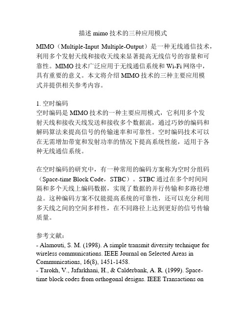
描述mimo技术的三种应用模式MIMO(Multiple-Input Multiple-Output)是一种无线通信技术,利用多个发射天线和接收天线来显著提高无线信号的容量和可靠性。
MIMO技术广泛应用于无线通信系统和Wi-Fi网络中,具有重要的意义。
本文将介绍MIMO技术的三种主要应用模式并提供相关参考内容。
1. 空时编码空时编码是MIMO技术的一种主要应用模式,它利用多个发射天线和接收天线发送和接收多个数据流,通过巧妙的编码和解码算法来提高信号的传输速率和可靠性。
空时编码技术可以在无需增加带宽和发射功率的情况下提高系统性能,适用于各种无线通信系统。
在空时编码的研究中,有一种常用的编码方案称为空时分组码(Space-time Block Code,STBC)。
STBC通过在多个时间间隔和多个天线上编码数据,实现了数据的并行传输和多路径增益。
这种编码方案不仅能提高系统的可靠性,还可以充分利用多天线之间的空间多样性,在不同路径上达到更好的信号传输质量。
参考文献:- Alamouti, S. M. (1998). A simple transmit diversity technique for wireless communications. IEEE Journal on Selected Areas in Communications, 16(8), 1451-1458.- Tarokh, V., Jafarkhani, H., & Calderbank, A. R. (1999). Space-time block codes from orthogonal designs. IEEE Transactions onInformation Theory, 45(5), 1456-1467.2. 多用户MIMO多用户MIMO是一种利用MIMO技术进行多用户通信的应用模式。
它可以同时传输多个用户的数据流,提高系统的容量和效率。
MIMO SYSTEMS

专利名称:MIMO SYSTEMS发明人:DAI, Linglong,GAO, Xinyu,WANG,Bichai,MACKENZIE, Richard,HAO, Mo 申请号:EP19769142.1申请日:20190913公开号:EP3864763A1公开日:20210818专利内容由知识产权出版社提供摘要:According to the present invention there is provided a multiple-input-multiple-output (MIMO) transmitter for transmitting wireless communication signals over a communication channel to a receiver, the transmitter comprising: a digital signal processor configured to perform pre-coding on a plurality of data streams; a plurality of radio-frequency (RF) chains each configured to pass a pre-coded data stream from the digital signal processor to generate a signal representing that data stream; a lens antenna array comprising an array of antenna elements; and a selecting unit coupled between the plurality of RF chains and the lens antenna array, the selecting unit comprising a plurality of separate coupling units each configured to couple a respective RF chain to a selective sub-array of (1) antenna elements concurrently for transmitting the signal representing the data stream passed through that RF chain.申请人:British Telecommunications public limited company地址:81 Newgate Street London EC1A 7AJ GB国籍:GB代理机构:British Telecommunications public limited company Intellectual PropertyDepartment更多信息请下载全文后查看。
MIMO无线通信系统中空分复用技术的研究的开题报告

MIMO无线通信系统中空分复用技术的研究的开题报告开题报告一、选题背景随着无线通信技术的不断发展,无线通信系统的数据传输速率和通信质量变得越来越重要。
在此背景下,MIMO(多输入多输出)无线通信技术应运而生,它利用多个天线同时发送和接收数据来提高无线通信的可靠性和效率。
MIMO技术的实现主要依赖于两个重要技术:空分复用(Spatial Division Multiplexing,SDM)和空时编码(Space Time Coding,STC)。
其中,空分复用技术是一种将多个数据流通过不同的发射天线分离传输的技术,可以将多个信号同时传输,提高信道覆盖范围和数据传输速率。
因此,空分复用技术广泛应用于MIMO无线通信系统中,成为提高通信性能的重要手段。
二、研究目的与意义空分复用技术在MIMO无线通信系统中的应用非常广泛,但是在实践中存在着一些问题,如:多天线的实现成本高昂、能量效率低等。
因此,为了更加深入地研究空分复用技术的应用,本文旨在对这方面的问题进行研究,并提出相应的解决措施。
此外,通过本文的研究,可以对MIMO无线通信系统的设计和实现提供参考,提高通信系统的传输效率和可靠性。
三、研究内容和方法本文的研究内容主要包括:1. MIMO无线通信系统的基本原理和技术;2. 空分复用技术的原理和应用;3. 空分复用技术在MIMO系统中的应用效果及其相关问题。
本文的研究方法主要采用文献综述和模拟仿真两种方法。
通过查阅现有文献,详细介绍MIMO无线通信系统的基本原理和技术,以及空分复用技术的原理和应用。
并通过仿真实验,对空分复用技术在MIMO系统中的应用效果进行评估,分析其应用存在的问题,从而提出相应的解决措施。
四、预期成果本文的预期成果主要包括:1. 对MIMO无线通信系统的基本原理和技术的深入了解;2. 对空分复用技术的原理和应用的深入了解;3. 评估空分复用技术在MIMO无线通信系统中的应用效果,并分析其存在的问题;4. 提出相应的解决措施,改善空分复用技术在MIMO系统中的应用效果;5. 对MIMO无线通信系统的研究和应用提供参考。
MIMO—新一代移动通信核心技术

MIMO——新一代移动通信核心技术摘要多入多出(MIMO:Multiple-Input Multiple-Output)技术对于传统的单天线系统来说,能够大大提高系统容量和频谱利用率,使得系统能在有限的无线频带下传输更高速率的数据业务。
本文简要介绍了无线通信中MIMO技术的发展现状、研究热点及应用。
关键词MIMO空时码BLAST OFDM从2001年12月NTT DoKoMo开始提供3G商用业务以来,一些国家也陆续准备部署3G网络。
与此同时,各国已开始或者计划新一代移动通信技术的研究,争取在未来移动通信领域内占有一席之地。
这里所提到的新一代移动通信是指后3G或者4G。
目前普遍认为后3G的最高传输速率将超过100M;能够实现全球无缝漫游,有非常高的灵活性,能自适应地进行资源分配;支持下一代internet(IPV6),而且是全IP网络,服务成本低也将是后3G的一个重要特征。
随着时势的发展,未来移动通信宽带无线移动和无线接入融合系统成为当前热门的研究课题,而MIMO(多进多出)系统是人们研究较多的方向之一。
1、MIMO技术的概念MIMO用于通信系统的概念早在20世纪70年代就有人提出,但是对无线移动通信系统MIMO技术产生巨大推动的奠基工作则是20世纪90年代由AT&T Bell实验室学者完成的。
1995年Teladar给出了在衰落情况下的MIMO容量;1996年Foshini给出了一种MIMO处理算法——D-BLAST(Diagonal-BLAST,对角BLAST)算法;1998年Tarokh等讨论了用于MIMO的空时码;1998年Wolinansky等采用V-BLAST(Vertical-BLAST,垂直BLAST)算法建立了一个MIMO 实验系统,在室内试验中达到了20bps/Hz以上的频谱利用率,这在普通系统中是极难实现的。
这些工作引起了各国学者的极大注意,并使得MIMO的研究得到了迅速发展。
- 1、下载文档前请自行甄别文档内容的完整性,平台不提供额外的编辑、内容补充、找答案等附加服务。
- 2、"仅部分预览"的文档,不可在线预览部分如存在完整性等问题,可反馈申请退款(可完整预览的文档不适用该条件!)。
- 3、如文档侵犯您的权益,请联系客服反馈,我们会尽快为您处理(人工客服工作时间:9:00-18:30)。
frmLen = 100; % frame lengthnumPackets = 1000; % number of packetsEbNo = 0:2:20; % Eb/No varying to 20 dBN = 2; % maximum number of Tx antennasM = 2; % maximum number of Rx antennasand set up the simulation.% Seed states for repeatabilityseed = [98765 12345]; randn('state', seed(1)); rand('state', seed(2));% Create BPSK mod-demod objectsP = 2; % modulation orderbpskmod = modem.pskmod('M', P, 'SymbolOrder', 'Gray');bpskdemod = modem.pskdemod(bpskmod);% Pre-allocate variables for speedtx2 = zeros(frmLen, N); H = zeros(frmLen, N, M);r21 = zeros(frmLen, 1); r12 = zeros(frmLen, 2);z21 = zeros(frmLen, 1); z21_1 = zeros(frmLen/N, 1); z21_2 = z21_1;z12 = zeros(frmLen, M);error11 = zeros(1, numPackets); BER11 = zeros(1, length(EbNo));error21 = error11; BER21 = BER11; error12 = error11; BER12 = BER11;% Set up a figure for visualizing BER resultsh = gcf; grid on; hold on;set(gca, 'yscale', 'log', 'xlim', [EbNo(1), EbNo(end)], 'ylim', [1e-5 1]); xlabel('Eb/No (dB)'); ylabel('BER'); set(h,'NumberTitle','off');set(h, 'renderer', 'zbuffer'); set(h,'Name','Transmit vs. Receive Diversity'); title('Transmit vs. Receive Diversity');% Loop over several EbNo pointsfor idx = 1:length(EbNo)% Loop over the number of packetsfor packetIdx = 1:numPacketsdata = randint(frmLen, 1, P); % data vector per user per channel tx = modulate(bpskmod, data); % BPSK modulation% Alamouti Space-Time Block Encoder, G2, full rate% G2 = [s1 s2; -s2* s1*]s1 = tx(1:N:end); s2 = tx(2:N:end);tx2(1:N:end, :) = [s1 s2];tx2(2:N:end, :) = [-conj(s2) conj(s1)];% Create the Rayleigh distributed channel response matrix% for two transmit and two receive antennasH(1:N:end, :, :) = (randn(frmLen/2, N, M) + ...j*randn(frmLen/2, N, M))/sqrt(2);% assume held constant for 2 symbol periodsH(2:N:end, :, :) = H(1:N:end, :, :);% Received signals% for uncoded 1x1 systemr11 = awgn(H(:, 1, 1).*tx, EbNo(idx));% for G2-coded 2x1 system - with normalized Tx power, i.e., the% total transmitted power is assumed constantr21 = awgn(sum(H(:, :, 1).*tx2, 2)/sqrt(N), EbNo(idx));% for Maximal-ratio combined 1x2 systemfor i = 1:Mr12(:, i) = awgn(H(:, 1, i).*tx, EbNo(idx));end% Front-end Combiners - assume channel response known at Rx% for G2-coded 2x1 systemhidx = 1:N:length(H);z21_1 = r21(1:N:end).* conj(H(hidx, 1, 1)) + ...conj(r21(2:N:end)).* H(hidx, 2, 1);z21_2 = r21(1:N:end).* conj(H(hidx, 2, 1)) - ...conj(r21(2:N:end)).* H(hidx, 1, 1);z21(1:N:end) = z21_1; z21(2:N:end) = z21_2;% for Maximal-ratio combined 1x2 systemfor i = 1:Mz12(:, i) = r12(:, i).* conj(H(:, 1, i));end% ML Detector (minimum Euclidean distance)demod11 = demodulate(bpskdemod, r11.*conj(H(:, 1, 1)));demod21 = demodulate(bpskdemod, z21);demod12 = demodulate(bpskdemod, sum(z12, 2));% Determine errorserror11(packetIdx) = biterr(demod11, data);error21(packetIdx) = biterr(demod21, data);error12(packetIdx) = biterr(demod12, data);end% end of FOR loop for numPackets% Calculate BER for current idx% for uncoded 1x1 systemBER11(idx) = sum(error11)/(numPackets*frmLen);% for G2 coded 2x1 systemBER21(idx) = sum(error21)/(numPackets*frmLen);% for Maximal-ratio combined 1x2 systemBER12(idx) = sum(error12)/(numPackets*frmLen);% Plot resultssemilogy(EbNo(1:idx), BER11(1:idx), 'r*', ...EbNo(1:idx), BER21(1:idx), 'go',...EbNo(1:idx), BER12(1:idx), 'bs');legend('No Diversity (1Tx, 1Rx)', 'Alamouti (2Tx, 1Rx)',...'Maximal-Ratio Combining (1Tx, 2Rx)');drawnow;end% end of for loop for EbNo% Perform curve fitting and replot the resultsfitBER11 = berfit(EbNo, BER11);fitBER21 = berfit(EbNo, BER21);fitBER12 = berfit(EbNo, BER12);semilogy(EbNo, fitBER11, 'r', EbNo, fitBER21, 'g', EbNo, fitBER12, 'b'); hold off;The transmit diversity system has a computation complexity very similar to that of the receive diversity system.The resulting simulation results show that using two transmit antennas and one receive antenna provides the same diversity order as the maximal-ratio combined (MRC) system of one transmit antenna and two receive antennas.Also observe that transmit diversity has a 3 dB disadvantage when compared to MRC receive diversity. This is because we modelled the total transmitted power to be the same in both cases. If we calibrate the transmitted power such that the received power for these two cases is the same, then the performance would be identical.The accompanying functional scripts, MRC1M.m and OSTBC2M.m aid further exploration for the interested users.PART 2: Space-Time Block Coding with Channel EstimationBuilding on the theory of orthogonal designs, Tarokh et al. [2] generalized Alamouti's transmit diversity scheme to an arbitrary number of transmitter antennas, leading to the concept of Space-Time Block Codes. For complex signal constellations, they showed that Alamouti's scheme is the only full-rate scheme for two transmit antennas.In this section, we study the performance of such a scheme with two receive antennas (i.e., a 2x2 system) with and without channel estimation. In the realistic scenario where the channel state information is not known at the receiver, this has to be extracted from the received signal. We assume that the channel estimator performs this using orthogonal pilot signals that are prepended to every packet [3]. It is assumed that the channel remains unchanged for the length of the packet (i.e.,it undergoes slow fading).A simulation similar to the one described in the previous section is employed here, which leads us to estimate the BER performance for a space-time block codedsystem using two transmit and two receive antennas.Again we start by defining the common simulation parametersfrmLen = 100; % frame lengthmaxNumErrs = 300; % maximum number of errorsmaxNumPackets = 3000; % maximum number of packetsEbNo = 0:2:12; % Eb/No varying to 12 dBN = 2; % number of Tx antennasM = 2; % number of Rx antennaspLen = 8; % number of pilot symbols per frameW = hadamard(pLen);pilots = W(:, 1:N); % orthogonal set per transmit antennaand set up the simulation.% Seed states for repeatabilityseed = [98765 12345]; randn('state', seed(1)); rand('state', seed(2));% Pre-allocate variables for speedtx2 = zeros(frmLen, N); r = zeros(pLen + frmLen, M);H = zeros(pLen + frmLen, N, M); H_e = zeros(frmLen, N, M);z_e = zeros(frmLen, M); z1_e = zeros(frmLen/N, M); z2_e = z1_e;z = z_e; z1 = z1_e; z2 = z2_e;BER22_e = zeros(1, length(EbNo)); BER22 = BER22_e;% Set up a figure for visualizing BER resultsclf(h); grid on; hold on;set(gca,'yscale','log','xlim',[EbNo(1), EbNo(end)],'ylim',[1e-5 1]);xlabel('Eb/No (dB)'); ylabel('BER'); set(h,'NumberTitle','off');set(h,'Name','Orthogonal Space-Time Block Coding');set(h, 'renderer', 'zbuffer'); title('G2-coded 2x2 System');% Loop over several EbNo pointsfor idx = 1:length(EbNo)numPackets = 0; totNumErr22 = 0; totNumErr22_e = 0;% Loop till the number of errors exceed 'maxNumErrs'% or the maximum number of packets have been simulatedwhile (totNumErr22 < maxNumErrs) && (totNumErr22_e < maxNumErrs) && ... (numPackets < maxNumPackets)data = randint(frmLen, 1, P); % data vector per user per channel tx = modulate(bpskmod, data); % BPSK modulation% Alamouti Space-Time Block Encoder, G2, full rate% G2 = [s1 s2; -s2* s1*]s1 = tx(1:N:end); s2 = tx(2:N:end);tx2(1:N:end, :) = [s1 s2];tx2(2:N:end, :) = [-conj(s2) conj(s1)];% Prepend pilot symbols for each frametransmit = [pilots; tx2];% Create the Rayleigh distributed channel response matrixH(1, :, :) = (randn(N, M) + j*randn(N, M))/sqrt(2);% assume held constant for the whole frame and pilot symbolsH = H(ones(pLen + frmLen, 1), :, :);% Received signal for each Rx antenna% with pilot symbols transmittedfor i = 1:M% with normalized Tx powerr(:, i) = awgn(sum(H(:, :, i).*transmit, 2)/sqrt(N), EbNo(idx));end% Channel Estimation% For each link => N*M estimatesfor n = 1:NH_e(1, n, :) = (r(1:pLen, :).' * pilots(:, n))./pLen;end% assume held constant for the whole frameH_e = H_e(ones(frmLen, 1), :, :);% Combiner using estimated channelheidx = 1:N:length(H_e);for i = 1:Mz1_e(:, i) = r(pLen+1:N:end, i).* conj(H_e(heidx, 1, i)) + ... conj(r(pLen+2:N:end, i)).* H_e(heidx, 2, i);z2_e(:, i) = r(pLen+1:N:end, i).* conj(H_e(heidx, 2, i)) - ... conj(r(pLen+2:N:end, i)).* H_e(heidx, 1, i);endz_e(1:N:end, :) = z1_e; z_e(2:N:end, :) = z2_e;% Combiner using known channelhidx = pLen+1:N:length(H);for i = 1:Mz1(:, i) = r(pLen+1:N:end, i).* conj(H(hidx, 1, i)) + ...conj(r(pLen+2:N:end, i)).* H(hidx, 2, i);z2(:, i) = r(pLen+1:N:end, i).* conj(H(hidx, 2, i)) - ...conj(r(pLen+2:N:end, i)).* H(hidx, 1, i);endz(1:N:end, :) = z1; z(2:N:end, :) = z2;% ML Detector (minimum Euclidean distance)demod22_e = demodulate(bpskdemod, sum(z_e, 2)); % estimateddemod22 = demodulate(bpskdemod, sum(z, 2)); % known% Determine errorsnumPackets = numPackets + 1;totNumErr22_e = totNumErr22_e + biterr(demod22_e, data);totNumErr22 = totNumErr22 + biterr(demod22, data);end% end of FOR loop for numPackets% Calculate BER for current idx% for estimated channelBER22_e(idx) = totNumErr22_e/(numPackets*frmLen);% for known channelBER22(idx) = totNumErr22/(numPackets*frmLen);% Plot resultssemilogy(EbNo(1:idx), BER22_e(1:idx), 'ro');semilogy(EbNo(1:idx), BER22(1:idx), 'g*');legend(['Channel estimated with ' num2str(pLen) ' pilot symbols/frame'],...'Known channel');drawnow;end% end of for loop for EbNo% Perform curve fitting and replot the resultsfitBER22_e = berfit(EbNo, BER22_e);fitBER22 = berfit(EbNo, BER22);semilogy(EbNo, fitBER22_e, 'r', EbNo, fitBER22, 'g'); hold off;For the 2x2 simulated system, the diversity order is different than that seen foreither 1x2 or 2x1 systems in the previous section.Note that with 8 pilot symbols for each 100 symbols of data, channel estimationcauses about a 1 dB degradation in performance for the selected Eb/No range. This improves with an increase in the number of pilot symbols per frame but adds to the overhead of the link. In this comparison, we keep the transmitted SNR per symbolto be the same in both cases.The accompanying functional script, OSTBC2M_E.m aids further experimentationfor the interested users.PART 3: Orthogonal Space-Time Block Coding and Further ExplorationsIn this final section, we present some performance results for orthogonal space-timeblock coding using four transmit antennas (4x1 system) using a half-rate code, G4,as per [4].We expect the system to offer a diversity order of 4 and will compare it with 1x4 and2x2 systems, which have the same diversity order also. To allow for a faircomparison, we use quaternary PSK with the half-rate G4 code to achieve the same transmission rate of 1 bit/sec/Hz.Since these results take some time to generate, we load the results from a prior simulation. The functional script OSTBC4M.m is included, which, along withMRC1M.m and OSTBC2M.m, was used to generate these results. The user isurged to use these scripts as a starting point to study other codes and systems.load ostbcRes.mat;% Set up a figure for visualizing BER resultsclf(h); grid on; hold on; set(h, 'renderer', 'zbuffer');set(gca, 'yscale', 'log', 'xlim', [EbNo(1), EbNo(end)], 'ylim', [1e-5 1]);xlabel('Eb/No (dB)'); ylabel('BER'); set(h,'NumberTitle','off');set(h,'Name','Orthogonal Space-Time Block Coding(2)');title('G4-coded 4x1 System and Other Comparisons');% Plot resultssemilogy(EbNo, ber11, 'r*', EbNo, ber41, 'ms', EbNo, ber22, 'c^', ...EbNo, ber14, 'ko');legend('No Diversity (1Tx, 1Rx), BPSK', 'OSTBC (4Tx, 1Rx), QPSK', ...'Alamouti (2Tx, 2Rx), BPSK', 'Maximal-Ratio Combining (1Tx, 4Rx), BPSK'); % Perform curve fittingfitBER11 = berfit(EbNo, ber11);fitBER41 = berfit(EbNo(1:9), ber41(1:9));fitBER22 = berfit(EbNo(1:8), ber22(1:8));fitBER14 = berfit(EbNo(1:7), ber14(1:7));semilogy(EbNo, fitBER11, 'r', EbNo(1:9), fitBER41, 'm', ...EbNo(1:8), fitBER22, 'c', EbNo(1:7), fitBER14, 'k'); hold off;As expected, the similar slopes of the BER curves for the 4x1, 2x2 and 1x4 systems indicate an identical diversity order for each system.Also observe the 3 dB penalty for the 4x1 system that can be attributed to the same total transmitted power assumption made for each of the three systems. If we calibrate the transmitted power such that the received power for each of these systems is the same, then the three systems would perform identically.References:[1] S. M. Alamouti, "A simple transmit diversity technique for wirelesscommunications", IEEE Journal on Selected Areas in Communications,Vol. 16, No. 8, Oct. 1998, pp. 1451-1458.[2] V. Tarokh, H. Jafarkhami, and A.R. Calderbank, "Space-time block codes from orthogonal designs", IEEE Transactions on Information Theory,Vol. 45, No. 5, Jul. 1999, pp. 1456-1467.[3] A.F. Naguib, V. Tarokh, N. Seshadri, and A.R. Calderbank, "Space-time codes for high data rate wireless communication: Mismatch analysis", Proceedings of IEEE International Conf. on Communications,pp. 309-313, June 1997.[4] V. Tarokh, H. Jafarkhami, and A.R. Calderbank, "Space-time block codes for wireless communications: Performance results", IEEE Journal onSelected Areas in Communications, Vol. 17, No. 3, Mar. 1999,pp. 451-460.Copyright 2006 The MathWorks, Inc.Published with MATLAB® 7.4。