UCS1912说明书
奥美晨曦系列微波传感器说明书
OS100 SERIES Mini-Infrared Transmitter e-mail:**************For latest product manuals: Shop online at User’s G ui d e***********************Servicing North America:U.S.A. Omega Engineering, Inc.Headquarters: Toll-Free: 1-800-826-6342 (USA & Canada only)Customer Service: 1-800-622-2378 (USA & Canada only)Engineering Service: 1-800-872-9436 (USA & Canada only)Tel: (203) 359-1660 Fax: (203) 359-7700e-mail:**************For Other Locations Visit /worldwideThe information contained in this document is believed to be correct, but OMEGA accepts no liability for any errors it contains, and reserves the right to alter specifications without notice.Table of ContentsSection ...................................................................PageSafety Warnings and IEC Symbols (iii)Caution and Safety Information (iii)Section 1 Introduction ....................................................................1-1Section 2Installation ......................................................................1-12.1 Unpacking and Inspection ......................................1-12.2 Electrical Connection ..............................................2-1Section 3Operation ........................................................................3-13.1 Main Board ................................................................3-13.2 Ambient Temperature ..............................................3-23.3 Atmospheric Quality ................................................3-33.4 Measuring Temperature ..........................................3-33.5 Alarm Setting ............................................................3-43.6 Adding Extension Cable...........................................3-4Section 4 Laser Sight Accessory ...................................................4-14.1 Warning and Cautions .............................................4-14.2 Operating the Laser Sight Accessory .....................4-1Section 5 Specifications .................................................................5-15.1 General .......................................................................5-15.2 Laser Sight Accessory (OS100-LS) ..........................5-2Section 6Emissivity Table .............................................................6-1iTable of FiguresFigure Description Page2-1Power Supply & Analog Output Connections ..........2-12-2 Alarm Output Connection ............................................2-13-1 Main PC Board ...............................................................3-23-2 Sensor..............................................................3-2Housing3-3 Optical Field of View .....................................................3-43-4Setting the Temperature Engineering Unit..................3-43-5Mounting Bracket OS100-MB .......................................3-53-6Water Cooling Jacket, OS100-WC ................................3-53-7Typical Water Cool Jacket Assembly ...........................3-53-8Air Purge Collar, OS100-AP..........................................3-63-9DIN Rail Mounting Adapter, OS100-DR ....................3-63-10NEMA-4 Aluminum Enclosure ....................................3-64-1Laser Sighting Accessory, OS100-LS ............................4-24-2Laser Warning Label ......................................................4-2iiSafety Warnings and IEC SymbolsThis device is marked with international safety and hazard symbols in accordance with IEC 1010. It is important to read and follow all precautions and instructions in this manual before operating or commissioning this device as it contains important information relating to safety and EMC. Failure to follow all safety precautions may result in injury and or damage to your calibrator. IEC symbols DescriptionCaution and Safety Information• If the equipment is used in a manner not specified in this manual, the protection provided by the equipment may be impaired.• The installation category is one (1).• There are no user replaceable fuses in this product• The output terminals of this product are for use with equipment (digital meters, chart recorders, etc,) which have no accessible five parts. Such equipment should comply with all the applicable safety requirements.• Do not operate the equipment in flammable or explosive environments.• All connections to the thermometer should be made via a shielded cable, 24 AWG stranded wire with the following ratings: 300V , 105°C (221°F), PVC insulation.• Power must be disconnected before making any electrical connections.• The power supply used to power the thermometer should be VDE or UL approved with the following ratings: 12 to 24vdc @150mA with overload protection of 500mA.iiiCaution, refer to accompanying documentsDirect Current Laser SymbolFrame or ChassisNOTES: ivSection 1 - IntroductionThe low cost OS101 mini-infrared transmitter provides non-contacttemperature measurement for industrial applications. The unit measures atemperature range of -18 to 538°C (0-1000°F) and provides a linear analogoutput of either 4-20 mA, 0-5 VDC, K type TC, 1 mV/°C, or 1 mV/°F.The new OS102 mini-infrared transmitter has all the functions of OS101plus a built-in LED display that shows the measured temperature indegrees F or degrees C which is switchable in the field.The miniature sensor head design 2.5 cm dia. x 6.3 cm Length (1" x 2.5") isideal for measuring temperature in confined, and hard to reach places.The aluminum sensor head as well as the rugged electronic housing (Diecast Aluminum) are NEMA-4 rated.The sensor head is connected to the electronic housing via a 1.82 m (6 feet)shielded cable as standard. The unit provides field adjustable alarmoutput.Section 2 - Installation2.1UnpackingRemove the packing list and verify that you have received all yourequipment. If you have any questions about the shipment, please callCustomer Service at:1-800-622-2378 or 203-359-1660. We can also be reached on the internet:e-mail:**************When you receive the shipment, inspect the container and equipment forany signs of damage. Note any evidence of rough handling in transit.inspection. After examination and removing contents, save packing material and carton in theevent reshipment is necessary.The following items are supplied in the box:• The infrared transmitter including the sensor head and the 1.82 m(6 feet) shielded cable• User's Manual• Mounting Nut1-1The following describes the ordering information:OS102 or OS101 - MA- *,**, where The following optional accessories are available:Here are the Features of OS101 and OS102 infrared transmitters:2.2Electrical Connection Sensor Head Cable - The Sensor head is pre-wired to a 1.8 m (6 feet)shielded cable. Plug & lock-in the male connector to the mating female connector on the aluminum housing.Power & Output Connection - Open the cover of the main aluminum housing. Slide the cable through the strain relief and connect the wires to the terminal block on the board as shown in Fig. 2-1. For Alarm output connection, refer to Fig. 2-2.2-1MA - 4/20 mA output V1 - 0 to 5 VDC output K - Thermocouple output, K type MV - Millivolt output C - 1 mV/°C output F - 1 mV/°F output HT- High temperature sensor head3-1Figure 2-2. Alarm Output Connection Section 3 - Operation3-1Main BoardThe Main Board is shown in Fig. 3-1. Here are the important components on the board:(1) - Terminal Block for Power & Output connections(2) - Single Turn Potentiometer to adjust Emissivity in tenths (0.x_)(3) - Single Turn Potentiometer to adjust Emissivity in hundreds (0._x)(4) -Slide switch to select between real time (Normal Operation) and alarm set point(5) - Alarm set point adjust, P4(6) - Sensor Head connection(7) - Input Zero adjust, P3(8) - Input Span adjust, P2(9) - Output Zero adjust, P5(10) - Output Span adjust, P6Figure 3-1. Main PC Board3.2Ambient TemperatureThe Sensing head can operate in an ambient temperature of 0 to 70°C (32to 158°F). The Sensing head in the high temperature model (-HT) can operate in an ambient temperature of 0 to 85°C (32 to 185°F) without any cooling required. The Sensing head can operate up to 200°C (392°F) using the water cool jacket accessory OS100-WC (See Fig. 3-6).There is a warm up period of 3 minutes after power up. After the warm up period, temperature measurement can be made.When the ambient temperature around the sensor head changes abruptly,the sensor head goes through thermal shock. It takes a certain amount of time for the sensor head to stabilize to the new ambient temperature. For example, it takes about 30 minutes for the sensor head to stabilize going from 25°C to 50°C (77 to 122°F) ambient temperature.The sensor head dimensions are shown in Fig. 3-2.Figure 3-2. Sensor Housing3-23-33.3Atmospheric QualityEnvironments with smoke, dust, and fumes dirty up the optical lens, and cause erroneous temperature readings. To keep the surface of the optical lens clean, the air purge collar accessory is recommended, OS100-AP , See Fig. 3-7.3.4Measuring TemperatureBefore starting to measure temperature, make sure that the following check list is met:ߜ The power and analog output connections are made (Fig. 2-1).ߜThe sensor head is connected to the main unit.ߜThe slide switch (SW1) on the main board is set to real time (Fig. 3-1).ߜThe target is larger than the optical field of view of the sensor head (Fig. 3-3).ߜThe emissivity adjustment on the main board is set properly (Fig. 3-1).ߜThe output load is within the product specification.On OS102 transmitters, follow these additional steps:ߜ The temperature display is set to °F or °C (Fig. 3-4)ߜ For 4-20mA output models, make sure an output load is added, ie. 250ohms.Figure 3-3. Optical Field Of ViewFigure 3-4. Setting the Temperature Engineering Unit3.5Alarm SettingThe unit provides 0-100% alarm set point adjustment. Here is an exampleof an alarm setting.• An OS101-MA(4/20 mA output), the alarm is to be set at 400°Ftemperature.• Connect the alarm output as shown in Fig. 2-2.• Set the slide switch (SW1) on the main board to the Alarm position.• Measure the analog output, and set the Potentiometer P4 until theoutput reads 10.4 mA which is 40% (400°F) of the temperature range.40 x (20-4)[10.4mA=+ 4]100• Set the slide switch (SW1) back to the Real Time position.• If the temperature reading is below the alarm set point, the alarmoutput stays high, otherwise it goes low.On the OS102, you can set the alarm set point directly based on thetemperature display.3.6Adding Extension CableYou can add extension cable between the Sensor Head and the mainelectronic housing up to 15.2 m (50 feet). After adding the extension cable,the Zero input potentiometer, P3 may be re-adjusted. (See Fig. 3-1, forproper analog output reading)The following figures show the mounting bracket (OS100-MB), Watercooling jacket (OS100-WC), Air purge collar (OS100-AP), DIN RailMounting adapter (OS-100-DR), and the main aluminum enclosure. TheDIN Rail Mounting adapter (OS100-DR) is mounted to the bottom of themain aluminum enclosure using two 4-40 screws.A typical water cool jacket assembly is shown in Fig. 3-7, on the following page.1. Mounting Nut2. Mounting Bracket3. Water Cool Jacket4. Sensor Head3-4Figure 3-5. Mounting Bracket OS100-MBFigure 3-6. Water Cooling Jacket, OS100-WCFigure 3-7. Typical Water Cool Jacket Assembly3-5Figure 3-8. Air Purge Collar, OS100-APFigure 3-9. DIN Rail Mounting Adapter, OS-100-DRFigure 3-10. NEMA-4 Aluminum Enclosure3-6Section 4 - Laser Sight Accessory4.1Warning and Cautionsbelow:•Use of controls or adjustments or performance of procedures other than those specified here may result in hazardous radiation exposure.• Do not look at the laser beam coming out of the lens or view directly with optical instruments - eye damage can result.• Use extreme caution when operation the laser sight accessory • Never point the laser accessory at a person • Keep out of the reach of all children4.2Operating the Laser Sight AccessoryThe laser sight accessory screws onto the front of the sensor head. This accessory is only used for alignment of the sensor head to the target area.After the alignment process, the accessory has to be removed from the front of the sensor head before temperature measurement.The laser sight accessory is powered from a small compact battery pack (included with the accessory). Connect the battery pack to the accessory using the cable provided. Aim at the target, and turn on the battery power using the slide switch on the battery pack. Adjust the sensor head position so that the laser beam points to the center of the target area. Turn off the battery pack, and remove the laser sighting accessory from the sensor head. See Fig. 4-1 for reference.4-14-2Figure 4-2. Laser Warning LabelSection 5 - Specifications5.1 - GeneralTemperature Range-18 to 538°C (0 to 1000°F)Accuracy @ 22°C (72°F)±2% of Rdg. or 2.2°C (4°F) whichever is ambient temperature & greateremissivity of 0.95 or greaterOptical Field of View6:1 (Distance/Spot Size)Repeatability±1% of Rdg.Spectral Response 5 to 14 micronsResponse Time150 msec (0 to 63% of final value)Emissivity Range0.1 to 0.99, adjustableOperating Ambient TemperatureMain Transmitter0 to 50°C (32 to 122°F)Sensor Head0 to 70°C (32 to 158°F)Sensor Head (-HT Model)0 to 85°C (32 to 185°F)Sensor Head with OS100-WC(Water Cooling Jacket)0 to 200°C (32 to 392°F)Operating Relative Humidity Less than 95% RH, non-condensingWater Flow Rate for OS100-WC0.25 GPM, room temperatureThermal Shock About 30 minutes for 25°Cabrupt ambient temperature change Warm Up Period 3 minutesAir Flow Rate for OS100-AP 1 CFM (0.5 Liters/sec.)Power12 to 24 VDC @ 100 mAAnalog OutputsMV-F 1 mV/°FMV-C 1 mV/°CK K Type TC - OS101 onlyMA 4 to 20 mAV10 to 5 VDCOutput Load requirementsMin. Load (0 to 5VDC) 1 K-OhmsMax. Load (4 to 20 mA)(Supply Power - 4 )/20 mATransmitter Housing NEMA-4 & IP65, Die Cast AluminumSensor Head Housing NEMA-4 , AluminumAlarm Output Open Drain, 100 mAAlarm Set Point0 to 100% , Adjustable via P4Alarm Deadband14°C (25°F)5-15-25.1 - General Con’t.DimensionsSensor Head25.4 OD. x 63.5 mm L(1" OD. x 2.5" L)Main Housing, OS10165.5 W x 30.5 H x 115.3 mm L(2.58" W x 1.2" H x 4.54" L)Main Housing, OS10265.5 W x 55.9 H x 115.3 mm L(2.58" W x 2.2" H x 4.54" L)Weight 272 g (0.6 lb)5.2Laser Sight Accessory (OS100-LS)Wavelength (Color)630 - 670 nm (Red)Operating Distance (Laser Dot)Up to 9.1 m (30 ft.)Max. Output Optical Power Less than 1 mW at 22°F ambienttemperature.European Classification Class 2, EN60825-1/11.2001Maximum Operating current45 mA at 3 VDCFDA Classification Complies with 21 CFR 1040.10,Class II Laser ProductBeam Diameter 5 mmBeam Divergence< 2 mradOperating Temperature0 to 50°C (32 to 122°F)Operating Relative Humidity Less than 95% RH, non-condensingPower Switch ON / OFF , Slide switch on the BatteryPackPower Indicator Red LEDPower Battery Pack, 3 VDC (Consists of two 1.5VDC AA size Lithium Batteries) Laser Warning Label Located on the head sight circumferenceIdentification Label Located on the head sight circumferenceDimensions38 DIA x 50.8 mm L(1.5" DIA x 2" L)Section 6 - Emissivity Table6-1Material Emissivity (ε)Aluminum – pure highly polished plate . . . . . . . . . . . . . . . . . . . . . . . . 0.04 to 0.06Aluminum – heavily oxidized . . . . . . . . . . . . . . . . . . . . . . . . . . . . . . . 0.20 to 0.31Aluminum – commercial sheet . . . . . . . . . . . . . . . . . . . . . . . . . . . . . . . . . . . . 0.09Brass – dull plate. . . . . . . . . . . . . . . . . . . . . . . . . . . . . . . . . . . . . . . . . . . . . . 0.22Brass – highly polished, 73.2% Cu, 26.7% Zn. . . . . . . . . . . . . . . . . . . . . . . . . 0.03Chromium – polished. . . . . . . . . . . . . . . . . . . . . . . . . . . . . . . . . . . . . 0.08 to 0.36Copper – polished. . . . . . . . . . . . . . . . . . . . . . . . . . . . . . . . . . . . . . . . . . . . . 0.05Copper – heated at 600°C (1112°F). . . . . . . . . . . . . . . . . . . . . . . . . . . . . . . 0.57Gold – pure, highly polished or liquid. . . . . . . . . . . . . . . . . . . . . . . . . 0.02 to 0.04Iron and steel (excluding stainless)– polished iron . . . . . . . . . . . . . . . . 0.14 to 0.38Iron and steel (excluding stainless)– polished cast iron. . . . . . . . . . . . . . . . . . . 0.21Iron and steel (excluding stainless)– polished wrought iron . . . . . . . . . . . . . . . 0.28Iron and steel (excluding stainless)– oxidized dull wrought iron . . . . . . . . . . . . 0.94Iron and steel (excluding stainless)– rusted iron plate . . . . . . . . . . . . . . . . . . . 0.69Iron and steel (excluding stainless)– polished steel. . . . . . . . . . . . . . . . . . . . . . 0.07Iron and steel (excluding stainless)– polished steel oxidized at600°C (1112°F). . . . . . . . . . . . . . . . . . . . 0.79Iron and steel (excluding stainless)– rolled sheet steel . . . . . . . . . . . . . . . . . . . 0.66Iron and steel (excluding stainless)– rough steel plate . . . . . . . . . . . . . 0.94 to 0.97Lead – gray and oxidized . . . . . . . . . . . . . . . . . . . . . . . . . . . . . . . . . . . . . . . 0.28Mercury . . . . . . . . . . . . . . . . . . . . . . . . . . . . . . . . . . . . . . . . . . . . . 0.09 to 0.12Molybdenum filament . . . . . . . . . . . . . . . . . . . . . . . . . . . . . . . . . . . . 0.10 to 0.20Nickel – polished . . . . . . . . . . . . . . . . . . . . . . . . . . . . . . . . . . . . . . . . . . . . . 0.07Nickel – oxidized at 649 to 1254°C (1200°F to 2290°F). . . . . . . . . . . 0.59 to 0.86Platinum – pure polished plate . . . . . . . . . . . . . . . . . . . . . . . . . . . . . . 0.05 to 0.10Platinum – wire . . . . . . . . . . . . . . . . . . . . . . . . . . . . . . . . . . . . . . . . 0.07 to 0.18Silver – pure and polished . . . . . . . . . . . . . . . . . . . . . . . . . . . . . . . . . 0.02 to 0.03Stainless steel – polished . . . . . . . . . . . . . . . . . . . . . . . . . . . . . . . . . . . . . . . . 0.07Stainless steel – Type 301 at 232 to 942°C (450°F to 1725°F). . . . . . . 0.54 to 0.63Tin – bright . . . . . . . . . . . . . . . . . . . . . . . . . . . . . . . . . . . . . . . . . . . . . . . . . 0.06Tungsten – filament . . . . . . . . . . . . . . . . . . . . . . . . . . . . . . . . . . . . . . . . . . . . 0.39Zinc – polished commercial pure . . . . . . . . . . . . . . . . . . . . . . . . . . . . . . . . . . 0.05Zinc – galvanized sheet. . . . . . . . . . . . . . . . . . . . . . . . . . . . . . . . . . . . . . . . . 0.23M E T A L S6-2Material Emissivity (ε) Asbestos Board . . . . . . . . . . . . . . . . . . . . . . . . . . . . . . . . . . . . . . . . . . . . . . .0.96 Asphalt, tar, pitch . . . . . . . . . . . . . . . . . . . . . . . . . . . . . . . . . . . . . . .0.95 to 1.00 Brick– red and rough . . . . . . . . . . . . . . . . . . . . . . . . . . . . . . . . . . . . . . . . . .0.93 Brick– fireclay . . . . . . . . . . . . . . . . . . . . . . . . . . . . . . . . . . . . . . . . . . . . . . .0.75 Carbon– filament . . . . . . . . . . . . . . . . . . . . . . . . . . . . . . . . . . . . . . . . . . . . .0.53 Carbon– lampblack - rough deposit . . . . . . . . . . . . . . . . . . . . . . . . . .0.78 to 0.84 Glass- Pyrex, lead, soda . . . . . . . . . . . . . . . . . . . . . . . . . . . . . . . . . .0.85 to 0.95 Marble– polished light gray . . . . . . . . . . . . . . . . . . . . . . . . . . . . . . . . . . . . .0.93 Paints, lacquers, and varnishes– Black matte shellac . . . . . . . . . . . . . . . . . . . .0.91 Paints, lacquers, and varnishes– aluminum paints . . . . . . . . . . . . . . . .0.27 to 0.67 Paints, lacquers, and varnishes– flat black lacquer . . . . . . . . . . . . . . .0.96 to 0.98 Paints, lacquers, and varnishes– white enamel varnish . . . . . . . . . . . . . . . . . .0.91 Porcelain– glazed . . . . . . . . . . . . . . . . . . . . . . . . . . . . . . . . . . . . . . . . . . . . .0.92 Quartz– opaque . . . . . . . . . . . . . . . . . . . . . . . . . . . . . . . . . . . . . . . .0.68 to 0.92 Roofing Paper . . . . . . . . . . . . . . . . . . . . . . . . . . . . . . . . . . . . . . . . . . . . . . .0.91 Tape– Masking . . . . . . . . . . . . . . . . . . . . . . . . . . . . . . . . . . . . . . . . . . . . . .0.95 Water . . . . . . . . . . . . . . . . . . . . . . . . . . . . . . . . . . . . . . . . . . . . . . . .0.95 to 0.96 Wood– planed oak . . . . . . . . . . . . . . . . . . . . . . . . . . . . . . . . . . . . . . . . . . . .0.90 NONMETALSNOTES:6-3NOTES: 6-4OMEGA’s policy is to make running changes, not model changes, whenever an improvement is possible. T his affords our customers the latest in technology and engineering.OMEGA is a trademark of OMEGA ENGINEERING, INC.© Copyright 2017 OMEGA ENGINEERING, INC. All rights reserved. T his document may not be copied, photocopied, reproduced, translated, or reduced to any electronic medium or machine-readable form, in whole or in part, without the prior written consent of OMEGA ENGINEERING, INC.FOR WARRANTY RETURNS, please have the following information available BEFORE contacting OMEGA:1. P urchase Order number under which the product was PURCHASED,2. M odel and serial number of the product under warranty, and3. Repair instructions and/or specific problems relative to the product.FOR NON-WARRANTY REPAIRS, consult OMEGA for current repair charges. Have the following information available BEFORE contacting OMEGA:1. Purchase Order number to cover the COST of the repair,2. Model and serial number of the product, and 3. Repair instructions and/or specific problems relative to the product.RETURN REQUESTS/INQUIRIESDirect all warranty and repair requests/inquiries to the OMEGA Customer Service Department. BEFORE RET URNING ANY PRODUCT (S) T O OMEGA, PURCHASER MUST OBT AIN AN AUT HORIZED RET URN (AR) NUMBER FROM OMEGA’S CUST OMER SERVICE DEPART MENT (IN ORDER T O AVOID PROCESSING DELAYS). The assigned AR number should then be marked on the outside of the return package and on any correspondence.T he purchaser is responsible for shipping charges, freight, insurance and proper packaging to preventbreakage in transit.WARRANTY/DISCLAIMEROMEGA ENGINEERING, INC. warrants this unit to be free of defects in materials and workmanship for a period of 25 months from date of purchase. OMEGA’s WARRANTY adds an additional one (1) month grace period to the normal two (2) year product warranty to cover handling and shipping time. This ensures that OMEGA’s customers receive maximum coverage on each product.If the unit malfunctions, it must be returned to the factory for evaluation. OMEGA’s Customer Service Department will issue an Authorized Return (AR) number immediately upon phone or written request. Upon examination by OMEGA, if the unit is found to be defective, it will be repaired or replaced at no charge. OMEGA’s WARRANT Y does not apply to defects resulting from any action of the purchaser, including but not limited to mishandling, improper interfacing, operation outside of design limits, improper repair, or unauthorized modification. T his WARRANT Y is VOID if the unit shows evidence of having been tampered with or shows evidence of having been damaged as a result of excessive corrosion; or current, heat, moisture or vibration; improper specification; misapplication; misuse or other operating conditions outside of OMEGA’s control. Components in which wear is not warranted, include but are not limited to contact points, fuses, and triacs.OMEGA is pleased to offer suggestions on the use of its various products. However, OMEGA neither assumes responsibility for any omissions or errors nor assumes liability for any damages that result from the use of its products in accordance with information provided by OMEGA, either verbal or written. OMEGA warrants only that the parts manufactured by the company will be as specified and free of defects. OMEGA MAKES NO OTHER WARRANTIES OR REPRESENTATIONS OF ANY KIND WHATSOEVER, EXPRESSED OR IMPLIED, EXCEPT THAT OF TITLE, AND ALL IMPLIED W ARRANTIES INCLUDING ANY W ARRANTY OF MERCHANTABILITY AND FITNESS FOR A PARTICULAR PURPOSE ARE HEREBY DISCLAIMED. LIMITATION OF LIABILITY: The remedies of purchaser set forth herein are exclusive, and the total liability of OMEGA with respect to this order, whether based on contract, warranty, negligence, indemnification, strict liability or otherwise, shall not exceed the purchase price of the component upon which liability is based. In no event shall OMEGA be liable for consequential, incidental or special damages.CONDITIONS: Equipment sold by OMEGA is not intended to be used, nor shall it be used: (1) as a “Basic Component” under 10 CFR 21 (NRC), used in or with any nuclear installation or activity; or (2) in medical applications or used on humans. Should any Product(s) be used in or with any nuclear installation or activity, medical application, used on humans, or misused in any way, OMEGA assumes no responsibility as set forth in our basic WARRANT Y /DISCLAIMER language, and, additionally, purchaser will indemnify OMEGA and hold OMEGA harmless from any liability or damage whatsoever arising out of the use of theProduct(s) in such a manner.Where Do I Find Everything I Need forProcess Measurement and Control?OMEGA…Of Course!Shop online at TEMPERATUREM U Thermocouple, RTD & Thermistor Probes, Connectors,Panels & AssembliesM U Wire: Thermocouple, RTD & ThermistorM U Calibrators & Ice Point ReferencesM U Recorders, Controllers & Process MonitorsM U Infrared PyrometersPRESSURE, STRAIN AND FORCEM U Transducers & Strain GagesM U Load Cells & Pressure GagesM U Displacement TransducersM U Instrumentation & AccessoriesFLOW/LEVELM U Rotameters, Gas Mass Flowmeters & Flow ComputersM U Air Velocity IndicatorsM U Turbine/Paddlewheel SystemsM U Totalizers & Batch ControllerspH/CONDUCTIVITYM U pH Electrodes, Testers & AccessoriesM U Benchtop/Laboratory MetersM U Controllers, Calibrators, Simulators & PumpsM U Industrial pH & Conductivity EquipmentDATA ACQUISITIONM U Communications-Based Acquisition SystemsM U Data Logging SystemsM U Wireless Sensors, Transmitters, & ReceiversM U Signal ConditionersM U Data Acquisition SoftwareHEATERSM U Heating CableM U Cartridge & Strip HeatersM U Immersion & Band HeatersM U Flexible HeatersM U Laboratory HeatersENVIRONMENTALMONITORING AND CONTROLM U Metering & Control InstrumentationM U RefractometersM U Pumps & TubingM U Air, Soil & Water MonitorsM U Industrial Water & Wastewater TreatmentM U pH, Conductivity & Dissolved Oxygen InstrumentsM3572/1217。
C8控制器使用说明书
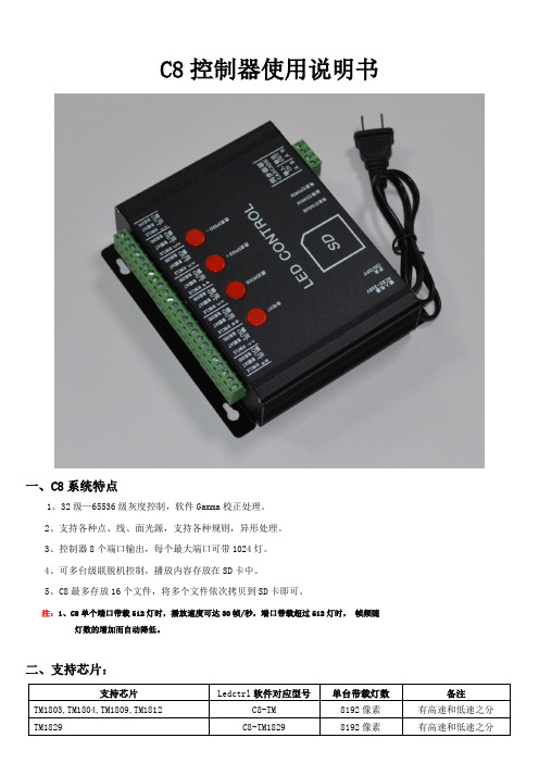
C8控制器使用说明书一、C8系统特点1、32级—65536级灰度控制,软件Gamma校正处理。
2、支持各种点、线、面光源,支持各种规则,异形处理。
3、控制器8个端口输出,每个最大端口可带1024灯。
4、可多台级联脱机控制,播放内容存放在SD卡中。
5、C8最多存放16个文件,将多个文件依次拷贝到SD卡即可。
注:1、C8单个端口带载512灯时,播放速度可达30帧/秒,端口带载超过512灯时,帧频随灯数的增加而自动降低。
二、支持芯片:支持芯片Ledctrl软件对应型号单台带载灯数备注TM1803,TM1804,TM1809,TM1812 C8-TM 8192像素有高速和低速之分TM1829 C8-TM1829 8192像素有高速和低速之分UCS1903,UCS1903B ,UCS1909,UCS1912 C8-UCS256 8192像素 有高速和低速之分 UCS2903,UCS2909,UCS2912,C8-UCS256 8192像素 有高速和低速之分UCS6909,UCS6912,UCS7009,UCS5903 C8-UCS32 8192像素WS2811 C8-WS2811 8192像素 有高速和低速之分 INK1003 C8-TM 8192像素 有高速和低速之分 TLS3100 C8-TM 8192像素 有高速和低速之分 SM16711 C8-SM16711 8192像素 有高速和低速之分SM16716 C8-SM16716 8192像素 SM16726C8-SM16726 8192像素 LPD6803,D705,1101 C8-6803 8192像素 LPD8806,LPD8809 C8-8806 8192像素 P9813 C8-P9813 8192像素 WS2801,WS2803 C8-WS2801 8192像素 GW6203C8-TM8192像素三、 丝印含义:按键含义:AC85-265V 电源输入 POWER 电源指示灯 ERROR 错误指示灯 SDSD 卡插槽TTL 信号(245信号):注:针对TTL 信号的输出,控制器一定要和灯具进行供地(也就是将控制器的地线输出和灯具的地线连接到一起。
System Sensor B112LP 插件探测器底座说明书

B112LP Plug-in Detector BaseFor use with the following smoke detectors:IN US: 1151, 2151IN CANADA: 1151A, 2151A IN EUROPE: 1151E, 2151EINSTALLATION AND MAINTENANCE INSTRUCTIONS3825 Ohio Avenue, St. Charles, Illinois 601741-800-SENSOR2, FAX: 630-377-6495Before InstallingPlease read thoroughly System Sensor’s Applications Guide for System Smoke Detectors (SPAG91), which provides detailed information on detector spacing, placement, zoning, wiring, and special applications. This manual is available online at . (For installa-tion in Canada, refer to CAN/ULC-S524, Standard for the Installation of Fire Alarm Systems and CEC Part 1, Sec. 32.)NOTICE: This manual should be left with the owner/user of this equipment.IMPORTANT: The detector used with this base must be tested and maintained regularly following NFPA 72 require-ments. The detector used with this base should be cleaned at least once a year.Specifications Base Diameter: 6.2 inches (157 mm)Base Height: 0.95 inches (24 mm)Weight: 0.3 lb. (137 g)Mounting: 4-inch square box with or without plaster ring. Min. depth–1.5 inches 3-1/2-inch octagon box. Min. depth–1.5 inches Operating T emperature Range: 0° to 49°C (32° to 120°F)Operating Humidity Range: 10% to 93% Relative Humidity, Noncondensing Electrical Ratings - includes base and detector System Voltage: 24 VDC Maximum Ripple Voltage: 4 Volts peak-to-peak Start-Up Capacitance: 0.02µF Maximum Standby Ratings: 20 VDC Minimum 29 VDC Maximum 120 µA Maximum Alarm Ratings: 17 mA Minimum 36 mA Maximum Reset Voltage: 1.4 VDC Minimum Reset Time: 0.3 Seconds Maximum (The optional RA400Z operates within specified detector alarm currents.)Start-up Time: 34.0 Seconds Maximum Relay Contact Ratings:Resistive or Inductive (60% Power Factor)Form A: 2.0 A @ 30 V AC/DC Form C: 2.0 A @ 30 V AC/DC 0.6 A @ 110 VDC 1.0 A @ 125 V AC General DescriptionThe Model B112LP detector base is designed for use with System Sensor model 2151 photoelectronic and 1151 ioniza-tion detector heads. This four-wire base is equipped with screw terminals for the connection of power, ground, and an optional remote annunciator.MountingThe detector base mounts directly to 3-1/2 inch and 4-inchoctagon boxes and 4-inch square boxes, with or without plaster rings. T o mount the base, remove the decorativering by rotating it in either direction to unhook the snapsbefore separating the ring from the base. Use the screws supplied with the junction box to attach the base to the box through the appropriate slots in the base (see Figure 1). Position the decorative ring around the base and rotateit in either direction until the ring snaps into place.I56-597-04RInstallation GuidelinesNOTE:Refer to the releasing device manufacturer’sinstructions for connection instructions. Allowable loop resistance is an important specification for control panels as well as for smoke detectors and their bases. The alarm system cannot be expected to operate correctly if system components have incompatible allow-able loop resistances. Therefore, before beginning installa-tion, refer to the control panel manufacturer’s loop resis-tance specification to ensure that it is listed as compatible with the System Sensor base and smoke detector being installed.All wiring must be installed in compliance with the National Electrical Code, all applicable local codes and any special requirements of the authority having jurisdiction, using the proper wire size. The conductors used to connect smoke detectors to control panels and accessory devices should be color-coded to reduce the likelihood of wiring errors. Improper connections can prevent a system from responding properly in the event of a fire.WiringFor signal wiring (the wiring between interconnected detectors), it is recommended that the wire be no smaller than A WG 18. However, the screws and clamping plate in the base can accommodate wire sizes up to A WG 12. The use of twisted pair wiring for the power (+ and -) loop is recommended to minimize the effects of electrical interfer-ence.NOTE: T o ensure that electrical connections are super-vised, DO NOT loop wires under terminals 2, 3,and 5 –break the wire at each terminal.T o make electrical connections, strip approximately 3/8” (1 cm) insulation from the end of each wire. Slide the wires under the clamp plate and tighten the terminal screw.If the base is being installed in a zoned system, check the zone wiring before installing the smoke detector head. The built-in shorting spring makes it convenient to do this. After the detector base is wired and attached to the electri-cal box, position the shorting spring against terminal 3. Use the slot in the retaining clip to hold the spring against the terminal, as shown in Figure 1. This shorts the negative-in and negative-out leads so that loop wiring can be tested for continuity.The shorting spring in the base will disengage automati-cally when the detector head is removed from the base. DO NOT remove the shorting spring since it reengages as the detector head is turned into the base, completing the circuit.RINGBASEBOXC0503-00 Figure 1. Mounting base to box:Tamper-resistance FeatureNOTE:DO NOT use the tamper-resistance feature if the System Sensor XR2 Removal T ool will be used toremove detectors from the base.This detector base can be made tamper resistant so the detector cannot be removed without the use of a tool. T o make the base tamper-resistant, break off the smaller tab at the scribed line on the tamper-resistance tab, on the detec-tor mounting bracket (see Figure 3A), before installing the detector.T o remove the detector from the base after it has been made tamper resistant, remove the decorative ring by rotating it in either direction and pulling it away from the base. Then, insert a small screwdriver into the notch, as indicated in figure 3B, and press the plastic lever toward the mounting surface before rotating the detector counterclockwise for removal.FCICONTROL PANELFIRST DETECTOR IN LOOP FIRST DETECTOR IN LOOPEOLRESISTORFigure 2. Typical wiring diagram:Figure 3A. Activating the tamper-resistance feature:USE SMALL-BLADED SCREWDRIVER TO PUSH PLASTIC LEVER IN DIRECTION OF ARROWFigure 3B. Removing detector head from base:C0130-00C0532-00THREE-YEAR LIMITED WARRANTYSystem Sensor warrants its enclosed smoke detector base to be free from defects in materials and workmanship under normal use and service for a period of three years from date of manufacture. System Sensor makes no other express warranty for this smoke detector base. No agent, represen-tative, dealer, or employee of the Company has the authority to increase or alter the obligations or limitations of this Warranty. The Company’s obligation of this Warranty shall be limited to the repair or replacement of any part of the smoke detector base which is found to be defective in materials or workmanship under normal use and service during the three year period commencing with the date of manufacture. After phon-ing System Sensor’s toll free number 800-SENSOR2 (736-7672) for a Return Authorization number, send defective units postage prepaid to: Honeywell, 12220 Rojas Drive, Suite 700, El Paso TX 79936, USA. Please include a note describing the malfunction and suspected cause of failure. The Company shall not be obligated to repair or replace units which are found to be defective because of damage, unreasonable use, modifica-tions, or alterations occurring after the date of manufacture. In no case shall the Company be liable for any consequential or incidental damages for breach of this or any other Warranty, expressed or implied whatsoever, even if the loss or damage is caused by the Company’s negligence or fault. Some states do not allow the exclusion or limitation of incidental or con-sequential damages, so the above limitation or exclusion may not apply to you. This Warranty gives you specific legal rights, and you may also have other rights which vary from state to state.Please refer to insert for the Limitations of Fire Alarm Systems。
诺克斯薯条灯产品说明书
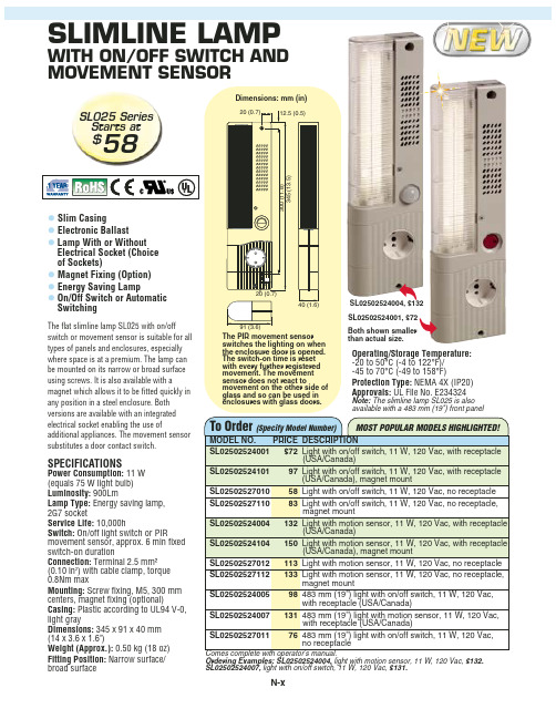
SL02502527011
76 483 mm (19") light with on/off switch, 11 W, 120 Vac, no receptacle
Comes complete with operator’s manual. Ordering Examples: SL02502524004, light with motion sensor, 11 W, 120 Vac, $132. SL02502524007, light with on/off switch, 11 W, 120 Vac, $131.
3UHVVXUH 6WUDLQ DQG )RUFH
Displacement Transducers, Dynamic Measurement Force Sensors, Instrumentation for Pressure and Strain Measurements, Load Cells, Pressure Gauges, Pressure Reference Section, Pressure Switches, Pressure Transducers, Proximity Transducers, Regulators, Pressure Transmitters, Strain Gauges, Torque Transducers, Valves
SLIMLINE LAMP
WITH ON/OFF SWITCH AND MOVEMENT SENSOR
SL025 Series Starts at
$58
Dimensions: mm (in)
20 (0.7)
12.5 (0.5)
300 (11.8) 345 (13.5)
克鲁斯-卜恩空气机场导航灯指南说明书

1200 06095Instruction ManualT axiway, Metric Hardware, Flush to Grade ShallowBase, Color BlackPart Number 21390Copyright © 2013 Cooper Technologies Company For parts and technical service call (860) 683-4300Instruction ManualTaxiway, Metric Hardware, Flush to Grade Shallow Base, Color BlackPart Numbers 213901 RevisionsInstruction ManualTaxiway, Metric Hardware, Flush to Grade Shallow Base, Color BlackPart Numbers 213902 Limited Product WarrantyTHE FOLLOWING WARRANTY IS EXCLUSIVE AND IN LIEU OF ALL OTHERWARRANTIES, WHETHER EXPRESS, IMPLIED OR STATUTORY, INCLUDING, BUTNOT BY WAY OF LIMITATION, ANY WARRANTY OF MERCHANTABILITY ORFITNESS FOR ANY PARTICULAR PURPOSE.Crouse-Hinds Airport Lighting Products ( “the Company”) warrants to each original Buyer ofProducts manufactured by the Company that such Products are, at the time of delivery to theBuyer, free of material and workmanship defects, provided that no warranty is made withrespect to:(a) any Product which has been repaired or altered in such a way, in Company’s judgment, asto affect the Product adversely;(b) any Product which has, in Company’s judgment, been subject to negligence, accident orimproper storage;(c) any Product which has not been operated and maintained in accordance with normalpractice and in conformity with recommendations and published specification of Company;and,(d) any Products, component parts or accessories manufactured by others but supplied byCompany (any claims should be submitted directly to the manufacturer thereof).Crouse-Hinds Airport Lighting Products’ obligation under this warranty is limited to use ofreasonable means to repair or, at its option, replace, during normal business hours, at anyauthorized service facility of Company, any Products which in its judgment proved not to beas warranted within the applicable warranty period. All costs of transportation of Productsclaimed not to be as warranted and of repaired or replacement Products to or from suchservice facility shall be borne by Purchaser. Company may require the return of any Productclaimed not to be as warranted to one of its facilities as designed by Company, transportationprepaid by Purchaser, to establish a claim under this warranty. The cost of labor for installinga repaired or replacement product shall be borne by Purchaser. Replacement parts providedunder the terms of this warranty are warranted for the remainder of the warranty period of theProducts upon which they are installed to the same extent as if such parts were originalcomponents thereof. Warranty services provided under the Agreement do not assureuninterrupted operations of Products; Company does not assume any liability for damagescaused by any delays involving warranty service. The warranty period for the Products is 24months from date of shipment or 12 months from date of first use whichever occurs first.iiiInstruction ManualTaxiway, Metric Hardware, Flush to Grade Shallow Base, Color BlackPart Numbers 21390iv3 Safety NoticesThis equipment is normally used or connected to circuits that may employ voltages that are dangerous and may be fatal if accidentally contacted by operating or maintenance personnel. Extreme caution should be exercised when working with this equipment. While practical safety precautions have been incorporated in this equipment, the following rules must be strictly observed :3.1 KEEP AWAY FROM LIVE CIRCUITSOperating and maintenance personnel must at all times observe all safety regulations. Do not perform maintenance on internal components or re-lamp with power ON.3.2 RESUSCITATIONMaintenance personnel should familiarize themselves with the technique for resuscitation found in widely published manuals of first aid instructions.See Advisory Circular AC 150/5340-26 for additional information.Instruction ManualTaxiway, Metric Hardware, Flush to Grade Shallow Base, Color BlackPart Numbers 213904 Table of ContentsT itle Page (i)1.0 Revisions (ii)2.0 Limited Product Warranty. (iii)3.0 Safety Notices (iv)4.0 Table of Contents (v)5.0 General Description (1)5.1 Shallow Base P/N 21390 (1)6.0 Installation (1)6.1 General (1)6.2 Instructions (2)7.0 Maintenance (3)7.1 Water Removal (3)7.2 Mounting Bolts (3)7.3 Snow Plowing (4)8.0 Volume Calculation (4)FiguresFigure 1 - Installation Fixture 87106-1 (5)Figure 2 - Base / Pavement Detail (6)Instruction ManualTaxiway, Metric Hardware, Flush to Grade Shallow Base, Color BlackPart Numbers 213905 General Description5.1 Shallow Base P/N 21390The 21390 shallow base is designed to mount a Crouse –Hinds eight-inch diameter inset fixture into a taxiway location that will experience roll over loads. It is constructed of black anodized cast aluminum. The 21390-1 version has one molded feed-thru connector with an L-823 receptacle and 457mm (18 inches) long, #10 AWG leads. The 21390-2 version has two molded feed-thru connectors, 180º apart from each other, with L-823 receptacles and 457mm (18 inches) long, #10 AWG leads. The 21390-3 version has one 100mm (3.94 inch) hole in the bottom. The 21390-4 has one 116mm (4.57 inch) hole in the bottom. The 21390-5 does not have any molded feed-thru connectors or holes in the bottom surface. All versions have a M5 ground screw located on the inside bottom surface. An optional external ground wire is offered for all versions. The overall height of the base is 152.5mm (6.00 inches) , with a maximum diameter of 214mm (8.42 inches). The weight of the base is 3.8kg (8.4 pounds). There are two M10 (1.5mm pitch) threaded holes and two M10 hardened stainless steel studs on the mounting surface of the base for securing a fixture. The fixture is supplied with an exterior grade plywood cover held in place by two M10 (1.5mm pitch) x 25mm long A4 (316) stainless steel hex bolts and two M10 2 piece washers, A4 (316) stainless steel. The hex bolts and washers may be re-used to secure the light fixture to the base after initial bonding of base to pavement.6 Installation6.1 GeneralThis manual recommends standard methods and techniques for installing inset light bases in existingpavement. These instructions are general guidelines. They do not provide information for every possible contingency that may occur on the job site. Other methods and variations of those outlined herein may be used.The correct orientation of the light fixtures is extremely important. Careful attention to surveying and light base placement is required. Approval by the appropriate authority, consulting engineer or FAA Airports District Office should be granted for the installation method and materials to be used. Before starting any work;read and understand all instructions, consult the cement/epoxy manufacturer for any special weatherconsiderations, verify that the correct materials, equipment and personnel are in place. For further information, see FAA Advisory Circular 150/5340-30 (latest revision), Design and Installation Details for Airport Visual Aids and FAA Advisory Circular 150/5370-10 (latest revision), Standars for Specifying Construction of Airports, Item P-605 and Item P-606. Use Item P-605 and P-606 materials compatable with the pavement the base will be installed into.Caution:Never handle the assembly by the leads as this can break the waterproof sealInstruction ManualTaxiway, Metric Hardware, Flush to Grade Shallow Base, Color BlackPart Numbers 213906.2 Instructions6.2.1Mark the location of the light fixture and the wireway(s) to it. This is accomplished by using surveymarkers/reference points previously laid out by the survey team.6.2.2Saw cut the wireway. Consult with the appropriate engineer or drawing for the proper wireway width anddepth. These dimensions will vary with the size and number of conductors to be installed in the wireway.Typically, the wires are at least 12.7mm (½-inch) below the pavement surface and existing joint seals. Chamfera 50.8mm (2-inch) radius at all intersections and corners. Where practicable, saw cut through the light locationat base depth. This will allow the pavement material to be easily broken and removed after the hole is drilled. If the wireway(s) have been wet-sawed, flush with a high velocity stream of water immediately after sawing. 6.2.3Drill the light base hole. Consult with the appropriate engineer or drawing for the proper width and depth.These dimensions will vary with the method and materials to be used. Typically, there should be a minimum6.4mm (¼-inch) clearance between the light base side/bottom and the drilled hole when a liquid sealer is to beused.6.2.4Thoroughly clean and dry the hole and wireway(s) to insure a proper bond between pavement and sealer.Sandblast the hole and wireway(s) if necessary.6.2.5Attach the light base to a Part Number 87106-1-installation fixture by removing and retaining the hex bolts andsplit lock washers for future use when installing the light fixture. The plywood cover is to be left on the base during the installation process. Make sure the leveling screws on the installation fixture are in proper working order.6.2.6Set the base/fixture assembly in the prepared hole with the alignment notches and leads-to-wirewayarrangements in the correct orientation.6.2.7Level the fixture with the adjustment screws and a good quality calibrated spirit level (See Figure 1). Set thetop of the light base to flush with grade (See Figure 2) or lowest point of grade if on a sloping surface. Base ona sloping surface is to be level to itself and not with pavement.6.2.8Remove the base/fixture assembly from the hole. Verify that the outside surface of the light base is free of anydirt or foreign material, clean as necessary.6.2.9Splice the wires together in the wireway. Install wedges or clips to hold the conductors in place. Consult withthe appropriate engineer or drawing for the approved methods and materials. Typically, non-woodedwedges/clips are place on three foot centers, with the wires at least ½-inch below the pavement surface andjoint seals6.2.10Terminate the leads per the appropriate drawing. Install temporary dams, if required, to block the wirewayentrance to the drilled hole.6.2.11Prepare the FAA Item P-606 paste and liquid sealing material per manufacturers instructions. Apply FAA ItemP-606 paste to the bottom of cored pavement hole so when base is installed on top of it, the paste will be forced up the exterior sides of base at least 3.2mm (1/8 inch). See Section 8 for calculating the area to be filled.6.2.12Slowly press the base/fixture assembly into the hole. The piston action of the base will spread out the sealerand push it up the walls. Work out any trapped air with a slight rocking motion. Seat the installation fixturefirmly on the pavement, weights (sandbags, blocks, etc.) maybe required to keep the fixture in place. Add FAA Item P-606 liquid material as needed to fill the hole up to within 19mm (.75 inches) from top of the light base.Instruction ManualTaxiway, Metric Hardware, Flush to Grade Shallow Base, Color BlackPart Numbers 213906.2.13Immediately set alignment notches in fixture to survey reference points. This step is critical. The FAAtolerance light base alignment is ±½º from a line parallel with the runway centerline.6.2.14Double-check that the base is level and the top edge of the base (not the plywood) is set flush to grade. Adjustas necessary.6.2.15Allow the sealer to cure per manufacture instructions.6.2.16When the cement/epoxy has cured initially, remove the installation fixture. Fill any voids between base andpavement with FAA Item P-606 paste. Do not fill the 19mm (.75 inch) gap around top of base with P-606paste.6.2.17Fill the 19mm (.75 inch) void around top of base between the base exterior and pavement with FAA Item P-605 flexible sealant. Also fill any wireways in the pavement with the P-605 flexible sealant.6.2.18 Remove plywood cover and mount the light fixture per paragraph7.1. Verify that the light beam(s) andcolor(s) are orientated correctly. Install the mounting bolts per paragraph 7.2.7 Maintenance7.1 Water RemovalThe 21390 light base is designed to exclude both ground and surface water from entering when mated with a Crouse-Hinds fixture. Never handle or carry a base by the lead assembly, this could break the feedthru seal and cause the base to leak. Before installing a light fixture, thoroughly clean the mounting surface and gasket sealing surface on the base. Foreign material on the mounting surface will cause the light fixture to not seat properly and surface water will enter. Apply a thin film of silicone grease ( Dow Corning 1292 or similar )to the fixture gasket. Slowly press the fixture into the base. Install mounting hardware per paragraph 7.2.Establish a regular schedule to inspect and remove water from all light bases. In cold climate locations,freezing water can cause major damage to the light fixture and/or base. If water removal is not practicable, fill the void in the interior between the light fixture and base with pieces of ETHAFOAM brand polyethylene foam.7.2 Mounting BoltsIt is recommended that the mounting bolts ( M10 (1.5mm pitch) x 25mm long) and 2 piece washers ( M10) be type A4 (316) stainless steel (supplied with Crouse-Hinds base). Apply Loctite 243 to the bolts and torque them to 247 +5, -0 in-lbs. (27.9 +.6, -0 N-m). Establish a regular schedule to check the torque of the fixture mounting bolts. Light fixtures in and around the Touchdown Zone area are especially prone to vibration damage if the mounting bolts are not properly torqued. It is recommended that the lock washers be replaced every time a mounting bolt is removed. Check for proper torque at least once a month.Instruction ManualTaxiway, Metric Hardware, Flush to Grade Shallow Base, Color BlackPart Numbers 213907.3 Snow PlowingSnowplow operators should exercise extra care not to strike the light fixtures with snowplow blades. After snowplow removal operations, inspect all light fixtures and bases to locate any damaged units. Basereplacement in winter conditions may not be possible due to low ambient temperatures. Passes over the light rows should be made with a power broom only if practical. Whenever snowplows must traverse in-pavement light fixtures, they should be traveling at less than 8 kph or have the blades lifted clear of the fixtures.Recommended snow removal techniques are described in FAA AC 150/5200-30 (latest revision).8 Volume CalculationTo calculate the amount of sealer material required to set a base in a drilled hole, subtract the volume of the base from the volume of the hole.∙Volume of Part Number 21390 base = 334in3 (5.4 liters)1.(Volume of Drilled Hole) - (Volume of Base) = Volume of Sealer Required.2.(πR²H) – (Volume of Base) = Volume Required, where R = Radius of Drilled Hole, and H = Depth of Drilled Hole. Example:A 21390 base in a 9inch (229mm) diameter, 6.5-inch (165mm) deep hole.3.1415 x4.5in2 x 6.5in= 413in3, 413in3– 334in3 = 79in3 [or 79in3÷1728 = .05ft3 (1.3 liters)Instruction ManualTaxiway, Metric Hardware, Flush to Grade Shallow Base, Color BlackPart Numbers 21390Figure 1Installation Fixture 87106-1Document 2713Rev. EInstruction ManualTaxiway, Metric Hardware, Flush to Grade Shallow Base, Color BlackPart Numbers 21390Figure 2Base/Pavement detail6。
莫加 UC 系列产品说明书

Entry-level Arm-based 64-bit ComputersDual-core, 2-GB RAMCompact Dual-core, 2-GB RAM Built-in LTEValue-added Arm-based 64-bit ComputersQuad-core, 4-GB RAMQuad-core, 4-GB RAM5G/CAN/serial IsolationBuilt-in LTEMoxa Industrial LinuxMoxa's Debian-based industrial-grade stable Linux distribution for long-term projectsFeatures and Benefits5Debian-based distribution that can use all standard Debian packages5Developed as per IEC 62443-4-1 and compliant with IEC 62443-4-2 industrialcybersecurity standards (Moxa Industrial Linux 3 Secure)5Long-term support until 2027 for Moxa Industrial Linux 1 and 2031 for MoxaIndustrial Linux 35Wireless connection management utility with automatic network keep alive andfailover5Ready-to-use APIs and library to ease access to hardware and I/O interfaces5Crash-free robust file system5Over-the air (OTA) software updatesWireless-ready Arm-based 32-bit Computers Built-in cellular or Wi-Fi module, RF type approvals, and carrier approvalsBuilt-in LTE Cat.1Built-in LTECat.1 and Wi-FiBuilt-in LTECat.1 and Wi-FiBuilt-in LTECat.4 with Wi-Fi expansion1. Wireless module is built-in. Refer to the Wireless Connection and Expansion Modules section for details.2. Wireless module must be purchased separately. Refer to the Wireless Connection and Expansion Modules section for details.1 mPCIe for cellular/Wi-Fi1 mPCIe forcellular/Wi-Fi1 mPCIe forcellular/Wi-Fi1 mPCIe forcellular/Wi-Fi1 mPCIe for cellular 1mPCIe for Wi-Fi1 mPCIe forcellular/Wi-FiArm-based 32-bit Computers With Wireless Options Flexibility to add cellular or Wi-Fi capability when needed1. Wireless module must be purchased separately. Refer to the Wireless Connection and Expansion Modules section for details.1 LAN,1 serial2 LAN 2 LAN,2 serial2 LAN,2 serial2 LAN,4 serial2 LAN,4 serial2 LAN,1 serial2 LAN,2 serial3 LAN,8 serialStandard Arm-based 32-bit Computers Low power consumption and small form factorWireless Connectivity and Expansion Modules* Details of cellular and Wi-Fi support with a list of wireless accessory models* Antennas must be purchased separatelyLast updated: Aug. 15, 2023. All specifications are subject to change without notice.。
戴尔 DC912 多功能音响系统用户手册说明书
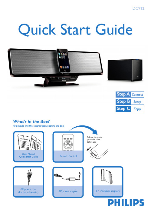
What’s in the Box?YQuick Start GuideDC912Tip– See the User Manual for how toconnect other equipment to thissystem.– Use the supplied AC poweradaptor only! Using any otherpower connection device maydamage your main set!Setting the clock12Connect the AC power adaptor of the system.Connect the AC power cord of the subwoofer to the AC outlet.In case the wireless connection fails due to conflict or stronginterference etc., you may need the following procedures formanual pairing:1In standby mode,press and hold 2; on the set for three seconds toactivate signal transmitting.➜“PAIR” flashes on the display screen.2Press and hold the PAIR button on the rear of the subwoofer forthree seconds to activate signal receiving.➜The LED indicator on the subwoofer flashes in blue and greenalternatively.●If the connection succeeds,the display shows “PASS”.●If the connection fails or the connection cannot be set up successfullywithin 60 seconds,the display shows “FAIL”.1 2 3Insert the USB device’s USB plug into the socket or fully insert the SD/MMC card intothe SD/MMC slot on the top of the system.Press SOURCE once or more (or USB/CARD on the remote control) to selectUSB/CARD.Play the available audio files using playback buttons on the set or remote control (such as 2;, S/T).Playing a USB mass storage device/SD/MMC cardWith the Hi-Fi system, you can use USB flash memory (USB 2.0 or USB1.1),USB flash players(USB 2.0 or USB1.1) and memory cardsTipDetailed playback features and additional functions are described in the accompany owner's manual.C Royal Philips Electronics N.V. 2008All rights reserved.PDCC-ZYL-0835 Power on your iPod player.Select and play your favourite songs stored in the iPod player.45Notes for remote control:–First select the source you wish to control by pressing one of thesource select keys on the remote control (for example iPod,TUNER).–Then select the desired function (for example ÉÅ, à, á).。
T-1000S 操作手册说明书
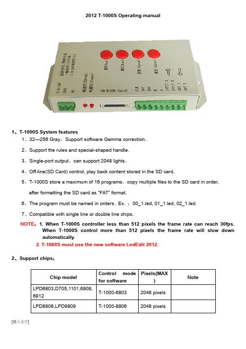
2012 T-1000S Operating manual1、T-1000S System features1、32—256 Gray,Support software Gamma correction。
2、Support the rules and special-shaped handle.3、Single-port output,can support 2048 lights。
4、Off-line(SD Card) control, play back content stored in the SD card.5、T-1000S store a maximum of 16 programs,copy multiple files to the SD card in order,after formatting the SD card as “FAT” format.6、The program must be named in orders . Ex. :00_1.led, 01_1.led, 02_1.led.7、Compatible with single line or double line chips.NOTE:1. When T-1000S controller less than 512 pixels the frame rate can reach 30fps.When T-1000S control more than 512 pixels the frame rate will slow downautomatically.2. T-1000S must use the new software LedEdit 2012.2、Support chips:Chip model Control modefor softwarePixels(MAX)NoteLPD6803,D705,1101,6909,6912T-1000-6803 2048 pixels LPD8806,LPD8809 T-1000-8806 2048 pixelsTM1803,TM1804,TM1809, TM1812 T-1000-TM 2048 pixelsTM1804 andTM1809 aredivided into highand lowTM1903,TM1904,TM1909,TM1912T-1000-TM19 2048 pixels UCS6909,UCS6912,UCS7009,UCS5903T-1000-UCS-32 2048 pixelsUCS1903,UCS1909,UCS1912 T-1000-UCS-2562048 pixels1903 and 1909are divided intohigh and lowUCS3903 T-1000-UCS-10242048 pixelsDMX512 T-1000-DMX 170/512pixelsCompatible withstandardDMX512WS2801,WS2803 T-1000-WS 2048 pixelsWS2811 T-1000-WS2811 2048 pixels WS2811 be divided into high and lowDS189 T-1000-DS189 2048 pixelsTLS3001,TLS3002,TLS3008T-1000-TLS * pixelsP9813 T-1000-P9813 2048 pixelsSM16715 T-1000-SM167152048 pixelsSM16715 bedivided into highand lowSM16716 T-1000-SM167162048 pixelsBS0901,BS0902 T-1000-0901 2048 pixelsBS0815 T-1000-0815 2048 pixels 3、Appearance picture4、Definition of printing : Definition of buttons :DC5V +5V power input GND Power GND input 7.5-24V +7.5-24V power input POWER Power indicator ERROR Error indicator SD CARDSD card slotTTL signal (245/spi signal ): RS485 signal.NOTE :For the TTL(SPI) signal, the controller signal ground must connect to the LED ground directly.5、Mode of connectionButtons 含义SET Save Settings ( to save current settings file and the playback speed )。
H801SE说明书
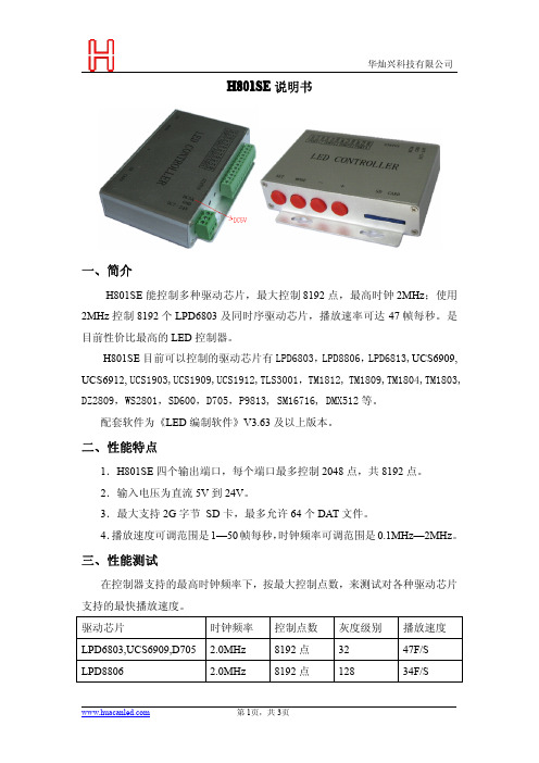
H801SE说明书一、简介H801SE能控制多种驱动芯片,最大控制8192点,最高时钟2MHz;使用2MHz控制8192个LPD6803及同时序驱动芯片,播放速率可达47帧每秒。
是目前性价比最高的LED控制器。
H801SE目前可以控制的驱动芯片有LPD6803,LPD8806,LPD6813,UCS6909, UCS6912,UCS1903,UCS1909,UCS1912,TLS3001,TM1812,TM1809,TM1804,TM1803, DZ2809,WS2801,SD600,D705,P9813,SM16716,DMX512等。
配套软件为《LED编制软件》V3.63及以上版本。
二、性能特点1.H801SE四个输出端口,每个端口最多控制2048点,共8192点。
2.输入电压为直流5V到24V。
3.最大支持2G字节SD卡,最多允许64个DAT文件。
4.播放速度可调范围是1—50帧每秒,时钟频率可调范围是0.1MHz—2MHz。
三、性能测试在控制器支持的最高时钟频率下,按最大控制点数,来测试对各种驱动芯片支持的最快播放速度。
驱动芯片时钟频率控制点数灰度级别播放速度LPD6803,UCS6909,D705 2.0MHz8192点3247F/SLPD8806 2.0MHz8192点12834F/S注:灰度级别是LED驱动芯片的性能,与控制器无关四、参数1.播放速度档(帧每秒):151015202530354045502.时钟频率档(MHz):DMX512时钟固定不变;UCS1903,UCS1909,UCS1912,TM1812只有高速模式,TM1803只有低速模式,TM1809,TM1804高低速可配置,为了达到最佳性能,允许对时钟微调;1.1M 1.0M0.8M0.7M0.6M0.4M0.38M0.33M其他驱动芯片时钟频率调节档2.0M 1.6M 1.3M 1.0M0.8M0.6M0.4M0.2M0.1M五、使用说明1.SD卡在第一次使用,或多次删除后需要格式化成FAT16格式。
LT-600 LED 控制系统规格书
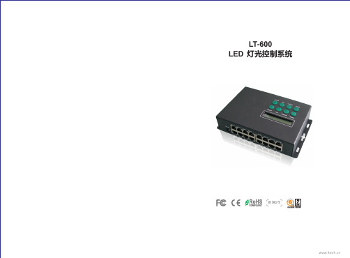
一
技术参数:
LT-600 LED 视频控制系统
工作电压: 输出信号信道: SPI输出: DMX输出: 输入输出端口: 灰度级别: 刷新频率: 联机传输方式: 12Vdc (配100-240Vac电源适配器) 16 路 Max 1364像素 × 16路 21824像素 Max 170像素 × 16路 2720像素 RJ45 最大65536级(64K) 60Hz~3000Hz TCP/IP 标准网络协议 产品尺寸: 包装尺寸: 重量: 脱机储存介质: SD卡容量: 第三方接口: 操作系统: SD记忆卡 2GB Max. DMX512/1990 协议 中、英文Windows 2000/ 2003/XP/Vista/7 L197XW120XH47(mm) L250XW125XH88(mm) 920g(净重) 1450g(毛重)
三
产品配件:
1. 网线 2. 信号线转换器 3. 电源适配器 4. SD 储存卡 5. SD读卡器 2 1 1 1 PCS PCS PCS PCS
16 PCS
网线
信号线转换器
电源适配器
SD 储存卡
SD读卡器
1
2
LT-600 LED lighting control system
LT-600 LED lighting control system
四
产品结构图:
( 2 ) 长按LOCK键锁定/解锁按键:
按键已锁
( 3 ) 按SETUP键进入设置DMX地址: 按MODE+/-增加或减少百位数, 按SPEED+/-增加或减少十位数, 按M1/M2增加或减少个位数。 按LOCK确认
二
功能特点:
1. 一台控制器简单集合了以往多款控制器才能达到的5大功能: ● 以太网实时电脑同步显示控制。 ● 脱机SD卡储存节目点播,节目、速度选择等功能在液晶屏一目了然。 ● 兼容DMX512 协议,连接DMX控制台构建灯光控制网络。 ● 支持WiFi无线传输,适合特殊场合,无需布线。 ● 支持任意时间自动定时播放,实现周一到周日、节假日播放不同节目。 2. 能直接输出DMX信号,也可以控制各种LED驱动芯片,基于如下IC驱动的LED灯具都可以控制: 74HC595, 6B595, MBI5026, DM134, ZQ9712, LPD6803, LPD6813, LPD1101, D705, UCS6909, UCS6912, UCS1903, UCS1909, UCS1912, UCS2903, UCS2909, UCS2912, WS2801, WS2803, WS2811,WS2812, WS2812b, HL1609, SM16716, SD600, P9813, LPD8803, LPD8806, LPD8809, LPD8812, TLS3001, TLS3002, TLS3003, TM1803, TM1804, TM1809, TM1812, MBI6120等等驱动IC。
H802SE说明书
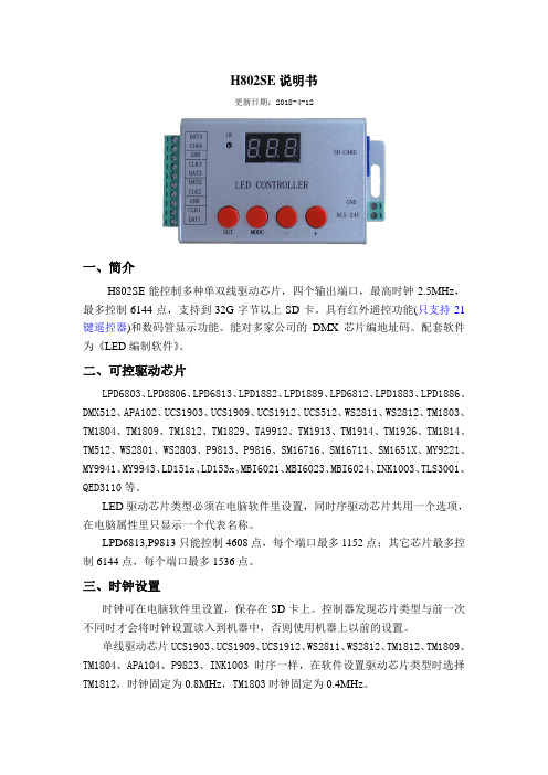
H802SE说明书更新日期:2018-4-12一、简介H802SE能控制多种单双线驱动芯片,四个输出端口,最高时钟2.5MHz,最多控制6144点,支持到32G字节以上SD卡。
具有红外遥控功能(只支持21键遥控器)和数码管显示功能。
能对多家公司的DMX芯片编地址码。
配套软件为《LED编制软件》。
二、可控驱动芯片LPD6803、LPD8806、LPD6813、LPD1882、LPD1889、LPD6812、LPD1883、LPD1886、DMX512、APA102、UCS1903、UCS1909、UCS1912、UCS512、WS2811、WS2812、TM1803、TM1804、TM1809、TM1812、TM1829、TA9912、TM1913、TM1914、TM1926、TM1814、TM512、WS2801、WS2803、P9813、P9816、SM16716、SM16711、SM1651X、MY9221、MY9941、MY9943、LD151x、LD153x、MBI6021、MBI6023、MBI6024、INK1003、TLS3001、QED3110等。
LED驱动芯片类型必须在电脑软件里设置,同时序驱动芯片共用一个选项,在电脑属性里只显示一个代表名称。
LPD6813,P9813只能控制4608点,每个端口最多1152点;其它芯片最多控制6144点,每个端口最多1536点。
三、时钟设置时钟可在电脑软件里设置,保存在SD卡上。
控制器发现芯片类型与前一次不同时才会将时钟设置读入到机器中,否则使用机器上以前的设置。
单线驱动芯片UCS1903、UCS1909、UCS1912、WS2811、WS2812、TM1812、TM1809、TM1804、APA104、P9823、INK1003时序一样,在软件设置驱动芯片类型时选择TM1812,时钟固定为0.8MHz,TM1803时钟固定为0.4MHz。
TLS3001时钟建议不要超过0.8MHz。
RGB数字LED光棍控制器用户手册说明书
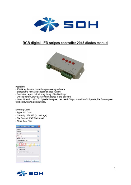
RGB digital LED stripes controller 2048 diodes manualFeatures:- 256 Gray,Gamma correction processing software.- Support the rules and special-shaped handle.- Controller, a port output, may bring 1024/2048 light.- Off-line control, play back content stored in the SD card- Note: When it control 512 pixels the speed can reach 30fps, more than 512 pixels, the frame speed will be slow down automaticallyMemory Card:- Type: SD Card- Capacity: 256 MB (in package)- File Format: FAT file format- Store files: *.ledSpecifications:- Size: 122 mm * 67 mm * 25 mm- Temperature : -40-85 Degrees- Volgate: DC 5 V / DC 7.5-24 V- Power: 3 WTTL signal 245/spi signal and RS485 signal control:Chip type:Buttons:Connection diagram:7.5V-24V DC power input, to provide two sets of power input, select a group can be. 5V Power GroundERROR - Error indicatorPOWER - Power LEDSD CARD - SD card slotCLK - Output CLKDAT -Output DATAGND – Signal GroundA-B - Compatible with DMX signal, differential A, and differential BGND - Signal GroundName of the program(The rule of how to name the programs)The name for NO.2 controller“00_1.led” --------- NO.1 program for No.1 controller“01_1.led” --------- NO.2 program for No.1 controller“02_1.led” --------- NO.3 program for No.1 controller…………………..“15_1.led” --------- NO.16 program for No.1 controllerThe name for NO.2 controller“00_2.led” --------- NO.1 program for No.2 controller“01_2.led” --------- NO.2 program for No.2 controller“02_2.led” --------- NO.3 program for No.2 controller…………….“15_2.led” --------- NO.4 program for No.2 controllerTrouble shootingQuestion 1: After power, the T-1000S ERROR indicator has been flashing without display output Answer: The ERROR indicator has been flashing means the controller did not read the card correctly, possible problems:① SD card is empty, with no effect file.② The effect file in the SD card and the controller model are not match, please choose correct controller model in LedEdit and then re-create the effect file *led.③ SD card did not format to FAT before copy effect files.④ Please check the supply power voltage, the controller can be individually powered to exclude power reasons⑤ Changing the SD card and then test to exclude the possibility of a bad SD cardQuestion 2: The controller is powered on, the indicator is normal, but no effect change in lighting Answer: The reasons for this are as follows:①Check if the lighting′s signal line and the controller connected correctly② If the TTL signal is received, the lamp and the controller must be common ground, that means connect the lighting′s and the controller′s ground together③ Check if the model chose during making display files on the SD card match the chips used in the lifting。
UCS1912中文说明书
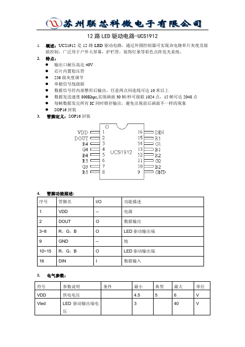
12路LED驱动电路-UCS19121.概述:UCS1912是12路LED驱动电路,通过外围控制器可实现该电路单片灰度及级联控制,广泛用于户外大屏幕,护栏管,装饰灯条等彩色点阵发光系统。
2.特点:z输出口耐压高达40Vz芯片内置稳压管z256级灰度调节z单根信号线级联z数据信号经内部整形后输出,任意两点间连线可达10米以上z数据发送速度800Kbps,实现画面30帧/秒可级联1024点,15帧可达2048点z每帧数据发完所有IC同时锁存输出,避免出现前后画面不一样的现象z SOP16封装3. 管脚定义:SOP16封装4. 管脚功能描述:序号管脚名I/O 功能描述1 VDD -- 电源2 DOUT O 数据输出3~8 R,G,B O LED驱动输出端9 GND -- 地10~15 R,G,B O LED驱动输出端16 DIN I 数据输入5. 电气参数:符号参数说明条件最小典型最大单位VDD 供电电压 4.556 VVled LED驱动输出端电压 3 40V6. 电路功能描述:电路采用单线通讯方式级联,数据用归零码发送。
电路上电后,从DIN 脚输入数据,一个电路有12路LED 输出端,即4组RGB 。
每路输出需要8位二进制数设置灰度,一组RGB 需要24位二进制数,数据高位先输入,结构如下:R G B 0000_0000 ~ 1111_11110000_0000 ~ 1111_11110000_0000 ~ 1111_11118位二进制数从0000_0000到1111_1111对应每路的256级灰度,最小灰度(0000_0000)是0,即LED 不亮,1111_1111对应最大亮度。
一个电路需要共96位数据来设置各个RGB 的灰度,数据输入顺序R1G1B1,R2G2B2,R3G3B3,R4G4B4。
当输入的数据满96位后,电路开始转发数据,即将输入的数据经内部译码,编码处理后从DOUT 端输出进入下一级电路,从而实现多电路级联工作。
马尔杜·电子(Marshall Electronics)CV610-U2操作手册说明书

CV610-U2 Operation Manual Accessories Table of ContentsSAFETY GUIDELINES (3)ACCESSORIES (3)QUICK START (4)PRODUCT HIGHLIGHTS (5)RESOLUTION & FRAME RATE SETTINGS (5)CAMERA SPECS (5)CAMERA INTERFACE (6)CAMERA DIMENSIONS (6)IR REMOTE CONTROLLER (7)OSD MENU (8)VISCA IN (RS232) PORT (10)VISCA PROTOCOL (10)IR TRANSFER (IR PASS) (17)UVC CONTROL (17)WALL MOUNT INSTALLATION (18)1. Camera2. Power Adapter3. CV610-U2-WM - Wall Mount4. Power Cable5. RS232 Control Cable6. USB2.0 Cable7. Remote Controller (battery not included)8. User Manual9. Double-sided Adhesive IMPORTANT SAFETY INSTRUCTIONS:• Remove lens cover before plugging camera into power source.• Before starting operation, please fully read and follow all instructions in the manual. For your safety, always keep this manual with the camera for reference.• The camera power input range is 100-240VAC (50-60Hz), ensure the power supply input within this range before powering on.• The camera power voltage is 12VDC, rated currency is 1.5A. We suggest you use it with the original power supply adapter supplied in the box.• Please keep the power cable, video cable and control cable in a safe place. Protect all cables especially the connectors from moisture and dirt.• Operational environment: 32ºF to 122ºF ( 0ºC to 50ºC) and humidity less than 90%. To avoid any danger, do not put anything inside the camera, and keep away from corrosive liquids.• Avoid stress, vibration and jolts during transportation, storage and installation.• Do not detach the camera housing and cover. For any service, please contact authorized technicians.• RF cable and control cable should be individually shielded, and cannot be substituted with other cables. Do not direct the camera lens towards strong light, such as the sun or the intensive light.• Always use a dry, soft cloth to clean the camera housing. Only use neutral cleaning agents when there is need to clean smudges or dirt from camera body. To avoid damage on the camera lens, only use a soft microfiber cloth.• Do not carry or move the camera by holding the camera head. To avoid mechanical damage of internal gears, do not rotate the camera head by hand.• Put the camera on a fixed desk or platform, avoid installing on surfaces that are not level.•Power Supply Polarity (Drawing) below:CV610-U2 SPECIFICATIONS 1. REMOVE Lens Cover and check all cable connections to be sure they are all firmlyconnected before powering on2. Dial Switch Setting (at the bottom of the camera):• Compact, ergonomically designed housing perfect for small huddle rooms or locations • Supports advanced Ambarella DSP , 1/2.8 inch 5MP image sensor, and high quality 10X 62.5 degree FOV optical lens, provides crystal clear image quality • Fast switching between different video formats: less than 1 second • 10X Optical Zoom + 12X Digital Zoom • Fast and accurate focus performance • Easy firmware upgrade - (field-upgradable)• USB2.0 high speed output • Effective RS232/485 serial control. Up to 128 presets • Compatible with the majority of videoconferencing software (UVC1.5 protocol standard)• Camera comes with accurate IR Remote Control unit •IR transfer/IR pass function: excepts signals from other codec’s and IR remote control signals CV610-U2 Operation Manual CV610-U2 SpecificationsThe Marshall CV610-U2 acts as a UVC command slave to Teleconference, U.C. or Video Capture Software programs that use it as a USB capture device. Once selected as an available camera, these software platforms send commands to camera as to compatible resolutions and frame rates based on bandwidth, software parameters, and/or computer capabilities. Some software platforms allow for direct adjust commands to change resolution and frame-rates, such as VLC Player and others. CV610-U2 adjusts as commanded by software platform or to nearest resolution settings available (1080p, 720p, 480p). There is no way to manually adjust resolutions and frame-rates from camera or cameraOSD menu, since it relies on UVC (USB video class) commands. CV610-U2 adheres to UVC1.5 protocol standards. Note: Normal Working Mode: SW-1~5: ON, SW-6: OFFLEARNING FUNCTIONCAMERA DIMENSIONS (mm)1. Camera Lens2. Camera Base3. IR Receiver Panel4. Indicator Light5. Dial Switch6. Tripod Screw Hole7. Installation Hole8. RS232 (VISCA IN) Port9. USB2.0 Port10. DC12V Power Input11. Power Indicator light (red)LED Function Instruction LED Light on REMOTE (top right of controller) - explained:When LED light turns RED while pushing button - means remote is controlling CAMERA When LED light turns GREEN while pushing button - means remote controlling CODEC When LED light turns BLUE while pushing button - means remote controlling TV;This can be changed by pushing RED(Camera), GREEN(Codec), or BLUE(TV).POWER Buttons (on top of controller):RED button with picture of camera: During normal work, one short press of this button will send camera into standby mode; short press again will start self-startup configuration and go to HOME position or PRESET no. 0 if that has been assigned.GREEN button with picture of people: Codec power button (read more about button coding)BLUE button with picture of television: TV power button (read more about button coding)1.Press the green button, LED indicator light will illuminate green for 1 second, this means that camera is switching to video terminal/codec control mode;2.Single Button Coding: long press (3seconds) Home + number”1” button simultaneously, the green indicator LED will light, this enters button learning mode, press the buttons which need to be learned, LED will start flickering(1HZ), now camera can start learning keys: get the codec remote point to the camera remote’s infrared tube ( about 10cm distance), then press the button which needs to be learned, the LED flickers when learning finishes; press other buttons which also need to be learned; Press the Home+”0” buttons simultaneously to exit and save all remote data. If the button learning fails, the camera will enter normal working mode after 15seconds, LED will extinguish. 3. All Button Coding: long press (3seconds) Home+number”2” button simultaneously, the green indicator LED will start flickering(1HZ), to enter all button learning mode: get codec remote point to the camera remote’s infrared tube( about 10cm distance), to start all button coding mode, the LED will extinguish when learning finished.If the button learning fails, the camera will enter normal working mode after 15seconds, LED will extinguish. Focus (Left): +/- Manual focus, operational when manual focus mode is selected;Zoom (Right): +/-Controls the lens zoom rate;Navigate: Up/Down/Left/Right In normal working mode, use navigate keys to control pan/tilt;Confirm/Home button:In normal working mode, short press to let the camera go back to Home position.Number buttons Set Preset: Long press(3seconds) the number button to save preset;Clear Preset: Clear+number button to clear the relative preset; Long press (3seconds) the Clear button to clear all preset;Run Preset: Short press the number button to run the relative preset.Menu button:show the camera version1. Once camera is powered up and working, press the Menu button on the IR remote control to enter the OSD menu (seepic.1); once changes are made press the OSD menu buttonagain to exit and save modified parameters.2. Use the navigate buttons (up/down/left/right) to choose whichfunction to select. As picture 1 shows, once selection is made,the selected option will change to gray background highlight.Press the right navigate button to go to the sub menu (see pic.2).3. In the sub menu, once again press the up/down navigate buttons to scroll and select, use left/rightnavigate button to cycle through selection options parameters.4. Select the last option “RETURN” and press the left navigate button to get back to main menu orprevious menu.5. Press OSD button again to exit the menu.6. The following pages outline the Menu structure as it appears in OSD Menu:24. All Button Sending Mode: long press (3seconds) the Menu+ number “3” button simultaneously, the remote willenter all button sending mode.5. Similar operation for the TV control mode learning.Part 1 - Camera Return CommandPart 2 - Camera Control CommandPart 3 - Inquiry CommandCAM_WBModeIng8x 09 04 35 FF y0 50 00 FF Autoy0 50 01 FF Indoor modey0 50 02 FF Outdoor mode y0 50 03 FF OnePush mode y0 50 04 FF ATWy0 50 05 FF ManualCAM_RGainIng8x 09 04 43 FF y0 50 00 00 0p 0q FF pq: R Gain CAM_BGainIng8x 09 04 44 FF y0 50 00 00 0p 0q FF pq: B GainCAM_AEModeIng8x 09 04 39 FF y0 50 00 FF Full Autoy0 50 03 FF Manualy0 50 0A FF Shutter priority y0 50 0B FF Iris priorityy0 50 0D FF BrightCAM_ShutterPosIng8x 09 04 4A FF y0 50 00 00 0p 0q FF pq: Shutter Position CAM_IrisPosIng8x 09 04 4B FF y0 50 00 00 0p 0q FF pq: Iris Position CAM_GainPosiIng8x 09 04 4C FF y0 50 00 00 0p 0q FF pq: Gain Position CAM_ BrightPosiIng8x 09 04 4D FF y0 50 00 00 0p 0q FF pq: Bright PositionCAM_ExpCompModeIng8x 09 04 3E FF y0 50 02 FF On y0 50 03 FF OffCAM_ExpCompPosIng8x 09 04 4E FF y0 50 00 00 0p 0q FF pq: ExpComp Position CAM_ApertureIng8x 09 04 42 FF y0 50 00 00 0p 0q FF pq: Aperture GainCAM_MemoryIng8x 09 04 3F FF y0 50pp FF pp: Memory number lastoperated.SYS_MenuModeIng8x 09 06 06 FF y0 50 02 FF On y0 50 03 FF OffCAM_LR_ReverseIng8x 09 04 61 FF y0 50 02 FF On y0 50 03 FF OffCAM_PictureFlipIng8x 09 04 66 FF y0 50 02 FF On y0 50 03 FF OffCAM_IDIng8x 09 04 22 FF y0 50 0p 0q 0r 0s FF pqrs: Camera ID CAM_VersionIng8x 09 00 02 FF y0 50 ab cdmn pq rs tu vw FFIR_Transfer8x 09 06 1A FF y0 50 02 FF On y0 50 03 FF OffPan-tiltMaxSpeedIng8x 09 06 11 FF y0 50 ww zz FF ww: PanMaxSpeedzz: Tilt Max SpeedPan-tiltPosIng8x 09 06 12 FF y0 50 0w 0w 0w 0w0z 0z 0z 0z FF wwww: PanPosition zzzz: Tilt PositionNote: (x) means the camera address; (y)=(x + 8).VISCA PAN / TILT ABSOLUTE POSITION VALUEVISCA PAN / TILT ABSOLUTE POSITION VALUE1. Currently the camera support NEC code format. For customization with other codes, please contact us.2. Once the camera finish power configuration, enable the IR transfer function via sending COM command.3. Get the targeted remote controller point to the camera IR receiver, press keys on the remote controller, then the camera will output the received IR code via VISCA IN port.4. IR Transfer output format: XX XX XX XX FF5. The camera can save all setting, no need to re-set after power circle.XX XX XX XX: Remote Controller Code FF: End Code CV610-U2 Operation Manual IR Transfer (IR PASS)Marshall ElectronicsTel: (800) 800-6608 / (310) 333-0606 • Fax: 310-333-0688。
光学传感器 OUSAF12 操作手册说明书
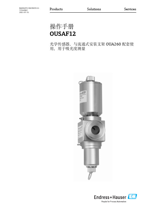
Products Solutions Services操作手册OUSAF12光学传感器,与流通式安装支架OUA260配套使用,用于吸光度测量BA00497C/28/ZH/03.21715428432021-07-31文档信息OUSAF122Endress+Hauser1文档信息1.1警告1.2信息图标附加信息,提示允许或推荐的操作禁止或不推荐的操作参见设备文档参考页面参考图操作结果1.3 设备上的图标参见设备文档资料此类产品不可作为未分类城市垃圾废弃处置。
必须遵循规定条件将产品寄回制造商废弃处置。
OUSAF12基本安全指南Endress+Hauser32基本安全指南2.1人员要求•仅允许经培训的专业技术人员进行测量系统的安装、调试、操作和维护。
•执行特定操作的技术人员必须经工厂厂方授权。
•仅允许电工进行设备的电气连接。
•技术人员必须阅读《操作手册》,理解并遵守其中的各项规定。
•仅允许经专业培训的授权人员进行测量点故障排除。
仅允许制造商或其服务机构直接进行《操作手册》中未描述的维修操作。
2.2 指定用途传感器用于液体介质的可见光/近红外光吸光度测量。
传感器满足各类应用要求在工业领域内应用广泛,例如:•悬浮固体浓度测量•制药和生物技术•化工行业•造纸与纸浆行业•中间相检测•食品与饮料行业•化工行业•油气行业•离心机和分离器控制除本文档指定用途外,其他任何用途均有可能对人员和整个测量系统的安全造成威胁,禁止使用。
由于不恰当使用,或用于非指定用途而导致的设备损坏,制造商不承担任何责任。
2.3 工作场所安全用户有责任且必须遵守下列安全标准的要求:•安装指南•地方标准和法规•防爆保护法规电磁兼容性•产品通过电磁兼容性(EMC)测试,符合国际工业应用的适用标准要求。
•仅完全按照本《操作手册》说明进行接线的产品才符合电磁兼容性(EMC)要求。
2.4操作安全在进行整个测量点调试之前:1.检查并确认所有连接均正确。
奥斯汀休斯UM-PPS-01-Q212V9智能远程电源管理说明书

Intelligent Remote Power ManagementUser Manual PPS-01, IP dongle GUI softwareMTS switched PDUMT monitored PDUDesigned and manufactured by Austin HughesLegal InformationFirst English printing, October 2002Information in this document has been carefully checked for accuracy; however, no guarantee is given to the correctness of the contents. The information in this document is subject to change without notice. We are not liable for any injury or loss that results from the use of this equipment.Safety InstructionsPlease read all of these instructions carefully before you use the device. Save this manual for future reference.■ Unplug equipment before cleaning. Don’t use liquid or spray detergent; use a moist cloth.■ Keep equipment away from excessive humidity and heat. Preferably, keep it in an air-conditioned environment with temperatures not exceeding 40º Celsius (104º Fahrenheit).■ When installing, place the equipment on a sturdy, level surface to prevent it from accidentally falling and causing dam age to other equipment or injury to persons nearby.■ When the equipment is in an open position, do not cover, block or in any way obstruct the gap between it and thepower supply. Proper air convection is necessary to keep it from overheating.■ Arrange the equipment’s power cord in such a way that others won’t trip or fall over it.■ If you are using a power cord that didn’t ship with the equipment, ensure that it is rated for the voltage and current labeled on the equipment’s electrical ratings label. The voltage rating on the cord should be higher than the one listed on the equipment’s ratings label.■ Observe all precautions and warnings attached to the equipment.■ If you don’t intend on using the equipment for a long time, disconnect it from the power outlet to prevent being dam aged by transient over-voltage.■ Keep all liquids away from the equipment to minimize the risk of accidental spillage. Liquid spilled on to the power supply or on other hardware may cause damage, fi re or electrical shock.■ Only qualifi ed service personnel should open the chassis. Opening it yourself could damage the equipment and invali date its warranty.■ If any part of the equipment becomes damaged or stops functioning, have it checked by qualifi ed service personnel.What the warranty does not cover■ Any product, on which the serial number has been defaced, modifi ed or removed.■ Damage, deterioration or malfunction resulting from:□ Accident, misuse, neglect, fi re, water, lightning, or other acts of nature, unauthorized product modifi cation, orfailure to follow instructions supplied with the product.□ Repair or attempted repair by anyone not authorized by us.□ Any damage of the product due to shipment.□ Removal or installation of the product.□ Causes external to the product, such as electric power fl uctuation or failure.□ Use of supplies or parts not meeting our specifi cations.□ Normal wear and tear.□ Any other causes which does not relate to a product defect.■ Removal, installation, and set-up service charges.Regulatory Notices Federal Communications Commission (FCC)This equipment has been tested and found to comply with the limits for a Class B digital device, pursuant to Part 15 of the FCC rules. These limits are designed to provide reasonable protection against harmful interference in a residential instal-lation.Any changes or modifi cations made to this equipment may void the user’s authority to operate this equipment. This equipment generates, uses, and can radiate radio frequency energy and, if not installed and used in accordance with the instructions, may cause harmful interference to radio communications.However, there is no guarantee that interference will not occur in a particular installation. If this equipment does cause harmful interference to radio or television reception, which can be determined by turning the equipment off and on, the user is encouraged to try to correct the interference by one or more of the following measures:■ Re-position or relocate the receiving antenna.■ Increase the separation between the equipment and receiver.■ Connect the equipment into an outlet on a circuit different from that to which the receiver is connected.The company reserves the right to modify product specifi cations without prior notice and assumes no responsibility for any error which may appear in this publication.All brand names, logo and registered trademarks are properties of their respective owners.Copyright 2011 Austin Hughes Electronics Ltd. All rights reserved.The equipment comes with the standard parts shown on the package contents. Check and make sure they are included and in good condition. If anything is missing, or damage, contact the supplier immediately.UnpackingPackage contents( 1 ) Vertical MTS / MT PDU x 1- VMS mounting screw, set of 2 or 3 - VMB mounting bracket set2 -3 sets+M4M4 x 2M6 x 2M6 nut x 2 PEGM6 nutBracket x 2( 2 ) Rackmount MTS / MT PDU x 1ORPower ON■ Connect the PDU into an appropriately rated receptacle■ When the PDU is power on, the LED display will light up. That means all outlets are activated■ Keep the equipments in the power off position until it is plugged into the PDUDon’t exceed the outlet, branch or phase limitations< 1.1 > PDU meter setting & cascade< 1.2 > IP dongle installation & connection < 1.3 > IP dongle confi guration< 1.4 > PPS-01 IP dongle GUI Software P. 1 - 2 P. 3 - 4 P. 5 P. 6 - 7ContentUsing the dip switch no. 1, 2, 3, 4 & 8 to setup each PDU level as below :Cascaded PDUs Dip switch no.123481st PDUOn On On On Off 2nd PDU Off On On On Off 3rd PDU On Off On On Off 4th PDU Off Off On On Off 5th PDU On On Off On Off 6th PDU Off On Off On Off 7th PDU On Off Off On Off 8th PDU Off Off Off On Off 9th PDU On On On Off Off 10th PDU Off On On Off Off 11th PDU On Off On Off Off 12th PDU Off Off On Off Off 13th PDU On On Off Off Off 14th PDU Off On Off Off Off 15th PDU On Off Off Off Off 16th PDUOff Off Off OffOffCascaded PDUs setting< 1.1 > PDU meter setting & cascadePDU cascade portDIP Switch <ON>1Current display 2Dip switch3Reset button4■ For rackmount PDU, on the front panel left , on the rear panel2341DIP Switch <OFF>1st level PDU Dip switch setting Dip switch settingDip switch settingTo LINK port of next PDU ( Up to 16 levels )Meter display settingCurrent display Dip switch no.57Circuit A + Circuit B Off Off Circuit A only On Off Circuit B onlyOnOnCAT. 5 / 6cableCAT. 5 / 6cableIP dongle ( refer to P.3 - 9 )Dip switch 6Enable Off DisableOnAudio alarmUp to 20 metersUp to 20 meters■ The PDU can be cascaded up to 16 levels■ For IP PDU access simply connect 1 x IP dongle - IPD-01■ 1 x IP dongle allows access to 16 levelsUsing the dip switch no. 5 & 7 to setup each PDU meter display as below :Using the dip switch no. 6 to setup each PDU audio alarm as below :3rd level PDU2nd level PDU< 1.2 > IP dongle installation & connectionTo remote PDU over IP, users can order IP dongle :I PD-01 IP dongle for vertical PDUVertical IP dongle installation steps :- slide the IP dongle on the plate above the meter- plug the RJ-45 connector of IP dongle into the LINK port of the 1st level PDU meter - use the CAT. 5 / 6 cable to connect IP dongle to network deviceI PD-H01 IP dongle for rackmount PDUHorizontal IP dongle installation steps :- fi x the IP dongle on the rear side of rackmount PDU with 4 screws- plug the RJ-45 connector of IP dongle into the LINK port of the 1st level PDU meter - use the CAT. 5 / 6 cable to connect IP dongle to network deviceCustomer’s network device( router or hub )< 1.3 > IP dongle con fi gurationAfter the completion of IP dongle connection, please take the following steps to con figure the IP dongle :IP dongle on 1st level PDU4. Click Scan to search the connected IP dongles5. Enter the device name ( min. 4 char. / max. 16 char. ) in the device name fi eld. The default is Name.6. Enter the location in the location fi eld ( min. 4 char. / max. 16 char. ). The default is Rack_001.7. Enter the password for security in the password fi eld ( min. 8 char. / max. 16 char. ). The default is 00000000.8. Re-enter the new password in the Con fi rm new password fi eld.9. Change the desired IP address / Subnet mask / Gateway, then click Save to con fi rm the setting to IP dongle.10. The default IP address is as below: IP address : 192.168.0.1 Subnet mask : 255.255.255.0 Gateway :192.168.0.254Reconnect the IP dongle with the network device ( router or hub ), after fi nish IP dongle con fi guration.Ensure the PDU inpower ON status1. Prepare a notebook computer to download the IP setup utilities from the link : /support/utilities/infrapower/IPdongleSetup.msi2. Double click the IPDongleSetup.msi and follow the instruction to complete the installation.3. Go to each fi rst level PDU with the notebook computer & a piece of CAT. 5 / 6 cable to con fi gure the IP dongle by IP setup utilities as below. Please take the procedure for all IP dongles ONE BY ONE .< 1.4 > PPS-01 IP dongle GUI SoftwareEach IP dongle provides a built-in GUI software, PPS-01, which allows user, via an I.E. web browser, to see PDU’s data and remotely manage the PDU over a TCP/IP Ethernet network.Each I.E. supports ONLY one IP dongle. If the user installs more IP dongles, multi windows will be required.< Status >- Data refresh every 10 seconds - Disable Refresh during data inputStatus of all connected PDUs Aggregate current on each PDULatest loading on each circuit of PDU Alarm threshold setup: save the changes: quit without changesPPS-01 is a management software but with very limited features. The user can use advanced software, InfraPower Manager IPM-01.Step 1. Open Internet Explorer ( I.E. ), version 6.0 or above Step 2. Enter the con fi gured IP dongle address into the I.E. address bar ( Refer to set up IP utilities p.5 )Step 3. Enter password ( Refer to set up IP utilities P.5 )< Setup >IP dongle con fi guration settingPassword settingNetwork setting Hardware information provided: save the changes : restart the PDU meter ( outlets are still activated ): reload the PDU information < Details >- Data refresh every 10 seconds - Disable Refresh during data input On / Off status of each outletRemote on / off outlet ( MTS switched PDU only )Rename outlet device, PDU and location Aggregate current on the PDU : reload the IP dongle to factory default( Press Default > Apply ): restart the IP dongle: save the changesThe company reserves the right to modify product specifi cations without prior notice and assumes no responsibility for any error which may appear in this publication.All brand names, logo and registered trademarks are properties of their respective owners.Copyright 2012 Austin Hughes Electronics Ltd. All rights reserved.。
19102客户服务指南说明书
Change the setting by turning switch on the back of the horn strobe (Figure 1). Switch settings are shown in raised lettering on the back of the horn strobe.
until tabs (a) on horn strobe assembly
click into slots on mounting plate.
a 2
Figure 6, Attach Horn Strobe Assembly
© Allegion 2013 Printed in U.S.A. 19102 Rev. 12/13-f
Red: Must apply voltage for horn strobe to operate. Remove and reapply voltage to reset latched horn strobe.
Violet: Apply voltage to prevent horn strobe from activation.
*19102*
19102
1910S-1 / L1910S-1 Horn Strobe and
Latching Horn Strobe
Installation Instructions
SPECIFICATIONS
Voltage:
12 or 24 VDC
Current:
28 mA maximum average
sick uc12超声波传感器说明书
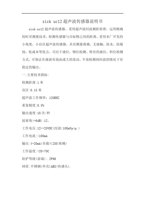
sick uc12超声波传感器说明书
sick uc12超声波传感器,采用超声波回波测距原理,运用精确的时差测量技术,检测传感器与目标物之间的距离,采用本厂开发的小角度,小盲区超声波传感器,具有测量准确,无接触,防水,防腐蚀,低成本等优点,可应于液位,物位检测,特有的液位,料位检测方式,可保证在液面有泡沫或大的晃动,不易检测到回波的情况下有稳定的输出。
一:主要技术指标:
检测距离:1米
盲区:0.15米
超声波工作频率:120KHZ
重复精度:0.5%
输出速度:10次/秒
波束角(-6dB):12。
工作电压:12--25VDC(纹波<100mVp-p.)
工作电流:<100mA
输出:4-20mA(负载≤250欧姆)
工作温度:-20-70C
防护等级(前端):.IP66
材质:不锈钢(外壳)ABS(传感头).。
- 1、下载文档前请自行甄别文档内容的完整性,平台不提供额外的编辑、内容补充、找答案等附加服务。
- 2、"仅部分预览"的文档,不可在线预览部分如存在完整性等问题,可反馈申请退款(可完整预览的文档不适用该条件!)。
- 3、如文档侵犯您的权益,请联系客服反馈,我们会尽快为您处理(人工客服工作时间:9:00-18:30)。
12路LED驱动电路-UCS1912
1.概述:UCS1912是12路LED驱动电路,通过外围控制器可实现该电路单片灰度及级
联控制,广泛用于户外大屏幕,护栏管,装饰灯条等彩色点阵发光系统。
2.特点:
●输出口耐压高达40V
●芯片内置稳压管
●256级灰度调节
●单根信号线级联
●数据信号经内部整形后输出,任意两点间连线可达10米以上
●数据发送速度800Kbps,实现画面30帧/秒可级联1024点,15帧可达2048点
●每帧数据发完所有IC同时锁存输出,避免出现前后画面不一样的现象
●SOP16封装
3. 管脚定义:SOP16封装
5. 电气参数:
6. 电路功能描述:
电路采用单线通讯方式级联,数据用归零码发送。
电路上电后,从DIN 脚输入数据,一个电路有12路LED 输出端,即4组RGB。
每路输出需要8
位二进制数设置灰度,一组
8位二进制数从0000_0000到1111_1111对应每路的256级灰度,最小灰度(0000_0000)是0,即LED 不亮,1111_1111对应最大亮度。
一个电路需要共96位数据来设置各个RGB 的灰度,数据输入顺序R1G1B1,R2G2B2,R3G3B3,R4G4B4。
当输入的数据满96位后,电路开始转发数据,即将输入的数据经内部译码,编码处理后从DOUT 端输出进入下一级电路,从而实现多电路级联工作。
当所有的电路都接受到新的数据后,输入一个reset 信号,新的数据生效。
RGB 端口根据输入的数据输出相应的占空比信号,该信号刷新周期约1.5mS 。
数据码型说明:
电路可以单个使用,也可以级联使用。
0码
1码 Reset 码
级联示意图:,
为保证第一帧输入的数据有效,在输入第一帧数据前先输入一个reset 信号,每一帧数据最先输入的96位进入IC1,之后是IC2,依次向后直到最后一个IC ,所有的IC 都输入了数据后再输入reset 信号,之后数据才生效,表示一帧数据完成。
可以输入下一帧数据了。
N 代表系统中IC 个数。
注:为降低干扰和保护IC 输入输出端,必须在电路DIN 和DOUT 端各串接一个39~50欧姆电阻。
7. 电源配置:电路可以用5~40V 供电,VDD 脚对地电容0.1uF~10uF ,应尽量靠近IC 。
电源上串联的电阻根据VCC 电压不同需要选择不同阻值。
不能将VDD 直接接高于5V 的电源。
串联电阻阻值的计算以芯片工作电流(Idd )等于2.5mA 为准。
其计算公式如下: R1=(VCC-5)/Idd
例如:VCC=6V ,则R1=(6-5)/0.0025=0.4K
VCC=18V ,则R1=(18-5)/0.0025=5.2K 8. 应用图:
reset
N 个96位数据 reset N 个96位数据 reset N 个96位数据 reset
9. 封装外形尺寸图:SOP16(单位:mm)。
