2440_WinCE操作GPIO
DVK2440I-LCD700I-T开发指南-WinCE 篇
DVK2440开发指南WINCE5.WINCE5.00篇本手册适用于DVK2440等采用DM9000百兆网卡的零点电子S3C2440开发板系列产品的WINCE5.0开发,详细产品信息请参见公司网站/目录一、安装WINCE5.0开发环境 (1)二、安装基于DVK2440的BSP包 (8)三、新建工程并生成新的WindowsCE映象文件 (11)四、下载并烧写Wince操作系统 (25)五、把nk.nb0下载到SDRAM直接运行WINCE (39)六、建立Wince平台和PC的连接 (42)七、使用Platform builder导出自己的SDK (44)八、如何使用Platform builder的远程编辑工具 (54)九、在EmbededVC++4.0建立应用程序 (57)十、在VS2005建立应用程序,并下载到开发板上运行 (63)十一、如何修改WINCE网卡MAC地址 (72)十二、结束语 (73)装WINCE5.0开发环境一、安装一、安以下步骤基于Windows XP操作,windows2000及以前操作系统不支持WINCE5.0开发环境的安装。
如果PC机原来没有安装过dotnet framework1.1,请先安装dotnetfx.exeStep1:打开WINCE5.0安装包文件夹,找到其中的安装文件,并双击开始安装点击Install开始安装Step2:进入"Welcome"界面,点"Next"继续Step3:进入"License Agreement"界面,点"Next"继续Step4:进入序列号输入界面,输入正确的序列号,点"Next"继续Step5:选择安装类型,按缺省安装即Custom,点"Next"继续Step6:选择安装目录,点"Next"继续Step7:在定制安装中选择您所需要的系统平台,(对基于S3C2440的用户来说,请一定要安装ARMV4I两个选项).点"Next"继续Step8:开始安装安装过程比较漫长,可以去喝杯茶,过20多分钟再回来。
2440硬件使用说明

一、中心简介...................................................................................................................................4 二、开发板硬件资源:...................................................................................................................5 1、核心板参数.........................................................................................................................5 2.1.1 尺寸:....................................................................................................................5 2.1.2 中央处理器:........................................................................................................ 5 2.1.3 SDRAM:.................................................................................................................5 2.1.4 FLASH Me
阳初 2440 开发 板说明书

阳初2440开发板使用说明书2008‐3‐20目录第一章 开发板的介绍 (6)1.1开发板简介 (6)1.1.1硬件资源特性 (6)1.1.2用户光盘资源说明 (7)1.2 Linux特性 (7)1.3开发套件配件清单 (8)第二章 开发板使用说明 (8)2.1 开发板设置及连接 (9)2.1.1 开发板外部接口连接 (9)2.1.2 设置超级终端(主机PC) (9)2.2 开发板BIOS功能及使用说明 (12)2.2.1 开机进入BIOS模式 (13)2.2.2 安装USB驱动 (14)2.2.3 vivi子菜单功能说明 (14)2.3 预装linux系统的功能简介 (14)2.3.1 设置开发板网络 (15)2.3.2 如何中止程序的运行 (15)2.3.3 挂载USB闪存盘(U盘) (16)2.3.4 使用SD卡 (17)2.3.5 如何通过串口与PC互相传送文件 (17)2.3.6 串口2 的测试 (19)2.3.7 使用ftp传递文件 (21)2.3.8 设置并保存系统实时时钟 (26)2.3.9 如何掉电保存数据到Flash (26)2.3.10 使用telnet登陆开发板 (26)2.3.11 如何设置开机自动运行程序 (27)第三章 安装嵌入式系统 (28)3.1安装启动程序 (28)3.1.1在PC上安装JTAG下载线的驱动程序 (29)3.1.2烧写Bootloader (35)3.2串口安装Linux (36)3.2.1分区并格式化闪存 (36)3.2.2下载Bootloader (37)3.2.3下载Linux的内核映象 (39)3.2.4下载文件系统映象 (40)3.2.5启动Linux系统 (41)3.3 tftp安装linux (41)3.3.1 启动TFTP服务器 (41)3.3.2 网络设置 (43)3.3.3 下载内核映象以及文件系统 (45)3.4安装WinCE系统 (47)3.4.1下载WindowsCE启动程序 (47)3.4.2下载WindowsCE映象 (49)3.4.3启动WindowsCE (54)第四章 ADS1.2 集成开发环境的使用 (54)4.1 使用ADS创建LED工程 (54)4.1.1 建立一个工程 (54)4.1.2 编译和链接工程 (58)4.2 下载和运行 (65)第五章 建立linux开发环境 (66)5.1 linux发行版本介绍 (66)5.2 完全图解安装Redhat9.0 (70)5.2.1用grub引导双操作系统 (70)5.2.2使用vmware虚拟机 (74)5.3 配置minicom终端通讯工具 (75)5.4 配置网络文件系统NFS服务 (77)5.5 通过NFS启动系统 (78)5.6 配置PC机Linux的ftp服务 (78)5.7 配置PC机的telnet服务 (79)第六章 嵌入式linux系统架构介绍 (80)6.1 Bootloader,内核镜像,文件系统 (80)6.2 Bootloader介绍 (81)6.3 内核 (82)6.4 文件系统 (82)6.4.1嵌入式系统存储设备及其管理机制分析 (82)6.4.2基于Flash的文件系统 (84)第七章 配置和编译linux (85)7.1 交叉编译环境 (85)7.1.1 交叉编译环境介绍 (85)7.1.2建立交叉编译环境 (86)7.2 bootloader (88)7.2.1编译bootloader (88)7.2.2 使用VIVI命令 (90)7.3 使用缺省配置文件编译内核 (92)7.3.1 解压内核源代码 (92)7.3.2 装载缺省配置文件 (93)7.3.3 编译内核 (96)7.4 定制linux内核 (99)7.4.1 如何配置CPU选项 (99)7.4.2 如何配置USB鼠标和键盘 (100)7.4.3 如何配置优盘的支持 (102)7.4.4 如何配置CS8900 网卡驱动 (103)7.4.5 如何配置声卡驱动 (105)7.4.6 如何配置串口驱动 (106)7.4.7 如何配置RTC实时时钟驱动 (108)7.4.8 如何配置yaffs文件系统的支持 (109)7.4.9 如何配置EXT2/VFAT/ NFS等文件系统 (110)7.5 根文件系统的制作 (112)7.5.1 根文件系统的构成 (112)7.5.2 构建根文件系统 (112)7.5.3 Yaffs根文件系统映像的制作 (114)7.5.4 Qtopia文件系统映象 (116)第八章 为目标板编写linux应用程序 (118)8.1 编辑编译示例程序 (118)8.2 如何把编译好的程序下载到开发板运行 (121)8.2.1 使用优盘 (121)8.2.2 通过串口传送文件到开发板 (123)8.2.3 通过网络文件系统NFS执行 (124)8.2.4 通过ftp下载文件执行 (126)8.3 程序驱动开发实验 (128)8.3.1 编辑编译LED灯驱动程序 (128)8.3.2 用ftp下载LED灯驱动程序 (129)8.3.3 运行LED灯驱动程序 (132)第九章 配置和编译Wince (134)9.1 安装开发环境Platform Builder 4.2 (134)9.2 Wince Image 生成简要说明 (139)9.2.1 解压缩文件 (139)9.2.2 导入CEC文件 (139)9.2.3 Image编译过程 (142)9.3 烧写Wince系统 (146)附录1 linux命令初步 (146)1.1文件列表 (146)1.2目录切换 (146)1.3复制 (147)1.4删除 (147)1.5移动 (147)1.6比较 (147)1.7回显 (147)1.8容量查看 (147)1.9文件内容查看 (147)1.10分页查看 (147)1.11时间日期 (147)1.12查找 (148)1.13搜索 (148)1.14设置环境变量 (148)1.15编辑 (148)1.16压缩与解压 (148)1.17挂接 (148)1.18启动信息显示 (148)1.19改变文件权限 (148)1.20创建节点 (148)1.21进程查看 (149)1.22杀死进程 (149)1.23设置环境变量 (149)1.24启动信息显示 (149)1.25网络设置命令 (149)1.26设置网关 (149)1.27测试网络联通 (150)1.28路由检测 (150)附录2 硬件地址空间分配 (150)2.1 地址空间分配和片选信号定义 (150)2.2 跳线说明 (151)附录3 推荐网站和下载资源 (153)3.1图书 (153)3.2网站 (156)3.2.1大陆资源 (156)3.2.2台湾资源 (157)第一章 开发板的介绍1.1开发板简介1.1.1硬件资源特性阳初2440 开发板由核心板和底板构成,更加方便客户做二次开发使用,在光盘中提供有底板的PCB 图,更利于客户出板。
2440操作步骤
操作步骤
1.将LCD背光板与LCD板相连,LCD板接入12V直流电源(用重量较轻的开关电源)。
注:背光板输入电源端子的1、2、5是连在一起的,接12V;3、4是连在一起的,接地(即1脚接正,3脚接地即可,1脚标识为金属面朝自己的最右边第一脚)。
2.用交叉串口将2440板子的串口(USB设备接口附近、下面的那个)与PC机的串口相连,起动超级终端,波特率为115200。
3.给2440板子电源接12V(用重量较重的铁心电源),按复位按钮。
4.当超级终端出现“Initiating image download in 14 seconds.”时,按“空格”键,输入“boot”回车。
5.当超级终端出现“Enter your selection: ”时,选择“L”键后,将启动WinCE。
如果无法启动时,请将2440板子与LCD连接的排线不要连接,用上述方法启动winCE。
如果LED出现闪烁,说明WinCE正常启动,再重新接上LCD 的排线,重复上述步骤。
6.关于USB鼠标和USB键盘:在双层的USB HOST接口最底层可以接USB 鼠标或者USB键盘或者U盘;当需要同时接以上设备时,请用USB HUB引出来再接在USB HUB上。
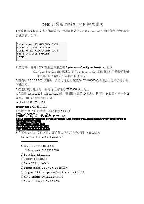
2440开发板烧写WinCE镜像注意事项
OEMMultiBINNotify: Download BIN file information: ----------------------------------------------------[0]: Base Address=0x8C200000 Length=0x12C406C ----------------------------------------------------OEMVerifyMemory: StartAddr: 0x8C200000, Length:0x12C406C *** Downloading BIN image type *** TFTP: Desktop losing ACK, block number = 5113, Ack again TFTP: Desktop losing ACK, block number = 28650, Ack again TFTP: Desktop losing ACK, block number = 28651, Ack again TFTP: Desktop losing ACK, block number = 35365, Ack again TFTP: Desktop losing ACK, block number = 35365, Ack again rom_offset=0x0. Found pTOC signature. ROMHDR at Address 8C200044h RomHdr.ulRAMStart=8E800000h RomHdr.physfirst=8C200000h. ::OEMLaunch, ImageStart:0x8C200000, ImageLength:0x12C406C, LaunchAddr:0x8C201000 EbootWaitForHostConenct Got EDBG_CMD_JUMPIMG Got EDBG_CMD_CONFIG, flags:0x0000000F Enabling debug messages over Ethernet, IP: 192.168.1.103, port:1085 Enabling CESH over Ethernet, IP: 192.168.1.103, port:1086 Enabling KDBG over Ethernet, IP: 192.168.1.103, port:1086 KitlTransport: 0x0 OEMLaunch: (IMAGE_TYPE_RAMIMAGE|IMAGE_TYPE_BINFS) +WriteRegionsToBootMedia: ImageStart: 0x8C200000, ImageLength: 0x12C406C, LaunchAddr:0x8C201000 INFO: OEMLaunch: Found chain extenstion: '' @ 0x8C200000 Writing single region/multi-region update, dwBINFSPartLength: 19677292 dwRegionStart: 0x8C200000, dwRegionLength: 0x12C406C, dwStoreOffset: 0x0 Updateded TOC! -WriteRegionsToBootMedia +TOC_Write -TOC_Write TOC {
WinCE内核动态加载GPIO端口驱动的设计方法

WinCE内核动态加载GPIO端口驱动的设计方法针对采用基于流接口驱动方式进行GPIO端口驱动开发所存在的困难和不足,提出了采用动态方式加载(卸载)端口驱动的思路,给出了该思路下GPIO端口驱动设计方法的步骤和关键代码并进行了验证,为其他类似的驱动设计与实现提供参考。
WinCE下GPIO端口驱动大多采用流接口驱动的方式进行开发,在实现上主要依托Platform Builder编译环境将驱动程序编译成动态链接库,并整合到WinCE内核中。
但在实际项目的开发中,Platform Builder在驱动程序的开发和涮试上不够便捷,且在整合动态链接库和WinCE内核时,需要进行繁琐的参数配置,整个过程较为复杂。
笔者以飞凌S3C2440开发板为例,给出在VisualStudio 编译环境中采用动态加载方式来设计GPIO端口驱动程序的思路,较好地改进了目前常用的GPIO端口驱动设计方法,提高了开发效率。
1 GPIO端口的流驱动设计1.1 过程简述关于GPIO端口流驱动的设计原理,大量论文及书籍中均有介绍,这里不再赘述。
其设计步骤也遵循固定的设计模式,按照编写驱动实现代码、驱动程序配置、编译调试的顺序进行。
1.1.1 编写驱动实现代码WinCE流式驱动实质上是按照固定的流函数接口实现的一个动态链接库。
在实现时,创建相关的.cpp文件、.h文件和.def文件,根据需要实现xxx_Init、xxx_Read、xxx_Write等流接口函数即可。
1.1.2 驱动程序配置WinCE配置文件分为源代码配置文件和镜像配置文件,通过这两种配置文件,Platform Builder编译环境实现对驱动代码和内核的编译、整合。
具体包括:①创建相关提供注册信息的.reg文件以供在WinCE注册表中注册GPIO 驱动程序。
②在Platform Builder的相关目录下,配置Dirs文件、Makefile文件、Sources文件和Platform.bib文件中的相关参数,Platform Buil der在编译时按照配置的参数编译驱动程序并将其整合到内核镜像中。
FL2440烧写WINCE问题实录
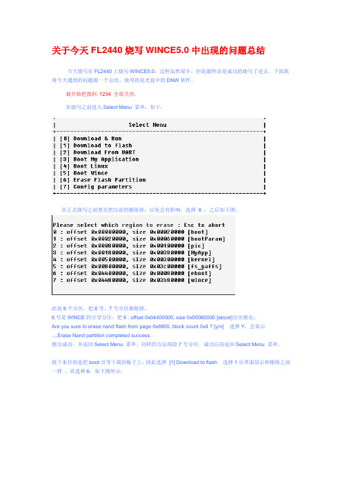
关于今天FL2440烧写WINCE5.0中出现的问题总结今天烧写在FL2440上烧写WINCE5.0,过程虽然艰辛,但是最终还是成功的烧写了进去。
下面我将今天遇到的问题做一个总结。
使用的是光盘中的DNW软件。
最开始把拨码1234 全部关闭。
在烧写之前进入Select Menu 菜单,如下,在正式烧写之前要先把以前的擦除掉,以免会有影响。
选择6 ,之后如下图。
此处8个分区,把6号、7号分区擦除掉。
6号是WINCE的引导分区,把6 : offset 0x04400000, size 0x00080000 [eboot]分区擦出,Are you sure to erase nand flash from page 0x8800, block count 0x4 ? [y/n] 选择Y。
会显示....Erase Nand partition completed success擦出成功,并返回Select Menu 菜单。
同样的方法探险7号分区。
成功后再返回Select Menu 菜单。
接下来目的是把boot引导下载到板子上,因此选择[1] Download to flash 选择1后界面显示和擦除之前一样,再选择6,如下图所示,从USB Port-->transmit 中选择eboot.nb0下载,成功后如下图。
此时已成功把eboot.nb0烧到板子中,但是还没有完成。
关闭电源,接下来把拨码开关12打开,34关闭(否则烧写时烧不进去)。
打开电源,会自动进入WINCE 的引导,会有5秒的选择配置时间,在5秒内按空格进入配置,如下图。
按空格后,出现配置选项。
如下图选择F格式化,格式化成功如下图再选择9 格式化,成功后如下图选择U USB下载xin.bin到板子中,同样通过USB Port-->transmit 来选择bin文件。
如图此时等待一会就出现如下图到此时,还是继续等待,但是此处等待时间较长,我有开始还以为是卡住了,按了复位,后来才知道是因为等待时间不够长。
浅淡WINCE环境下操作ARM芯片GPIO的方法
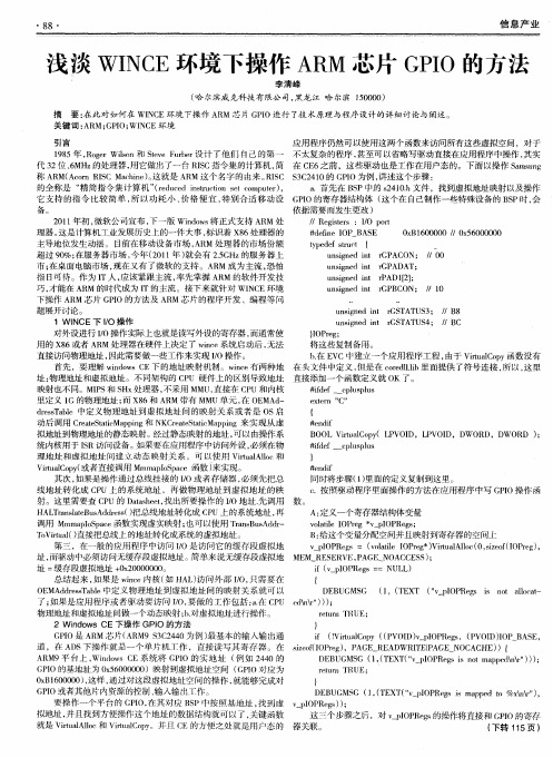
8 8・
信息产 业
浅淡 WI C N E环境下操作 A M芯 片 G I R PO的方法
李 清峰
( 尔 滨威 克 科技 有 限公 司 , 龙 江 哈 尔滨 10 0 ) 哈 黑 5 0 0
摘 要 : 此 对 如何 在 WI C 在 N E环 境 下 操 作 A M 芯 片 G I 行 了技 术 原 理 与程 序 设 计 的详 细 讨 论 与 阐 述 。 R PO进 关 键 词 : R G I WI C A M; PO; N E环 境
应用程序仍然可以使用这两个函数来访问所有这些虚拟空间 ,对于 18 95年 , oe l n和 S v ub r 计 了 他 们 自己 的 第 一 不太复杂 的程序 , R grWio s t eF re 设 e 甚至可 以省略写驱动直接在应用程序中操作 , 其实 代 3 位 、M 的处理器 , 2 6 Hz 用它做 f了一台 R S } J IC指令集的计算机 , 在 C 6 简 E 之前 ,这些驱动也是工作在用户态的。下面以操作 S m u g a sn 称 A M( cr IC Mah e 。 就是 A M 这 个 名 字 的 由来 。 IC ¥ C 4 0的 G I R A on RS ci )这 n R RS 3 2 1 PO为例 , 讲述这个步骤 : a . 首先 在 B P中 的 s4 0 的 全称 是 “ 简 指 令 集 计 算 机 ”rd cd i t co e cm u r , 精 (eu e n r t n st o p t ) su i e S 2 1. 件 ,找 到 虚 拟地 址 映 射 以及 操 作 h文 它支持 的指 令 比较简单 , 以功耗 小 、 所 价格便 宜 , 特别合适 移动设 G I PO的寄存器结构体 ( 这个在 自己制作 一些特殊设 备的 B P时 , S 会 备。 依 据需 要 而发 生 更 改 ) / /Re itr : IO p r gse s / ot 2 1 年初 , 01 微软公 司宣布 , 版 Widw 将正式支持 A M处 下一 no s R #de ne I i f OP_BAS E Ox 60 00 / 0 56 00 0 B1 00 / x 0 00 理器 。 这是计算机工业发展历史上的一件大事 , 标识着 X 6 8 处理器的 主导 地 位发 生 动 摇 。 目前 在 移 动设 备 市 场 , R 处 理 器 的市 场 份 额 A M tp d fs u t { ye e t c r un ine it r sg d n GPACON ; / /O0 超 过 9 %; 0 在服 务 器 市场 , 年 (0 1 ) 会 有 2 G z 服务 器 上 今 21年 就 . H 的 5 市 ; 面 电脑 市 场 , 在 又有 了微 软 的支 持 。A M 成 为 主 流 , 怕 在桌 现 R 恐 u sg e n r ADA n i n d it GP T; 指 日可待。作为 Ⅱ 人 , 应该紧跟 主流 , 率先掌握 A M 的软件开发技 R u s e n r A 2 ; n i d i P D1 ] n g t 1 un i n d n r sg e it GPBCON; / 1 / 0 巧, 才能在 A M 的时代成为 I R T的主流 。接下来就针对 WI C N E环境 下操 作 A M 芯 片 G I 方 法 及 A M 芯 片 的程 序 开 发 、编程 等 问 R PO的 R 题展 开讨 论 。 un in d i t r TATUS3; / sg e n GS /B8
基于S3C2440与Windows CE的手持终端设计与开发的开题报告

基于S3C2440与Windows CE的手持终端设计与开发的开题报告一、选题背景现代社会中,信息化已经成为了一种趋势和生活方式,随着智能手机、平板电脑等智能移动设备的普及,人们对于智能移动设备的需求越来越高,并呈现快速发展的趋势。
这些智能移动设备的普及,大大促进了移动互联网的发展,成为了人们进行各种信息沟通、交流和获取的主要方式。
手持终端作为智能移动设备的一种,因其功能强大、便携性高、操作简便等特点,成为了各行业、领域中必不可少的终端设备。
尤其是在商业、物流、医疗、金融等领域中,手持终端得到了广泛的应用,大大提高了工作效率和服务质量。
因此,手持终端的设计与开发具有重要的实际意义。
二、选题意义本课题将以S3C2440芯片和Windows CE操作系统为基础,设计一款功能强大、性能稳定、应用广泛的手持终端。
通过该手持终端,用户可以实现物流、仓储、库存管理、数据采集等多种功能。
该手持终端的设计与开发,具有如下意义:1、进一步提升智能移动设备的应用水平和推广率;2、提高商业、物流、医疗、金融等领域中工作效率和服务质量;3、促进智能终端设备的产业发展和技术进步;4、提升我国在移动终端市场竞争中的地位和影响力;5、拓展本人软硬件设计与开发的技能和水平。
三、研究目标本课题的主要研究目标如下:1、基于S3C2440芯片和Windows CE操作系统,设计出一款具有高性能和可扩展性的手持终端;2、探索实现物流、仓储、库存管理、数据采集等应用的方法和技术,提高手持终端的实用性和应用范围;3、了解和研究手持终端的硬件和软件设计、开发及测试方法和技巧,提高本人综合能力和技能水平。
四、研究内容本课题的主要研究内容如下:1、S3C2440芯片和Windows CE操作系统的研究及应用;2、手持终端的硬件设计与制作;3、手持终端的软件设计与编程;4、手持终端的测试与调试。
五、研究方法本课题将采取如下研究方法:1、文献资料法:通过查阅文献和资料,了解和研究S3C2440芯片和Windows CE操作系统的相关知识和技术;2、实验法:通过实验,研究手持终端的硬件和软件设计、开发及测试方法和技巧;3、模拟法:通过模拟手持终端的各种应用场景和运行情况,对手持终端的性能和稳定性进行评估和改进。
极品2440开发板wince用户手册

极品2440开发板 wince用户手册V1.0安装 4.2 BSP for 极品2440开发板1-1 在开发的主机上安装Platform Builder 4.2开发环境。
(这里假设安装目录为E:\WINCE420)1-2 插入配套开发资料光盘,拷贝开发资料光盘中的wince\SMDK2440目录中的内容到E:\WINCE420\PLATFORM\SMDK2440目录中1-3 由于开发资料光盘中的文件及目录具有只读属性,因此我们要将刚才拷贝到E:\WINCE420\PLATFORM\SMDK2440目录中的文件以及目录(包含子目录下的文件以及目录)的只读属性除去。
1-4 运行Platform Builder 4.2,如下图1-5 选择 “File”菜单下的“Manage Catalog Features⋯”菜单项,如下图:1-6 在 Catalog 列表中, 点击右边的 Import 按钮,如下图:smdk2440.cec 文件,如下图:击“OK”按钮,如下图:1-9 同样在 Catalog 列表中, 点击右边的 Import 按钮,如下图:dm9000.cec 文件,如下图:击“OK”按钮,如下图:如下图:二、在 Platform Builder 4.2 中基于新 BSP 创建一个新的Platform 并生成新的 Image 文件2-1 在 Platform Builder 下,点击 “FILE”菜单下的 “New Paltform”,如下图:2-2 在 New Platform Wizard – Step1 对话框中,选择 “Next”,如下图:2-3 在 New Platform Wizard – Step2 对话框中,选择新安装的 BSP - SMDK2440,点击“Next”,如下图:2-4 在New Platform Wizard – Step3 对话框中,在 Available configurations 中选择 Mobile Handheld , 在 Platform name 中输入 MDS522 ,点击 “Next”,如下图:2-5 在New Platform Wizard – Step4 对话框中,选中如下图中的几项应用,点击 “Next”:2-6 在New Platform Wizard – Step5 对话框中,保持默认选项不变,点击 “Next” 按钮,如下图:2-7 在New Platform Wizard – Step6 对话框中,保持默认选项不变,点击 “Next”,如 下图:2-8 在New Platform Wizard – Step7 对话框中,点击“Finish”按钮。
armsys2440开发套件wince用户手册
ARMSYS2440 开发套件WinCE用户手册(Ver 1.0)杭州立宇泰电子有限公司目 录本文涉及的软件工具: (3)1.安装W INDOWS BSP (4)1.1拷贝SMDK2440 (4)1.2进入[ File | Manage Catalog Features ]菜单项 (5)1.3导入新的smdk2440.cec (6)2.建立基于ARMSYS2440的P LATFORM (7)2.1新建Platform (7)2.2设置并添加Platform特性 (11)2.3编译Platform (21)3.通过以太网下载固化W INDOWS CE (23)3.1固化引导程序 (23)3.2下载运行Eboot.nb0 (30)3.3配置与PB的通讯 (34)3.4开始通讯下载 (36)3.5写入并启动WinCE (37)4.在P LATFORM B UILDER中导出SDK (39)4.1配置SDK (39)4.2编译SDK (42)4.3安装SDK (43)5.利用A CTIVESYNC建立W IN CE与PC机的连接 (48)5.1新建USB连接 (48)5.2设置PC连接 (49)5.3安装USB设备驱动 (50)5.4 激活Activesync连接 (51)6.在E MBEDDED V ISUAL C++中建立应用程序 (53)6.1新建工程 (53)6.2与SDK关联 (58)6.3编译并下载 (59)6.4运行 (61)附录A:所支持的设备及测试方法: (62)A.1支持RTC日历时钟 (62)A.2支持CS8900作为主控制器的网口 (63)A.3支持COM1串口 (64)A.4支持1主1从USB口 (64)A.5支持64MB NandFlash (65)A.6支持SD/MMC卡 (65)A.7具有电源管理功能(系统挂起) (66)A.8支持2个外部按键 (66)A.9 4线电阻式触摸屏 (66)A.10支持UDA1341音频设备 (66)A.11支持液晶显示设备 (66)A.12支持摄像头模块 (66)感谢使用立宇泰电子生产的ARMSYS2440系列产品!ARMSYS2440是一个二次开发平台,在它上面已经运行了一个经过移植和整理的WinCE操作系统的手持设备方案,应用程序开发工程师可以直接将他们的应用程序交叉编译后下载到ARMSYS2440上观看运行效果。
ARM2440 WinCE 5.0 VGA CAN单板机 说明书
2007 ARM2440 WinCE 5.0 VGA/CAN 单板机使用说明书 song 广州市微嵌计算机科技 2007-1-21ARM2440 WinCE 5.0 VGA 单板机目录 系统图 ....................................................................................................................... 4 功能概述 ................................................................................................................... 4 硬件概述 ................................................................................................................... 4 应用领域 ................................................................................................................... 5 工作条件 ................................................................................................................... 5 PCB图及端口介绍..................................................................................................... 6 各端口位置 ........................................................................................................ 6 串口及扩展口 .................................................................................................... 7 通用输入输出接口(GPIO) ............................................................................ 8 触摸屏接口 ........................................................................................................ 9 显示器信号线定义 ........................................................................................... 10 触摸屏的校准 .................................................................................................. 12 CAN Bus接口 .................................................................................................. 13 PCB板尺寸.............................................................................................................. 14 PC机上开发WinCE应用程序.................................................................................. 14 准备步骤 .......................................................................................................... 14 eVC++开发抓图 ............................................................................................. 15 Labview开发 .................................................................................................. 20 .net开发抓图 ................................................................................................... 23 重新安装WINCE内核.............................................................................................. 28 1. 安装USB驱动程序:..................................................................................... 29 2. 运行EBOOT格式化NandFlash删除原来的WINCE: ................................ 29广州市微嵌计算机科技 电话: 020-********2007-1-21ARM2440 WinCE 5.0 VGA 单板机3.下载WINCE内核到SDRAM:......................................................................... 31 附录 A .................................................................................................................... 32 保存注册表 ...................................................................................................... 32 开机运行自己的应用程序................................................................................ 33 安装.net2.0 Framework ................................................................................ 34广州市微嵌计算机科技电话: 020-********2007-1-21ARM2440 WinCE 5.0 VGA 单板机系统图 ARM2440 WinCE 5.0 VGA 单板机系统图功能概述 集成有以太网控制器,串口,SD 卡控制器,USB Host 控制器,声波触摸屏驱 动。
SBC2440-IIIIV用户手册-WinCE篇

SBC2440-III/IV开发指南-WinCE篇Rev. 1.0Release: 2008-08-25Contact informationFor additional information, please visit: http ://Timll Technic Inc..Revision history Rev DateDescription01 20080825 Initial version目录第1章安装WINCE5.0开发环境 (3)第2章安装SBC2440BSP包 (10)第3章用SBC2440 BSP生成可运行映象 (13)3.1 创建SBC2440工程 (13)3.2 添加各类特性 (21)第4章下载并烧写映象文件 (28)4.1 安装giveio 驱动 (28)4.2 烧写bootloader (28)4.2.1 使用EasyICE烧写Bootloader (28)4.2.2 使用Embest仿真器烧写Bootloader (33)4.3 使用eboot烧写wince image (33)第5章 SBC2440-III/IV WINCE使用 (36)5.1 触摸屏校准 (36)5.2 按键使用 (36)5.3 上网设置 (37)5.4 建立Wince平台和PC的连接 (37)5.5 使用Platform builder导出SDK (39)5.6 应用程序开发 (44)5.6.1 Embedded visual c++安装 (44)5.6.2 安装SBC2440 SDK (51)5.6.3 Hello World应用程序示例 (55)附录A 利用仿真器烧写Bootloader (64)附录B EBOOT下载菜单选项说明 (65)附录C 安装USB驱动 (66)附录D 通过网络接口下载NK (70)附录E 系统启动信息 (74)Timll Technic Inc..第1章安装WINCE5.0开发环境要定制WinCE5.0操作系统,必须安装WinCE5.0相应的开发环境。
EM2440-II WinCE User Manual
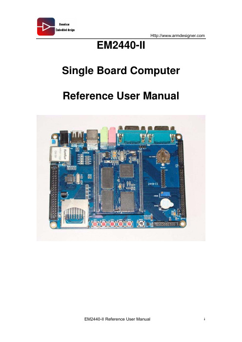
EM2440-II Single Board Computer Reference User Manual1. Introduction1.1. About this ManualThis manual is intended to provide the user with an overview of the board and benefits, complete features specifications, and set up procedures. It contains important safety information as well.1.2. Feedback and Update to this ManualTo help our customers make the most of our products, we are continually making additional and updated resources available on the Boardcon website ().These include manuals, application notes, programming examples, and updated software and hardware. Check in periodically to see what’s new!When we are prioritizing work on these updated resources, feedback from customers is the number one influence, If you have questions, comments, or concerns about your product or project, please no hesitate to contact us at support@.1.3. Limited WarrantyBoardcon warrants this product to be free of defects in material and workmanship for a period of one year from date of buy. During this warranty period Boardcon will repair or replace the defective unit in accordance with the following process:A copy of the original invoice must be included when returning the defective unit to Boardcon. This limited warranty does not cover damages resulting from lighting or other power surges, misuse, abuse, abnormal conditions of operation, or attempts to alter or modify the function of the product.This warranty is limited to the repair or replacement of the defective unit .In no event shall Boardcon be liable or responsible for any loss or damages, including but not limited to any lost profits, incidental or consequential damages, loss of business, or anticipatory profits arising from the use or inability to use this products.Repairs make after the expiration of the warranty period are subject to a repair charge and the cost of return shipping. Please contact Boardcon to arrange for any repair service andto obtain repair charge information.1. WINCE (4)1.1.H OW TO S TART WINCE (4)1.2.H OW TO USE SD CARD (5)1.3.U SE W INDOWS M EDIA P LAYER TO PLAY MP3 AND VIDEO (6)1.4.H OW TO BROWSE W EBSITE (6)1.5.C REATE CONNECTION BETWEEN W IN CE DEVICE AND PC (7)1.5.1. Install driver (7)1.5.2. User Microsoft ActiveSync (8)1.6.C HECK AND MODIFY W IN CE REGISTER (11)1.7.R UN APPLICATION (12)2. WINDOWS CE DEVELOPMENT (13)2.1.I NSTALL W INCE BPS OF EM2440-II (13)2.2.U PDATE D EVELOPMENT E NVIRONMENT (PB5) (15)2.3.N EW PROJECT (15)2.4.K ERNEL D EVELOPMENT (20)2.4.1. Add Mouse and Keyboard (21)2.4.2. Add U-Disk (22)2.4.3. Add SD Card (23)2.4.4. Add registry saved function (23)2.4.5. Add Photo Viewer (25)2.4.6. Add MP3&MP4 (26)2.5.C OMPILE THE PROJECT INTO W INDOWS CE IMAGE (26)2.6.W IZARD SDK (27)2.7.I NSTALL E MBEDDED V ISUAL C++4.0 (29)2.8.I NSTALL SP4 (32)1. WinCE1.1. How to Start WINCEThe EM2440-II board preload with WinCE operating system, select ‘5’ from bootloader to boot WinCEUser can set the Bootloader parameter to boot from WinCE when power on the board; set the value of parameter ‘0’ to 3 (Set the parameter value 2 to boot from Linux). Set the value of parameter ‘1’ to set the delay time of the startup.1.2. How to use SD cardInsert the SD card before startup the system, after WinCE start we can find SDMEM from ‘my device’1.3. Use Windows Media Player to play MP3 and videoWe preload WinCE operating system with Media Player, double click the media and video file to play.1.4. How to browse WebsiteAfter WinCE start, click “My device”Æ “Control panel” Æ”Network connection”, single click the right key of the mouse to CS89001Æ “ Properties”, then set the pop-up network setting window to use IE browse internet.1.5. Create connection between WinCE device and PCUser can use some tools which provide by Microsoft, after some necessary setting, then install WinCE operating system and create connection between the device (with WinCE) and the Windows desktop PC. Then realize file upload download and remote debug.1.5.1. Install driverAfter WinCE startup, use USB cable to connect USBDEVICE and USB port of the PC. When connection be created, the system will display “ New hardware is found”, then user install driver from WinCE BSP (WINCE500/platform/ok2440/Drivers/USB/FUNCTION), install the USB driver then operate as below:Select the location of the driver.1.5.2. User Microsoft ActiveSync1. Install Microsoft ActiveSync which is at the directory ofDVD-ROM\tools\Activesync\Microsoft ActiveSync 4.5.msi. Double click the file to beinstalled. The user also can download the file from Microsoft website.2. Set ActiveSync, select FileÆConnection Settings, it will pop up a window. Thenselect the second and the third option. Maybe it will conflict with DNW when selectthe first option which is “allow serial cable or infrared connection to this COM port”,so at here we do not suggest the customer to select the first option. Below pictureshows the operation.3. ActiveSync can be set connection via serial interface, USB interface and Ethernetinterface. This manual only takes USB interface as example to build ActiveSync connection. Normally Wince5.0 has already configured well ActiveSync, the user also can configure ActiveSync again with following stepsa. Connect the Host PC with the USB device interface of EM2440-II through USB cable.After check the connection is good, then start EM2440-II. Execute following steps on the EM2440-II. Click My computerÆcontrol panel Æ Network and Dial-up ConnectionsÆNew connection, in the setting dialog box, select the connection type as “direct connection”, please see below picture:b. Change the connection name as “My USB connection”, the click “next step”, select“S3C2440 USB cable” in the following popped up drop-down list. Click “finish”, then it will appear “My USB connection” icon, below picture shows the icon.Come back to “Control Panel”, click “pc connection”, open “pc connection’s attribute”, Select the "Enable desktop computer with a direct connection" check box, and then click on "Change connection" button, please see below picture.c. In the "Change connection" Settings dialog box drop-down list box, select just the new connection "My USB connection", and then click "OK" key to exit. The setting will be completed.c. Finally restart EM2440-II, ActiveSync is automatically building connection. Aftersuccessful connection, ActiveSync icon will turn into another color. Then, open the menu FileÆExplore, you can browse WINCE system resources, you can also copy / paste files between EM2440-II and host PC. Below picture shows the step.1.6. Check and modify WinCE registerAfter the successful connection in ActiveSync, click on PB “Tools” Æ”Remote Registry Editor menu” to run the remote registry management program, this program can remotely edit the registry of mobile devices.First select the device which we had found in the past, click “OK”. Below picture shows the step.Then it can check or edit Wince register.Note: when EM2440-II does not successfully connect the network device, the form on the above picture there is only one “My Computer”, this is EM2440-II's registry1.7. Run applicationIf you compiled with your own written Wince application i EVC or EVB, you can click on "tools"Æ"Configure platform manager" to complete the configuration for Platform Manager, then click the “Run button”, the application is sent to the board for running. In addition, the user also can use the explorer of ActiveSync, the explorer will upload the application to the EM2440-II for be run.2. Windows CE Development2.1. Install Wince BPS of EM2440-IIFirst copy the WINCE BSP package of “OK2440.rar” to the folder of “platform” which is under WinCE5.0 installation path (Our Wince5.0 installation path here for E: \ WINCE500 \ PLATFORM \), and decompress the BSP, after decompression it will appear a new folder OK2440 (E: \ WINCE500 \ PLATFORM \ OK2440).Then open edit tools of Platform Builder 5.0, run “Platform Builder 5.0”, then click “File”Æ”Manage Catalog Features”, it will pop up below catalog management window,Then click “Import”, open wince420\platform\ok2440, then select file “OK2440.CEC”, and click “open” to import the file.After imported the file, it will see “OK2440:ARMV4I” in the catalog viewer of Platform Builder 5.0. Just like below picture.2.2. Update Development Environment (PB5)So far, Microsoft is updating the WinCE and Platform Builder all the time, the user can download the newest patch from below link./downloads/results.aspx?pocId=&freetext=Windows%20CE%20 5.0%20Platform%20Builder%20Update&DisplayLang=enNote: If want WinCE to support .Net2.0, it must update the Environment.2.3. New projectRun Platform Builder 5.0, and click “File”Æ”New Platform”, it will pop up a window of “New Platform Wizard – Step 1”, click “next” to enter into next step. Below picture shows this step.It will pop up the second window of “New Platform Wizard – Step 2”, input “OK2440” (The user can also use your liked or appointed name), after clicking ‘next” to enter into next step. Below picture shows this step.It will pop up the third window of “New Platform Wizard – Step 3”,please select the option of “OK2440:ARMV4I” in the four options, then click ‘next” to enter into next step. Below picture shows this step.It will pop up the forth window of “New Platform Wizard – Step 4”,please select the optionof “Mobile Handheld” in the list of “ Available design teplates”, then click ‘next” to enter into next step. Below picture shows this step.It will pop up the fifth window of “New Platform Wizard – Step 5”,please select application & Media that you need, then click ‘next” to enter into next step. Below picture shows this step.It will pop up the sixth window of “New Platform Wizard – Step 6”,please select Networking & Communication that you need, then click ‘next” to enter into next step. Below picture shows this step.Click “next”, then you will see below picture.Click “Next”, you will see a window of “Completing the New Platform Wizward”, Click “Finish” to finish the work.The next step is to set platform of Platform Builder 5.0, click Platform ÆSetting, configure the popped up settings dialog box as below picture,The next step is, in the “locale” tab select the language of Chinese or English, below picture shows the step.2.4. Kernel DevelopmentOn our last chapter, we introduced how to new project, this chapter will introduce how to add modules in the new project.First expand the catalog list in the right side of the new project, click right mouse key to select “Add to OS Design” on the module that you are going to be added.2.4.1. Add Mouse and Keyboard2.4.2. Add U-Disk2.4.3. Add SD Card2.4.4. Add registry saved functionIf the user wants to realize to save the registry change function, it needs to add below module.2.4.5. Add Photo Viewer2.4.6. Add MP3&MP42.5. Compile the project into Windows CE imageAfter finished project setting and adding driver module, then click “Build OSÆ Sysgen” to start compile the project, below picture shows the step.After compiled, it will generate two binary image: “NK.BIN” and “NK.nb0”. Normally this two files are located at the directory of “WINCE500\PUBLIC\[PlatformName]\ RelDir\OK2440_ARMV4 Release”.2.6. Wizard SDKRun Platform Builder 5.0, and open the EM2440-II platformClick “Platform”Æ”SDK”Æ “New SDK…”, it will pop up below diagram.Click ‘Next” , Input Name and manufacture name of SDK in the diagram of “product Properties”,Click “Next”, Select “eMedded Visual C++ 4.0” and “.Net Compare Framework” in diagram of “Development languages”.Click “Next” and “Finish” to finish the SDK installation.Select “PlatformÆSDKÆBuild SDK…” to start build SDK. The SDK is at the directory of “\WINCE500\PBWorkspaces\OK2440\SDK\EM2440-III_SDK.msi”,This is a standard SDK. Double-click the file to start SDK.2.7. Install Embedded Visual C++ 4.0Embedded Visual C++ is abbreviated eVC, which is a integrated Development Environment for building Windows CE application. So far its newest version is Embedded Visual C++4.0 + Service Pack 4 (Microsoft did not update Embedded Visual C++ since Microsoft Visual Studio .NET 2005 released, all Windows CE applications are developed based on Microsoft Visual Studio .NET 2005), the user can develop Wince32,MFC,ATL and other application based on Embedded Visual C++.Here simply introduce EVC installation steps.2.8. Install SP4After installed EVC4.0, it needs to install Service Pack 4. Below table is eVC version corresponding to Windows application versioneVC Version Windows CE Application Version Embedded Visual C++ 3.0 Windows CE 3.0Embedded Visual C++ 4.0 Windows CE .NET 4.0Embedded Visual C++ 4.0 +SPI Windows CE .NET 4.1Embedded Visual C++ 4.0 +SP2/SP3 Windows CE .NET 4.2Embedded Visual C++ 4.0 +SP4 Windows CE .NET 5.0For EM2440-II, install Embedded Visual C++ 4.0 +SP4, below simply introduce installation SP4.。
S3C2440的GPIO口

S3C2440的GPIO口GPIOGPIO,通用输入输出(General Purpose I/O)的简称,其引脚可以供编程使用。
嵌入式系统中常常有数量众多,但是结构却比较简单的外部设备,对这些设备的控制,有时只需要一位控制信号就够了,即只需要开/关两种状态就够了,比如灯亮与灭。
对这些设备的控制,使用传统的串行口和并行口都不合适。
所以在微控制器芯片上一般都会提供一个“通用可编程I/O接口”,即GPIO。
S3c GPIOS3c2440有130个GPIO口,分为A到J共9组:GPA、GPB、GPC...GPJ。
通过设置相应寄存器,可以选择某个GPIO口是用于输入、输出还是其他特殊功能。
例如可以设置GPH6作为一般的输入、输出端口,或者用于串口。
操作GPIO每组GPIO(GPA~GPJ),都可以通过3个寄存器来控制与访问,这3个寄存器分别为:1.GPxCON:GPIO配置寄存器。
2.GPxDAT:GPIO数据寄存器。
3.GPxUP:上拉电阻控制寄存器。
(其中x为:A、B....H、J)GPxCON寄存器从寄存器的名字可以看出它属于配置(Confugure)寄存器——选择GPIO口的功能。
其中PORTA与PORTB~PORTJ在功能选择方面有所不同。
GPACON中每一位对应一个IO口(共23个)。
当某位为0时,相应的IO为输出;当某位被置为1时,相应的引脚为地址线或用于地址控制。
PORTB~PORTJ在寄存器操作方面完全相同,GPxCON 中每两位控制一个引脚:00表示输入,01表示输出,10表示特殊功能,11保留不用。
GPxDAT寄存器GPxDAT寄存器用于读/写引脚:当引脚被设置为输入时,读此寄存器可知相应引脚电瓶状态是高还是低;当引脚被设为输出时,写此寄存器相应的位可令此引脚输出高电平或低电平。
GPxUP寄存器GPxUP:某位为1时,相应引脚无内部上拉电阻;为0时相应的引脚使用内部上拉电阻。
(上拉电阻:由于管脚悬空比较容易受到外界的电磁干扰,因此通过一个电阻来将此管脚与高电平相连,让其固定在高电平,这样的电阻称之为上拉电阻。
2440 WinCE操作GPIO
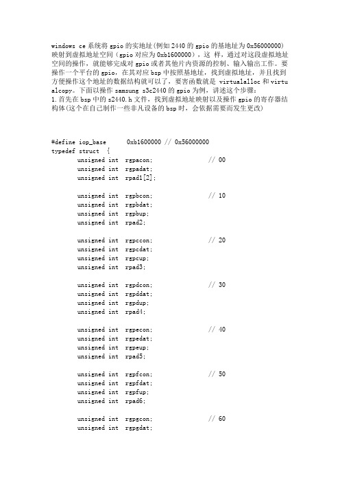
windows ce系统将gpio的实地址(例如2440的gpio的基地址为0x56000000)映射到虚拟地址空间(gpio对应为0xb1600000),这样,通过对这段虚拟地址空间的操作,就能够完成对gpio或者其他片内资源的控制、输入输出工作。
要操作一个平台的gpio,在其对应bsp中按照基地址,找到虚拟地址,并且找到方便操作这个地址的数据结构就可以了,要害函数就是 virtualalloc和virtu alcopy。
下面以操作samsung s3c2440的gpio为例,讲述这个步骤:1.首先在bsp中的s2440.h文件,找到虚拟地址映射以及操作gpio的寄存器结构体(这个在自己制作一些非凡设备的bsp时,会依据需要而发生更改)#define iop_base 0xb1600000 // 0x56000000typedef struct {unsigned int rgpacon; // 00unsigned int rgpadat;unsigned int rpad1[2];unsigned int rgpbcon; // 10unsigned int rgpbdat;unsigned int rgpbup;unsigned int rpad2;unsigned int rgpccon; // 20unsigned int rgpcdat;unsigned int rgpcup;unsigned int rpad3;unsigned int rgpdcon; // 30unsigned int rgpddat;unsigned int rgpdup;unsigned int rpad4;unsigned int rgpecon; // 40unsigned int rgpedat;unsigned int rgpeup;unsigned int rpad5;unsigned int rgpfcon; // 50unsigned int rgpfdat;unsigned int rgpfup;unsigned int rpad6;unsigned int rgpgcon; // 60unsigned int rgpgdat;unsigned int rgpgup;unsigned int rpad7;unsigned int rgphcon; // 70unsigned int rgphdat;unsigned int rgphup;unsigned int rpad8;unsigned int rmisccr; // 80unsigned int rdckcon;unsigned int rextint0;unsigned int rextint1;unsigned int rextint2; // 90unsigned int reintflt0;unsigned int reintflt1;unsigned int reintflt2;unsigned int reintflt3; // a0unsigned int reintmask;unsigned int reintpend;unsigned int rgstatus0; // acunsigned int rgstatus1; // b0unsigned int rgstatus2; // b4 ;;; shlunsigned int rgstatus3; // b8unsigned int rgstatus4; // bcunsigned int rfltout; // c0unsigned int rdsc0;unsigned int rdsc1;unsigned int rmslcon;unsigned int rgpjcon; // d0unsigned int rgpjdat;unsigned int rgpjup;unsigned int rpad9;}iopreg;二、因为我用的mini2440开发板的gpb0接在蜂鸣器上,所以我以操作gpb0为例编写代码。
S3C2440 GPIO LED 控制最简单代码
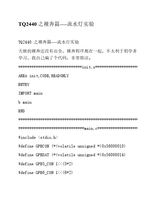
TQ2440 之裸奔篇----流水灯实验 天嵌的裸奔还没有出全,裸奔程序都在一起,不太利于初学者 学习,我自己编了个代码,非常简洁。 *****************************init.s**************************** AREA init,CODE,READONLY ENTRY IMPORT main b main END *************************************************************** ******************************main.c*************************** #include <stdio.h> #define GPBCON (*(volatile unsigned *)0x56000010) #define GPBDAT (*(volatile unsigned *)0x56000014) #define GPB5_CON 1<<(5*2) #define GPB6_CON 1<<(6*2)
rGPBDAT=~Bit(i);
41
Delay();
42
}
43
}
44 }
45 此后,可以直接下载至内存中执行,不过掉电后丢失;或者下载到
NANDFlash中,上电后,s3c2440自动copyNANDFlsh前4K的代码到
内存中,并从内存起始地址0x30000000开始执行程序。
delay();
GPBDAT=~(1<<8);//GPB8为0 LED4 亮
delay();
}
}
LT2440-WinCE 6.0开发手册

陆通网络科技有限公司WinCE6.0开发手册发布日期2012.02.15版权所有©陆通网络科技有限公司。
保留一切权利。
非经本公司书面许可,任何单位和个人不得擅自摘抄、复制本文档内容的部分或全部,并不得以任何形式传播。
您购买的产品、服务或特性等应受本公司商业合同和条款的约束,本文档中描述的全部或部分产品、服务或特性可能不在您的购买或使用范围之内。
除非合同另有约定,海思公司对本文档内容不做任何明示或默示的声明或保证。
由于产品版本升级或其他原因,本文档内容会不定期进行更新。
除非另有约定,本文档仅作为使用指导,本文档中的所有陈述、信息和建议不构成任何明示或暗示的担保。
陆通网络科技有限公司地址:湖南长沙岳麓区潇湘中路麓枫和苑网址:修订记录修订记录累积了每次文档更新的说明。
最新版本的文档包含以前所有文档版本的更新内容。
目录目录 (4)第一章WinCE6.0开发环境建立 (1)1.WinCE6.0开发系列软件下载 (1)2.VS2005及SP1安装 (2)2.1安装VS2005 (2)2.2安装vs2005sp1 (5)3.WinCE6.0以及补丁安装 (6)3.1安装WinCE6.0 (6)3.2安装WinCE6.0SP1 (10)3.3安装WinCE6.0R2 (13)3.4安装wince6.0R3 (16)3.5安装WinCE6.0R3Rollup (19)3.6安装WinCE6.0Rollup补丁包 (21)3.7安装Mobile QQ (22)4.安装LT2440WinCE6.0BSP包 (25)4.1安装LT2440BSP包 (25)4.2安装基于VS2005的WinCE6.0项目文件 (26)第二章WinCE6.0系统编译 (28)1.基于现成项目文件的系统编译 (28)2.新建项目文件及编译 (35)3.完全编译和快速编译 (49)4.WinCE6.0系统烧写 (49)第三章WinCE6.0系统和应用测试 (56)1.WinCE6.0系统测试 (56)1.1LCD旋转测试 (57)1.2helloworld (57)1.3录音测试 (58)1.4LED测试 (58)1.5网络设置 (58)1.6FTP测试 (60)1.7WEB Server测试 (61)1.8telnet测试 (62)1.9U盘测试 (64)1.10SD卡测试 (65)2.第三方应用程序可以自行下载,进行测试 (65)第一章WinCE6.0开发环境建立WinCE6.0的安装十分繁琐,并且对开发主机性能有较高要求(否则安装过程会很慢,请耐心等待)。
基于S3C2440与WinCE平台上的FIQ驱动程序的实现
基于S3C2440与WinCE平台上的FIQ驱动程序的实现开元海;汪超;郑勇【期刊名称】《微型机与应用》【年(卷),期】2012(031)024【摘要】在简述WinCE系统中普通IRQ中断处理过程的基础上,针对采用普通IRQ中断的驱动程序实时性能不高的问题,提出使用ARM处理器的FIQ中断在实时性能要求较高的场合中的应用方法。
系统硬件部分使用ARMS3C2440处理器作为主控部分,软件部分开发出WinCE5.0操作系统下使用FIQ中断针对步进电机驱动器的驱动程序。
实践证明,驱动程序使用FIQ中断是稳定的且能获得比IRQ中断更好的实时性能。
%Based on the brief introduction of general IRQ interrupt processing in WinCE system and the less real-time performance of the driver used IRQ interrupt, this paper put forward the method of using FIQ interrupt of ARM processor to achieve higher performance requirements in real time applications. The system uses ARM $3C2440 processor as the main control unit. The driver use FIQ interrupt for stepping motor driver was developed under the WinCE5.0 operating system. Practice has proved that the driver using the FIQ interrupt is stable and can obtain better performance than using IRQ interrupt.【总页数】3页(P89-91)【作者】开元海;汪超;郑勇【作者单位】贝加莱工业自动化西安分公司,陕西西安710075;台州职业技术学院机电工程学院,浙江台州318000;安徽省滁州市第一职业高级中学,安徽滁州239002【正文语种】中文【中图分类】TP316.2【相关文献】1.基于 WinCE 的模拟键盘驱动程序的实现 [J], 吴弋晻;葛海江;张能贵2.基于WinCE下NDIS小端口驱动程序的设计与实现 [J], 石启国3.基于S3C2440的触摸屏驱动程序实现 [J], 强新建;田泽;刘天时4.基于WinCE环境的CAN适配卡驱动程序的设计与实现 [J], 杨军波;须文波5.基于WinCE环境的CAN总线扩展卡驱动程序的设计与实现 [J], 杨清华因版权原因,仅展示原文概要,查看原文内容请购买。
- 1、下载文档前请自行甄别文档内容的完整性,平台不提供额外的编辑、内容补充、找答案等附加服务。
- 2、"仅部分预览"的文档,不可在线预览部分如存在完整性等问题,可反馈申请退款(可完整预览的文档不适用该条件!)。
- 3、如文档侵犯您的权益,请联系客服反馈,我们会尽快为您处理(人工客服工作时间:9:00-18:30)。
计算机基本知识windows ce系统将gpio的实地址(例如2440的g pio的基地址为0x56000000)映射到虚拟地址空间(gpio对应为0xb1600000),这样,通过对这段虚拟地址空间的操作,就能够完成对gpio或者其他片内资源的控制、输入输出工作。
要操作一个平台的gpio,在其对应bsp中按照基地址,找到虚拟地址,并且找到方便操作这个地址的数据结构就可以了,要害函数就是 virtualalloc和virtualcopy。
下面以操作samsung s3c2440的gpio为例,讲述这个步骤:
1.首先在bsp中的s2440.h文件,找到虚拟地址映射以及操作gpio的寄存器结构体(这个在自己制作一些非凡设备的bsp时,会依据需要而发生更改)
#define iop_base 0xb1600000 // 0x56000000
typedef struct {
unsigned int rgpacon; // 00
unsigned int rgpadat;
unsigned int rpad1[2];
unsigned int rgpbcon; // 10
unsigned int rgpbdat;
unsigned int rgpbup;
unsigned int rpad2;
unsigned int rgpccon; // 20
unsigned int rgpcdat;
unsigned int rgpcup;
unsigned int rpad3;
unsigned int rgpdcon; // 30
unsigned int rgpddat;
unsigned int rgpdup;
unsigned int rpad4;
unsigned int rgpecon; // 40
unsigned int rgpedat;
unsigned int rgpeup;
unsigned int rpad5;
unsigned int rgpfcon; // 50
unsigned int rgpfdat;
unsigned int rgpfup;
unsigned int rpad6;
unsigned int rgpgcon; // 60
unsigned int rgpgdat;
unsigned int rgpgup;
unsigned int rpad7;
unsigned int rgphcon; // 70
unsigned int rgphdat;
unsigned int rgphup;
unsigned int rpad8;
unsigned int rmisccr; // 80
unsigned int rdckcon;
unsigned int rextint0;
unsigned int rextint1;
unsigned int rextint2; // 90
unsigned int reintflt0;
unsigned int reintflt1;
unsigned int reintflt2;
unsigned int reintflt3; // a0
unsigned int reintmask;
unsigned int reintpend;
unsigned int rgstatus0; // ac
unsigned int rgstatus1; // b0
unsigned int rgstatus2; // b4 ;;; shl
unsigned int rgstatus3; // b8
unsigned int rgstatus4; // bc
unsigned int rfltout; // c0
unsigned int rdsc0;
unsigned int rdsc1;
unsigned int rmslcon;
unsigned int rgpjcon; // d0
unsigned int rgpjdat;
unsigned int rgpjup;
unsigned int rpad9;
}iopreg;
二、因为我用的mini2440开发板的gpb0接在蜂鸣器上,所以我以操作gpb0为例编写代码。
这样给gpb0一个高电平,那么蜂鸣器就会响,反之蜂鸣器就会停止发声
#ifdef __cplusplus
extern "c"
{
#endif
bool virtualcopy( pvoid, pvoid, dword, dword );
#ifdef __cplusplus
}
#endif
void gpio() //通过gpio控制蜂鸣器
{
volatile iopreg *v_pioregs;
v_pioregs = (volatile iopreg *)virtualalloc(0, sizeof(iopreg), mem_reserve, page_noaccess);
if(v_pioregs)
{
if(virtualcopy((pvoid)v_pioregs, (pvoid)iop_base, sizeof(iopreg), page_readwrite | page_nocache))
{
v_pioregs->rgpbcon = 1; //
将gpb0设置为output
v_pioregs->rgpbdat = 0x3ff; //设置为高电平,蜂鸣器发声
sleep(3000);
v_pioregs->rgpbdat = 0; //恢复为低电平,蜂鸣器停止发声
}
virtualfree((lpvoid)v_pioregs, 0, mem_release);
v_pioregs = null;
}
}
@written by .cpp。
