LT1021DCS8中文资料
L7818C中文资料
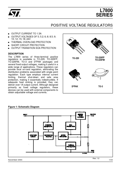
Figure 2: Schematic Diagram
2/34
L7800 SERIES
Figure 3: Connection Diagram (top view)
TO-220 (Any Type)
TO-220FP/TO-220FM
D2PAK (Any Type)
TO-3
Table 3: Order Codes
TO-220
TO-220FP TO-220FM
D2PAK
TO-3
Figure 1: Schematic Diagram
November 2004
Rev. 12
1/34
L7800 SERIES
Table 1: Absolute Maximum Ratings
Symbol VI IO Ptot Tstg Top DC Input Voltage Output Current Power Dissipation Storage Temperature Range Operating Junction Temperature for L7800 Range for L7800C Parameter for VO= 5 to 18V for VO= 20, 24V Value 35 40 Internally Limited Internally Limited -65 to 150 -55 to 150 0 to 150 °C °C Unit V
TYPE L7805 L7805C L7852C L7806 L7806C L7808 L7808C L7885C L7809C L7810C L7812 L7812C L7815 L7815C L7818 L7818C L7820 L7820C L7824 L7824C TO-220 (A Type) TO-220 (C Type) TO-220 (E Type) D2PAK (A Type) (*) D2PAK (C Type) (T & R) TO-220FP TO-220FM TO-3 L7805T L7805CT L7852CT L7806T L7806CT L7808T L7808CT L7885CT L7809CT L7812T L7812CT L7815T L7815CT L7818T L7818CT L7820T L7820CT L7824T L7824CT
1FSD08110 产品说明书

1FSD08110产品说明书概述1FSD08110是为高压大功率IGBT开发的光纤接口的高性能数字驱动器,适用于两电平及多电平变流器,数字化控制可优化IGBT开关性能,同时集成了“智能故障管理系统”,为IGBT 提供最优化的保护,其良好的EMC特性,适用于恶劣的电磁场环境,已经在新能源、轨道交通、工业传动及智能电网等各个领域广泛使用。
1FSD08110是针对140×190mm 及140×130mm封装的模块,如Infineon IHM与ABB HiPak开发的即插即用型驱动器,适用于不同产商的相同封装IGBT。
图1 产品照片目录概述 (1)系统框架图 (3)使用步骤及注意事项 (4)机械尺寸图 (5)引脚定义 (7)状态指示灯说明 (8)驱动参数 (9)主要功能说明 (12)短路保护——didt (12)短路保护——电阻 (13)欠压保护 (13)软关断 (14)数控有源钳位 (15)分级关断 (16)脉冲异常保护 (17)不会坏的驱动 (18)智能故障管理系统 (19)故障编码返回 (21)光纤口告知信号 (21)环境过温保护 (23)门极电阻位置指示 (24)订购信息 (25)技术支持 (25)法律免责声明 (25)联系方式 (25)系统框架图图2 系统框架图原边电源输入直流电压15V,通过相关电路得到系统所需的供电电压,保证系统的能量来源;PWM信号经光纤传输直接到副边,经过相关单元电路的处理得到半导体器件IGBT的驱动信号。
当门极开通时,若没有发生短路故障,则主功率器件饱和导通,IGBT-CE两端电压接近于零,IGBT-CE检测被复位,相应的软关断电路不启动;若发生短路故障,门极开通的过程中,主功率器件退出饱和,IGBT-CE两端电压接近于母线电压,IGBT-CE检测被置位,相应的软关断电路被启动来保护主功率器件不被损坏,同时故障信号经光纤传到上位机;当没有PWM信号输入时,门极则一直处于负压关断状态。
ADC081S021中文资料
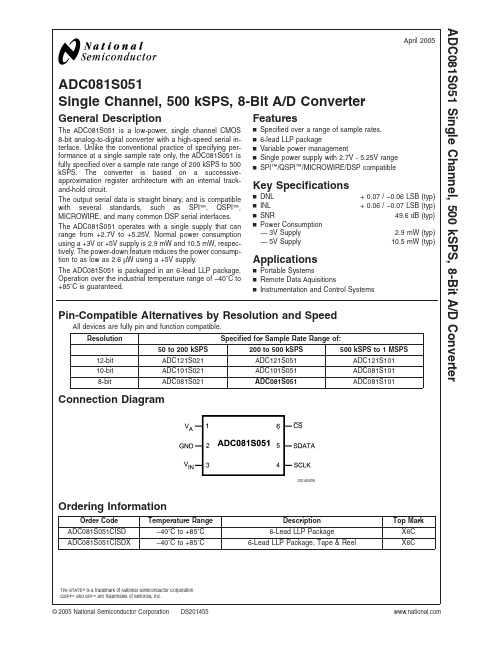
ADC081S051Single Channel,500kSPS,8-Bit A/D ConverterGeneral DescriptionThe ADC081S051is a low-power,single channel CMOS 8-bit analog-to-digital converter with a high-speed serial in-terface.Unlike the conventional practice of specifying per-formance at a single sample rate only,the ADC081S051is fully specified over a sample rate range of 200kSPS to 500kSPS.The converter is based on a successive-approximation register architecture with an internal track-and-hold circuit.The output serial data is straight binary,and is compatible with several standards,such as SPI ™,QSPI ™,MICROWIRE,and many common DSP serial interfaces.The ADC081S051operates with a single supply that can range from +2.7V to +5.25V.Normal power consumption using a +3V or +5V supply is 2.9mW and 10.5mW,respec-tively.The power-down feature reduces the power consump-tion to as low as 2.6µW using a +5V supply.The ADC081S051is packaged in an 6-lead LLP package.Operation over the industrial temperature range of −40˚C to +85˚C is guaranteed.Featuresn Specified over a range of sample rates.n 6-lead LLP packagen Variable power managementn Single power supply with 2.7V -5.25V range nSPI ™/QSPI ™/MICROWIRE/DSP compatibleKey Specificationsn DNL +0.07/−0.06LSB (typ)n INL +0.06/−0.07LSB (typ)n SNR49.6dB (typ)nPower Consumption —3V Supply 2.9mW (typ)—5V Supply10.5mW (typ)Applicationsn Portable Systemsn Remote Data Aquisitionsn Instrumentation and Control SystemsPin-Compatible Alternatives by Resolution and SpeedAll devices are fully pin and function compatible.ResolutionSpecified for Sample Rate Range of:50to 200kSPS200to 500kSPS 500kSPS to 1MSPS12-bit ADC121S021ADC121S051ADC121S10110-bit ADC101S021ADC101S051ADC081S1018-bitADC081S021ADC081S051ADC081S101Connection Diagram20145505Ordering InformationOrder Code Temperature Range Description Top Mark ADC081S051CISD −40˚C to +85˚C 6-Lead LLP PackageX6C ADC081S051CISDX−40˚C to +85˚C6-Lead LLP Package,Tape &ReelX6CTRI-STATE ®is a trademark of National Semiconductor Corporation QSPI ™and SPI ™are trademarks of Motorola,Inc.April 2005ADC081S051Single Channel,500kSPS,8-Bit A/D Converter©2005National Semiconductor Corporation Block Diagram20145507Pin Descriptions and Equivalent CircuitsPin No.SymbolDescriptionANALOG I/O3V INAnalog inputs.This signal can range from 0V to V A .DIGITAL I/O4SCLK Digital clock input.This clock directly controls the conversion and readout processes.5SDATA Digital data output.The output samples are clocked out of this pin on falling edges of the SCLK pin.6CSChip select.On the falling edge of CS,a conversion process begins.POWER SUPPLY1V A Positive supply pin.This pin should be connected to a quiet +2.7V to +5.25V source and bypassed to GND with a 1µF capacitor and a 0.1µF monolithic capacitor located within 1cm of the power pin.2GNDThe ground return for the supply and signals.A D C 081S 051 2Absolute Maximum Ratings(Notes1,2) If Military/Aerospace specified devices are required, please contact the National Semiconductor Sales Office/ Distributors for availability and specifications.Analog Supply Voltage V A−0.3V to6.5V Voltage on Any Pin to GND−0.3V to V A+0.3V Input Current at Any Pin(Note3)±10mA Package Input Current(Note3)±20mA Power Consumption at T A=25˚C See(Note4) ESD Susceptibility(Note5)Human Body Model Machine Model 3500V 300VJunction Temperature+150˚C Storage Temperature−65˚C to+150˚C Operating Ratings(Notes1,2)Operating Temperature Range−40˚C≤T A≤+85˚C V A Supply Voltage+2.7V to+5.25V Digital Input Pins Voltage Range−0.3V to V A Clock Frequency4MHz to10MHz Sample Rate up to500kSPS Analog Input Voltage0V to V APackage Thermal ResistancePackageθJA6-lead LLP78˚C/WSoldering process must comply with National Semiconduc-tor’s Reflow Temperature Profile specifications.Refer to /packaging.(Note6)ADC081S051Converter Electrical Characteristics(Note9)The following specifications apply for V A=+2.7V to5.25V,GND=0V,f SCLK=4MHz to10MHz,f SAMPLE=200kSPS to500kSPS,unless otherwise noted.Boldface limits apply for T A=T MIN to T MAX:all other limits T A= 25˚C.Symbol Parameter Conditions TypicalLimits(Note9)UnitsSTATIC CONVERTER CHARACTERISTICSResolution with No Missing Codes8BitsINL Integral Non-Linearity +0.06+0.3LSB(max)−0.07−0.3LSB(min)DNL Differential Non-Linearity +0.07+0.2LSB(max)−0.06−0.2LSB(min)V OFF Offset Error+0.03±0.2LSB(max) GE Gain Error±0.08±0.4LSB(max)TUE Total Unadjusted Error+0.8+0.2LSB(max)−0.07−0.3LSB(min)DYNAMIC CONVERTER CHARACTERISTICSSINAD Signal-to-Noise Plus Distortion Ratio V A=+2.7to5.25Vf IN=100kHz,−0.02dBFS49.649dB(min)SNR Signal-to-Noise Ratio V A=+2.7to5.25Vf IN=100kHz,−0.02dBFS49.649dB(min)THD Total Harmonic Distortion V A=+2.7to5.25Vf IN=100kHz,−0.02dBFS−70−65dB(max)SFDR Spurious-Free Dynamic Range V A=+2.7to5.25Vf IN=100kHz,−0.02dBFS6765dB(min)ENOB Effective Number of Bits V A=+2.7to5.25Vf IN=100kHz,−0.02dBFS7.97.8Bits(min)IMD Intermodulation Distortion,SecondOrder TermsV A=+5.25Vf a=103.5kHz,f b=113.5kHz−68dB Intermodulation Distortion,ThirdOrder TermsV A=+5.25Vf a=103.5kHz,f b=113.5kHz−68dBFPBW-3dB Full Power Bandwidth V A=+5V11MHzV A=+3V8MHzADC081S051 3ADC081S051Converter Electrical Characteristics(Note 9)(Continued)The following specifications apply for V A =+2.7V to 5.25V,GND =0V,f SCLK =4MHz to 10MHz,f SAMPLE =200kSPS to 500kSPS,unless otherwise noted.Boldface limits apply for T A =T MIN to T MAX :all other limits T A =25˚C.SymbolParameterConditionsTypicalLimits (Note 9)UnitsANALOG INPUT CHARACTERISTICS V IN Input Range 0to V AVI DCL DC Leakage Current ±1µA (max)C INAInput CapacitanceTrack Mode 30pF Hold Mode 4pF DIGITAL INPUT CHARACTERISTICS V IH Input High Voltage V A =+5.25V 2.4V (min)V IL Input Low Voltage V A =+5.25V 0.8V (max)V A =+3.6V 0.4V (max)I IN Input CurrentV IN =0V or V A±0.1±1µA (max)C INDDigital Input Capacitance24pF (max)DIGITAL OUTPUT CHARACTERISTICS V OH Output High Voltage I SOURCE =200µA V A −0.03V A −0.2V (min)I SOURCE =1mA V A −0.1V V OL Output Low VoltageI SINK =200µA 0.030.4V (max)I SINK =1mA0.1VI OZH ,I OZL TRI-STATE ®Leakage Current ±0.1±10µA (max)C OUTTRI-STATE ®Output Capacitance 24pF (max)Output CodingStraight (Natural)BinaryPOWER SUPPLY CHARACTERISTICS (C L =10pF)V ASupply Voltage2.7V (min)5.25V (max)I ASupply Current,Normal Mode (Operational,CS low)V A =+5.25V,f SAMPLE =200kSPS 2.0 2.4mA (max)V A =+3.6V,f SAMPLE =200kSPS 0.8 1.0mA (max)Supply Current,Shutdown (CS high)f SCLK =0MHz,V A =+5.25V f SAMPLE =0kSPS0.5µA V A =+5.25V,f SCLK =10MHz,f SAMPLE =0kSPS 22µA P DPower Consumption,Normal Mode (Operational,CS low)V A =+5.25V 10.512.6mW (max)V A =+3.6V2.93.6mW (max)Power Consumption,Shutdown (CS high)f SCLK =0MHz,V A =+5.25V f SAMPLE =0kSPS2.6µW V A =+5.25V,f SCLK =10MHz,f SAMPLE =0kSPS0.12mWAC ELECTRICAL CHARACTERISTICS f SCLK Clock Frequency (Note 8)4MHz (min)10MHz (max)f S Sample Rate (Note 8)50200kSPS (min)500kSPS (max)t CONV Conversion Time 16SCLK cycles DC SCLK Duty Cyclef SCLK =10MHz5040%(min)60%(max)t ACQTrack/Hold Acquisition Time 400ns (max)Throughput TimeAcquisition Time +Conversion Time20SCLK cyclesA D C 081S 0514ADC081S051Converter Electrical Characteristics(Note9)(Continued)The following specifications apply for V A=+2.7V to5.25V,GND=0V,f SCLK=4MHz to10MHz,f SAMPLE=200kSPS to500kSPS,unless otherwise noted.Boldface limits apply for T A=T MIN to T MAX:all other limits T A= 25˚C.Symbol Parameter Conditions TypicalLimits(Note9)UnitsAC ELECTRICAL CHARACTERISTICSt QUIET(Note10)50ns(min) t AD Aperture Delay3nst AJ Aperture Jitter30ps ADC081S051Timing SpecificationsThe following specifications apply for V A=+2.7V to5.25V,GND=0V,f SCLK=4MHz to10MHz,f SAMPLE=200kSPS to500kSPS,Boldface limits apply for T A=T MIN to T MAX:all other limits T A=25˚C.Symbol Parameter Conditions Typical Limits Units t CS Minimum CS Pulse Width10ns(min) t SU CS to SCLK Setup Time10ns(min)t EN Delay from CS Until SDATA TRI-STATE®Disabled(Note11)20ns(max)t ACC Data Access Time after SCLK Falling Edge(Note12)V A=+2.7to+3.640ns(max)V A=+4.75to+5.2520ns(max)t CL SCLK Low Pulse Width 0.4xt SCLKns(min)t CH SCLK High Pulse Width 0.4xt SCLKns(min)t H SCLK to Data Valid Hold Time V A=+2.7to+3.67ns(min) V A=+4.75to+5.255ns(min)t DIS SCLK Falling Edge to SDATA HighImpedance(Note13)V A=+2.7to+3.625ns(max)6ns(min)V A=+4.75to+5.2525ns(max)5ns(min)t POWER-UP Power-Up Time from Full Power-Down1µsNote1:Absolute Maximum Ratings indicate limits beyond which damage to the device may occur.Operating Ratings indicate conditions for which the device is functional,but do not guarantee specific performance limits.For guaranteed specifications and test conditions,see the Electrical Characteristics.The guaranteed specifications apply only for the test conditions listed.Some performance characteristics may degrade when the device is not operated under the listed test conditions.Note2:All voltages are measured with respect to GND=0V,unless otherwise specified.Note3:When the input voltage at any pin exceeds the power supply(that is,V IN<GND or V IN>V A),the current at that pin should be limited to10mA.The20mA maximum package input current rating limits the number of pins that can safely exceed the power supplies with an input current of10mA to two.The Absolute Maximum Rating specification does not apply to the V A pin.The current into the V A pin is limited by the Analog Supply Voltage specification.Note4:The absolute maximum junction temperature(T J max)for this device is150˚C.The maximum allowable power dissipation is dictated by T J max,thejunction-to-ambient thermal resistance(θJA),and the ambient temperature(T A),and can be calculated using the formula P D MAX=(T J max−T A)/θJA.The valuesfor maximum power dissipation listed above will be reached only when the device is operated in a severe fault condition(e.g.when input or output pins are drivenbeyond the power supply voltages,or the power supply polarity is reversed).Obviously,such conditions should always be avoided.Note5:Human body model is100pF capacitor discharged through a1.5kΩresistor.Machine model is220pF discharged through zero ohmsNote6:Reflow temperature profiles are different for lead-free and non-lead-free packages.Note7:Tested limits are guaranteed to National’s AOQL(Average Outgoing Quality Level).Note8:This is the frequency range over which the electrical performance is guaranteed.The device is functional over a wider range which is specified under Operating Ratings.Note9:Data sheet min/max specification limits are guaranteed by design,test,or statistical analysis.Note10:Minimum Quiet Time required by Bus relinquish and start of the next conversion.Note11:Measured with the timing test circuit shown in Figure1and defined as the time taken by the output signal to cross1.0V.Note12:Measured with the timing test circuit shown in Figure1and defined as the time taken by the output signal to cross1.0V or2.0V.Note13:t DIS is derived from the time taken by the output to change by0.5V with the timing test circuit shown in Figure1.The measured number is then adjustedto remove the effects of charging or discharging the25pF capacitor.This means that t DIS is the true bus relinquish time,independent of the bus loading.ADC081S0515Timing Diagrams20145508FIGURE 1.Timing Test Circuit20145506FIGURE 2.ADC081S051Serial Timing DiagramA D C 081S 051 6Specification DefinitionsACQUISITION TIME is the time required to acquire the input voltage.That is,it is time required for the hold capacitor to charge up to the input voltage.APERTURE DELAY is the time between the fourth falling SCLK edge of a conversion and the time when the input signal is acquired or held for conversion.APERTURE JITTER (APERTURE UNCERTAINTY)is the variation in aperture delay from sample to sample.Aperture jitter manifests itself as noise in the output.CONVERSION TIME is the time required,after the input voltage is acquired,for the ADC to convert the input voltage to a digital word.DIFFERENTIAL NON-LINEARITY (DNL)is the measure of the maximum deviation from the ideal step size of 1LSB.DUTY CYCLE is the ratio of the time that a repetitive digital waveform is high to the total time of one period.The speci-fication here refers to the SCLK.EFFECTIVE NUMBER OF BITS (ENOB,or EFFECTIVE BITS)is another method of specifying Signal-to-Noise and Distortion or SINAD.ENOB is defined as (SINAD −1.76)/6.02and says that the converter is equiva-lent to a perfect ADC of this (ENOB)number of bits.FULL POWER BANDWIDTH is a measure of the frequency at which the reconstructed output fundamental drops 3dB below its low frequency value for a full scale input.GAIN ERROR is the deviation of the last code transition (111...110)to (111...111)from the ideal (V REF −1.5LSB),after adjusting for offset error.INTEGRAL NON-LINEARITY (INL)is a measure of the deviation of each individual code from a line drawn from negative full scale (1⁄2LSB below the first code transition)through positive full scale (1⁄2LSB above the last code transition).The deviation of any given code from this straight line is measured from the center of that code value.INTERMODULATION DISTORTION (IMD)is the creation of additional spectral components as a result of two sinusoidal frequencies being applied to the ADC input at the same time.It is defined as the ratio of the power in the second and third order intermodulation products to the sum of the power in both of the original frequencies.IMD is usually expressed in dB.MISSING CODES are those output codes that will never appear at the ADC outputs.The ADC081S051is guaranteed not to have any missing codes.OFFSET ERROR is the deviation of the first code transition (000...000)to (000...001)from the ideal (i.e.GND +0.5LSB).SIGNAL TO NOISE RATIO (SNR)is the ratio,expressed in dB,of the rms value of the input signal to the rms value of the sum of all other spectral components below one-half the sampling frequency,not including harmonics or d.c.SIGNAL TO NOISE PLUS DISTORTION (S/N+D or SINAD)Is the ratio,expressed in dB,of the rms value of the input signal to the rms value of all of the other spectral compo-nents below half the clock frequency,including harmonics but excluding d.c.SPURIOUS FREE DYNAMIC RANGE (SFDR)is the differ-ence,expressed in dB,between the rms values of the input signal and the peak spurious signal where a spurious signal is any signal present in the output spectrum that is not present at the input,excluding d.c.TOTAL HARMONIC DISTORTION (THD)is the ratio,ex-pressed in dB or dBc,of the rms total of the first five harmonic components at the output to the rms level of the input signal frequency as seen at the output.THD is calcu-lated aswhere Af 1is the RMS power of the input frequency at the output and Af 2through Af 6are the RMS power in the first 5harmonic frequencies.THROUGHPUT TIME is the minimum time required between the start of two successive conversion.It is the acquisition time plus the conversion time.TOTAL UNADJUSTED ERROR is the worst deviation found from the ideal transfer function.As such,it is a comprehen-sive specification which includes full scale error,linearity error,and offset error.ADC081S0517Typical Performance CharacteristicsT A =+25˚C,f SAMPLE =200kSPS to 500kSPS,f SCLK =4MHz to 10MHz,f IN=100kHz unless otherwise stated.DNL vs Clock FrequencyINL vs Clock Frequency2014556520145566Total Adjusted Error vs Clock Frequency SNR vs Clock Frequency2014556720145563SINAD vs.Clock FrequencyPower Consumption vs.Throughput,f SCLK =10MHz2014556420145555A D C 081S 051 8Applications Information1.0ADC081S051OPERATIONThe ADC081S051are successive-approximation analog-to-digital converters designed around a charge-redistribution digital-to-analog converter.Simplified schematics of the ADC081S051in both track and hold operation are shown in Figures 3and 4,respectively.In Figure 3,the device is in track mode:switch SW1connects the sampling capacitor to the input,and SW2balances the comparator inputs.The device is in this state until CS is brought low,at which point the device moves to hold mode.Figure 4shows the device in hold mode:switch SW1con-nects the sampling capacitor to ground,maintaining the sampled voltage,and switch SW2unbalances the compara-tor.The control logic then instructs the charge-redistribution DAC to add or subtract fixed amounts of charge from the sampling capacitor until the comparator is balanced.When the comparator is balanced,the digital word supplied to the DAC is the digital representation of the analog input voltage.The device moves from hold mode to track mode on the 13th rising edge of SCLK.2.0USING THE ADC081S051The serial interface timing diagram for the ADC081S051is shown in Figure 2.CS is chip select,which initiates conver-sions on the ADC081S051and frames the serial data trans-fers.SCLK (serial clock)controls both the conversion pro-cess and the timing of serial data.SDATA is the serial data out pin,where a conversion result is found as a serial data stream.Basic operation of the ADC081S051begins with CS going low,which initiates a conversion process and data transfer.Subsequent rising and falling edges of SCLK will be labelled with reference to the falling edge of CS;for example,"the third falling edge of SCLK"shall refer to the third falling edge of SCLK after CS goes low.At the fall of CS,the SDATA pin comes out of TRI-STATE,and the converter moves from track mode to hold mode.The input signal is sampled and held for conversion on the falling edge of CS.The converter moves from hold mode to trackmode on the 13th rising edge of SCLK (see Figure 2).The SDATA pin will be placed back into TRI-STATE after the 16th falling edge of SCLK,or at the rising edge of CS,whichever occurs first.After a conversion is completed,the quiet time t QUIET must be satisfied before bringing CS low again to begin another conversion.Sixteen SCLK cycles are required to read a complete sample from the ADC081S051.The sample bits (including any leading or trailing zeroes)are clocked out on falling edges of SCLK,and are intended to be clocked in by a receiver on subsequent falling edges of SCLK.The ADC081S051will produce three leading zero bits on SDATA,followed by eight data bits,most significant first.After the data bits,the ADC081S051will clock out four trailing zeros.If CS goes low before the rising edge of SCLK,an additional (fourth)zero bit may be captured by the next falling edge of SCLK.20145509FIGURE 3.ADC081S051in Track Mode20145510FIGURE 4.ADC081S051in Hold ModeADC081S0519Applications Information(Continued)3.0ADC081S051TRANSFER FUNCTIONThe output format of the ADC081S051is straight binary.Code transitions occur midway between successive integer LSB values.The LSB width for the ADC081S051is V A /256.The ideal transfer characteristic is shown in Figure 5.The transition from an output code of 00000000to a code of 00000001is at 1/2LSB,or a voltage of V A /512.Other code transitions occur at steps of one LSB.4.0TYPICAL APPLICATION CIRCUITA typical application of the ADC081S051is shown in Figure 6.Power is provided in this example by the National Semi-conductor LP2950low-dropout voltage regulator,available in a variety of fixed and adjustable output voltages.The power supply pin is bypassed with a capacitor network located close to the ADC081S051.Because the reference for the ADC081S051is the supply voltage,any noise on the supplywill degrade device noise performance.To keep noise off the supply,use a dedicated linear regulator for this device,or provide sufficient decoupling from other circuitry to keep noise off the ADC081S051supply pin.Because of the ADC081S051’s low power requirements,it is also possible to use a precision reference as a power supply to maximize performance.The four-wire interface is also shown con-nected to a microprocessor or DSP .20145511FIGURE 5.Ideal Transfer Characteristic20145513FIGURE 6.Typical Application CircuitA D C 081S 051 10Applications Information(Continued)5.0ANALOG INPUTSAn equivalent circuit for one of the ADC081S051’s input channels is shown in Figure 7.Diodes D1and D2provide ESD protection for the analog inputs.At no time should any input go beyond (V A +300mV)or (GND −300mV),as these ESD diodes will begin conducting,which could result in erratic operation.The capacitor C1in Figure 7has a typical value of 4pF,and is mainly the package pin capacitance.Resistor R1is the on resistance of the multiplexer and track /hold switch,and is typically 500ohms.Capacitor C2is the ADC081S051sam-pling capacitor and is typically 26pF.The ADC081S051will deliver best performance when driven by a low-impedance source to eliminate distortion caused by the charging of the sampling capacitance.This is especially important when using the ADC081S051to sample AC signals.Also important when sampling dynamic signals is a band-pass or low-pass filter to reduce harmonics and noise,improving dynamic performance.6.0DIGITAL INPUTS AND OUTPUTSThe ADC081S051digital inputs (SCLK and CS)are not limited by the same absolute maximum ratings as the analog inputs.The digital input pins are instead limited to +6.5V with respect to GND,regardless of V A ,the supply voltage.This allows the ADC081S051to be interfaced with a wide range of logic levels,independent of the supply voltage.7.0MODES OF OPERATIONThe ADC081S051has two possible modes of operation:normal mode,and shutdown mode.The ADC081S051en-ters normal mode (and a conversion process is begun)whenCS is pulled low.The device will enter shutdown mode if CS is pulled high before the tenth falling edge of SCLK after CS is pulled low,or will stay in normal mode if CS remains low.Once in shutdown mode,the device will stay there until CS is brought low again.By varying the ratio of time spent in the normal and shutdown modes,a system may trade-off throughput for power consumption.7.1Normal ModeThe fastest possible throughput is obtained by leaving the ADC081S051in normal mode at all times,so there are no power-up delays.To keep the device in normal mode con-tinuously,CS must be kept low until after the 10th falling edge of SCLK after the start of a conversion (remember that a conversion is initiated by bringing CS low).If CS is brought high after the 10th falling edge,but before the 16th falling edge,the device will remain in normal mode,but the current conversion will be aborted,and SDATA will return to TRI-STATE (truncating the output word).Sixteen SCLK cycles are required to read all of a conversion word from the device.After sixteen SCLK cycles have elapsed,CS may be idled either high or low until the next conversion.If CS is idled low,it must be brought high again before the start of the next conversion,which begins when CS is again brought low.After sixteen SCLK cycles,SDATA returns to TRI-STATE.Another conversion may be started,after t QUIET has elapsed,by bringing CS low again.7.2Shutdown ModeShutdown mode is appropriate for applications that either do not sample continuously,or it is acceptable to trade through-put for power consumption.When the ADC081S051is in shutdown mode,all of the analog circuitry is turned off.To enter shutdown mode,a conversion must be interrupted by bringing CS back high anytime between the second and tenth falling edges of SCLK,as shown in Figure 8.Once CS has been brought high in this manner,the device will enter shutdown mode;the current conversion will be aborted and SDATA will enter TRI-STATE.If CS is brought high before the second falling edge of SCLK,the device will not change mode;this is to avoid accidentally changing mode as a result of noise on the CS line.20145514FIGURE 7.Equivalent Input Circuit20145516FIGURE 8.Entering Shutdown ModeADC081S05111Applications Information(Continued)To exit shutdown mode,bring CS back low.Upon bringing CS low,the ADC081S051will begin powering up (power-up time is specified in the Timing Specifications table).This microsecond of power-up delay results in the first conversion result being unusable.The second conversion performed after power-up,however,is valid,as shown in Figure 9.If CS is brought back high before the 10th falling edge of SCLK,the device will return to shutdown mode.This is done to avoid accidentally entering normal mode as a result of noise on the CS line.To exit shutdown mode and remain in normal mode,CS must be kept low until after the 10th falling edge of SCLK.The ADC081S051will be fully powered-up after 16SCLK cycles.8.0POWER MANAGEMENTThe ADC081S051takes time to power-up,either after first applying V A ,or after returning to normal mode from shut-down mode.This corresponds to one "dummy"conversion for any SCLK frequency within the specifications in this document.After this first dummy conversion,the ADC081S051will perform conversions properly.Note that the t QUIET time must still be included between the first dummy conversion and the second valid conversion.When the V A supply is first applied,the ADC081S051may power up in either of the two modes:normal or shutdown.As such,one dummy conversion should be performed after start-up,exactly as described in the previous paragraph.The part may then be placed into either normal mode or the shutdown mode,as described in Sections 7.1and 7.2.When the ADC081S051is operated continuously in normal mode,the maximum throughput is f SCLK /20.Throughput may be traded for power consumption by running f SCLK at its maximum 10.0MHz and performing fewer conversions per unit time,putting the ADC081S051into shutdown modebetween conversions.A plot of typical power consumption versus throughput is shown in the Typical Performance Curves section.To calculate the power consumption for a given throughput,multiply the fraction of time spent in the normal mode by the normal mode power consumption and add the fraction of time spent in shutdown mode multiplied by the shutdown mode power consumption.Generally,the user will put the part into normal mode and then put the part back into shutdown mode.Note that the curve of power consumption vs.throughput is nearly linear.This is because the power consumption in the shutdown mode is so small that it can be ignored for all practical purposes.9.0POWER SUPPLY NOISE CONSIDERATIONSThe charging of any output load capacitance requires cur-rent from the power supply,V A .The current pulses required from the supply to charge the output capacitance will cause voltage variations on the supply.If these variations are large enough,they could degrade SNR and SINAD performance of the ADC.Furthermore,discharging the output capaci-tance when the digital output goes from a logic high to a logic low will dump current into the die substrate,which is resis-tive.Load discharge currents will cause "ground bounce"noise in the substrate that will degrade noise performance if that current is large enough.The larger the output capaci-tance,the more current flows through the die substrate and the greater is the noise coupled into the analog channel,degrading noise performance.To keep noise out of the power supply,keep the output load capacitance as small as practical.If the load capacitance is greater than 25pF,use a 100Ωseries resistor at the ADC output,located as close to the ADC output pin as practical.This will limit the charge and discharge current of the output capacitance and improve noise performance.20145517FIGURE 9.Entering Normal ModeA D C 081S 051 12。
S9S08DZ128资料翻译

MC9S08DZ128MC9S08DZ96MC9S08DV128MC9S08DV96数据手册HCS08微处理控制器MC9S08DZ128第一版2008年5月飞思卡尔半导体MC9S08DZ128系列产品的特性8位HCSO8中央处理单元(CPU)•40-MHz HCS08 CPU(20-MHz总线)•HC08指令集,带附加的BGND指令•支持最多32个中断/复位源片内存储器•整个工作电压和温度范围内可读取/编程/擦除的Flash存储器•最大2K的EEPROM在线可编程内存;支持8字节单页或4字节双页擦除分区;执行Flash程序的同时可进行编程和擦除操作;支持擦除取消操作节能模式•两种非常低功耗停止模式•Reduced power wait mode降低功耗等待模式•超低功耗实时中断,在运行、等待和停止模式下均可操作时钟源选项•振荡器(XOSC)—闭环控制的皮尔斯(Pierce)振荡器;支持范围31.25 kHz至38.4 kHz或1 MHz至16MHz之间的晶体或陶瓷谐振器•多功能时钟生成器(MCG)—PLL和FLL模式(在使用内部温度补偿时FLL能够达到1.5%内的偏差);带微调功能的内部参考时钟源;带可选择晶体振荡器或陶瓷谐振器的外部参考时钟源系统保护•监视微控制器(计算机)看门狗(COP)复位,支持备用专用1KHZ的内部时钟源或总线时钟操作的选项。
带有可选择的视窗化得操作•带复位和中断的低压检测电路;可选择的电压阀值•支持非法指令代码复位•支持非法操作地址复位•支持Flash与EEPROM块保护•支持时钟信号丢失保护开发支持•单线背景调试接口•总线实时捕获功能的上及在线仿真(ICE)外围设备•ADC(模数转换)24通道- 12位分辨率, 2.5μs转换时间, 自动比较功能,温度传感器,包含内部能兮参考源通道•ACMPx—两个模拟比较器,支持比较器输出的上升,下降或任意边缘触发的中断;可选择与内部能隙参考电压源比较;运行在STOP3模式;•MSCAN— CAN协议- Version 2.0 A, B; 支持标准和扩展数据帧;支持远程帧;5个带FIFO 存储框架的接收缓冲器;灵活的接收识别符过滤器,可编程如下:2 x 32位、4 x 16位或8 x 8位•SCIx—两个SCI,可支持LIN 2.0协议和SAE J2602协议;全双工;主节点支持break 信号生成;从节点支持break信号检测;支持激活边沿唤醒•SPIx—多达两个SPIs;全双工或单线双向;双重缓冲发送与接受;主从模式; 支持高位优先或低位优先的移动•IICx—多达两个IICs; 支持最高100kps的总线负载; 多主节点模式运行;可编程的从地址; 通用呼叫地址; 逐字节传输驱动的中断r•TPMx—一个6通道(TPM1), 一2通道(TPM2)和一个4通道(TPM3);可支持输入捕捉, 输出比较, 或每个通道带缓冲的边沿对齐PWM输出。
DCS MI8 中文教程手册

中央面板:
设置所需的 VHF 频率
打开雷达高度表: RADIOVYS(雷达高度表功率)- UP
打开俯仰和侧倾稳定性增强俯仰/滚动绿色推光- 短按 LWIN+A
飞行的直升机
起飞 由于 MI-8配备了一个轮式底盘,它可以起飞 或垂直滚动发车后,运行的起飞。正在运行的起飞 可以用来获得一些初步的空速时,直升机太重而提 垂直起飞。表演起飞可以是具有挑战性的,因为他们需要在第一 环状,踏板,协调,持续,平稳控制 集体所有。
DCS MI8 中文教程手册
本手册根据 ED 开发商定制的原教程基础上我把英文翻译成中文。 里面有不对的地 方请大家多谅解。本翻译由 3GO*SN-1858
直升机控制 初级直升机飞行控制系统,包括循环控制杆,集体 控制杆,反扭矩踏板。的循环是等效的操纵杆 并用于提高或降低它的鼻子和滚动直升机左,右侧为 原来。集体位于由飞行员的一侧和向上移动和向下 控制的升程量,本质上用的主旋翼产生的 获得或失去高度(爬升/下降) 。踏板是用来打开(偏航) 鼻子的左边或右边沿地平线以最小的辊,可用于旋转 直升机悬停时。 从驾驶舱飞行时,可以切换控制指标显示 按 RCTRL+ Enter 可看到你的位置的视觉参考 飞行控制系统。学习如何飞翔时,这可以是非常有帮助的。
要开始起飞,释放驻车制动,按 W 。直升机的 鼻子可能会开始晃动,车轮被释放。使用非常轻微的踏板 循环的修正,以保持鼻子直和稳定。 集体开始提高非常缓慢。通常需要的环状 被拉到稍稍向后和向右(在每个方向上的10%至20%左右) ,以 保持一个稳定的心态。右踏板也需要压在大约10-20%的方式,以防止直升机偏航左边 是集体 增加。继续慢慢提高集体和使用仔细棒和 踏板控制,以保持鼻子的位置,并尽量减少任何滑动沿 在地面上。做得正确时,直升机会慢慢抬离地面, 悬停到一个稳定的,低海拔最低的位置和方向的变化。 轻微右岸角度有必要保持悬停位置 防止向左滑动。 升空到离地面几英尺的高空后,稍微压低机头 通过释放一定的背压棒开始加速前进。
LDEDC2180中文资料

LDE Series
PEN -- PET H.T. PRODUCT CODE SYSTEM
The part number, comprising 14 digits, is formed as follows:
1 2 3 4 5 6 7 8 9 10 11 12 13 14 L D E
50Vdc/40Vac
size code 18.12 18.12 18.12 18.12 18.12 18.12 18.12 18.12 18.12 18.12 18.12 18.12 18.12 18.12 18.12 18.12 18.12 18.12 18.12 18.12 18.12 18.12 18.12 18.12 18.12 18.12 18.12 18.12 18.12 22.20 22.20 22.20 22.20 22.20 22.20 28.24 28.24 28.24 50.40 50.40 50.40 50.40 60.54 60.54 60.54 H max 1.7 1.7 1.7 1.7 1.7 1.7 1.7 1.7 1.7 1.7 1.7 1.7 1.7 1.7 1.7 1.7 1.7 1.7 1.7 1.7 2.3 2.3 2.3 2.3 2.3 1.7 1.7 2.3 2.3 2.3 2.3 2.3 2.3 3.3 3.3 3.5 3.5 3.5 3.6 3.6 3.6 4.5 4.5 4.5 4.9 Part Number LDECC1100 - -5- LDECC1120 - -5- LDECC1150 - -5- LDECC1180 - -5- LDECC1220 - -5- LDECC1270 - -5- LDECC1330 - -5- LDECC1390 - -5- LDECC1470 - -5- LDECC1560 - -5- LDECC1680 - -5- LDECC1820 - -5- LDECC2100 - -5- LDECC2120 - -5- LDECC2150 - -5- LDECC2180 - -5- LDECC2220 - -5- LDECC2270 - -5- LDECC2330 - -5- LDECC2390 - -5- LDECC2470 - -5- LDECC2560 - -5- LDECC2680 - -5- LDECC2820 - -5- LDECC3100 - -5- LDECC3120 - -5- LDECC3150 - -5- LDECC3180 - -5- LDECC3220 - -5- LDECD3270 - -5- LDECD3300 - -5- LDECD3390 - -5- LDECD3470 - -5- LDECD3560 - -5- LDECD3680 - -5- LDECE3820 - -5- LDECE4100 - -5- LDECE4120 - -5- LDECG4150- -5- LDECG4180- -5- LDECG4220- -5- LDECG4270- -5- LDECH4330 - -5- LDECH4390 - -5- LDECH4470 - -5- -
DCS Mi-8MTV2 米8直升机 中文飞行手册 驾驶舱系统和控制 动力装置和直升机系统控制和指示器

为了帮助设定起飞时的额定转子转速为95%,总控制手柄具有N2微调增量-减小开关,以允许逐渐调整发动机动力涡轮机转速。
5.3.动力装置和直升机系统控制和指示器5.3.1.ИТЭ-2Т(ITE-2t)双发动机转速表双转速表用于监测每台发动机的压缩机(N1)转速。
转速表示为最大转速的百分比。
“1”指针表示左发动机转速,“2”指针表示右发动机转速。
刻度范围为0-110%,刻度为1%。
转速表位于飞行员仪表板的左下方。
第二个发动机双转速表位于副驾驶的仪表板上。
转速表从安装在发动机附件驱动器上的转速表发电机接收动力,每个发动机上一个。
图5.20.飞行员和副驾驶的双发动机转速表5.3.2.ИТЭ-1Т(ITE-1T)主转子转速表转速表位于飞行员仪表板的左中心区域。
主转子转速计用于监测主转子转速。
转速表示为最大转速的百分比。
第二个主旋翼转速表位于副驾驶仪表板的右中心区域。
转速表从安装在主变速箱上的转速表发电机接收电力。
刻度范围为0-110%,刻度为1%。
图5.21.飞行员和副驾驶的主旋翼转速表5.3.3.ЭМИ-3РИ (EMI-3RI ) 发动机机油压力/温度表发动机机油压力/温度表(每个发动机一个)安装在中控台上。
这个量表有三个刻度。
未使用上刻度。
左下刻度以0至8 kg/cm2的刻度显示机油压力。
右下方的刻度以摄氏度显示机油温度,刻度为-70°C至+150°C。
图5.22.机油压力/温度表,中控台5.3.4.ЭМИ-3РВИ (EMI-3RVI)三指针驱动系统油压/温度表驱动系统机油压力和温度表安装在中控台上部左侧。
这个量表有三个刻度。
上刻度显示主变速箱中的机油压力,单位为kg/cm2。
左下刻度显示中间齿轮箱中的机油温度,右下刻度显示尾转子齿轮箱中的机油温度。
86图5.23.三指针驱动系统机油压力/温度表,中控台仪表接收安装在变速箱齿轮箱上的机油温度探针的温度指示。
压力指示由变速箱油系统中的压力传感器提供。
D-Link DCS-2121 说明书

目录包装清单....... (1)最低系统要求 (2)说明 (3) (4)特性和优势....................................................................................................................................硬件总览..... . (5)硬件安装 (7)连接天线............ .. (7)连接摄像设备 (7)连接以太网线缆 (8)连接电源适配器 (8)软件安装............... .. (9)安装安装精灵软件 (14)使用安装精灵 (17) (21)使用ffdshow ................................................................................................................................调整摄像头焦距 (24)使用WPS来安装无线连接 (25)使用配置菜单 (26)实施视频 (27)实时视频 > 摄像机 (27)安装 (28)安装> 安装精灵............................................................................................................................................................................................................ (28)安装> 网络安装 (29)安装> 无线............................................................................................................................ . (30)安装> 动态DNS (31)安装>镜像安装 (32)安装> 音频和视频............ (33)安装> 活动探测 (35)安装> 时间和日期 ...................................................................................................................... .. (36)安装> 记录 (37)安装> 抓拍 (39)安装> 数字输入 (41)维护............ . (42)维护> 设备管理 (42)维护> 备份和恢复 (43)维护> 固件升级 (44)状态 (45)状态>设备信息 (45)状态> 日志......................................................................................................................... . (46)帮助 (47).. (48)在路由器下安装 DCS-2121............ .........................................................................................................1)在网络上识别你的摄像设备................. . (48)2) 分配用于你的摄像设备的本地IP地址和端口 (49)3)打开HTTP端口....................................................................................................................... (50)4) 打开虚拟服务器端口来启用远程镜像查看 (52)在Internet上查看你的摄像设备 (53)在路由器下基于Internet 查看你的摄像设备 (53)常见问题 (54) (54)Internet摄像设备特性.....................................................................................................................................Internet摄像设备安装 (55) (57)怎样Ping你的IP地址时间区域表 (59)DI/DO输入技术规格 (60)技术规格 (61)包装清单如果丢失包裹中的任意一种物品,请与您的零售商联系。
SCM8故障(带温度)指示器
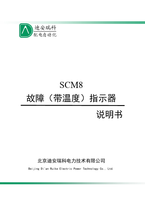
SCM8 故障(带温度)指示器 说明书北京迪安瑞科电力技术有限公司Beijing Di'an Ruike Electric Power Technology Co., Ltd.SCM8 型故障(带温度)指示器SCM8 型故障(带温度)指示器供货清单 序号 1 2 3 4 5 6 7 产品名称故障指示器主机 接地传感器 二合一传感器 信号传输光纤 使用说明书规格型号SCM8 型 SCM8 型 SCM8 型 通用型 专用型数量1台 1只 3只 4根 1份备注北京迪安瑞科竭诚为广大电力用户 提供全面的配电技术支持与服务安全、方便、准确的智能电网配电解决方案SCM8 型故障(带温度)指示器 一、产品简介短路--故障A B CA相 接地B相 超温C相SCM8SCM8 型故障(带温度)指示器是配套安装在配电网络系统中的环网开关柜、 电缆分支箱、箱变上,用于指示相应电缆区段的短路、单相接地、电缆头超温故 障的一种实时监测装置。
线路发生故障时,工作人员可借助指示器的报警指示, 迅速确定故障区段,并找出故障点。
同时,报警信息可实时发送到监控中心的服 务器,在监控电脑的屏幕上显示出故障所在的区域和具体位置,引导巡线人员迅 速确定故障区段并找出故障点。
该指示器为解决故障查找问题提供了最佳途径。
对提高工作效率,缩短停电时间,迅速恢复供电,提高供电可靠性和经济效益, 有着十分重要的意义。
二、故障检测装置组成序号 A B C D 名称 SCM8 故障指示器主机 标准型接地传感器 短路、温度二合一传感器 信号传输光纤 数量 1台 1只 3只 4× 3 米-1-SCM8 型故障(带温度)指示器 三、主要功能1. 短路报警指示:短路传感器在工作中检测线路的电流,当线路发生短路故障 且故障电流达到或超过报警电流整定值时,短路传感器发出报警信号,通过光纤 传输给主机,主机接收到此信号后,产生相应的报警指示信号。
2. 接地报警指示:接地传感器在工作中检测线路的零序电流,当线路发生接地 故障且接地故障电流达到或超过报警电流整定值时,接地传感器发出报警信号, 通过光纤传输到主机,主机接收到此信号后,产生相应的报警指示信号。
SinoMCU 8位单片机MC32F7122用户手册说明书

SinoMCU 8位单片机MC32F7122用户手册V1.1上海晟矽微电子股份有限公司Shanghai SinoMCU Microelectronics Co., Ltd.目录1产品概要 (4)1.1产品特性 (4)1.2订购信息 (5)1.3引脚排列 (6)1.4端口说明 (6)2电气特性 (8)2.1极限参数 (8)2.2直流电气特性 (8)2.3交流电气特性 (9)2.4ADC特性参数 (9)2.5比较器特性参数 (10)2.6OPA特性参数 (10)2.7EEPROM特性参数 (10)3CPU及存储器 (11)3.1指令集 (11)3.2程序存储器 (13)3.3数据存储器 (14)3.4在线编程 (15)3.5堆栈 (16)3.6控制寄存器 (16)3.7用户配置字 (19)4系统时钟 (20)4.1内置高频RC振荡器 (20)4.2内置低频RC振荡器 (20)4.3工作模式 (21)4.4低功耗模式 (22)5复位 (23)5.1复位条件 (23)5.2上电复位 (23)5.3外部复位 (24)5.4低电压复位 (24)5.5看门狗复位 (24)6I/O端口 (25)6.1I/O工作模式 (25)6.2上/下拉电阻控制 (26)7定时器TIMER (28)7.1看门狗定时器WDT (28)7.2定时器T0 (28)7.3定时器T1 (30)7.4定时器T2 (31)7.5定时器T3 (34)8.1PPG概述 (36)8.2PPG结构框图 (37)8.3PPG相关寄存器 (37)9模数转换器ADC (40)9.1ADC概述 (40)9.2ADC操作步骤 (41)9.3ADC相关寄存器 (41)9.4ADC零点偏移修调流程 (44)10模拟比较器CP (46)10.1比较器概述 (46)10.2比较器相关寄存器 (46)10.3比较器失调电压调校流程 (51)11运算放大器OPA (52)11.1OPA概述 (52)11.2OPA相关寄存器 (52)11.3OPA失调电压调校流程 (53)12低电压检测LVD (54)13IIC通讯接口 (55)13.1IIC概述 (55)13.2IIC相关寄存器 (55)13.3IIC通讯流程 (56)14EEPROM (58)14.1EEPROM概述 (58)14.2EEPROM相关寄存器 (58)14.3EEPROM操作示例 (59)15中断 (61)15.1外部中断 (61)15.2定时器中断 (61)15.3ADC中断 (61)15.4PPG触发中断 (62)15.5比较器中断 (62)15.6IIC通讯中断 (62)15.7LVD中断 (62)15.8中断相关寄存器 (62)16特性曲线 (66)16.1I/O特性 (66)16.2功耗特性 (69)16.3模拟电路特性 (72)17封装尺寸 (74)17.1DIP20 (74)17.2SOP16 (74)17.3DIP16 (75)18修订记录 (76)1产品概要1.1产品特性⏹8位CPU内核✧精简指令集,8级深度硬件堆栈✧CPU为双时钟,可在系统高/低频时钟之间切换✧高频时钟下F CPU可配置为2T/4T/8T/16T/32T/64T,低频时钟下F CPU固定为2T⏹程序存储器✧4K×16位FLASH型程序存储器✧可通过间接寻址读取程序存储器内容✧支持在线烧录,擦写次数至少1000次⏹数据存储器✧256字节SRAM通用数据存储器,支持直接寻址、间接寻址等多种寻址方式✧64字节EEPROM型数据存储器,支持单独烧录和软件读写,擦写次数至少10000次⏹3组共18个I/O✧P0(P00~P07),P1(P10~P17),P2(P20~P21)✧P00/P02复用成SCL/SDA时为开漏输出✧P1、P2为大电流端口✧所有端口均支持推挽输出,均内置输入上/下拉电阻且可单独使能/禁用⏹时钟系统✧内置高频RC振荡器(16MHz),可用作系统高频时钟源✧内置低频RC振荡器(32KHz),可用作系统低频时钟源⏹多种系统工作模式✧高速模式:CPU在高频时钟下运行,低频时钟源工作✧低速模式:CPU在低频时钟下运行,高频时钟源可选停止或工作✧HOLD模式1:CPU停止运行,高频时钟源工作✧HOLD模式2:CPU停止运行,高频时钟源停止工作,低频时钟源工作✧休眠模式:CPU停止运行,所有时钟源停止工作⏹内部自振式看门狗计数器(WDT)✧溢出时间可配置:64ms/2048ms✧工作模式可配置:始终开启、始终关闭、低功耗模式下停止⏹4个定时器✧8位定时器T0,可实现外部计数功能✧8位定时器T1,可实现比较器CP0输出下降沿计数功能✧8位定时器T2,可实现内/外部计数和高/低电平脉宽测量功能✧8位定时器T3,支持PPG模式(即支持单次定时且开启时禁止PPG重触发)⏹1个10位脉冲发生器PPG✧支持端口PTRIG输入电平下降沿、或比较器CP0输出的下降沿触发PPG计数;支持比较器CP2输出下降沿停止PPG计数;可通过寄存器控制位直接启动或停止PPG计数✧支持防重触发功能,支持触发去抖和触发延时功能并产生触发中断✧PPG输出有效时端口电平高/低可选,输出无效时端口为高阻态✧PPG时钟为F的1/2/4/8分频,PPG分辨率最高可达0.0625us⏹1个12位高精度ADC✧12路外部通道:AN0~AN11;2路内部通道:GND、VDD/4✧参考电压可选:VDD、内部参考电压V IR(4V)✧ADC时钟:F HIRC的8/16/32/64/128/256/512/1024分频✧支持零点校准或外部输入校准⏹4个比较器✧输入共模0V ~(VDD-1.4),支持正/负输入端偏移自消除模式(调校精度为±2mV)✧比较器CP0:正/负输入端外接,输出下降沿可触发PPG✧比较器CP1,正端16级基准电压:0.34VDD~0.64VDD/0.0625V IR~0.875V IR,分压精度1%✧比较器CP2,正端8级基准电压:0.05VDD~0.70VDD/0.425V IR~0.8V IR,分压精度1%✧比较器CP3,正端32级基准电压:0.08VDD~0.70VDD/0.1V IR~0.875V IR,分压精度1% ⏹1个运算放大器OPA✧开环放大倍数60dB✧输入共模0V ~(VDD-1.4),支持正/负输入端偏移自消除模式(调校精度为±2mV)✧内置组合电路,支持输出端作为ADC输入或比较器CP3负端输入⏹1组IIC通讯接口✧支持7位地址编码的从机模式✧通讯速率最高支持400Kbps⏹中断✧外部中断(INT0~INT1)✧定时器中断(T0~T3),ADC中断,PPG触发中断(PTRIG/CP0),比较器中断(CP1~CP3),LVD中断✧IIC通讯中断⏹低电压复位LVR:2.3V/2.7V/3.3V/4.1V⏹低电压检测LVD:3.3V/4.2V⏹工作电压✧V LVR27 ~ 5.5V @ Fcpu = 0~8MHz✧V LVR23 ~ 5.5V @ Fcpu = 0~4MHz✧V LVR23 ~ 5.5V @ Fcpu = 0~32KHz/2⏹封装形式✧DIP20/SOP16/DIP161.2订购信息产品名称封装形式备注MC32F7122A0E DIP20MC32F7122A0K SOP16MC32F7122A0C DIP161.3引脚排列MC32F7122A0EMC32F7122A0E 1DIP20234567891020191817161514131211CP0N/P04CP2N/P03[PDT]/AN0/SDA/P02[PDO]/AN1/PPG/P01[PCK]/AN2/SCL/TC2/P00AN3/PTRIG/P10AN4/P11RST/INT1/P20GND AN5/P12P05/CP0P/CP1N0/CP3N0P06/CP1N1/CP3N1/AN11P07/OPAN P17/OPAO/AN10P16/OPAP/AN9P21VDDP15/INT0/AN8P14/AN7P13/TC0/AN6MC32F7122A0K/A0CMC32F7122A0K/A0CSOP16/DIP1612345678161514131211109CP0N/P04CP2N/P03[PDT]/AN0/SDA/P02[PDO]/AN1/PPG/P01[PCK]/AN2/SCL/TC2/P00RST/INT1/P20GND AN5/P12P05/CP0P/CP1N0/CP3N0P06/CP1N1/CP3N1/AN11P07/OPAN P17/OPAO/AN10VDDP15/INT0/AN8P14/AN7P13/TC0/AN61.4 端口说明端口名称 类型 功能说明VDD P 电源 GND P 地P0,P1,P2 D GPIO ,内部上/下拉 INT0~INT1 DI 外部中断输入TC0,TC2 DI 定时器T0、T2的外部计数输入 PTRIG DI PPG 外部触发输入 PPGDOPPG 输出AN0~AN11 AI ADC输入通道CP0P,CP0N AI 比较器CP0正端、负端输入CP1N0~CP1N1 AI 比较器CP1负端输入通道0~1CP2N AI 比较器CP2负端输入CP3N0~CP3N1 AI 比较器CP3负端输入通道0~1OPAP,OPAN,OPAO A 运放OPA正端、负端输入,OPA输出SCL,SDA D IIC通讯时钟/数据端口,开漏输出RST DI 外部复位输入PCK,PDT,PDO D 编程时钟/数据端口注:P-电源,D-数字输入输出,DI-数字输入,DO-数字输出,A-模拟输入输出,AI-模拟输入,AO-模拟输出。
TI ADS7138 8通道12位ADC模块参考手册说明书

A D V A N C E I N F O R M A T I O NAIN0 / GPIO0AIN1 / GPIO1AIN2 / GPIO2AIN3 / GPIO3AIN4 / GPIO4AIN5 / GPIO5AIN6 / GPIO6AIN7 / GPIO7ALERTGNDDVDD SDA SCLADDR Device Block DiagramExample System ArchitectureOVP: Over voltage protection OCP: Over current protectionProduct Folder Order Now Technical Documents Tools &SoftwareSupport &CommunityADS7138ZHCSJS8–MAY 2019ADS7138小型8通道12位ADC ,具有I 2C 接口、GPIO 和CRC1特性•小封装尺寸:–3mm ×3mm WQFN•8通道,可配置为以下任意组合:–最多8个模拟输入、数字输入或数字输出•用于I/O 扩展的GPIO :–开漏、推挽数字输出•模拟监控:–每个通道的可编程阈值–用于瞬态抑制的事件计数器•宽工作范围:–AVDD :2.35V 至5.5V –DVDD :1.65V 至5.5V–温度范围:–40°C 至+125°C •用于读取/写入操作的CRC :–数据读取/写入CRC –上电配置CRC •I 2C 接口:–高达3.4MHz (高速)–8个可配置I 2C 地址•可编程均值滤波器:–用于求平均值的可编程样本大小–利用内部转换求平均值–用于计算平均输出的16位分辨率2应用•监控功能•便携式仪表•电信基础设施•电源监控3说明ADS7138是一款易于使用的8通道多路复用12位逐次逼近寄存器模数转换器(SAR ADC)。
8个通道可独立配置为模拟输入、数字输入或数字输出。
蓝天LT828说明书

目录
安全事项 ---------------------------------------------------------------------------------------- 5
■ 关于您的设备---------------------------------------------------------- 5
8.电话本-------------------------------------------------------------------------------------- 11
■ 联系人 --------------------------------------------------------------- 11 ■ 增加新联系人 --------------------------------------------------------- 11 ■ 设置 ----------------------------------------------------------------- 11 ■ 本机号码 ------------------------------------------------------------- 11 ■ 通话组 --------------------------------------------------------------- 11 ■ 快捷拨号 ------------------------------------------------------------- 11 ■ 删除全部联系人 ------------------------------------------------------- 11 ■ 转存联系人 ----------------------------------------------------------- 11 ■ 复制联系人 ----------------------------------------------------------- 11 ■ 黑名单 --------------------------------------------------------------- 12
LT208中文资料

MODELS CHART
INPUT MODEL NUMBER
LT101 LT102 LT103 LT104 LT105 LT106 LT107 LT108 LT201 LT202 LT203 LT204 LT205 LT206 LT207 LT208
INPUT CURRENTS VOLTAGE RAN71 77 78 77 83 83 81 83 73 82 83
NOTE: Nominal Input Voltage 12 or 24 VDC
42
元器件交易网
ELECTRICAL SPECIFICATIONS
All specifications typical at nominal line, full load and 25°C
OUTPUT SPECIFICATIONS
Single Output . . . . . . . . . . . . .±1% max. Dual+Output . . . . . . . . . . . . .±1% max. -Output . . . . . . . . . . . . . . . . .±3% max. Triple 5V . . . . . . . . . . . . . . . .±2% max. 12V/15V . . . . . . . . . . . . . . . .±5% max. -5V . . . . . . . . . . . . . . . . . . . .±2% max. Voltage Balance, Dual Output at Full Load . . . . . . .±1% max. Transient Response: Single, 25% Step Load Change . . . . . . . . . . . .<500µ sec. Dual, FL-1/2L±1% Error Band . . . . . . . . . . . . . .<500µ sec. External Trim Adj. Range . . . . . . . . . . . . . . . . . . . . . . . .±10% Ripple & Noise, 20MHz BW . . . . . . . . . . . .10mV RMS, max. 75mV P-P max. Temperature Coefficient . . . . . . . . . . . . . . . .±0.02%/°C max. Short Circuit Protection . . . . . . . . . . . . . . . . . . . . . .Indefinite Overvoltage Protection, 5V . . . . . . . . . . . . . . . . . . . . . .6.8V 12V . . . . . . . . . . . . . . . . . . . . . .15V 15V . . . . . . . . . . . . . . . . . . . . . .18V Single Output . . . . . . . . . . .±0.5% max. Line Regulation1: Triple Output . . . . . . . . . . . . .±1% max. Load Regulation2: Single/Dual Output . . . . . . . . .±1% max. Triple Output . . . . . . . . . . . . .±5% max. Voltage Accuracy
Modicon M221产品样本_中文
ଳ
ڦ
借助MachineStruxure实现机器性能和 业务绩效的最大化
ॐࠓࢅ߾ײ ీࣅ
ऄࢅકቛ
ऐഗ੦ ۨࣅࢅޜခ
机器制造商不断寻找新途径,试图在最短时间、以最低成本设计和制造更加新颖的机 器。MachineStruxureTM能够助其一臂之力。
新一代MachineStruxure是一套完整的机器自动化解决方案,提供灵活可扩展的机器 控制功能,即时可用的架构,高效的工程解决方案以及全方位定制化服务和工程支持 服务。它不仅能帮助您应对提高效率和生产力所面临的挑战,更有助于您在机器的全 生命周期为客户带来更高的附加值。
Modicon可编程控制器
Modicon M221可编程控制器
最快速最精巧的可编程控制器
灵活可扩展的机器控制
新一代MachineStruxure结合全新ModiconTM系列可编程控制器,提供前所未有的灵活 可扩展的机器控制功能。它集成以太网连接,USB端口编程,嵌入式网络服务器,功能 一应俱全。
性能在同类产 品中首屈一指
安全模块
TeSys电机起动模块 模拟量/离散量模块
> Modicon M221内置标准SD卡、运行/停止开关、USB端口、2路模拟量输入、4路高速
计数、高达2路脉冲输出、串行端口、以太网端口、扩展板等功能
> 高度的灵活性,可轻松连接扩展模块(安全模块、TeSys电机起动模块、模拟量/离散
量扩展模块等),所有模块均高度整合、一键配置
智能精巧,非同凡“想” 提升您机器的性能价值
善用其效,尽享其能 SM
5
选型指南
Modicon M221一体型及书本型 可编程控制器
应用
1
简单设备的控制应用
SinOne SCT80S16B 10V CS 8 通道触控按键专用 IC 说明书

SCT80S16B SinOne10V CS 8通道触控按键专用IC 目录目录 (1)1 总体描述 (3)2 主要功能和优势 (3)2.1 功能 (3)2.2 优势 (3)3 管脚定义 (3)3.1 管脚配置 (3)3.2 管脚定义 (4)4 电气性能 (4)4.1 推荐工作条件 (4)4.2 直流电气特性 (4)5 封装信息 (5)6 应用设计指南 (6)6.1 未使用通道处理 (6)6.2 邻键距离 (6)6.3 通讯输出选择 (6)6.3.1 通讯输出选择OUTS (6)6.3.2 灵敏度设置和键值读取格式 (6)7 注意事项 (9)7.1 典型应用电路 (9)7.2 电路Check List (9)7.3 电源要求 (9)7.4 PCB布局 (9)7.5 PCB布线 (10)7.6 PCB参考图 (10)Page 1 of 11 V 1.17.7 触控面板材料选择 (10)8 规格更改记录 (11)1 总体描述SCT80S16B 是一颗有8个触控通道,带UART/IIC 通讯接口的触控专用IC ,用户可通过UART/IIC 通讯来设置灵敏度。
此IC 具有工业级规格,拥有4KV EFT 和6KV 接触ESD 能力,可顺利通过3V 动态和10V 静态CS 测试,是用户高性能触控按键方案的首选。
非常适合应用于大小家电、安防、工控等应用场合。
2 主要功能和优势2.1 功能● 工作电压:3.3V ~ 5.5V ● 工作温度:-40 ~ 85℃● 触控按键通道:8通道,最多支持两个按键同时被按下 ● 触控按键输出通讯协议:UART/IIC 输出 ● 灵敏度调节:UART/IIC 通讯调节● 上电2s 内可通过UART/IIC 通讯来设置触控通道灵敏度等级 ● 覆盖物厚度:0 ~ 10mm● 有效触摸反应时间:小于100ms ● 允许按键长按时间为10S ●封装:SOP162.2 优势● 发明专利,业界独创; ● 完美触控按键操作体验; ● 用户根据需要设置灵敏度;●超强抗干扰能力,4KV EFT 、6KV ESD 、10V CS 。
超声波等多种传感器

QT50U 产品特点
8 DIP 开关功能设置
正斜和反斜模拟量设置 Banner专利按键及遥控线示教
– Min/max 精确窗口示教
– 自动窗口设置 (analog - 1 m, discrete - 200 mm)
温度范围: -20º ~ +70º C
遥控示教
IP67, NEMA 6P 20 mm 最小窗口设置
2
3
泵出控制(出水控制) (Switch #1 On)
Sensor
2 2
高液位 (近点)
1 1
初始液位
3
Flow
低液位 (远点)
阀控制
1 2 3
初始液位 – 输出保持 液位高于近点 – 输出导通 液位低于远点 – 输出截止
NOTE: If no echo is received by the sensor, the target is assumed to be beyond the far window limit.
beam width (mm)
Sensing angle 79121 vs. T30 standard
Conclusions from Tests: The new design p/n 79121 has a beam pattern that is approximately twice as wide and angular field of view that is twice as big (i.e. +/- 15 degress vs. +/-7 degrees).
Chemically Resistant Flanges IP67 / NEMA 6
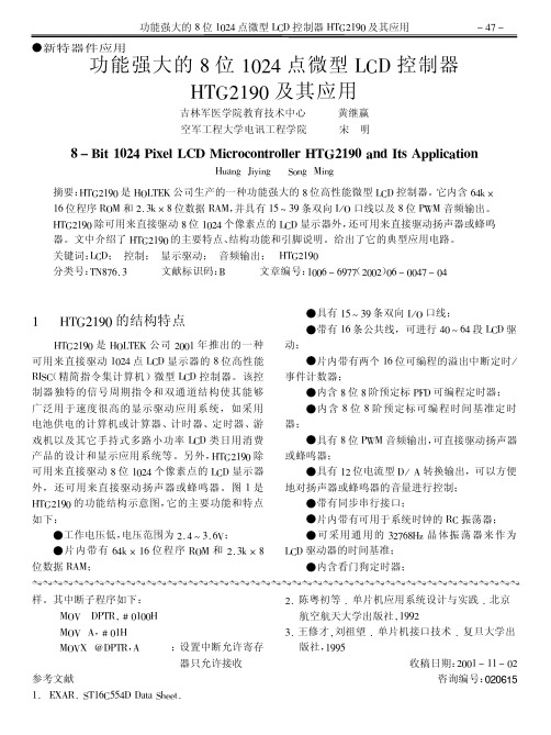
8位1024点微型LCD控制器HTG2190及其应用
! "# !
功能强大的 $ 位 %&’" 点微型 ()* 控制器 +,-’%.& 及其应用
吉林军医学院教育技术中心 空军工程大学电讯工程学院 黄继赢 宋 明
! " #$% &’() *$+,- ./0 1$234245%34--,3 678(&9’ :5; <%= >??-$2:%$45
&
典型应用
图 & ’()$*+# 的典型应用电路
$
()*$’+% 的引脚功能
()*$’+% 显示驱动控制器的引脚排列分布如图 $ 所示。各引出端与 012 板进行连接的位置坐标参 数可参考 (34)56 公司的相关资料 要功能如下: ( ,; : ’ 和 ’’" : ’’$ 脚) : 这 "% 95*% : 95*,+ 脚
7’ 8
。各引脚的主
功能强大的 * 位 ()$" 点微型 +,- 控制器 %&’$(#) 及其应用
+,-’%.& 是 +0(,:J 公司 ’&&% 年推出的一种 可用来直接驱动 %&’" 点 ()* 显示器的 $ 位高性能 (精简指令集计算机)微型 ()* 控制器。该控 3N;) 制器独特的信号周期指令和双通道结构使其能够 广泛用于速度很高的显示驱动应用系统,如采用 电池供电的计算机或计算器、计时器、定时器、游 戏机以及其它手持式多路小功率 ()* 类日用消费 产品的设计和显示应用系统等。另外, +,-’%.& 除 可用来直接驱动 $ 位 %&’" 个像素点的 ()* 显示器 外,还可用来直接驱动扬声器或蜂鸣器。图 % 是 它的主要功能和特点 +,-’%.& 的功能结构示意图, 如下: 电压范围为 ’9 " M B9 <1; !工作电压低, ! 片内带有 <"K L %< 位程序 30/ 和 ’9 BK L $ 位数据 36/;
TCC081载波芯片数据手册
I
载波通道芯片 TCC081 数据手册
载波通道芯片TCC081数据手册
1 概述 鼎信通讯有限公司根据目前国内载波抄表市场需求,结合电网特点研发出了专门应用于电力线通信
介质的载波通信系统。其核心技术利用正交码进行数据扩展频谱传输,使用电力线过零分时得到最利于 传输的3.3ms微分时段同步传输,比单纯使用扩频方式的系统通信能力和稳定性有很大提高;内置DSP 数字信号处理模块保证载波通信计算需求,使用AD采样方式进行扩频计算,其抗干扰能力大大增加。
载波通道芯片 发布
载波通道芯片 TCC081 数据手册
目录
1 概述.................................................................................................................................................................. 1 2 芯片特点.......................................................................................................................................................... 1 3 芯片方框图.................................................................................................................
八路数显报警器
1.3 试验的目的
1、了解 NE555 时基电路、CD4532 编码器电路、CD4511 译码电路、数码管显示电
路和扬声器等元件的具体应用,熟悉触摸式报警器的工作原理。
2、通过对 8 路数显报警器的组装、调试、检测,进一步掌握电子电路的装 配技巧。 3、掌握 PCB 的制作流程、焊接电路方法,加强对电路的认识和焊接的熟练。
2
第一章 设计任务与要求
1.1 设计课题
8 路数显报警器
1.2 设计要求
1、设计并安装一个 8 路数显报警器,当 8 路中某一路断开时,显示该路编 码,并发出音响。 2、显示报警编码用一位 LED 显示器显示。 3、报警存在优先级,在两个或两个以上报警条件符合时,只显示高优先级 的编码。 4、通电调试。
声报警电路由时基集成电路 NE555 和六反相器 CD4069 组成。 NE555 和 R17、 R18、C1 构成多谐振荡器,3 脚输出周期为 60S 的方波。3 脚输出低电平期间, CD4069 中的 U4A、U4B 与 R22、R25、C3 构成的低频多谐振荡器停振;3 脚输出 高电平期间,低频多谐振荡器工作。当低频振荡器输出为高电平期间由 U4E、 U4F 与 R23、R24、C4 构成的高频多谐振荡器工作,输出信号由 VT2 缓存放大 后,推动扬声器,发出类似寻呼机应答声的报警声。
R25
100k GND TH 6
R22
51k
R23 C3
1u 100k
R24
51k
C4
0.01uF
2
TR
1
555
C2
47u
C1
0.01uF
图 2.5 声报警电路图
2.2.2 总设计电路图
VDD
