华为HG630用户手册(V100R001_01,中文,HG630-10,HG630-21)
HG810用户手册
4
单击“确定”,进入Telnet运行环境。
5
输入合法的用户名和密码,即可登录HG810(HG810
预设的用户名为:root,密码为:admin)。
用以太网线连接个人计算机与HG810,若个人计算机和HG810上的网口灯都亮,则 表示网络连接成功。
2.3 FTP本地升级
HG810可以直接通过本地个人计算机自带的FTP Client进行升级。 升级文件的操作步骤如下。
介绍首次使用HG810的方法。
2.2 Telnet本地 介绍HG810用Telnet方式本地维
维护
护的方法。
2.3 FTP本地升 介绍HG810用FTP方式本地升
级
级的方法。
2.1
首次使用
HG810连接示意图如图2-1所示。 图2-1 HG810连线示意图
(1) 墙上的光 口
(4) 电话
(7) 机顶盒
目录
图1-1 HG810外观图 图1-2 HG810的组网图 图1-3 HG810前面板图 图1-4 HG810后面板图 图2-1 HG810连线示意图
插图目录
表1-1 HG810的指示灯含义 表1-2 LINK和AUTH两个指示灯的状态说明 表1-3 HG810后面板接口 表3-1 常用命令列表
表格目录
1 系统概述
关于本章
本章描述内容如下表所示。
标题
内容
1.1
产品简介 1.2 前后面板
1.1
介绍HG810的基本信息,功能和特 性。
介绍HG810的前、后面板以及指示灯 状态。
产品简介
HG810位于GPON(Gigabit-capable Passive Optical Network)用户 接入层,是面向家庭和SOHO用户设计的一款ONT设备。它应用 GPON技术,通过光纤上行接口将家庭和SOHO用户接入到Internet 网络。 HG810支持OMCI(ONT Management and Control Interface)技 术,便于服务提供商实现远程业务自动发放,以及网络维护人员 对设备进行远程维护和管理。 HG810的外观如图1-1所示。 图1-1 HG810外观图
华为USG5500_V300R001_01快速入门
• 静态IP
• DHCP • PPPoE
4
6 在“配置局域网接口”页签配置局域网参数,然后单击“下一步”。 7 在“配置局域网DHCP服务”页签,选中“启用局域网DHCP服务”,然后单击“下一步”。 8 在“核对配置信息”页签核对刚刚配置的参数,确认无误后单击“应用”。 9 配置成功后出现“快速接入向导完成”页签,单击“完成” 关闭配置向导。
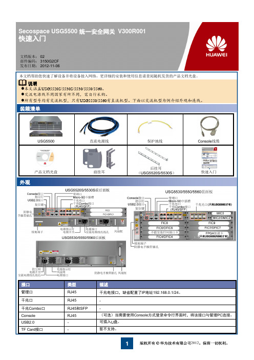
装箱清单
USG5500
产品文档光盘
外观
直流电源线 前挂耳
保护地线
Console线缆
后挂耳 (USG5520S/5530S)
快速入门
接口
管理口 千兆口 千兆Combo口 Console USB2.0 TF Card接口
类型
RJ45 RJ45 RJ45和SFP RJ45 -
描述
千兆电接口,缺省配置了IP地址192.168.0.1/24。 (可选)当需要使用Console方式登录命令行界面时,将该接口与管理PC连接。 可插入U盘。 暂不支持。
z正常时数据流向:1-2-3-4,即流量经过USG 处理后再转发。
z异常时数据流向:1-4,即流量不经过USG处 理由光Bypass卡直接透传。
设备还提供电Bypass 接口卡,这里不再介绍, 具体介绍请参见随机产品文档光盘中的《硬件 描述》。
2
出厂缺省配置
接口
GE0/0/0
管理员用户
用户名/密码
5
附录
加载License。
为了使用UTM功能和GTP功能,以及使用更多的IPSec VPN隧道数、虚拟防火墙个数和SSL并发接入用户数,需要 购买License。
HT630中文手册
3.3 用 SET 命令设置 PDT.............................................................................................................................................................11 3 DISPLAY ........................................................................................................................................................................11 第四章 系统设置状态...............................................................................................................................................................11
请勿把激光束对准自己和他人的眼球。
上海骏品电子科技有限公司
目
录
页号
HT 630.......................................................................................................................................................................................... 1 PORTABLE DATA COLLECTION....................................................................................................................................1 TERMINAL.............................................................................................................................................................................. 1 HT 630.......................................................................................................................................................................................... 1
VD2终端(HG630)配置指南
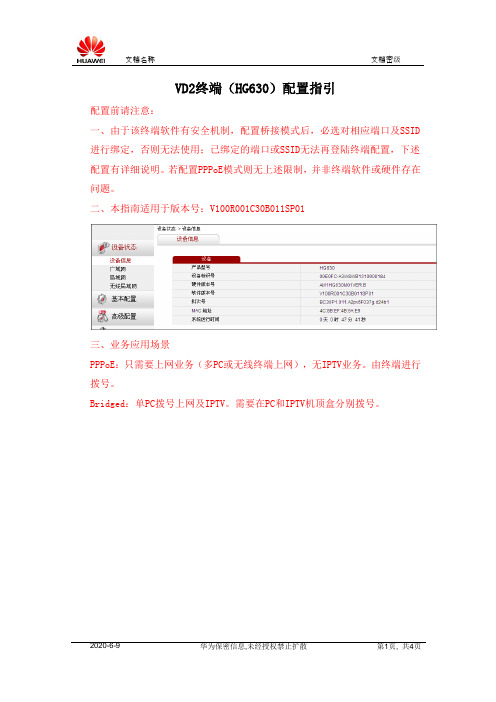
VD2终端(HG630)配置指引配置前请注意:一、由于该终端软件有安全机制,配置桥接模式后,必选对相应端口及SSID 进行绑定,否则无法使用;已绑定的端口或SSID无法再登陆终端配置,下述配置有详细说明。
若配置PPPoE模式则无上述限制,并非终端软件或硬件存在问题。
二、本指南适用于版本号:V100R001C30B011SP01三、业务应用场景PPPoE:只需要上网业务(多PC或无线终端上网),无IPTV业务。
由终端进行拨号。
Bridged:单PC拨号上网及IPTV。
需要在PC和IPTV机顶盒分别拨号。
配置方法如下:1)通过网页登录终端进行配置终端WEB配置页面的网址:http://192.168.1.1用户名/密码:admin/HuaweiAdm2)进行“基本配置”-“链路层端口”-“PTM”,点击“新建”,新建一个PTM接口。
建立一个untag的PTM接口,如下图所示的配置,然后点击“提交”保存后如下:4)进入“基本配置”-“广域网”-“WAN连接”中,点击“新建”,建立一个WAN连接,A、按下图所示进行PPPoE配置,并点击“提交”保存:链路层设备:PTM3_VID(在第3步中新建的PTM接口,请按照实际新建的名称选择)用户名和密码输入上网账号&密码。
B:按下图所示进行Bridged配置,并点击“提交”保存:链路层设备:PTM3_VID(在第3步中新建的PTM接口,请按照实际新建的名称选择)绑定列表:建议选择“LAN1”“LAN2”“LAN3”作为业务接口,务必不要勾选“LAN4”选项,将其作为调测口。
//桥接模式配置时,配置端口不能与业务端口冲突,必须保留一下端口作业务配置,不要勾选。
如下图保留LAN4口用作日常维护使用。
HUAWEI GTM900 V100R003版本说明书
HUAWEI®GTM900版本说明书V100R003华为技术有限公司版权所有,侵权必究目录1HUAWEI GTM900 V100R003 版本说明书 (3)1.1版本更新说明 (3)1.1.1GTM900V100R003C01B109SP01版本更新说明 (3)1.2历史版本更新说明 (4)1.2.1GTM900V100R003C01B108版本更新说明 (4)1.2.2GTM900V100R003C01B105版本更新说明 (4)1.2.3GTM900V100R003C01B104版本更新说明 (4)1 HUAWEI GTM900 V100R003 版本说明书本说明书描述了GTM900 V100R003版本说明。
该版本系列内嵌TCP/IP协议。
目前正式发布过的版本如下:GTM900V100R003C01B109SP01GTM900V100R003C01B108GTM900V100R003C01B105GTM900V100R003C01B1041.1 版本更新说明1.1.1 GTM900V100R003C01B109SP01版本更新说明相对上个版本GTM900V100R003C01B108,改进或解决了以下问题:需要增加一条DTMF音的AT命令AT%DTMF增加一条AT命令AT%RING用于关闭和开启来电振铃功能增加一条音频AT命令AT%CTONE音频设置参数AT%NFV AT%STN AT%SNFS AT%NFI AT%NFO AT%NFWAT%NFS AT%VLB参数越界模块开机输入PUK码后,模块不能自动搜网AT%NFV音量调节命令参数断电后无法保存,恢复为默认参数拨打110匪警电话后内容却为112电话提示激活SIM卡PIN码后再次激活时输入错误PING码后返回OK回声抑制AT命令增加抑制程度的参数ATX连接结果命令参数越界ETCPIP注册时间过长,有时超过45SAT%CGREG显示状态不正确模块建立通话后,修改模块的时间AT+CCLK,挂断电话后查询通话时间有巨大误差电话没有接通时,查询CLCC返回值不正确输入pin码后无法搜网,但强制搜网成功从SIM读出的数据不对导致不能搜网1.2 历史版本更新说明1.2.1 GTM900V100R003C01B108版本更新说明相对上个版本GTM900V100R003C01B105,改进或解决了以下问题:解决一直RING的问题解决UDP大数据交互模块复位问题。
华为 USG6305 6310S 6320 下一代防火墙产品介绍说明书
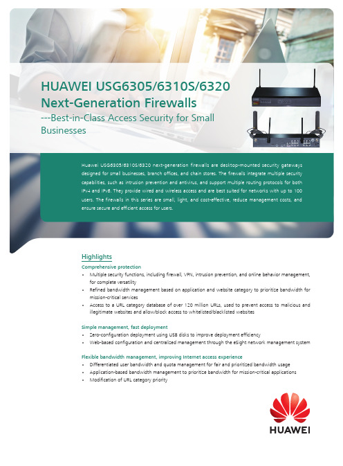
Huawei USG6305/6310S/6320 next-generation firewalls are desktop-mounted security gateways designed for small businesses, branch offices, and chain stores. The firewalls integrate multiple security capabilities, such as intrusion prevention and antivirus, and support multiple routing protocols for both IPv4 and IPv6. They provide wired and wireless access and are best suited for networks with up to 100 users. The firewalls in this series are small, light, and cost-effective, reduce management costs, and ensure secure and efficient access for users.HighlightsComprehensive protection• Multiple security functions, including firewall, VPN, intrusion prevention, and online behavior management,for complete versatility• Refined bandwidth management based on application and website category to prioritize bandwidth formission-critical services• Access to a URL category database of over 120 million URLs, used to prevent access to malicious andillegitimate websites and allow/block access to whitelisted/blacklisted websites Simple management, fast deployment• Zero-configuration deployment using USB disks to improve deployment efficiency• Web-based configuration and centralized management through the eSight network management system Flexible bandwidth management, improving Internet access experience•Differentiated user bandwidth and quota management for fair and prioritized bandwidth usage • Application-based bandwidth management to prioritize bandwidth for mission-critical applications • Modification of URL category priorityHUAWEI USG6305/6310S/6320 Next-Generation Firewalls---Best-in-Class Access Security for Small Businesses55Interfaces 1. USB Port2. Micro-SD Card Slot3. Console Port4. 4 x GE (RJ45) Ports5. 2 x Wi-Fi Antenna Jacks Interfaces 1. USB Port2. Micro-SD Card Slot3. Console Port4. 8 x GE (RJ45) Ports5. 2 x Wi-Fi Antenna JacksUSG6305-WUSG6310S-WHardwareInterfaces 1. USB Port2. Micro-SD Card Slot3. Console Port4. 4 x GE (RJ45) Ports Interfaces 1. USB Port2. Micro-SD Card Slot3. Console Port4. 8 x GE (RJ45) PortsUSG6305USG6310SDeploymentComprehensive and integrated protection for small businesses• NGFWs are deployed on egresses to provide GE and Wi-Fi interfaces in the downlink, GE interfaces in the uplink,and 3G/4G LTE backup uplinks. 4G LTE backup VPN tunnels or two LTE uplinks can be created for redundancy.• NGFWs can be deployed with the Agile Controller to form a branch access security solution that providesunified authentication of wired and wireless users and portal customization. Centralized service management eases the difficulty of managing branch offices while still allowing for platform customization for branches to perform targeted marketing.• Refined bandwidth management based on application and website category can prioritize bandwidth formission-critical services.Targeted marketing• Push of ads and questionnaires for marketing• Customization of the authentication portal page to provide marketing information or apps that arespecific to local business officesInterfaces 1. USB Port 2. SIM Card Slot3. Micro-SD Card Slot4. Console Port5. 8 x GE (RJ45) Ports6. 2 x Wi-Fi Antenna Jacks7. 2 x LTE Antenna JacksInterfaces 1. USB Port 2. Console Port3. 8 x GE (RJ45) PortsUSG6310S-WL-OVSUSG6320Software Features1: T he USG6305 and USG6310S series support log storage in SD cards. If no SD card is inserted, you can view and export system and service logs. By inserting an SD card, you can also view, export, customize, and subscribe to reports. The USG6320 supports the query and export of system and service logs but does not support report query, export, customization, or subscription.Functions marked with * are supported only in USG V500R001 and later versions.Specifications *System Performance and Capacity1. P erformance is tested under ideal conditions based on RFC 2544 and RFC 3511. The actual result may vary with deployment environments.2. Antivirus, IPS, and SA performances are measured using 100 KB of HTTP files.3. Throughput is measured with the Enterprise Traffic Model.4. SSL inspection throughput is measured with IPS-enabled and HTTPS traffic using TLS v1.2 with AES256-SHA.5. SSL VPN throughput is measured using TLS v1.2 with AES128-SHA.6. USG6000 V100R001 supports only the RESTCONF interface and cannot interwork with third-party tools.* SA indicates Service Awareness.* This content is applicable only to regions outside mainland China. Huawei reserves the right to interpret this content. Hardware Specifications1. T he following bands are supported: FDD BAND 1, 2, 3, 4, 5, 7, 8, and 20 CertificationsRegulatory, Safety, and EMC ComplianceOrdering GuideFunction LicenseAbout This PublicationThis publication is for reference only and does not constitute any commitments or guarantees. All trademarks, pictures, logos, and brands mentioned in this document are the property of Huawei Technologies Co., Ltd. or a third party.For more information, visit /en/products/enterprise-networking/security.Copyright©2018 Huawei Technologies Co., Ltd. All rights reserved.。
PM-630中文说明书
6. 技术规格................................ 24
7. 保养和支持.............................. 25
7.1 保养.............................................. 25 7.2 支持理念.......................................... 25 7.3 标准保修和延期保修................................ 25 7.4 废物处置.......................................... 25
2.3 测量范围
测量范围取决于钢筋尺寸。下图指明了预期的保护层测量精度。它符合 BS1881 第 204 部分,适合有足够间距的单条钢筋。
混凝土
磁场
钢筋
图 1: 测量原则
Profometer PM-600/630 采用不同的线圈布局,以生成多个磁场。高级信 号处理可查找钢筋,并测量保护层和钢筋直径。 此方法不受所有非导电材料影响,比如,混凝土、木头、塑料和砖块等。 然而,磁场内任何类型的导电材料(半径大约为 200 mm / 8” 的圆周范 围)均可能影响测量结果。
电,或在仪器外部给电池充电。在这种情况下充满需要耗时 < 4h。) 将通用探头 (C) 连接至 Profometer 触摸屏装 置 (A) 上侧的其中一个接口。
3. 使用..................................... 8
3.1 入门指南........................................... 8 3.2 主菜单............................................. 9 3.3 设置............................................... 9 3.4 测量屏幕.......................................... 10 3.5 测量模式.......................................... 11 3.6 数据处理.......................................... 16 3.7 实用提示.......................................... 20
HUAWEI_TE30_会议电视终端_V100R001C02SPC100_版本说明书
华为技术有限公司
地址: 网址:
深圳市龙 岗区坂 田华为 总部办 公楼
邮编:518129
文档版本 01 (2014-08-11)
华为专有 和保密 信息
版权所有 © 华为技术有限公司
i
HUAW EI TE30 会议电视终端 版本说明 书
目录
目录
1 版本配套说明.................................................................................................................................. 1
1.1 产品版本信息 .................................................................................................................................................................................1 1.2 产品版本演进关系 ........................................................................................................................................................................2 1.3 软件版本配套说明 ........................................................................................................................................................................2 1.4 硬件版本配套说明 ........................................................................................................................................................................2 1.5 相关产品版本配套说明 ...............................................................................................................................................................3 1.6 软件文件清单 .................................................................................................................................................................................4 1.6.1 用户升级文件..............................................................................................................................................................................4 1.7 防病毒扫描结果 ............................................................................................................................................................................5
华为太阳能发电器快速引导说明书
SUN2000-(20KTL-M3, 33KTL-NH, 40KTL-NH) Quick GuideIssue: 06Part Number: 31500HLNDate: 2023-01-10HUAWEI TECHNOLOGIES CO., LTD.•The information in this document is subject to change without notice. Every effort has been made in the preparation of this document to ensure accuracy of the contents, but allstatements, information, and recommendations in this document do not constitute a warranty of any kind, express or implied.•Only qualified and trained electrical technicians are allowed to operate the device. Operation personnel should understand the composition and working principles of the grid-tied PV power system and local regulations.•Before installing the device, read the user manual carefully to get familiar with product information and safety precautions. Huawei shall not be liable for any consequences caused by the violation of the storage, transportation, installation, and operation regulations specified in this document and the user manual.•Use insulated tools when installing the device. For personal safety, wear proper personal protective equipment (PPE).1Overview(1) LED indicators(2) Host panel(3) Heat sink(4) Screw holes for fixing the awning(5) Communications port (COM)(6) Hole for the DC switch locking screw(7) DC switch(8) Smart Dongle port a(9) Ventilation valves(10) DC input terminals (PV1–PV8)(11) AC output port(12) Spot-check terminal connection box(13) Ground pointNote a: The SUN2000MA V100R001C20SPC109 and later versions support the Smart Dongle networking only in the sub-50 kW scenario, and do not support power control at the grid-connection point.2Installation RequirementsAngle SpaceDimensions3Installing a Solar Inverter•M12x40 bolt assemblies are supplied with the solar inverter. If the bolt length does not meet the installation requirements, prepare M12 bolt assemblies by yourself and use themtogether with the supplied M12 nuts.•This quick guide describes how to install a solar inverter on a support. For details about wall-mounted installation, see the user manual.•Before installing the mounting bracket, remove the security Torx wrench and set it aside.Position for bindingthe security Torxwrench1.Install the mounting bracket.Moving the Solar Inverter It is recommended that anti-rust measures be taken on the positions for drilling holes.2.Install the solar inverter onto themounting bracket.3.Tighten the security Torx screws on bothsides.Secure the screws on the sides before connecting cables.Preparations4.14Connecting Cables•To ensure that the inverter can be safely disconnected from the power grid when anexception occurs, connect an AC switch to the AC side of the inverter. Select an appropriate AC switch in accordance with local industry standards and regulations.•The cable specifications must comply with local standards.Connect cables in accordance with local installation laws and regulations.•Before connecting cables, ensure that the DC switch of the solar inverter and all the switches connected to it are set to OFF. Otherwise, the high voltage produced by the solar inverter may cause electric shocks.No.CableTypeSpecifications1PE cable Single-core outdoor copper-core cableConductor cross-sectional area ≥ 5.5 mm 22AC output power cable Outdoor copper-core/aluminum-core cable•Conductor cross-sectional area: 16-50 mm 2outdoor copper-core cable or 35-50 mm 2outdoor aluminum-core cable •Cable outer diameter: 16–38 mm 3DC input power cableCommon outdoor PV cable in the industry (recommendedmodel: PV1-F)•Conductor cross-sectional area: 3.5–6 mm 2•Cable outer diameter: 5.5–9 mm 4(Optional)RS485 communications cable Two-core outdoor shielded twisted pair •Conductor cross-sectional area: 0.2–1 mm 2•Cable outer diameter: 4–11 mm5AC circuit breakerRecommended: three-phase AC circuit breakerRated voltage ≥ 500 V AC Rated current: 80 A•Do not connect loads between the inverter and the AC switch that directly connects to the inverter. Otherwise, the switch may trip by mistake.•If an AC switch is used with specifications beyond local standards, regulations, or Huawei's recommendations, the switch may fail to turn off in a timely manner in case of exceptions, causing serious faults.Each inverter must be equipped with an AC output switch. Multiple inverters cannot connect to the same AC output switch.Connecting a PE Cable4.2•The PE point at the AC output port is used only as a PE equipotential point, not a substitute for the PE point on the enclosure.•It is recommended that silica gel or paint be applied around the ground terminal after the PE cable is connected.Do not connect the neutral wire to the enclosure as a PE cable. Otherwise, electric shocks may occur.Reserved PE pointInstalling the AC Output Power Cable4.3•Use a socket wrench and extension rod to connect the AC power cable. The extension rod must be longer than 100 mm.•Do not install third-party devices in the AC connection box.•You need to prepare M8 OT terminals by yourself.1.Remove the AC terminal box and install partition boards.2.Connect the AC output power cable (using a four-core cable as an example).•To avoid damaging the rubber liner, do not route a cable with a crimped OT terminal directly through it.•The cable colors in figures are for reference only. Select appropriate cables according to the local standards.Installing DC Input Power Cablese the positive and negative Amphenol Helios H4 metal terminals and DC connectors supplied with the solar inverter. Using incompatible positive and negative metal terminals and DC connectors may result in serious consequences. The caused device damage is not covered under any warranty.2.For models of the crimping tool and removal wrench, use the recommended model or contact your Amphenol dealer.3.Ensure that the PV module output is well insulated to ground.4.The DC input voltage of the SUN2000-20KTL-M3 shall not exceed 750V DC under any circumstance.5.The DC input voltage of the SUN2000-33KTL/40KTL-NH shall not exceed 1100 V DC under any circumstance.6.Before installing DC input power cables, label the cable polarities to ensure correct cable connections.7.If a DC input power cable is reversely connected and the DC switch is turned on, do not operate on the DC switch or the positive/negative connectors immediately. Otherwise, the device may be damaged. The caused device damage is not covered under any warranty. Wait until the night when solar irradiance declines and the PV string current drops to below 0.5 A. Then set the DC switch to the OFF position, remove the positive and negative connectors, and correct the polarity of the DC input power cable.1.Connect the DC power cables.Positive connectorNegative connectorPositive metal terminalNegative metal terminalEnsure that the cable cannot be pulled out after being crimped.ClickClickEnsure that cables are connected correctly.Use the wrench shown in the figure to tighten the locking nut. When the wrench slips during the tightening, the locking nut has beentightened.H4TC0003(Amphenol)H4TW0001(Amphenol)4.5(Optional) Installing the Smart Dongle•The Smart Dongle is not provided in standard configuration.•If your Smart Dongle is not equipped with a SIM card, prepare a standard SIM card (size: 25 mm x 15 mm) with the capacity greater than or equal to 64 KB.•When installing the SIM card, determine its installation direction based on the silk screen and arrow on the card slot.•Press the SIM card in place to lock it, indicating that the SIM card is correctly installed.•When removing the SIM card, push it inwards to eject it.•For details about how to operate the 4G Smart Dongle SDongleA-03, see SDongleA-03 Quick Guide (4G).•The quick guide is delivered with the Smart Dongle or can be obtained by scanning the QR codes.Smart Dongle port (4G/WLAN-FE)Quick GuideWhen reinstalling the cover of the Smart Dongle,ensure that the buckle springs back in place.Installing the Signal Cable4.6•When laying out the signal cable, separate it from the power cable and keep it away from strong interference sources to avoid strong communication interference.•Ensure that the protective layer of the cable is inside the connector, that excess core wires are cut off from the protection layer, that the exposed core wire is totally inserted into the cable hole, and that the cable is connected securely.COM Port Pin DefinitionsNo.Definition Function Description No.Definition Function Description1485A1-1RS485differentialsignal +Used to cascadeinverters orconnect to theSmartLogger.2485A1-2RS485differentialsignal +Used tocascadeinverters orconnect to theSmartLogger.3485B1-1RS485differentialsignal –4485B1-2RS485differentialsignal –5PE Groundpoint on theshield layer–6PEGround pointon the shieldlayer–7485A2RS485differentialsignal +Reserved.Connects to theRS485 signalport on thepower gridschedulingpower meter.8DIN1Reserved–9485B2RS485differentialsignal –10DIN211–––12DIN3 13GND GND–14DIN4 15DIN5Reserved–16GNDScenarios Where No Signal Cable Is ConnectedIf no signal cable is required for the SUN2000, use waterproof plugs to block the wiring holes on the signal cable connector and connect the signal cable connector to the communications port on the SUN2000 to improve the waterproof performance of the SUN2000.Scenarios Where Signal Cable Is Connected1.Connect the signal cable to the signal connector.If two or more solar inverters are cascaded, install the RS485 communications cable.2.Connect the signal cable connector to the communications port.Communicationsport (COM)5Verifying the InstallationNo.Acceptance Criteria1The solar inverter is installed correctly and securely.2The cables are routed properly as required by the customer.3Cable ties are evenly distributed and no burr exists.4The PE cable is connected correctly and securely.5The DC switch and all the switches connected to the solar inverter are set to the OFF position.6The AC output power cable, DC input power cables, and signal cable are connected correctly and securely.7Unused terminals and ports are locked by watertight caps.8The installation space is proper, and the installation environment is clean and tidy.6System Power-OnBefore turning on the AC switch between the solar inverter and the power grid, check that the AC voltage is within the specified range using a multimeter set to the AC position.1.Turn on the AC switch between the solar inverter and the power grid.2.Turn on the DC switch at the bottom of the solar inverter.3.Observe the LED indicators to check the operating status of the solar inverter.Category Status(Blinking Slowly: On for 1s and thenOff for 1s; Blinking Fast: On for 0.2s and thenOff for 0.2s)DescriptionRunning indicator LED1LED2–Steady green Steady green The solar inverter is operating in grid-tied mode.Blinking green slowly Off The DC is on and the AC is off. Blinking green slowly Blinking green slowlyBoth the DC and AC are on, and thesolar inverter is not supplying powerto the power grid.Off Blinking green slowly The DC is off and the AC is on.Off Off Both the DC and AC are off. Blinking red fast–DC environment alarm–Blinking red fast AC environment alarmSteady red Steady red FaultCommunic ations indicator LED3–Blinking green fast Communication is in progress. Blinking green slowly Mobile phone accessOff No communicationNote: If LED1, LED2, and LED3 are steady red, the solar inverter is faulty and needs to be replaced.7System Commissioning (FusionSolar APP)•Install the FusionSolar app (5.7.001 or later).•The screenshots in this document correspond to app version should be 5.7.001.The installer can be registered using a mobile number (only in China) or an email address. The two registration modes areautomatically switched based on the server settings.Run the FusionSolar app. If no account and password are created, tap No account , select I'm an installer , and enter the registration information.Downloading the App(Optional) Registering an Installer Account•Method 2: Search for FusionSolar on Huawei AppGallery and download the latest installation package.•Method 1: Access https:// using the mobile phone browser and download the latest installation package.FusionSolar•Method 3: Scan the following QR code and download the latest installation package.Creating a PV Plant and a UserFor details about how to usethe site deployment wizard, seeFusionSolar App Quick Guide.During the FusionSolar appupgrade, scan the QR code todownload the quick guide.1.Access Device commissioning.Scenario 1: Your phone is not connected to the Internet.Scenario 2: Your phone is connected to the Internet.When your phone is connected to the Internet, Device commissioning is not displayed after youtap ....Device Commissioning8System Commissioning (SmartLogger Web)8.11.The operating system of Windows 7 or later is supported.2.The WebUI snapshots are for reference only, and the actual display prevails.Preparations and WebUI Login1.Connect the network cable between the network port on the PC and the SmartLogger.2.Set the IP addresses of the PC and SmartLogger in the same network segment.Port IP Settings SmartLogger Default Value PC Setting Example LAN portIP address 192.168.8.10192.168.8.11Subnet mask 255.255.255.0255.255.255.0Default gateway 192.168.8.1192.168.8.1WAN portIP address192.168.0.10192.168.0.11Subnet mask 255.255.255.0255.255.255.0Default gateway192.168.0.1192.168.0.12.Connect to the solar inverter WLAN and log in as installer to access the device commissioning screen.When the IP address of the WAN port is on the 192.168.8.1–192.168.8.255 network segment, the IP address of the LAN port is automatically switched to 192.168.3.10, and the defaultgateway is 192.168.3.1. If the connection port is a LAN port, adjust the network configuration of the PC accordingly.8.2Parameter DescriptionLanguage Set this parameter as required.User name Select admin.Password •The initial password isChangeme. Use the initialpassword upon first power onand change it immediately after login. To ensure accountsecurity, change the passwordperiodically and keep the newpassword in mind. Not changing the initial password may causepassword disclosure. Apassword left unchanged for along period of time may bestolen or cracked. If a passwordis lost, devices cannot beaccessed. In these cases, theuser is liable for any loss caused to the PV plant.•If you enter wrong passwords for five consecutive times within5 minutes, your account will belocked out. Try again 10minutes later.3.Set LAN parameters.•If the SmartLogger is connected to alocal area network (LAN) and a proxyserver has been set, you need to cancelthe proxy server settings.•If the SmartLogger is connected to theInternet and the PC is connected to theLAN, do not cancel the proxy serversettings.a.Open Internet Explorer.b.Choose Tools> Internet Options.c.Click the Connections tab and then clickLAN settings.d.Clear Use a proxy server for your LAN.e.Click OK.Commissioning Through Deployment Wizard1.Enter https://XX.XX.XX.XX in the addressbox of the browser (XX.XX.XX.XX is thedefault IP address of the SmartLogger). Ifyou log in to the WebUI for the first time,a security risk warning is displayed. ClickContinue to this website.2.Select an User Name to log in.9FAQ: How Do I Reset the Password?1.Check that the AC and DC power supplies to the solar inverter are connected simultaneously, and that the and indicators are steady green or blink slowly for more than 3 minutes.2.Turn off the AC switch, set the DC switch at the bottom of the solar inverter to OFF, and wait until all indicators on the solar inverter panel turn off.plete the following operations within 3 minutes:a.Turn on the AC switch and wait until the indicator blinks.b.Turn off the AC switch and wait until all indicators on the solar inverter panel turn off.c.Turn on the AC switch and wait until all LED indicators on the inverter panel blink and turn off after about 30s.a.Wait until the indicator blinks.b.Obtain the initial WLAN hotspot name (SSID) and initial password (PSW) from the label on the side of the solar inverter to connect to the app.c.On the login page, set a new login password and log in to the app.You are advised to reset the password in the morning or at night when the solar irradiance is low.4.Wait until the three indicators on the inverter panel blink green quickly and then blink red quickly, indicating that the password has been restored.5.Reset the password within 10 minutes. (If no operation is performed within 10 minutes, all parameters of the solar inverter remain the same as those before the reset.)3.Click Deployment Wizard and set parameters as prompted.Click Skip for unused devices.Huawei Technologies Co., Ltd. Huawei Industrial Base, Bantian, Longgang Shenzhen 518129 People's Republic of China。
华为设备用户手册说明书

Copyright © Huawei Technologies Co., Ltd. 2013. All rights reserved.No part of this manual may be reproduced or transmitted in any form or by any means without prior written consent of Huawei Technologies Co., Ltd. and its affiliates ("Huawei").The product described in this manual may include copyrighted software of Huawei and possible licensors. Customers shall not in any manner reproduce, distribute, modify, decompile, disassemble, decrypt, extract, reverse engineer, lease, assign, or sublicense the said software, unless such restrictions are prohibited by applicable laws or such actions are approved by respective copyright holders. Trademarks and Permissions , , and are trademarks or registered trademarks of Huawei Technologies Co., Ltd.Other trademarks, product, service and company names mentioned may be the property of their respective owners.NoticeSome features of the product and its accessories described herein rely on the software installed, capacities and settings of local network, and therefore may not be activated or may be limited by local network operators or network service providers.Thus, the descriptions herein may not exactly match the product or its accessories which you purchase.Huawei reserves the right to change or modify any information or specifications contained in this manual without prior notice and without any liability.DISCLAIMERALL CONTENTS OF THIS MANUAL ARE PROVIDED “AS IS”. EXCEPT AS REQUIRED BY APPLICABLE LAWS, NO WARRANTIES OF ANY KIND, EITHER EXPRESS OR IMPLIED, INCLUDING BUT NOT LIMITED TO, THE IMPLIED WARRANTIES OF MERCHANTABILITY AND FITNESS FOR A PARTICULAR PURPOSE, ARE MADE IN RELATION TO THE ACCURACY , RELIABILITY OR CONTENTS OF THIS MANUAL.TO THE MAXIMUM EXTENT PERMITTED BY APPLICABLE LAW, IN NO EVENT SHALL HUAWEI BE LIABLE FOR ANY SPECIAL, INCIDENTAL, INDIRECT, OR CONSEQUENTIAL DAMAGES, OR LOSS OF PROFITS, BUSINESS, REVENUE, DATA, GOODWILL SAVINGS OR ANTICIPATED SAVINGS REGARDLESS OF WHETHER SUCH LOSSES ARE FORSEEABLE OR NOT .THE MAXIMUM LIABILITY (THIS LIMITATION SHALL NOT APPLY TO LIABILITY FOR PERSONAL INJURY TO THE EXTENT APPLICABLE LAW PROHIBITSSUCH A LIMITATION) OF HUAWEI ARISING FROM THE USE OF THE PRODUCT DESCRIBED IN THIS MANUAL SHALL BE LIMITED TO THE AMOUNT PAID BY CUSTOMERS FOR THE PURCHASE OF THIS PRODUCT.Import and Export RegulationsCustomers shall comply with all applicable export or import laws and regulations and be responsible to obtain all necessary governmental permits and licenses in order to export, re-export or import the product mentioned in this manual including the software and technical data therein.Privacy PolicyTo better understand how we protect your personal information, please see the privacy policy at /en/privacy-policy/index.htm. Safety informationThis section contains important information about the operation of your device. It also contains information about how to use the device safely. Read this information carefully before using your device.Electronic deviceDo not use your device if using the device is prohibited. Do not use the device if doing so causes danger or interference with other electronic devices. Interference with medical equipment●Follow rules and regulations set forth by hospitals and health care facilities. Do not use your device where prohibited. ●Some wireless devices may affect the performance of hearing aids or pacemakers. Consult your service provider for more information. ● Pacemaker manufacturers recommend that a minimum distance of 15 cm be maintained between a device and a pacemaker to prevent potential interference with the pacemaker. If using a pacemaker, hold the device on the side opposite the pacemaker and do not carry the device in your front pocket.Areas with flammables and explosives ● Do not use the device where flammables or explosives are stored (in a gas station, oil depot, or chemical plant, for example). Using your device in these environments increases the risk of explosion or fire. In addition, follow the instructions indicated in text or symbols.● Do not store or transport the device in containers with flammable liquids, gases, or explosives.Traffic security ● Observe local laws and regulations while using the device. To reduce the risk of accidents, do not use your wireless device while driving.● Concentrate on driving. Your first responsibility is to drive safely.● RF signals may affect the electronic systems of motor vehicles. For more information, consult the vehicle manufacturer.● Do not place the device over the air bag or in the air bag deployment area in a motor vehicle. Doing so may hurt you because of the strong force when the air bag inflates.● Do not use your device while flying in an aircraft or immediately before boarding. Using wireless devices in an aircraft may disrupt wireless networks, present a hazard to aircraft operation, or be illegal.Operating environment ● Avoid dusty, damp, or dirty environments. Avoid magnetic fields. Using the device in these environments may result in circuit malfunctions.● Do not use your device during thunderstorms to protect your device against any danger caused by lightning.● Ideal operating temperatures are 0 to ℃+35. Ideal storage temperatures are ℃-10 to ℃+45. Extreme heat or cold may damage your device or accessories.℃ ● Keep the device and accessories in a well-ventilated and cool area away from direct sunlight. Do not enclose or cover your device with towels or other objects. Do not place the device in a container with poor heat dissipation, such as a box or bag.● Do not expose your device to direct sunlight (such as on a car dashboard) for prolonged periods.● To protect your device or accessories from fire or electrical shock hazards, avoid rain and moisture.● Keep the device away from sources of heat and fire, such as a heater, microwave oven, stove, water heater, radiator, or candle.● Stop using your device or applications for a while if the device is overheated. If skin is exposed to an overheated device for an extended period, low temperature burn symptoms, such as red spots and darker pigmentation, may occur. ● Do not touch the device's antenna. Otherwise, communication quality may be reduced.● Do not allow children or pets to bite or suck the device or accessories. Doing so may result in damage or explosion.● Observe local laws and regulations, and respect the privacy and legal rights of others.Child's safety ●Comply with all precautions with regard to child's safety. Letting children play with the device or its accessories may be dangerous. The device includes detachable parts that may present a choking hazard. Keep away from children.●The device and its accessories are not intended for use by children. Childrenshould only use the device with adult supervision.Accessories●Using an unapproved or incompatible power adapter, charger or battery maycause fire, explosion or other hazards.●Choose only accessories approved for use with this model by the devicemanufacturer. The use of any other types of accessories may void the warranty, may violate local regulations and laws, and may be dangerous. Please contact your retailer for information about the availability of approved accessories in your area.Charger safety●For pluggable devices, the socket-outlet shall be installed near the devices andshall be easily accessible.●Unplug the charger from electrical outlets and the device when not in use.●Do not drop or cause an impact to the charger.●If the power cable is damaged (for example, the cord is exposed or broken), orthe plug loosens, stop using it at once. Continued use may lead to electric shocks, short circuits, or fire.●Do not touch the power cord with wet hands or pull the power cord to disconnectthe charger.●Do not touch the device or the charger with wet hands. Doing so may lead toshort circuits, malfunctions, or electric shocks.●If your charger has been exposed to water, other liquids, or excessive moisture,take it to an authorized service center for inspection.●Ensure that the charger meets the requirements of Clause 2.5 inIEC60950-1/EN60950-1 and has been tested and approved according tonational or local standards.●Connect the device only to products with the USB-IF logo or with USB-IFcompliance program completion.Battery safety●Do not connect battery poles with conductors, such as keys, jewelry, or othermetal materials. Doing so may short-circuit the battery and cause injuries or burns.●Keep the battery away from excessive heat and direct sunlight. Do not place it onor in heating devices, such as microwave ovens, stoves, or radiators. Batteries may explode if overheated.●Do not attempt to modify or remanufacture the battery, insert foreign objects intoit, or immerse or expose it to water or other liquids. Doing so may lead to fire, explosion, or other hazards.●If the battery leaks, ensure that the electrolyte does not make direct contact withyour skins or eyes. If the electrolyte touches your skins or splashes into your eyes, immediately flush with clean water and consult a doctor.●In case of battery deformation, color change, or overheating while charging orstoring, immediately stop using the device and remove the battery. Continued use may lead to battery leakage, fire, or explosion.●Do not put batteries in fire as they may explode. Damaged batteries may alsoexplode.●Dispose of used batteries in accordance with local regulations. Improper batteryuse may lead to fire, explosion, or other hazards.●Do not allow children or pets to bite or suck the battery. Doing so may result indamage or explosion.●Do not smash or pierce the battery, or expose it to high external pressure. Doingso may lead to a short circuit or overheating.●Do not drop the device or battery. If the device or battery is dropped, especiallyon a hard surface, and may be damaged.●If the device standby time shortens significantly, replace the battery.●When the device has a built-in, non-removable battery, do not attempt to removethe battery, otherwise the device may be damaged. To replace the battery, take the device to an authorized service center.Cleaning and maintenance●Keep the device and accessories dry. Do not attempt to dry it with an externalheat source, such as a microwave oven or hair dryer.●Do not expose your device or accessories to extreme heat or cold. Theseenvironments may interfere with proper function and may lead to fire orexplosion.●Avoid collision, which may lead to device malfunctions, overheating, fire, orexplosion.●Before you clean or maintain the device, stop using it, stop all applications, anddisconnect all cables connected to it.●Do not use any chemical detergent, powder, or other chemical agents (such asalcohol and benzene) to clean the device or accessories. These substances may cause damage to parts or present a fire hazard. Use a clean, soft, and dry cloth to clean the device and accessories.●Do not place magnetic stripe cards, such as credit cards and phone cards, nearthe device for extended periods of time. Otherwise the magnetic stripe cards may be damaged.●Do not dismantle or remanufacture the device and its accessories. This voids thewarranty and releases the manufacturer from liability for damage. In case of damage, contact an authorized service center for assistance or repair.Disposal and recycling informationThis symbol (with or without a solid bar) on the device, batteries (if included), and/or the packaging, indicates that the device and its electrical accessories (for example, a headset, adapter, or cable) and batteries should not be disposed of as household garbage. These items should not be disposed of as unsorted municipal waste and should be taken to a certified collection point for recycling or proper disposal.For more detailed information about device or battery recycling, contact your local city office, household waste disposal service, or retail store.Disposal of the device and batteries (if included) is subject to WEEE Directive Recast (Directive 2012/19/EU) and Battery Directive (Directive 2006/66/EC). The purpose of separating WEEE and batteries from other waste is to minimize the potential environmental impacts and human health risk of any hazardous substances that may be present.Reduction of hazardous substancesThis device is compliant with the REACH Regulation [Regulation (EC) No1907/2006] and RoHS Directive Recast (Directive 2011/65/EU). Batteries (if included) are compliant with the Battery Directive (Directive 2006/66/EC). Forup-to-date information about REACH and RoHS compliance, please visit the web site /certification.EU regulatory conformanceRF exposure requirementsImportant safety information regarding radio frequency (RF) radiation exposure:RF exposure guidelines require that the device be used at a minimum of 1.5 cm from the human body. Failure to observe this guideline may result in RF exposure exceeding limits.Certification information (SAR)This device meets guidelines for exposure to radio waves.Your device is a low-power radio transmitter and receiver. As recommended by international guidelines, the device is designed not to exceed the limits for exposure to radio waves. These guidelines were developed by the International Commission on Non-Ionizing Radiation Protection (ICNIRP), an independent scientific organization, and include safety measures designed to ensure the safety of all users, regardless of age and health.The Specific Absorption Rate (SAR) is the unit of measurement for the amount of radio frequency energy absorbed by the body when using a device. The SAR value is determined at the highest certified power level in laboratory conditions, but the actual SAR level during operation can be well below the value. This is because the device is designed to use the minimum power required to reach the network.The SAR limit adopted by Europe is 2.0 W/kg averaged over 10 grams of tissue, and the highest SAR value for this device complies with this limit.StatementHereby, Huawei Technologies Co., Ltd. declares that this device is in compliance with the essential requirements and other relevant provisions of Directive1999/5/EC.For the declaration of conformity, visit the web site/certification.The following marking is included in the product:0682This device may be operated in all member states of the EU.Observe national and local regulations where the device is used.This device may be restricted for use, depending on the local network. Restrictions in the 2.4 GHz band:Norway: This subsection does not apply for the geographical area within a radius of 20 km from the centre of Ny-Ålesund.Please visit /worldwide/support/hotline for recently updated hotline and email address in your country or region.Version: V100R001_03 Part Number: 31222350。
HUAWEI TE30 会议电视终端 V100R001C10 用户指南 01
HUAWEI TE30 会议电视终端V100R001C10用户指南文档版本01发布日期2014-12-23版权所有 © 华为技术有限公司 2014。
保留一切权利。
非经本公司书面许可,任何单位和个人不得擅自摘抄、复制本文档内容的部分或全部,并不得以任何形式传播。
商标声明和其他华为商标均为华为技术有限公司的商标。
本文档提及的其他所有商标或注册商标,由各自的所有人拥有。
注意您购买的产品、服务或特性等应受华为公司商业合同和条款的约束,本文档中描述的全部或部分产品、服务或特性可能不在您的购买或使用范围之内。
除非合同另有约定,华为公司对本文档内容不做任何明示或默示的声明或保证。
由于产品版本升级或其他原因,本文档内容会不定期进行更新。
除非另有约定,本文档仅作为使用指导,本文档中的所有陈述、信息和建议不构成任何明示或暗示的担保。
华为技术有限公司地址:深圳市龙岗区坂田华为总部办公楼邮编:518129网址:前言概述本指南介绍HUAWEI TE30 会议电视终端(以下统一简称终端)的产品特性,通过遥控器操作界面召开会议、接听呼叫、进行会议控制等日常使用方法。
如果您需要获取本产品配套的其他资料,请登录网站,进入“服务支持 > 产品支持 > 统一通信与协作 > 智真和视讯 > 智真终端 > 群组终端 >TE30”获取。
读者对象本指南适用但不限于以下类别用户阅读:l遥控器操作界面普通用户:除系统配置外,可以对遥控器的操作界面的呼叫、会议控制等进行操作。
l遥控器操作界面管理员用户:可以对Web界面和遥控器操作界面所有菜单进行操作。
符号约定在本文中可能出现下列标志,它们所代表的含义如下。
修订记录修改记录累积了每次文档更新的说明。
最新版本的文档包含以前所有文档版本的更新内容。
文档版本 01 (2014-12-23)第一次发布。
目录前言 (ii)1 概述 (1)2 了解用户界面 (3)2.1 了解触摸屏界面 (4)2.2 了解Web界面 (5)2.3 了解遥控器操作界面 (6)3 了解遥控器 (9)4 开启终端 (11)5 召开会议 (13)5.1 召开两方会议 (14)5.2 召集多方会议 (14)6 加入会议 (17)7 语音呼叫 (18)8 共享会议材料 (20)9 调节本地会场音量 (21)10 关闭或打开本地麦克风 (22)11 调节摄像机 (23)11.1 调节焦距 (24)11.2 转动摄像机镜头方位 (24)11.3 保存预置位 (25)12 切换屏幕布局 (27)13 会议控制 (29)14 呼叫保持 (34)15 开启免打扰 (37)16 暂隐图像 (38)17 结束或退出会议 (39)A 术语 (40)1概述HUAWEI TE30 会议电视终端是一款高性能高清视频会议终端,提供超带宽音频,最高支持1080p30分辨率,支持Wi-Fi接入,对表情、语调、肢体动作、眼神都可以进行捕捉和传达,使与会者仿佛在进行面对面会议。
S2300&S3300 V100R006C03 版本说明书
主机软件
无
BootROM 主系 S2300EI-bootrom.bin
无
统软件
Web 网管软件 S2300EI-V100R006C03.001.web.zi 无 p
文档版本 01 (2012-06-30)
华为专有和保密信息
1
1
版权所有 © 华为技术有限公司
目录
目录
1 版本配套说明.................................................................................................................................. 1
1.1 产品版本信息................................................................................................................................................. 1 1.2 软件版本配套说明 ......................................................................................................................................... 1 1.3 单板版本配套说明 ......................................................................................................................................... 3
Secoway USG2100&2200&5100 V300R001 快速入门 07
USG5120
• 2U高度硬件平台,USG5120支持交流电源和直流电源两种机型。 • 当在FIC5和FIC6槽位的下半部分安装FIC接口卡时,为了防尘需要在DFIC槽位的上半部分安装一个假面板,以封闭后面板。
SYS ACT (绿色)
FLASH CARD
WiFi (仅USG2100)
说明
常亮:电源已上电。 熄灭:电源不在位或未上电。
每2秒闪1次(0.5Hz):系统正常运行。 每秒闪2次(2Hz)或常亮:系统正在启动中。 每秒闪8次(8Hz):系统在升级系统软件或配 置文件。 熄灭:系统有故障或未上电。
常亮:Flash接口工作正常。 熄灭:Flash接口故障或没有连接。
USG5150 USG5160
FIC7
-
FIC8
-
MIC1/MIC2 Y
MIC3/MIC4 Y
FIC5/FIC6/ FIC7/FIC8
FIC9
-
FIC10
-
Y
-
-
-
-
Y
只能插在槽
位下部
-
Y
-
Y
Y
-
-
-
-
Y
只能插在槽
位下部
-
-
-
-
2E1/4E1/8E1、
2CE1/4CE1/8C E1、2FE+2FE Combo、E4BY
DFIC
16GE+4SFP、 18FE+2SFP
-
-
HG630开路由步骤简要说明
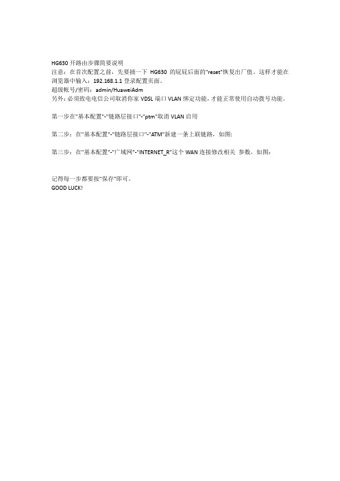
HG630开路由步骤简要说明
注意:在首次配置之前,先要捅一下HG630的屁屁后面的"reset"恢复出厂值。
这样才能在浏览器中输入:192.168.1.1登录配置页面。
超级帐号/密码:admin/HuaweiAdm
另外:必须致电电信公司取消你家VDSL端口VLAN绑定功能,才能正常使用自动拨号功能。
第一步在"基本配置"-"链路层接口"-"ptm"取消VLAN启用
第二步:在"基本配置"-"链路层接口"-"ATM"新建一条上联链路,如图:
第三步:在"基本配置"-"广域网"-"INTERNET_R"这个WAN连接修改相关参数,如图:
记得每一步都要按"保存"即可。
GOOD LUCK!。
华为PON产品手册V1[1].1
![华为PON产品手册V1[1].1](https://img.taocdn.com/s3/m/207594fc58fb770bf68a5516.png)
华为PON产品手册华为PON产品由OLT和ONU两大部分构成,主要的产品型号列表如下:目录1OLT产品系列 (2)1.1MA5680T (2)1.2MA5683T (4)2ONU产品系列 (6)2.1HG810e (6)2.2HG813e (7)2.3HG850e (7)2.4HG866e (8)2.5HG8240 (9)2.6HG8245 (9)2.7HG810 (10)2.8HG813 (10)2.9HG850a (11)2.10HG861 (11)2.11HG863 (12)2.12HG866 (13)2.13HG8500 (13)2.14MA5610 (14)2.15MA5612 (16)2.16MA5620/MA5626 (18)2.17MA5616 (20)2.18MA5603T (22)2.19UA5000 (24)1OLT产品系列1.1MA5680TMA5680T光接入设备作为GPON/EPON系统中OLT设备,和终端ONU设备配合使用,可以提供GPON/EPON接入业务,满足FTTH光纤到户、FTTB光纤到楼、微基站传输、IP专线互联、带宽批发等组网需求。
硬件外观MA5680T业务框有23个槽位,顶部配置一个风扇框。
业务框通过挂耳固定在机柜中。
MA5680T业务框的外观如图所示:配置MA5680T业务框提供16个业务板槽位和2个主控板槽位,业务框提供23个槽位号,其中左起第一个槽位可插2块电源接口板和1块时钟处理板,最后一个槽位可插2块上行接口板。
MA5680T支持的单板MA5680T业务框参数表MA5680T运行环境参数MA5680T电源参数1.2MA5683TMA5683T光接入设备作为GPON/EPON系统中OLT设备,其功能和作用跟MA5680T相似,属于中小容量OLT设备。
硬件外观MA5683T提供13个槽位,包括:6个业务板槽位;2个主控板槽位;2个GIU上行板槽位;2个电源板槽位;1个通用接口板槽位。
HUAWEI TE30 会议电视终端 V100R001C10 快速安装指南 13

墙装
在墙上打四个孔位用于安装支架,孔的直径为 8mm,深度为 35mm。上面两个孔位必须与 水平面保持水平,以确保终端安装完成后水平。
6
水平安装
将终端摆放在水平桌面。 如果桌面略有倾斜,请保证倾斜角小于 15 度,以保证终端的摄像机云台正常运转。
吊装
吊装安装时不能使用发货的支架配件,需要使用自行选购的支架将终端固定在天花板上。 选购的支架必须满足以下条件: 承重至少为 10.5kg,厚度建议为 2mm∽3mm。 必须带有一个定位柱,定位柱用来插入到终端的定位孔中,支架上的螺钉孔位和定位
柱的直线距离必须为 14.5mm,即和终端底部两个孔位之间的距离相等。 支架的螺钉孔为 1/4"-20UNC 英制螺钉孔位,且支架配套有 1/4"-20UNC 英制螺钉。
注意:
固定终端时,建议使用选购支架所配套的 1/4"-20UNC 英制螺钉,发货的 1/4"-20UNC 英制螺钉的螺杆长 可能和自行选购支架不匹配。 吊装时,麦克风的网罩必须向背部接口方向旋转 30 度,直到卡紧为止。其他安装方法请勿旋转麦克风 网罩,否则影响拾音。
电子信息产品 有毒有害物质申明
快速安装指南、快速入门
注意:
本包装内的电源适配器、电源连接线和一体化线缆,只可与本包装内的终端配套使用,不可用在其他设备 上。具体的装箱物品以见到的实物为准。
拆箱后如果发现部件有损坏、缺失及浸水等情况,请联系当地华为服务工程师处理。
1
版权所有 © 华为技术有限公司 2014。保留一切权利。
如果没有网管服务器,此项为 空,不需要设置。
IPv4
IPv4 始终为启用状态,必须配置 IPv6 缺省为不启用。
华为HG终端使用介绍

华为H G终端使用介绍 TYYGROUP system office room 【TYYUA16H-TYY-TYYYUA8Q8-一、H G8245终端介绍HG8245外观图HG8245的背面板接口HG8245的背面板接口说明HG8245的侧面板接口HG8245侧面板接口说明HG8245的指示灯图PON和LOS指示灯的状态说明二、登录配置界面建立配置环境需要的参数操作步骤1、使用直连网线连接HG8245的LAN接口和个人计算机。
确认计算机浏览器没有使用代理服务器,下面以Internet Explorer 为例介绍检查步骤。
1)、启动浏览器,在浏览器窗口中,选择“工具 > Internet选项”,浏览器弹出“Internet选项”窗口。
在“Internet选项”窗口中,选择“连接”页签,然后单击“局域网设置”。
2)、在“代理服务器”区域框中,确保“为LAN使用代理服务器”前的复选框没有选中(不打勾表示没有选中)。
如果已经选中,单击该复选框,取消选择,然后单击“确定”按钮。
2、设置个人计算机的IP地址和子网掩码。
设置个人计算机的IP地址和子网掩码与HG8245的IP地址处于同一个网段。
2、登录Web配置界面。
100.1”,然后按回车键,浏览器弹出登录窗口。
在登录窗口中输入用户名和密码(用户名:telecomadmin,密码:admintelecom)。
密码验证通过后,即可访问Web配置界面。
三、SN码写入HG8245终端认证有三种:MAC认证、KEY认证和LOID认证。
目前采用SN认证方式,既HG8245终端KEY认证。
KEY认证是可更改的:在下面的截图应该有下拉选项,可以选择LOID认证以及KEY认证。
1.按下图步骤进行SN码写入(在4、华为KEY认证中写入装机工单中LOID的一串数字),点击“应用”。
2、重启HG8245终端,再次进入Web配置界面,确认SN码已正确写入。
华为OLT日常操作说明
华为OLT日常操作说明由于pon设备和业务越来越多,日常操作需要值班人员熟悉和掌握,能独立进行日常的开设备,加业务,换设备等等操作,下面是对目前各种设备和业务的综合介绍,大家先了解一下,等安排时间给大家专门进行培训。
涉及的几个模板都在172.20.69.139 电脑共享文件夹数据维护华为EPON配置说明这个文件夹下。
另外epon资料表也在这个共享文件夹下,今后大家可以直接登录查看最新的ONU资料,更换或增加ONU后及时录入。
华为5680T和onu的介绍和操作命令可见《EPON设备操作指南》ppt文件。
主要介绍一下几个模板的使用和olt常用的几个命令的作用。
自动发现ONU,现在的版本有两种查看方式,第一种是在全局模式下,即CONFIG下,display ont autofind all 。
可以显示设备所以端口发现的onu,第二种方式和以前一样,登录到EPON 0/X下,显示某一个pon口发现的ONU。
修改mac,在PON口下修改MAC,命令例:ont modify 0 5 mac 0012-4567-1234 。
远程重启某个PON口下的ONU,命令例:ont reset 0 5 选y。
此命令用于设备在线但无法管理的情况,可能是设备管理vlan老化,重启后可能恢复正常。
Display board 0/X 。
这个命令是查看某块pon板下设备的上线情况,online 是上线,offline 是不在线。
在PON口下,查看ONU信息,和ONU 管理IP的命令。
Display ont info 0 X , display ont ipconfig 0 X这两个命令主要用于处理投诉的时候,第一个命令可以看到设备最后的上线和下线时间,以及下线原因,第二个命令可以看设备的管理IP是否和资源表一致,以及管理IP和管理VLAN 是否配置正确。
Epon 操作模板2010 这个表主要是对ONU的操作,其中5626 和5626E的操作大家应该都比较熟悉,另外还有几个专门的文体夹中有针对每一个ONT的文本模板,比如开设备,改设备vlan等,需要注意的是以后改设备以后直接将设备型号,端口数,MAC等填到这个共享文件夹中的相应表格中,就不用发邮件了,可在后面备注注明更换时间,更换原因。
华为路由器安装配置手册
第一章首次登录系统用户通过Console口首次登录一台新的路由器,实现对新设备的基本配置。
当用户需要为第一次上电的设备进行配置时,必须通过Console口登录设备。
通过Console口连接终端与路由器,搭建配置环境。
1.1 首次登录系统简介当用户需要为第一次上电的设备进行配置时,必须通过Console口登录设备。
控制口(Console Port)是一种通信串行端口,由设备的主控板提供。
一块主控板提供一个Console口,端口类型为EIA/TIA-232 DCE。
用户终端的串行端口可以与设备Console口直接连接,实现对设备的本地配置。
说明:设备第一次上电必须使用Console口登录,使用Console口登录设备的方式是实现其他登录方式的前提。
例如使用Telnet登录设备所需的IP地址,需要预先通过Console口登录设备后进行配置。
1.2 通过Console口登录路由器通过Console口连接终端与路由器,搭建配置环境。
在进行通过Console口登录路由器配置前了解此特性的应用环境、配置此特性的前置任务和数据准备,有助于快速、准确地完成配置任务。
使用配置电缆将路由器的Console口与终端COM口进行物理连接。
通过Console口从PC登录路由器,实现对第一次上电的路由器进行配置和管理。
1.2.1建立配置任务在进行通过Console口登录路由器配置前了解此特性的应用环境、配置此特性的前置任务和数据准备,有助于快速、准确地完成配置任务。
1.2.1.1 应用环境当路由器第一次上电,需要对此路由器进行配置和管理时,必须通过Console口登录。
1.2.1.2 前置任务在配置通过Console口配置路由器之前,需要完成以下任务:PC已安装终端仿真程序(如Windows XP的超级终端)准备好串口配置电缆1.2.1.3 数据准备在通过Console口配置路由器之前,需要准备以下数据。
序号数据1 终端通信参数(包括波特率、数据位、奇偶校验、停止位和流量控制)说明:首次登录路由器,终端通信参数均使用路由器的缺省值。
- 1、下载文档前请自行甄别文档内容的完整性,平台不提供额外的编辑、内容补充、找答案等附加服务。
- 2、"仅部分预览"的文档,不可在线预览部分如存在完整性等问题,可反馈申请退款(可完整预览的文档不适用该条件!)。
- 3、如文档侵犯您的权益,请联系客服反馈,我们会尽快为您处理(人工客服工作时间:9:00-18:30)。
HG630 ADSL用户端设备用户手册华为技术有限公司HG630 ADSL用户端设备V100R001用户手册文档版本01发布日期2012-09-18部件编码202533华为技术有限公司为客户提供全方位的技术支持,用户可与就近的华为办事处联系,也直接与公司总部联系。
华为技术有限公司地址:深圳市龙岗区坂田华为总部办公楼邮编:518129网址:邮箱:mobile@版权所有 © 华为技术有限公司 2012。
保留一切权利。
非经华为技术有限公司书面同意,任何单位和个人不得擅自摘抄、复制本手册内容的部分或全部,并不得以任何形式传播。
本手册中描述的产品中,可能包含华为技术有限公司及其可能存在的许可人享有版权的软件,除非获得相关权利人的许可,否则,任何人不能以任何形式对前述软件进行复制、分发、修改、摘录、反编译、反汇编、解密、反向工程、出租、转让、分许可以及其他侵犯软件版权的行为,但是适用法禁止此类限制的除外。
商标声明、、华为、是华为技术有限公司的商标或者注册商标。
在本手册中以及本手册描述的产品中,出现的其他商标、产品名称、服务名称以及公司名称,由其各自的所有人拥有。
注意本手册描述的产品及其附件的某些特性和功能,取决于当地网络的设计和性能,以及您安装的软件。
某些特性和功能可能由于当地网络运营商或网络服务供应商不支持,或者由于当地网络的设置,或者您安装的软件不支持而无法实现。
因此,本手册中的描述可能与您购买的产品或其附件并非完全一一对应。
华为技术有限公司保留随时修改本手册中任何信息的权利,无需进行任何提前通知且不承担任何责任。
无担保声明本手册中的内容均“如是”提供,除非适用法要求,华为技术有限公司对本手册中的所有内容不提供任何明示或暗示的保证,包括但不限于适销性或者适用于某一特定目的的保证。
在法律允许的范围内,华为技术有限公司在任何情况下,都不对因使用本手册相关内容而产生的任何特殊的、附带的、间接的、继发性的损害进行赔偿,也不对任何利润、数据、商誉或预期节约的损失进行赔偿。
进出口管制若需将此产品手册描述的产品(包含但不限于产品中的软件及技术数据等)出口、再出口或者进口,您应遵守适用的进出口管制法律法规。
目录1连接线缆与开机 (1)通过DSL接口连接线缆 (1)通过USB接口连接线缆 (2)开机 (2)2配置连网参数 (3)登录Web配置界面 (3)快速配置上网参数 (3)3建立无线连接 (5)通过WPS按钮自动建立无线连接 (5)通过手动配置方式建立无线连接 (5)4配置HG630 (7)修改Web配置界面的登录用户名和密码 (7)启用或关闭无线网络功能 (7)使用WLAN按钮进行修改 (7)通过Web配置界面进行修改 (7)修改无线网络名称和密钥 (8)查看和配置PIN码操作 (9)配置防火墙 (10)通过FTP服务器访问USB移动存储设备 (10)修改登录Web配置界面的IP地址 (11)恢复出厂缺省配置 (11)5常见问题解答 (12)6技术规格 (17)指示灯 (17)接口/按钮 (19)出厂缺省设置 (20)规格参数 (20)1 连接线缆与开机欢迎您使用 HG630 ADSL用户端设备(以下简称“HG630”)。
HG630 支持两种上行方式:DSL上行和HSPA上行。
您可以通过以下两种方式连线上网。
通过DSL接口连接线缆以HG630下接一台台式计算机,一台笔记本电脑,一部电话机为例,介绍如何通过DSL口连线上网。
请参考下图进行连接。
32bca LINE接口b PHONE接口c MODEM接口1墙上电话接口 2 分离器3电话机4台式计算机 5 电源适配器6笔记本电脑7 HG630通过USB 接口连接线缆USB 接口可支持连接GPRS 、UMTS 、HSPA 和HSUPA 类型数据卡。
以HG630下接一台台式计算机,一台笔记本电脑为例,介绍如何通过数据卡连线上网。
请参考下图进行连接。
1笔记本电脑 2台式计算机 3数据卡 4电源适配器 5 HG630开机线缆连接完成后,按下HG630侧面板上的“On/Off ”开关,即可接通HG630的电源。
关机时,请先按下HG630侧面板上的“On/Off ”开关,再从电源插座上拔出电源适配器。
2 配置连网参数登录Web配置界面HG630在出厂的时候已经预先设定好了大部分的工作参数,可以满足一般情况下的家庭网络应用。
如果您需要查看HG630的工作状态,或者使用一些高级的网络功能,可以通过Web配置界面来实现。
登录Web配置界面的操作步骤如下:步骤 1在计算机上运行网页浏览器,在网页浏览器的地址栏中输入“http://192.168.1.1”,然后按键盘上的“回车”键。
步骤 2在浏览器弹出的登录窗口中输入用户名和密码。
默认情况下,登录用户名为user,密码为HuaweiUser。
为了安全起见或方便您记忆,您可以修改登录web配置界面的用户名和密码。
详细操作请参见第4 章“配置HG630”的“修改Web配置界面的登录用户名和密码”。
步骤 3单击“登录”。
用户名和密码通过验证后跳转到Web配置页面。
快速配置上网参数HG630出厂默认配置支持路由模式和数据卡方式上网。
设备和线缆连接好后,可以通过Web配置界面的配置向导快速配置上网账号。
具体的配置操作如下:步骤 1登录Web配置界面。
步骤 2进入web配置界面后,单击右上角的“配置向导”,快速配置上网账号。
并单击“下一步>”。
步骤 3在“PPP连接”下拉框中选择您设备所属的类型(默认已自动选择)。
ADSL路由器,请选择“ADSL”连接类型。
并在“用户名”和“密码”文本框中输入网络服务商提供的PPP拨号账号和密码。
●VDSL路由器,请选择“VDSL”连接类型。
并在“用户名”和“密码”文本框中输入网络服务商提供的PPP拨号账号和密码。
●数据卡方式上网,请选择“UMTS”连接类型。
并在“APN”和“Dialnumber”文本框中输入网络服务商提供APN值和拨号号码。
数据卡方式连网时,如果您的数据卡中使用的SIM卡需要验证PIN码,您还需要通过PIN码验证后才可连网。
PIN码验证操作请参见第4 章配置HG630中的“查看和配置PIN码操作”。
出厂默认配置支持的数据卡型号为:AE173U-2,E372U-8,E369,E303S。
步骤 4单击“下一步>”。
步骤 5在“SSID”和“WPA预认证共享密钥”文本框中输入无线网络名称和密钥(默认值请查看HG630背面的打印标签),并单击“下一步>”。
步骤 6确认以上信息输入无误后,单击“提交”。
为了安全起见或方便您记忆,您可以修改无线网络名称和密钥。
详细操作请参见第4 章“配置HG630”中“修改无线网络名称和密钥”。
提交成功后,观察HG630上的“Internet”灯,当“Internet”灯变为绿色时,表明您已经可以访问互联网了。
以上配置操作只需要成功操作一次,以后HG630配置保持不变时,HG630会在开机以后自动进行拨号操作,您只需要启动计算机就可以访问互联网。
HG630 ADSL用户端设备用户手册 3 建立无线连接3 建立无线连接如果您的计算机安装了无线网卡,您还可以通过HG630的无线功能上网。
不同厂家提供的无线网卡,其硬件的安装方法和驱动软件的安装方法各有不同,具体操作请参见无线网卡厂家提供的安装说明。
HG630出厂时默认开启无线网络功能,您需要在配置无线连接时先确认HG630的无线网络功能是开启的。
具体可参见第4 章中“启用或关闭无线网络功能”。
HG630通过无线网络和计算机建立连接的方法有以下两种。
通过WPS按钮自动建立无线连接HG630支持PBC(Push Button Configuration)模式的WPS功能。
如果您的无线网卡也支持WPS功能,Windows 7系统本身可以支持WPS功能。
Windows XP 系统需要用无线网卡自带的工具软件来支持WPS操作,您无需输入无线名称及无线密码,按照下面的方式即可建立无线连接,操作步骤如下:步骤 1按下HG630侧面板上的“WPS”按钮,并保持1秒以上,HG630将进入WPS协商状态。
此时您可以看到HG630的“WPS”指示灯变成闪烁状态。
步骤 2在两分钟内启动计算机无线网卡的WPS协商功能。
等待片刻(一般约10s,最多不超过120s),HG630的“WPS”指示灯将由闪烁变成常亮(持续时间约300s,然后会熄灭),表示HG630已经和计算机成功建立无线连接。
通过手动配置方式建立无线连接您还可以通过手动配置的方式来建立无线连接。
下面以Windows XP操作系统自带的无线配置软件为例,介绍使用出厂配置的无线名称和无线密钥建立无线连接的方法。
具体操作如下:步骤 1启用Windows XP的无线配置服务。
1.右键单击“我的电脑”图标,在快捷菜单中选择“管理”菜单项。
HG630 ADSL用户端设备用户手册 3 建立无线连接2.在“计算机管理”窗口左侧选择“计算机管理(本地) > 服务和应用程序 > 服务”。
3.在“计算机管理”窗口右侧的服务列表中右键单击“Wireless ZeroConfiguration”,在快捷菜单中选择“属性”菜单项。
4.在“Wireless Zero Configuration的属性(本地计算机)”对话框中检查“服务状态”是否为“已启动”。
如果服务没有启动,请单击“启动”。
5.单击“确定”,关闭对话框。
然后关闭“计算机管理”窗口。
步骤 2在HG630壳体后面板的标签上抄下无线网络名称和密钥。
步骤 3配置计算机的无线网络连接。
1.单击“开始 > 所有程序 > 附件 > 通讯 > 网络连接”菜单项。
2.在“网络连接”窗口中用鼠标右键单击“无线网络连接”图标,在快捷菜单中选择“属性”菜单项。
3.在“无线网络连接属性”对话框中选择“无线网络配置”页签。
4.选择“用 Windows 配置我的无线网络设置”。
5.单击“查看无线网络”。
6.在“无线网络连接”对话框的无线网络列表中选择无线名称与您的无线名称一致的无线网络,然后单击窗口右下角的“连接”。
7.在弹出的对话框中输入您抄下的无线密钥,然后单击“连接”。
密码验证通过后,无线网络列表中的无线网络图标右上角会显示“已连接上”,表明计算机已经和HG630建立了无线连接。
8.关闭“无线网络连接”对话框。
以上两种建立无线连接的方法均只需成功操作一次。
第一次成功连接无线网络后,任何时候需要接入无线网络,只要HG630的无线名称和无线密钥没有改变,HG630在正常工作时,您的计算机打开无线功能后即自动连接到HG630上。
4 配置HG630修改Web配置界面的登录用户名和密码为了安全或者便于记忆,您可以在登录Web配置界面后,修改登录Web配置界面的用户名和密码。
