TB372-R使用手册
FW372使用手册
FW372模拟量信号输出卡1基本说明FW372(B)模拟信号输出卡为8路点点隔离型电流(Ⅱ型或Ⅲ型)信号输出卡。
作为带CPU 的高精度智能化卡件,具有实时检测输出状况功能,它允许主控制卡监控正常的输出电流。
卡件设计充分利用了CPU的性能,可独立运行,自行故障诊断,检测到故障后,可进行无扰动在线切换。
当SCnetⅡ网络通信中断时,卡件接受主控制器的数据命令,维持正常工作;当卡件与主控制器通信中断时,可保持原输出状态。
FW372(B)模拟信号输出卡设计有带电插拔电路,支持无扰动在线更换卡件。
卡件的前端面板有一组面板指示灯和一个按钮开关。
指示灯用于指示卡件的工作状态;按钮开关用于卡件的热插拔,在插拔卡件前,先按住此按钮。
卡件后端接有64脚的欧式插针,用于卡件的供电、与数据转发卡的数据交换以及模拟信号的输出等。
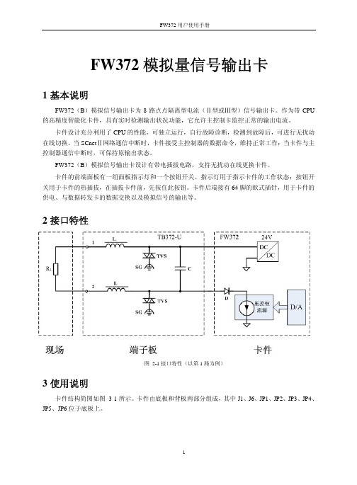
2接口特性图 2-1接口特性(以第1路为例)3使用说明卡件结构简图如图 3-1所示。
卡件由底板和背板两部分组成,其中J1、J6、JP1、JP2、JP3、JP4、JP5、JP6位于底板上。
图 3-1 FW372(B)结构简图3.1LED指示灯说明表 3-1指示灯说明3.2跳线表3-2 FW372(B)跳线设置跳1-2 正常工作状态JP1跳2-3 标定状态(用户禁止使用)跳1-2 单卡配置JP6跳2-3 冗余配置跳1-2 (HART通信保留)JP2,JP3跳2-3 (HART通信保留)跳1-2 (HART通信保留)JP4,JP5跳2-3 (HART通信保留)J1 跳7-8 IC1的下载接口,下载时连接下载线。
在正常工作中使用短路块连接7、8脚,其余引脚全部断开。
J6 IC2的下载接口,下载时连接下载线。
正常工作中全部断开跳1-2跳2-3J1跳7-8图 3-2 FW372(B)卡跳线示意图3.3端子板选择FW372(B)模拟信号输出卡在使用时必须与对应的端子板配合使用,端子板提供接线通道以及信号前级抗扰动处理。
FW372H使用手册
HART电流信号输出卡FW372H1基本说明FW372H卡是8路点点隔离HART电流信号输出卡,能够连接符合HART协议的现场总线的智能仪表进行网络设备管理和输出电流信号(Ⅲ型电流信号),并允许Rosemount的275型手持操作器作为第二主设备接入HART网络。
FW372H卡使用时占用机笼一个I/O槽位。
卡件可输出叠加了标准HART信号的电流信号,并且互不影响。
符合HART协议的信号经卡件处理后,通过RS-485/以太网转换器进入计算机。
通过跳线选择,卡件的RS-485通信线有两种连接方法:一种方法是从机笼母板上的RS-485接线端子引出;另一种方法是从与FW372H配套端子板上的RS-485接线端子上引出。
FW372H输出的电流信号实现对现场变送器的控制。
具体使用说明参见《FW372(B)使用手册》。
FW372H卡可单卡方式工作,也可冗余方式工作。
单卡工作方式下,卡件可插在16个I/O插槽的任一插槽内,冗余工作模式下,冗余的两块卡件必须插在相邻的两个I/O插槽中,且卡件在插槽中的地址应为ADD(偶数)与ADD+1(0≤ADD≤14)。
FW372H的HART上位机软件是SAMS智能设备管理软件。
通过该软件,用户可以方便快捷的组态、校准及检查现场的智能设备。
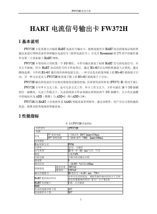
2性能指标表 2-1 FW372H性能指标卡件型号FW372H电源5V系统电源(5.0~5.3)DCV, Imax<250mA供电24V系统电源(24.0±0.7)VDC,Imax<300mA技术指标D/A转换方式PWM分辨率 12位,无极性信号类型 III型(4~20)mA气开、气关精度±0.1%FS自检功能开路自检及输出自检通道数8响应时间(10~90)%阶跃<100ms通道对地500V AC绝缘强度通道间250V AC输出负载能力 III型信号(4~20)mA 750Ω对单台仪表的组态、调校等操作响应时间小于2秒HART通讯响应时间读实时数据响应时间(8台)小于0.2秒HART仪表输入8路、点点隔离EMC抗电快速脉冲群干扰1kV抗浪涌冲击干扰2kV抗射频电磁波干扰10V/m抗静电放电干扰空气放电8kV,接触放电6kV其它工作温度(0~50)℃工作湿度(10~90)%,无凝露存储和运输温度(-40~+80)℃存储湿度(5~95)%,无凝露工作大气压(62~106)kPA3接口特性图 3-1接口特性图4使用说明卡件结构简图如图 4-1所示。
热点畜产电子刺激器用户指南说明书

Maintenance After Each Use:1. Thoroughly CLEAN AND DRY the Hot-Shot ® Livestock Prod after each use a. Remove shaft from handle and dry connection area of shaft and handleb. Wipe handle with a dry cloth, particularly around the trigger button and end cover areas 2. Inspect shaft tip for damage or excessive wear and replace as necessary3. Store with shaft separated from unit to allow for complete drying in areas that can’t be wiped dry4. The Hot-Shot ® Stock Prod handle may be stored lying down or hanging from the wrist strap, the shaft may be hung from shaft hang hole in the tipPeriodic Maintenance – Weekly or when the Hot-Shot ® Livestock Prod is exposed to excessive moisture:1. Disassemble the prod, clean and dry all parts. Clean and inspect all metal contacts for corrosion2. Inspect and check power level on alkaline batteries (we recommend using the Hot-Shot ® Battery Tester, part number R104)3. Inspect all parts for damage and replace as needed4. Allow to air dry before re-assembling5. Store with shaft separated from unit to allow for complete drying in areas that can’t be wiped dry6. The Hot-Shot ® Stock Prod handle may be stored lying down or hanging from the wrist strap, the shaft may be hung from shaft hang hole in the tipTesting Operation of the Hot-Shot ® Livestock Prod:1. Check that Prod is assembled correctly and that all connections are secure2. Remove trigger button safety clip3. Depress trigger and listen for the motor tone4. Touch both points to a metal surface, visible sparking on contact should occurRepairsHot-Shot ® maintains a complete repair service at the factory. If a Hot-Shot ® product fails due to defect within the specified warranty period, the unit must be returned to the factory for examination. If the product is found to be defective and is within the warranty period, replacement or repairs will be made. The product will be returned postage paid. For detailed warranty information visit Hot-Shot ® also maintains a repair for fee service at the factory. If a product is returned to the factory for repair and is not within the warranty period, customers will be contacted regarding estimated repair costs prior to chargeable repair service being performed. ReturnsIn the event a product needs to be returned to Hot-Shot® for a warranty claim:1. Enclose a note with the product that includes your name, full address and phone number2. Enclose proof of purchase receipt3. Send the product and above information to:Miller Mfg. Co.Attn: Repairs1450 West 13th Street Glencoe, MN 55336Or call 800-260-0888Animal end of shaftShaft Trigger Button Safety ClipTrigger ButtonHandle to Shaft attachment NutMotor, Batteries and Handle Case end capMotor, Batteriesand HandleProd Maintenance/Troubleshooting5640-MIL 3/08Symptom Possible Cause Possible FixWeak Spark/No SparkorProd makes no sound when trigger is depressed Batteries weakBad connectionBatteries not installed correctlyAlkaline: Check batteries with Hot-Shot® tester R104,replace if necessaryRechargeable: recharge battery packClean and inspect all connectionsCheck to see that the batteries are installed correctly per theinsertion diagram inside the caseMotor makes tone, but no spark at end of shaft Bad connectionBad shaftBad motorClean and inspect all connectionsCheck for spark at shaft connection point with shaftremoved, if present replace shaftCheck for spark at shaft connection point with shaftremoved, if none replace motorMotor making snapping sounds when shaft is not on animal or against steel Bad shaftShort Circuit due to moistureRemove shaft, if snapping stops clean/dry shaft. If snappingcontinues when shaft is reattached replace the shaftDisassemble Prod, clean and dry all connections,reassemble and testArcing between contacts onmotor or shaftBad shaftShort Circuit due to moisture Clean and dry shaft tip, if arcing still occurs at tip replace shaftDisassemble Prod, clean and dry all connections, reassemble and testBatteries getting HOT (please note that batteries getting warm during operation is normal)Batteries not installed correctlyShort CircuitCheck to see that the batteries are installed correctly per theinsertion diagram inside the caseClean and inspect all connections and check assembly ofprod to include all parts in caseUser receiving shock at handle during operation Short Circuit Clean and inspect all connections and check assembly ofprod to include all parts in case and ensure that all compo-nents are thoroughly dryProd still not functioning Damaged or Bad Motor and/or case Call Hot-Shot®customer support at 1-800-260-0888 or returnprod to retailer for repair Troubleshooting Guide:Carefully clean contacts in handle and on shaft Carefully clean contacts oncase, motor and batteriesCarefully clean contactson motor and end capClean and inspect battery contacts points. Secure contact strips to outside of notch so that they do not contact thecenter strip.Clean andinspect batterycontact points.For most recent version of the Hot-Shot® Maintenance and Troubleshooting Guide visit 。
浙大中控硬件DCS基础知识

2. DCS硬件(yìnɡ jiàn)介绍
2.3系统卡件介绍 2.3.2数据转发卡FW233
数据转发卡是系统卡件机笼的核心单元,是主控制卡连接I/O卡件的 中间环节,它一方面和主控卡进行通信,另一方面管理本机笼的I/O 卡件。通过数据转发卡可扩展1到8个卡件机笼,即可扩展最多128 块不同的I/O卡件。一个机笼必须(bìxū)配置一块(或冗余的一对) 数据转发卡 数据转发卡面板介绍 数据转发卡FW233面板上有5个指示灯和1个面板按钮。面板按钮又 叫切换开关,用于工作卡件和备用卡件之间的人工切换和插拔卡件 时通道保护按钮。面板示意图如下:
端子板
电源模块
第十二页,共50页。
2. DCS硬件(yìnɡ jiàn)介绍
2.2机柜、机笼及供电系统 机笼分为电源机笼和卡件机笼 电源机笼主要用来放置(fàngzhì)电源模块,一个机柜中只有一个电源机
笼,一个电源机笼最多可以配置4个电源模块,其中2个电源模块输 出5V电压,2个电源模块输出24V电压,他们一起给整个系统的卡件 和端子板以及母板等进行供电。 卡件机笼主体是由金属框架和母板构成,母板上安装有欧插,方便卡件 插拔。同一控制站的各个机笼通过SBUS网络相连。它主要放置 (fàngzhì)各类卡件,1个卡件机笼中有20个槽位,可放置(fàngzhì)2 块主控制卡、2块数据转发卡、16块I/O卡件。
该系统融合了最新的现场总线技术、嵌入式 软件系统、先进控制技术与网络(wǎngluò) 技术,实现了多种总线兼容和异构系统综合 集成。
第四页,共50页。
1. 浙大中控ESC-100 DCS简介 (jiǎn jiè)
第五页,共50页。
1. ESC-100 DCS简介(jiǎn jiè)
浙大中控一 ECS 100系统介绍-8
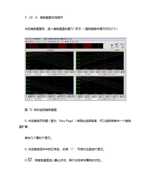
3.10.6、趋势画面浏览操作点击趋势图图标,进入趋势画面如图72 所示:(图的趋势布局方式为2*2)图72 实时监控趋势画面点击趋势页标题(图为“New Page”)将弹出选择菜单,可以选择将其中一个趋势图扩展,其他几个暂时不显示。
点击趋势控件中的位号名,去掉“√”,可使对应曲线不显示。
:使趋势画面进入静止状态,再次点击将恢复实时状态。
:显示前一页或后一页趋势画面。
:选择每次翻过一页的百分之几。
:减少和增加记录点数。
记录点数越多,趋势曲线越紧缩。
:选择在控件中显示哪个位号的纵坐标。
:时间和位号设置(图73 所示)。
图73 历史趋势时间和位号设置对话框起始时间、终止时间:用于选择需要查看的曲线段,在显示的有效范围内起始时间应比终止时间小100 秒以上。
时间间隔:单位为:时:分:秒,不能超过23:59:59。
数据点数:范围在100~1200 之间。
位置格式:可以选择在曲线图里面或是外面。
显示间隔:1~10 之间的整数。
终止时间-起始时间=时间间隔*数据点数。
:设置趋势图的显示特性。
如图74所示图74 趋势设置趋势布局:分别对一些选项进行选择,包括是否显示滑动条、工具条、数值坐标、时间坐标等以及显示的各位号信息进行设置。
数值坐标设置:对数值坐标的上下限及其他内容进行设置。
曲线图设置:对颜色、网格线及网格进行设置。
:趋势图画面刷新。
:打印属性设置,如图75 所示,设置完毕后,点击确定即可打印指定位号的趋势曲线。
图75 趋势图打印设置3.11、附录:系统各类卡件的功能、安装方法,拨码、跳线设置方法:1、主控卡FW243:地址范围2-31,周期100ms-5s2、主控卡FW243X:地址范围2-127,周期50ms-5s3、主控卡FW247:地址范围2-127,周期50ms-5s4、数据转发卡FW233地址范围0-155、数据转发卡FW233地址范围0-156、标准信号输入卡FW351:接收8路点点隔离的标准II、III型电压、电流信号。
CH372DS2
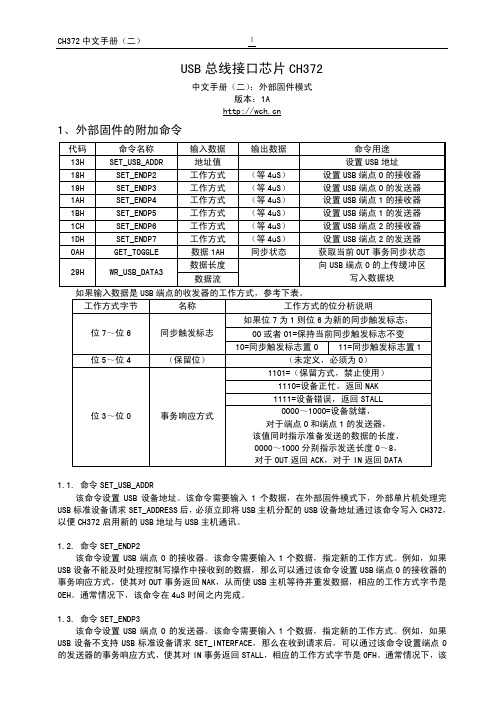
USB总线接口芯片CH372中文手册(二):外部固件模式版本:1A1、外部固件的附加命令代码命令名称输入数据输出数据命令用途13H SET_USB_ADDR 地址值设置USB地址18H SET_ENDP2 工作方式(等4uS)设置USB端点0的接收器19H SET_ENDP3 工作方式(等4uS)设置USB端点0的发送器1AH SET_ENDP4 工作方式(等4uS)设置USB端点1的接收器1BH SET_ENDP5 工作方式(等4uS)设置USB端点1的发送器1CH SET_ENDP6 工作方式(等4uS)设置USB端点2的接收器1DH SET_ENDP7 工作方式(等4uS)设置USB端点2的发送器0AH GET_TOGGLE 数据1AH 同步状态获取当前OUT事务同步状态数据长度29H WR_USB_DATA3数据流向USB端点0的上传缓冲区写入数据块如果输入数据是USB端点的收发器的工作方式,参考下表。
工作方式字节名称工作方式的位分析说明如果位7为1则位6为新的同步触发标志:00或者01=保持当前同步触发标志不变位7~位6 同步触发标志10=同步触发标志置0 11=同步触发标志置1 位5~位4 (保留位)(未定义,必须为0)1101=(保留方式,禁止使用)1110=设备正忙,返回NAK1111=设备错误,返回STALL位3~位0 事务响应方式0000~1000=设备就绪,对于端点0和端点1的发送器,该值同时指示准备发送的数据的长度,0000~1000分别指示发送长度0~8,对于OUT返回ACK,对于IN返回DATA1.1. 命令SET_USB_ADDR该命令设置USB设备地址。
该命令需要输入1个数据,在外部固件模式下,外部单片机处理完USB标准设备请求SET_ADDRESS后,必须立即将USB主机分配的USB设备地址通过该命令写入CH372,以便CH372启用新的USB地址与USB主机通讯。
USC 20 20-TB 3 机械切割器说明书

2. Make certain the machine is properly grounded. 3. Before operating the machine, remove ties, rings, watches, other jewelry, and roll up
sleeves above the elbows. Remove all loose clothing and confine long hair. Do not wear gloves. 4. Keep the floor around the machine clean. 5. Keep machine guards in place at all times when the machine is in use. 6. Do not over reach. Maintain a balanced stance at all times so that do not fall or lean against blades or other moving parts. 7. Make all machine adjustments or maintenance with the machine unplugged from the power source. 8. Replace warning labels if they become obscured or removed. 9. Make sure the power source switch is in the OFF position before connecting the machine to the power source. 10. Make a habit of checking to see that the keys and adjusting wrenches are removed before turning on the machine. 11. Keep belt guard and blade guards in place and in working order. 12. Failure to comply with all of these warning could lead to serious injury.
XP372 使用手册

JX-300XP系统XP372使用手册浙江中控技术股份有限公司声 明⏹ 严禁转载本手册的部分或全部内容。
⏹ 在不经预告和联系的情况下,本手册的内容有可能发生变更,请谅解。
⏹ 本手册所记载的内容,不排除有误记或遗漏的可能性。
如对本手册内容有疑问,请与我公司联系,联系邮箱:SMS@ 。
商 标中控、SUPCON 、SPlant、 Webfield 、ESP-iSYS 、MultiF 、InScan 、SupField 以上商标或标识均是浙江中控技术股份有限公司已经注册或已经申请注册或正在使用的商标和标识,拥有以上商标的所有权,未经浙江中控技术股份有限公司的书面授权,任何个人及企业不得擅自使用上述商标,对于非法使用我司商标的行为,我司将保留依法追究行为人及企业的法律责任的权利。
文档标志符定义警告:标示有可能导致人身伤亡或设备损坏的信息。
WARNING : Indicates information that a potentially hazardous situation which, if not avoided, could result in serious injury or death.电击危险:标示有可能产生电击危险的信息。
RISK OF ELECTRICAL SHOCK: Indicates information that Potential shock hazard where HAZARDOUS LIVE voltages greater than 30V RMS, 42.4V peak, or 60V DC may be accessible.防止静电:标示防止静电损坏设备的信息。
ESD HAZARD: Indicates information that Danger of an electro-static discharge to which equipment may be sensitive. Observe precautions for handling electrostatic sensitive devices注意:提醒需要特别注意的信息。
TB温控器简易中文手册[1]
![TB温控器简易中文手册[1]](https://img.taocdn.com/s3/m/d62a1846fe4733687e21aa3a.png)
TB系列控制器參數區操作說明:如何修改溫度設定點 ?在通常顯示下, 按左移鍵"一次" , SV值個位數閃爍, 閃爍的數字才可利用▲或▼鍵更改之, 欲更改十位數, 百位數或千位數字, 可再利用左移鍵移到該位元上, 再利用▲或▼鍵更改之, 設定完成請再按 SET 鍵"一"次, 即可回到通常顯示。
TB系列第一層參數群 :要進入第一層參數群, 押 SET 鍵一下即可。
變更設定參數後, 必須再押 SET 鍵, 才有完成輸入。
代號說明原始值At Yes:執行自動演算, NO:停止自動演算NOAL1 第一組警報設定值(全刻度) 0要離開第一層參數群, 押 SET 鍵一下即可。
TB系列第二層參數群 :要進入第二層參數群, 押 SET 鍵5秒以上即可。
變更設定參數後, 必須再押 SET 鍵, 才有完成輸入。
代號說明原始值p 加熱側比例帶0 - 200.0%, 0=ON/OFF 30HYS1 主輸出不感帶, P=0時為on-off控制, 才有此參數出現0I 加熱側積分時間0-3600秒, 0=積分動作OFF 240d 加熱側微分時間0 - 900秒, 0=微分動作OFF 60db1 不用設定AtuL 自動演算偏移值全刻度 0=SV 值0CytL 加熱側比例週期0 - 150秒Relay = 15 SSR = 14~20mA = 0LCK 參數群鎖定0000 - 11110000要離開第二層參數群, 押 SET 鍵5秒以上即可。
TB系列第三層參數群要進入第三層參數群, 同時按SET 鍵+左移鍵6秒以上即可。
變更設定參數後, 必須再押SET 鍵, 才有完成輸入。
代號說明原始值INP1INP1 輸入信號選擇, 請參照入力種類表可視輸入之TYPE而自行設定之L.SP.LLSPL 使用溫度範圍下限0或可自行定設U.SP.L USPL 使用溫度範圍上限可自行設定ALd1ALD1 第一組警報種類, 請參照警報種類表11 (為偏差高溫警報)ALt1 ALT1 警報動作時間, 一般設定99分59秒99分59秒 HYSA HYSA 警報不趕感帶, 0 ~ 1000 ℃0PVOS PVOS 入力值補正(全刻度) 0UNIt UNIT 單位切換℃ 或 ℉℃OUD OUD正逆動作選擇HEAT-逆動作, COOL -正動作 HEAT OPAD OPAD PID與FUZZY選擇 PID H= HZ 電源頻率60/50Hz選擇 60Hz 要離開第三層參數群, 同時按SET 鍵+左移鍵6秒以上即可。
浙江中控ECS-100系统硬件介绍

冗余
TB352-RU
8
配套端子板 TB352-U
◆16 路端子板,供2块不冗余FW352用。
端子板上有冷端补偿电路,可对冷端温度进行补偿。
配套端子板 TB352-RU
◆8 路端子板,供2块冗余FW352用。
端子板上有冷端补偿电路,可对冷端温度进行补偿。
热电阻信号输入卡
热电阻信号输入卡
• FW353
数据转发卡
冗余配置: 单卡配置:
IO卡及端子板
IO卡及端子板
IO卡及端子板
IO卡
系统信号线缆
端子板
现场信号
IO卡及端子板
•(1)信号类型
按状态分:
模拟量(Analog) :随时间连续变化信号(如电压,电流等信号) ;
数字量(Digital):0、1表示通断 (ON\OFF),可称开关量;
单卡
TB351-IU
16
电流
冗余
TB351-IRU
8
配电:向现场变送器输出 24V 配电时必须安装配电模块PM-351I
PM-351I
配套端子板 TB351-IU
◆16路端子板,供2块不冗余FW351使用。
DB 1
DB2
J4
73
76
2 J1 1
32 34 J3 40 42 31 33 39 41
J2
72 71
配套端子板 TB351-IRU
◆8 路端子板,供2块冗余FW351使用。
热电偶信号输入卡
热电偶信号输入卡
• FW352(B)
性能说明:
信号类型:
-20~+20 /-100~+100mV
各类热电偶(E/J/K/S/T等) 测量精度:±0.2%FS
TB372-E8R使用手册

安全栅底板TB372-E8R1概述TB372-E8R为8路隔离式安全栅底板,可供1对冗余配置或1块不冗余配置的FW372(B)卡使用;TB372-E8R可以安装8个MTL4000系列模拟量输出型隔离栅。
来自卡件系统侧(4 ~20)mA 输入,本安侧(4 ~20)mA输出,带HART。
2技术特性表 2-1 性能指标模块类型TB372-E8R指标项指标说明备注通道数8点配合的隔离栅类型MTL4046C(输入、输出、电源三隔离)SB4046-EX(输入、输出、电源三隔离)系统侧4 mA ~20mA 输入,本安侧4mA ~20mA输出,带HART供电电压 24VDC(冗余)带熔断式保险丝规格 153.5mm×151.5mm工作温度0℃~60℃3接口特性图图 3-1接口特性图(MTL4046C隔离安全栅)在接口特性图中,当使用不同的隔离栅时,隔离栅部分的图示有所不同,具体请参见相应隔离栅的说明书。
4使用说明4.1安全栅底板外观图TB372-E8R安全栅底板结构外形如图4-1所示。
图4-1 TB372-E8R安全栅底板结构外形图J1为卡件与隔离栅数据连线插座,J1R为冗余卡数据连线插座。
D3指示灯为TB372-E8R安全栅底板的供电指示灯,D3亮则表示24V供电正常,D3灭则表示24V供电异常。
M1~M8为隔离栅插座,其中M1上的隔离栅对应的通道对应卡件的第1通道,M8上的隔离栅对应的通道对应卡件的第8通道。
4.2接插件说明TB372-E8R安全栅底板接插件说明如表4-1所示。
表4-1TB372-E8R 安全栅底板接插件说明标号 说 明 J1 单卡数据连线插座 J1R 冗余卡数据连线插座 J2 供电电源接线端子 M1~M8隔离栅插座4.3 端子定义TB372-E8R 安全栅底板接线端子说明如表 4-2所示。
隔离栅接入外配电时,可从J2 的1、2号端子或者3、4号端子接入一路外部24V 电源。
“24V A ”和“24VB ”表示接外部24V 正端,“VS-”表示接外部24V 负端,当需要接入冗余的外配24V 电源时,可同时从1、2号端子和3、4号端子分别接入。
燃烧器说明书

意大利利雅路强制通风燃气燃烧器RS70-130编号型号类型3785102 RS70 821 T13785103 RS70 821 T13785302 RS100 822 T13785303 RS100 822 T13785502 RS130 823 T13785503 RS130 823 T11)参考条件:环境温度20℃,表压1000mbar,海拔100m。
2)测试点16(A)p.3处的压力为零,燃气环2)(B)p7开启,燃烧器输出功率最大。
3)制造商在燃烧室中所测得的噪音等级是燃烧器运行在测试锅炉上,且处于最大额定输出功率上测定的。
LPG运行的组件(可选)燃烧出力RS70-100-130型燃烧器有两种工作方式:1段火和2段火。
最大输出功率必须在区域A中选择。
为了也要利用区域B(RS130)则有必要执行P6中所解释的燃烧头校准。
最小输出功率不得低于该图中的最小功率限制。
RS70=192KWRS100=232KWRS130=372KW重要燃烧出力的数值范围是根据以下条件获得的:环境温度20℃,大气压力1000mbar(海拔约为100m)并且燃烧头的调整如p7所示。
测试锅炉(B)根据EN676标准,燃烧出力的设定与特定的测试锅炉有关。
商用锅炉如锅炉是CE型认可的,且其燃烧器尺寸与图B中所示相似,则燃烧器/锅炉的组合不会引起任何问题。
如燃烧器必须用于没有经过CE认可的,或其燃烧尺寸小于(B)图中所示的商用锅炉相结合,则请咨询制造商。
燃烧其描述(A)1.燃烧头2.点火电极3.燃烧头调整用螺钉4.过渡段5.控制燃气蝶阀和风门的伺服电动机(通过调节可变凸轮机构)当燃烧器停机时,风门将完全关闭以降低由于流动气流所造成的热损失(将会从风机的空气入口吸入空气)6.滑杆的延伸段7.电功机接触器和带有复位的热继电器8.离子探针电缆连接器9.接线端子10.接线孔11.两个开关:燃烧器开关;大小火开关12.带锁定指示灯和复位按钮的控制盒13.火焰检查窗口14.最低空气压力开关(差动式)15.打开燃烧器以及监察燃烧头的滑杆16.燃气压力测试点和燃烧头固定螺钉17.空气压力测试点18.火焰传感器19.风门20.风机空气入口21.将风机固定到过渡段套筒上的螺钉22.燃气输入管道23.燃气蝶阀24.与锅炉安装的法兰25.稳焰盘可能发生的两种类型的燃烧器故障:控制盒锁定如控制盒21)(A)按钮亮,表明燃烧器处于锁定状态。
TB系列温控器操作手册说明书

微電腦程序控制器操作手冊TB100 TB600 TB700 TB400 TB900在使用本控制器之前,請先確定控制器的輸入輸出範圍和輸入輸出種類與您的需求是相符的。
1. 面板說明1.1 七段顯示器PV :處理值(process value),紅色4位顯示 SV :設定值(setting value),綠色4位顯示.21.2 LED LED LEDOUT1 :第一組輸出(Output1),綠色燈OUT2 :第二組輸出(Output2),綠色燈 AT :自動演算(Auto Tuning),黃色燈PRO :程式執行中(Program),黃色燈 ----- 只適用於 P TB 系列 AL1 :第一組警報(Alarm 1),紅色燈 AL2 :第二組警報(Alarm 2),紅色燈MAN :輸出百分比手動調整(Manual),黃色燈※注意:當發生錯誤(Error)時,MAN 燈會亮,並將輸出百分比歸零1.3 按鍵SET:設定鍵(寫入設定值或切換模式) :移位鍵(移動設定位數):增加鍵(設定值減1):減少鍵(設定值加1) A/M :自動(Auto)/手動(Manual)切換鍵。
自動:輸出百分比由控制器內部演算決定手動:輸出百分比由手動調整OUTL(在User Level 中)決定2 自動演算功能(Auto tuning)2.2 需先將AT(在User Level 中)設定為YES ,啟動自動演算功能。
2.3自動演算結束後,控制器內部會自動產生一組新的PID 參數取代原有的PID 參數。
* 自動演算適用於控溫不準時,由控制器自行調整PID 參數。
2.4 ATVL:自動演算偏移量(AutoTuning offset Value)SV減ATVL為自動演算設定點,設定ATVL可以避免自動演算時,因PV值震盪而超過設定點(Overshoot)。
例如:SV=200℃,ATVL=5,則自動演算設定點為195℃當自動演算中,PV值震盪,則是在195℃上下震盪,因此可避免PV值震盪超過200℃。
雷达蓝传输系统产品说明书
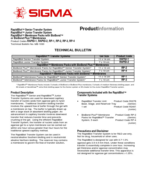
RapidBlot™ Senior Transfer System RapidBlot™ Junior Transfer SystemRapidBlot™ Membrane Packs with BioBond™or BioBond Plus™ MembranesProduct Codes RAPID-1, RAPID-2, RP-1, RP-2, RP-3, RP-4Technical Bulletin No. MB-1030TECHNICAL BULLETINRapidBlot™ Transfer Systems Gel SizeProduct CodeRapidBlot Senior Transfer System 11 x 14 cm RAPID-1RapidBlot Junior Transfer System 7 x 10 cmRAPID-2RapidBlot™ Membrane Packs with BioBond Plus™ MembranesBioBond Plus Membrane Packs for RapidBlot Senior Transfer System*11 x 14 cm RP-2BioBond Plus Membrane Packs for RapidBlot Junior Transfer System*7 x 10 cm RP-4RapidBlot™ Membrane Packs with BioBond ™ MembranesBioBond Membrane Packs for RapidBlot Senior Transfer System*11 x 14 cm RP-1BioBond Membrane Packs for RapidBlot Junior Transfer System*7 x 10 cm RP-3* RapidBlot ™ Membrane Packs include: 5 sheets of BioBond or BioBond Plus membrane, 5 sheets of medium thickness blotting paper, and 80 sheets of QuickDraw ™ extra thick blotting paper for the Senior system or 65 sheets for the Junior RapidBlot Transfer system.Product DescriptionThe RapidBlot ™ Senior and RapidBlot ™ Junior Transfer Systems are used for downward capillary transfer of nucleic acids from agarose gels to nylon membranes. Traditional Southern blotting transfer involves the upward flow of buffer through the gel with a membrane on top. The buffer is typically drawn up with a large stack of absorbent blotting paper. An advancement in capillary transfer involves downward transfer that reduces transfer time and prevents crushing of the gel. Using the efficient RapidBlotTransfer System, the transfer of nucleic acids from an agarose gel to a nylon membrane can be carried out within one hour versus greater than four hours for the traditional upward capillary method.The RapidBlot Transfer System can be used inneutral/alkaline Southern blotting and in neutral/mild alkaline Northern blotting. The reservoir tray contains a membrane to govern the flow of transfer solution .Components Included with the RapidBlot ™Transfer Systems •RapidBlot Transfer Unit: Product Code R2276Base, Stage, and Reservoir Tray (Senior)1 set Product Code R2401(Junior)• BioBond Plus Membrane Product Code RP-2Packs for RapidBlot Transfer (Senior)System, 5 each Product Code RP-4(Junior)Precautions and DisclaimerThe RapidBlot Transfer System is for R&D use only.Not for drug, household or other uses.The RapidBlot is designed for use with 0.7-1.0%agarose gels 3.5-4.5 mm thick. Under these conditions transfer is essentially complete in one hour. Increasing gel thickness and/or agarose concentration maynecessitate additional transfer time. This apparatus is not designed for agarose gel concentrations >1.25%.Product Information2Reagents that May be Required, but are Not Provided Product NameProduct Code Depurination Solution for Neutral Southern TransferN 1907Denaturation Solution for Neutral Southern TransferN 1531Neutralizing Solution for Neutral Southern TransferN 1532Transfer Solution for Neutral Southern TransferN 0907Transfer Solution for Alkaline Southern TransferA 7967Neutralizing Solution for Alkaline Southern TransferA 8092Neutral Northern Transfer SolutionN 6531Mild Alkaline Northern Transfer Solution A 8217Mild Alkaline Northern Wash Solution A 8342SSC Buffer, 20X ConcentrateS 6639Storage/StabilityThe RapidBlot Transfer unit is made of a high density polyethylene and may be stored at room temperature.The membrane, which governs the flow of the transfer solution, is stable for at least 50 transfers.Preparation Instructions1. 2X SSC for DNA solutions. Prepare 2X SSC bydiluting 50 ml of 20X SSC with 450 ml of distilled,deionized water.* Pre-wet in Transfer Solution** Sr - 12 sheets and Jr - 15 sheetsFigure 13Assembly DirectionsRefer to Figure 1a. The Stage fits at the bottom of the Base.b. Center 12 sheets for the RapidBlot Senior and15 sheets for the RapidBlot Junior of dryQuickDraw TM blotting paper on the Stage.c. Pre-wet 1 sheet of QuickDraw in theappropriate transfer solution for 10 secondsand place on top of the dry QuickDraw sheets.d.Pre-wet BioBond TM membrane in appropriatetransfer solution and place on top of the pre-wet QuickDraw.e.Center Agarose gel on the pre-wet BioBondmembrane. Smooth out any air bubbles toallow an even, efficient transfer. Note: Addingextra transfer solution to the membrane beforeplacing the gel reduces the formation ofbubbles.f. Pre-wet Medium Thickness Blotting Paper inappropriate transfer solution for 10 seconds,and place on top of the agarose gel.g. Place Reservoir Tray level on top of base andmedium thickness blotting paper. Check forcontact between the Reservoir Tray and theblotting paper.h. Fill Reservoir Tray with 170 ml of appropriatetransfer solution for a RapidBlot Senior or70 ml for a RapidBlot Junior.ProcedureA.Neutral Southern Blotting1. Prepare DNA for analysis by electrophoresis in anagarose gel containing the appropriatepercentage of agarose to resolve the bands ofinterest. For larger fragments (≥1 kb) use 0.7%agarose and for smaller fragments (0.3-3 kb), use0.8-1.0% agarose. If using BlueView Nucleic AcidStain, 10X TBE Buffer (Product Code T 9060) or10X TAE Buffer (Product Code T 8935), see thetechnical bulletin for those products for details ofelectrophoresis. Ethidium bromide staining is notnecessary for BlueView agarose gels.2. Stain gel in a solution of 0.5 µg/ml ethidiumbromide for 30 minutes at room temperature andvisualize with ultraviolet light.Note: Steps 3-5 should be performed at roomtemperature with gentle agitation.3. Depurination: If the fragments of interest arelarger than 10 kb, the DNA should be nicked bydepurination prior to transfer. To depurinate theDNA, soak the gel in several gel volumes ofDepurination Solution for 10 minutes at roomtemperature or at least until bromophenol blueindicator turns yellow.4. Denaturation: Denature the DNA by soaking thegel for 30 minutes in several gel volumes ofDenaturing Solution.5. Neutralization: Briefly rinse the gel with deionizedwater to remove any residual denaturation buffer.Neutralize by soaking the gel for 30 minutes inseveral gel volumes of Neutralizing Solution.6. Assemble the RapidBlot Transfer System (refer toAssembly Directions) using Transfer Solutionfor Neutral Southern Transfer (Product CodeN 0907).7. Allow 1 hour for the transfer.8. After transfer is complete, dismantle the reservoirtray and pour off the extra buffer. Peel off themedium thickness blotting paper and dispose.Carefully remove the gel. Carefully remove themembrane with tweezers and place on blottingpaper. Dispose of the QuickDraw sheets. Rinseeach tray with deionized water, sincecrystallization of the transfer solution on thereservoir tray could affect the future performanceof the flow-regulating membrane.9. Rinse the membrane in 2X SSC for severalminutes to remove any pieces of gel.10. Allow membrane to air dry several minutes. Topermanently affix the DNA to the membrane,bake at 80°C for 30 minutes and/or irradiate themembrane (DNA side toward the light source)with 130 mJoules of 254 nm ultraviolet light.BioBond Plus nylon membranes do not requirecrosslinking of the DNA.411. The membrane can be stored at roomtemperature between clean pieces of blottingpaper until needed. For extended use, store blotsdesiccated at 2-8°C.12. To evaluate the efficiency of transfer, the gel may berestained in a solution of 0.5 µg/ml ethidium bromide for30 minutes at room temperature and visualized withultraviolet light.B.Alkaline Southern Blotting1. Prepare DNA for analysis by electrophoresis inan agarose gel containing the appropriatepercentage of agarose to resolve the bands ofinterest. For larger fragments (≥1 kb) use 0.7%agarose and for smaller fragments (0.3-3 kb), use0.8-1.0% agarose. If using BlueView nucleic acidstain, 10X TBE Buffer (Product Code T 9060) or10X TAE Buffer (Product Code T 8935), see thetechnical bulletin for those products for details ofelectrophoresis. Ethidum bromide staining is notnecessary for BlueView agarose gels.2. Stain gel in a solution of 0.5 µg/ml ethidiumbromide for 30 minutes at room temperature andvisualize with ultraviolet light.Note: Steps 3 and 4 should be performed at roomtemperature with gentle agitation.3. Depurination: If the fragments of interest arelarger than 10 kb, the DNA should be nicked bydepurination prior to transfer. To depurinate theDNA, soak the gel in several gel volumes ofDepurination Solution for 10 minutes at roomtemperature or at least until bromophenol blueindicator turns yellow.4. Denaturation: Briefly rinse the gel with deionizedwater to remove any residual running ordepurination buffer. Denature the DNA bysoaking the gel for 30 minutes in several gelvolumes of Transfer Solution for AlkalineSouthern Transfer.5. Assemble the RapidBlot Transfer System (refer toAssembly Directions) using Transfer Solutionfor Alkaline Southern Transfer (Product CodeA7967).6.Allow 1 hour for the transfer.7.After transfer is complete, dismantle the reservoirtray and pour off the extra buffer. Peel off themedium thickness blotting paper and dispose.Carefully remove the gel. Carefully remove themembrane with tweezers and place on blottingpaper. Dispose of the QuickDraw sheets. Rinseeach tray with deionized water, sincecrystallization of the transfer solution on theReservoir Tray could affect the future performance of the flow-regulating membrane.8. Rinse the membrane in 2X SSC for severalminutes to remove any pieces of gel.9. Allow membrane to air dry several minutes. Topermanently affix the DNA to the membrane,bake at 80°C for 30 minutes and/or irradiate themembrane (DNA side toward the light source)with 130 mJoules of 254 nm ultraviolet light.BioBond Plus nylon membranes do not requirecrosslinking of the DNA.10. The membrane can be stored at roomtemperature between clean pieces of blottingpaper until needed. For extended use, storeblots desiccated at 2-8°C.11. To evaluate the efficiency of transfer, the gel maybe restained in a solution of 0.5 µg/ml ethidiumbromide for 30 minutes at room temperature andvisualized with ultraviolet light.C.Neutral Northern BlottingNote: Always use standard procedures to preventRNase contamination throughout this protocol.To make the RapidBlot unit RNase-free, wash the unit in detergent, rinse completely with deionized water and dry with ethanol. Soak the unit pieces in 3% hydrogen peroxide for 10 minutes at room temperature, then rinse completely with deionized water treated with0.1% DEPC. Do not treat RapidBlot unit directly with DEPC or autoclave. It is recommended to purchase two separate units for doing Northern and Southern transfers.51.Perform electrophoresis with RNA in formaldehydeor glyoxal/ DMSO gels according to publishedprocedures (e.g. Sambrook, et al.). The addition of formaldehyde to MOPS (Product Code M 3183)buffered gels is not required when RNA has beendenatured 10 minutes at 65°C in RNA SampleLoading Buffer (Product Code R 4268) prior toloading.2.For RNA gels containing formaldehyde, wash thegel twice for 15 minutes in several gel volumes ofRNase free water to remove residualformaldehyde. Glyoxal/DMSO gels do not requireany pretreatment.3. Stain gel in a solution of 0.5 µg/ml ethidiumbromide for 30 minutes at room temperature andvisualize with ultraviolet light.4. Assemble the RapidBlot Transfer System (refer toAssembly Directions) using Neutral NorthernTransfer Solution (Product Code N 6531).5. Allow 1 hour for the transfer.6. After transfer is complete, dismantle the reservoirtray and pour off the extra buffer. Peel off anddispose the medium thickness blotting paper.Carefully remove the gel. Carefully remove themembrane with tweezers and place on blottingpaper. Dispose of the QuickDraw sheets. Rinseeach tray with deionized water, sincecrystallization of the transfer solution on thereservoir tray could affect the future performanceof the flow-regulating membrane.7. Rinse the membrane in 2X SSC for severalminutes to remove any pieces of gel.8. Allow membrane to air dry several minutes. Topermanently affix the RNA to the membrane,bake at 80°C for 30 minutes and/or irradiate themembrane (RNA side toward the light source)with 130 mJoules of 254 nm ultraviolet light.BioBond Plus nylon membranes do not requirecrosslinking of the RNA.9. The membrane can be stored at roomtemperature between clean pieces of blottingpaper until needed. For extended use, storeblots desiccated at 2-8°C.10. To evaluate the transfer efficiency, the gel maybe restained in a solution of 0.5 µg/ml ethidiumbromide for 30 minutes at room temperature andvisualized with ultraviolet light.d Alkaline Northern BlottingNote: Always use standard procedures to prevent RNase contamination throughout this protocol. See Section C for detailed instructions on the preparationof the RapidBlot unit.1. Perform electrophoresis with RNA informaldehyde or glyoxal/DMSO gels according topublished procedures (e.g. Sambrook, et al.).The addition of formaldehyde to MOPS (ProductCode M 3183) buffered gels is not required whenRNA has been denatured 10 minutes at 65°C inRNA Sample Loading Buffer(Product Code R4268) prior to loading.2. For RNA gels containing formaldehyde, wash thegel twice for 15 minutes in several gel volumes ofRNase free water to remove residualformaldehyde. Glyoxal/DMSO gels do not require any pretreatment.3. Stain gel in a solution of 0.5 µg/ml ethidiumbromide for 30 minutes at room temperature andvisualize with ultraviolet light.4. Assemble the RapidBlot Transfer System (refer toAssembly Directions) using Mild AlkalineNorthern Transfer Solution (Product CodeA8217).5. Allow 1 hour for the transfer.6. After transfer is complete, dismantle thereservoir tray and pour off the extra buffer. Peeloff the medium thickness blotting paper anddispose. Carefully remove the gel. Carefullyremove the membrane with tweezers and placeon blotting paper. Dispose of the QuickDrawsheets. Rinse each tray with deionized water,since crystallization of the transfer solution onthe reservoir tray could affect the futureperformance of the flow-regulating membrane. 7. Rinse the membrane in Mild Alkaline NorthernWash Solution for several minutes to remove anypieces of gel.68.Allow membrane to air dry several minutes. To permanently affix the RNA to the membrane, bake at 80°C for 30 minutes and/or irradiate themembrane (RNA side toward the light source) with 130 mJoules of 254 nm ultraviolet light. BioBond Plus nylon membranes do not require crosslinking of the RNA.9.The membrane can be stored at roomtemperature between clean pieces of blotting paper until needed. For extended use, store blots desiccated at 2-8°C.10. To evaluate the transfer efficiency, the gel maybe restained in a solution of 0.5 µg/ml ethidium bromide for 30 minutes at room temperature and visualized with ultraviolet light.Troubleshooting Guide Problem CauseSolutionDNA fragments are too large Depurinate gel before transfer or increase the depurination time.Gel is too thick (over 4.5 mm)Use a thinner gel or increase the transfer time.Agarose gel concentration is too high Use a lower concentration or increase the transfer time.This apparatus is not designed for agarose gel concentrations >1.25%.Stack is not contacting reservoir tray Add more height to the bottom of the QuickDraw stack.Crushing of the gelReduce the height of the QuickDraw stack by removing single sheets of QuickDraw until the stack is the correct height.Incomplete transferNot enough transfer solution Add more solution to the reservoir tray.Uneven transfer Reservoir tray not levelMake sure the reservoir tray is level during transfer.Non-specific binding of probe to target nucleic acidsAdd sheared, denatured salmon testes DNA (Product Code D 7656) to a final concentration of 100 µg/ml in prehybridization and hybridization solutionsHighbackgroundWash conditions are not sufficiently stringentAdd an ultra-high stringency wash step (0.1X SSC,0.1% SDS). Wash for 20 minutes at hybridization temperature. Increase the temperature of the hybridization and/or washes.Probe was not labeled efficientlyCheck that the specific activity of radiolabeled probes is>5 x 10⁸cpm/µg. For non-radioactive probes, check the incorporation of hapten by spotting and detecting serial dilutions of probe in direct comparison to aknown standard. If probes are not labeled well enough,remake and confirm adequate incorporation rates.Target nucleic acids are not present,have been degraded, or are too low for detectionRun agarose gel electrophoresis to confirm nucleic acids are not degraded. Load more target nucleic acids for blotting. For Northern blots, up to 30 µg of total RNA can be loaded per laneWeak or absent signalNon-radioactive detection system is not working properlyConfirm the enzyme/antibody conjugate is functioning properly by spotting and detecting the labeled probe on nylon membrane. If the enzyme/antibody conjugate is functional, check the chemiluminescent substrate by spotting the enzyme/antibody conjugate on a membrane and detecting with the substrate in question.7General ReferencesChomczynski, P., One-hour downward alkaline capillary transfer for blotting of DNA and RNA. Anal. Biochem., 201, 134-139 (1992)Chomczynski, P. and Mackey, K., One-hour downward capillary blotting of RNA at neutral pH. Anal. Biochem., 221, 303-305 (1994)Lichtenstein, A.V., et al., A procedure for DNA and RNA transfer to membrane filters avoiding weight-induced gel flattening. Anal. Biochem., 191, 187-191 (1990)Meinkoth, J. and Wahl, G., Hybridization of nucleic acids immobilized on solid supports. Anal. Biochem., 138, 267 (1984)Southern, E.M., Detection of specific sequences among DNA fragments separated by gel electrophoresis. J. Mol.Biol., 98, 503-517 (1975)Sambrook, J, et al. Molecular Cloning: A Laboratory Manual, Third Edition, Cold Spring Harbor Laboratory Press, New York (2000) (Product Code M 8265)Related ProductsProduct Name Product CodeQuickDraw™ Extra Thick Blotting Paper P 7796, P 6803, P 7921Medium Thickness Blotting Paper P 6664DNA gel loading solution G 7654RNA sample loading buffer R 426810X TBE Buffer T 4415MOPS-EDTA-sodium acetate buffer M 5755T 9060BlueView Nucleic Acid Stain, 10X TBEBufferT8935BlueView Nucleic Acid Stain, 10X TAEBufferSouthern Breeze™ Blotting Kits SBRZ-1A, SBRZ-1B, SBRZ-2A, SBRZ-2BAlkaline Southern Breeze™ Blotting Kits ASBRZ-1A, ASBRZ-1B, ASBRZ-2A,ASBRZ-2BNorthern Breeze™ Blotting Kits NBRZ-1A, NBRZ-1B, NBRZ-2A,NBRZ-2BPerfectHyb Plus™ Hybridization Buffer H 7033CDP-Star™ Universal Detection Kit U-ALKN 8530, N 9155, N 8405, N 9280All-in-One™ Nick Translation LabelingMixesAll-in-One Random Prime Labeling Mixes R 7522, R 9647, R 7022, R 9522BioBond™ Plus Nylon Membranes N 5281, N 5781, N 5406, N 5531, N 5656BioBond™ Nylon Membranes N 1406, N 4031, N 3656, N 3781, N 3906UniScript™ Transcription Kits US-T3, US-T7, US-SP6Precast Agarose Gels P 5472, P 5722, P 6222, P 5972E 1385Ethidium Bromide, aqueous solution,500 µg/mlJM 5/01Sigma brand products are sold through Sigma-Aldrich, Inc.Sigma-Aldrich, Inc. warrants that its products conform to the information contained in this and other Sigma-Aldrich publications.Purchaser must determine the suitability of the product(s) for their particular use. Additional terms and conditions may apply.Please see reverse side of the invoice or packing slip.。
rts372r10说明书

rts372r10说明书说明书模板
标题:产品说明书
一、产品概述
(1)产品背景
(2)产品功能
(3)产品特点
(4)产品应用范围
二、产品组成和配件
(1)产品组成
(2)配件列表
三、产品规格参数
(1)外观尺寸
(2)重量
(3)电源要求
(4)工作温度范围
(5)存储温度范围
(6)操作系统要求
(7)接口类型
(8)其他重要参数四、产品使用方法
(1)安全操作
(2)产品设置
(3)产品连接
(4)产品调试
(5)产品维护
五、常见问题解答
(1)常见故障排除方法
(2)常见问题解答六、售后服务
(1)保修期
(3)其他售后问题七、注意事项
(1)保修范围
(2)保修条款
(3)产品维护注意事项
(4)其他注意事项
注意:请根据实际产品情况进行内容的编写和修改,确保说明书的准确性和完整性。
控制字数在1200字以上。
LVC-C372HP中文说明书(1)

重要安全说明1. 阅读说明。
- 操作本产品前应阅读所有的安全说明和操作指南。
2. 妥善保管说明。
- 安全、操作和使用说明可供以后使用。
3. 注意所有警告信息。
- 产品上和使用说明书中的所有警告信息都应该严格遵守。
4. 遵守操作说明。
- 严格遵守所有操作和使用说明。
5. 不要在靠近水的地方使用此产品。
– 例如:浴缸、洗碗池、洗碗槽或洗衣桶旁边;潮湿的地下室;游泳池旁边,等等。
6. 使用干布进行清洁。
- 进行清洁前请将设备从插座上拔下。
不要使用液体清洁剂。
7. 不要挡住任何通风孔。
按照制造商的使用说明进行安装。
- 机壳上的槽和开孔供通风之用,以确保产品能够可靠工作并防止内部过热。
请不要将此产品放置在床上、沙发上、地毯或其它类似物品上,以免堵住通风孔。
此产品不能采用内置式安装,如安装在书架或其它架子上,除非制造商的说明书中允许这样安装。
8. 不要在靠近热源如散热器、加热器、炉子或其它能够产生热量的设备(包括放大器)附近安装此设备。
目录和特点目录安全操作注意事项 . . . . . . . . . . . . 7部件名和功能 . . . . . . . . . . . . . 8-9控制 . . . . . . . . . . . . . . . . 10-12外部键 (A/D IN) (13)连接 . . . . . . . . . . . . . . . . . .14设置菜单 . . . . . . . . . . . . . . 15-16摄像机 ID 设置 (17)对焦设置 . . . . . . . . . . . . . . 18-20自动白平衡设置 . . . . . . . . . . . 21-23自动曝光设置 1 设置 ........24-26自动曝光设置 2 设置 ........27-29特殊设置 . . . . . . . . . . . . . . 30-31运动检测设置 . . . . . . . . . . . . . .32动态感知设置设置 . . . . . . . . . . . .33屏幕菜单显示 (OSD).........34-36规格 . . . . . . . . . . . . . . . . 37-38产品特点此电动变焦彩色摄像机是为监视系统专门设计的。
TT Electronics OPF372家族光纤传输器(OPF372D)商品说明书
TT Electronics | OPTEK Technology 2900 E. Plano Pkwy, Plano, TX 75074 | Ph: +1 972 323 2200
www. | sensors@
RoHS ESD Class 2 ST is a registered trademark of AT&T.
General Note TT Electronics reserves the right to make changes in product specifica on without no ce or liability. All informa on is subject to TT Electronics’ own data and is considered accurate at me of going to print. © TT electronics plc
TT Electronics | OPTEK Technology 2900 E. Plano Pkwy, Plano, TX 75074 | Ph: +1 972 323 2200
www. | sensors@
Rev F 09/2022 Page 2
TT Electronics | OPTEK Technology 2900 E. Plano Pkwy, Plano, TX 75074 | Ph: +1 972 323 2200
www. | sensors@
Rev F 09/2022 Page 1
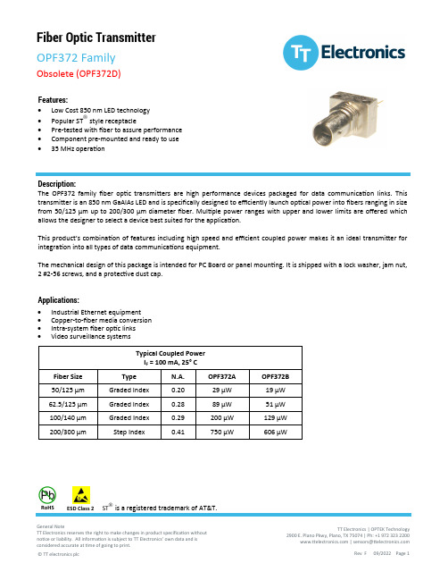
Fiber Optic Transmitter
OPF372 Family
Obsolete (OPF372D)
Cobra FRS237 2-Way Radio 说明书
2-WA Y RADIO MODEL Owner’s ManualBelt ClipWrist StrapIntroMain IconsSecondary IconsFRS237Product FeaturesOperationCustomer AssistanceWarrantyIntroOperationCustomerAssistanceWarrantySecondary Icons IntroductionIntroOperation Customer Assistance WarrantySecondary Icons IntroductionIntroOperation Customer AssistanceSecondary IconsCaring for Your microTALK ®Radio •Your microTALK ®radio will give you years of trouble-free service if cared for properly. Handle the radio gently. Keep the radio away from BatteriesTo Install or Replace Batteries:1. Remove belt clip by releasing belt clip latch and sliding clip up.2. Pull down on theremove the battery compartment cover.Backlit LCD Display CompartmentBattery DoorLatchBelt Wrist Strap ConnectorIntroOperationCustomer AssistanceWarrantyNoticeLock Button Backlit LCD Display Channel Up/Down Buttons Speaker/MicrophoneCall ButtonMode ButtonVolume Up/Down External Speaker/Microphone JackLight/MaxRange ButtonTalk ButtonOn/Off Power Button LockLowFeatures•Two-Way Radio With a range 14 Channels 38 Privacy Codes Insert BatteriesPull Down Lock LatchRemove Belt ClipOperationCustomer AssistanceWarrantyNoticeMain IconsSecondary IconsThe Basics to Get You Started Your microTALK ®radio is easy to use. To get started, simply:1. Press the Power button to turn On your radio.2. Press the Channel Up or Channel Down button to select a channel.Both radios must be tuned to the same channel to communicate.3. Press and hold the Talk button while speaking into the microphone.4. When finished talking, release the Talk button and listen for a response.Operation Customer AssistanceWarrantyMain Icons 38 Privacy CodesOperation WarrantyMain IconsIntroOperation Customer Assistance WarrantyNoticeSecondary IconsScrolling Through the Mode Function•By scrolling through the Mode function, you will be able to select or turn On preferred features of your microTALK ®radio. When scrolling throughthe Mode function, your radio features will be displayed in the same predetermined order:Channels•To Select a Channel:1. With the radio On, select any of the CTCSS Privacy Codes•CTCSS (Continuous Tone Coded Squelch System)is an advanced tone coding system allowing you to select one of 38 privacy codes to reduce IntroOperation Customer AssistanceWarrantyNoticeMain IconsSecondary IconsTurning On Your microTALK ®Radio •To Turn On Your Radio:1. Press and hold the Power button until you hear a series of audible tones indicating the radio is On.Your microTALK ®radio is now in Standby Mode ,ready to receive transmissions. The radio is always in Standby Mode except when the Talk ,Call or Mode buttons are pressed.Battery Low•When battery power is low, the Battery Low icon will blink. Your batteries should be replaced or recharged, if using rechargeable batteries.Auto Battery Save•Your microTALK ®radio has a unique circuit designed to extend battery life. If there are no transmissions within ten (10) seconds, the radio will automatically switch to Battery Save Mode and Power Saver icon will flash in the display.This will not affect the radio’s ability to receive incoming transmissions.2. With the microphone about five (5) centimeters (2 inches) from your mouth, speak in a normal voice.3. Release the Talk button when you are finished talking and listen for a response.You cannot receive incoming calls while pressing the Talk button.IntroOperationCustomer AssistanceWarranty NoticeSecondary IconsMode ButtonOn/Off PowerBattery Save ModeTalk ButtonChannel Button5cm (2 inches) From MouthIntroOperation Customer AssistanceWarranty NoticeSecondary IconsMode ButtonChannel ButtonAssistance Secondary IconsIntroOperationCustomerAssistanceWarrantyCall Button•To Alert Another Person That You Are Calling:1. Press and release the Call button.The other person will hear a two (2) second calltone. You cannot send or receive transmissions during the two (2) second call tone.main channels (1 through 14) or the privacy codes (00 through 38) within one (1) main channel.To Scan Main Channels:1. Press the Mode button until the Scan icon and the main channel number flashes on the display.2. Press the Channel Up or Channel Down button to begin scanning the main channels.3. The Scan icon will continue to be displayed when Scan is On. Your radio will continue to scan all main channels and stop if an incoming transmission is detected.Your radio will remain on that channel for ten (10) seconds. During this time, you can:a. Press and hold the Talk button and communicate with others. Your radio will remain on that channel and return to Standby Mode .b. Press the Channel Up or Channel Down button to resume scanning channels.c. Press the Mode button to proceed to privacy code scanning (see page 10 for further details).Intro Operation Customer AssistanceWarrantyNoticeSecondary IconsTo Select a Privacy Code:1. After selecting a channel, press the Mode button until the small numbers next to the channel number flash on the LCD.2. Press the Channel Up or Channel Down button to select a privacy code. You can hold the Up or Down button for fast advance.3. When your desired privacy code is displayed:a. Press the Mode button to enter the new setting and proceed to other functions.b. Press the Lock button to enter the new setting and return to Standby Mode .c. Do not press any buttons for 15 seconds to enter the new setting and return to Standby Mode .Listening for a Response•When You are Finished Talking:1. Release the Talk button to receive incoming transmissions. Your microTALK ®radio is always in Standby Mode while the Talk or Call buttons are not pressed.Volume•To Adjust the Volume:1. Press the Volume Up or Volume Down button.A double beep sound is used to indicate the minimum and maximum volume levels (L1 through L7).ListeningCall ButtonVolume Button Volume LevelPrivacy CodeModeButton Scanning ChannelsIntroOperation Customer AssistanceWarrantyNotice Secondary IconsIntroOperationCustomerAssistanceWarrantyNotice Secondary IconsIf you press the Talk button while scanning and not within ten (10) seconds of receiving a transmission you will transmit on the last channel you transmitted or received on.If you do not press any button within ten (10)seconds, your radio will automatically resume scanning main channels. To Scan Privacy Codes:1. While in Standby Mode ,press the Channel Up or Channel Down button to choose the main channel you wish to scan.2. Press the Mode button until the Scan icon and the privacy code number flashes on the display.3. Press the Channel Up or Channel Down button and your radio will begin scanning privacy codes within the main channel you selected.4. The Scan icon will continue to be displayed when Scan is On. Your radio will continue to scan privacy codes and stop an incoming transmission is detected.Your radio will remain on that channel and privacy code for ten (10)seconds. During this time, you can:a. Press and hold the Talk button to communicate with others. Your radio will remain on that channel and privacy code and return to Standby Mode .b. Press the Channel Up or Channel Down button to resume scanning privacy codes.c. Press the Mode button to proceed to other functions.If you press the Talk button while scanning and not within ten (10) seconds of receiving a transmission you will transmit on the last channel you transmitted or received on.If you do not press any button within ten (10)seconds, your radio will automatically resume scanning privacy codes.Channel ButtonMode ButtonSelect ChannelScan Privacy Codes10 Call T one Settings •You can choose between ten (10) different call tone settings to transmit a unique call alert. To Change a Call Tone Setting:1. Press the Mode button until the letter “C”and the current call tone number (1 through 10) is displayed. The current call tone will sound for one (1) second.Up or Channel Down 3.button to enter the newsetting and proceed to other functions.b. Press the Lock button to enter the new setting and return to Standby Mode .“Roger Beep” Confirmation T one•Your listener will hear an audible tone when you release the Talk button. This alerts the other party that you are finished talking and it is OK for them to speak. This feature can be turned On or Off.To Turn “Roger Beep” On or Off:When turning On your microTALK ®radio for the first time, “Roger Beep” will be On.1. Press the Mode button until the Roger Beep icon flashes. The current On or Off setting is displayed.2. Press the Channel Up or Channel Down button to select “Roger Beep” On or Off.3.a. Press the Mode button to enter the newsetting and proceed to other functions.b. Press the Lock button to enter the new setting and return to Standby Mode .The setting you select will be saved when you turn your radio Off and On again. When the “Roger Beep” is On, the “Roger Beep” icon will be displayed.Call Tone Setting Mode ButtonChannel ButtonRoger Beep OffMode ButtonChannel ButtonIntroOperation Customer AssistanceWarrantyNotice Secondary IconsDisplay Illumination •To Illuminate Your Display:1. Press and release the Light/Max Range button to illuminate the display for ten (10) seconds.Auto Squelch/Maximum Range•Your microTALK ®radio is equipped with Auto Squelch, which automatically shuts Off weak transmissions and unwanted noise due to terrain, conditions, or if you’ve reached your maximum range limit.You can temporarily turn Off Auto Squelch or turn On Maximum Range Extender, allowing all signals to be received and extending the maximum range of your radio.To Temporarily Turn Off Auto Squelch:1. Press the Light/Max Range button less than five (5) seconds.If you hear two (2) beeps, you have turned the Maximum Range Extender On (see below).To Turn Maximum Range Extender On:1. Press and hold the Light/Max Range button for at least five (5) seconds until you hear two (2) beeps which indicates the Maximum Range Extender is On.To Turn Maximum Range Extender Off:1. Press and release the Light/Max Range button or change channels.IntroOperationCustomer AssistanceWarrantyNoticeSecondary IconsLock ModeLock ButtonLight/Max RangeLight/Max RangeIntroSecondary IconsLock Function •The Lock function locks the Channel ,Mode ,and Power buttons to prevent accidental operation. To Turn the Lock On or Off:1. Press and hold the Lock button for two (2) seconds.A double beep sound is used to confirm Speaker/Microphone Jack •Reduced RangeReduced RangeMaximum RangeSpeaker/MicrophoneIntroOperationCustomerAssistanceWarrantyNotice Secondary Icons IntroOperationCustomer AssistanceWarrantyNoticeSecondary Icons2. Carrier Frequency Stability . . .±Hz 5003. Modulation Limiting . . . . . . . .KHz 2.54. Carrier Attack Time . . . . . . . . .mS 805. Audio Frequency Response@300 HZ . . . . . . . . . . . . . . . . .dB -12@2500 HZ ................dB +66. Audio Distortion . . . . . . . . . . . .% 37. Hum Noise . . . . . . . . . . . . . . . .dB308. Transient Frequency Behaviora) TX On . . . . . . . . . . . . . . . . .mS 30b) TX Off . . . . . . . . . . . . . . . . .mS5A.FRS Frequency AllocationA =Channel No.For14 Channel FRS Models B =Frequency in MHz C =Power in Watts4462.6375 0.55462.6625 0.56462.6875 0.57462.7125 0.58467.5625 0.5 B.Receiver1. SensitivityFor 12 DB SINAD . . . . . . . . . .dBm -121For Call Signal Detection . . . .dBm -1212. Max. Audio Output@10% THD . . . . . . . . . . . . . . .mW 2003. Max. S/N Ratio@1mV RF Input . . . . . . . . . . .dB 504. Squelcha) Sensitivity . . . . . . . . . . . . . .dBm -121b) Attack Time . . . . . . . . . . . . .mS 150c) Closing Time . . . . . . . . . . . .mS 2005. Audio Frequency Response@300 HZ . . . . . . . . . . . . . . . . .dB -3@2500 HZ . . . . . . . . . . . . . . . .dB -106. Signal Displacement BW . . .+/-KHZ 57. Adjacent Channel Rejection . . .dB608. Intermodulation Rejection . . . .dB 659. Spurious Response Rejection .dB551. Battery Life (5:5:90 RATIO)With Alkaline Batteries . . . . . . .HR 242. Battery Operating Range . . . . . .V 4.2 - 6.0N o m i n a lU n i toAssistanceIf you have any questions about operation or installing your new Cobra ®product,or if you are missing parts…Please call Cobra ®first! DO NOT RETURN THIS PRODUCT TO THE STORE! See customer service on page 2.Product ServiceFor Products Purchased in CanadaFor out of warranty service, ship prepaid this product to: AVS Technologies Inc., 2100 TransCanadaHwy S., Montreal, Quebec, H9P 2N4. We reserve the right to repair or replace the radio with anequivalent product. Please include the following information: Date of Purchase, Model Number, Dealer Purchased From, Dealer Address, Dealer Phone Number.For Products Purchased in the U.S.A.first before sending your radio. Cobra or carbon of a sales receipt. If you send the original receipt, it cannot be returned; 2) Send the entireproduct; 3) Enclose a description of what is happening with the radio. Include a typed or clearlyprinted name and address of where the radio is to be returned; 4) Pack radio securely to prevent damage in transit. If possible, use the original packing material; 5) Ship prepaid and insured by way of a traceable carrier such as United Parcel Service (UPS) or First Class Mail to avoid loss in transit to Cobra Factory Service ,Cobra Electronics Corporation, 6500 West Cortland Street, Chicago,Illinois 60707 USA; 6) If the radio is in warranty,upon receipt of your radio it will either be repaired or exchanged depending on the model. Please allow approximately 3 – 4 weeks before contacting Cobra for status. If the radio is out of warranty,a letter will automatically be sent informing you of the repair Your new Cobra FRS is covered by a one (1) year replacement warranty. If any manufacturing defect becomes apparent in this product within one (1) year from the original date of purchase, it will bereplaced. Please return the FRS radio to your dealer with original or copy of dated proof of purchase.This warranty does not cover damages due to careless handling, negligence, accident, abuse or failure to follow operating instructions. Alteration of this product or defacing of the serial number cancels all obligations of this warranty. This warranty gives you specified legal rights. Additional warranty rights may be provided by law in some areas.Limited 1-Year Warranty For Products Purchased in the U.S.A.Cobra Electronics Corporation warrants that its Cobra FRS radios, and the component parts thereof, will be free of defects in workmanship and materials for a period of one (1) year from the date of first consumer purchase. This warranty may be enforced by the first consumer purchaser,provided that the product is utilized within the U.S.A. Cobra will, without charge, repair or replace,at its option, defective FRS radios, products or component parts upon delivery to the Cobra Factory Service department,accompanied by proof of the date of first consumer purchase, such as a duplicated copy of a sales receipt.You must pay any initial shipping charges required to ship the product for warranty service, but the return charges will be at Cobra ’s expense, if the product is repaired or replaced under warranty. This warranty gives you specific legal rights, and you may also have other rights which may vary from state to state.Exclusions: This limited warranty does not apply: 1) To any product damaged by accident; 2) In the event of misuse or abuse of the product or as a result of unauthorized alterations or repairs; 3) If the serial number has been altered, defaced, or removed; 4) If the owner of the product resides outside the U.S.A.All implied warranties, including warranties of merchantability and fitness for a particular purpose are limited in duration to the length of this warranty. Cobra shall not be liable for any incidental, consequential or other damages; including, without limitation, damages resulting from loss of use or cost of installation.Some states do not allow limitations on how long an implied warranty lasts and/or do not allow the exclusion or limitation of incidental or consequential damages, so the above limitations may not apply to you.For products purchased outside the U.S.A.,please contact your local dealer for warranty information.IntroOperation Customer Assistance Warranty Main IconsSecondary IconsAddress (No P .O.Boxes)City State/ProvinceZipCountryT elephoneCredit Card Number T ype:ÌVisa ÌMastercard ÌDiscover Exp.Date**Quebec residents only.Ordering From Canada to 5:00 p.m. EST,Monday through Friday.Make check or money order payable to:AVS Technologies, Inc.2100 Trans Canada Highway South Montreal, Quebec H9P 2N4Please allow 4-6 weeks for delivery in Canada.Prices subject to change without notice.Michigan add 6%; Illinois add 8.75%.Call 773-889-3087 for pricing or visit .For credit card orders,complete and return this order form to fax number 773-622-2269. Or call 773-889-3087(Press 1 from the main menu) 8:00 a.m. to 6:00 p.m. CT, Monday through Friday.Make check or money order payable to: Cobra Electronics, Attn: Accessories Dept.6500 West Cortland Street Chicago, IL 60707 USATo order online,please visit our website:.Please allow 2-3 weeks for delivery in the U.S.Prices subject to change without notice.IntroOperation Customer AssistanceWarranty Secondary Icons。
USB 总线接口芯片CH372

CH372中文手册(一)1USB 总线接口芯片CH372中文手册版本:3D 1、概述CH372是一个USB 总线的通用设备接口芯片,是CH371的升级产品,是CH375芯片的功能简化版。
在本地端,CH372具有8位数据总线和读、写、片选控制线以及中断输出,可以方便地挂接到单片机/DSP/MCU/MPU等控制器的系统总线上;在计算机系统中,CH372的配套软件提供了简洁易用的操作接口,与本地端的单片机通讯就如同读写文件。
CH372内置了USB 通讯中的底层协议,具有省事的内置固件模式和灵活的外置固件模式。
在内置固件模式下,CH372自动处理默认端点0的所有事务,本地端单片机只要负责数据交换,所以单片机程序非常简洁。
在外置固件模式下,由外部单片机根据需要自行处理各种USB 请求,从而可以实现符合各种USB 类规范的设备。
2、特点● 全速USB 设备接口,兼容USB V2.0,即插即用,外围元器件只需要晶体和电容。
● 提供一对主端点和一对辅助端点,支持控制传输、批量传输、中断传输。
● 具有省事的内置固件模式和灵活的外部固件模式。
● 内置固件模式下屏蔽了相关的USB 协议,自动完成标准的USB 枚举配置过程,完全不需要本地端控制器作任何处理,简化了单片机的固件编程。
● 通用Windows 驱动程序提供设备级接口,通过DLL 提供API 应用层接口。
● 产品制造商可以自定义厂商标识(Vendor ID)和产品标识(Product ID)。
● 通用的本地8位数据总线,4线控制:读选通、写选通、片选输入、中断输出。
● 主端点上传下传缓冲区各64字节,辅助端点上传下传缓冲区各8字节。
● 支持5V 电源电压和3.3V 电源电压,支持低功耗模式。
● CH372芯片是CH375芯片的功能简化版,CH372在CH375基础上减少了USB 主机方式和串口通讯方式等功能,所以硬件成本更低,但是其它功能完全兼容CH375,可以直接使用CH375的WDM 驱动程序和DLL 动态链接库。
- 1、下载文档前请自行甄别文档内容的完整性,平台不提供额外的编辑、内容补充、找答案等附加服务。
- 2、"仅部分预览"的文档,不可在线预览部分如存在完整性等问题,可反馈申请退款(可完整预览的文档不适用该条件!)。
- 3、如文档侵犯您的权益,请联系客服反馈,我们会尽快为您处理(人工客服工作时间:9:00-18:30)。
接线端子板TB372-R
1基本说明
TB372-R端子板为8路端子板,可供单卡或2块互冗余FW372(或FW373)使用,提供接线通道,实现8路电流信号的输出处理。
2使用说明
2.1端子板外观图
TB 372-R端子板结构外形如下图 2-1所示:
图 2-1 TB372-R端子板结构外形图
2.2接插件说明
TB372-R端子板接插件说明如表 2-1所示:
表 2-1 TB372-R端子板接插件说明
标号说明
J1 接线端子
J2 第一块卡数据连线插座
J3 第二块卡数据连线插座
2.3端子定义及接线
TB372-R接线说明如表 2-2所示。
表 2-2 TB372-R接线端子说明
定义端子号
定义
CH1+ 12CH1-
CH2+ 34CH2-
CH3+ 56CH3-
CH4+ 78CH4-
NC 910NC
CH5+ 1112CH5-
CH6+ 1314CH6-
CH7+ 1516CH7-
CH8+ 1718CH8-
NC 1920NC
NC 2122NC
NC 2324NC
NC 2526NC
NC 2728NC
NC 2930NC
NC 3132NC
NC 3334NC
NC 3536NC
NC 3738NC
NC 3940NC
NC 4142NC
NC 4344NC
NC 4546NC
NC 4748NC
保护地端子4950保护地端子
z“CH1+”表示第1路信号输出正端,“CH1-”表示第1路信号输出负端,数字表示通道号,依次类推。
z NC表示接线端子不接线。
z该端子板无须供电,属无电源端口。
3资料版本说明
表 3-1版本升级更改一览表
资料版本号输出时间更改说明TB372-R使用手册(V1.0)。
