TIM7785-12UL中文资料
浓盐水电子有限公司-太阳能转换器产品说明书

TPS_GCN_F_09.20E– Rev. 1 2012-10-29 Client: Huawei Technologies Co., LtdAdministration Building Headquarters of Huawei Technologies Co., Ltd.,Bantian, Longgang District, 518129 Shenzhen, PEOPLE'S REPUBLIC OFCHINAManufacturing place: Huawei Technologies Co., LtdAdministration Building Headquarters of Huawei Technologies Co., Ltd.,Bantian, Longgang District, 518129 Shenzhen, PEOPLE'S REPUBLIC OFCHINATest subject: Product: SOLAR INVERTERType:SUN2000-36KTL, SUN2000-33KTL-ATest specification: VDE-AR-N 4105:2011DIN VDE V 0124-100(VDE V 0124-100):2012DIN VDE 0126-1-1 (VDE V 0126-1-1):2013Purpose of examination: ∙Annex G.2, G.3, F3 and F4 from standard VDE-AR-N 4105∙TÜV SÜD certification mark specificationsTest result: The test results show that the presented product is in compliance with the specified requirements.Technical Report No. <70.409.16.086.03-02>G.2 Certificate of conformity for power generation unitsF.3 Requirements for the test report for power generation unitsG.3 Certificate of conformity of the network and system protectionF.4 Requirements for the test report for the NS protectionDated <2017-05-02>This technical report may only be quoted in full. Any use for advertising purposes must be granted in writing. This report is the result of a single examination of the object in question and is not generally applicable evaluation of the quality of other products in regular production.TPS_GCN_F_09.20E– Rev. 1 2012-10-29 1 Description of the test subject1.1 FunctionThese devices are transformer-less grid-connected PV inverters which converts direct current optimized by photovoltaic DC conditioner to alternating current, and they are in-tended to be connected in parallel with the public grid directly.They are intended for professional incorporation into PV system, and they are assessed on a component test basis.Firmware version: V200R0021.2 Consideration of the foreseeable misuseNot applicableCovered through the applied standardCovered by the following commentCovered by attached risk analysis1.3 Technical DataModel : SUN2000-36KTL, SUN2000-33KTL-APV input :d.c. Max. Input Voltage: 1100 Vd.c.d.c. MPP Range: 200-1000 Vd.c.d.c. Max. Input Current: 22 A /22 A /22 A /22 AIsc PV: 30 A /30 A /30 A /30 AAC output :a.c. Output Nominal Voltage: 3/N/PE~, 400Va.c. Nominal Operating Frequency: 50 Hza.c. Output Max. Current: 57,8 A (SUN2000-36KTL),48 A (SUN2000-33KTL-A)a.c. Output Rated Power: 36 kVA (SUN2000-36KTL),30 kVA (SUN2000-33KTL-A)a.c. Output Max. Active Power: 40 kW (SUN2000-36KTL), 33 kW (SUN2000-33KTL-A)a.c. Output Max. Apparent Power: 40 kVA (SUN2000-36KTL), 33 kVA (SUN2000-33KTL-A)Protection Class : IIngress protection : IP65Construction : Fixed equipmentSupply connection : Non-detachable power supply cableWeight : 55kg(SUN2000-36KTL)/60kg(SUN2000-33KTL-A)TPS_GCN_F_09.20E– Rev. 1 2012-10-29 2 Order2.1 Date of Purchase Order, Customer’s Reference2017.04.05, 7482130808/20002.2 Receipt of Test Sample, Location2016.04.15, 2017.04.15Nanjing CQC - Trusted Testing Technology Co., Ltd.No.99,Wenlan Road, Xianlin University Zone, Xianlin Street, Qixia District, NanJing, China2.3 Date of Testing2016-04-15 – 2016-05-04(original), 2017-04-15 – 2017-04-20(revised)2.4 Location of TestingNanjing CQC - Trusted Testing Technology Co., Ltd.No.99,Wenlan Road, Xianlin University Zone, Xianlin Street, Qixia District, NanJing, China2.5 Points of Non-compliance or Exceptions of the Test ProcedureNoneTPS_GCN_F_09.20E– Rev. 1 2012-10-29 3 Test Results3.1 Positive Test Results (as attachment of type D certificate)G.2 Certificate of conformity for power generation unitsCertificate of conformityPower generation unit No. 70.409.16.086.03-02ManufacturerHuawei Technologies Co., Ltd.Administration Building Headquarters of HuaweiTechnologies Co., Ltd., Bantian, Longgang District, 518129Shenzhen, PEOPLE'S REPUBLIC OF CHINA Type power generation unit SOLAR INVERTERModel SUN2000-36KTL, SUN2000-33KTL-AAssessment valuesMax. active power P Emax40048 W (SUN2000-36KTL)30322 W (SUN2000-33KTL-A)Max. apparent power S Emax40057 VA (SUN2000-36KTL)33127 VA (SUN2000-33KTL-A)Rated voltage 3/N/PE~, 400V Network connection rulesVDE-AR-N 4105 “Power generation systems connec tedto the low-voltage network”Technical minimum requirements for connection andparallel operation of power generation systems connectedto the low-voltage networkFirmware version V200R002Period of measurementFrom 2016-04-15 to 2016-05-04(original) and From 2017-04-15 to 2017-04-20(revised)The above mentioned power generation unit meets the requirements of VDE-AR-N 4105.Description of the structure and schematic set-up of the generating unit. (including single faultcheck)The generating unit integrated EMC filter on both PV and AC side converts direct current optimized byphotovoltaic DC conditioner to alternating current and it is intended to be connected in parallel with the low-voltage mains to supply common load. The generating unit has no electrical isolation between DC inputand AC output. The output is switched off by the failsafe inverter bridge and two relays in series. This al-lows a safe separation from generating unit to the network, also in case of failure. Refer to below illustra-tion.TPS_GCN_F_09.20E– Rev. 1 2012-10-29SUN2000-36KTL and SUN2000-33KTL-ATPS_GCN_F_09.20E– Rev. 1 2012-10-29 F.3 Requirements for the test report for power generation unitsExtract from test report for unit certificate“Determination of electrical properties”No. 70.409.16.086.03-02Type of systemGrid-connectedinverter for PVsystemManufacturer’s dataGeneration unitmanufacturerHuaweiTechnologies Co.,Ltd.Address:AdministrationBuildingHeadquarters ofHuaweiTechnologies Co.,Ltd., Bantian,Longgang District,518129 Shenzhen,PEOPLE'SREPUBLIC OFCHINAType of system:Grid-connected inverter for PVsystemActive power(nominal powerat referenceconditions):36kW (SUN2000-36KTL)30kW (SUN2000-33KTL-A)Rated voltage: 3/N/PE~, 400VPeriod ofmeasurement:From 2016-04-15 to 2016-05-04(original) and From 2017-04-15 to 2017-04-20(revised)Active power P Emax40048 W (SUN2000-36KTL), 30322 W (SUN2000-33KTL-A)(Assessment values)Reactive power reference(@0,91Un) – SUN2000-36KTLActive powerP/P Emax[%]10 20 30 40 50 60 70 80 90 100Max. possiblecosφunder-excited0,8020 0,8016 0,8014 0,8011 0,8009 0,8008 0,8007 0,8781* 0,9930* N/A**Max. possiblecosφover-excited0,7950 0,7975 0,7982 0,7987 0,7990 0,7991 0,7993 0,8695* 0,9880* N/A**The max. current is limited by software to 57,8 A, the apparent power and active power are limited accordingly when test at fixed grid voltage(0,91Un).S limited=P limited=57,8 x 209,3 x 3 ≈ 36293 W/VA“*”: Due to apparent power is limited to S limited, the active power is reduced accordingly when adjust cos φ. It is therefore not achieved to default cos φ at points 80% and 90% P/P Emax. The max. possible c os φ is recorded accordingly.“**”: The P Emax can not reached when test at 0,91Un.Reactive power reference (@Un) – SUN2000-36KTLActive powerP/P Emax[%]10 20 30 40 50 60 70 80 90 100Max. possiblecosφunder-excited0,8019 0,8015 0,8011 0,8010 0,8007 0,8007 0,8007 0,8006 0,9015* 0,9998*TPS_GCN_F_09.20E– Rev. 1 2012-10-29 Max. possiblecosφover-excited0,7951 0,7974 0,7982 0,7985 0,7991 0,7993 0,7993 0,7994 0,8988* 0,9998*“*”: Due to apparent power is limited to S Emax, the active power is reduced accordingly when adjust cos φ. It is therefore not achieved to default cos φ at points 90% and 100% P/P Emax. The max. possible cos φ is recorded accordingly.Reactive power reference (@1,09Un) – SUN2000-36KTLActive powerP/P Emax[%]10 20 30 40 50 60 70 80 90 100Max. possiblecosφunder-excited0,8023 0,8017 0,8012 0,8011 0,8008 0,8007 0,8007 0,8006 0,8966* 0,9998*Max. possiblecosφover-excited0,7954 0,7977 0,7984 0,7987 0,7990 0,7991 0,7994 0,7996 0,8987* 0,9998*“*”: Due to apparent power is limited to S Emax, the active power is red uced accordingly when adjust cos φ. It is therefore not achieved to default cos φ at points 90% and 100% P/P Emax. The max. possible cos φ is recorded accordingly.Reactive power reference (@Un) – SUN2000-33KTL-AActive powerP/P Emax [%]10 20 30 40 50 60 70 80 90 100Max. possiblecosφunder-excited- 0,8006 0,8010 0,8011 0,8012 0,8010 0,8010 0,8010 0,8012 0,9082*Max. possiblecosφover-excited- 0,7976 0,7977 0,7978 0,7980 0,7979 0,7973 0,7979 0,7982 0,9083*“*”: Due to apparent power is limited to S Emax, the active power is reduced accordingly when adjust cos φ. It is therefore not achieved to default cos φ at points 100% P/P Emax. The max. possible cos φ is recorded accordingly.Reactive power reference (@1,09Un) – SUN2000-33KTL-AActive powerP/P Emax[%]10 20 30 40 50 60 70 80 90 100Max. possiblecosφunder-excited- 0,8007 0,8010 0,8011 0,8012 0,8014 0,8011 0,8012 0,8008 0,9072*Max. possiblecosφover-excited- 0,7980 0,7977 0,7978 0,7980 0,7981 0,7981 0,7982 0,7981 0,9067*“*”: Due to apparent power is limited to S Emax, the active power is reduced accordingly when adjust cos φ. It is therefore not achieved to default cos φ at points 100% P/P Emax. The max. possible cos φ is recorded accordingly.TPS_GCN_F_09.20E– Rev. 1 2012-10-29 Compliance of required displacement factor cosφ– SUN2000-36KTLDefaultinsystemcontrol0,900ov 0,920ov0,940ov0,960ov0,980ov1,000 0,980un0,960un0,940un0,920un0,900unMeasuredvalueat PGUterminals0,8990 0,9198 0,9398 0,9598 0,9796 0,9998 0,9800 0,9600 0,9402 0,9202 0,9003Switching actions – SUN2000-36KTLMaking operation without default (of primary energy carrier) k i0,127Worst case at switch over of generator sections* k i-Making operation at reference conditions (of primary energycarrier)k i1,001Breaking operation at nominal power k i1,001Worst-case value of all switching operations k imax1,001Remark: “*” Not applicable for PV systemFlicker –SUN2000-36KTLAngle of network impedance ψk:32°1) 50°70°85°Coefficient of system flicker cψ: 2,38 - - -Remark: 1) R A = 0,24 Ω; X A = j 0,15 Ω at 50 Hz network impedance used for most unfavorable condition which is approximately 32° flicker angle.Reactive power transfer function – Standard-cosφ-(P)-characteristic – SUN2000-36KTLActive powerP/P n [%]10 20 30 40 50 60 70 80 90 100 cosφ0,9949 0,9987 0,9993 0,9995 0,9996 0,9799 0,9595 0,9398 0,9196 0,9999 Conform to Standard- cosφ-(P)-characteristicRemark:“*”:The maximum apparent power of the inverter is limited to SEmax. If setting cos φ≠1, the maximum active power is reduced accordingly. The active power 100% P/PEmax is therefore only achieved when cos φ = 1.Starting with a power of 0,2 P Emax, the characteristic curve shall be adhered to according to VDE AR-N 4105: 2011.TPS_GCN_F_09.20E– Rev. 1 2012-10-29 Harmonics – SUN2000-36KTLActivepowerP/Pn[%]0 10 20 30 40 50 60 70 80 90 100OrdinalnumberI [%] I [%] I [%] I [%] I [%] I [%] I [%] I [%] I [%] I [%] I [%]2 - 0,214 0,265 0,302 0,347 0,395 0,428 0,464 0,506 0,544 0,5633 - 0,103 0,102 0,082 0,070 0,065 0,061 0,069 0,080 0,095 0,1014 - 0,075 0,090 0,084 0,074 0,065 0,056 0,047 0,043 0,051 0,0525 - 0,149 0,177 0,274 0,312 0,367 0,374 0,407 0,394 0,409 0,3896 - 0,026 0,037 0,032 0,032 0,032 0,030 0,030 0,032 0,039 0,0717 - 0,291 0,237 0,215 0,171 0,196 0,199 0,271 0,302 0,350 0,3428 - 0,021 0,021 0,030 0,028 0,030 0,032 0,033 0,036 0,037 0,0579 - 0,035 0,044 0,048 0,051 0,050 0,055 0,057 0,072 0,072 0,08310 - 0,021 0,017 0,029 0,029 0,026 0,028 0,026 0,031 0,025 0,02011 - 0,216 0,192 0,333 0,329 0,350 0,340 0,351 0,384 0,378 0,38212 - 0,018 0,019 0,030 0,029 0,026 0,028 0,027 0,036 0,035 0,02913 - 0,250 0,167 0,285 0,306 0,307 0,348 0,341 0,392 0,398 0,40414 - 0,015 0,016 0,020 0,019 0,019 0,019 0,022 0,026 0,028 0,02715 - 0,039 0,036 0,032 0,033 0,036 0,036 0,034 0,033 0,037 0,03716 - 0,015 0,014 0,018 0,018 0,019 0,020 0,023 0,030 0,033 0,03417 - 0,115 0,145 0,181 0,199 0,209 0,220 0,256 0,277 0,289 0,31118 - 0,014 0,015 0,023 0,021 0,021 0,021 0,028 0,039 0,041 0,03619 - 0,086 0,136 0,158 0,161 0,178 0,186 0,207 0,245 0,255 0,26020 - 0,013 0,013 0,020 0,016 0,015 0,016 0,018 0,026 0,028 0,02421 - 0,023 0,024 0,039 0,032 0,022 0,026 0,024 0,030 0,032 0,03422 - 0,012 0,016 0,022 0,022 0,014 0,015 0,018 0,024 0,026 0,02523 - 0,069 0,096 0,125 0,115 0,125 0,139 0,160 0,176 0,207 0,22224 - 0,015 0,020 0,024 0,027 0,021 0,038 0,024 0,031 0,035 0,03525 - 0,045 0,076 0,114 0,097 0,109 0,118 0,135 0,148 0,175 0,19626 - 0,015 0,018 0,014 0,016 0,026 0,038 0,033 0,023 0,027 0,02827 - 0,018 0,021 0,017 0,020 0,037 0,033 0,034 0,022 0,027 0,02828 - 0,013 0,017 0,013 0,012 0,021 0,016 0,031 0,031 0,022 0,02229 - 0,017 0,049 0,082 0,062 0,083 0,084 0,104 0,110 0,132 0,15430 - 0,012 0,017 0,016 0,013 0,021 0,020 0,018 0,045 0,029 0,03131 - 0,021 0,044 0,070 0,048 0,068 0,072 0,080 0,081 0,114 0,13232 - 0,012 0,013 0,014 0,011 0,014 0,020 0,016 0,031 0,025 0,03433 - 0,018 0,014 0,013 0,016 0,014 0,021 0,018 0,019 0,031 0,03934 - 0,014 0,011 0,015 0,014 0,012 0,020 0,018 0,019 0,022 0,03335 - 0,026 0,026 0,043 0,038 0,053 0,061 0,062 0,053 0,079 0,10636 - 0,014 0,011 0,013 0,016 0,015 0,019 0,020 0,017 0,022 0,03637 - 0,025 0,015 0,033 0,034 0,041 0,055 0,051 0,040 0,068 0,09138 - 0,013 0,011 0,012 0,013 0,013 0,016 0,019 0,015 0,019 0,02739 - 0,018 0,016 0,016 0,016 0,015 0,018 0,023 0,022 0,023 0,02640 - 0,013 0,011 0,015 0,013 0,012 0,015 0,020 0,021 0,019 0,020TPS_GCN_F_09.20E– Rev. 1 2012-10-29 Subharmonics – SUN2000-36KTLActivepowerP/Pn[%]0 10 20 30 40 50 60 70 80 90 100Frequency[Hz]I [%] I [%] I [%] I [%] I [%] I [%] I [%] I [%] I [%] I [%] I [%]75 - 0,045 0,047 0,049 0,051 0,052 0,054 0,056 0,059 0,060 0,061125 - 0,035 0,036 0,035 0,038 0,036 0,036 0,036 0,037 0,036 0,035 175 - 0,030 0,029 0,028 0,029 0,029 0,028 0,028 0,030 0,029 0,027 225 - 0,027 0,025 0,025 0,026 0,026 0,027 0,027 0,030 0,027 0,026 275 - 0,025 0,024 0,024 0,025 0,025 0,025 0,026 0,028 0,026 0,025 325 - 0,024 0,023 0,023 0,024 0,024 0,025 0,025 0,027 0,026 0,025 375 - 0,023 0,022 0,023 0,023 0,024 0,025 0,025 0,027 0,026 0,025 425 - 0,023 0,022 0,022 0,023 0,024 0,025 0,025 0,027 0,026 0,024 475 - 0,022 0,021 0,022 0,022 0,023 0,024 0,024 0,026 0,026 0,024 525 - 0,022 0,020 0,021 0,022 0,022 0,023 0,024 0,027 0,026 0,024 575 - 0,021 0,019 0,020 0,021 0,022 0,023 0,024 0,026 0,026 0,024 625 - 0,021 0,019 0,020 0,020 0,022 0,023 0,024 0,025 0,027 0,025 675 - 0,020 0,018 0,019 0,020 0,022 0,023 0,024 0,025 0,027 0,025 725 - 0,022 0,022 0,022 0,024 0,025 0,027 0,028 0,030 0,031 0,028 775 - 0,020 0,020 0,021 0,022 0,024 0,025 0,026 0,027 0,030 0,029 825 - 0,021 0,021 0,021 0,022 0,024 0,026 0,028 0,030 0,032 0,028 875 - 0,017 0,016 0,017 0,018 0,019 0,021 0,023 0,024 0,029 0,026 925 - 0,016 0,016 0,017 0,018 0,019 0,021 0,023 0,024 0,030 0,025 975 - 0,016 0,016 0,019 0,018 0,019 0,021 0,023 0,024 0,030 0,026 1025 - 0,017 0,019 0,026 0,021 0,019 0,021 0,022 0,029 0,034 0,026 1075 - 0,016 0,022 0,036 0,039 0,018 0,020 0,022 0,027 0,028 0,026 1125 - 0,016 0,021 0,034 0,035 0,018 0,020 0,022 0,032 0,031 0,026 1175 - 0,018 0,022 0,041 0,049 0,022 0,024 0,024 0,027 0,025 0,027 1225 - 0,020 0,024 0,024 0,032 0,030 0,049 0,025 0,026 0,025 0,027 1275 - 0,021 0,022 0,023 0,028 0,036 0,036 0,045 0,023 0,025 0,027 1325 - 0,020 0,026 0,015 0,017 0,049 0,049 0,049 0,022 0,026 0,027 1375 - 0,017 0,026 0,015 0,016 0,034 0,031 0,063 0,025 0,025 0,028 1425 - 0,018 0,025 0,015 0,016 0,037 0,022 0,047 0,047 0,025 0,028 1475 - 0,017 0,024 0,014 0,015 0,022 0,023 0,043 0,046 0,025 0,027 1525 - 0,017 0,023 0,014 0,015 0,021 0,025 0,021 0,051 0,107 0,029 1575 - 0,018 0,019 0,014 0,015 0,021 0,028 0,022 0,044 0,028 0,043 1625 - 0,018 0,018 0,022 0,016 0,018 0,029 0,022 0,025 0,108 0,041 1675 - 0,021 0,015 0,015 0,018 0,017 0,028 0,024 0,022 0,026 0,053 1725 - 0,021 0,016 0,021 0,019 0,015 0,027 0,026 0,022 0,024 0,049 1775 - 0,020 0,016 0,014 0,021 0,015 0,021 0,027 0,022 0,024 0,046 1825 - 0,020 0,016 0,013 0,019 0,016 0,021 0,031 0,023 0,025 0,042 1875 - 0,021 0,016 0,013 0,019 0,017 0,023 0,028 0,022 0,024 0,037 1925 - 0,020 0,015 0,014 0,018 0,018 0,022 0,029 0,023 0,024 0,033 1975 - 0,020 0,016 0,016 0,017 0,019 0,023 0,030 0,025 0,024 0,029TPS_GCN_F_09.20E– Rev. 1 2012-10-29Higher frequencies – SUN2000-36KTLActivepowerP/Pn[%]0 10 20 30 40 50 60 70 80 90 100Frequency[kHz]I [%] I [%] I [%] I [%] I [%] I [%] I [%] I [%] I [%] I [%] I [%]2.1 - 0,064 0,043 0,056 0,058 0,063 0,079 0,089 0,095 0,092 0,1062.3 - 0,066 0,047 0,055 0,050 0,046 0,056 0,063 0,073 0,088 0,0742.5 - 0,070 0,047 0,055 0,047 0,044 0,054 0,059 0,062 0,072 0,0742.7 - 0,084 0,058 0,066 0,053 0,049 0,060 0,075 0,073 0,072 0,0832.9 - 0,067 0,041 0,047 0,041 0,037 0,046 0,050 0,053 0,065 0,0643.1 - 0,059 0,040 0,050 0,040 0,033 0,037 0,043 0,050 0,060 0,0503.3 - 0,052 0,037 0,050 0,040 0,032 0,035 0,043 0,050 0,055 0,0563.5 - 0,045 0,037 0,038 0,037 0,031 0,035 0,040 0,036 0,041 0,0523.7 - 0,041 0,037 0,038 0,035 0,029 0,035 0,034 0,033 0,043 0,0503.9 - 0,030 0,041 0,035 0,030 0,030 0,031 0,037 0,044 0,041 0,0424.1 - 0,029 0,035 0,033 0,031 0,031 0,038 0,040 0,029 0,031 0,0334.3 - 0,025 0,027 0,032 0,032 0,026 0,028 0,028 0,028 0,029 0,0294.5 - 0,025 0,027 0,028 0,027 0,025 0,027 0,027 0,026 0,028 0,0294.7 - 0,024 0,025 0,025 0,026 0,025 0,025 0,026 0,026 0,027 0,0274.9 - 0,024 0,025 0,025 0,026 0,025 0,025 0,025 0,025 0,026 0,0275.1 - 0,024 0,024 0,024 0,026 0,025 0,026 0,027 0,028 0,029 0,0305.3 - 0,024 0,024 0,024 0,025 0,024 0,025 0,025 0,025 0,026 0,0285.5 - 0,024 0,024 0,024 0,025 0,024 0,025 0,025 0,025 0,025 0,0255.7 - 0,024 0,024 0,024 0,025 0,025 0,026 0,026 0,026 0,027 0,0285.9 - 0,024 0,024 0,024 0,024 0,024 0,025 0,024 0,025 0,025 0,0256.1 - 0,024 0,024 0,024 0,024 0,025 0,025 0,025 0,025 0,025 0,0256.3 - 0,024 0,024 0,025 0,025 0,026 0,025 0,025 0,025 0,026 0,0266.5 - 0,024 0,024 0,025 0,025 0,026 0,025 0,026 0,026 0,026 0,0266.7 - 0,024 0,024 0,024 0,024 0,025 0,025 0,025 0,025 0,025 0,0256.9 - 0,024 0,024 0,024 0,024 0,025 0,025 0,025 0,024 0,025 0,0257.1 - 0,024 0,024 0,025 0,025 0,025 0,025 0,025 0,025 0,025 0,0257.3 - 0,024 0,024 0,025 0,025 0,025 0,025 0,025 0,025 0,025 0,0257.5 - 0,024 0,024 0,024 0,024 0,024 0,025 0,024 0,024 0,024 0,0247.7 - 0,024 0,024 0,024 0,024 0,024 0,025 0,024 0,024 0,024 0,0247.9 - 0,024 0,024 0,024 0,024 0,024 0,024 0,024 0,024 0,024 0,0248.1 - 0,024 0,024 0,024 0,024 0,024 0,025 0,024 0,024 0,024 0,0248.3 - 0,024 0,024 0,024 0,024 0,024 0,024 0,024 0,024 0,024 0,0248.5 - 0,024 0,024 0,024 0,024 0,024 0,024 0,024 0,024 0,024 0,0248.7 - 0,024 0,024 0,024 0,024 0,025 0,024 0,025 0,024 0,025 0,0258.9 - 0,024 0,024 0,024 0,024 0,025 0,024 0,025 0,025 0,025 0,025 Remark:The harmonic values are maximum values from all phases.TPS_GCN_F_09.20E– Rev. 1 2012-10-29 Harmonics – SUN2000-33KTL-AActivepowerP/Pn[%]0 10 20 30 40 50 60 70 80 90 100OrdinalnumberI [%] I [%] I [%] I [%] I [%] I [%] I [%] I [%] I [%] I [%] I [%]2 - 0,141 0,116 0,118 0,105 0,111 0,115 0,121 0,113 0,113 0,1373 - 0,183 0,193 0,227 0,207 0,193 0,195 0,188 0,196 0,203 0,2014 - 0,159 0,122 0,144 0,134 0,120 0,119 0,116 0,118 0,119 0,1225 - 0,789 0,973 0,563 0,435 0,418 0,471 0,502 0,553 0,593 0,6176 - 0,044 0,033 0,043 0,089 0,031 0,032 0,029 0,030 0,029 0,0317 - 0,409 0,903 0,805 0,713 0,548 0,439 0,351 0,314 0,297 0,3098 - 0,076 0,078 0,083 0,112 0,115 0,094 0,095 0,099 0,102 0,1419 - 0,051 0,056 0,084 0,092 0,102 0,099 0,063 0,062 0,059 0,08910 - 0,080 0,098 0,103 0,111 0,127 0,141 0,103 0,102 0,100 0,14111 - 0,428 0,219 0,111 0,381 0,512 0,569 0,593 0,594 0,618 0,61212 - 0,022 0,024 0,023 0,036 0,026 0,083 0,035 0,041 0,036 0,08913 - 0,308 0,223 0,106 0,270 0,402 0,465 0,510 0,522 0,553 0,55514 - 0,039 0,044 0,043 0,053 0,053 0,051 0,056 0,064 0,062 0,06515 - 0,031 0,041 0,036 0,047 0,047 0,046 0,051 0,054 0,054 0,05616 - 0,048 0,052 0,049 0,050 0,065 0,058 0,058 0,059 0,059 0,06917 - 0,149 0,156 0,130 0,104 0,246 0,334 0,379 0,403 0,417 0,42318 - 0,023 0,026 0,028 0,024 0,042 0,026 0,028 0,031 0,030 0,05219 - 0,137 0,117 0,158 0,169 0,200 0,311 0,394 0,462 0,512 0,55220 - 0,028 0,027 0,028 0,032 0,039 0,037 0,033 0,036 0,036 0,05521 - 0,039 0,038 0,044 0,036 0,035 0,058 0,051 0,053 0,050 0,05922 - 0,029 0,021 0,024 0,030 0,025 0,042 0,041 0,031 0,033 0,07923 - 0,100 0,054 0,078 0,080 0,072 0,141 0,185 0,209 0,230 0,23224 - 0,016 0,017 0,018 0,023 0,024 0,028 0,044 0,121 0,047 0,06725 - 0,074 0,086 0,078 0,195 0,149 0,181 0,257 0,323 0,379 0,41526 - 0,022 0,021 0,022 0,021 0,029 0,032 0,036 0,119 0,050 0,03927 - 0,034 0,035 0,037 0,034 0,030 0,041 0,052 0,073 0,072 0,05528 - 0,022 0,021 0,022 0,021 0,022 0,030 0,025 0,026 0,027 0,03429 - 0,124 0,124 0,088 0,048 0,051 0,061 0,101 0,137 0,162 0,17330 - 0,012 0,013 0,014 0,015 0,016 0,016 0,017 0,019 0,020 0,02231 - 0,116 0,150 0,135 0,126 0,142 0,111 0,140 0,194 0,240 0,27732 - 0,020 0,018 0,022 0,018 0,022 0,023 0,022 0,023 0,025 0,02733 - 0,030 0,031 0,029 0,030 0,025 0,030 0,034 0,037 0,037 0,04034 - 0,019 0,019 0,022 0,022 0,019 0,021 0,023 0,025 0,025 0,02735 - 0,080 0,072 0,067 0,038 0,055 0,036 0,058 0,096 0,133 0,16236 - 0,011 0,020 0,020 0,014 0,015 0,015 0,019 0,018 0,020 0,02237 - 0,130 0,105 0,111 0,094 0,138 0,119 0,106 0,134 0,170 0,20538 - 0,021 0,024 0,026 0,022 0,023 0,025 0,026 0,026 0,028 0,02939 - 0,026 0,025 0,028 0,024 0,030 0,029 0,026 0,029 0,030 0,03340 - 0,019 0,025 0,026 0,023 0,022 0,022 0,025 0,027 0,028 0,029TPS_GCN_F_09.20E– Rev. 1 2012-10-29 Subharmonics – SUN2000-33KTL-AActivepowerP/Pn[%]0 10 20 30 40 50 60 70 80 90 100Frequency[Hz]I [%] I [%] I [%] I [%] I [%] I [%] I [%] I [%] I [%] I [%] I [%]75 - 0,208 0,145 0,113 0,059 0,056 0,055 0,058 0,056 0,056 0,054125 - 0,067 0,226 0,146 0,048 0,047 0,046 0,045 0,046 0,045 0,044 175 - 0,191 0,126 0,117 0,079 0,046 0,046 0,045 0,046 0,045 0,045 225 - 0,093 0,069 0,115 0,095 0,054 0,054 0,054 0,055 0,053 0,054 275 - 0,071 0,048 0,084 0,135 0,047 0,049 0,047 0,049 0,047 0,048 325 - 0,073 0,041 0,063 0,123 0,082 0,042 0,043 0,043 0,041 0,045 375 - 0,050 0,043 0,064 0,105 0,109 0,046 0,050 0,054 0,051 0,120 425 - 0,047 0,045 0,058 0,096 0,172 0,069 0,050 0,051 0,050 0,139 475 - 0,044 0,041 0,054 0,057 0,110 0,124 0,046 0,047 0,047 0,152 525 - 0,036 0,034 0,037 0,060 0,124 0,141 0,113 0,048 0,064 0,222 575 - 0,037 0,040 0,041 0,064 0,044 0,125 0,184 0,293 0,235 0,102 625 - 0,036 0,039 0,040 0,067 0,042 0,121 0,117 0,057 0,071 0,221 675 - 0,035 0,036 0,037 0,067 0,040 0,041 0,179 0,289 0,230 0,050 725 - 0,029 0,033 0,033 0,050 0,051 0,036 0,038 0,045 0,043 0,043 775 - 0,031 0,032 0,033 0,051 0,048 0,037 0,038 0,042 0,041 0,057 825 - 0,028 0,029 0,030 0,031 0,064 0,035 0,039 0,040 0,041 0,061 875 - 0,025 0,056 0,043 0,030 0,061 0,034 0,039 0,042 0,042 0,075 925 - 0,038 0,030 0,038 0,031 0,058 0,047 0,036 0,038 0,038 0,078 975 - 0,033 0,055 0,046 0,031 0,046 0,048 0,036 0,037 0,037 0,075 1025 - 0,039 0,028 0,038 0,037 0,044 0,063 0,035 0,037 0,038 0,060 1075 - 0,031 0,025 0,031 0,037 0,027 0,076 0,031 0,032 0,033 0,068 1125 - 0,026 0,027 0,029 0,041 0,039 0,051 0,057 0,037 0,050 0,082 1175 - 0,022 0,025 0,026 0,033 0,037 0,059 0,088 0,046 0,106 0,068 1225 - 0,029 0,031 0,031 0,037 0,046 0,041 0,061 0,057 0,056 0,067 1275 - 0,027 0,029 0,031 0,030 0,041 0,048 0,088 0,052 0,108 0,064 1325 - 0,030 0,031 0,033 0,032 0,041 0,041 0,060 0,057 0,052 0,082 1375 - 0,024 0,026 0,029 0,028 0,031 0,044 0,034 0,038 0,039 0,058 1425 - 0,023 0,025 0,028 0,027 0,031 0,032 0,054 0,037 0,045 0,078 1475 - 0,019 0,021 0,021 0,022 0,024 0,025 0,027 0,031 0,032 0,034 1525 - 0,021 0,023 0,024 0,024 0,026 0,029 0,030 0,031 0,034 0,037 1575 - 0,018 0,019 0,021 0,020 0,023 0,025 0,026 0,028 0,030 0,032 1625 - 0,019 0,021 0,022 0,022 0,024 0,027 0,027 0,029 0,031 0,035 1675 - 0,018 0,020 0,021 0,021 0,022 0,026 0,026 0,027 0,028 0,036 1725 - 0,018 0,019 0,021 0,021 0,023 0,025 0,027 0,027 0,030 0,034 1775 - 0,017 0,027 0,022 0,022 0,023 0,024 0,029 0,028 0,032 0,036 1825 - 0,017 0,027 0,026 0,021 0,023 0,023 0,029 0,037 0,034 0,031 1875 - 0,023 0,026 0,026 0,023 0,025 0,025 0,029 0,029 0,033 0,034 1925 - 0,021 0,024 0,027 0,021 0,022 0,023 0,027 0,036 0,032 0,031 1975 - 0,025 0,021 0,028 0,024 0,025 0,027 0,028 0,030 0,032 0,035TPS_GCN_F_09.20E– Rev. 1 2012-10-29Higher frequencies – SUN2000-33KTL-AActivepowerP/Pn[%]0 10 20 30 40 50 60 70 80 90 100Frequency[kHz]I [%] I [%] I [%] I [%] I [%] I [%] I [%] I [%] I [%] I [%] I [%]2,1 - 0,125 0,183 0,148 0,150 0,168 0,164 0,147 0,167 0,204 0,240 2,3 - 0,106 0,120 0,125 0,121 0,131 0,130 0,116 0,121 0,137 0,155 2,5 - 0,067 0,090 0,116 0,135 0,147 0,175 0,169 0,164 0,168 0,174 2,7 - 0,101 0,124 0,125 0,146 0,166 0,199 0,197 0,179 0,177 0,197 2,9 - 0,079 0,068 0,085 0,109 0,136 0,158 0,185 0,182 0,170 0,153 3,1 - 0,059 0,067 0,071 0,064 0,066 0,073 0,091 0,107 0,115 0,120 3,3 - 0,064 0,083 0,082 0,101 0,111 0,123 0,143 0,167 0,174 0,168 3,5 - 0,051 0,070 0,079 0,074 0,084 0,097 0,107 0,129 0,150 0,161 3,7 - 0,046 0,070 0,075 0,075 0,071 0,070 0,073 0,076 0,077 0,086 3,9 - 0,043 0,054 0,059 0,066 0,079 0,079 0,084 0,093 0,114 0,133 4,1 - 0,039 0,045 0,050 0,049 0,054 0,057 0,062 0,066 0,071 0,088 4,3 - 0,037 0,039 0,041 0,042 0,048 0,049 0,048 0,049 0,057 0,068 4,5 - 0,036 0,041 0,044 0,039 0,044 0,048 0,050 0,051 0,050 0,054 4,7 - 0,034 0,035 0,036 0,035 0,038 0,039 0,041 0,044 0,044 0,045 4,9 - 0,034 0,036 0,037 0,035 0,036 0,038 0,038 0,040 0,040 0,040 5,1 - 0,034 0,036 0,037 0,035 0,035 0,036 0,037 0,040 0,041 0,041 5,3 - 0,033 0,034 0,034 0,034 0,033 0,035 0,034 0,035 0,036 0,036 5,5 - 0,033 0,034 0,034 0,034 0,034 0,035 0,034 0,035 0,036 0,037 5,7 - 0,033 0,033 0,034 0,035 0,036 0,035 0,034 0,035 0,036 0,036 5,9 - 0,033 0,033 0,033 0,033 0,033 0,033 0,033 0,033 0,034 0,034 6,1 - 0,032 0,033 0,033 0,033 0,033 0,034 0,033 0,033 0,034 0,034 6,3 - 0,033 0,033 0,033 0,033 0,033 0,034 0,034 0,034 0,035 0,035 6,5 - 0,033 0,034 0,035 0,035 0,035 0,035 0,036 0,035 0,036 0,036 6,7 - 0,032 0,032 0,032 0,032 0,033 0,034 0,034 0,033 0,033 0,034 6,9 - 0,032 0,032 0,032 0,032 0,033 0,033 0,033 0,033 0,033 0,033 7,1 - 0,033 0,033 0,033 0,033 0,033 0,034 0,034 0,034 0,034 0,034 7,3 - 0,033 0,033 0,033 0,033 0,033 0,033 0,033 0,034 0,033 0,033 7,5 - 0,032 0,032 0,032 0,032 0,032 0,033 0,033 0,033 0,033 0,033 7,7 - 0,032 0,032 0,032 0,032 0,032 0,032 0,033 0,033 0,033 0,033 7,9 - 0,032 0,032 0,032 0,032 0,033 0,033 0,033 0,033 0,033 0,032 8,1 - 0,032 0,032 0,032 0,032 0,032 0,032 0,033 0,033 0,033 0,033 8,3 - 0,032 0,032 0,032 0,032 0,032 0,032 0,033 0,032 0,033 0,032 8,5 - 0,032 0,032 0,032 0,032 0,032 0,032 0,033 0,032 0,033 0,032 8,7 - 0,032 0,032 0,033 0,032 0,032 0,032 0,033 0,033 0,033 0,033 8,9 - 0,032 0,032 0,032 0,032 0,032 0,032 0,033 0,033 0,033 0,033 Remark:The harmonic values are maximum values from all phases.。
lm7812中文资料_数据手册_参数
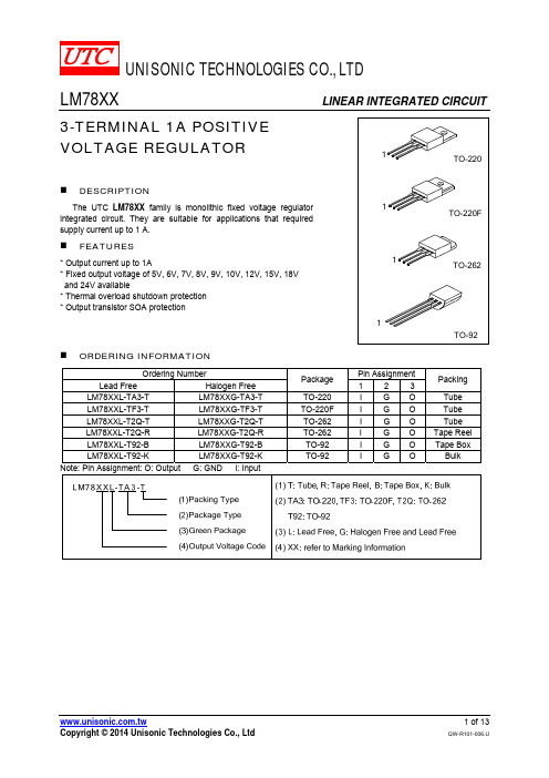
LM78XX
LINEAR INTEGRATED CIRCUIT
3-TERMINAL 1A POSITIVE VOLTAGE REGULATOR
1
TO-220
DESCRIPTION
The UTC LM78XX family is monolithic fixed voltage regulator integrated circuit. They are suitable for applications that required supply current up to 1 A.
2.0
V
70 mV
35 mV
70 mV
70 mV
8.0 mA
1.0 mA
0.5 mA
50
μV
-0.8
mV/°C
59 75
dB
1.7
A
UNISONIC TECHNOLOGIES CO., LTD
5 of 13
QW-R101-006.U
LM78XX
LINEAR INTEGRATED CIRCUIT
PARAMETER
SYMBOL
RATING
UNIT
Input voltage
VOUT=5~18V VOUT=24V
VIN
35
V
40
V
Output Current Power Dissipation
IOUT
1
A
PD
Internally Limited
W
Operating Junction Temperature Storage Temperature
东芝功放管资料

38
TIM1414-5-252
5
TIM1414-5L TIM1414-4UL NEW TIM1414-4LA TIM1414-4-252
TIM8596-4 TIM0910-4
NEW
TIM1213-4L TIM1011-4L TIM1011-4UL
NEW
36
TIM1213-4UL
TIM1011-2UL TIM8596-2 TIM0910-2 TIM1011-2L TIM1112-2
7
8
9
4
Output Power at 1dB Gain Compression (dBm)
40 Output Power at 1dB Gain Compression (W)
46
X-, Ku-band Internally Matched Power GaAs FETs/GaN HEMTs Pout vs. Frequency Map
5
■ GaN HEMTs
C-band Internally Matched Power GaN HEMT
BIAS CONDITIONS FREQUENCY BAND (GHz) 7.7-8.5
NEW 7-AA06A 7-AA04A
(Ta = 25 °C)
RF PERFORMANCE SPECIFICATIONS ABSOLUTE MAXIMUM RATINGS ELECTRICAL CHARACTERISTICS (TYP.) Tch (°C) 250 VGSoff (V) – 4.0 PACKAGE CODE IDS (@Pin = 44.0 dBm) (A) TYP. 10.0 MAX. 12.0 G✽✽ (dB) MAX. ±0.8 Tch✽ (°C) MAX. 140 50 – 10 18.0
TIM7785-16SL中文资料
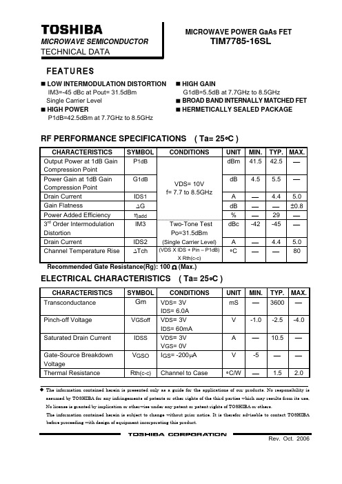
MICROWAVE POWER GaAs FETMICROWAVE SEMICONDUCTOR TIM7785-16SLTECHNICAL DATAFEATURESLOW INTERMODULATION DISTORTION HIGH GAINIM3=-45 dBc at Pout= 31.5dBm G1dB=5.5dB at 7.7GHz to 8.5GHz Single Carrier Level BROAD BAND INTERNALLY MATCHED FET HIGH POWERHERMETICALLY SEALED PACKAGEP1dB=42.5dBm at 7.7GHz to 8.5GHzRF PERFORMANCE SPECIFICATIONS ( Ta= 25°C )CHARACTERISTICS SYMBOL CONDITIONS UNITMIN. TYP.MAX. Output Power at 1dB Gain Compression PointP 1dB dBm 41.5 42.5⎯Power Gain at 1dB Gain Compression Point G 1dB dB 4.5 5.5 ⎯ Drain Current I DS1 A⎯4.45.0 Gain Flatness ΔGdB ⎯ ⎯±0.8 Power Added Efficiency ηadd VDS= 10V f= 7.7 to 8.5GHz% ⎯ 29 ⎯3rd Order Intermodulation Distortion IM3 dBc -42 -45 ⎯ Drain Current IDS2 Two-Tone Test Po=31.5dBm(Single Carrier Level) A ⎯4.45.0 Channel Temperature Rise ΔTch (VDS X IDS + Pin – P1dB)X Rth(c-c)°C ⎯ ⎯80 Recommended Gate Resistance(Rg): 100 Ω (Max.)ELECTRICAL CHARACTERISTICS ( Ta= 25°C )CHARACTERISTICS SYMBOL CONDITIONSUNITMIN. TYP.MAX.TransconductanceGm V DS = 3V I DS = 6.0AmS ⎯ 3600⎯ Pinch-off Voltage V GSoff V DS = 3VI DS = 60mAV -1.0 -2.5-4.0 Saturated Drain Current I DSS V DS = 3VV GS = 0VA⎯10.5⎯ Gate-Source Breakdown Voltage V GSO I GS = -200μA V -5 ⎯ ⎯Thermal Resistance R th(c-c) Channel to Case°C/W⎯1.52.0The information contained herein is presented only as a guide for the applications of our products. No responsibility is assumed by TOSHIBA for any infringements of patents or other rights of the third parties which may results from its use, No license is granted by implication or otherwise under any patent or patent rights of TOSHIBA or others.The information contained herein is subject to change without prior notice. It is therefor advisable to contact TOSHIBA before proceeding with design of equipment incorporating this product.ABSOLUTE MAXIMUM RATINGS ( Ta= 25°C )CHARACTERISTICS SYMBOL UNITRATINGDrain-Source Voltage V DS V 15 Gate-Source Voltage V GS V -5 Drain CurrentI DS A 14.0 Total Power Dissipation (Tc= 25 °C) P T W 75 Channel Temperature T ch °C 175 Storage TemperatureT stg°C-65 to +175PACKAGE OUTLINE (2-16G1B)Unit in mm (1) Gate (2) Source (3) DrainHANDLING PRECAUTIONS FOR PACKAGE MODELSoldering iron should be grounded and the operating time should not exceed 10 seconds at 260°C.RF PERFORMANCEOutput Power (Pout) vs. Frequency43 42 41 P o u t (d B m )407.77.98.18.38.5Frequency (GHz)Output Power(Pout) vs. Input Power(Pin)4544 43 PoutηaddPin(dBm)4241 40 39 38 37 36P o u t (d B m )80 70 ηa d d (%)60 50 40 30 201029 31 33 35 37 39POWER DISSIPATION vs. CASE TEMPERATURE906030 0 0 40 80 120 160 200Tc (°C)P T (W )IM3 vs. Output Power Characteristicsf=5MHz27-10-20 -30-40 -50 -60 I M 3(d B c )29 31 33 35 37 Pout(dBm) @Single carrier level。
LM2577-12中文资料

LM1577/LM2577SeriesSIMPLE SWITCHER ®Step-Up Voltage RegulatorGeneral DescriptionThe LM1577/LM2577are monolithic integrated circuits that provide all of the power and control functions for step-up (boost),flyback,and forward converter switching regulators.The device is available in three different output voltage ver-sions:12V,15V,and adjustable.Requiring a minimum number of external components,these regulators are cost effective,and simple to use.Listed in this data sheet are a family of standard inductors and flyback transformers designed to work with these switching regula-tors.Included on the chip is a 3.0A NPN switch and its associated protection circuitry,consisting of current and thermal limiting,and undervoltage lockout.Other features include a 52kHz fixed-frequency oscillator that requires no external compo-nents,a soft start mode to reduce in-rush current during start-up,and current mode control for improved rejection of input voltage and output load transients.Featuresn Requires few external componentsn NPN output switches 3.0A,can stand off 65V n Wide input voltage range:3.5V to 40VnCurrent-mode operation for improved transient response,line regulation,and current limit n 52kHz internal oscillatorn Soft-start function reduces in-rush current during start-up n Output switch protected by current limit,under-voltage lockout,and thermal shutdownTypical Applicationsn Simple boost regulatorn Flyback and forward regulators n Multiple-output regulatorTypical ApplicationOrdering InformationTemperature Range Package TypeOutput VoltageNSC12V 15V ADJ Package Package Drawing −40˚C ≤T A ≤+125˚C24-Pin Surface Mount LM2577M-12LM2577M-15LM2577M-ADJ M24B SO 16-Pin Molded DIP LM2577N-12LM2577N-15LM2577N-ADJ N16A N 5-Lead Surface Mount LM2577S-12LM2577S-15LM2577S-ADJ TS5B TO-2635-Straight Leads LM2577T-12LM2577T-15LM2577T-ADJ T05A TO-2205-Bent Staggered LM2577T-12LM2577T-15LM2577T-ADJ T05DTO-220LeadsFlow LB03Flow LB03Flow LB03−55˚C ≤T A ≤+150˚C4-Pin TO-3LM1577K-12/883LM1577K-15/883LM1577K-ADJ/883K04ATO-3SIMPLE SWITCHER ®is a registered trademark of National Semiconductor Corporation.DS011468-1Note:Pin numbers shown are for TO-220(T)package.June 1999LM1577/LM2577Series SIMPLE SWITCHER Step-Up Voltage Regulator©1999National Semiconductor Corporation Absolute Maximum Ratings (Note 1)If Military/Aerospace specified devices are required,please contact the National Semiconductor Sales Office/Distributors for availability and specifications.Supply Voltage45V Output Switch Voltage65V Output Switch Current (Note 2) 6.0APower DissipationInternally Limited Storage Temperature Range −65˚C to +150˚CLead Temperature (Soldering,10sec.)260˚C Maximum Junction Temperature150˚CMinimum ESD Rating(C =100pF,R =1.5k Ω)2kVOperating RatingsSupply Voltage3.5V ≤V IN ≤40V Output Switch Voltage 0V ≤V SWITCH ≤60VOutput Switch CurrentI SWITCH ≤3.0A Junction Temperature Range LM1577−55˚C ≤T J ≤+150˚C LM2577−40˚C ≤T J ≤+125˚CElectrical Characteristics—LM1577-12,LM2577-12Specifications with standard type face are for T J =25˚C,and those in bold type face apply over full Operating Temperature Range .Unless otherwise specified,V IN =5V,and I SWITCH =0.LM1577-12LM2577-12Units SymbolParameterConditionsTypicalLimit Limit (Limits)(Notes 3,4)(Note 5)SYSTEM PARAMETERS Circuit of Figure 1(Note 6)V OUT Output Voltage V IN =5V to 10V12.0V I LOAD =100mA to 800mA11.60/11.4011.60/11.40V(min)(Note 3)12.40/12.6012.40/12.60V(max)Line Regulation V IN =3.5V to 10V 20mV I LOAD =300mA 50/10050/100mV(max)Load RegulationV IN =5V20mV I LOAD =100mA to 800mA 50/10050/100mV(max)ηEfficiencyV IN =5V,I LOAD =800mA 80%DEVICE PARAMETERSI SInput Supply CurrentV FEEDBACK =14V (Switch Off)7.5mA 10.0/14.010.0/14.0mA(max)I SWITCH =2.0A25mA V COMP =2.0V (Max Duty Cycle)50/8550/85mA(max)V UV Input SupplyI SWITCH =100mA2.90V Undervoltage Lockout2.70/2.65 2.70/2.65V(min)3.10/3.153.10/3.15V(max)f OOscillator FrequencyMeasured at Switch Pin 52kHz I SWITCH =100mA 48/4248/42kHz(min)56/6256/62kHz(max)V REFOutput Reference Measured at Feedback Pin V VoltageV IN =3.5V to 40V 1211.76/11.6411.76/11.64V(min)V COMP =1.0V 12.24/12.3612.24/12.36V(max)Output Reference V IN =3.5V to 40V7mVVoltage Line RegulatorR FB Feedback Pin Input 9.7k ΩResistance G MError Amp I COMP =−30µA to +30µA 370µmho TransconductanceV COMP =1.0V 225/145225/145µmho(min)515/615515/615µmho(max)A VOLError Amp V COMP =1.1V to 1.9V 80V/V Voltage GainR COMP =1.0M Ω50/2550/25V/V(min)(Note 7) 2Electrical Characteristics—LM1577-12,LM2577-12(Continued)Specifications with standard type face are for T J=25˚C,and those in bold type face apply over full Operating Temperature Range.Unless otherwise specified,V IN=5V,and I SWITCH=0.LM1577-12LM2577-12Units Symbol Parameter Conditions Typical Limit Limit(Limits)(Notes3,4)(Note5)DEVICE PARAMETERSError Amplifier Upper Limit 2.4VOutput Swing V FEEDBACK=10.0V 2.2/2.0 2.2/2.0V(min)Lower Limit0.3VV FEEDBACK=15.0V0.40/0.550.40/0.55V(max) Error Amplifier V FEEDBACK=10.0V to15.0V±200µAOutput Current V COMP=1.0V±130/±90±130/±90µA(min)±300/±400±300/±400µA(max) I SS Soft Start Current V FEEDBACK=10.0V 5.0µAV COMP=0V 2.5/1.5 2.5/1.5µA(min)7.5/9.57.5/9.5µA(max)D Maximum Duty Cycle V COMP=1.5V95%I SWITCH=100mA93/9093/90%(min)SwitchTransconductance12.5A/VI L Switch Leakage V SWITCH=65V10µACurrent V FEEDBACK=15V(Switch Off)300/600300/600µA(max) V SAT Switch Saturation I SWITCH=2.0A0.5V Voltage V COMP=2.0V(Max Duty Cycle)0.7/0.90.7/0.9V(max)NPN Switch 4.5ACurrent Limit 3.7/3.0 3.7/3.0A(min)5.3/6.0 5.3/6.0A(max) Electrical Characteristics—LM1577-15,LM2577-15Specifications with standard type face are for T J=25˚C,and those in bold type face apply over full Operating Temperature Range.Unless otherwise specified,V IN=5V,and I SWITCH=0.LM1577-15LM2577-15Units Symbol Parameter Conditions Typical Limit Limit(Limits)(Notes3,4)(Note5)SYSTEM PARAMETERS Circuit of Figure2(Note6)V OUT Output Voltage V IN=5V to12V15.0VI LOAD=100mA to600mA14.50/14.2514.50/14.25V(min)(Note3)15.50/15.7515.50/15.75V(max)Line Regulation V IN=3.5V to12V2050/10050/100mVI LOAD=300mA mV(max)Load Regulation V IN=5V2050/10050/100mVI LOAD=100mA to600mA mV(max)ηEfficiency V IN=5V,I LOAD=600mA80% DEVICE PARAMETERSI S Input Supply Current V FEEDBACK=18.0V7.5mA(Switch Off)10.0/14.010.0/14.0mA(max)I SWITCH=2.0A25mAV COMP=2.0V50/8550/85mA(max)(Max Duty Cycle)V UV Input Supply I SWITCH=100mA 2.90V3Electrical Characteristics—LM1577-15,LM2577-15(Continued)Specifications with standard type face are for T J=25˚C,and those in bold type face apply over full Operating Temperature Range.Unless otherwise specified,V IN=5V,and I SWITCH=0.LM1577-15LM2577-15Units Symbol Parameter Conditions Typical Limit Limit(Limits)(Notes3,4)(Note5)DEVICE PARAMETERSUndervoltage 2.70/2.65 2.70/2.65V(min)Lockout 3.10/3.15 3.10/3.15V(max) f O Oscillator Frequency Measured at Switch Pin52kHzI SWITCH=100mA48/4248/42kHz(min)56/6256/62kHz(max) V REF Output Reference Measured at Feedback Pin V Voltage V IN=3.5V to40V1514.70/14.5514.70/14.55V(min)V COMP=1.0V15.30/15.4515.30/15.45V(max) Output Reference V IN=3.5V to40V10mVVoltage Line RegulationR FB Feedback Pin Input12.2kΩVoltage Line RegulatorG M Error Amp I COMP=−30µA to+30µA300µmhoTransconductance V COMP=1.0V170/110170/110µmho(min)420/500420/500µmho(max) A VOL Error Amp V COMP=1.1V to1.9V65V/VVoltage Gain R COMP=1.0MΩ40/2040/20V/V(min)(Note7)Error Amplifier Upper Limit 2.4VOutput Swing V FEEDBACK=12.0V 2.2/2.0 2.2/2.0V(min)Lower Limit0.3VV FEEDBACK=18.0V0.4/0.550.40/0.55V(max) Error Amp V FEEDBACK=12.0V to18.0V±200µAOutput Current V COMP=1.0V±130/±90±130/±90µA(min)±300/±400±300/±400µA(max) I SS Soft Start Current V FEEDBACK=12.0V 5.0µAV COMP=0V 2.5/1.5 2.5/1.5µA(min)7.5/9.57.5/9.5µA(max)D Maximum Duty V COMP=1.5V95%Cycle I SWITCH=100mA93/9093/90%(min)12.5A/VSwitchI L Switch Leakage V SWITCH=65V10µACurrent V FEEDBACK=18.0V300/600300/600µA(max)(Switch Off)V SAT Switch Saturation I SWITCH=2.0A0.5V Voltage V COMP=2.0V0.7/0.90.7/0.9V(max)(Max Duty Cycle)NPN Switch V COMP=2.0V 4.3ACurrent Limit 3.7/3.0 3.7/3.0A(min)5.3/6.0 5.3/6.0A(max) 4Electrical Characteristics—LM1577-ADJ,LM2577-ADJSpecifications with standard type face are for T J=25˚C,and those in bold type face apply over full Operating Temperature Range.Unless otherwise specified,V IN=5V,V FEEDBACK=V REF,and I SWITCH=0.LM1577-ADJ LM2577-ADJ Units Symbol Parameter Conditions Typical Limit Limit(Limits)(Notes3,4)(Note5)SYSTEM PARAMETERS Circuit of Figure3(Note6)V OUT Output Voltage V IN=5V to10V12.0VI LOAD=100mA to800mA11.60/11.4011.60/11.40V(min)(Note3)12.40/12.6012.40/12.60V(max)∆V OUT/Line Regulation V IN=3.5V to10V20mV∆V IN I LOAD=300mA50/10050/100mV(max)∆V OUT/Load Regulation V IN=5V20mV∆I LOAD I LOAD=100mA to800mA50/10050/100mV(max)ηEfficiency V IN=5V,I LOAD=800mA80% DEVICE PARAMETERSI S Input Supply Current V FEEDBACK=1.5V(Switch Off)7.5mA10.0/14.010.0/14.0mA(max)I SWITCH=2.0A25mAV COMP=2.0V(Max Duty Cycle)50/8550/85mA(max)V UV Input Supply I SWITCH=100mA 2.90V Undervoltage Lockout 2.70/2.65 2.70/2.65V(min)3.10/3.15 3.10/3.15V(max)f O Oscillator Frequency Measured at Switch Pin52kHzI SWITCH=100mA48/4248/42kHz(min)56/6256/62kHz(max)V REF Reference Measured at Feedback Pin V Voltage V IN=3.5V to40V 1.230 1.214/1.206 1.214/1.206V(min)V COMP=1.0V 1.246/1.254 1.246/1.254V(max)∆V REF/Reference Voltage V IN=3.5V to40V0.5mV∆V IN Line RegulationI B Error Amp V COMP=1.0V100nAInput Bias Current300/800300/800nA(max)G M Error Amp I COMP=−30µA to+30µA3700µmhoTransconductance V COMP=1.0V2400/16002400/1600µmho(min)4800/58004800/5800µmho(max) A VOL Error Amp V COMP=1.1V to1.9V800V/VVoltage Gain R COMP=1.0MΩ(Note7)500/250500/250V/V(min)Error Amplifier Upper Limit 2.4VOutput Swing V FEEDBACK=1.0V 2.2/2.0 2.2/2.0V(min)Lower Limit0.3VV FEEDBACK=1.5V0.40/0.550.40/0.55V(max) Error Amp V FEEDBACK=1.0V to1.5V±200µAOutput Current V COMP=1.0V±130/±90±130/±90µA(min)±300/±400±300/±400µA(max)I SS Soft Start Current V FEEDBACK=1.0V 5.0µAV COMP=0V 2.5/1.5 2.5/1.5µA(min)7.5/9.57.5/9.5µA(max)D Maximum Duty Cycle V COMP=1.5V95%I SWITCH=100mA93/9093/90%(min)∆I SWITCH/Switch12.5A/V∆V COMP Transconductance5Electrical Characteristics—LM1577-ADJ,LM2577-ADJ(Continued)Specifications with standard type face are for T J =25˚C,and those in bold type face apply over full Operating Temperature Range .Unless otherwise specified,V IN =5V,V FEEDBACK =V REF ,and I SWITCH =0.LM1577-ADJ LM2577-ADJUnits SymbolParameterConditionsTypicalLimit Limit (Limits)(Notes 3,4)(Note 5)DEVICE PARAMETERS I L Switch Leakage V SWITCH =65V10µA CurrentV FEEDBACK =1.5V (Switch Off)300/600300/600µA(max)V SATSwitch Saturation I SWITCH =2.0A0.5V Voltage V COMP =2.0V (Max Duty Cycle)0.7/0.90.7/0.9V(max)NPN Switch V COMP =2.0V4.3A Current Limit3.7/3.0 3.7/3.0A(min)5.3/6.05.3/6.0A(max)THERMAL PARAMETERS (All Versions)θJA Thermal ResistanceK Package,Junction to Ambient 35˚C/WθJC K Package,Junction to Case 1.5θJA T Package,Junction to Ambient 65θJC T Package,Junction to Case 2θJA N Package,Junction to 85Ambient (Note 8)θJA M Package,Junction 100to Ambient (Note 8)θJAS Package,Junction to 37Ambient (Note 9)Note 1:Absolute Maximum Ratings indicate limits beyond which damage to the device may occur.Operating ratings indicate conditions the device is intended to be functional,but device parameter specifications may not be guaranteed under these conditions.For guaranteed specifications and test conditions,see the Electrical Characteristics.Note 2:Due to timing considerations of the LM1577/LM2577current limit circuit,output current cannot be internally limited when the LM1577/LM2577is used as a step-up regulator.To prevent damage to the switch,its current must be externally limited to 6.0A.However,output current is internally limited when the LM1577/LM2577is used as a flyback or forward converter regulator in accordance to the Application Hints.Note 3:All limits guaranteed at room temperature (standard type face)and at temperature extremes (boldface type).All limits are used to calculate Outgoing Quality Level,and are 100%production tested.Note 4:A military RETS electrical test specification is available on request.At the time of printing,the LM1577K-12/883,LM1577K-15/883,and LM1577K-ADJ/883RETS specifications complied fully with the boldface limits in these columns.The LM1577K-12/883,LM1577K-15/883,and LM1577K-ADJ/883may also be procured to Standard Military Drawing specifications.Note 5:All limits guaranteed at room temperature (standard type face)and at temperature extremes (boldface type).All room temperature limits are 100%produc-tion tested.All limits at temperature extremes are guaranteed via correlation using standard Statistical Quality Control (SQC)methods.Note 6:External components such as the diode,inductor,input and output capacitors can affect switching regulator performance.When the LM1577/LM2577is used as shown in the Test Circuit,system performance will be as specified by the system parameters.Note 7:A 1.0M Ωresistor is connected to the compensation pin (which is the error amplifier’s output)to ensure accuracy in measuring A VOL .In actual applications,this pin’s load resistance should be ≥10M Ω,resulting in A VOL that is typically twice the guaranteed minimum limit.Note 8:Junction to ambient thermal resistance with approximately 1square inch of pc board copper surrounding the leads.Additional copper area will lower thermal resistance further.See thermal model in “Switchers Made Simple”software.Note 9:If the TO-263package is used,the thermal resistance can be reduced by increasing the PC board copper area thermally connected to the ing 0.5square inches of copper area,θJA is 50˚C/W;with 1square inch of copper area,θJA is 37˚C/W;and with 1.6or more square inches of copper area,θJA is 32˚C/W. 6Typical Performance CharacteristicsReference Voltagevs TemperatureDS011468-34Reference Voltagevs TemperatureDS011468-35Reference Voltagevs TemperatureDS011468-36∆Reference Voltagevs Supply VoltageDS011468-37∆Reference Voltagevs Supply VoltageDS011468-38∆Reference Voltagevs Supply VoltageDS011468-39Error Amp Transconductancevs TemperatureDS011468-40Error Amp Transconductancevs TemperatureDS011468-41Error Amp Transconductancevs TemperatureDS011468-42 7Typical Performance Characteristics(Continued)Error Amp Voltage Gain vs TemperatureDS011468-43Error Amp Voltage Gain vs TemperatureDS011468-44Error Amp Voltage Gain vs TemperatureDS011468-45Quiescent Current vs Temperature DS011468-46Quiescent Current vs Switch Current DS011468-47Current Limit vs TemperatureDS011468-48Current Limit Response Time vs Overdrive DS011468-49Switch Saturation Voltage vs Switch Current DS011468-50Switch Transconductance vs TemperatureDS011468-51 8Typical Performance Characteristics(Continued)Connection DiagramsFeedback Pin BiasCurrent vs TemperatureDS011468-52Oscillator Frequency vs TemperatureDS011468-53Maximum Power Dissipation (TO-263)(Note 9)DS011468-31Straight Leads 5-Lead TO-220(T)DS011468-4Top ViewOrder Number LM2577T-12,LM2577T-15,or LM2577T-ADJSee NS Package Number T05ABent,Staggered Leads 5-Lead TO-220(T)DS011468-5Top ViewOrder Number LM2577T-12Flow LB03,LM2577T-15Flow LB03,or LM2577T-ADJ Flow LB03See NS Package Number T05D9Connection Diagrams(Continued)16-Lead DIP(N)DS011468-6*No internal ConnectionTop ViewOrder Number LM2577N-12,LM2577N-15,or LM2577N-ADJSee NS Package Number N16A24-Lead Surface Mount(M)DS011468-7*No internal ConnectionTop ViewOrder Number LM2577M-12,LM2577M-15,or LM2577M-ADJSee NS Package Number M24BTO-263(S)5-Lead Surface-Mount PackageDS011468-32Top ViewDS011468-33Side ViewOrder Number LM2577S-12,LM2577S-15,or LM2577S-ADJSee NS Package Number TS5B4-Lead TO-3(K)DS011468-8Bottom ViewOrder Number LM1577K-12/883,LM1577K-15/883,or LM1577K-ADJ/883See NS Package Number K04A10LM1577-12,LM2577-12Test CircuitLM1577-15,LM2577-15Test CircuitLM1577-ADJ,LM2577-ADJ Test CircuitDS011468-30L =415-0930(AIE)D =any manufacturerC OUT =Sprague Type 673DElectrolytic 680µF,20VNote:Pin numbers shown are for TO-220(T)packageFIGURE 1.Circuit Used to Specify System Parameters for 12V VersionsDS011468-26L =415-0930(AIE)D =any manufacturerC OUT =Sprague Type 673DElectrolytic 680µF,20VNote:Pin numbers shown are for TO-220(T)packageFIGURE 2.Circuit Used to Specify System Parameters for 15V VersionsDS011468-9L =415-0930(AIE)D =any manufacturerC OUT =Sprague Type 673DElectrolytic 680µF,20VR1=48.7k in series with 511Ω(1%)R2=5.62k (1%)Note:Pin numbers shown are for TO-220(T)packageFIGURE 3.Circuit Used to Specify System Parameters for ADJ Versions11Application HintsDS011468-10Note:Pin numbers shown are for TO-220(T)package*Resistors are internal to LM1577/LM2577for12V and15V versions.FIGURE4.LM1577/LM2577Block Diagram and Boost Regulator Application 12ApplicationHints(Continued)STEP-UP (BOOST)REGULATORFigure 4shows the LM1577-ADJ/LM2577-ADJused as a Step-Up Regulator.This is a switching regulator used for producing an output voltage greater than the input supply voltage.The LM1577-12/LM2577-12and LM1577-15/LM2577-15can also be used for step-up regulators with 12V or 15V outputs (respectively),by tying the feedback pin di-rectly to the regulator output.A basic explanation of how it works is as follows.The LM1577/LM2577turns its output switch on and off at a fre-quency of 52kHz,and this creates energy in the inductor (L).When the NPN switch turns on,the inductor current charges up at a rate of V IN /L,storing current in the inductor.When the switch turns off,the lower end of the inductor flies above V IN ,discharging its current through diode (D)into the output ca-pacitor (C OUT )at a rate of (V OUT −V IN )/L.Thus,energy stored in the inductor during the switch on time is transferred to the output during the switch off time.The output voltage is controlled by the amount of energy transferred which,in turn,is controlled by modulating the peak inductor current.This is done by feeding back a portion of the output voltage to the error amp,which amplifies the difference between the feed-back voltage and a 1.230V reference.The error amp output voltage is compared to a voltage proportional to the switch current (i.e.,inductor current during the switch on time).The comparator terminates the switch on time when the two voltages are equal,thereby controlling the peak switch cur-rent to maintain a constant output voltage.Voltage and current waveforms for this circuit are shown in Figure 5,and formulas for calculating them are given in Fig-ure 6.STEP-UP REGULATOR DESIGN PROCEDUREThe following design procedure can be used to select the ap-propriate external components for the circuit in Figure 4,based on these system requirements.Given:V IN (min)=Minimum input supply voltage V OUT =Regulated output voltageI LOAD(max)=Maximum output load currentBefore proceeding any further,determine if the LM1577/LM2577can provide these values of V OUT and I LOAD(max)when operating with the minimum value of V IN .The upper limits for V OUT and I LOAD(max)are given by the following equations.V OUT ≤60V andV OUT ≤10x V IN(min)These limits must be greater than or equal to the values specified in this application.1.Inductor Selection (L)A.Voltage Options:1.For 12V or 15V outputDS011468-11FIGURE 5.Step-Up Regulator WaveformsDuty Cycle DAverage Inductor CurrentI IND(AVE)Application Hints(Continued)From Figure7(for12V output)or Figure8(for15Voutput),identify inductor code for region indicated byV IN(min)and I LOAD(max).The shaded region indicatesconditions for which the LM1577/LM2577output switchwould be operating beyond its switch current rating.Theminimum operating voltage for the LM1577/LM2577is3.5V.From here,proceed to step C.2.For Adjustable versionPreliminary calculations:The inductor selection is based on the calculation of thefollowing three parameters:D(max),the maximum switch duty cycle(0≤D≤0.9):where V F=0.5V for Schottky diodes and0.8V for fast recov-ery diodes(typically);E•T,the product of volts x time that charges the inductor:I IND,DC,the average inductor current under full load;B.Identify Inductor Value:1.From Figure9,identify the inductor code for the re-gion indicated by the intersection of E•T and I IND,DC.This code gives the inductor value in microhenries.TheL or H prefix signifies whether the inductor is rated for amaximum E•T of90V•µs(L)or250V•µs(H).2.If D<0.85,go on to step C.If D≥0.85,then calcu-late the minimum inductance needed to ensure theswitching regulator’s stability:If L MIN is smaller than the inductor value found in step B1,goon to step C.Otherwise,the inductor value found in step B1is too low;an appropriate inductor code should be obtainedfrom the graph as follows:1.Find the lowest value inductor that is greater than L MIN.2.Find where E•T intersects this inductor value to determineif it has an L or H prefix.If E•T intersects both the L and H re-gions,select the inductor with an H prefix.DS011468-27FIGURE7.LM2577-12Inductor Selection GuideDS011468-28FIGURE8.LM2577-15Inductor Selection Guide 14Application Hints(Continued)C.Select an inductor from the table of Figure10whichcross-references the inductor codes to the part numbers of three different plete specifica-tions for these inductors are available from the respec-tive manufacturers.The inductors listed in this table have the following characteristics:AIE:ferrite,pot-core inductors;Benefits of this type are low electro-magnetic interference(EMI),small physical size,and very low power dissipation(core loss).Be careful not to operate these inductors too far beyond their maximum ratings for E•T and peak current,as this will saturate the core.Pulse:powdered iron,toroid core inductors;Benefits are low EMI and ability to withstand E•T and peak current above rated value better than ferrite cores.Renco:ferrite,bobbin-core inductors;Benefits are low cost and best ability to withstand E•T and peak current above rated value.Be aware that these inductors gener-ate more EMI than the other types,and this may inter-fere with signals sensitive to noise.DS011468-12Note:These charts assume that the inductor ripple current inductor is approximately20%to30%of the average inductor current(when the regulator is underfull load).Greater ripple current causes higher peak switch currents and greater output ripple voltage;lower ripple current is achieved with larger-valueinductors.The factor of20to30%is chosen as a convenient balance between the two extremes.FIGURE9.LM1577-ADJ/LM2577-ADJ Inductor Selection Graph15Application Hints(Continued)pensation Network(R C,C C)and Output Capacitor(C OUT)SelectionR C and C C form a pole-zero compensation network that sta-bilizes the regulator.The values of R C and C C are mainly de-pendant on the regulator voltage gain,I LOAD(max),L andC OUT.The following procedure calculates values for R C,C C,and C OUT that ensure regulator stability.Be aware that thisprocedure doesn’t necessarily result in R C and C C that pro-vide optimum compensation.In order to guarantee optimumcompensation,one of the standard procedures for testingloop stability must be used,such as measuring V OUT tran-sient response when pulsing I LOAD(see Figure15).A.First,calculate the maximum value for R C.Select a resistor less than or equal to this value,and itshould also be no greater than3kΩ.B.Calculate the minimum value for C OUT using the followingtwo equations.The larger of these two values is the minimum value that en-sures stability.C.Calculate the minimum value of C C.The compensation capacitor is also part of the soft start cir-cuitry.When power to the regulator is turned on,the switchduty cycle is allowed to rise at a rate controlled by this ca-pacitor(with no control on the duty cycle,it would immedi-ately rise to90%,drawing huge currents from the inputpower supply).In order to operate properly,the soft start cir-cuit requires C C≥0.22µF.The value of the output filter capacitor is normally largeenough to require the use of aluminum electrolytic capaci-tors.Figure11lists several different types that are recom-mended for switching regulators,and the following param-eters are used to select the proper capacitor.Working Voltage(WVDC):Choose a capacitor with a work-ing voltage at least20%higher than the regulator output volt-age.Ripple Current:This is the maximum RMS value of currentthat charges the capacitor during each switching cycle.Forstep-up and flyback regulators,the formula for ripple currentisChoose a capacitor that is rated at least50%higher than thisvalue at52kHz.Equivalent Series Resistance(ESR):This is the primarycause of output ripple voltage,and it also affects the valuesof R C and C C needed to stabilize the regulator.As a result,the preceding calculations for C C and R C are only valid ifESR doesn’t exceed the maximum value specified by the fol-lowing equations.Select a capacitor with ESR,at52kHz,that is less than orequal to the lower value calculated.Most electrolytic capaci-tors specify ESR at120Hz which is15%to30%higher thanat52kHz.Also,be aware that ESR increases by a factor of2when operating at−20˚C.In general,low values of ESR are achieved by using largevalue capacitors(C≥470µF),and capacitors with highWVDC,or by paralleling smaller-value capacitors.Inductor Manufacturer’s Part NumberCode Schott Pulse RencoL4767126980PE-53112RL2442L6867126990PE-92114RL2443L10067127000PE-92108RL2444L150********PE-53113RL1954L22067127020PE-52626RL1953L33067127030PE-52627RL1952L47067127040PE-53114RL1951L68067127050PE-52629RL1950H150********PE-53115RL2445H22067127070PE-53116RL2446H33067127080PE-53117RL2447H47067127090PE-53118RL1961H68067127100PE-53119RL1960H100067127110PE-53120RL1959H150067127120PE-53121RL1958H220067127130PE-53122RL2448Schott Corp.,(612)475-11731000Parkers Lake Rd.,Wayzata,MN55391Pulse Engineering,(619)268-2400P.O.Box12235,San Diego,CA92112Renco Electronics Inc.,(516)586-556660Jeffryn Blvd.East,Deer Park,NY11729FIGURE10.Table of Standardized Inductors andManufacturer’s Part Numbers16。
稳压管大全)
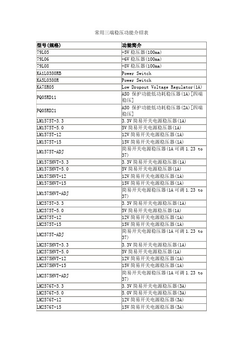
3.3V简易开关电源稳压器(1A)
LM1575T-5.0
5V简易开关电源稳压器(1A)
LM1575T-12
12V简易开关电源稳压器(1A)
LM1575T-15
15V简易开关电源稳压器(1A)
LM1575T-ADJ
简易开关电源稳压器(1A可调1.23 to 37)
LM1575HVT-3.3
LM2575HVT-ADJ
简易开关电源稳压器(1A可调1.23 to 37)
LM2576T-3.3
3.3V简易开关电源稳压器(3A)
LM2576T-5.0
5.0V简易开关电源稳压器(3A)
LM2576T-12
12V简易开关电源稳压器(3A)
LM2576T-15
15V简易开关电源稳压器(3A)
LM2576T-ADJ
79L08
-8V稳压器(100ma)
KA1L0380RB
Power Switch
KA5L0380R
Power Switch
KA78R05
Low Dropout Voltage Regulator(1A)
PQ05RD11
ASO保护功能低功耗稳压器(1A)[四端稳压]
PQ05RD21
ASO保护功能低功耗稳压器(2A)[四端稳压]
型号(规格)
功能简介
兼容型号
CA3130
高输入阻抗运算放大器
Intersil[DATA]
CA3140
高输入阻抗运算放大器
CD4573
四可编程运算放大器
MC14573
ICL7650
斩波稳零放大器
LF347(NS[DATA])
带宽四运算放大器
QS7785中文资料
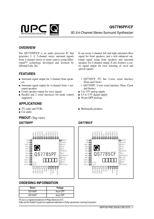
BYP(SDA) 12
ORDERING INFORMATION
Device QS7785PF QS7785CF
Package 48-pin QFP 48-pin QFP
I2C bus is a registered trademark of Philips Electronics N.V. Dolby and the double-D symbol are registered trademarks of Dolby Laboratories Licensing Corporation.
–
SCL
BASS
MUTE
PSAVE
VREFOUT
NC
VREFIN
LPC
CIN
COUT
SLOUT
SROUT
FLOUT
FROUT
QXBC4
QXBC3
QXBC2
QXBC1
VCC
QXAC4
QXAC3
QXAC2
QXAC1
BASC1
QS7785PF/CF
I/O
Description
O QEXPANDER C capacitor 4 I QEXPANDER D capacitor 1 O QEXPANDER D capacitor 2 I QEXPANDER D capacitor 3 O QEXPANDER D capacitor 4 – Ground – 4.5 to 5.5V digital supply I Input mode control (HIGH: parallel, LOW: serial) I Enhancement control (HIGH: high spread, LOW: low spread) I Serial data strobe (not applicable to QS7785CF) I Mono-to-stereo convert select (HIGH: mono to stereo mode, LOW: normal mode) I Center output control (HIGH: center on, LOW: center off) I Bypass control (HIGH: bypass, LOW: Qsurround) I/O Serial data input (also serves as ACK signal output for I2C bus) I Surround speaker control (HIGH: surround speaker on, LOW: off) I Serial clock signal input I Bass boost mode control (HIGH: bass boost on, LOW: bass boost off) I Mute signal control (HIGH: mute on, LOW: mute off) I Power save control (HIGH: power save on, LOW: power save off) O VCC/2 reference voltage output – No connection I VCC/2 reference voltage output (biased internally to VCC/2) I Center output lowpass filter I COUT output signal feedback input for front-channel output O Center signal output O Surround left-channel signal output O Surround right-channel signal output O Front left-channel signal output O Front right-channel signal output O QEXPANDER B capacitor 4 I QEXPANDER B capacitor 3 O QEXPANDER B capacitor 2 I QEXPANDER B capacitor 1 – 5 to 13V DC analog supply O QEXPANDER A capacitor 4 I QEXPANDER A capacitor 3 O QEXPANDER A capacitor 2 I QEXPANDER A capacitor 1 I Bass boost right-channel signal input
常用稳压芯片参数介绍
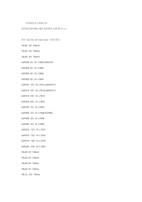
常用稳压芯片参数介绍线性稳压器件(输入输出电流相等,压降3V以上)型号稳压(V) 最大输出电流可替代型号79L05 -5V 100mA79L06 -6V 100mA79L08 -8V 100mALM7805 5V 1A L7805,LM340T5LM7806 6V 1A L7806LM7808 8V 1A L7808LM7809 9V 1A L7809LM7812 12V 1A L7812,LM340T12LM7815 15V 1A L7815,LM340T15LM7818 18V 1A L7815LM7824 24V 1A L7824LM7905 -5V 1A L7905LM7906 -6V 1A L7906,KA7906LM7908 -8V 1A L7908LM7909 -9V 1A L7909LM7912 -12V 1A L7912LM7915 -15V 1A L7915LM7918 -18V 1A L7918LM7924 -24V 1A L792478L05 5V 100mA78L06 6V 100mA78L08 8V 100ma78L09 9V 100ma78L12 12V 100ma78L15 15V 100ma78L18 18V 100ma78L24 24V 100ma开关稳压器件(电压转换效率高)型号说明最大输出电流LM1575T-3.3 3.3V简易开关电源稳压器1ALM1575T-5.0 5V简易开关电源稳压器1ALM1575T-12 12V简易开关电源稳压器1ALM1575T-15 15V简易开关电源稳压器1ALM1575T-ADJ (可调1.23V~37V) 1ALM1575HVT-3.3 3.3V简易开关电源稳压器1ALM1575HVT-5.0 5V简易开关电源稳压器1ALM1575HVT-12 12V简易开关电源稳压器1ALM1575HVT-15 15V简易开关电源稳压器1ALM1575HVT-ADJ (可调1.23V~37V) 1ALM2575T-3.3 3.3V简易开关电源稳压器1ALM2575T-5.0 5V简易开关电源稳压器1ALM2575T-12 12V简易开关电源稳压器1ALM2575T-15 15V简易开关电源稳压器1ALM2575T-ADJ (可调1.23V~ 37V) 1ALM2575HVT-3.3 3.3V简易开关电源稳压器1ALM2575HVT-5.0 5V简易开关电源稳压器1ALM2575HVT-12 12V简易开关电源稳压器1ALM2575HVT-15 15V简易开关电源稳压器1ALM2575HVT-ADJ 简易开关电源稳压器(可调1.23V~37V) 1ALM2576T-3.3 3.3V简易开关电源稳压器3ALM2576T-5.0 5.0V简易开关电源稳压器3ALM2576T-12 12V简易开关电源稳压器3ALM2576T-15 15V简易开关电源稳压器3ALM2576T-ADJ 简易开关电源稳压器(可调1.23V~37V) 3A LM2576HVT-3.3 3.3V简易开关电源稳压器3ALM2576HVT-5.0 5.0V简易开关电源稳压器3ALM2576HVT-12 12V简易开关电源稳压器3ALM2576HVT-15 15V简易开关电源稳压器3ALM2576HVT-ADJ 简易开关电源稳压器(可调1.23V~37V) 3A。
TL7715A中文资料
元器件交易网IMPORTANT NOTICETexas Instruments and its subsidiaries (TI) reserve the right to make changes to their products or to discontinueany product or service without notice, and advise customers to obtain the latest version of relevant informationto verify, before placing orders, that information being relied on is current and complete. All products are soldsubject to the terms and conditions of sale supplied at the time of order acknowledgement, including thosepertaining to warranty, patent infringement, and limitation of liability.TI warrants performance of its semiconductor products to the specifications applicable at the time of sale inaccordance with TI’s standard warranty. Testing and other quality control techniques are utilized to the extentTI deems necessary to support this warranty. Specific testing of all parameters of each device is not necessarilyperformed, except those mandated by government requirements.CERTAIN APPLICATIONS USING SEMICONDUCTOR PRODUCTS MAY INVOLVE POTENTIAL RISKS OFDEATH, PERSONAL INJURY, OR SEVERE PROPERTY OR ENVIRONMENTAL DAMAGE (“CRITICALAPPLICATIONS”). TI SEMICONDUCTOR PRODUCTS ARE NOT DESIGNED, AUTHORIZED, ORWARRANTED TO BE SUITABLE FOR USE IN LIFE-SUPPORT DEVICES OR SYSTEMS OR OTHERCRITICAL APPLICATIONS. INCLUSION OF TI PRODUCTS IN SUCH APPLICATIONS IS UNDERSTOOD TOBE FULLY AT THE CUSTOMER’S RISK.In order to minimize risks associated with the customer’s applications, adequate design and operatingsafeguards must be provided by the customer to minimize inherent or procedural hazards.TI assumes no liability for applications assistance or customer product design. TI does not warrant or representthat any license, either express or implied, is granted under any patent right, copyright, mask work right, or otherintellectual property right of TI covering or relating to any combination, machine, or process in which suchsemiconductor products or services might be or are used. TI’s publication of information regarding any thirdparty’s products or services does not constitute TI’s approval, warranty or endorsement thereof.Copyright © 1999, Texas Instruments Incorporated。
MT7885规格书-中文 _Rev1.15
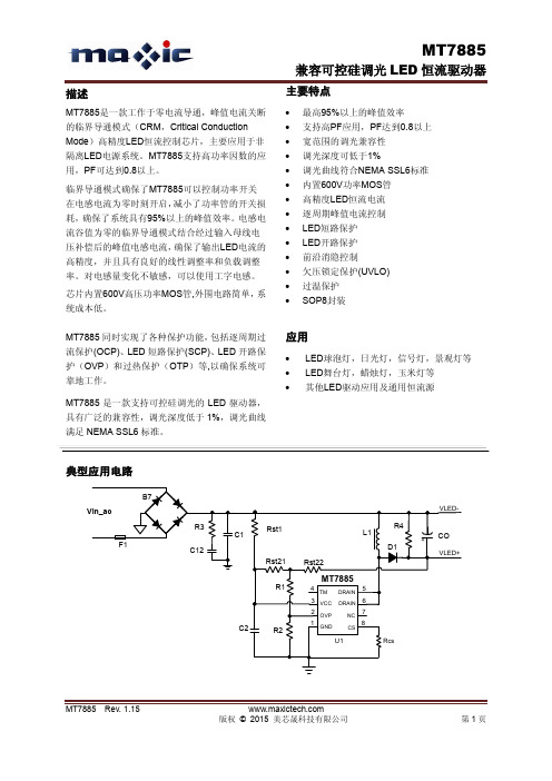
应用
LED球泡灯,日光灯,信号灯,景观灯等 LED舞台灯,蜡烛灯,玉米灯等 其他LED驱动应用及通用恒流源
典型应用电路
B7 Vin_ac R3 C1 F1 C12 Rst21 R1 Rst22 Rst1 L1 R4 CO
VLED+ VLED-
D1
MT7885
4 TM 3 VCC 2 OVP 1
D1 Rst21 R1 Rst22
MT7885
4 TM 3 VCC 2 OVP 1
DRAIN DRAIN NC CS
5 6 7 8 Rcs
C2
R2GNDU1源自开路保护的设置要注意几点: 1) 为方便设计,需使电阻由Rst21和Rst22相 等,即Rst21=Rst22,以达到平均分摊采样电压的 作用, 用于过压保护OVP值的设定。 Rst21和Rst22 的取值在150K欧姆~400K欧姆之间。如果需要支 持的母线电压偏低,则电阻Rst21和Rst22取值要 小;反之,则可以大一些,以提高系统效率。 2) 受分压电阻串R1, R2的精度影响, 以及芯 片内部参考电平的精度影响,公式(6)计算得到 的OVP阈值与实际的OVP阈值有一定的误差。准 确的OVP值可以通过调节R2的阻值来达到。OVP 值偏低,应该减小R2阻值;反之,则应加大R2的 阻值。建议R2初值取4.7K欧姆左右,用公式(6) 来确定R1的阻值,然后微调R2来精确确定OVP 值。 3) 建议将开路保护阈值设置在系统最大的
管脚描述
管脚名称 GND OVP VCC TM DRAIN NC CS 管脚号 1 2 3 4 5/6 7 8 芯片地 开路保护设置引脚及线电压采样补偿引脚 芯片电源,内部限压 15.5V 测试引脚,应用时必须悬空。 内部高压功率MOS管漏极 悬空脚 电流采样端,接采样电阻到地 描述
TM7715
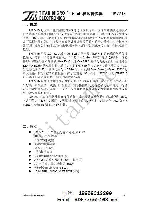
16 bit 模数转换器一、概述TM7715TM7715 是应用于低频测量的 2/3 通道的模拟前端。
该器件可以接受直接来 自传感器的低电平的输入信号,然后产生串行的数字输出。
利用 Σ-∆ 转换技术 实现了 16 位无丢失代码性能。
选定的输入信号被送到一个基于模拟调制器的增 益可编程专用前端。
片内数字滤波器处理调制器的输出信号。
通过片内控制寄存 器可调节滤波器的截止点和输出更新速率, 从而对数字滤波器的第一个陷波进行 编程。
TM7715 只需 2.7~3.3V 或 4.75~5.25V 单电源。
TM7715 是单通道全差分模 拟输入,带有一个差分基准输入。
当电源电压为 5V、基准电压为 2.5V 时,该器 件都可将输入信号范围从 0~+20mV 到 0~+2.5V 的信号进行处理。
还可处理 ±20mV~±2.5V 的双极性输入信号, 对于 TM7715 是以 AIN (-) 输入端为参考点。
当电源电压为 3V、基准电压为 1.225V 时,可处理 0~+10mV 到 0~+1.225V 的 单极性输入信号, 它的双极性输入信号范围是±10mV 到±1.225V。
因此, TM7715 可以实现单通道系统所有信号的调理和转换。
TM7715 是用于智能系统、微控制器系统和基于 DSP 系统的理想产品。
其 串行接口可配置为三线接口。
增益值、信号极性以及更新速率的选择可用串行输 入口由软件来配置。
该器件还包括自校准和系统校准选项,以消除器件本身或系 统的增益和偏移误差。
CMOS 结构确保器件具有极低功耗,掉电模式减少等待时的功耗至 20µW (典型值) 。
TM7715 采用 16 脚塑料双列直插(DIP)和 16 脚宽体(0.3 英寸) SOIC 封装和 16 脚 TSSOP 封装。
二、特点TM7715:1 个全差分输入通道的 ADC 16 位无丢失代码 0.003%非线性 可编程增益前端 增益:1~128 三线串行接口 有对模拟输入缓冲的能力 2.7~3.3V 或 4.75~5.25V 工作电压 3V 电压时,最大功耗为 1mW 等待电流的最大值为 8µA 16 脚 DIP、SOIC 和 TSSOP 封装©Titan Micro Electronics-1-16 bit 模数转换器三、功能方框图TM7715四、引脚排列与功能TM7715 的引脚排列©Titan Micro Electronics-2-16 bit 模数转换器五、引脚功能 编号 名 称 功 能TM77151SCLK串行时钟,施密特逻辑输入。
ST778资料
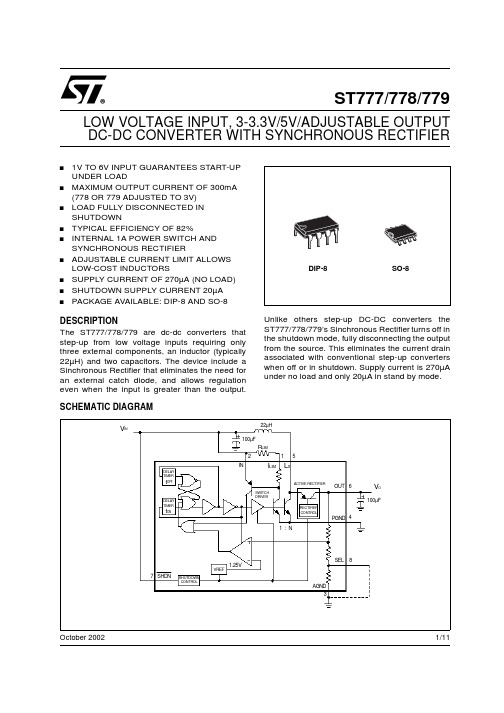
1/11October 2002s1V TO 6V INPUT GUARANTEES START-UP UNDER LOADsMAXIMUM OUTPUT CURRENT OF 300mA (778OR 779ADJUSTED TO 3V)sLOAD FULLY DISCONNECTED IN SHUTDOWNs TYPICAL EFFICIENCY OF 82%sINTERNAL 1A POWER SWITCH AND SYNCHRONOUS RECTIFIERsADJUSTABLE CURRENT LIMIT ALLOWS LOW-COST INDUCTORSs SUPPLY CURRENT OF 270µA (NO LOAD)s SHUTDOWN SUPPLY CURRENT 20µA sPACKAGE AVAILABLE:DIP-8AND SO-8DESCRIPTIONThe ST777/778/779are dc-dc converters that step-up from low voltage inputs requiring only three external components,an inductor (typically 22µH)and two capacitors.The device include a Sinchronous Rectifier that eliminates the need for an external catch diode,and allows regulation even when the input is greater than the output.Unlike others step-up DC-DC converters the ST777/778/779’s Sinchronous Rectifier turns off in the shutdown mode,fully disconnecting the output from the source.This eliminates the current drain associated with conventional step-up converters when off or in shutdown.Supply current is 270µA under no load and only 20µA in stand by mode.ST777/778/779LOW VOLTAGE INPUT,3-3.3V/5V/ADJUSTABLE OUTPUT DC-DC CONVERTER WITH SYNCHRONOUS RECTIFIERV INV O22µH100µF100µFR LIMI LIM L XINOUT PGND SEL AGND12345678SHDN1.25VVREFSHUTDOWN CONTROLDELAY TIMERDELAY TIMERt OFFt ONSWITCH DRIVERACTIVE RECTIFIERRECTIFIER CONTROL1:NSCHEMATIC DIAGRAMST777/778/7792/11ABSOLUTE MAXIMUM RATINGSAbsolute Maximum Ratings are those values beyond which damage to the device may occur.Functional operation under these condition is not implied.ORDERING CODESCONNECTION DIAGRAMPIN CONNECTIONSTHERMAL DATASymbol ParameterValue Unit V CCDC Input Voltage to GND -0.3to +7V LXSwitch off Pin Voltage -0.3to +7V Switch on Pin Voltage 30sec short to IN or OUTOUT,SHDN Output,Shutdown Voltage -0.3to +7V AGND to PGNDAnalog and Power Ground -0.3to +0.3V FBFB Pin Voltage-0.3to (OUT+0.3)V P TOT Continuous Power Dissipation (at T A =85°C)DIP-8550mW Continuous Power Dissipation (at T A =85°C)SO-8344T STG Storage Temperature Range-40to 150°C T OPOperating Ambient Temperature Range0to 85°CTYPE DIP-8SO-8ST777ST777ACN ST777ACD ST778ST778ACN ST778ACD ST779ST779ACNST779ACDPin No.SYMBOL NAME AND FUNCTION1ILIM Sets switch current limit input.Connect to IN for 1A current limit.A resistor from ILIM to IN sets lower peak inductor currents.2IN Input from battery3AGND Analog ground.Not internally connected to PGND.4PGND Power ground.Must be low impedance;solder directly to ground plane or star ground.Connect to AGND,close to the device.5LX Collector of 1A NPN power switch and emitter of Sinchronous Rectifier PNP .6OUT Voltage Output.Connect filter capacitor close to pin.7SHDNShutdown input disables power supply when low.Also disconnets load from input.Threshold is set at V IN /2.8SEL/N.C./FB -Selection pin for 3/3.3V version (778);-Not internally connected for 5V version (777);-Feedback pin for adjustable version (779).Symbol ParameterDIP-8SO-8Unit R thj-ambThermal Resistance Junction-ambient100160°C/WST777/778/7793/11ELECTRICAL CHARACTERISTICS (V IN =2.5V,C I =22µF,C O =100µF,SHDN and ILIM connected to IN,AGND connected to PGND,T A =0to 85°C,unless otherwise specified.Typical values are referred at T A =25°C)Note 1:Output in regulation,V OUT =V OUT (nominal)± 4%.Note 2:At hight V IN to V OUT differentials,the maximum load current is limited by the maximum allowable power dissipation in the package.Note 3:Start-up guaranteed under these load conditions.Note 4:Minimum value is production tested.Maximum value is guaranteed by design and is not production tested.Note 5:In the ST779supply current depends on the resistor divider used to set the output voltage.Note 6:V OUT is set to a target value of +5V by 0.1%external feedback resistors.V OUT is measured to be 5V±2.5%to guarantee the error comparator trip point.Symbol Parameter Test ConditionsMin.Typ.Max.Unit V START Start up Voltage I LOAD <10mA,T A =25°C (Note 1)1V V IN(MAX)Maximum Input Voltage (Note 1,2)6V V OOutput Voltage ST777779(set to 5V),(Note 3)I LOAD ≤ 30mA,V IN = 1.1V to 5V or I LOAD ≤ 80mA,V IN = 1.8V to 5V or I LOAD ≤ 130mA,V IN = 2.4V to 5V 4.85.05.2VOutput Voltage ST778(Note 3)SEL=0VI LOAD ≤ 50mA,V IN =1.1V to 3.3V or I LOAD ≤ 210mA,V IN =1.8V to 3.3V or I LOAD ≤ 300mA,V IN =2.4V to 3.3V 3.17 3.30 3.43VSEL=OPENI LOAD ≤ 30mA,V IN =1.1V to 3V or I LOAD ≤ 210mA,V IN =1.8V to 3V or I LOAD ≤ 300mA,V IN =2.4V to 3V2.883.00 3.12VOutput Voltage Range ST779(Note 4)2.76.5V I IN No Load Supply Current I LOAD =0mA,(Switch ON)(Note 5)270µAI SHDN Shutdown Supply Current SHDN=0V,(Switch OFF)2035µA I IN SHDNShutdown Input Current SHDN =0to V IN 15100nA SHDN =V IN to 5V 1240µA υEfficiencyI LOAD =100mA 82%V IH Shutdown Input Threshold V IN =1V to 6VV IN /2+0.25V I LIMCurrent Limit1.0A I LIM TEMPCO Current Limit TemperatureCoefficient-0.3%/°C t OFFMIN Minimum Switch Off Time 1.2µst ONMAXMaximum Switch ON TimeV IN =2.5V 4.5V IN =1.8V 6.5V IN =1V15V CESAT NPN Switch saturation VoltageI SW =400mA 0.25VI SW =600mA 0.33I SW =1000mA0.5V CESAT NPN Rectifier Forward DropI SW =400mA 0.18V I SW =600mA 0.22I SW =1000mA0.4V FB Error Comparator Trip Point ST779,over operating inputvoltage (Note 6)1.23±2%V I FB FB Pin Bias Current ST779,V FB =1.3V 50nA I LXSwitch Off Leakage Current 0.1µA Rectifier Off Leakage Current0.1µAST777/778/7794/11TYPICAL APPLICATION CIRCUITAPPLICATIONS INFORMATIONR1and R2must be placed only in ST779applications to set the output voltage according to the following equation:V OUT =(1.23)[(R1+R2)/R2]and to simplify the resistor selection:R1=R2[(V OUT /1.23)-1]It is possible to use a wide range of values for R2(10K Ωto 50K Ω)with no significant loss of accuracy thanks to the very low FB input current.To have 1%error,the current through R2must be at least 100times FB’s bias current.When large values are used for the feedback resistors (R1>50K Ω),stray output impedance at FB can incidentally add "lag"to the feedback response,destabilizing the regulator and creating a larger ripple at the output.Lead lengths and circuit board traces at the FB node should be kept pensate the loop by adding a "lead"compensation capacitor (C3,100pF to 1nF)in parallel with R1.The typical value of the L1inductor is 22µH,enough for most applications.However,are also suitable values ranging from 10µF to 47µF with a saturation rating equal to or greater than the peak switch -current limit.Efficiency will be reduced if the inductor works near its saturation limit,while will be maximized using an inductor with a low DC resistance,preferably under 0.2Ω.Connecting ILIM to V IN the maximum LX current limit (1A)is set.If this maximum value is not required is possible to reduce it connecting a resistor between ILIM and V IN (See Figure 16to choose the right value).The current limit value is misured when the switch current through the inductor begins to flatten and does’nt coincide with the max short circuit current.Even if the device is designed to tolerate a short circuit without any damage,it is strictly recommended to avoid a continuos and durable short circuit of the output to GND.To achieve the best performances from switching power supply topology,particular care to layout drawing is needed,in order to minimize EMI and obtain low noise.Moreover,jitter free operation ensures the full device functionality.Wire lengths must be minimized,filter and by-pass capacitors must be low ESR type,placed as close as possible to the integrated circuit.Solder AGND and PGND pins directly to a ground plane.ST777/778/7795/11TYPICAL CHARACTERISTICS (unless otherwise specified T j =25°C,C I =22µF,C O =100µF)Figure 1:Output Voltage vs TemperatureFigure 2:Output Voltage vs Temperature Figure 3:Efficiency vs Temperature Figure 4:Efficiency vs Input VoltageFigure 5:Efficiency vs Output CurrentFigure 6:Efficiency vs Low OutputCurrentST777/778/7796/11Figure 7:No Load Supply Current vs Input VoltageFigure 8:No Load Supply Current vs Temperature Figure 9:Shutdown Input Threshold vs Input VoltageFigure 10:Minimum Switch Off Time vs TemperatureFigure 11:Maximum Switch ON Time vs TemperatureFigure 12:FB Pin Bias Current vsTemperatureST777/778/7797/11Figure 13:Error Comparator Trip Point vs TemperatureFigure 14:Maximum Output Current vs Input Voltage Figure 15:Maximum Output Current vs Input VoltageFigure 16:Peak Inductor Current vs Current-LimitResistorST777/778/7798/11Figure 17:Line TransientFigure 18:Load Transient Figure 19:Switching WaveformFigure 20:Switching WaveformPRINTED DEMOBOARD (Not in scale)VoutVinVout (5V)IoutST777/779Vin=2.5VIout=10m A to 130m AVoutIswVin=1.1V Iout=30mAVoutIswVin=2.5VIout=30mA元器件交易网ST777/778/779 Information furnished is believed to be accurate and reliable. However, STMicroelectronics assumes no responsibility for theconsequences of use of such information nor for any infringement of patents or other rights of third parties which may result fromits use. No license is granted by implication or otherwise under any patent or patent rights of STMicroelectronics. Specificationsmentioned in this publication are subject to change without notice. This publication supersedes and replaces all informationpreviously supplied. STMicroelectronics products are not authorized for use as critical components in life support devices orsystems without express written approval of STMicroelectronics.© The ST logo is a registered trademark of STMicroelectronics© 2002 STMicroelectronics - Printed in Italy - All Rights ReservedSTMicroelectronics GROUP OF COMPANIESAustralia - Brazil - Canada - China - Finland - France - Germany - Hong Kong - India - Israel - Italy - Japan - Malaysia - Malta - MoroccoSingapore - Spain - Sweden - Switzerland - United Kingdom - United States.© 11/11。
tea1795各脚功能及电压
tea1795各脚功能及电压
TEA1795是一种高度集成化的电源管理器件,主要用于设计低功耗应用的电源控制电路。
它具有多种功能和多个引脚,下面是对TEA1795各脚功能及电压的解释:
1. VCC:VCC是电源引脚,它的作用是提供芯片的电源电压,通常为3.3V或5V。
2. GND:GND是地引脚,它连接到电路的地,用于形成电路的回路。
3. FB:FB是反馈引脚,它连接到电源控制回路中的反馈元件,用于控制输出电压。
4. COMP:COMP是补偿引脚,它连接到电源控制回路中的补偿元件,用于调整输出电压的稳定性。
5. EN:EN是使能引脚,它用于控制芯片的开关状态,通常为高电平时芯片开启,低电平时芯片关闭。
6. SS:SS是同步引脚,它用于控制输出电压的开关频率,通常连接到一个同步信号源。
7. VCC_SEN:VCC_SEN是电源传感器引脚,它连接到电源传感器,用于检测电源电压。
8. GND_SEN:GND_SEN是地传感器引脚,它连接到地传感器,用于检测地电平。
9. VCC_AUX:VCC_AUX是辅助电源引脚,它连接到辅助电源,用于提供辅助功能的电源。
10. SEL:SEL是选择引脚,它用于控制芯片的输出模式,通常为高电平时为PWM 模式,低电平时为Pulse Skipping模式。
11. SYNC:SYNC是同步引脚,与SS功能相同。
12. OUT:OUT是输出引脚,它连接到负载,用于输出电源电压。
在正常情况下,TEA1795的工作电压为3.3V或5V,具体电压取决于电路的设计和应用。
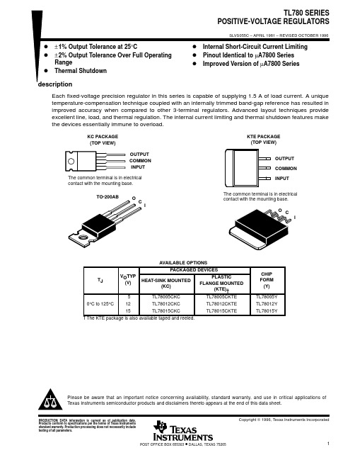
TL780-12资料
10171(1)(2)(3)IMPORTANT NOTICETexas Instruments (TI) reserves the right to make changes to its products or to discontinue any semiconductor product or service without notice, and advises its customers to obtain the latest version of relevant information to verify, before placing orders, that the information being relied on is current.TI warrants performance of its semiconductor products and related software to the specifications applicable at the time of sale in accordance with TI’s standard warranty. Testing and other quality control techniques are utilized to the extent TI deems necessary to support this warranty. Specific testing of all parameters of each device is not necessarily performed, except those mandated by government requirements.Certain applications using semiconductor products may involve potential risks of death, personal injury, or severe property or environmental damage (“Critical Applications”).TI SEMICONDUCTOR PRODUCTS ARE NOT DESIGNED, INTENDED, AUTHORIZED, OR WARRANTED TO BE SUITABLE FOR USE IN LIFE-SUPPORT APPLICATIONS, DEVICES OR SYSTEMS OR OTHER CRITICAL APPLICATIONS.Inclusion of TI products in such applications is understood to be fully at the risk of the customer. Use of TI products in such applications requires the written approval of an appropriate TI officer. Questions concerning potential risk applications should be directed to TI through a local SC sales office.In order to minimize risks associated with the customer’s applications, adequate design and operating safeguards should be provided by the customer to minimize inherent or procedural hazards.TI assumes no liability for applications assistance, customer product design, software performance, or infringement of patents or services described herein. Nor does TI warrant or represent that any license, either express or implied, is granted under any patent right, copyright, mask work right, or other intellectual property right of TI covering or relating to any combination, machine, or process in which such semiconductor products or services might be or are used.Copyright © 1996, Texas Instruments Incorporated。
塞弗朗 7885 电视信号表计 使用手册说明书
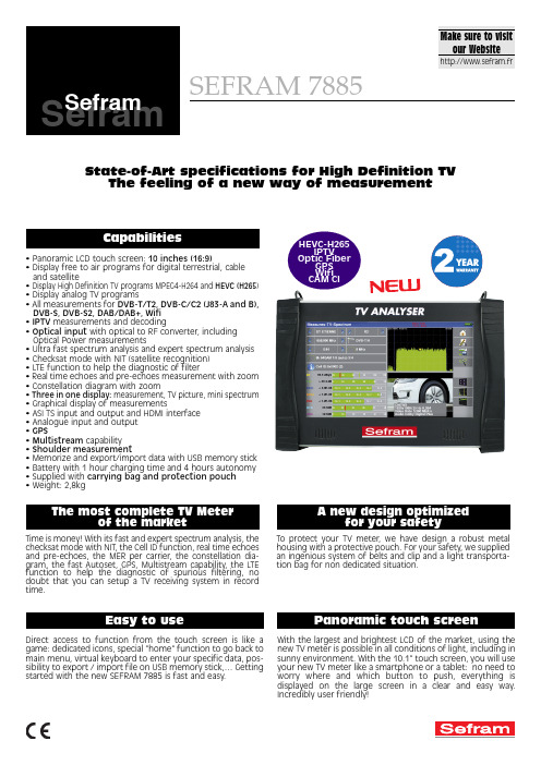
SEFRAM 7885 SeframTime is money! With its fast and expert spectrum analysis, the checksat mode with NIT, the Cell ID function, real time echoes and pre-echoes, the MER per carrier, the constellation dia-gram, the fast Autoset, GPS, Multistream capability, the LTE function to help the diagnostic of spurious filtering, no doubt that you can setup a TV receiving system in record time.To protect your TV meter, we have design a robust metal housing with a protective pouch. For your safety, we supplied an ingenious system of belts and clip and a light transporta-tion bag for non dedicated situation.A new design optimizedfor your safetyDirect access to function from the touch screen is like a game: dedicated icons, special "home" function to go back to main menu, virtual keyboard to enter your specific data, pos-sibility to export / import file on USB memory stick,… Getting started with the new SEFRAM 7885 is fast and easy.With the largest and brightest LCD of the market, using the new TV meter is possible in all conditions of light, including in sunny environment. With the 10.1" touch screen, you will use your new TV meter like a smartphone or a tablet: no need to worry where and which button to push, everything is displayed on the large screen in a clear and easy way. Incredibly user friendly!Panoramic touch screen• Panoramic LCD touch screen: 10 inches (16:9)• Display free to air programs for digital terrestrial, cable and satellite• Display High Definition TV programs MPEG4-H264 and HEVC (H265)• Display analog TV programs• All measurements for DVB-T/T2, DVB-C/C2 (J83-A and B), DVB-S, DVB-S2, DAB/DAB+, Wifi•IPTV measurements and decoding• Optical input with optical to RF converter, including Optical Power measurements• Ultra fast spectrum analysis and expert spectrum analysis • Checksat mode with NIT (satellite recognition)• LTE function to help the diagnostic of filter• Real time echoes and pre-echoes measurement with zoom • Constellation diagram with zoom• Three in one display:measurement, TV picture, mini spectrum • Graphical display of measurements• ASI TS input and output and HDMI interface• Analogue input and output• GPS• Multistream capability• Shoulder measurement• Memorize and export/import data with USB memory stick • Battery with 1 hour charging time and 4 hours autonomy • Supplied with carrying bag and protection pouch• Weight: 2,8kgState-of-Art specifications for High Definition TVThe feeling of a new way of measurementFT7885 A01 - Specifications can be updated without notice32, rue Edouard Martel - B.P. 55 - 42009 - St Etienne cedex 2Tel.+33 (0).4.77.59 36 81Supplied with:main adaptor (90-245V with European plug), user's manual on CD ROM, F/F and F/BNC adaptor, carrying protective pouch,belt clip, transportation pouch.(*): the display of digital encrypted programs is possible, if user has a valid subsciption card and if the encryption type is supported bythe TV Meter. Please check with our sales department when ordering. Dolby is a trade mark of Dolby Laboratories.978852000Transportation handcase978361000Car cigar lighter adapter978853000Audio/video cableOptional accessories: Car cigar lighterP/N 978361000Transportation hardcase P/N 978852000A/V cableP/N 978852000。
LHI778中文资料
产品描述
热释电红外传感器LHI778
热释电红外线感测器是利用温度变化的特征来探测红外线的辐射,采用双灵敏元互补的方法抑制温度变化产生的干扰,提高了感测器的工作稳定性。
产品应用广泛,例如,保险装置,防盗报警器,感应门,自动灯具,智慧玩具等。
型号:LHI778
封装:TO-5
红外接收电极:2×1 mm2,2个灵敏元
基片材料:硅
灵敏度:≥3300V/W
输出平衡度<10%
噪声≤50μVpp (25℃,0.3^10Hz)
探测率:(D*)≥5×10^7 cmHz^/W (1Hz,100℃,1HzBw)
源极电压:0.2-1.5V (VD=10V,Rs=47kΩ,25℃)
工作电压:2-15V (Rs=47KΩ,25℃)
输出阻抗:≤10KΩ(RS=47KΩ)
工作温度:-40℃- +85℃
保存温度: -40℃- +85℃
视场139°×139°
说明:该传感器采用热释电材料极化随温度变化的特性探测红外辐射,采用双灵敏元互补方法抑制温度变化产生的干扰,提高了传感器的工作稳定性。
使用:
1、上述特性指标是在源极电阻R2=47KΩ条件下测定的,用户使用传感器时,可根据自己的需要调整R2的大小。
2、注意灵敏元的位置及视场大小,以便得到最佳光学设计。
3、所有电压信号的测量都是采用峰一峰值定标。
平衡度B中的EA和EB分别表示两个灵敏元的电压输出信号的峰一峰值。
4、使用传感时,管脚的弯曲或焊接部位应离开管脚基部4mm以上。
5、使用传感器前,应先参考说明书,尤其要防止接错管脚。
- 1、下载文档前请自行甄别文档内容的完整性,平台不提供额外的编辑、内容补充、找答案等附加服务。
- 2、"仅部分预览"的文档,不可在线预览部分如存在完整性等问题,可反馈申请退款(可完整预览的文档不适用该条件!)。
- 3、如文档侵犯您的权益,请联系客服反馈,我们会尽快为您处理(人工客服工作时间:9:00-18:30)。
90 80 Po 70 60 50
3
元器件交易网
TIM7785-12UL
Power Dissipation vs. Case Temperature
100
80
P T (W)
60
40
20
0 0 40 80 120 160 200 Tc (•Ž)
元器件交易网
MICROWAVE POWER GaAs FET MICROWAVE SEMICONDUCTOR
TIM7785-12UL
TECHNICAL DATA FEATURES
n HIGH POWER P1dB=41.5dBm at 7.7GHz to 8.5GHz n HIGH GAIN G1dB=8.5dB at 7.7GHz to 8.5GHz n BROAD BAND INTERNALLY MATCHED FET n HERMETICALLY SEALED PACKAGE
PACKAGE OUTLINE (2-16G1B)
0.7±0.15 4 – C1.0
(1)
Unit in mm 2.5 MIN.
(1) Gate (2) Source (3) Drain
(2)
(2)
(3)
20.4±0.3 0.1 -0.05 24.5 MAX. 16.4 MAX.
+0.1
2.5 MIN.
Rev. Oct. 2006
元器件交易网
TIM7785-12UL
ABSOLUTE MAXIMUM RATINGS ( Ta= 25°C )
CHARACTERISTICS Drain-Source Voltage Gate-Source Voltage Drain Current Total Power Dissipation (Tc= 25 °C ) Channel Temperature Storage SYMBOL VDS VGS IDS PT Tch Tstg UNIT V V A W °C °C RATING 15 -5 10.0 62.5 175 -65 to +175
4
(Single Carrier Level)
(VDS X IDS + Pin – P1dB) X Rth(c-c)
SYMBOL P1dB
CONDITIONS
UNIT dBm
MIN. 40.5 7.5 -44
TYP. MAX. 41.5 8.5 3.2 38 -47 3.2 3.8 ±0.6 3.8 80
RF PERFORMANCE SPECIFICATIONS ( Ta= 25°C )
CHARACTERISTICS Output Power at 1dB Gain Compression Point Power Gain at 1dB Gain Compression Point Drain Current Gain Flatness Power Added Efficiency 3rd Order Intermodulation Distortion Drain Current Channel Temperature Rise IDS2 ∆Tch IDS1 ∆G G1dB VDS= 10V dB A dB % Two Tone Test Po=30.5dBm
gm
VGSoff IDSS VGSO Rth(c-c)
CONDITIONS VDS= 3V IDS= 4.0A VDS= 3V IDS= 40mA VDS= 3V VGS= 0V IGS= -140µA Channel to Case
UNIT mS V A V °C/W
MIN. -1.0 -5
VDS= 10V IDS≅ 3.2A Pin= 33dBm
Output Power vs. Input Power 43 42 41 40 Po (dBm) 39 ā add 38 37 36 35 34 26 28 30 32 Pin (dBm) 34 36 40 30 20 10 0 ā add (% )
f = 7.5 to 8.5GHz
ηadd
IM3
dBc A °C
Recommended gate resistance(Rg) : Rg= 100 Ω(MAX.)
ELECTRICAL CHARACTERISTICS ( Ta= 25°C )
CHARACTERISTICS Transconductance Pinch-off Voltage Saturated Drain Current Gate-Source Breakdown Voltage Thermal Resistance SYMBOL
TYP. 2500 -2.5 7.2 2.0
MAX. -4.0 2.4
uThe information contained herein is presented only as a guide for the applications of our products. No responsibility is assumed by TOSHIBA for any infringements of patents or other rights of the third parties which may results from its use, No license is granted by implication or otherwise under any patent or patent rights of TOSHIBA or others. The information contained herein is subject to change without prior notice. It is therefor advisable to contact TOSHIBA before proceeding with design of equipment incorporating this product.
2.6±0.3
17.4± 0.4
8.0±0.2
0.2 MAX.
1.4± 0.3
HANDLING PRECAUTIONS FOR PACKAGE MODEL
Soldering iron should be grounded and the operating time should not exceed 10 seconds at 260°C.
IM3 vs. Output Power Characteristics - 20
VDS= 10V IDS≅ 3.2A f= 8.1GHz ∆f= 5MHz
- 30 IM3 (dBc)
- 40
- 50
- 60 25 27 29 31 33 35
Po(dBm), Single Carrier Level
2
2.4± 0.3
5.5 MAX.
元器件交易网www.cecb2b.cΒιβλιοθήκη mTIM7785-12UL
RF PERFORMANCE
Output Power vs. Frequency 44 43 Po (dBm) 42 41 40 39 7.4 7.6 7.8 8 8.2 8.4 8.6 8.8 Frequency (GHz)
