安全标志平面图
工地现场安全警示标识布置参考
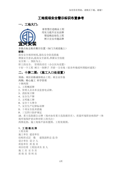
工地现场安全警示标识布置参考一、工地大门:靠智慧打造精品工程用实力提升宜安品牌塑造精品绿色工程树立宜安卓越品牌宜兴安装多做点标志贴在醒目位置(如门卫或设施上)标语:落实安全规章制度,强化安全防范措施增强安全意识,提高安全素质,掌握安全技能安全第一,预防为主。
职工的安全,管理的责任(办公区内设置)干好一个工程树立一块牌子开辟一方市场(宿舍外墙或外围临时建筑)二、十牌二图:(施工入口处设置)顶部:项目名称或铸精品工程,树企业形象两侧:精心施工科学管理十牌两图1、工程概括牌2、管理人员名单及监督电话牌,3、消防保卫牌4、安全生产牌5、文明施工牌6、安全十大禁令7、安全生产纪律标语牌8、十项安全技术措施9、三宝四口防护规定10、重大危险源公示牌(场内如有重大危险源存在)、质量环境职业病保护(体现环境保护意识和对职工的关注)两图是指:施工现场平面布置图、工程效果图。
1.工程概况牌工程名称施工单位建设单位结构形式层数建筑面积总造价设计单位设计人质监单位质监员项目经理工程技术负责人施工员安全员质检员资料员开工日期年月日计划竣工日期年月日备注质安领导小组组长:副组长:成员:消防领导小组组长:副组长:成员:2.管理人员名单及监督电话牌项目经理项目副经理技术负责人总施工施工员质量员安全员资料员材料员预算员监督电话:3.消防保卫牌一、贯彻执行有关的消防法规及公司防火安全管理制度和消防检查监护制度,加强施工现场防火安全管理,确保工程消防安全。
二、实行"谁主管,谁负责"原则,贯彻"预防为主,防消结合"方针,建立以工地项目经理为主的义务消防组织并健全防火安全责任制管理网络。
三、施工现场内外消防道路和通道应保证畅通,工地应按消防要求配制有效的消防设施及器材。
四、施工现场动用明火必须有审批手续和监护人,必须时应采取隔离措施。
五、易燃物品必须定点存放好,在消防区内应设置明显的防火、安全、警告标志牌。
五图二牌

说明】:1、“五牌二图”由项目经理部在工程进场后15 天内设计完成,交安全部统一制作,现场展示。
2、“五牌二图”设计文稿打印归档。
3、“五牌二图”内容包括:“五牌”:工程概况牌、管理人员名单及监督电话牌、安全生产牌、消防保卫牌、文明施工牌、“二图”:施工现场总平面布置图、安全警示标志平面图工程概况牌管理人员名单及监督电话牌安全生产牌一、建筑施工重地严禁非施工人员进入,凡进入施工现场的人员,都必须戴好安全帽。
二、参加施工的操作人员,必须懂得本工种的安全技术操作规程。
遵章操作。
工作中禁止饮酒、赌博、打闹、冒险作业。
现场内的操作人员,不准穿拖鞋、高跟鞋、赤脚和赤膊穿短裤,吸烟要到指定地点。
三、工作前必须检查设备,确认安全后方可操作,现场所有的机电设备,要设专人负责,非操作者严禁乱开、舌L动。
机电设备维修时,必须拉闸停车,设专人监护。
四、施工现场必须做到“三通一平”,道路畅通,禁止攀登脚手架上下,禁止在支设的模板梁底板上操作行走,禁止任意投扔工具和其它物料。
各工种在同一工作场所立体交叉作业时,必须按规定搭设防护棚。
五、禁止擅自乱拆已搭好的脚手架,未经工地负责人进行安全交底的施工项目,不得自行盲目操作。
六、禁止在现场设有危险标志和专门围栏场所行走及起重臂活动区域逗留与操作。
七、施工现场要充分发挥“三宝”的作用,操作者要按要求戴好安全帽,高处作业要戴好安全带,挂好安全网。
八、非电工禁止乱接乱拉电线,在电线上禁止搭挂衣物,电闸箱内禁止放工具及物品,夜间施工必须有足够的照明,宿舍照明高度低于 2.4m必须使用安全电压。
九、现场洞、坑、沟、槽必须按规定设置安全护栏及警告标志。
十、现场发生伤亡事故要采取紧急救护措施,减少人员伤亡,同时要保护好现场,及时上报各有关部门。
文明施工牌一、施工现场周边应设置符合要求的围挡,实行封闭式施工。
二、工地的大门要牢固可靠,门扇开关灵活。
大门以内的现场要硬化处理三、各项临时设施、材料和机具设备等,应按施工总平面图布置堆放,整齐稳固。
中建安全防护标志标识标准化图册(下)
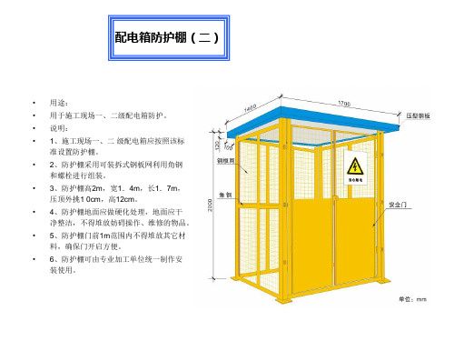
装使用。
C19、气瓶存放
气瓶托架
• 说明: • 1、适用于现场气瓶的垂直吊运。 • 2、托架边框部分宜采用L45×45×5角铁焊接。 • 3、托架围栏宜采用12mm螺纹钢焊接。 • 4、托架的长为0.8米、宽为0.6米、高为1.4米。 • 5、托架应悬挂警示标牌(禁止烟火)。
氧气、乙炔瓶安全距离
• 说明: • 1、氧气、乙炔瓶距明火间距不得小于10米。 • 2、氧气、乙炔瓶存放间距不得小于5米。 • 3、氧气、乙炔不得平放和曝晒。 • 4、氧气、乙炔瓶储存室应分开存放。
C20、消防安全
• 说明:
• 1、施工现场需制定完善的消防制度及措施。有经过审批的消防应急预案,并定期进行演练。
外电线路防护
• 说明 • 1.在建工程不得在外电线路正下方施工、搭
设作业棚、建造生活设施或堆放构件、架具、 材料等。 • 2.在建工程(含脚手架)的周边与外电架空线路 的边线之 间的最小安全操作距离应符合下表规 定:
3.施工现场开挖沟槽边缘与外电埋地电缆沟 槽边缘之问的距离不得小于0.5m。 4.架设安全防护设施应是一种绝缘隔离防护 措施,宜通过采用木、竹或其他绝缘材料增 设屏障、遮拦、围栏、保护网等与外电线路 实现强制性绝缘隔离,并须在隔离处悬挂醒 目的警告标志牌。
(宽x高)。
• 3、色彩:太门颜色为白色或不锈钢本色。 • 4、文字组合及其它: 每扇门正腰安装一块面积为l米×2米或1 × 3米(高×宽)的薄铁板,颜色为中
建蓝色(C100M30,以下简称蓝色),上面用白色隶书体宇(刘炳森手书)书写“中国建筑”宇样,如门为 铁板制成,正腰则涂为蓝色,面积同上。门柱:门柱截面尺寸建议为0.8×0. 8米,高度为2.2米,其中 0.2米为柱帽高度,柱帽为梯形,顶面积为0.6×0.6米。门柱通体为蓝色。两柱帽上方可加灯箱,各单 位根据需要自行决定。
ISO 23601-2009 安全标识 疏散平面图标志(中英文,GB T25894)
Reference numberISO 23601:2009(E)INTERNATIONALSTANDARD ISO 23601First edition2009-02-15Safety identification — Escape andevacuation plan signsIdentification de sécurité — Plans d'évacuation et de secoursISO 23601:2009(E)PDF disclaimerThis PDF file may contain embedded typefaces. I n accordance with Adobe's licensing policy, this file may be printed or viewed but shall not be edited unless the typefaces which are embedded are licensed to and installed on the computer performing the editing. In downloading this file, parties accept therein the responsibility of not infringing Adobe's licensing policy. The ISO Central Secretariat accepts no liability in this area.Adobe is a trademark of Adobe Systems Incorporated.Details of the software products used to create this PDF file can be found in the General I nfo relative to the file; the PDF-creation parameters were optimized for printing. Every care has been taken to ensure that the file is suitable for use by ISO member bodies. In the unlikely event that a problem relating to it is found, please inform the Central Secretariat at the address given below.COPYRIGHT PROTECTED DOCUMENT© ISO 2009All rights reserved. Unless otherwise specified, no part of this publication may be reproduced or utilized in any form or by any means, electronic or mechanical, including photocopying and microfilm, without permission in writing from either I SO at the address below or ISO's member body in the country of the requester.ISO copyright officeCase postale 56 x CH-1211 Geneva 20Tel. + 41 22 749 01 11Fax + 41 22 749 09 47E-mail copyright@Web Published in SwitzerlandISO 23601:2009(E)Contents PageForeword (iv)Introduction (v)1 Scope (1)2 Normativereferences (1)definitions (1)3 Termsand4 General (2)5 Designrequirements (2)6 Size of plan elements (3)representation (4)and7 Contents7.1 Header (4)plan (4)7.2 Overview7.3 Escape plan detail (4)notices (5)7.4 Safety7.5 Legend (5)information (5)7.6 Other7.7 Use of colours (6)7.7.1 Escaperoutes (6)signs (6)7.7.2 Safety7.7.3 Point of location of the user (6)colour (6)7.7.4 Background7.7.5 Outline of facility structural elements (6)7.7.6 Header (6)7.7.7 Text (6)8 Materials (6)location (6)and9 Installationrevision (7)and10 InspectionAnnex A (informative) Examples of escape plans (8)Bibliography (13)。
“五牌一图”(七牌两图)的基本内容

13.8.3示例1“五牌一图”(七牌两图)的基本内容1. 按《检查标准》(JGJ 59—99)规定,大门口标牌为“五牌一图”,即工程概况牌、管理人员名单及监督电话牌、消防保卫牌、安全生产牌、文明施工牌和施工现场总平面图等内容。
2. 有的地区推广“七牌两图”,即消防保卫牌、材料管理牌、环境卫生管理牌、安全生产牌、文明施工牌、工程概况牌、项目管理人员名单及监督电话牌和施工现场总平面图、施工现场安全标志平面图等内容。
3. “七牌两图”参考内容示例(1)消防保卫管理制度(消防保卫牌)1)施工现场设消防保卫负责人,建立消防组织、设置义务消防队员。
2)制定消防管理制度;临建经审批且符合防火要求。
3)建立消防、保卫制度和记录。
4)确保消防道路畅通,加强易燃易爆物品管理。
5)按规定配置消防器材;火灾危险地带设置消防箱、配置消防器材;重要防火点悬挂警告牌;动火作业需审批,并设专人监控。
6)供电设施、线路符合要求。
7)外出物资执行出门证制度。
8)施工现场禁止吸烟。
(2)材料管理制度(材料管理牌)1)严把材料进场关,严禁不合格材料进入施工现场。
2)进场材料必须按规定取样试验,确认合格后方可使用。
3)现场材料堆放有序,机砖成丁、砂石成方、水泥成垛、钢材分类堆放,并悬挂标识牌。
4)材料管理人员持证上岗。
5)材料发放专人负责。
6)材料使用严格执行限额领料制度,杜绝材料浪费。
7)现场剩余材料及时回收入库。
(3)环境卫生管理制度(环境卫生管理牌)1)工地周围连续设置坚固、稳定、整洁、美观的围挡。
2)物料不准乱堆乱放,在马路、边道存放时,必须有批准手续。
3)施工现场建立防粉尘、防噪声措施及施工不扰民措施。
4)施工工地设专人清扫和管理环境卫生,并经常保持环境清洁。
5)工地工程垃圾和生活垃圾设专人管理,做到随产随清。
6)运输物料的车辆不遗漏,不准车轮带泥,出门口时必须经过冲洗。
7)作业污染道路时要及时清理干净。
(4)安全生产管理制度(安全生产管理牌)1)施工现场设置安全标志牌,通道口搭设防护棚。
ISO 23601-2009_安全标识—疏散平面图标志_20090

Reference numberISO 23601:2009(E)INTERNATIONALSTANDARD ISO 23601First edition2009-02-15Safety identification — Escape andevacuation plan signsIdentification de sécurité — Plans d'évacuation et de secoursISO 23601:2009(E)PDF disclaimerThis PDF file may contain embedded typefaces. I n accordance with Adobe's licensing policy, this file may be printed or viewed but shall not be edited unless the typefaces which are embedded are licensed to and installed on the computer performing the editing. In downloading this file, parties accept therein the responsibility of not infringing Adobe's licensing policy. The ISO Central Secretariat accepts no liability in this area.Adobe is a trademark of Adobe Systems Incorporated.Details of the software products used to create this PDF file can be found in the General I nfo relative to the file; the PDF-creation parameters were optimized for printing. Every care has been taken to ensure that the file is suitable for use by ISO member bodies. In the unlikely event that a problem relating to it is found, please inform the Central Secretariat at the address given below.COPYRIGHT PROTECTED DOCUMENT© ISO 2009All rights reserved. Unless otherwise specified, no part of this publication may be reproduced or utilized in any form or by any means, electronic or mechanical, including photocopying and microfilm, without permission in writing from either I SO at the address below or ISO's member body in the country of the requester.ISO copyright officeCase postale 56 x CH-1211 Geneva 20Tel. + 41 22 749 01 11Fax + 41 22 749 09 47E-mail copyright@Web Published in SwitzerlandISO 23601:2009(E)Contents PageForeword (iv)Introduction (v)1 Scope (1)2 Normativereferences (1)definitions (1)3 Termsand4 General (2)5 Designrequirements (2)6 Size of plan elements (3)representation (4)and7 Contents7.1 Header (4)plan (4)7.2 Overview7.3 Escape plan detail (4)notices (5)7.4 Safety7.5 Legend (5)information (5)7.6 Other7.7 Use of colours (6)7.7.1 Escaperoutes (6)signs (6)7.7.2 Safety7.7.3 Point of location of the user (6)colour (6)7.7.4 Background7.7.5 Outline of facility structural elements (6)7.7.6 Header (6)7.7.7 Text (6)8 Materials (6)location (6)and9 Installationrevision (7)and10 InspectionAnnex A (informative) Examples of escape plans (8)Bibliography (13)ISO 23601:2009(E)ForewordISO (the International Organization for Standardization) is a worldwide federation of national standards bodies (I SO member bodies). The work of preparing I nternational Standards is normally carried out through I SO technical committees. Each member body interested in a subject for which a technical committee has been established has the right to be represented on that committee. International organizations, governmental and non-governmental, in liaison with I SO, also take part in the work. I SO collaborates closely with the International Electrotechnical Commission (IEC) on all matters of electrotechnical standardization.International Standards are drafted in accordance with the rules given in the ISO/IEC Directives, Part 2.The main task of technical committees is to prepare I nternational Standards. Draft I nternational Standards adopted by the technical committees are circulated to the member bodies for voting. Publication as an International Standard requires approval by at least 75 % of the member bodies casting a vote.Attention is drawn to the possibility that some of the elements of this document may be the subject of patent rights. ISO shall not be held responsible for identifying any or all such patent rights.SO 23601 was prepared by Technical Committee I SO/TC 145, Graphical sym bols, Subcommittee SC 2, Safety identification, signs, shapes, symbols and colours.ISO 23601:2009(E)IntroductionThere is a need to standardize a system of communicating escape routes in facilities that relies as little as possible on the use of words to achieve understanding.Continued growth in international trade, travel and mobility of labour requires a common method of conveying this important safety information to the occupants of facilities.The use of this International Standard is expected to reduce risk by providing a means of improved training and education and to reduce possible confusion in times of emergency.Through the use of ISO 7010 safety signs, colour coding and specific design requirements, this International Standard establishes a common method of illustrating the position of the viewer in relation to designated escape routes leading to emergency exits and the location of fire safety and emergency equipment close and adjacent to escape routes.Escape plans are an integral part of a facility’s system of safety signs and play an integral role in a building owner’s fire safety management plan. Escape plans are a necessary component of a facility’s safety way guidance system (see ISO 16069).NOTE Some countries’ statutory regulations may differ in some respect from those given in this nternational Standard.INTERNATIONAL STANDARD ISO 23601:2009(E) Safety identification — Escape and evacuation plan signsIMPOR TANT — The electronic file of this document contains colours which are considered to be useful for the correct understanding of the document. Users should therefore consider printing this document using a colour printer.1 ScopeThis International Standard establishes design principles for displayed escape plans that contain information relevant to fire safety, escape, evacuation and rescue of the facility's occupants. These plans may also be used by intervention forces in case of emergency.These plans are intended to be displayed as signs in public areas and workplaces.This I nternational Standard is not intended to cover the plans to be used by external safety services nor detailed professional technical drawings for use by specialists.2 Normative referencesThe following referenced documents are indispensable for the application of this document. For dated references, only the edition cited applies. For undated references, the latest edition of the referenced document (including any amendments) applies.ISO 3864-1:2002, Graphical symbols — Safety colours and safety signs — Part 1: Design principles for safety signs in workplaces and public areasISO 3864-3, Graphical symbols — Safety colours and safety signs — Part 3: Design principles for graphical symbols for use in safety signsISO 7010, Graphical sym bols — Safety colours and safety signs — Safety signs used in workplaces and public areasISO 17724, Graphical symbols — VocabularyISO 17398, Safety colours and safety signs — Classification, performance and durability of safety signs3 Terms and definitionsFor the purposes of this document, the terms and definitions given in ISO 17724 and the following apply.3.1emergency safety noticeinstructions for occupants, to be followed in case of emergencyISO 23601:2009(E)3.2escape planplan displayed for the occupants of a facility on which are illustrated the necessary elements for escape and on which may appear information required for evacuation, rescue and for a first intervention3.3escape routedesignated route to a place of intended safety3.4escape plan detaildetailed representation of the area marked in the overview plan based on floor plans3.5fire safety noticeinstructions for occupants, to be followed in case of fire3.6overview plansimplified graphical representation used to relate the escape plan detail to the overall facility or site4 GeneralBefore applying the design principles, the fire safety management procedures shall have determined a number of essential elements to be shown on the escape plans. The escape plans shall be a reflection of the study of the following information:a) fire safety manuals and procedures;b) current site and facility plan drawing(s) with key features of the facility as verified by site visit;c) identification of all escape routes;d) evacuation planning documentation including expected people movement and any instructions given andthe way they are to be given;e) location of all fire-fighting equipment and alarms;f) location of emergency equipment and evacuation aids;g) required actions to be taken in case of emergency or fire;h) location of refuge and assembly points.The purpose of escape plans is to help people orient themselves in relation to the planned escape route. In this way, the escape plan complements the facility's safety way guidance system (see ISO 16069).5 Design requirementsThe escape plan shall be designed in accordance with the evacuation strategy of the facility and addresses the specific needs of the occupants of the premises or part thereof.The following requirements shall be met by any escape plan.a) The exact location of the user shall be indicated on the escape plan.b) Escape plans shall use colour.ISO 23601:2009(E) c) The scale of the escape plan is dependent on the size of the facility, the level of detail to be illustratedand the intended location of the escape plan. Scales no less than the following shall be used:1:250 for large-sized facilities;1:100 for small- to medium-sized facilities;1:350 for plans displayed in individual rooms.Detailed elements such as stairs or corridors may be drawn to a larger scale to increase conspicuity or to accommodate the placement of safety signs on the escape plan. For a series of escape plans for the same facility, the same scale should be used. For certain specific areas of the facility, e.g. parking areas or technical spaces, other scales may be used to recognize the extent of empty space.d) In a set of facility plans, all defined areas shall be illustrated consistently.e) In order to achieve sufficient visibility and legibility, the vertical illumination on escape plans shall be noless than 50 lx provided by the normal lighting. Where emergency lighting is provided in case of failure of the normal lighting, the vertical illumination on escape plans comprising ordinary materials or phosphorescent materials shall be no less than 5 lx. Where emergency lighting is not provided in case of failure of the normal lighting or where a phosphorescent safety way guidance system according to ISO 16069 is provided, escape plans comprising phosphorescent materials may be used. In all cases, the phosphorescent material shall be no less than classification C according to ISO 17398.f) In order to identify safety colours on the plans, the minimum value for the colour-rendering index, R a, froma lamp shall be W 40. The luminaire shall not substantially subtract from this. Where escape plans arebased on phosphorescent materials, excitation shall be from white fluorescent lamps. Low-pressure sodium lamps shall not be used.g) The background of an escape plan shall have the safety colour white or phosphorescent white as definedin ISO 3864-1:2002, Table 4.h) The minimum size of an escape plan shall be 297 mm u420 mm (A3) except for escape plans to belocated in individual rooms where the plan size may be reduced to 210 mm u 297 mm (A4). A tolerance of5 % is acceptable.i) Escape plans shall be up to date.j) The orientation of the plan as displayed shall be related to the viewer so that locations on the left of the plan are to the viewer's left and locations on the right of the plan are to the viewer's right.k) When safe condition and fire-fighting equipment are indicated on the escape plan, they shall use safety signs that are the same as in their installed location in the facility and both shall conform to ISO 7010.l) Escape plans shall have a legend.m) Escape plans shall have a standardized header, including the words “Escape plan” in the language(s) of the country in which the plan is used.n) Escape plans shall show the position of the assembly points as part of the escape plan detail or on an overview plan.6 Size of plan elementsThe following requirements shall be met.a) Information presented on escape plans shall be legible at the intended viewing distance. The minimumlettering height shall be 2 mm. Fonts should be chosen that maximize the legibility at the intended viewing distance.--```,,,,`,,`,`,`,`,``,``,,```,,-`-`,,`,,`,`,,`---ISO 23601:2009(E)b) The minimum height of the header shall be at least 7 % of the smallest dimension of the escape plan andthe height of its characters shall be at least 60 % of the height of the header. Examples are given in Table 1.c) Safety signs shown on the plan shall have a minimum height of 7 mm.d) The line width for the graphical representation of the facility's structural walls shall be at least 1,6 mm.Interior partition walls shall be represented by lines of a minimum width of 0,6 mm. If detailed elements are shown on the plan (e.g. stairs, shelves, windows), they shall be shown by lines of a minimum width of 0,15 mm.In the representation of long escape corridors, architectural features or equipment should be shown to give the user a sense of scale/distance.Table 1 — Examples of the minimum height of header and charactersSize of escape planmm u mm Height of escape planmmHeight of headermmHeight of capital lettermm297u 420 (A3) 297 21 13420u 594 (A2) 420 30 18594u 841 (A1) 594 42 26841u 1 189 (A0) 841 59 367 Contents and representation7.1 HeaderEvery escape plan shall have a header. For the header, upper- and lower-case letters may be used.7.2 Overview planExcept when a small facility's escape plan detail is itself an overview perspective of the facility, every escape plan shall incorporate an overview plan.An overview plan shall incorporate:a) the assembly point location(s);b) the overall facility/site plan with the specific section covered by the escape plan detail highlighted;c) a simplified representation of the surrounding area (e.g. roadways, parking areas, other buildings).The size of the overview plan shall not exceed 10 % of the area of the escape plan.7.3 Escape plan detailThe escape plan detail shall incorporate:a) the floor plan of the relevant part of the facility that is modified toeliminate non-essential details,highlight important elements,increase legibility and ease of comprehension,orient the plan to the position of the viewer;b) all emergency exits and escape routes, horizontal and vertical. If directional instructions are to be givenfrom a specific “You are here” point, such directional information shall be conveyed by the use of arrow-type D from ISO 3864-3 (see Figure 1);Figure 1 — Arrow indicating the direction of movement of people (ISO 3864-3, arrow-type D)c) the point of location of the user (“You are here”);d) the location of stairs;e) any specific evacuation provisions made available for people with disabilities;f) the location and type of the first intervention fire equipment and emergency and rescue equipment,e.g. fire alarms, fire extinguisher, fire hoses, first aid equipment;If it is not possible to show the actual location of the safety signs because of the scale used, the safety signs may be shown separately in the closest available free space with a leader line to indicate the correct location (see Figure A.1).g) the location of the lifts as an architectural feature.7.4 Safety noticesEscape plans shall always be associated with fire and emergency safety notices which may be on the escape plan or displayed in proximity to the escape plan.7.5 LegendThe legend shall appear on the escape plan and shall give the meaning of the safety signs, graphical symbols and colour coding used on the escape plan. Examples are given in Annex A.7.6 Other informationThe following information shall be part of the plan:a) plan designer;b) name of the facility;c) floor designation;d) date of plan design and revision number;e) plan number.--```,,,,`,,`,`,`,`,``,``,,```,,-`-`,,`,,`,`,,`---7.7 Use of colours7.7.1 Escape routesDirectional arrows shall be in safety green according to ISO 3864-1. Escape routes shall be highlighted in light green which gives sufficient contrast to the arrows.NOTE With phosphorescent materials, graphical methods such as halftone or hatching of the escape route can be used to render the escape route directional arrows visible in dark conditions.7.7.2 Safety signsSafety signs shall be reproduced in safety colours according to ISO 3864-1.7.7.3 Point of location of the userThe point of location of the user shall be safety blue according to ISO 3864-1.7.7.4 Background colourThe colour of the background shall be white or phosphorescent white according to ISO 3864-1.7.7.5 Outline of facility structural elementsThe colour of the outline of facility structural elements shall be black.7.7.6 HeaderThe header shall be in safety colour green and the text shall be in the contrast colour as given in ISO 3864-1.7.7.7 TextThe normal colour of the text shall be black. Other colours may be used for highlighting purposes.8 MaterialsEscape plans shall be made of materials and inks that are durable enough to resist the environmental influences at the site of the application (e.g. light resistance and resistance to humidity) for the expected service life. If required, durability characteristics shall be measured by methods described in ISO 17398.9 Installation and locationEscape plans shall be located so that they are conspicuous in their environment of use and sited to ensure that they are accessible and readable to the intended user.These plans shall be permanently fixed and are intended to be locateda) at positions where occupants can learn the means of escape andb) at strategic points of the escape route, which can beon every floor at primary entry points,near lifts and stairs,--```,,,,`,,`,`,`,`,``,``,,```,,-`-`,,`,,`,`,,`---in every room, e.g. hotel rooms,at appropriate training points, e.g. cafeterias, office centres, meeting places,at principal junctions and intersections.10 Inspection and revisionI nspections of the escape plans shall be conducted at regular intervals, to ensure they are legible, conspicuous, comprehensible and up to date.Any change of the facility or its fire safety or emergency procedures shall result in a review of the escape plans and, when necessary, revision to the escape plans.--```,,,,`,,`,`,`,`,``,``,,```,,-`-`,,`,,`,`,,`---Annex A(informative)Examples of escape plansFigures A.1 through A.4 are example layouts of escape plans.These examples should not be assumed to be exhaustive. They are not drawn to scale.--```,,,,`,,`,`,`,`,``,``,,```,,-`-`,,`,,`,`,,`---F i g u r e A .1 — E x a m p l e o f a n e s c a p e p l a n w i t h o u t d i r e c t i o n a l a r r o w s — C o m p l e t e f l o o rF i g u r e A .2 — E x a m p l e o f a n e s c a p e p l a n w i t h d i r e c t i o n a l a r r o w s — C o m p l e t e f l o o rF i g u r e A .3 — E x a m p l e o f a n e s c a p e p l a n — P a r t o f t h e f l o o rF i g u r e A .4 — E x a m p l e o f a n e s c a p e p l a n — C o m p l e t e f l o o r w i t h s t a i r s--```,,,,`,,`,`,`,`,``,``,,```,,-`-`,,`,,`,`,,`---BibliographyWriting paper and certain classes of printed matter — Trimmed sizes — A and B series, and 216,[1]I SOindication of machine direction16069, Graphical symbols — Safety signs — Safety way guidance systems (SWGS)[2]I SOEmergency lighting30061,I SO[3]ICS 01.080.10 Price based on 13 pages。
“五牌一图”(七牌两图)的基本内容

13.8。
3 示例1 “五牌一图"(七牌两图)的基本内容1。
按《检查标准》(JGJ 59-99)规定,大门口标牌为“五牌一图”,即工程概况牌、管理人员名单及监督电话牌、消防保卫牌、安全生产牌、文明施工牌和施工现场总平面图等内容。
2. 有的地区推广“七牌两图”,即消防保卫牌、材料管理牌、环境卫生管理牌、安全生产牌、文明施工牌、工程概况牌、项目管理人员名单及监督电话牌和施工现场总平面图、施工现场安全标志平面图等内容.3. “七牌两图”参考内容示例(1)消防保卫管理制度(消防保卫牌)1)施工现场设消防保卫负责人,建立消防组织、设置义务消防队员。
2)制定消防管理制度;临建经审批且符合防火要求.3)建立消防、保卫制度和记录。
4)确保消防道路畅通,加强易燃易爆物品管理。
5)按规定配置消防器材;火灾危险地带设置消防箱、配置消防器材;重要防火点悬挂警告牌;动火作业需审批,并设专人监控。
6)供电设施、线路符合要求。
7)外出物资执行出门证制度.8)施工现场禁止吸烟.(2)材料管理制度(材料管理牌)1)严把材料进场关,严禁不合格材料进入施工现场.2)进场材料必须按规定取样试验,确认合格后方可使用。
3)现场材料堆放有序,机砖成丁、砂石成方、水泥成垛、钢材分类堆放,并悬挂标识牌。
4)材料管理人员持证上岗.5)材料发放专人负责.6)材料使用严格执行限额领料制度,杜绝材料浪费。
7)现场剩余材料及时回收入库。
(3)环境卫生管理制度(环境卫生管理牌)1)工地周围连续设置坚固、稳定、整洁、美观的围挡。
2)物料不准乱堆乱放,在马路、边道存放时,必须有批准手续。
3)施工现场建立防粉尘、防噪声措施及施工不扰民措施.4)施工工地设专人清扫和管理环境卫生,并经常保持环境清洁。
5)工地工程垃圾和生活垃圾设专人管理,做到随产随清。
6)运输物料的车辆不遗漏,不准车轮带泥,出门口时必须经过冲洗.7)作业污染道路时要及时清理干净。
(4)安全生产管理制度(安全生产管理牌)1)施工现场设置安全标志牌,通道口搭设防护棚.2)施工人员按规定正确使用“三宝”,做好“四口、五临边”防护,严禁高空抛物。
施工现场安全标志设置
施工现场安全标志设置施工单位应当根据工程项目的规模、施工现场的环境、工程结构形式以及设备、机具的位置等情况,确定危险部位,有针对性地设置安全标志。
施工现场应绘制安全标志布置总平面图,根据不同施工阶段的施工特点,有针对性地进行设置、悬挂和增减。
一、安全标志设置方式(一)高度安全标志牌的设置高度应与人眼的视线高度一致,禁止烟火、当心坠物等环境标志牌下边缘距离地面高度不能小于2m;禁止乘人、当心伤手、禁止合闸等局部信息标志牌的设置高度应视具体情况确定。
(二)角度标志牌的平面与视线夹角应接近90°,观察者位于最大观察距离时,最小夹角不低于75°。
(三)位置标志牌应设在与安全有关的醒目和明亮地方,并使大家看见后,有足够的时间来注意它所表示的内容。
环境信息标志宜设在有关场所的入口处和醒目处;局部信息标志应设在所涉及的相应危险地点或设备(部件)附近的醒目处。
标志牌一般不宜设置在可移动的物体上,以免这些物体位置移动后,看不见安全标志。
标志牌前不得放置妨碍认读的障碍物。
(4)顺序同一位置必须同时设置不同类型的多个标志牌时,应当按照警告、禁止、指令、提示的顺序,先左后右,先上后下的排列设置。
(5)固定建筑施工现场设置的安全标志牌的固定方式主要为附着式、悬挂式两种。
在其他场所也可采用柱式。
悬挂式和附着式的固定应稳固不倾斜,柱式的标志牌和支架应牢固地连接在一起。
二、安全标志设置部位根据国家有关规定,施工现场入口处、施工起重机械、临时用电设施、脚手架、出入通道口、楼梯口、电梯井口、孔洞口、桥梁口、隧道口、基坑边缘、爆破物及有害危险气体和液体存放处等属于危险部位,应当设置明显的安全标志。
安全标志的类型、数量应当根据危险部位的性质不同,设置不同的安全警示标志,如在爆破物及有害危险气体和液体存放处设置禁止烟火、禁止吸烟等禁止标志;在施工机具旁设置当心触电、当心伤手等警告标志;在施工现场入口处设置必须戴安全帽等指令标志;在通道口处设置安全通道等指示标志;在施工现场的沟、坎、深基坑等处,夜间要设红灯示警。
施工现场标志设置

建筑工程施工现场标志1 总则1.0.1 为规范建筑工程施工现场标志的设置、维护和管理,预防施工安全事故,保障人身和财产安全,制定本规程。
1.0.2 本规程适用于建筑工程施工现场及相关区域标志的设置、维护和管理。
1.0.3 建筑工程施工现场标志的设置,除应符合本规程外,尚应符合国家现行有关标准的规定。
2 术语2.0.1标志sign表明特征的记号。
2.0.2 安全标志safe sign用以表达特定安全信息的标志,由图形符号、安全色、几何形状(边框)或文字构成。
安全标志可分为禁止标志、警告标志、指令标志和提示标志4种类型。
2.0.3 专用标志special sign用以表达建筑工程施工现场特定信息的标志,由图形、安全色、几何形状(边框)或文字构成。
专用标志可分为名称标志、导向标志、制度类标志和标线4种类型。
2.0.4 禁止标志prohibition sign禁止人们不安全行为的图形标志。
2.0.5 警告标志warning sign提醒人们对周围环境引起注意,以避免可能发生危险的图形标志。
2.0.6 指令标志direction sign强制人们必须做出某种动作或采用防范措施的图形标志。
2.0.7 提示标志information sign向人们提供某种信息的图形标志。
2.0.8 名称标志designation sign向人们提供特定事物专门称呼信息的标志。
2.0.9 导向标志direction guide sign用于引导车辆、人员行进方向的标志。
2.0.10 制度类标志system class sign。
向人们提供规范和约束行为信息的标志。
2.0.11 标线marking向人们提供引导或警示信息的规定的线条。
3基本规定3.0.1 建筑工程施工现场标志可分为安全标志和专用标志两类。
3.0.2 施工现场应有安全标志布置平面图,并应根据施工进度适时更新。
3.0.5 应明确识别重大危险源,拟定控制要求,在临近重大危险源的明显位置、有较大危险因素的施工场所、有关设施和设备上,设置明显的安全标志和专用标志。
施工现场十二牌两图-底稿
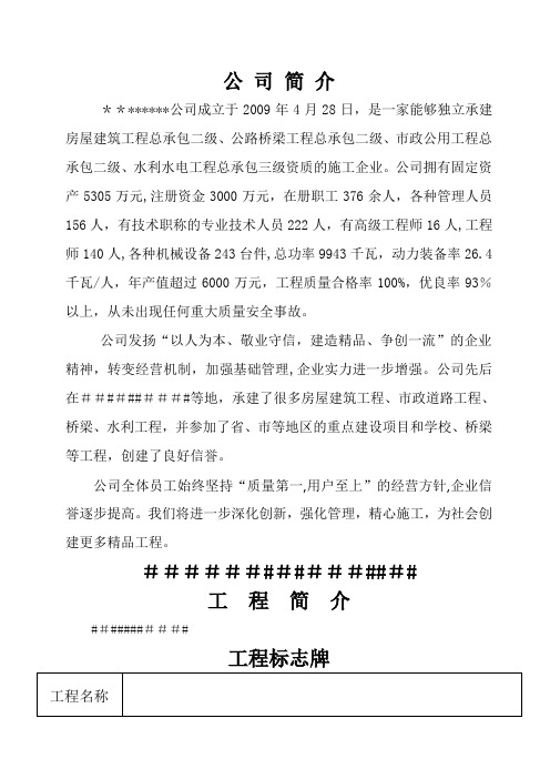
公司简介********公司成立于2009年4月28日,是一家能够独立承建房屋建筑工程总承包二级、公路桥梁工程总承包二级、市政公用工程总承包二级、水利水电工程总承包三级资质的施工企业。
公司拥有固定资产5305万元,注册资金3000万元,在册职工376余人,各种管理人员156人,有技术职称的专业技术人员222人,有高级工程师16人,工程师140人,各种机械设备243台件,总功率9943千瓦,动力装备率26.4千瓦/人,年产值超过6000万元,工程质量合格率100%,优良率93%以上,从未出现任何重大质量安全事故。
公司发扬“以人为本、敬业守信,建造精品、争创一流”的企业精神,转变经营机制,加强基础管理,企业实力进一步增强。
公司先后在##########等地,承建了很多房屋建筑工程、市政道路工程、桥梁、水利工程,并参加了省、市等地区的重点建设项目和学校、桥梁等工程,创建了良好信誉。
公司全体员工始终坚持“质量第一,用户至上”的经营方针,企业信誉逐步提高。
我们将进一步深化创新,强化管理,精心施工,为社会创建更多精品工程。
################工程简介###########工程标志牌项目部组织机构图一、安全控制目标安全总体目标,总的安全事故为“零”,杜绝重大安全事故,减少一般性安全事故,年度轻伤事故率控制在千分之一二、文明施工控制目标实行施工总体控制平面模块管理,做到设施标准,行为规范,施工有序,环境整洁,实现科学管理,文明施工,增创文明工地,树立企业形象三、质量控制目标达到市级优质工程的质量水平,争创精品工程1、分部工程质量合格率100%,单位工程合格率100%2、施工工艺规范、美观、观感率≥95%四、成本控制节约投资,控制造价、精打细算、采取强有力的降效措施,在保证质量的前提下,尽量减少开支,节约成本五、工期控制目标月日前完成所有工程,达到交工条件施工安全十项技术措施1、按规定使用安全“三宝”。
- 1、下载文档前请自行甄别文档内容的完整性,平台不提供额外的编辑、内容补充、找答案等附加服务。
- 2、"仅部分预览"的文档,不可在线预览部分如存在完整性等问题,可反馈申请退款(可完整预览的文档不适用该条件!)。
- 3、如文档侵犯您的权益,请联系客服反馈,我们会尽快为您处理(人工客服工作时间:9:00-18:30)。
安全标志平面布置图
12#楼
通 ○13 ○3 ○9
宣 传 栏
通 ○13 ○3 ○9 6#楼
物料机
○7 ○11
搅拌机 ○4 ○5 ○6
通 沙石 ○123#○楼3 ○9
塔 ○11 ○7 ○8
物料机
○7 ○11
7#楼 8#楼
通 ○13 ○3 ○9 5#楼
配电 ○2房○4
物料机
图例: 通 安全通道
○1 :禁止吸烟 ○2 :禁止烟火 ○3 :注意安全 ○4 :当心触电 ○5 :当心机械伤人 ○6 :当心伤手 ○7 :当心坠落 ○8 :当心落物 ○9 :当心扎脚 ○10 :当心车辆 ○11 :必需戴好安全帽 ○12 :必须系好安全带 ○13 :安全通道 ○14 :安全楼梯
说明: ○14 设在楼梯每层一处 ○9 设在模板拆除区 ○12 设 在 必 须 系 安 全 带 的位置
.
通
○3 ○8 ○11
基坑
塔吊
18#楼
通 ○3 ○8 ○7 ○11 道
塔吊
19#楼
20#楼
○3
○7
○2 ○3 ○4 ○5 ○8
○8
钢筋加工棚
○11
通道
塔
22#楼 吊
21#楼
○2 ○5 ○6 ○8 ○9
木工加工 棚
○5 ○7 ○11 塔
23#楼
图例: 通 安全通道
○1 :禁止吸烟 ○2 :禁止烟火 ○3 :注意安全 ○4 :当心触电 ○5 :当心机械伤人 ○6 :当心伤手 ○7 :当心坠落 ○8 :当心落物 ○9 :当心扎脚 ○10 :当心车辆 ○11 :必需戴好安全帽 ○12 :必须系好安全带 ○13 :安全通道 ○14 :安全楼梯
搅拌机 ○4 ○5 ○6
1#楼
○7 ○11
塔 ○11 ○7 ○8
通 ○13 ○3 ○9
说明: ○14 设在楼梯每层一处 ○9 设在模板拆除区 ○12 设 在 必 须 系 安 全 带 的位置
搅拌机 ○4 ○5 ○6
物料机
○7 ○11
.
.
安全标志平面布置图
钢筋加工棚
塔吊
○2 ○3 ○4 ○5 ○8
○5 ○7 ○11 15#楼
