2018-cad常用图库下载dwg-推荐word版 (1页)
AutoCAD2018实用教程AutoCAD绘图辅助工具

AutoCAD 2018实用教程
3.2.1 缩放和平移视图
按一定的比例、观察位置和角度显示图形的区域称为视图。在 AutoCAD中,可以通过缩放与平移视图来方便地观察图形。
1. 缩放视图 2. 平移视图
AutoCAD 2018实用教程
新建图层 设置图层 图层管理
AutoCAD 2018实用教程
3.1.1 新建图层
在快捷工具栏中选择“显示菜单栏”命令,在弹出的菜单中选择 “格式”|“图层”命令或在“图层”功能区中单击“图层特性”按钮 , 打开“图层特性管理器”选项板。单击“新建图层”按钮 ,在图层列 表中将出现一个名称为“图层1”的新图层。
域。图层的颜色实际上是图层中图形对象的颜色。每个图层都拥有自 己的颜色,对不同的图层可以设置相同的颜色,也可以设置不同的颜 色,当绘制复杂图形时就能够很容易区分图形的各部分。
• “索引颜色”选项卡 • “真彩色”选项卡 • “配色系统”选项卡
AutoCAD 2018实用教程
3.1.2 设置图层
设置图层线型 线型指的是图形基本元素中线条的组成和显示方式,如虚线和实线等。
创建平铺视口
AutoCAD 2018实用教程
3.2.3 使用平铺视口
分割与合并视口
AutoCAD 2018实用教程
3.2.4 使用ShowMotion
在AutoCAD 2018中,可以通过创建视图的快照来观察图形。
AutoCAD 2018实用教程
3.3 栅格和捕捉
“栅格”是一些标定位置的小点,起坐标纸的作用,可以提供直观 的距离和位置参照;“捕捉”用于设置鼠标光标移动的间距。在 AutoCAD中,使用“捕捉”和“栅格”功能,可以提高绘图效率。
(完整word版)AutoCAD2018设置成经典界面与方法
AutoCAD 2018设置成经典界面的方法作者:山水2017-03-26(版权所有,如需转载,请注明出处!)AutoCAD自2009版采用Ribbon功能区后,将经典模式保留到2014版。
用户可以方便地切换ribbon界面和经典界面。
从2015版开始彻底取消了经典模式。
相信不少用户习惯了AutoCAD的经典工作界面,对ribbon方式不太习惯。
通过以下步骤,很快就能自己动手,创建经典工作界面。
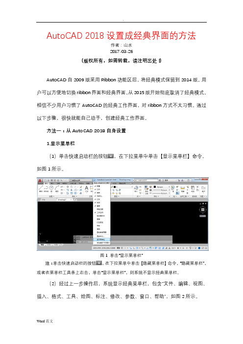
方法一:从AutoCAD 2018自身设置1.显示菜单栏(1)单击快速启动栏的按钮,在下拉菜单中单击【显示菜单栏】命令,如图1所示。
图1 单击“显示菜单栏”注:单击快速启动栏的按钮,在下拉菜单中单击【隐藏菜单栏】命令,“隐藏菜单栏”,或者在菜单栏工具条上右击,单击“显示菜单栏”,则系统不显示经典菜单栏。
(2)经过上一步操作后,系统显示经典菜单栏,包含“文件、编辑、视图、插入、格式、工具、绘图、标注、修改、参数、窗口、帮助”,如图2所示。
图2 显示菜单栏后的界面2.调出工具栏(1)依次单击【工具】|【工具栏】|【AutoCAD】,展开级联菜单,单击【修改】选项,如图3所示。
图3 展开【工具】|【工具栏】|【AutoCAD】|【修改】级联菜单(2)经过上一步操作,传统的“修改”工具栏显示出来。
将光标置于“修改”工具栏,右键单击,如图4所示。
图4 在工具栏上右键单击显示快捷菜单(3)在弹出的快捷菜单中选择“标准”、“特性”、“图层”、“绘图”、“对象捕捉”、“样式”、“标注”、“绘图次序”等选项,显示相应的工具栏。
如图5所示。
图5 调出传统的二维绘图与编辑等工具栏3.切换选项卡、面板标题、面板按钮在选项卡的A360右边的上三角按钮上单击,可以切换“最小化为选项卡”、“最小化为面板标题”、“最小化为面板按钮”,系统并未关闭丝带式菜单。
如图6所示。
单击此按钮切换功能区显示方式图6 切换选项卡、面板标题、面板按钮4.关闭功能区如果感觉【功能区】选项卡“默认、插入、注释、参数化、视图、管理、输出、附加模块、A360”工具条没必要显示,则在该行任意位置右击,弹出快捷菜单,点击【关闭】选项即可,如图7所示。
史上所有版本CAD版本下载地址
史上最全的AutoCAD版本 2004/2005/2006/2007/2008/2009/2010
全部测试可以运行,注册机及破解文件已经打包在一起,需要哪个版本就直接下哪个版本就好了。说没有资源的朋友,请使用电驴进行下载。
AutoCAD 2004
下载地址:ed2k://|file|AutoCAD%202004.rar|322874807|DE9F5419E6F67DAAAE433B3941B49646|h=LRBJOEEABWTNCIWDLWZ5JD2EUFDPIWWX|/
AutoCAD是自动计算机辅助设计软件。是由美国Autodesk公司为计算机上应用CAD技术而开发的绘图程序软件包,现已经成为国际上广为流行的绘图工具。.dwg文件格式成为二维绘图的常用标准格式。
AutoCAD的发展可分为初级阶段、发展阶段、高级发展阶段、完善阶段和进一步完善阶段五个阶段。
初级阶段
Dos版的最高顶峰,具有成熟完备的功能,提供完善的AutoLisp语言进行二次开发,许多机械建筑和电路设计的专业CAD就是在这一版本上开发的。这一版本具有许多即使现在的版本也不具备的特性,例如实体爆炸后得到的是3Dface,而不是像现在版本这样变成面实体——还是实体,不像3Dface那样可以对顶点进行单独拉伸。
AutoCAD 2009
下载地址:ed2k://|file|AutoCAD%202009.rar|1120076216|ACD76BF54C8400214B6B84281CCD7B5D|h=D24J5VNJ6H5P2MJVNLKL5Wed2k://|file|AutoCAD%202010.rar|1988352946|98899186D4FD11BB50EE425FC36473F0|h=J57TV2BERCGEIUILBRYVOAPI4QW62K4R|/
Autodesk AutoCAD 2018.1.1 Update 说明书
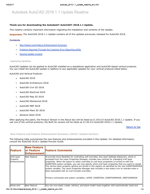
Autodesk AutoCAD 2018.1.1 Update ReadmeThank you for downloading the Autodesk® AutoCAD® 2018.1.1 Update.This readme contains important information regarding the installation and contents of the Update.Important: The AutoCAD 2018.1.1 Update contains all of the updates previously released for AutoCAD 2018.ContentsNew Feature and Feature Enhancement SummaryProblems Reported Through the Customer Error Reporting UtilityGeneral Update ContentApplying UpdatesAutoCAD Updates can be applied to AutoCAD installed as a standalone application and AutoCAD-based vertical products. You can install the AutoCAD update in addition to any applicable updates for your vertical products listed below.AutoCAD and Vertical Products:AutoCAD 2018AutoCAD Architecture 2018AutoCAD Civil 3D 2018AutoCAD Electrical 2018AutoCAD Map 3D 2018AutoCAD Mechanical 2018AutoCAD MEP 2018AutoCAD Plant 3D 2018Advance Steel 2018After applying this patch, the Product Version in the About box will be listed as O.154.0.0 AutoCAD 2018.1.1 Update. If you use one of the vertical products, the Built On version will be listed as O.154.0.0 AutoCAD 2018.1.1 Update.Return to Top New Feature and Feature Enhancement Summary (2018.1 Update Section)The following table summarizes the new features and enhancements provided in this Update. For detailed information, consult the AutoCAD 2018.1 Update Preview Guide.Feature New Featureor FeatureEnhancementFeature CommentsXref Layer Property Enhancements New Feature To provide more flexibility for controlling xref overrides, the Layer Settings dialog box, which is accessed from the Layer Properties Manager, includes new controls for managing Xref layerproperties. When the option to retain overrides to xref layer properties is turned on with theVISRETAIN system variable, you can now specify which xref layer properties that you want to reload.The various layer property options are stored in the registry as specified by the new VISRETAINMODEsystem variable. The Layer Properties Manager also includes a new status icon to indicate when alayer associated with an xref includes overrides.Primary commands and system variables: LAYER, VISRETAIN, VISRETAINMODE, XREFOVERRIDEViews and New Feature You can now easily create, retrieve, and place model views together with automatically sized andViewports scaled layout viewports onto the current layout. When selected, layout viewport objects display twoadditional grips, one for moving the viewport, and the other for setting the display scale from a list ofcommonly used scales.Primary commands and system variables: MVIEW, NEWVIEWHigh resolution (4K) monitor support FeatureEnhancementSupport for high resolution monitors continues to be improved in the Update. More than 200 dialogboxes and other User Interface elements have been updated to ensure a quality viewing experienceon high-resolution (4K) displays.For the best results, use the Windows 10 operating system and a compatible video card.3D Graphics Performance FeatureEnhancementThe 3D graphics performance for the Wireframe, Realistic, and Shaded visual styles continues toincrease depending on the content of the DWG files tested. For example, the median value for theframes-per-second performance in the six large benchmark models used increased by 37% in theUpdate as compared to AutoCAD 2018.Primary commands and system variables: 3DORBIT, ZOOM, PAN, VSCURRENTReturn to TopProblems Reported Through the Customer Error Reporting UtilityAs a result of the detailed information that we received from customers who used the Customer Error Reporting Utility, we were able to identify and fix several defects with the following results:2018.0.1 UpdateGeneralOccasional crashes when ending an AutoCAD session using specific API code no longer occur.2018.0.2 UpdateGeneralOccasional crashes when editing an undefined hatch pattern no longer occur.Occasional crashes when opening certain DXF files no longer occur.2018.1 UpdateGeneralOccasional crashes when switching the visual style to 3D after using the PDFCLIP command no longeroccur.Occasional crashes when right-clicking the drawing from the Start tab no longer occur.Occasional crashes when saving to the AutoCAD 2004/LT 2004 Drawing format or an earlier format nolonger occur.2018.1.1 UpdateGeneralOccasional crashes when opening the block editor no longer occur.Occasional crashes when selecting or creating a non-associative hatch no longer occur.Occasional crashes when clicking the Insert View button on the ribbon in some drawings no longeroccur.Occasional crashes when modifying certain dimension styles no longer occur.Occasional crashes when editing the grip of a spotlight in some drawings no longer occur.Occasional crashes when opening DXF files containing Xrefs no longer occur.Return to Top General Update ContentSeveral additional defects have been fixed with the following results:2018.0.1 UpdateAnnotationPublishing annotative multiline attributes no longer results in incorrect annotative scaling.FontPFB fonts can now be compiled successfully as SHX files.PDFThe border of a mask is no longer plotted in PDFs when, from the Plot dialog box, PDF Options, MergeControl, the Lines Merge option is specified.2018.0.2 UpdateBlockRight-clicking in the Block Editor no longer displays an error message in the Command window.PlotCertain text styles are no longer upside down when printed to PDF.Self-Intersecting wipeouts in a block will perform as expected when plotted.GeneralA defect that would otherwise have caused the product subscription to expire on June 1st, 2017 witha pre-release product error message is fixed.The ability to input values for the Material Editor Palette is restored.Digitally signed AutoLISP files can be loaded as expected.2018.1 UpdateLinetypeThe properties of complex linetypes are now supported by standards files (.dws).GeneralAutoCAD no longer hangs on Windows 10 when copying objects between AutoCAD 2018 and AutoCAD2017.Crossing Window and Fence selection can select objects that are not on the current UCS XY plane.The Digital Signature Warning dialog box does not display on every save or autosave operation.Plot preview performance is improved on some drawings that previously were slower than expected.2018.1.1 UpdateBlocksThe attribute position of a block remains the same after editing the block.PDF/PlotPDF files plotted from certain drawings now display correctly in Adobe Reader.Hatch patterns in PDF files are consistent with lineweight.Raster images are plotted correctly when Shadeplot is set to the Rendered option.GeneralThe AEC property-set data in DWG files can be successfully exported to 3D DWF files.Certain Pro/E files can now be successfully imported into AutoCAD.Return to Top Uninstall This UpdateWindows 7 / Windows 8.1 / Windows 101. Click Start and then Control Panel.2. Click Programs.3. Click Programs and Features.4. In the left pane in the Programs and Features window, click View Installed Updates.5. Find the appropriate update in the list of updates. Click Uninstall.Return to Top Thank YouWe want to express our appreciation to all our customers who identified these issues and reported them to us. Your reports gave us the opportunity to improve the quality of the product. We also thank you for your continued business, and for your valuable feedback regarding this release.Respectfully,The Autodesk AutoCAD Product TeamReturn to Top Copyright ©2017 Autodesk, Inc.。
AutoCAD2018

“特性”工具栏
1.修改颜色
选中要修改的对象后,单击工具栏
,后面的黑三角符号,在颜色选
项窗口中选择所需的颜色,此时对象仍以高亮显示,单击Esc键即可。
AutoCAD 2018 实用教程
2.修改线型
选中要修改的对象后,单击工具栏
“选择线型”对话框
AutoCAD 2018 实用教程
若需要其他线型,必须对线型进行加载,将所需的线型添加到列 表框中。单击对话框中的“加载(L)…”按钮,打开“加载或重载 线型”对话框,
“加载或重载线型”对话框
AutoCAD 2018 实用教程
4.线宽设置
在图层特性管理器对话框的图层列表中单击“线宽”列的“默 认”,打开“线宽”(Lineweight)对话框,选择所需的线宽,然 后单击“确定”按钮即可。
单击“图层特性管理器”对话框中的 (新建特性过滤器(P)(Alt+P))按钮,打开 “图层过滤器特性”对话框过滤图层,来命名图层过滤器。
“图层过滤器特性”对话框
AutoCAD 2018 实用教程
(2)使用新建组过滤器 (New Group Filter)过滤图层 单击“图层特性管理器”对话框中的 (新建组过滤器(G)(Alt+G))按钮,就
剖面线层
轮廓线层
中心线层
图样
AutoCAD 2018 实用教程
4.2 图层设置与管理
“图层特性管理器”(Layer Properties Manager)对话框
命令输入方式 命令行:LAYER 菜单栏:格式→图层 工具栏:图层→ 命令别名:LA
AutoCAD 2018 实用教程
CAD教程最全的最完整的(word文档良心出品)
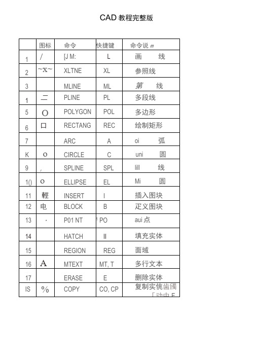
CAD教程完整版好好学吧~学会了都是自己的~~85条高级AutoCAD工程师绘图技巧1. 如何替换找不到的原文字体?复制要替换的字库为将被替换的字库名,女口:打开一幅图,提示未找到字体jd,你想用hztxt.shx 替换它,那么你可以去找AutoCAD字体文件夹(font)把里面的hztxt.shx 复制一份,重新命名为jd.shx, 然后在把XX.shx 放到font 里面,在重新打开此图就可以了。
以后如果你打开的图包含jd 这样你机子里没有的字体,就再也不会不停的要你找字体替换了。
2. 如何删除顽固图层?方法1:将无用的图层关闭,全选,COPY占贴至一新文件中,那些无用的图层就不会贴过来。
如果曾经在这个不要的图层中定义过块,又在另一图层中插入了这个块, 那么这个不要的图层是不能用这种方法删除的。
方法2:选择需要留下的图形,然后选择文件菜单->输出->块文件,这样的块文件就是选中部分的图形了,如果这些图形中没有指定的层,这些层也不会被保存在新的图块图形中。
方法3:打开一个CAD文件,把要删的层先关闭,在图面上只留下你需要的可见图形,点文件- 另存为,确定文件名,在文件类型栏选*DXF格式,在弹出的对话窗口中点工具-选项-DXF选项,再在选择对象处打钩,点确定,接着点保存,就可选择保存对象了,把可见或要用的图形选上就可以确定保存了,完成后退出这个刚保存的文件,再打开来看看,你会发现你不想要的图层不见了。
方法4:用命令laytrans ,可将需删除的图层影射为0 层即可,这个方法可以删除具有实体对象或被其它块嵌套定义的图层。
3. 打开旧图遇到异常错误而中断退出怎么办?新建一个图形文件,而把旧图以图块形式插入即可4. 在AUTOCADS插入EXCEL表格的方法。
复希9 EXCEL中的内容,然后在CAD中点编辑(EDIT)--选择性粘贴(PASTE SPECIA L--AutoCAD 图元-- 确定-- 选择插入点—插入后炸开即可。
AutoCAD2018 命令大全 加 详解
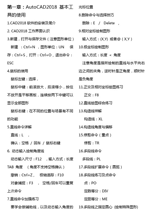
第一章:AutoCAD2018基本工具的使用1.CAD2018软件的安装及简介2. CAD2018工作界面认识3.新建,打开与保存文件(注意图形单位)新建:Ctrl+N ,图形单位:UN 保存:Ctrl+S , 打开:Ctrl+O , 退出命令:ESC4.鼠标的使用鼠标左键:选择,鼠标中键:前滚放大,后滚缩小,按住不放开是平移画板,连续按两下中键可以显示全部图形鼠标右键:在不同的位置与场景有不同的功能5.直线命令详解直线:L ,确认:空格/ 回车/ 鼠标右键6. 动态输入绘制角度线动态输入尺寸:F12 ,输入方式:长度TAB 角度(角度不支持空格确认)撤销:Ctrl+Z , 极轴追踪:F10对象捕捉:F3 ,空格/回车可以重复上次命令7.直线命令加强练习要学会做辅助线,以及动态输入角度的光标位置8.删除命令与选择技巧删除:E / Delete ,9.相对坐标绘制图形输入方式:(X,Y) 或者@(X,Y)10.极坐标绘制图形输入方式:长度< 角度注意角度是指所绘制的直线与水平向右边之间的夹角,逆时针是正角度,顺时针是负角度11.正交及相对坐标绘图练习正交:F812.直线绘图综合练习13.构造线祥解构造线:XL14.构造线角度与偏移15.修剪命令(重点)修剪:TR16.多段线命令多段线:PL17.多段线扩展命令(圆弧)18.多段线练习及点命令点:PO定数等分:DIV定距等分:ME19.多段线之指定圆心(绘制特殊图形)20.圆工具的使用圆:C21.圆工具练习22.圆命令练习(from基点绘制方法)激活绘图命令—from—指定基点--@X,Y (相对坐标)23.圆弧绘制的几种方法圆弧:A 圆弧是逆时针方向绘制的。
24.绘制圆弧的剩余方法(注意优弧与劣弧之分)优弧是指大于180度的弧劣弧是指小于180度的弧25.圆弧绘制练习一(有新知识点)26圆弧练习二27 . 了解CAD2018新功能,安装升级补丁28. CAD2018新功能(PDF导入及增强SHX文字识别等新学员可跳过)29. CAD2018新功能(屏幕外选择,布局视口及智能标注)开启与关闭屏幕外选择的系统变量:SELECTIONOFFSCREEN (0关,1开)30.CAD2018新功能(外部参照功能增强新学员可跳过)更改默认路径:REFPATHTYPE ( 1 相对,2 完整,0 无路径) 第二章:基本绘图操作与修改工具2-1. 绘制矩形的几种方式(上)矩形:REC 尺寸输入方式:X,Y或@X,Y 或X TAB Y 。
CAD2018课件
淘课家园-专注精品高端设计类教程网
专业-实用-易学-完整-超值
淘课家园 AutoCAD 2018 高端精品课 作者:万老师 第一阶段:CAD基础入门篇
第3讲:斜线画法、角度算法、快速标注技法应用
●知识点 1、画斜线公式:@长度<角度 2、矩形:REC 3、旋转:RO 4、偏移:O 5、移动:M 6、修剪:TR回车二次,对准不要的对象直接点
6、shift+6(转化符号)
淘课家园-专注精品高端设计类教程网
专业-实用-易学-完整-超值
淘课家园 AutoCAD 2018 高端精品课 作者:万老师
课程特色:实用-易懂-高效+原创教学思路
第三阶段:CAD精通实战篇
第46讲:打印 命令:CTRL+P 模型空间出图:需要先设页面,然再进入打印设置 打印比例:首先打印比例不是绘图比例。最终打印显示在图纸的与实物之间比例
淘课家园-专注精品高端设计类教程网
专业-实用-易学-完整-超值
淘课家园 AutoCAD 2018 高端精品课 作者:万老师
课程特色:实用-易懂-高效+原创教学思路
第二阶段:CAD绘画进阶篇
第36讲:图案填充应用 命令:H 笔记 1、比例用于修改填充间距 2、角度用于修改填充图形角度;角度是以45度为基础,也就是正常45度为零 度 3、机械、家具,局部,节点,立面,剖面主要用于表达内部结构。 4、建筑、室内、家具等图纸填充图案一般代表材料。
淘课家园-专注精品高端设计类教程网
专业-实用-易学-完整-超值
淘课家园 AutoCAD 2018 高端精品课 作者:万老师
课程特色:实用-易懂-高效+原创教学思路
第二阶段:CAD绘画进阶篇
AutoCAD2018软件安装包下载链接及安装教程
AutoCAD2018软件安装包下载链接及安装教程AutoCAD-2018软件安装步骤1第1步AutoCAD-2018安装包分为32位和64位,下载安装包前,请先查看自己电脑是多少位的操作系统。
首先右击【我的电脑】选择属性2第2步根据下图标记位置查看自己电脑的操作系统,小编电脑为64位的操作系统下载安装包为AutoCAD-2018--64位安装包3第3步下载的软件安装包至安装电脑,右击解压4第4步打开解压出的文件夹【AutoCAD-2018-64位安装包】5第5步双击【AutoCAD2018-64位安装包.exe】运行安装程序,并记住注册机的位置6第6步点击弹出窗口中的【更改】按钮,选择软件安装位置7第7步选择好软件安装位置,然后点击【确定】按钮软件安装位置尽量不要选择安装在C盘8第8步耐心等待5-10分钟9第9步点击【安装】继续安装软件10第10步首先勾选【我接受】,然后点击【下一步】继续安装11第11步点击【浏览】再次选择软件安装位置12第12步选择好软件安装位置后,点击【安装】继续安装软件13第13步耐心等待安装完成(30左右分钟)14第14步点击【完成】按钮,完成初步安装15第15步如果出现提示重启电脑,点击【否】16第16步返回桌面找到AutoCAD-2018图标,并打开软件17第17步选择【输入序列号】18第18步点击【我同意】按钮19第19步点击【激活】按钮20第20步输入序列号:666-69696969,产品秘钥:001J1 然后点击下一步继续安装21第21步然后如果会提示序列号无效,点击【关闭】按钮22第22步再次点击【激活】按钮,如果还是提示序列号无效请重启电脑后断网打开激活23第23步如果需要再次输入序列号,再次输入序列号:666-69696969,产品秘钥:001J1如果不需要跳过此步,直接进行下一步24复制申请号,此窗口不要关闭。
复制采用Ctrl+C的复制快捷键25第25步打开第5步提到的注册机的位置并鼠标右键打开,以管理员身份运行。
2018年专业人士最佳CAD软件
2018年专业人士最佳CAD软件寻找最好的CAD软件?查看我们的2018年买家指南,了解目前市场上最好的专业CAD软件工具。
深入了解CAD软件工具是否适合工作可能是一项繁琐的工作。
考虑到这一点,我们已经在广泛的网络上进行了搜索,因此您无需编辑这些复杂的CAD工具列表。
您可以在下面找到有关兼容文件类型,操作系统,设计模式,顶线功能以及最重要的价格的说明。
最佳CAD软件2018Solidworks操作系统Windows价格12,500美元格式3dxml,3dm,3ds,3mf,amf,dwg,dxf,idf,ifc,obj,pdf,sldprt,stp,STL,vrmlCAD类型2D / 3DSolidWorks是一种在Microsoft Windows上运行的实体建模计算机辅助设计(CAD)和计算机辅助工程(CAE)3D CAD软件。
SolidWorks由DassaultSystèmes开发和发布。
与3DS的其他产品CATIA相比,Solidworks在设计时考虑了更广泛的行业:它应用于工业设计和机械工程等领域。
特别是航空航天,汽车,造船,工业设备,建筑以及医疗和能源部门。
就像其竞争对手Autodesk Inventor一样,这款3D CAD软件也是最好的工业3D建模软件之一。
然而,它不仅需要广泛的培训才能充分发挥其潜力,还需要先进的工程知识。
最佳CAD软件2018CATIA操作系统Windows价格$ 8,500格式化3dxml,catpart,igs,pdf,stp,STL,vrmlCAD类型2D / 3DCATIA是计算机辅助三维交互式应用程序的首字母缩写。
这个多平台应用程序有三个帽子:第一个是3D CAD软件,第二个是计算机辅助制造(CAM)软件,第三个是计算机辅助工程(CAE)软件套件。
CAD软件由法国公司DassaultSystèmes开发。
它应用于工业设计和机械工程等领域。
AutoCAD 2018 for Mac和AutoCAD LT 2018 for Mac预览指南说明
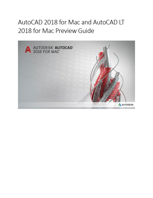
AutoCAD 2018 for Mac and AutoCAD LT 2018 for Mac Preview GuideMigration (3)User Interaction (4)Touch Bar* (4)Tabs for Multiple Palettes (4)Auto-Hide Docked Palettes (4)Icons (4)Off‐screen selection (5)Command Alias Editor (5)Flatten Command (Not available in AutoCAD LT) (6)Plotting (6)Documentation (6)SHX Text Recognition (6)Combine Text (9)External Reference Paths (10)DWG Format Update (10)MigrationSeamlessly migrate your custom files and settings from AutoCAD 2017 for Mac to AutoCAD 2018 for Mac. The migration utility starts automatically when you first open AutoCAD 2018 for Mac.Click View Details to select which files and settings you want to migrate.User InteractionTouch Bar*Support for the Apple touch bar has been added. While you are using AutoCAD for Mac, the Touch Bar displays icons for function key shortcuts.Note: Press fn to revert to the standard F1-F12 function keys.You can customize the touch bar by clicking View menu > Customize Touch Bar.Tabs for Multiple PalettesTo make it easier to keep multiple palettes open without using valuable screen space, some of the palettes can be docked and are organized using tabs when docked.Auto-Hide Docked PalettesYou can now auto-hide your docked palettes to increase your drawing area. Click where indicated to set the docked palettes to auto-hide.The palette title bars remain visible. If you have multiple tabs for the palettes there is a title bar for each tab. Mouse over the title bar for the palette you want to show, and the palette automatically expands. IconsIcons have been updated for a clean, modern look. Some examples:Off‐screen selectionYou can begin a selection window in one part of your drawing and then pan and zoom to another part while maintaining selection of the off-screen objects. You can control the behavior of off-screen selection using the SELECTIONOFFSCREEN system variable.Command Alias EditorCommand aliases are shortened command names that can be entered at the Command prompt as an alternative to the standard full command name and are stored in a program parameter (PGP) file. Previously, the command aliases were edited using a text editor, but for AutoCAD 2018, a new tab has been added to the Customize dialog making it easy to edit, add, and remove command aliases.Flatten Command (Not available in AutoCAD LT)A new command, FLATTEN, is available. FLATTEN creates a 2D representation of selected objects and projects them onto the current viewing plane. FLATTEN results in 2D objects that retain their original layers, linetypes, colors, and object types where possible. You can use FLATTEN to create a 2D drawing from a 3D model, or you can use it to force the thickness and elevations of selected objects to 0.PlottingThe Plot dialog box contains the following updates:∙Directly modify all plot settings including paper size, scale, offset, plot stamp, and more∙Switch, save, or import a page setup∙"None" printer support∙PDF plotters support∙Inherit the paper size information from the drawing∙Apply the current plot settings to the active layoutDocumentationPDF files are the most common file format used when exchanging design information between designers, contractors, clients, and others. AutoCAD 2017 for Mac introduced the ability to import PDF files. The PDFIMPORT command imports PDF data into AutoCAD as 2D geometry, TrueType text, and images.SHX Text RecognitionAdobe’s PDF file format doesn’t recognize Au toCAD SHX fonts, therefore, when a PDF file is created from a drawing, text that was defined with SHX fonts is stored in the PDF as geometry. If that PDF file is then imported into a DWG file, the original SHX text is imported as geometry.AutoCAD 2018 for Mac offers a SHX text recognition tool that enables you to select imported PDF geometry representing SHX text and convert it to text objects. Access this functionality from the Recognize SHX Text tool (PDFSHXTEXT command) on the Text panel on the tool sets.The SHX recognition tool analyzes clusters of geometry (i.e., lines, polylines, etc.) from your selection set and compares them to characters in specified SHX cache files.A Settings option is available to help you manage which SHX fonts you’d lik e to compare against the selected text, as well as to control some settings during the conversion. The most common SHX fonts are listed by default, and you can then add or remove SHX fonts based on your needs, and select which fonts in the list you want to compare against the selected text.AutoCAD compares each of the selected fonts in order until one is found that matches the selected text within the specified recognition threshold. An option to use the best matching font ensures that AutoCAD compares the text to all of the selected fonts, and chooses the best one.After comparing the geometry to the SHX fonts, the geometry that matches is automatically replaced with one or more Mtext objects. A message box will display the results.Combine TextThe Combine Text tool enables you to combine many individual text objects into one multi-line text object. This can be particularly useful after recognizing and converting SHX text from an imported PDF file. You can access the Combine Text tool (TXT2MTXT command) from the Text panel on the tool sets.A Settings option on the Command Line displays the Text to MText Settings dialog.External Reference PathsThe default path type for external references is now set to Relative. Additional capabilities include the following:∙Right-click to use the new Select New Path option. When you fix the path for a missing external reference, you can now apply the same path for other missing reference files.∙When you save the host drawing in a new location, you are prompted to update the relative paths for the external references.∙You can attach references with Relative Path type in unnamed files.If Relative path isn’t your preferred path type, you can use the new REFPATHTYPE system variable to modify the default reference path type. Set the value to 0 for No path, 1 for Relative path, or 2 for Full path.DWG Format UpdateThe DWG format for all AutoCAD-based products has been updated to the 2018 version. When saving files back to previous versions of an AutoCAD DWG format, certain data may be ignored and will not be accessible by earlier versions of the software.。
2018-cad坐标设置快捷键-推荐word版 (18页)
本文部分内容来自网络整理,本司不为其真实性负责,如有异议或侵权请及时联系,本司将立即删除!== 本文为word格式,下载后可方便编辑和修改! ==cad坐标设置快捷键篇一:cad坐标归零CAD Z轴坐标归零请按步骤操作1.将画面ctrl+a全选2.使用移动(m_)命令,输入第一点位置0,0,0 确定,然后输入第二点位置0,0,1e99(是数字一英语字母E和数字九九)确定3.将画面ctrl+a全选4.使用移动(m_)命令,输入第一点位置0,0,1e99 确定,然后输入第二点位置0,0,-1e99确定5.使用移动(m_)命令,输入第一点位置0,0,-1e99 确定,然后输入第二点位置0,0,0确定这样Z轴就归零了,原理是将问题的点全部移至正无穷,再移至负无穷,最后再移回到0坐标注意:在这样做之前,要将块先打散,不然即使按部就班的做了这些步骤,图形也回不到0坐标篇二:十分全面的CAD快捷键(还教你如何自己设置自己喜欢的快捷键)CAD快捷键一览创建三维阵列 3A创建三维面 3F在三维空间创建由直线段组成的多段线 3P在二维和三维空间中将某对象与其他对象对齐 AL加载 AutoLISP、ADS 和 ARX 应用程序 AP创建圆弧 A计算对象或定义区域的面积和周长 AA创建按指定方式排列的多重对象拷贝 AR执行外部数据库命令的管理功能 AAD输出选择对象的链接信息 AEX管理对象和外部数据库之间的链接 ALI显示并编辑表数据并创建链接和选择集 ARO从链接到文字选择集和图形选择集的行中创建选择集 ASE 执行结构查询语言 (SQL) 语句 ASQ创建属性定义 -AT改变不依赖于块定义的属性信息 -ATE用图案填充封闭区域 H或BH根据选定对象创建块定义 -B用对话框定义块 B用封闭区域创建面域或多段线 BO(使用命令行)用封闭区域创建面域或多段线 -BO部分删除对象或把对象分解为两部分 BR给对象加倒角 CHA修改现有对象的特性 -CH根据圆心和直径或半径绘制圆 C复制对象 CO或CP创建属性定义 AT编辑单个块的可变属性 ATE修改对象的颜色、图层、线型和厚度 CH设置新对象的颜色 COL编辑文字和属性定义 ED显示夹点并设置颜色 GR创建并修改标注样式 D插入块或另一图形 I控制现有对象的特性 MO修改对象名称 REN设置绘图辅助工具 RM设置对象选择模式 SE管理已定义的用户坐标系 UC选择预置用户坐标系 UCP控制坐标和角度的显示格式及精度 UN创建和恢复视图 V设置三维观察方向 VP创建对齐线性标注 DAL或DIMALI创建角度标注 DAN或DIMANG从前一个或选择的标注的第一尺寸界线处连续标注 DBA或DIMBASE 创建圆和圆弧的圆心标记或中心线 DCE从前一个或选择的标注的第二尺寸界线处连续标注 DCO或DIMCONT 创建圆和圆弧的直径标注 DDI或 DIMDIA编辑标注 DED或DIMED创建线性尺寸标注 DLI或DIMLIN创建坐标点标注 DOR或DIMORD替换标注系统变量 DOV或DIMOVER创建圆和圆弧的半径尺寸标注 DRA或DIMRAD在命令行创建和修改标注样式 DST或DIMSTY移动和旋转标注文字 DIMTED测量两点之间的距离和角度 DI将点对象或块沿对象的长度或周长等间隔排列 DIV 绘制填充的圆和环 DO修改图像和其他对象的显示顺序 DR打开鸟瞰视图窗口 AV输入文字时在屏幕上显示 DT定义平行投影或透视视图 DV创建椭圆或椭圆弧 EL从图形删除对象 E将组合对象分解为对象组件 X以其他文件格式保存对象 EXP延伸对象到另一对象 EX通过拉伸现有二维对象来创建三维实体 EXT给对象加圆角 F创建根据特性选择有关对象时用到的过滤器列表 FI 创建对象的命名选择集 G使用命令行创建选择集 -G用图案填充一块指定边界的区域 -H修改现有的图案填充对象 HE重生成三维模型时不显示隐藏线 HI。
- 1、下载文档前请自行甄别文档内容的完整性,平台不提供额外的编辑、内容补充、找答案等附加服务。
- 2、"仅部分预览"的文档,不可在线预览部分如存在完整性等问题,可反馈申请退款(可完整预览的文档不适用该条件!)。
- 3、如文档侵犯您的权益,请联系客服反馈,我们会尽快为您处理(人工客服工作时间:9:00-18:30)。
2018-cad常用图库下载dwg-推荐word版
本文部分内容来自网络整理,本司不为其真实性负责,如有异议或侵权请及时联系,本司将立即删除!
== 本文为word格式,下载后可方便编辑和修改! ==
cad常用图库下载dwg
篇一:CAD平面图库--厨房用品
篇二:cad图集
篇三:CAD工艺流程图常用图形符号
CAD工艺流程图用图形符号。
3.3.7 常用阀门与管路连接方式的图形符合宜符合表3.3.7的规定。
3.3.8 常用管道支
座、管架和支吊架图形符号宜符合表3.3.8的规定。
3.3.8 常用管道支座、管架和支吊架图形符号宜符合表3.3.8的规定。
3.3.9 常用检测、计量仪表的图形符号宜符合表3.3.9的规定。
3.3.10 用户工程的常用设备图形符号宜符合表3.3.10的规定。
