上海CPC导轨介绍
关于PMI、SME、SMR直线导轨的详细介绍
关于PMI、SME、SMR直线导轨的详细介绍PMI直线导轨、线性滑轨:PMI直线导轨、线性滑轨采用4列圆弧接触式及45°触角的钢珠列设计,提供径向、反径向及横方向四方向的相同额定负荷能力,无论X、Y、Z等轴的各种安装方式都可以使用,并且可在维持低摩擦阻力情况下均匀的施以预压,增强四个受力方向的刚性,特别适合高精度与高负荷的运动方式。
专利的润滑油路设计,能够均匀的将润滑油脂注入每个循环回路,无论各种安装方式都可以获得最佳的润滑效果,并且提升整体的行走顺畅度与使用寿命,实现高精度、高可靠度及平滑稳定的直线运动需求。
PMI微小型直线导轨、线性滑轨(MSC不锈钢系列)产品特性:MSC不锈钢系列直线导轨、线性滑轨采用2列歌德圆弧接触式及45度接触角的钢珠设计,提供径向、反径向及横方向四方向的相同额定负荷能力,无论X、Y、Z等轴的各种安装方式都可以用。
超小型化与低摩擦阻力的设计,适合小型化设备使用。
1、四方向等负荷设计:采用2列歌德圆弧接触式及45度接触角的钢珠设计,提供径向、反径向及横方向四方向的相同额定负荷能力,适合各种安装方式的应用。
2、行走顺畅度佳,低噪音:简单圆滑的钢珠回流路径设计,并采用耐冲击的强化合成树脂之钢珠循环配件,运转顺畅度佳,噪音度低。
3、超小型设计:超小型化设计提供小型化设备于有限空间内的最佳选择。
4、钢珠保挂器设计:具有钢珠保持器设计,可有效防止钢珠不当脱落。
5、具互换之特性:在严密制造精度管控下,尺寸能够维持在稳定的公差内,所以对于互换型直线导轨、线性滑轨,组装时可将滑块任意配装在同型号的滑轨上,并且保持其相同的顺畅度、预压及精度,组装与维修最容易。
SME滚珠保持器型直线导轨、线性滑轨:SME滚珠保持器形直线导轨、线性滑轨比起一般标准型直线导轨、线性滑轨,搭配滚珠保持器的专利设计,可使其运行更为稳定顺畅,特别适用于要求高速度,高精度的设备需求。
四方向负荷最佳化设计:透过结构压力分析,最佳化的四列式滚珠45度圆弧接触角与高刚性断面设计,除了提供径向,反径向及横方向优良的负荷能力,并且可利用预压调整增加其刚性,更适合各种安装方式应用。
顺义CPC直线导轨的选型及安装方法
顺义CPC直线导轨的选型及安装方法CPC微型导轨选型第一步---确定轨宽轨宽指滑轨的宽度。
轨宽是决定其负载大小的关键因素之一,四排滚珠(也有部分两排珠的)的方轨现货产品一般有15、20、25(23)、30(28)、35(34)、45、55(53)、65(63),某些品牌最大只生产到45规格,有些小厂家可能只到30。
期货产品也有85、120等,但大部分厂家不生产。
扁轨(微型滑轨,基本是两排滚珠)规格有3、5、7、9、12、15,上述6个规格又各有一个宽型规格(滑轨宽度是标准型的2倍,其中15型滑轨的安装孔是2列),一共12种,但是有些厂家不能生产7以下的型号,具体请咨询该品牌供应商。
注:()中是实际轨宽。
导轨选型第二步---确定轨长这个长度是轨的总长,不是行程。
全长=有效行程+滑块间距(2个以上滑块)+滑块长度×滑块数量+两端的安全行程,如果增加了防护罩,需要加上两端防护罩的压缩长度。
需要注意的是,事先问清楚该品牌该规格导轨整支的最大长度,超过这个长度是需要对接使用的。
多数厂家整支长度最大是4000(微轨一般是1000),有些是3000,这和厂家的加工设备有关。
需要对接并且用户想事先在机器上加工安装孔的情况下最好提供接口图纸。
另一点请特别注意,导轨上的安装孔孔间距是固定的,用户在确定轨长时要注意位置,例:15的轨,长600。
如果不告诉供应商需要的端部尺寸,一般到货的状态是10个安装孔,导轨两端面到各自最近的安装孔中心的距离是30、30,但也有可能是其他尺寸。
各品牌对端部尺寸的出货规定略有差异,多数是默认两端相等。
还有一点,导轨的长度误差,一般品牌默认2000以下±1~2mm,2000~4000的±2~3mm,如果用户要求比较精确,最好在订购合同上注明误差值或提供图纸。
这种情况供应商可能会收取附加加工费。
导轨选型第三步---确定滑块类型和数量常用的滑块是两种:法兰型,方形。
cpc导轨直线运动系统组成要素
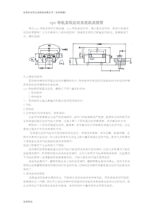
东莞市安昂五金机电有限公司(安昂商城)cpc导轨直线运动系统组成要素用过cpc导轨的朋友们都知道,cpc导轨在运行时,是以直线运动的,那我们知道它运动的原理吗?以及它是有什么部件组成的?相信很多朋友们都曾经好奇过。
答案就在下文,精彩继续!什么是驱动部件:驱动部件提供机构直线运动所需要的动力,导向部件则保证机构在确定的方向运动并提供足够的运动精度和支承刚度。
cpc导轨要实现直线运动,需要以下两个基本的条件:1.驱动部件2.导向部件一.驱动部件工程上最基本的直线运动驱动部件为:1.气缸2.液压缸3.各种电机(如步进电机、伺服电机)这些元件都是商业化生产的标准部件,由专门的制造商生产制造,直接通过采购就可封各种典型的直线运动气缸以获得。
这里分享一个驱动直线运动最简单、成本最低的办法。
要驱动一个机构实现直线运动,最简单、成本最低的办法就是采用直线运动气缸,这也是在工程设计中优先考虑的方法。
采用直线运动气缸作为驱动部件的优点为:安装结构简单、成本低廉、制造快捷,正因为它具有这些优点。
所以在各种自动化设备上都大量采用直线运动气缸。
虽然大多数情况下使用直线运动气缸都能够满足使用要求。
但在少数情况下也会受到以下限制:运动模式的限制普通直线运动气缸只能在两点间进行运动循环,这在大多数情况下都已经能满足要求,即使要实现三点间的运动循环,也可以将两只气缸串联起来使用.这些情况下气缸的速度一旦调整完成后就是固定的,只能以固定的行程及速度运动。
但在有些情况下,需要实现多点之间的运动循环,需要频繁地启动与停止,运动方向与速度也经常需要根据实际情况进行灵活的改变,这样的运动模式用普通直线运动气缸就无法完成了。
4.结构空间的限制.在某些结构非常紧凑的场合,可能缺乏足够的空间来安装气缸,而采用电机则可能很容易解决这一问题。
因为可以通过皮带传动或链传动将电机安装在其他空间允许的地方,因此这种场合下就体现出电机的优越性。
自动机械中大量采用的各种驱动电机。
分析CPC直线导轨设计及其导轨精度注意事项

分析CPC直线导轨设计及其导轨精度注意事项今天我们分析下CPC直线导轨的设计及其导轨精度的注意事项。
一、CPC直线导轨的设计:1、进行CPC直线导轨的力学计算,确定结构尺寸。
2、根据CPC导轨工作条件、承载特性,要选择导轨的结构类型、截面形状以及组合的形式。
3、要确定导轨副的间隙、公差以及加工精度。
4、选择导轨材料、摩擦面硬度匹配和表面精加工还有热处理的方法。
6、选择适合导轨的润滑方式,设计润滑系统和防护装置。
5、选择导轨面磨损后的补偿方式和调整装置。
7、要选择导轨的预紧载荷,还要设计预紧载荷的加载方法与装置。
二、CPC直线导轨的精度要求:1、精度保持性:精度保持性是指导轨工作过程中保持原有几何精度的能力。
导轨的精度保持性主要取决于导轨的耐磨性极其尺寸稳定性。
耐磨性与导轨副的材料匹配、受力、加工精度、润滑方式和防护装置的性能的因素有关,另外,导轨及其支承件内的残余应力也会影响导轨的精度保持性。
2、抗振性与稳定性:抗振性是指导轨副承受受迫振动和冲击的能力,而稳定性是指在给定的运转条件下不出现自激振动的性能。
3、导向精度:导向精度是指运动构件沿导轨导面运动时其运动轨迹的准确程度。
影响导向精度的主要因素有导轨承导面的几何精度、导轨的结构类型、导轨副的接触精度、表面粗糙度、导轨和支承件的刚度、导轨副的油膜厚度及油膜刚度,以及导轨和支承件的热变形等。
直线运动导轨的几何精度一般包括:垂直平面和水平平面内的直线度;两条导轨面间的平行度。
导轨几何精度可以用导轨全长上的误差或单位长度上的误差表示。
4、运动灵敏度和定位精度:运动灵敏度是指运动构件能实现的最小行程;定位精度是指运动构件能按要求停止在指定位置的能力。
运动灵敏度和定位精度与导轨类型、摩擦特性、运动速度、传动刚度、运动构件质量等因素有关。
5、刚度:直线导轨抵抗受力变形的能力。
变形将影响构件之间的相对位置和导向精度,这对于精密机械与仪器尤为重要。
导轨变形包括导轨本体变形导轨副接触变形,两者均应考虑。
CPC导轨与抽屉的作用以及润滑油的作用

CPC导轨与抽屉的作用以及润滑油的作用一、抽屉滑轨应选CPC线性滑轨在很多的家庭中,抽屉是对衣物或者其他的物品收藏放置的地方,其起到了特别便利的作用。
并且在很多的家中抽屉还起侧紧要的装饰作用的,不同的抽屉要装配不同的抽屉滑轨,也因此在快捷性上也是有很大区分的,但是在大家选择滑轨的时候,肯定要考虑很多方面的因素,比如说抽屉或者橱柜的厚度,高度,以及是否采纳比较高档的抽屉滑轨来装饰抽屉等等。
在每个家庭中都有大量的抽屉,大量的橱柜门,因而对于一个家庭来说选择一个抽屉滑轨是特别紧要的,由于选择一个好的抽屉滑轨才能达到一按即开,轻推就会做到闭合的效果,并且可以有效的释放双手操作带来的不便。
通常居民都会选择二节反弹抽屉滑轨或者三节反弹抽屉滑轨。
这两种滑轨相比的话,二节反弹滑轨使用的用户数量比较大。
1、在你想要选择滑轨的时候,应依据不同地区不同生活的消费习惯来选择,或者是橱柜或者门体的应用性能来选择。
反弹抽屉式的滑轨这种叫法在不同的地区都有被不同的叫法,有的称之为推弹滑轨、按1压式自动滑轨、自回弹滑轨等。
2、在你确定了采纳几节反弹滑轨之后,就需要确认选用那种抽屉滑轨的尺寸、相应滑轨的长度、加工好抽屉之后。
正在安装抽屉滑轨时,应当保留在滑轨上有4毫米以上的弹压空间,从而来实现滑轨的一按就开的可能,一推就闭合的效果。
其次是把抽屉放在滑轨上,扣上白色的塑料锁紧钉之后隐匿式反弹簧抽屉滑轨就可以顺当安装完成了。
3、在抽屉进行拆卸的时候,只需要将锁紧钉用力的抽出,就可以很好的实现抽屉和滑轨之间有效的分别,因此特别的便利。
温馨提示:(除以上因素外还有一个最紧要的因素:就是在选择时,适当的考虑到商家的信誉度,商家的口碑,商家的服务态度等等。
假如注意好了这些,在以后显现问题之后,联系商家,才可以在很多的时间内,帮忙你来解决抽屉滑轨碰到的问题。
同时CPC导轨也是个不错的选择)二、导轨油在CPC导轨中可以起到什么作用导轨油适用于自身或带有导轨装置的机械设备,也特别适合那些自身液压系统和其他机械组件一同建在一起的设备,也很适合用于液压电梯和升降机等。
cpc直线导轨HR系列资料

CPC直线导轨AR/HR系列什么是CPC直线导轨?CPC直线导轨为一种滚动导引,借由钢珠在滑块与滑轨之间作无限滚动循环,负载平台能沿着滑轨轻易地以高精度作线性运动。
再加上滑块与滑轨间的束制单元设计,使得CPC直线导轨可同时承受上下左右等各方向的负荷,上述陈列特点并非传统滑动导引所能比拟,因此机台若能配合滚珠螺杆,使用CPC直线导轨作导引,必能大幅提高设备精度与机械效能。
与传统的滑动导引相较,滚动导引的摩擦系数可降低至原来的1/50,由于起动的摩擦力大大减少,相对的较少无效运动发生,故能轻易达到μm级进给及定位。
主要有什么特点呢?1. 磨耗少能长时间维持精度传统的滑动导引,无可避免的会因油膜逆流作用造成平台运动精度不良,且因运动时润滑不充份,导致运行轨道接触面的磨损,严重影响精度。
而滚动导引的磨耗非常小,故机台能长时间维持精度。
2. 定位精度高使用CPC直线导轨作为线性导引时,由于CPC直线导轨的摩擦方式为滚动摩擦,不仅摩擦系数降低至滑动导引的1/50,动摩擦力与静摩擦力的差距亦变得很小。
因此当床台运行时,不会有打滑的现象发生,可达到μm级的定位精度。
3. 可同时承受上下左右方向的负荷由于CPC直线导轨特殊的束制结构设计,可同时承受上、下、左、右方向的负荷,不像滑动导引在平行接触面方向可承受的侧向负荷较轻,易造成机台运行精度不良。
4. 适用高速运动且大幅降低机台所需驱动马力由于CPC直线导轨移动时摩擦力非常小,只需较小动力便能让床台运行,尤其是在床台的工作方式为经常性往返运行时,更能明显降低机台电力损耗量。
且因其摩擦产生的热较小,可适用于高速运行。
5. 组装容易并具互换性组装时只要铣削或研磨床台上滑轨之装配面,并依建议之步骤将滑轨、滑块分别以特定扭力固定于机台上,即能重现加工时的高精密度。
传统的滑动导引,则须对运行轨道加以铲花既费事又费时,且一旦机台精度不良,又必需再铲花一次。
CPC直线导轨具有互换性,可分别更换滑块或滑轨甚至是CPC直线导轨组,机台即可重新获得高精密度的导引。
CPC直线导轨
潤滑油 11 適合一般用途,ISO V32~68
潤滑劑容量:10ml
11
MR 微型滾珠線性滑軌系列
2. 技術資料
2.4 摩擦阻力 摩擦阻力
MR微型滾珠線性滑軌系列其運轉摩擦力平穩 一致,且起動摩擦力輕微,充分展現產品低摩 擦阻力之特性。
摩擦力
Frn= μ F F Frn
(1) 負荷 (N) 摩擦力 (N)
適用於 : 高速皮帶驅動機構 高速移載設計使用 站與站之間自動化連結使用
迴流道特殊設計
鋼珠迴流孔及迴流道由全密式塑膠框架及塑 膠端蓋構成,結構簡單,可大幅減少鋼珠與 金屬的接觸面積及碰撞機會,有效的達到低 噪音運行效果。迴流道內藏特殊設計之儲油 讓槽,可延長潤滑週期。
04
MR 微 型 滾 珠 線 性 滑 軌 系 列
■ 降低摩擦力 ■ 使磨耗減至最少
■ 防止腐蝕現象 ■ 散發熱量並提高運轉壽命至材料疲乏
潤滑方式及注意事項
■ 滑座與滑軌於第一次使用前必須先添加潤滑油加以保護,並避免接觸任何液態或固態污染物。 ■ 在加注潤滑油時,滑座必須以一邊前後來回運動,一邊加油方式進行。 ■ 一般微型線性滑軌潤滑方式可用手或自動潤滑方式直接對滑道做潤滑工作。
嵌入式及倒扣設計
03
MR 微型滾珠線性滑軌系列
1. 產品介紹 1.2 全新設計
塑膠件倒扣設計強化結合機構
可承受更高的運行速度設計;當滑塊運行時,其塑 膠端蓋不斷承受鋼珠循環迴流轉向時所產生的衝擊 力,且運行速度越快其衝擊力越大;在考量自動化
設計高速運行場合需求愈來愈多,因此cpc於 9W、
12M/W、15M/W 等微型系列產品設計了塑膠件倒鈎 設計來強化結合機構。
07
2.2 預壓
cpc导轨
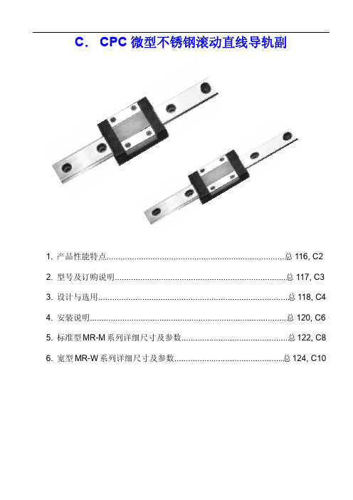
C. CPC微型不锈钢滚动直线导轨副1. 产品性能特点.............................................................................总116, C22. 型号及订购说明..........................................................................总117, C33. 设计与选用..................................................................................总118, C44. 安装说明.....................................................................................总120, C65. 标准型MR-M系列详细尺寸及参数..............................................总122, C86. 宽型MR-W系列详细尺寸及参数...............................................总124, C101. 产品性能特点●高载荷,高扭矩功能MR微型不锈钢滚动直线导轨系列采用二列式滚珠循环设计, 滚珠槽取接触角为45度的哥德式结构, 能实现四向等载荷; 在有效空间限制下,使用了较大直径的钢珠, 从而实现了高载荷、高扭矩功能。
●嵌入式设计滑块金属部分与框架、端盖及密封片之间采用嵌入式设计,免螺钉紧固,从而大大缩小了整个滑块的外形尺寸。
●防尘设计薄型底面密封及端面密封构成全密闭防尘设计;可弹性搭配。
●回流孔特殊设计滚珠回流孔及返向器由全封闭式塑胶框架及塑胶端盖构成,可实现滚珠更平稳地循环,减低噪音。
●保持架设计使用高刚性滚珠保持架,确保滑块拆卸时不会掉珠。
简介CPC直线导轨滑块的知识

东莞市安昂五金机电有限公司(安昂商城)安昂传动传动世界简介CPC直线导轨滑块的知识CPC直线导轨是用于直线往复场合,拥有比直线轴承更高的额定负载,同时,直线导轨是一种滚动导轨,可以借由钢珠在滑块与导轨之间做无限滑动循环,同时可以承担一定的扭矩。
滑块-使运动由曲线转变为直线。
新的导轨系统使机床可获得快速进给速度,在主轴转速相同的情况下,快速进给是直线导轨的特点。
直线导轨与平面导轨一样,有两个基本元件;一个作为导向的为固定元件,另一个是移动元件。
由于直线导轨是标准部件,对机床制造厂来说.唯一要做的只是加工一个安装导轨的平面和校调导轨的平行度。
负载平台能沿着导轨轻易地以高精度作线性运动。
与传统的滑动导引相比较,滚动导引的摩擦系数可降低至原来的1/50,由于启动地摩擦力大大减少,相对的较少无效运动发生,故能轻易达到μm级进给及定位。
再加上滑块与导轨间的束制单元设计,使得直线导轨可同时承受上下左右等各方向的负荷,上述陈列特点并非传统滑动导引所能比拟,因此机台若能派和滚珠螺杆,使用直线导轨作导引,必能大幅提高设备精度与机械效能。
控制装置先在两个垂直方向上建立直线导轨的修正模型,各以面上测量点连接成连续曲线,统计出直线导轨上的所有曲线,并依据曲线段的曲率确定正曲面压入点、负曲面二支撑点的位置坐标及各曲线段的先后冲压次序,在设定所述校正压头及二支撑件的最大修正量后,驱动二支撑件分别顶靠在选定曲线段的负曲面二支撑点上,使校正压头冲压选定曲线段的正曲面压入点以进行校直作业,并将直线导轨的修正模型、最大修正量以及校直日志,以便对较次优先级的曲线段进行校直时做行程补偿变量及数据修正,以对直线导轨进行高精度和高效率的校直.在导轨的行业中现在出现很多的生产厂家,在这些生产厂和贸易厂当中安昂的导轨品牌口碑还是比较好的,所以无论是导轨滑块还是其他的一些机械的知识,安昂专业技术师会一直为大家推送这些专业的,为广大用户朋友提供便利。
讲解CPC直线导轨滑块的珠子脱落的预防及安装
安昂传动
讲解CPC直线导轨滑块的珠子脱落的预防及安装
我们现在运用到CPC直线导轨的场合也会是特别多的,好多的机械当中都有运用到的,所以说在运用当中不免会出现一些故障,那么如何去解救呢?我们来讲解如果CPC直线导轨滑块的珠子脱落的话怎样预防和安装。
其实,在我们解决上银导轨滑块脱落的原因之前,我们可以想象一下发生这个的根源是什么,首先我们要知道的是安装导轨滑块的工作人员是否对安装方法有一定的了解,如果不了解,我们先从这个方面来着手,就会大大的预防导轨滑块脱落出来。
另外,我们可以使用防粘胶粘在滑轨的两面,这样我们在使用时不容易脱落。
我们还可以到市场上买哪种橡胶皮带,穿在滑轨孔的两端(在不影响导轨使用的情况下)。
其实避免CPC直线导轨滑块脱落的原因有很多,看的多了做的多了就慢慢的会学会很多,我们平时也会积累不少这方面的知识慢慢的也会熟悉起来。
这样,我们积累的方法越多对于上银导轨故障的情况也会越来越少,滑块脱落的情况就会出现的越来越少。
安昂传动。
CPC直线导轨LWL系列

IKO直线导轨L微型系列采用两列钢球与轨道4点接触结构。
虽然形状很小,却能在承受方向和大小改变的负荷和复合负荷时,依然保持稳定的精度和刚性。
产品形状和尺寸系列丰富齐备,可根据用途选择适合的型号。
IKO微型直线导轨的特点如下:一、自由组合:滑块的滚珠装有钢球保持器。
即便将滑块从滑轨取下,钢球也不会脱落,易于装配。
滑块和导轨分别进行管理,各自均可自由更换组合,节约成本。
二、材料有不锈钢和碳素钢可选择:不锈钢制产品具有出色的耐腐蚀性,最适合用于讨厌油脂、需要控制防锈油的地方,及洁净室使用。
碳素钢产品广泛应用于搬运和组装装置等通用用途。
三、产品体系多样:拥有世界最小的1mm的标准型(LWL)和力矩大、能够单列使用的宽幅型(LWLF)两种形状的滑轨;滑块有标准、短、高刚性加长三种不同长度的类型;还有滑轨加工成内螺纹的规格满足不同安装方向的选择。
系列产品型号如下:标准型(LWL):LWL1,LWL1Y,LWL2,LWLC3,LWL3,LWLC5B,LWLC5N,LWL5B,LWL5N,LWL5,LWLC7B,LWLC7N,LWL7B,LWL7N,LWL7,LWLG7B,LWLG7N,LWLC9B,LWLC9N,LWL9B,LWL9BCS,LWL9N,LWL9,LWLG9B,LWLG9N,LWLC12B,LWL12B,LWL12BCS,LWL12,LWLG12B,LWLC15B,LWL15B,LWL15BCS,LWL15,LWLG15B,LWLC20B,LWL20B,LWL20BCS,LWLG20B,LWLC25B,LWL25B,LWLG25B;宽幅型(LWLF):LWLF4,LWLFC6,LWLFC6N,LWLF6,LWLF6N,LWLFC10B,LWLFC10N,LWLF10B,LWLF10N,LWLFC14B,LWLFC14N,LWLF14B,LWLF14N,LWLF14,LWLFG14B,LWLFG14N,LWLFC18B,LWLFC18N,LWLF18B,LWLF18BCS,LWLF18N,LWLF18,LWLFG18B,LWLFG18N,LWLFC24B,LWLF24B,LWLF24BCS,LWLF24,LWLFG24B,LWLFC30B,LWLF30B,LWLF30BCS,LWLFG30B,LWLFC42B,LWLF42B,LWLF42BCS,LWLF42,LWLFG42B;IKO直线导轨的特点:•能够高精度定位、静摩擦(起动摩擦)与动摩擦的差小;•能够承受复合负荷,总体平衡出色,使用方便;•产品规格丰富,从世界上最小的1mm到具有超高刚性和承载能力的大型圆柱滚子直线导轨;•微小进送量的响应性好,定位精确;。
CPC微型直线导轨的特点

1:材质,MR微型导轨系列无论是滑轨,滑块钢体和滚珠皆是采用不锈钢淬透热处理材质。
2:高负荷,高扭矩功能MR微型导轨系列采二列式滚珠循环设计,滚珠轨道设计采用哥德式结构,其接触角为45度,以达到四方扽负荷之效果;并在有限空间制下,使用较大尺寸钢珠,以提高负荷能力,充分展现高负荷.高扭矩功能。
3:精度等级,MR微型导轨系列提供三种精度等级N、H、P,供设计使用。
4:嵌入式设计,滑块钢体与框架,端盖及密封片之结合方式才嵌入式设计,不须使用螺丝固定,既省结合设计之空间。
5:回流孔特殊设计,钢珠回流孔及回传道由全密式塑胶框架及塑料端盖构成,结构简单,钢珠循环更平稳,噪音底。
6:防尘设计,薄型底面密封及端面密封构成全密封防尘设计,可弹性搭配。
7:润滑,滑块于两端有密封式润滑注油孔设计,可经由钢珠循环将润滑油带到表明,达到润滑的效果。
8:保持器设计,滑块具高钢性钢珠保持器,以确保运送途程中之安全并且滑块容易装配与安全使用。
双轴心导轨厂家-双轴心导轨公司【大全】

双轴心导轨厂家_双轴心导轨公司内容来源网络,由深圳机械展收集整理!什么是双轴心直线导轨啊?轴心导轨是直线运动的一种轻负荷高速导轨。
滑块和滚轮配合是一体成型的。
它分为两个类别。
分别为内置型双轴心直线导轨,也叫内滑轨系列,滑块在导轨的内部,即ISG系列双轴心导轨;外置型双轴心直线导轨,也叫外滑导轨,滑块在导轨的外面,即OSG系列双轴心导轨。
内置型双轴心直线导轨是指双轴心钢轨安装处于导轨内部,滑块基本上与导轨宽度相当。
外置型双轴心直线导轨是指双轴心钢轨安装于导轨外部,滑块比导轨宽一些。
国内做双轴心直线导轨的厂家不少,但是每个厂家所生产制造的双轴心导轨都有所不同。
使用的配件不同。
不管是型号还是品牌都是很多的,不同才能生产出来的直线导轨,在型号上都由不同的字母来进行组合,所以市面上的型号才很多,双轴心导轨公司也很多。
双轴心导轨厂家——深圳市恩科尔导轨有限公司是集科研开发、生产加工、经营销售的技术企业,公司主营双轴心导轨,直线导轨,圆柱导轨,微型导轨,步进、伺服电机,三轴运动控制卡,精密线性模组,滚珠丝杠、直线轴承、直线芯轴、交叉滚子导轨、气动元件、气缸、油缸、冷拨珩磨缸筒和其他精密零件代加工等多元化服务。
恩科尔导轨公司产品应用于自动化设备、精密机床,纺织机械、印刷机械、包装机械,玻璃机械,木工机械,陶瓷设备,医疗器械、通信设备、实验室设备,半导体设备,测试和检验设备、测量和定位系统、光电设备,视觉和成像设备,SMT设备、超声波焊接设备、喷绘设备,食品机械、工厂的生产制造流水线设备等。
双轴心导轨厂家——浙江斯尼尔导轨有限公司(TBI)是传动组件生产企业,冷轧滚珠丝杆、线性导轨、圆柱导轨、双轴心导轨等产品的研发、生产和销售。
公司于2004年成立至今,公司吸收引进德国生产工艺,自行研发精密滚轧模具、自动中频淬火机、多轴联动数控加工中心等生产设备。
双轴心导轨公司——深圳市伟力普自动化设备有限公司是中国自动化设备生产.研发.销售的技术企业。
天津CPC直线导轨的选型及安装方法

天津CPC直线导轨的选型及安装方法CPC微型导轨选型第一步---确定轨宽轨宽指滑轨的宽度。
轨宽是决定其负载大小的关键因素之一,四排滚珠(也有部分两排珠的)的方轨现货产品一般有15、20、25(23)、30(28)、35(34)、45、55(53)、65(63),某些品牌最大只生产到45规格,有些小厂家可能只到30。
期货产品也有85、120等,但大部分厂家不生产。
扁轨(微型滑轨,基本是两排滚珠)规格有3、5、7、9、12、15,上述6个规格又各有一个宽型规格(滑轨宽度是标准型的2倍,其中15型滑轨的安装孔是2列),一共12种,但是有些厂家不能生产7以下的型号,具体请咨询该品牌供应商。
注:()中是实际轨宽。
导轨选型第二步---确定轨长这个长度是轨的总长,不是行程。
全长=有效行程+滑块间距(2个以上滑块)+滑块长度×滑块数量+两端的安全行程,如果增加了防护罩,需要加上两端防护罩的压缩长度。
需要注意的是,事先问清楚该品牌该规格导轨整支的最大长度,超过这个长度是需要对接使用的。
多数厂家整支长度最大是4000(微轨一般是1000),有些是3000,这和厂家的加工设备有关。
需要对接并且用户想事先在机器上加工安装孔的情况下最好提供接口图纸。
另一点请特别注意,导轨上的安装孔孔间距是固定的,用户在确定轨长时要注意位置,例:15的轨,长600。
如果不告诉供应商需要的端部尺寸,一般到货的状态是10个安装孔,导轨两端面到各自最近的安装孔中心的距离是30、30,但也有可能是其他尺寸。
各品牌对端部尺寸的出货规定略有差异,多数是默认两端相等。
还有一点,导轨的长度误差,一般品牌默认2000以下±1~2mm,2000~4000的±2~3mm,如果用户要求比较精确,最好在订购合同上注明误差值或提供图纸。
这种情况供应商可能会收取附加加工费。
导轨选型第三步---确定滑块类型和数量常用的滑块是两种:法兰型,方形。
CPC微型直线导轨(英文版)
Company Profile1998 Establishment2000 Official production of miniature linear guide2004 Production of miniature linear guide size MR3M2005 Establishment of workshop in Tainan Science Park2007 Production of AR/HR linear guide certified byISO 9001:20002008 Established cpc USAEstablished cpc KUNSHAN IN CHINAPublication of LM-PC linear motorChieftek Precision Co., Ltd. has put every effort on research anddevelopment of linear motion products. By manufacture the keycomponents, contribution and keep on operation.miniature linear guide was produced in year 2000, as a keycomponent for the precision measurement and inspection instrument.Recently, the semiconductor machinery equipments, electronicsand peripheral industry are rising. Product miniaturization with highfunction density has became the necessary requirements andresult in mechanical key component.linear guide is an extensively application to most of themachinery in the modern technology today, such as, semiconductormachinery equipment, small machinery, ROBOT, fixture, tool,consumer OA product, and high price computer peripheralequipment fields.has integrated professional and talent people, as the technicaland operational team. We are taking a broad view with an aimto become the market leader in linear motion components.Table of Contents1.1 Products introduction2.1 Precision2.2 Preload2.3 Lubrication2.4 Friction2.5 Load capacity and rating life5.1 Standard MR-M SS series5.2 Standard MR-M ZZ series5.3 Standard MR-M EE series5.4 Standard MR-M EZ series5.5 Standard MR-M EU series5.6 Standard MR-M UZ series5.7 Wide MR-W SS series5.8 Wide MR-W ZZ series5.9 Wide MR-W EE series5.10 Wide MR-W EZ series5.11 Wide MR-W EU series5.12 Wide MR-W UZ series5.13 Upward Screwing Standard MRU-M series5.14 Upward Screwing Wide MRU-W series1.2 New Design 1. Products Introduction2. Technical Information3. Order Information4. Dimensions and Specification 1. MR Miniature Linear Guide seriesST Miniature Stroke Slide series AR/HR series Lubrication Storage testing report2. Technical Information3. Order Information4. Installation Illustration5. Dimensions and SpecificationMR Miniature linear guide series have three accuracy options for design choice.Precision (P) , High (H) , Normal (N).Precision Embedded inverse hook designDesign for high load, high moment1. Products Introduction 1.1 MR Miniature Linear Guide series02MR miniature linear guide series regardless of steel rail, steel body of slock or steel ball all use stainless steel quenched process material.Material Lubrication storage design: Ecology System Bottom seal Unique ball re-circulation design Reinforcement plate design03Securely embrace and preventobjects interfere between rail andblock, achieved dust proof result.1. Products IntroductionEmbedded inverse hook design for reinforcement mechanical integration Brand new design Unique ball re-circulation design1.2 New DesignSuitable for :High speed belt driven mechanismHigh speed carrier designAutomation linkage between stationThe stainless steel ball re-circulation hole and channel construct of fully sealed by plastic end cap.The structure uncomplicated but could substantially reduce contact surface between stainless steel ball and metal.This design could achieve low noise running environment.The lubrication oil storage design embedded in circulationchannel extend lubricate interval.Bottom Seal MR..EU/UZ series (9M/W, 12M/W, 15M/W)New design stainless steel bottom seal remains minimum gap. Effectively stop object interfere between block and rail surface. The bottom seal can increase block longevity without compromise running smoothness. 04When block is in motion, the steel balls circulating inside the raceway during direction change movement it generate impact force to the plastic end cap.As the demands on rapid motion automation industry has increase. has invented new design to improved high speed running capability. New designed plastic inverse hook for miniature linear block, tightly secure block components to handle the impact force.MR..EE series stainless steel reinforcement plates emerge high robustnessTo adopt two stainless steel plates with fully covering design in order to completely wrap up plastic end cap of Block from end to end.At the same time use stainless steel screw firmly lock on top and bottom of steel body, reinforce end cap as support higher running speed.Between the reinforcement plate and rail is gap seal design,so the reinforcement plates also equip scraper function.If choose preload design could emerge higher speed, higher rigidity feature.Lubrication storage pad design05Design of lubricant injection holes on both ends of block.Via ball circulating movement, steel balls carry lubrication oil to the rail raceway. Efficiently lubricate steel balls and rail raceway, achieved long term maintenance free. Superb lubricating ability for short stroke movement as well. Newly invented embedded lubrication pad design, provide an optional selection for machine designing.(3M/W,5M/W,7M/W,9M/W,12M/W,15M/W)1. Products IntroductionHigh load and high moment capacity MR Miniature Linear Guide series incorporate the design of two rows of ball re-circulation, Gothic profile design with 45º contact angle to attain the effect of equal load capacity in all directions. Under the restriction of limited space, larger steel balls are used to enhance the load and torsion resistance capcity.Gothic profile design with 45º contact angle to attain the effect of equal load capqcity in all directions.06Under the same width of rail,linear guide (shown as black full line)has larger contact surface compareto competitors (shown as red dot line).Dust Proof DesignThe standard equipped end seal design, effectively prevent from dust, for longer product lifetime and well preserve lubricant to ensure long time effective lubrication.Special design low friction seal lips do not take effect on running smoothness.AccuracyMR Miniature Linear Guide series have three accuracy grades P,H,N for your choice.SpeedThe maximum speed for the standard MR-SS/ZZ type is :Vmax = +3 m/sThe maximum speed for the standard MR-EE/EZ/EU/UZ type is Vmax > 5 m/s Maximum accelerationa max = +3 m/s2( If preload V0, be able to reach 40m/s 2)Maximum acceleration a max = 3 m/s 2( If preload V0, be able to reach 60m/s 2)2. Technical Information 2.1 Precision07Clearance (um)Table of Preload2. Technical Information2.2 PreloadPreloadThe MR Miniature Linear Guide series have three degrees of preload V0, VS and V1 as described in the table of preload below. Preload can enhance stiffness, precision, and torsion resistance, but will affect life and friction.Operation TemperatureThe MR Miniature Linear Guide can operate in a range of temperatures from -40ºC~ + 80ºC.For short term operation it can reach up to +100ºC.08VS2.3 LubricationFunctionLubrication CautionGrease lubricationThe loaded rolling elements and the raceway will be separated at the contact zone by an oil-film of microscopic thickness. The lubrication will therefore:Reduce frictionReduce wear When grease lubrication is used we recommendsynthetic oil based lithium-soap grease with aviscosity between ISO VG32-100Oil lubricationWe recommend the synthetic oil CLP or CGLPbased on DIN 51517 or HLP based on DIN 51524and the viscosity ranges between ISO VG32-100by the working temperature between 0ºC~+70ºCare recommended ( We recommend ISO VG10for use in lower temperature environment ).The guide must be lubricated as the protectaion for the firest time use, and avoid pollution in any kind.The runner Block should be moved back and forth during the lubrication.Generally the lubricant is added onto rail raceway.The lubricant can be injected into the lubrication holes on either end of the runner Block.A thin layer of lubricant should be maintained on the surface of the Rail raceway.Re-lubricate before contamination or discoloration of the lubricant occurs.Please notify when use in acids, alkaline and clean room environment.Consult our technical department if oil lubrication is used when the runner Block is in a wall mount configuration.The re-lubrication interval must be shortened if the travel stroke is < 2 or > 15 times the length of the steel body of the runner Block.Reduce corrosion Dissipate heat and increase service life092. Technical Information2.3 LubricationRe-lubrication Re-lubrication shall be applied before the lubricant on the Block is contained or change the color.Re-lubrication IntervalThe speed, the load, the stroke length and the operating environment affect re-lubrication interval.A safe re-lubrication interval can only be obtained by practical observation.Re-lubrication interval shall not exceed one year.Lubrication can be applied through the injection hole on the both ends of the Block by using a special injector. The injector is offered by . The amount of the lubricant is the 1/2 of the first lubrication (see table 1).Re-lubrication shall be applied under operation temperature and in the meantime the Block moved back and forth.If the stroke is smaller than twice or greater than 15 times of te steel body length of the Block; the re-lubrication interval shall be shorted.Model code Model code First lubrication First lubrication10Lubricant amount: 10ml0021G : 5M/5W 010203040520G : 7M 19G : 7W 18G : 9M/9W 18G : 12M/12W 15G : 15M/15W1111The MR Miniature Linear Guide series havelow friction characteristics, with a stableand minor starting friction.2. Technical Information2.4 FrictionFrictionSource of frictionThe MR Miniature Linear Guide series are sealed by end seal on both ends of the runner block. Optional side seals build anall-around closed sealing system.Sealing Design FrictionMR size Friction with End Seal (Nmax) LoadFrictionMR Miniature Linear Guide series frictionfactor is approximately(under lubrication)Resistance of the sealing system.Resistance of the collision between the balls during operation.Resistance of the collision between the balls and the return path.Resistance resistance of the balls in the Gothic arch load zone.Resistance from the churning of the lubricant in the runner Block.Resistance from the interfere objects.122.5 Load capacity and rating lifeThe static load aling the acting direction; under this loading, the maximum calculated stress at the rolling elements and the raceway by a curvature radius 0.52 is 4200 MPa and by a curvature radius 0.6 is 4600 MP a.Note: at this contact point under such stress, a permanent total deformation is generated corresponding to about 0.0001 times of the rolling element diameter. ( The above is according to ISO 14728-2 )Static load rating C 0Static load P 0and moment M 0Permissible static load The applying static loadof the MR Miniature Linear Guide is limited asfollows:Static load safety factor S 0Under the static load safety factor, the linear guide system demonstrates a reliable operation and running accuracy as required in application. The static load safety factor S 0is calculated by the formulas (11) and (12).static load safety factor S 0basic static load in action direction N C 0equivalent static load in action direction N P 0basic static moment in action direction Nm M 0equivalent static moment in action direction Nm M The equivalent static load and static momentare the largest load and moment, referred toformulas (13) and (14).Static load of the linear guide.Permissible load of fixing screws.The permissible load of the related parts of themechanism.The static load safety factor required for theapplication.13If the load and speed are not constant,each actual load and speed must betaken into account and both will influencethe life.If there is a change in speed only, the equivalent speed can be calculated using formula (7).If there are changes in both of the loadand speed, the equivalent dynamic loadcan be calculated using formula (8).If there is a change in load only, thee quiv ale nt d ynam ic loa d c an b e calculated according to formula (6).15Equivalent dynamic load andspeedEquivalent dynamic loadIf the Linear Guide takes on load from anarbitrary angle, its equivalent dynamicload rating is calculated using formula (9).Combined dynamic loadIf both load and moment act on the LinearGuide, the equivalent dynamic load canbe calculated by the formula (10).According to ISO 14728-1, the equivalentload (P) shall not exceed 1/2C.Combined load in combination with a moment Equivalent speedStandard type size Standardlenght of oneRail (mm)Pitch (mm)Pitch (mm)Standard lenght of one Rail (mm)size Wide type Lateral163. Order Information3.1 Length of Rail Length of RailEU:With end seal + Reinforcement + Bottom End sealProduct Type: MR: Miniature Linear GuideUZ:With end seal + Reinforcement + Bottom End seal + Lubrication StoragePerform butt-joint treatment when requiredlengths exceed Lmax. (For detail informationplease contacts cpc technical support.)3M/W , 5M/W , 7 M/W, 9M/W, 12M/W, 15M/W )J :Butt-Jointing track Rail B :Special process for BlockFor special process requirement, please contact technical service.I :Inspection reportPlease contact technical department.R :Special process for Rail R :Special process for Rail B :Special process for Block S :Special straightness for Rail J :Butt-jointing track Rail The meaning of suffix characters:G :Customer designate lubricant I :Inspection report C3 :Cap M3C4 :Cap M4For special process requirement, please contact technical service.S :Special straightness for RailThe linear guide rail straightness beenspecial calibrated by precision fine grinding.C3 CapM3 :Apply to MR9M. MR12M. MR15M. MR7W & MR9W Rail C4 CapM4 :Apply to MR12W . MR15W Rail G :Customer designate lubricantAccording to application environment.GN :No lubricant GC :Iow dust generation, suit for clean room environment.17Customization RequirementWhen the length of customer required rail, over the provided rail length, can make in way of connection. The rail butt-joint indication is marked, show as illustration above.Screw grade Steel Cast Iron Metal Non Iron To avoid any interference, the corner of the reference edge with chamfered is recommended. If not so,please refer to the following table for the height of the reference edge corner and the height of the reference edge.4. Installation IllustrationHeight and chamfered the reference edgeSurface roughnessThe mounting surface should be ground or fine milled to reach a surface roughness Ra1.6.The mounting surface183W SS 0.70.2 1.70.3110.220.3 1.51.50.3 2.80.322.50.330.3 3.42.50.540.5 3.92.50.5 4.50.5420.330.3 2.85W SS 7W SS/ZZ 9W SS/ZZ 12W SS/ZZ 15W SS/ZZ 9W EE/EZ 12W EE/EZ 12W EU/UZ 15W EU/UZ 15W EE/EZ 9W EU/UZ 2.50.540.5 3.32.50.5 4.50.5 3.21.50.330.3 2.520.540.5320.5 4.50.5 2.93M SS5M SS7M SS/ZZ9M SS/ZZ12M SS/ZZ15M SS/ZZ9M EE/EZ12M EE/EZ12M EU/UZ15M EU/UZ 15M EE/EZ9M EU/UZ1.42.9DimensionDimensionGeometric and positional accuracy of the mounting surfaceRail: Both sides of the track rail can be the reference edge without any special marking.Block: Reference edge is opposite to groove marking side.Reference edgeDimension DimensionInaccurate mounting surfaces will affect the linear guide operation accuracy, when mounting surface height differential is greater then the calculation result (Calculate by formulas (15),(16) and (17). Rating life will be shortening.5.1 Standard MR-M SS seriesModel CodeFabricate DimensionsRail Dimensions (mm)Block Dimensions (mm)5. Dimensions and SpecificationLoad capacities are calculated according to ISO 14728, Compare the rating life definition and the load capacities: C 50B =1.26xC 100BH 2H 2Model CodeBlock Dimensions (mm)Load Capacities (N)Static Moment (Nm)WeightBlock(g)Rail(g/m)5. Dimensions and Specification5.2 Standard MR-M ZZ seriesModel CodeRail Dimensions (mm)Block Dimensions (mm)Load capacities are calculated according to ISO 14728, Compare the rating life definition and the load capacities: C 50B =1.26xC 100BPreparingH 2H 2Fabricate DimensionsModel CodeBlock Dimensions (mm)Load Capacities (N)Static Moment (Nm)WeightBlock(g)Rail(g/m)5. Dimensions and Specification5.3 Standard MR-M EE series5.4 Standard MR-M EZ seriesModel CodeRail Dimensions (mm)Block Dimensions (mm)Model CodeRail Dimensions (mm)Block Dimensions (mm)41.98.38.331.641.98.38.331.6Load capacities are calculated according to ISO 14728, Compare the rating life definition and the load capacities: C 50B =1.26xC 100BH 2H 2H 2Fabricate DimensionsFabricate DimensionsModel CodeBlock Dimensions (mm)Load Capacities (N)Static Moment (Nm)WeightBlock(g)Rail(g/m)Model CodeBlock Dimensions (mm)Load Capacities (N)Static Moment (Nm)WeightBlock(g)Rail(g/m)5.5 Standard MR-M EU series5.6 Standard MR-M UZ seriesModel CodeRail Dimensions (mm)Block Dimensions (mm)Model CodeRail Dimensions (mm)Block Dimensions (mm)41.931.641.931.6EU EU EU EU EU EUUZ UZ UZ UZ UZ UZ13.113.111118.68.613.113.111118.68.65. Dimensions and SpecificationLoad capacities are calculated according to ISO 14728, Compare the rating life definition and the load capacities: C 50B =1.26xC 100BH 2H 2H 2Fabricate DimensionsFabricate DimensionsModel CodeBlock Dimensions (mm)Load Capacities (N)Static Moment (Nm)WeightBlock(g)Rail(g/m)Model CodeBlock Dimensions (mm)Load Capacities (N)Static Moment (Nm)WeightBlock(g)Rail(g/m)EU EU EU EU EU EUUZ UZ UZ UZ UZ UZ5.7 Wide MR-W SS seriesModel CodeRail Dimensions (mm)Block Dimensions (mm)5. Dimensions and SpecificationLoad capacities are calculated according to ISO 14728, Compare the rating life definition and the load capacities: C 50B =1.26xC 100BH 2H 2Fabricate DimensionsModel CodeBlock Dimensions (mm)Load Capacities (N)Static Moment (Nm)WeightBlock(g)Rail(g/m)through hole5.8 Wide MR-W ZZ seriesModel CodeRail Dimensions (mm)Block Dimensions (mm)5. Dimensions and SpecificationLoad capacities are calculated according to ISO 14728, Compare the life rating definition and the load capacities: C 50B =1.26xC 100BPreparingH 2H 2Fabricate DimensionsModel CodeBlock Dimensions (mm)Load Capacities (N)Static Moment (Nm)WeightBlock(g)Rail(g/m)through hole5. Dimensions and Specification5.9 Wide MR-W EE seriesModel CodeRail Dimensions (mm)Block Dimensions (mm)5.10 Wide MR-W EZ seriesModel CodeRail Dimensions (mm)Block Dimensions (mm)51.840.29.29.251.840.29.29.2Load capacities are calculated according to ISO 14728, Compare the rating life definition and the load capacities: C 50B =1.26xC 100BH 2H 2H 2Fabricate DimensionsFabricate DimensionsModel CodeBlock Dimensions (mm)Load Capacities (N)Static Moment (Nm)WeightBlock(g)Rail(g/m)Model CodeBlock Dimensions (mm)Load Capacities (N)Static Moment (Nm)WeightBlock(g)Rail(g/m)5. Dimensions and Specification5.11 Wide MR-W EU seriesModel CodeRail Dimensions (mm)Block Dimensions (mm)5.12 Wide MR-W UZ seriesModel CodeRail Dimensions (mm)Block Dimensions (mm)51.840.251.840.2EU EU EU EU EU EUUZ UZ UZ UZ UZ UZ13.113.111119.59.513.113.111119.59.5Load capacities are calculated according to ISO 14728, Compare the rating life definition and the load capacities: C 50B =1.26xC 100BH 2H 2H 2Fabricate DimensionsFabricate DimensionsModel CodeBlock Dimensions (mm)Load Capacities (N)Static Moment (Nm)WeightBlock(g)Rail(g/m)Model CodeBlock Dimensions (mm)Load Capacities (N)Static Moment (Nm)WeightBlock(g)Rail(g/m)EU EU EU EU EU EUUZ UZ UZ UZ UZ UZ5.13 Upward Screwing Standard MRU-M seriesDimensions and SpecificationModel CodeRail Dimensions (mm)Model CodeRail Dimensions (mm)Dimensions and Specification5.14 Upward Screwing Wide MRU-W series5. Dimensions and SpecificationST Miniature Stroke Slide series incorporate with the design of two rows of ball,The ball track has Gothic profile design with 45 degree contact angle to attain the effect of equal load capacity in all mono block provide more space for the larger rolling elements, enhance the load and moment capacity.The steel balls of ST Miniature Stroke Slide series roll on the rail without recirculation; such brings an excellent running behavior, smoothness, low fiction, and high accuracy. Without vibration.ST Miniature Stroke Slide series can stand the temperature up to 150°C. There are two options for higher temperature application:T1 200°C T2 300°CTreated with higher temperature will reduce the load capacity.1. Products IntroductionST Miniature Stroke Slide series adopt pair blockplate designing, both rail and block terminalsurface sides all install block plates, can prevent inear guide from pass stroke situation effectively.39The mounting of the ST Miniature Stroke Slide series in all length can be fulfilled by fitting the fixing screw downward into the count bore of the rail by intersecting the bole pattern on the block and cagewithin a hole pitch movement of side. The one piececage therefore does not influent the mounting ofthe rail.The preload is preset by ball sorting.ST Miniature Stroke Slide series material use thequenched hardened process Stainless steel for therail, block and Steel Balls. The block plate and screwIs made by stainless steel also. Easy for maintenanceand check.According to ISO14728-1 short stroke factor402. Technical InformationAccuracyThe ST Miniature Stroke Slide series havethree grades for accuracy. Precision (P),High (H) and Normal (N).Preload The ST miniature stroke slide series have three classes of preload V0 and V1 as described in the MR miniature linear guideseries table of preload.LubricationThe lubrication of ST Miniature Stroke Slideseries can be fulfilled by adding the lubricantonto the raceway of the rail.Pating life L The rating life of ST miniature stroke slide series can be calculated by the formulas (19) , (20) in accordance with ISO 14728-1.41Geometric and positional accuracy of the mounting surfaceThe inaccuracy of the mounting surfaces will affectthe running accuracy and reduce the operatiinglife time of the ST Miniature Stroke Slide. If theinaccuracies of the mounting surfaces exceed thevalues calculated by formulas (15), (21), and (17),the life time will become shortened, as calculatedby formulas (19) and (20).Height and chamfered thereference edge3. Order Information The tables for the chamfered the referenceedge corner and the height of referenceedge shown on MR Miniature Linear Guideseries are also suitable for the ST MiniatureStroke Slide series.An example of the ST miniature stroke slide series parts numbering system is shown in the above ordering designation.273030rh 1Lr L 2LgN x P g 1D dWM g 1W 1W 2H h 2Model Code Fabricate Dimensions (mm)Rail Dimensions (mm)Rail Dimensions (mm)Model Code Rail 424. Dimensions and Specificationh 1Model CodeBlock Dimensions (mm)Block Dimensions (mm)Load Capacities Static Moment4344Total continuous running time of 3820 hours and travel distance 8802 kilometers.Out of eight test blocks, dried lubricant residue appeared on 2 blocks and 1 rail. Dried lubricant residue is indicative of a need for re-lubrication.The test results indicated that the lubrication pad design effectively extends re-lubrication requirement and thus lengthens linear operational life.45。
北京CPC直线导轨的选型及安装方法

北京CPC直线导轨的选型及安装方法CPC微型导轨选型第一步---确定轨宽轨宽指滑轨的宽度。
轨宽是决定其负载大小的关键因素之一,四排滚珠(也有部分两排珠的)的方轨现货产品一般有15、20、25(23)、30(28)、35(34)、45、55(53)、65(63),某些品牌最大只生产到45规格,有些小厂家可能只到30。
期货产品也有85、120等,但大部分厂家不生产。
扁轨(微型滑轨,基本是两排滚珠)规格有3、5、7、9、12、15,上述6个规格又各有一个宽型规格(滑轨宽度是标准型的2倍,其中15型滑轨的安装孔是2列),一共12种,但是有些厂家不能生产7以下的型号,具体请咨询该品牌供应商。
注:()中是实际轨宽。
导轨选型第二步---确定轨长这个长度是轨的总长,不是行程。
全长=有效行程+滑块间距(2个以上滑块)+滑块长度×滑块数量+两端的安全行程,如果增加了防护罩,需要加上两端防护罩的压缩长度。
需要注意的是,事先问清楚该品牌该规格导轨整支的最大长度,超过这个长度是需要对接使用的。
多数厂家整支长度最大是4000(微轨一般是1000),有些是3000,这和厂家的加工设备有关。
需要对接并且用户想事先在机器上加工安装孔的情况下最好提供接口图纸。
另一点请特别注意,导轨上的安装孔孔间距是固定的,用户在确定轨长时要注意位置,例:15的轨,长600。
如果不告诉供应商需要的端部尺寸,一般到货的状态是10个安装孔,导轨两端面到各自最近的安装孔中心的距离是30、30,但也有可能是其他尺寸。
各品牌对端部尺寸的出货规定略有差异,多数是默认两端相等。
还有一点,导轨的长度误差,一般品牌默认2000以下±1~2mm,2000~4000的±2~3mm,如果用户要求比较精确,最好在订购合同上注明误差值或提供图纸。
这种情况供应商可能会收取附加加工费。
导轨选型第三步---确定滑块类型和数量常用的滑块是两种:法兰型,方形。
- 1、下载文档前请自行甄别文档内容的完整性,平台不提供额外的编辑、内容补充、找答案等附加服务。
- 2、"仅部分预览"的文档,不可在线预览部分如存在完整性等问题,可反馈申请退款(可完整预览的文档不适用该条件!)。
- 3、如文档侵犯您的权益,请联系客服反馈,我们会尽快为您处理(人工客服工作时间:9:00-18:30)。
上海CPC导轨介绍
CPC直线导轨
为一种滚动导引,借由钢珠在滑块与滑轨之间作无限滚动循环,负载平台能沿着滑轨轻易地以高精度作线性运动。
再加上滑块与滑轨间的束制单元设计,使得CPC直线导轨可同时承受上下左右等各方向的负荷,上述陈列特点并非传统滑动导引所能比拟,因此机台若能配合滚珠螺杆,使用CPC 直线导轨作导引,必能大幅提高设备精度与机械效能。
与传统的滑动导引相较,滚动导引的摩擦系数可降低至原来的
1/50,由于起动的摩擦力大大减少,相对的较少无效运动发生,故能轻易达到μm级进给及定位。
CPC直线导轨的特点
(1) 磨耗少能长时间维持精度
传统的滑动导引,无可避免的会因油膜逆流作用造成平台运动精度不良,且因运动时润滑不充份,导致运行轨道接触面的磨损,严重影响精度。
而滚动导引的磨耗非常小,故机台能长时间维持精度。
(2) 定位精度高
使用CPC直线导轨作为线性导引时,由于CPC直线导轨的摩擦方式为滚动摩擦,不仅摩擦系数降低至滑动导引的1/50,动摩擦力与静摩擦力的差距亦变得很小。
因此当床台运行时,不会有打滑的现象发生,可达到μm级的定位精度。
(3) 适用高速运动且大幅降低机台所需驱动马力
由于CPC直线导轨移动时摩擦力非常小,只需较小动力便能让床台运行,尤其是在床台的工作方式为经常性往返运行时,更能明显降低机台电力损耗量。
且因其摩擦产生的热较小,可适用于高速运行。
(4) 可同时承受上下左右方向的负荷
由于CPC直线导轨特殊的束制结构设计,可同时承受上、下、左、右方向的负荷,不像滑动导引在平行接触面方向可承受的侧向负荷较轻,易造成机台运行精度不良。
(5) 润滑构造简单
滑动导引若润滑不足,将会造成接触面金属直接摩擦损耗床台,而滑动导引要润滑充足并不容易,需要在床台适当的位置钻孔供油。
CPC直线导轨则已在滑块上装置油嘴,可直接以注油枪打入油脂,亦可换上专用油管接头连接供油油管,以自动供油机润滑。
(6) 组装容易并具互换性
组装时只要铣削或研磨床台上滑轨之装配面,并依建议之步骤将滑轨、滑块分别以特定扭力固定于机台上,即能重现加工时的高精密度。
传统的滑动导引,则须对运行轨道加以铲花,既费事又费时,且一旦机台精度不良,又必需再铲花一次。
CPC直线导轨具有互换性,可分别更换滑块或滑轨甚至是CPC直线导轨组,机台即可重新获得高精密度的导引。
工作原理
CPC直线导轨可以理解为是
一种滚动导引,是由钢珠在滑块跟导轨之间无限滚动循环,并将摩擦系数降至平常传统滑动导引的五十分之一,从而使负载平台沿着导轨轻易的高精度线性运动,能轻易地达到很高的定位精度。
滑块跟导轨间末制单元设计,专利的回流系统及精简化的结构设计让上银的CPC直线导轨有更平顺且低噪音的运动。
使线形导轨同时承上下左右等各方向的负荷
CPC微型导轨
MR微型导轨系列采二列式滚珠循环设计,滚珠轨道设计采用哥德式结构,其接触角为45度,以达到四方扽负荷之效果;并在有限空间制下,使用较大尺寸钢珠,以提高负荷能力,充分展现高负荷.高扭矩功能。
MR滑块具高钢性钢珠保持器,以确保运送途程中之安全并且滑块容易装配与安全使用。
MR微型导轨系列提供三种精度等级N、H、P,供设计使用。
根据不同使用范围CPC可以提供不同预压及相关润滑情况. MR微型导轨系列无论是滑轨,滑块钢体和滚珠皆是采用不锈钢淬透热处理材质
CPC产品可与世界不同品牌产品提供互换性.其精度传动与结构性完全可以达到高标准选择.可互换产品有:THK .IKO .NSK .NB . INA .STAR .SKF .HIWIN.。
CPC型号大全
MR3MN MR3WN MR3ML MR3WL MR5MN MR5WN MR5ML MR5WL MR7MN MR7WN MR7ML MR7WL MR9MN MR9WNMR9ML MR9WL MR12MN MR12WN MR12ML MR12WL MR15MN MR15WNMR15ML MR15WL ;MR5LC MR5WNC MR3WL MR3WN MRU15M MRU12M MRU9M MRU7M MRU5M MRU15W MRU15W MRU12W MRU9W MR7W MR5W AR15MS AR15MN AR15FS AR15FN AR20MS AR20MN AR20FS AR20FN AR25MS AR25MN AR25FS AR25FN HR15MN HR15FN HR20MN HR20ML HR20FN HR20FL HR25MN HR25ML MR25FN MR25FL
注意:后缀MN表示标准型.ML表示加长型.WN表示加宽型.WL表示加宽加长型.
安昂传动传动世界. 。
