ILC-3F-2.0G中文资料
FLIR GFx320 产品说明书

GFx320™PRESENTAMOS LA FLIR GFx320Válvula de ventilación para descarga de presión en el depósito de almacenamiento Fuga de metano en uncentro de producción de gas naturalGFx320™Modelo GFx320Tipo de detector Antimoniuro de indio (InSb)Rango espectral 3,2–3,4 μm Resolución IR 320 x 240 píxelesPitch del detector30 μmSensibilidad térmica/NETD <15 mK a 30 °C (86 °F)Refrigeración de sensor Microrrefrigerador Stirling (FLIR MC-3)Conformidad de uso en ubicaciones peligrosasATEX/IECEx, Ex ic nC op is IIC T4 Gc II 3 G ANSI/ISA-12.12.01-2013, Clase I División 2CSA 22.2 N.º 213, Clase I Div. 2Electrónica/captura de imágenes Modos de imagen Imagen infrarroja, imagen visual, modo de alta sensibilidad (HSM)Frecuencia de imagen 60 Hz Rango dinámico 14 bitsVídeo IR radiométrico 15 Hz directo a tarjeta de memoriaVídeo IR no radiométrico MPEG4 (hasta 60 min/vídeo) a tarjeta de memoria Vídeo visualMPEG4 (25 min/vídeo) a tarjeta de memoriaImagen visual 3,2 Mpx. desde la cámara visible integradaSe puede asociar automáticamente con el vídeo IR no radiométrico que correspondaGPS Datos de ubicación almacenados con cada imagenMediciónIntervalo de temperatura estándar De -20°C a 350 °CPrecisión ±1 °C (±1,8 °F) en un intervalo de temperatura (de 0 °C a 100 °C, de 32 °F a 212 °F) o±2 % de la lectura en un intervalo de temperatura (>100 °C, >212 °F)ÓpticaNúmero F de la cámara f/1,5Lentes fijas disponibles 14,5° (38 mm), 24° (23 mm)EnfoqueManualPresentación de imagen Pantallas de la cámara Pantalla panorámica LCD de 800 x 480 píxeles Visor OLED abatible de 800 × 480 píxeles Ajuste automático de la imagenContinuo/Manual; lineal o basado en el histogramaAnálisis de imagen 15 puntos de medida, 5 áreas con máx./mín./promedio, perfil, diferencia detemperaturas delta, correcciones de emisividad y medidaPaletas de colores Hierro, gris, arcoíris, ártica, lava, arcoíris HCZoom Zoom digital continuo de 1–8xGeneralesIntervalo de temperatura operativaDe -20°C a 50 °CIntervalo de temperatura ambienteDe -20 °C a 40 °C (de -4 °F a 104 °F) (Certificado de intervalo para atmósferasexplosivas)Intervalo de temperatura de almacenamiento De -30°C a 60°C (de -22°F a 140°F)Protección IP 54 (IEC 60529)Choque/vibración 25 g (IEC 60068-2-27) / 2 g (IEC 60068-2-6)Alimentación Adaptador de CA 90-260 V CA, 50/60 Hz o 12 V CC desde un vehículoTipo de batería Batería de iones de litio recargableMontajeEstándar ¼”-20FLIR GFx320INTRÍNSECAMENTESEGURA。
0i-TF CNC机器人控制系统用户手册说明书

Series 0i-TF CNCSTANDARD FEATURESAxis ControlDigital Servo Function1 Controlled Path standard, expandable to2 pathsSimultaneously controlled axes: Up to maximum of 4; 3 if Contouring Spindle ConfiguredPMC Axis ControlAxis synchronous control, in Package B, C, D & E. Optional in Package A.Tandem control , in Package B, C, D & E.Serial Encoder InterfaceAxis Name Selected from X,Z and Y,A,B,CSpindle Up to 2 spindlesLeast input increment 0.001mm, 0.001deg, 0.0001inchIncrement system 1/10 0.0001mm, 0.0001deg, 0.00001inchFlexible feed gear Optional DMRInch/metric conversionInterlock All axes/each axis/each direction/block start/cutting block start Machine lock All axes/each axisEmergency stopOvertravelStored stroke check 1Stored stroke check 2,3Chuck Tailstock BarrierStroke limit external settingMirror image Each axisFollow-upServo offBacklash compensationBacklash compensation for each rapid traverse and cutting feedPosition switchUnexpected disturbance torque detection functionOperationAutomatic Data BackupAutomatic operation (memory)DNC operation Reader/puncher interface is required, not available with Touch PanelMDI operationSchedule functionProgram number searchSequence number searchSequence number comparison and stopProgram restartManual intervention and returnRetraction for rigid tappingBuffer registerDry runSingle blockJOG feedManual reference position returnReference position setting without DOGReference position setting with mechanical stopperReference position shiftManual handle feed Max. 3 units (requires MPG - order from I/O Tab)Manual handle feed rate x1, x10, xm, xn m: 0~127, n: 0~1000 Manual handle interruptionIncremental feed x1, x10, x100, x1000Jog and handle simultaneous modeInterpolationPositioning G00 (Linear interpolation type positioning is possible)Linear interpolationCircular interpolation Multi-quadrant is possibleDwell Dwell in secondsDwell per revolution (synchronous cutting function is required.) Polar Coordinate InterpolationCylindrical interpolationThreading, synchronous cuttingMultiple threadingThreading RetractContinuous ThreadingVariable lead threadingPolygon TurningSkip G31High-speed skip Input signal is 4 pointTorque Limit SkipReference position return G28Reference position return check G272nd reference position return3rd/4th reference position returnGeneral purpose retractNano InterpolationFeed FunctionRapid traverse rate Max. 240m/mi n (1μm)Max. 100m/mi n (0.1μm)Rapid Traverse Feedrate Override F0, 25, 50, 100% or 0~100%(1% Step)Feed per minuteFeed per revolutionTangential speed constant controlCutting feedrate clampAutomatic acceleration/deceleration Rapid traverse: linear; Cutting feed: exponential, linear Rapid traverse bell-shaped acceleration/decelerationLinear acceleration/deceleration after cutting feed interpolationFeedrate override 0~254%One-digit F code feedJog override 0~655.34%Override cancelCutting modeTapping modeRapid traverse block overlapExternal decelerationAI advanced preview controlProgrammingProgram code EIA RS244/ISO840Label skipParity check Horizontal and vertical parityControl in/outOptional block skip 9 LevelsMax. programmable dimension ±8-digitProgram file name 32 charactersExternal memory and sub program calling functionSequence number N5-digitAbsolute/incremental programming Combined use in the same blockDecimal point programming / pocket calculator type decimal point programmingInput unit 10 time multiplyPlane selection G17, G18, G19Rotary axis designationRotary axis roll-overPolar coordinate commandCoordinate system settingAutomatic coordinate system settingCoordinate System ShiftDirect Input of Coordinate System ShiftWorkpiece coordinate system G52~G59Workpiece coordinate system presetDirect input of workpiece origin offset value measuredManual absolute on and offDirect Drawing Dimension ProgrammingG Code System A/B/CChamfering/corner RProgrammable data input G10Sub program call 10 folds nestedCustom macroAddition of custom macro common variables #100~#199, #500~#999 Pattern data inputInterruption type custom macroCanned CyclesCanned cycles for drillingMultiple Repetitive CycleMultiple Repetitive Cycle IICircular interpolation by R programmingTape format for FANUC Series 10/11Auxiliary and Spindle FunctionsAuxiliary function M8-digit2nd auxiliary function B8-digitAuxiliary function lockHigh-speed M/S/T/B interfaceMultiple command of auxiliary function 3Spindle speed function S5-digit, binary outputSpindle serial output S5-digit, serial outputConstant surface speed controlSpindle override 0~254%Actual Spindle Speed OutputSpindle Speed Fluctuation Detection Package B, C, D & ESpindle orientationSpindle output switching functionSpindle synchronous control Package B, C, D & ESpindle PositioningRigid tappingTool Functions and Tool CompensationTool Function T7 + 1/T6 + 2/T5 + 3 digits (Tool Selection + Tool Offset) Tool offset pairs ±6 digits 128Tool offsetY-Axis OffsetTool Nose Radius CompensationTool geometry/wear compensationTool life managementTool offset value counter inputDirect input of tool offset value measuredDirect input of tool offset value measured BPart Program Storage & EditingPart Program Storage 512KBNumber of registerable programs 400Part program editingProgram protectBackground editingExtended part program editingPlaybackPassword functionDisplayStatus displayClock functionCurrent position displayProgram comment display Program name 31 charactersParameter setting and displaySelf-diagnosis functionAlarm displayAlarm history displayOperator message history displayOperation history displayHelp functionRun hour and parts count displayActual cutting feedrate displayDisplay of spindle speed and T code on all screensDirectory display of floppy cassetteServo setting screenDisplay of hardware and software configurationPeriodic maintenance screenMaintenance information screenTrouble diagnosisSoftware operator's panelSoftware operator's panel general purpose switchEnglish Language Display, Multiple Languages Selectable:Jap,Ger,Fr,Sp,It,Chi,Kor,Por,Dut,Swe,Hun,Cz,Pol,Rus,Tur Data protection key 4 typesErase CRT screen displayData Input/Output and CommunicationsI/O Link i InterfacePunch Panel with 2m Cable: A02B-0236-C192 in LCD Mount, A02B-0120-C192 in Stand Alone.Reader/Punch Interface 1 (RS-232) 2nd Channel may be activated,2nd channel used for Touch ScreenExternal I/O device controlExternal data input: External tool offset External message External machine zero point shift External key inputExternal program inputExternal workpiece number search 9999Expanded external workpiece number searchExternal program number search 1~9999Memory card input/output for maintenancePower Mate CNC managerEmbedded EthernetOtherCD-ROM containing Product Manuals included in the BOM of the Root CNC.Assorted items that vary per Package:24V Power Cable 44C741911-001 CBL +24V M3 TERM-AMP 5M USASpare Fuses: A02B-0236-K100 Fuse, LCD Mount CNCA02B-0319-K100 FUSE, Stand Alone CNC Cable Clamps A02B-0124-K001 CABLE CLAMPSGrounding Bar 44B295864-001 GROUNDING BAR 11 SLOTMiscellaneous Items: A02B-0319-K191 Screw Caps for LCD Mount.A02B-0120-K324 CONNECTOR AND PINSSERIES 0i-TF PACKAGE CHOICES。
CA 310多功能传输器数据表说明书

Features• 1 location for SPI-2 or MVA interchangeable board• 3 reverse relays 3 A/230 Vac• 24 Vdc/Vac or 115/230 Vac power supply• Outputs diagnosticPossible optional measurementsThe following probes and boards are available as option for C310 transmitters. ForWarning: risk of electric shock3 x 0/4-20 mA or 3 x 0-5/10 V (4 wires)Common mode voltage <30 VAC DOUBLE ISOLATION or REINFORCED ISOLATIONAll dimensions are in millimeters.Relays and alarmsCA310 transmitter has 3 independent and configurablealarms: these are visual and audible alarms and it ispossible to couple them with 3 relays.Available settings:• Selection of the parameter (pressure, air velocity,temperature,...)• Time-delays durations from 0 to 600 s• Alarm action: rising edge, falling edge, monitoring orstate of the transmitter• Operating mode of the relays: negative or positivesafety• Activation of the audible alarm (buzzer), that can beacknowledge by the front keypadEthernet board (optional)Class 310 transmitters can be linked in one network operating on a RS485 home bus.The RS 485 digital communication is a 2-wire network, on which the transmitters are connected in parallel. They are connected to a PLC/BMS via the RTU Modbus communication system. Since the C310 can be configured with the keypad, the MODBUS enables remote configuration, to measure 1 or 2 parameters or to see the status of the alarms...RS 485 Modbus Protocol (optional)An Ethernet board can put put on a CA310 transmitter allowing for each transmitter to have a specific configurable IP address. So the user can remotely interrogate the transmitter, retrieve data, modify the configuration, ...It is also possible to integrate CA310 transmitters into a computer network via the RJ45 connection located at the bottom of the transmitter.ConnectionsP h a s e (N e u t r e (T e r r e f o n c t i o nP h a s e (N e u t r e (T e r r e f o n c t i o n n12345116Relay 1C O M : c o m m o n N C : n o r m a l l y cl o s e dN O : n o r m a l ly op e ne 79(OUT2)(a)Relay 2For 24 Vdc/Vac power supply models: (c)s e (L ) +a l (N ) -O p e r a t i o u n d i ngFor 115 Vac to 230 Vac power supply models:P h a s e (L ) ~N e u t r a l (N ) ~O p e r a t i o n a l g ro u n d i n gModbus(d)1 2 31012138(b)G N D – G r o u n 0/4-20 m A – C u r r e n 0-5/10 V – V o l t a gC O M : c o m m o n N C : n o r m a l l y c l o s e dN O : n o r m a l l y o p e n eorPe N L240 VacAlimentation 24 VacN D /4-20 m A 0-5/10 V-+Af cheur régulateur ou automate type passif N D 4-20 m A 5/10 V-+Af cheur régulateur ou automate type passifG N D 0/4-20 m A 0-5/10 VN D /4-20 m A -5/10 V• 0/4-20 mA current output connection:• 0-5/10 V voltage outputconnection:1. LCC-S software connection2. Autozero3. Solenoid valve4. RS 485 connection (d) (optional)5. SPI-2 board (optional)6. Ethernet connection (optional)7. Analogue output (a)8. Relays (b)9. Power supply terminal block (c)10. Type of power supply of the transmitter 11. Probe connection12. Pressure connections (optional)13.Cable glandsConfigurationMountingInstall the mounting bracket in horizontal position along a plane wall (see below dimensions / drilling drawing). Put the display inside the mounting bracket, with the 2 screws. Remove the screw covers located on the right and left side of housing, in order to have access to the 4 shutting screws. Make the electrical connection with the connection glands, with soft cable Ø7 mm maximum. Close the housing before powering on.MaintenanceAvoid aggressive solvents. When cleaning rooms or ducts with products containing formol, protect the the transmitter.CalibrationOutputs diagnostics: with this function, you can check with a multimeter (or on a regulator/display, or on a PLC/BMS) if the transmitteroutputs work properly. The transmitter generates a voltage of 0 V , 5 V and 10 V or a current of 0 mA, 4 mA, 12 mA and 20 mACertificate: transmitters are supplied with an individual adjusting certificate and can be supplied with a calibration certificate as an option.Precautions for usePlease always use the device in accordance with its intended use and within parameters described in the technical features in order not to compromise the protection ensured by the device.Only the accessories supplied with the device must be used.Class 310 transmitters allows you to set all the parameters managed by the transmitter: units, measuring ranges, alarms, outputs, channels... via the different methods shown below:• Via keypad, only on models with display. A code-locking system for keypad guarantees the security of the installation. See configuration manual.• Via software (optional): simple and user-friendly. See LCC-S user manual.• Via Modbus (optional): configuration of all parameters from your PC, via the supervision or data acquisition software.•Via Ethernet (optional): configuration of all parameters from your PC, via the supervision or data acquisition software.F T a n g – C A 310 – 17/12/21 – N o n -c o n t r a c t u a l d o c u m e n t – W e r e s e r v e t h e r i g h t t o m o d i f y t h e c h a r a c t e r i s t i c s o f o u r p r o d u c t s w i t h o u t p r i o r n o t i c e .。
Shannon Direct-IO PCIe Flash 卡指标参数 G3I
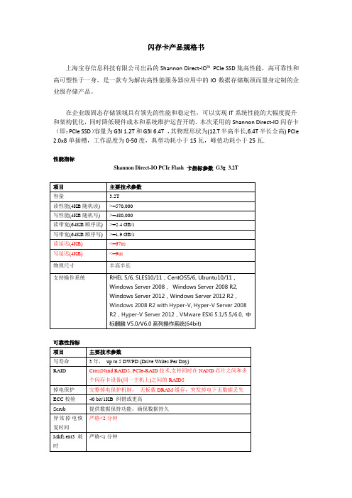
闪存卡产品规格书
上海宝存信息科技有限公司出品的Shannon Direct-IO™PCIe SSD集高性能,高可靠性和高可塑性于一身,是一款专为解决高性能服务器应用中的IO数据存储瓶颈而量身定制的企业级存储产品。
在企业级固态存储领域具有领先的性能和稳定性,可以实现IT系统性能的大幅度提升和架构优化,同时降低硬件成本和系统维护运营开销。
本次采用的Shannon Direct-IO闪存卡(即:PCIe SSD)容量为G3I 1.2T和G3I 6.4T ,其物理形状为(12.T半高半长,6.4T半长全高)PCIe 2.0x8单插槽,工作温度为0-50度,典型功耗小于15瓦,峰值功耗小于25瓦.
性能指标
Shannon Direct-IO PCIe Flash 卡指标参数G3I3.2T
可靠性指标
高级功能
管理性。
hp_2U

HP ProLiant DL380 G7(589152-AA1) 1.84基本参数产品类别 机架式产品结构 2U处理器CPU类型 Intel 至强5600CPU型号 Xeon E5620CPU频率 2.4GHz智能加速主频 2.666GHz标配CPU数量 1颗最大CPU数量 2颗制程工艺 32nm三级缓存 12MB总线规格 QPI 5.86GT/sCPU核心 四核CPU线程数 八线程主板扩展槽 最多6个内存内存类型 DDR3内存容量 6GB内存插槽数量 18最大内存容量 192GB存储硬盘接口类型 SATA/SAS标配硬盘容量 标配不提供最大硬盘容量 8TB热插拔盘位 支持热插拔RAID模式 1个智能阵列 P410i/256MB光驱 标配不提供网络网络控制器 2个NC382i 双端口千兆网卡管理及其他系统管理 iLO 3电源性能电源类型 热插拔电源电源数量 1个电源功率 460WHP ProLiant DL380 G7(583917-B21)1.5基本参数产品类别 机架式产品结构 2U处理器CPU类型 Intel 至强5600CPU型号 Xeon E5620CPU频率 2.4GHz智能加速主频 2.666GHz标配CPU数量 1颗最大CPU数量 2颗制程工艺 32nm三级缓存 12MB总线规格 QPI 5.86GT/sCPU核心 四核CPU线程数 八线程主板扩展槽 最多6个内存内存类型 DDR3内存容量 2GB内存描述 1×2GB PC3-10600E ECC内存内存插槽数量 18最大内存容量 192GB存储硬盘接口类型 SATA/SAS标配硬盘容量 标配不提供内部硬盘架数 最大支持6块LFF热插拔硬盘热插拔盘位 支持热插拔RAID模式 1个集成Smart Array P410i智能阵列控制器,无缓存光驱 薄型SATA DVD-RW网络网络控制器 2个NC382i 双端口千兆网卡管理及其他系统管理 HP Insight Control套件24x7支持iLO 3电源性能电源类型 热插拔高效电源电源数量 1个电源功率 460WHP ProLiant DL380 G7(583914-B21)3.39基本参数产品类别 机架式产品结构 2U处理器CPU类型 Intel 至强5600CPU型号 Xeon E5620CPU频率 2.4GHz智能加速主频 2.666GHz标配CPU数量 2颗最大CPU数量 2颗制程工艺 32nm三级缓存 12MB总线规格 QPI 5.86GT/sCPU核心 四核CPU线程数 八线程主板扩展槽 最多6个内存内存类型 DDR3内存容量 12GB内存描述 6×2GB内存插槽数量 18最大内存容量 192GB存储标配硬盘容量 584GB硬盘描述 4块146GB 2.5英寸硬盘内部硬盘架数 最大支持16块SAS/SATA(SFF)硬盘热插拔盘位 支持热插拔RAID模式 1个集成的智能阵列 P410i,256M缓存光驱 DVD网络网络控制器 2个NC382i 双端口千兆网卡管理及其他系统管理 带iLO高级软件包的 Insight Control (iLO 3)电源性能电源类型 热插拔电源电源数量 2个电源功率 460WHP ProLiant DL380 G7(583966-AA1) 4.05基本参数产品类别 机架式产品结构 2U处理器CPU类型 Intel 至强5600CPU型号 Xeon X5650CPU频率 2.66GHz智能加速主频 3.066GHz标配CPU数量 2颗最大CPU数量 2颗制程工艺 32nm三级缓存 12MB总线规格 QPI 6.4GT/sCPU核心 六核CPU线程数 12线程主板扩展槽 最多6个内存内存类型 DDR3内存容量 12GB内存插槽数量 18最大内存容量 192GB存储硬盘接口类型 SATA/SAS标配硬盘容量 标配不提供最大硬盘容量 8TB热插拔盘位 支持热插拔RAID模式 1个智能阵列 P410i/1GB FBWC光驱 薄型SATA DVD-RW网络网络控制器 2个NC382i 双端口千兆网卡管理及其他系统管理 HP Insight Control套件24x7支持iLO 3电源性能电源类型 热插拔电源电源数量 2个电源功率 750WHP ProLiant DL380 G7(583970-AA1) 4.49基本参数产品类别 机架式产品结构 2U处理器CPU类型 Intel 至强5600CPU型号 Xeon X5660CPU频率 2.8GHz智能加速主频 3.2GHz标配CPU数量 2颗最大CPU数量 2颗制程工艺 32nm三级缓存 12MB总线规格 QPI 6.4GT/sCPU核心 六核CPU线程数 12线程主板扩展槽 最多6个内存内存类型 DDR3内存容量 12GB内存插槽数量 18最大内存容量 192GB存储硬盘接口类型 SATA/SAS标配硬盘容量 标配不提供最大硬盘容量 8TB热插拔盘位 支持热插拔RAID模式 1个智能阵列 P410i/1GB FBWC光驱 薄型SATA DVD-RW网络网络控制器 2个NC382i 双端口千兆网卡管理及其他系统管理 HP Insight Control套件24x7支持iLO 3电源性能电源类型 热插拔电源电源数量 2个电源功率 750WHP ProLiant DL388 G7(QP854A)1.65基本参数产品类别 机架式产品结构 2U处理器CPU类型 Intel 至强5600CPU型号 Xeon E5606CPU频率 2.13GHz标配CPU数量 1颗最大CPU数量 2颗制程工艺 32nm三级缓存 8MB总线规格 QPI 4.8GT/sCPU核心 四核CPU线程数 四线程主板扩展槽 6内存内存类型 DDR3内存容量 2GB内存描述 PC3-10600R RDIMM DDR3 或 PC3-10600E UDIMM DDR3内存插槽数量 18最大内存容量 192GB存储硬盘接口类型 SATA/SAS标配硬盘容量 标配不提供最大硬盘容量 8TB内部硬盘架数 最大支持8块SFF SATA/SAS硬盘热插拔盘位 支持热插拔RAID模式 P410i控制器网络网络控制器 两个NC382i 双端口千兆网卡管理及其他系统管理 iLO 3电源性能电源功率 460W外观特征产品尺寸 85.9×660.7×445.4mm电话备注 周一到周五:8:30-18:00(节假日休息)详细内容 保修于指定日期开始和结束。
9320中文数据手册
20:45
嵌入式系统原理与应用
19
课程回顾
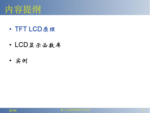
• • • • • void ili9320_Initializtion(void); void ili9320_Clear(u16 dat); void GUI_Color565(u32 RGB); void ili9320_SetPoint(u16 x,u16 y,u16 point); void ili9320_PutChar(u16 x,u16 y,u8 c, u16 charColor, u16 bkColor);
输出参数
返回值
先决条件
无
无
应用示例
20:45
GUI_Line(0,0,319,239,Red)
嵌入式系统原理与应用 21
LCD库函数:GUI_Circle
函数原型 功能描述 输入参数 void GUI_Circle(u16 cx, u16 cy, u16 r, u16 color, u8 fill); 在指定坐标圆 cx:圆心行坐标,cy:圆心列坐标 r:半径,color:线的颜色,fill: 0/1(不填充/填充) 无 无 无 GUI_Circle(160,320,50,Red,1)
功能描述 在指定坐标显示一个16X24点阵的ascii字符 输入参数 x:行坐标,y:列坐标,c:字符, charColor:字符颜色,bkColor:背景颜色 输出参数 无 返回值 无 先决条件 无 应用示例 ili9320_PutChar_16x24(160,120,’A’,Re d,Blue);
合而成的,开发板上ILI9320LCD控制器支持RGB
每种颜色的深度为6位(26万色),为简便处理,在
API程序中我们将颜色深度定义为红(5)、绿(6)、
北京新超仁达数据采集卡产品型录
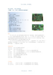
配套端子板 ADAM-3937 P-500 P-800 P-510 P-512 PCLD-789D
DB-37 针孔型接口接线端子 带 1 个 40 针排线接插件和一个 37 针 D-sub 插针通用端子板 带 16 路继电器输出通用端子板 带 8 路隔离数字量输入端子板 带 8 路隔离数字量输出端子板 放大及多路选通板
概述 PCL-812PG 是为 IBM 或其他兼容计算机设计的一款高性能、高速多功能数据采集卡。
PCL-812PG 具备所有数据采集卡的功能,例如,A/D ,D/A 转换,DIO 和定时/计数器,本 卡的高规格使其在需要高速采集的情况下得到广泛应用。PCL-812PG 为低电平输入(例如, 热耦合信号测量)提供专门的高增益可编程仪表放大器。
订货信息 PCL-711B
8 路 12 位 50KS /s 高性价比多功能数据采集
新超控制
3/65
ISA 总线(多功能)
PC-1204 ISA 总线 AD,DA,DIO,脉冲计数/定时中断多功能综合板
特性: AD 输入通道:12 位 100KHz ,*单端 16 路/差分 8 路 AD 输入量程:单极性:0~5V,0~10V* 双极性:±2.5V,±5V,±10V 输入阻抗:>10MΩ;转换误差:<0.20% 输出码制:单极性为二进制原码 双极性为二进制偏移码 工作方式:软件查询、中断 最大差动输入值:20V 输出通道:12 位独立 4 路 输出信号范围: 电压方式:0~5V;0~10V*;±5V;±10V 电流方式:4~20mA 输出阻抗:≤2Ω D/A 转换码制:二进制原码(单极性) 二进制偏移码(双极性) D/A 转换时间:≤1μs D/A 转换综合误差: 电压方式:≤0.2﹪ FSR 电流方式:≤1﹪ FSR 电压输出方式负载能力:5mA/每路 16 路 TTL 电平开关量输入、输出 输出带锁存,输出电流≤2mA
IL300-F中文资料
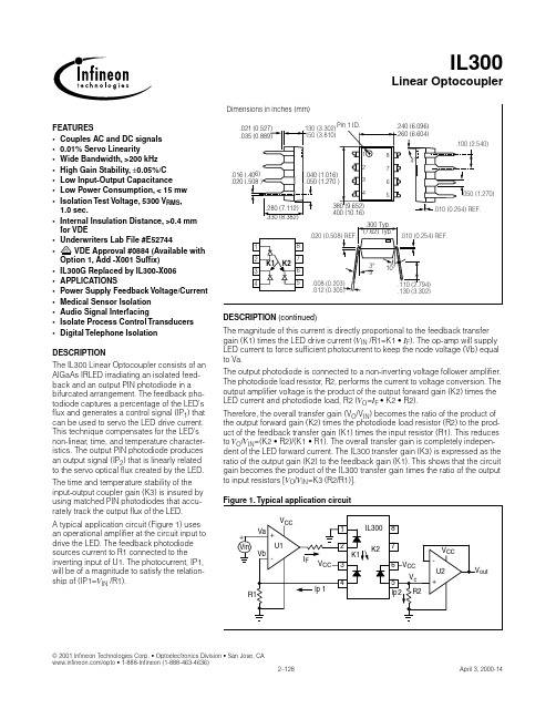
.021 (0.527) .035 (0.889)
.130 (3.302) .150 (3.810)
Pin 1 ID.
.240 (6.096) .260 (6.604) .100 (2.540)
1 2 8 7 6 5
4°
.016 (.406) .020 (.508 )
.040 (1.ቤተ መጻሕፍቲ ባይዱ16) .050 (1.270 )
K1
K2
7 6 5 .008 (0.203) .012 (0.305) 3° 9 10° .110 (2.794) .130 (3.302)
DESCRIPTION (continued) The magnitude of this current is directly proportional to the feedback transfer gain (K1) times the LED drive current (VIN /R1=K1 • IF). The op-amp will supply LED current to force sufficient photocurrent to keep the node voltage (Vb) equal to Va. The output photodiode is connected to a non-inverting voltage follower amplifier. The photodiode load resistor, R2, performs the current to voltage conversion. The output amplifier voltage is the product of the output forward gain (K2) times the LED current and photodiode load, R2 (VO=IF • K2 • R2). Therefore, the overall transfer gain (VO/VIN) becomes the ratio of the product of the output forward gain (K2) times the photodiode load resistor (R2) to the product of the feedback transfer gain (K1) times the input resistor (R1). This reduces to VO/VIN=(K2 • R2)/(K1 • R1). The overall transfer gain is completely independent of the LED forward current. The IL300 transfer gain (K3) is expressed as the ratio of the output gain (K2) to the feedback gain (K1). This shows that the circuit gain becomes the product of the IL300 transfer gain times the ratio of the output to input resistors [VO/VIN=K3 (R2/R1)]. Figure 1. Typical application circuit
ILQ2中文资料

FEATURES•Current Transfer Ratio at I F =10 mA ILD/Q1, 20% Min.ILD/Q2, 100% Min.ILD/Q5, 50% Min.•High Collector-Emitter Voltage ILD/Q1: BV CEO =50 VILD/Q2, ILD/Q5: BV CEO =70 V•Field-Effect Stable by TRansparent IOn Shield (TRIOS) Isolation Test Voltage, 5300 VAC RMS• Underwriters Lab File #E52744• VDE 0884 Available with Option 1Maximum Ratings (Each Channel)EmitterReverse Voltage ................................................6 V Forward Current ...........................................60 mA Surge Current................................................. 2.5 A Power Dissipation.......................................100 mW Derate Linearly from 25 ° C..................... 1.3 mW/ ° C DetectorCollector-Emitter Reverse VoltageILD/Q1........................................................... 50 V ILD/Q2, ILD/Q5...............................................70 V Collector Current.......................................... 50 mA Collector Current (t<1 ms)...........................400 mA Power Dissipation.......................................200 mW Derate Linearly from 25 ° C......................2.6 mW/ ° C PackageIsolation Test Voltage (between emitter and detector referred to standard climate 23 ° C/50%RH,DIN 50014)....................................5300 VAC RMS Creepage...............................................min. 7 mm Clearance...............................................min. 7 mm Isolation ResistanceV IO =500 V , T A =25 ° C .........................R IO =10 12 Ω V IO =500 V , T A =100 ° C .......................R IO =10 11 Ω Package Power Dissipation ...................... 250 mW Derate Linearly from 25 ° C..................... 3.3 mW/ ° C Storage Temperature................... –40 ° C to +150 ° C Operating Temperature................–40 ° C to +100 ° C Junction Temperature....................................100 ° C Soldering Temperature(2 mm from case bottom)..........................260 ° CV D E DESCRIPTIONThe ILD/Q1/2/5 are optically coupled isolated pairs employing GaAs infrared LEDs and silicon NPN phototransistor. Signal information, including a DC level, can be transmitted by the drive while maintaining a high degree of electrical isolation between input and output. The ILD/Q1/2/5 are especially designed for driving medium-speed logic and can be used to eliminate trou-blesome ground loop and noise problems. Also these couplers can be used to replace relays and transformers in many digital interface applica-tions such as CRT modulation. The ILD1/2/5 has two isolated channels in a single DIP package and the ILQ1/2/5 has four isolated channels per pack-age.See Appnote 45, “How to Use Optocoupler Normalized Curves.”Dimensions in inches (mm).268 (6.81).255 (6.48).790 (20.07).779 (19.77 ).045 (1.14).030 (.76).100 (2.54) Typ.3°–9°.305 Typ. (7.75) Typ..022 (.56).018 (.46).012 (.30).008 (.20).135 (3.43).115 (2.92)Pin One I.D.Pin One I.D..150 (3.81).130 (3.30).040 (1.02).030 (.76 ).268 (6.81).255 (6.48)3465.390 (9.91).379 (9.63).045 (1.14).030 (.76)4° Typ.4° Typ..100 (2.54) Typ.10° Typ.10° Typ.3°–9°.305 Typ.(7.75) Typ..022 (.56).018 (.46).012 (.30).008 (.20).135 (3.43).115 (2.92)1287.150 (3.81).130 (3.30).040 (1.02).030 (.76 )12348765Emitter Collector Collector EmitterAnode Cathode Cathode Anode 16151413121110 912345678Emitter Collector Collector Emitter Emitter Collector Collector EmitterAnode Cathode Cathode Anode Anode Cathode Cathode Anode Quad ChannelDual ChannelDUAL CHANNEL ILD1/2/5 QUAD CHANNEL ILQ1/2/5PHOTOTRANSISTOROPTOCOUPLER元器件交易网元器件交易网CharacteristicsSymbol Min.Typ.Max.Unit ConditionEmitterForward Voltage V F 1.25 1.65V I F=60 mAReverse Current I R0.0110µA V R=6 VCapacitance C025pF V R=0 V, f=1 MHzThermal Resistance, Junction to Lead R THJL750°C/WDetectorCapacitance C CE 6.8pF V CE=5 V, f=1 MHzLeakage Current, Collector-Emitter I CEO550nA V CE=10 VSaturation Voltage, Collector-Emitter V CESAT0.250.4I CE=1 mA, I B=20 µADC Forward Current Gain HFE2006501800V CE= 10 V, I B=20 µASaturated DC Forward Current Gain HFE SAT120400600V CE= 0.4 V, I B=20 µAThermal Resistance, Junction to Lead R THJL500°C/WPackage Transfer Characteristics (Each Channel)Symbol Min.Typ.Max.Unit Condition ILD/Q1Saturated Current Transfer Ratio (Collector-Emitter)CTR CESAT75%I F=10 mA, V CE=0.4 VCurrent Transfer Ratio (Collector-Emitter)CTR CE2090300%I F=10 mA, V CE=10 VILD/Q2Saturated Current Transfer Ratio (Collector-Emitter)CTR CESAT170%I F=10 mA, V CE=0.4 VCurrent Transfer Ratio (Collector-Emitter)CTR CE100200500%I F=10 mA, V CE=10 VILD/Q5Saturated Current Transfer Ratio (Collector-Emitter)CTR CESAT100%I F=10 mA, V CE=0.4 VCurrent Transfer Ratio (Collector-Emitter)CTR CE50130400%I F=10 mA, V CE =10 VIsolation and InsulationCommon Mode Rejection, Output High C MH5000V/µs V CM=50 V P-P, R L=1 kΩ, I F=0 mA Common Mode Rejection, Output Low C ML5000V/µs V CM=50 V P-P, R L=1 kΩ, I F=10 mA Common Mode Coupling Capacitance C CM0.01pFPackage Capacitance C IO0.8pF V IO=0 V, f=1 MHzTypical Switching TimesFigure 1. Non-saturated switching timingFigure 2. Non-saturated switching timingFigure 3. Saturated switching timingFigure 4. Saturated switching timingV O V CC =5 VR L =75 ΩF=10 KHz,DF=50%I F =10 mA I FV Ot Dt R50%PHL t PLHt St Ft V OV CC =5 V R L F=10 KHz,DF=50%I F =10 mAI FV Ot Dt RV TH =1.5 Vt PHLt PLHt St FFigure 5. Normalized non-saturated and saturated CTR at T A =25 ° C versus LED currentFigure 6. Normalized non-saturated and saturated CTR at T A =25 ° C versus LED currentCharacteristic ILD/Q1I F =20 mA ILD/Q2I F =5 mA ILD/Q5I F =10 mA Unit ConditionDelay, t D 0.8 1.7 1.7 µ s V CE =5 V R L =75 k Ω 50% of V PPRise time, t R 1.9 2.6 2.6 µ s Storage, t S 0.20.40.4 µ s Fall Time, t F1.42.2 2.2 µ s Propagation H-L, t PHL 0.7 1.2 1.1 µs Propagation L-H, t PLH1.42.32.5µsCharacteristicILD/Q1I F =20 mA ILD/Q2I F =5 mA ILD/Q5I F =10 mA Unit ConditionDelay, t D 0.81 1.7µs V CE =0.4 V R L =1 k ΩV CC =5 V V TH =1.5 VRise time, t R 1.227µs Storage, t S 7.4 5.4 4.6µs Fall Time, t F7.613.520µs Propagation H-L, t PHL 1.6 5.4 2.6µs Propagation L-H, t PLH8.67.47.2µs.11101000.70.80.91.01.11.21.31.4If - Forward Current - mAV f -F o r w a r d V o l t a g e - VTa = -55°CTa = 25°CTa = 100°C.11101000.00.51.01.5NCTR(SAT)NCTRIF - LED Current - mAC T R N F - N o r m a l i z e d C T R F a c t o rNormalized to:Vce = 10V, IF = 10mA Ta = 25°CCTRce(sat) Vce = 0.4V元器件交易网Figure 10. Collector-emitter current versus tempera-ture and LED currentFigure 11. Collector-emitter leakage current versus temperatureFigure 12. Propagation delay versus collector load resistor60504030201000510152025303550°C70°C85°CIF - LED Current - mAI c e - C o l l e c t o r C u r r e n t - m A25°C10080604020-2010-210-1100101102103104105Ta - Ambient Temperature - °CI c e o - C o l l e c t o r -E m i t t e r - n ATYPICALVce = 10V .11101001101001000 1.01.52.02.5RL - Collector Load Resistor - K Ωt P L H - P r o p a g a t i o n L o w -H i g h - µst P H L - P r o p a g a t i o n H i g h -L o w - µstPLHtPHLTa = 25°C, IF = 10mA Vcc = 5V, Vth = 1.5V Figure 7. Normalized non-saturated and saturated CTR at T A =50°C versus LED currentFigure 8. Normalized non-saturated and saturated CTR at T A =70°C versus LED currentFigure 9. Normalized non-saturated and saturated CTR at T A =85°C versus LED current.11101000.00.51.01.5NCTR(SAT)NCTRIF - LED Current - mAC T R N F - N o r m a l i z e d C T R F a c t o rNormalized to:Vce = 10V, IF = 10mA, Ta = 25°C Ta = 50°CCTRce(sat) Vce = 0.4V.11101000.00.51.01.5NCTR(SAT)NCTRIF - LED Current - mAC T R - N o r m a l i z e d C T R F a c t o rNormalized to:Vce = 10V, IF = 10mA Ta = 25°CTa = 70°CCTRce(sat) Vce = 0.4V100101.10.00.51.01.5NCTR(SAT)NCTRNormalized to:Vce = 10V, IF = 10mA, Ta = 25°C Ta = 85°C CTRce(sat) Vce = 0.4VIF - LED Current - mAN C T R - N o r m a l i z e d C T R元器件交易网。
ILGB称重传感器

ILGB称重传感器ILGB称重传感器特性:◆可满足0.05kg-300kg量程范围内的测量。
◆铝合金材料,平行梁结构◆硅橡胶密封,表面阳极化,耐腐蚀性佳。
◆整体结构,安装使用方便。
◆适用于电子计价秤、电子平台秤等各类电子称重设备。
◆量程:0.05㎏到1000㎏◆高精度◆最大秤台尺寸450*450㎜以上内容技术参数以《OIML60号国际建议》92年版为基础,最新具体变化可查看《JJG669—12 Amcells广州南创传感器事业部检定规程》ILGB称重传感器产品图片ILGB称重传感器箱式结构ILC称重传感器:ILC-50kg称重传感器,ILC-75kg称重传感器,ILC-100kg称重传感器,ILC-120kg 称重传感器,ILC-150kg称重传感器,ILC-200kg称重传感器,ILC-250kg称重传感器,ILC-300kg称重传感器,ILC-500kg称重传感器,ILC-750kg。
ILCB称重传感器:ILCB-200kg称重传感器,ILCB-300kg称重传感器,ILCB-500kg称重传感器,ILCB-750kg称重传感器,ILCB-1000kg称重传感器,ILCB-1500kg。
IL称重传感器:IL-50kg称重传感器,IL-100kg称重传感器,IL-150kg称重传感器,IL-200kg称重传感器,IL-250kg称重传感器,IL-300kg称重传感器,IL-500kg称重传感器,IL-750kg称重传感器,IL-1000kg称重传感器,IL-1500kg称重传感器,IL-2000kg。
ILGB称重传感器:ILGB-50kg称重传感器,ILGB-100kg称重传感器,ILGB-200kg称重传感器,ILGB-250kg称重传感器,ILGB-500kg称重传感器,ILGB-750kg称重传感器,ILGB-1000kg称重传感器,ILGB-2000kg。
ILGB-A-50kg称重传感器,ILGB-A-100kg称重传感器,ILGB-A-200kg称重传感器,ILGB-A-250kg称重传感器,ILGB-A-500kg称重传感器,ILGB-A-750kg称重传感器,ILGB-A-1000kg称重传感器,ILGB-A-2000kg。
凌华科技产品介绍

•
特点
• • • • • 低功耗Intel® Core™2 Duo2.2GHz 低功耗 处理器 双通道DDR2-667 SODIMM内存,最 内存, 双通道 内存 高支持4GB 高支持 VGA + DVI独立显示 独立显示 两个PCI-Express千兆以太网端口 两个 千兆以太网端口 支持SATA和CompactFlash存储 和 支持 存储
台湾凌华科技产品介绍
凌华全球经销商布局
高密度同步数据采集
应用: 应用:同步辐射 超声测量 核聚变反应堆 管 道检测等( 道检测等(登陆凌华官方网站 参考技术论坛) 参考技术论坛) 参考技术论坛 解决方案: 用于PXI混合测试系统 解决方案:PXI-3950 用于 混合测试系统 的3U PXI TM intel core 2 Dou PXIS-2719 3U 19槽智能 槽智能PXI机箱, 机箱, 槽智能 机箱 带700W交流电源 交流电源 PXI-2022 16通道 位250KS/S同 通道16位 通道 同 步数据采集卡 PXI-2502 8通道 位1MS/S模拟 通道12位 通道 模拟 输出多功能PXI模块 输出多功能 模块 特性及优点:高采样率和多通道,基于 特性及优点:高采样率和多通道,基于PXI时 时 序和同步机制的多卡同步运行 客户受益:当您的 系统需要多卡同步时, 客户受益:当您的PXI系统需要多卡同步时, 系统需要多卡同步时 采用高密度的PXI-2022不仅可以节省空间, 不仅可以节省空间, 采用高密度的 不仅可以节省空间 更能有效降低您的开发成本
高速数字化仪
应用: 应用:隧道火灾检测 管道泄漏检测 交通 火灾监测 油气设施监测等
解决方案:凌华科技 解决方案:凌华科技PCI-9842是一款单 是一款单 通道14位 高速数字化仪。 通道 位200MS/Sd 高速数字化仪。该 装置输入阻抗50欧姆 输入范围+ 欧姆, 装置输入阻抗 欧姆,输入范围 1V,专 专 为捕获最高达100MHZ的高频信号而设计。 为捕获最高达 的高频信号而设计。 的高频信号而设计 PCIE-9842采用 采用PCI-E*4接口,可实现高 接口, 采用 接口 效的实时数据传输。 效的实时数据传输。 特性及优点: 高速采集率, 高 特性及优点:200M/s高速采集率,14高 高速采集率 精度的分辨率,带自动校准功能, 精度的分辨率,带自动校准功能,高速 接口, 的PCI-E*4接口,最高模拟宽带达 接口 100MHZ 客户受益:低功耗, 客户受益:低功耗,高采集率 ,高温度 分辨率,基于PCI-E接口的快速数据传输 分辨率,基于 接口的快速数据传输
华为存储 RAID2.0+技术介绍

华为存储RAID2.0+技术介绍目录1 RAID技术演变 2 RAID2.0+原理及亮点 3 友商块虚拟化技术介绍RAID技术起源RAID (Redundant Array of Independent Disks)即独立硬盘冗余阵列,1987年由美国加州大学 的伯克利分校提出,其基本思想是把多个独立的物理硬盘通过相关的算法组合成一个虚拟的逻辑硬盘,从而提供更大的容量、更高的性能和更强的数据容错能力。
该技术孕育了外置存储系统市场传统RAID技术的挑战 - 不断扩大的硬盘容量与性能的矛盾硬盘容量走势图(GB)16000 14000 12000 100008000 6000 4000 200002005 2006 2007 2008 2009 2010 2011 2012 2013 2014 2015 2016 20173.5 SATA 2.5" 10K SAS 为了满足数据增长的需求,硬盘设备制造商不断地提升技术来增加 硬盘单位存储密度 2005年硬盘容量仅为250GB,2015年将达到10TB,达到10年前 的40倍。
2005年硬盘的最高访问性能不到100MB/s,2015年能达到 250MB/s左右, 仅为10年前的2.5倍。
传统RAID的重构:应用系统整体性能下降,漫长重构时间、数据 丢失风险剧增。
以 7.2K RPM 4TB硬盘为例,在传统的RAID5 (8D+1P)中,其重构时间在40个小时左右。
可靠性风险很大。
市场需要更加安全可信的RAID技术传统RAID技术的挑战 - 不断扩大的业务需求与规划的矛盾50% 30% 存储市场保持年平均增长10%,意味着存储面临的需求越来越多 计算侧虚拟化整合带来存储侧的整合,单套存储面临的客户更多,更难 规划其容量 传统的、僵硬的、基于硬盘的存储规划无法满足更复杂的业务诉求,带 来更高的CAPEX和OPEX 传统存储规划无法避免热点问题,变相提高了用户成本 软件定义存储的发展趋势要求底层的数据分布架构必须具有高度灵活性 和扩展性市场需要更弹性高效的存储规划方式存储虚拟化技术的发展仅解决规划效率问题, 不能解决重构问题传统RAID 传统RAID厂商热 备LUN虚拟化EMC VMAX、NetApp、 HDS VSP、IBM DS8000块虚拟化华为 OceanStor 18000、 HP 3PAR 10000、 IBM XIV目录1 RAID技术演变 2 RAID2.0+原理及亮点 3 友商块虚拟化技术介绍RAID2.0+概述LUN虚拟化融合卷块级虚拟化融合磁盘RAID2.0+变传统固定管理模式 为两层虚拟化管理模式,在底层块级虚拟化硬盘管理的 基础之上,通过一系列Smart 效率提升软件,实现了LUN虚 拟化的高效资源管理华为RAID2.0+技术关键原理硬盘域硬盘域内每个硬盘被切分为 固定64MB的块(CK) 切分存储池存储池ExtentCKG被划分为固定大小 硬盘域内同种类型的硬盘的被E划x分tent 为一个个的Disk Group(DG), 从同一个DG上随机选择多个硬 盘,每个硬盘选取一个CK按照 RAID算法组成Chunk Group (CKG)LUN T0h(iTckhiLcUk)N以Extent为单 位映射到LUNLUN 1 (Thick)映射ExtentGrainLUN 2 (Thin)Grain在Extent的基础上Thin LUN以Grain 为单 进行更细粒度的划分 位映射到LUN华为RAID2.0+技术关键概念LD(逻辑硬盘)Logical Drive(LD)即逻辑硬盘,是被OceanStor高端存储系统所管理的硬盘,和物理 硬盘一一对应。
AMF25C中文
电路断路器(设定点 MCB 逻辑=“ 断-合 ” )--------------------------------------------------------------------10 双稳定位置 ATS (设定点 MCB 逻辑=“ 通-合” )----------------------------------------------------------------10 三稳定位置 ATS (设定点 MCB 逻辑=“ 断-合 ”)----------------------------------------------------------------11 开始准备----------------------------------------------------------------------------------------------------------12 怎么安装------------------------------------------------------------------------------------------------------12 单相应用------------------------------------------------------------------------------------------------------15 模拟输入------------------------------------------------------------------------------------------------------15 扩展模块(CAN总线)连接-----------------------------------------------------------------------------------20 输入和输出 -------------------------------------------------------------------------------------------------------21 二进制输入IL-CU-默认-------------------------------------------------------------------------------------21 二进制输入-列表----------------------------------------------------------------------------------------------21 二进制输出IL-CU-默认-------------------------------------------------------------------------------------23 二进制输出-列表----------------------------------------------------------------------------------------------23 模拟输入------------------------------------------------------------------------------------------------------29 设定点------------------------------------------------------------------------------------------------------------31 密码----------------------------------------------------------------------------------------------------------31 基本设定------------------------------------------------------------------------------------------------------31 发动机参数----------------------------------------------------------------------------------------------------33 发动机保护----------------------------------------------------------------------------------------------------35 发电机保护------- -------------------------------------------------------------------------------------------37 自动市电故障--------------------------------------------------------------------------------------------------39 传感器特性---------------------------------------------------------------------------------------------------42
ccg3规格书
ccg3规格书CCG3规格书CCG3是一款用于通信设备的规格书,以下将对其进行详细介绍。
一、概述CCG3是一种通信设备,具有高性能和稳定性的特点。
它采用先进的技术,可以在不同的环境下提供可靠的通信服务。
CCG3适用于各种应用场景,如家庭、办公室、商场等。
二、主要特性1. 快速连接:CCG3具有快速连接的特性,可以迅速建立起稳定的通信连接,并提供高速传输速率。
2. 高度可靠:CCG3采用先进的通信技术,具有高度可靠性,可以保证通信的稳定性和安全性。
3. 多种通信方式:CCG3支持多种通信方式,包括有线和无线通信,用户可以根据需要选择适合的通信方式。
4. 多种接口:CCG3提供多种接口,可以连接不同的设备和外部设备,方便用户进行数据传输和共享。
5. 省电模式:CCG3具有省电模式,可以在不使用时自动进入低功耗状态,节省能源。
6. 安全保护:CCG3具有安全保护功能,支持数据加密和身份验证,保护用户的隐私和数据安全。
三、技术规格1. 通信协议:CCG3支持多种通信协议,如TCP/IP、UDP、HTTP等,可以满足不同应用场景的需求。
2. 传输速率:CCG3支持高速传输,最大传输速率可达到100Mbps。
3. 工作频率:CCG3工作频率范围广泛,适用于不同的频率带。
4. 电源要求:CCG3的电源要求为AC 100-240V,50/60Hz。
5. 外部接口:CCG3提供多种外部接口,如以太网接口、USB接口等,方便用户连接和扩展设备。
6. 尺寸和重量:CCG3的尺寸为100mm×100mm×20mm,重量为200g。
四、应用场景1. 家庭网络:CCG3可以作为家庭网络设备,提供稳定的无线网络连接,满足家庭成员对网络的需求。
2. 商业办公:CCG3适用于商业办公场景,可以提供高速、稳定的网络连接,支持多种终端设备同时接入。
3. 公共场所:CCG3可以应用于公共场所,如商场、酒店等,为用户提供便捷的网络访问服务。
KST45-升级型智能脱扣器使用说明书
接地故障整定值
电流整定值 Ir4 时间整定值 t G
(0.2~0.8)In + OFF 可调(级差 ≤ 2A) (最小 100A)
0.10~1.00 + OFF 可调(级差 = 0.1)
谐波影响系数 K
ON + 10%~100% + OFF 可调(级差 = 1%)
负载 1 监控整定值 电流整定值 ILC1
L2 型的瞬时保护整定值按 (3~10)In + OFF ;L3 型和 L4 型的瞬时保护整定值按 (10~20)In + OFF ;当所配套断路器的框架电流 Inm ≥ 3200 A ,瞬时保护整定值按 (7~14)In + OFF 。
某段保护电流整定在“OFF”时,该段保护不工作(或报警)。
表3
状态。 4) 自检功能:环境温度过热自诊断;微控制器自检、A/D 转换自检、E2PROM 自检、磁
通变换器断线自检、空心互感器断线自检。 5) 故障记忆功能:记忆线路故障引起脱扣时的故障类别。 6) 热记忆功能:记忆过载电流引起线路或设备的发热程度。 7) 试验功能:可进行断路器的瞬时脱扣试验。 8) 可增选功能:短路短延时定时限保护、不对称接地(接零)故障保护、报警信号输
在指示灯光柱上显示最大负荷相电流。负荷电流显示范围为(40%~100%)Ir1 + 过载指示; 显示级差为 10% ;显示精度为 3% 。 4.1.7 自诊断功能
当微控制器内部出错或 A/D 转换出错、E2PROM 出错、磁通变换器断线、空心互感器断线 时智能脱扣器能用“MCU”灯的闪烁次数表示相应的自诊断错误信息,如表 7 所示(用户需要时 也可将断路器分断);如果同时出现多个自诊断故障,则按表 7 中的次序自上而下优先显示在上
不同组织学类型乳腺癌的临床病理特征分析

2结 果 2.1 三组患者一般资料结果 共纳入709例乳腺癌患者,其中 IDC-L组为9例,ILC组为22例,IDC组为678例;三组患者年 龄是IDC-L、ILC、IDC的临床病理特征(P<0.05),而绝经情 况、孕次、产次比较均无统计学意义(P均>0.05),见表1。
项目 年龄(岁) 绝经情况 孕次(次) 产次(次)
表2 三组患者临床病理特征结果比较[n(%)]
ILC(n=22)
IDC(n=678)
IDC-L(n=9)
18(81.8)
472(69.6)
5(55.6)
4(18.2)
206(30.4)
4(44.4)
17(77.3)
529(78.0)
2(22.2)
5(22.7)
149(22.0)
7(77.8)
1.2 方法 1.2.1 临床病理特征 依据雌激素受体(ER)、PR、HER-2与 Ki67表达水平差异,将乳腺癌患者划分为Luminal A型、 Luminal B型、HER2阳性型与三阴型。 1.2.2 蛋白表达检测 (1)组织标本处理与检测:术中切除后 的病理组织,放置于10%中性缓冲福尔马林液中保存,依据 组织大小固定6~48h,石蜡包埋后标本制成4~5μm厚度的切 片,加以保存备用。(2)免疫组织化学法检测:常规使用二甲 苯对组织切片进行脱蜡,并采用梯度酒精进行脱水,在微波 炉内放入柠檬酸溶液缓冲液进行抗原修复。根据SP染色法, 将切片孵育鼠抗原HER-2一抗放置在4℃冰箱内保存,在生物 素标记二抗室温孵育30min,使用磷酸缓冲盐溶液冲洗,滴 入辣根酶标记链霉卵白素孵育30min,应用DAB-H2O2显色 剂进行显色,再使用苏木精复染,使用中性树胶封片观察。 (3)结果判定:依据阳性细胞比例与着色程度进行对比,分为 4级,无染色或<10%肿瘤细胞有细胞膜着色表示0级;染色
IL300-DEFG-X007资料
IL300Document Number 83622Vishay SemiconductorsLinear Optocoupler, High Gain Stability, Wide BandwidthFeatures•Couples AC and DC signals •0.01 % Servo Linearity•Wide Bandwidth, > 200 kHz•High Gain Stability, ± 0.05 %/°C •Low Input-Output Capacitance•Low Power Consumption, < 15 mW•Isolation Test Voltage, 5300 V RMS , 1.0 sec. •Internal Insulation Distance, > 0.4 mm for VDE •Component in accordance to RoHS 2002/95/EC and WEEE 2002/96/ECAgency Approvals•UL File #E52744•DIN EN 60747-5-2 (VDE0884)DIN EN 60747-5-5 pendingAvailable with Option 1, Add -X001 SuffixApplicationsPower Supply Feedback Voltage/Current Medical Sensor Isolation Audio Signal InterfacingIsolated Process Control Transducers Digital Telephone IsolationDescriptionThe IL300 Linear Optocoupler consists of an AlGaAs IRLED irradiating an isolated feedback and an output PIN photodiode in a bifurcated arrangement. The feedback photodiode captures a percentage of the LE D’s flux and generates a control signal (I P1) that can be used to servo the LED drive current. This tech-nique compensates for the LE D’s non-linear, time,and temperature characteristics. The output PIN pho-todiode produces an output signal (I P2) that is linearly related to the servo optical flux created by the LED.The time and temperature stability of the input-output coupler gain (K3) is insured by using matched PIN photodiodes that accurately track the output flux of the LED.Order InformationFor additional information on the available options refer to Option Information.PartRemarksIL300K3 = 0.557 - 1.618, DIP-8IL300-DEFG K3 = 0.765 - 1.181, DIP-8IL300-EF K3 = 0.851 - 1.061, DIP-8IL300-E K3 = 0.851 - 0.955, DIP-8IL300-F K3 = 0.945 - 1.061, DIP-8IL300-X006K3 = 0.557 - 1.618, DIP-8 400mil (option 6)IL300-X007K3 = 0.557 - 1.618, SMD-8 (option 7)IL300-X009K3 = 0.557 - 1.618, SMD-8 (option 9)IL300-DEFG-X006K3 = 0.765 - 1.181, DIP-8 400 mil (option 6)IL300-DEFG-X007K3 = 0.765 - 1.181, SMD-8 (option 7)IL300-DEFG-X009K3 = 0.765 - 1.181, SMD-8 (option 9)IL300-EF-X006K3 = 0.851 - 1.061, DIP-8 400 mil (option 6)IL300-EF-X007K3 = 0.851 - 1.061, SMD-8 (option 7)IL300-EF-X009K3 = 0.851 - 1.061, SMD-8 (option 9)IL300-E-X006K3 = 0.851 - 0.955, DIP-8 400 mil (option 6)IL300-E-X007K3 = 0.851 - 0.955, SMD-8 (option 7)IL300-E-X009K3 = 0.851 - 0.955, SMD-8 (option 9)IL300-F-X006K3 = 0.945 - 1.061, DIP-8 400 mil (option 6)IL300-F-X007K3 = 0.945 - 1.061, SMD-8 (option 7)IL300-F-X009K3 = 0.945 - 1.061, SMD-8 (option 9) Document Number 83622IL300Vishay Semiconductors Operation DescriptionA typical application circuit (Figure 1) uses an opera-tional amplifier at the circuit input to drive the LE D.The feedback photodiode sources current to R1 con-nected to the inverting input of U1. The photocurrent,I P1, will be of a magnitude to satisfy the relationship of (I P1 = V IN /R1).The magnitude of this current is directly proportional to the feedback transfer gain (K1) times the LED drive current ( V IN /R1 = K1 • I F ). The op-amp will supply LED current to force sufficient photocurrent to keep the node voltage (Vb) equal to Va.The output photodiode is connected to a non-invert-ing voltage follower amplifier. The photodiode load resistor, R2, performs the current to voltage conver-sion. The output amplifier voltage is the product of the output forward gain (K2) times the LED current and photodiode load, R2 ( V O = I F • K2 • R2).Therefore, the overall transfer gain (V O /V IN ) becomes the ratio of the product of the output forward gain (K2)times the photodiode load resistor (R2) to the product of the feedback transfer gain (K1) times the input resistor (R1). This reduces to V O /V IN =(K2 • R2)/(K1 • R1).The overall transfer gain is completely independent of the LED forward current. The IL300 transfer gain (K3)is expressed as the ratio of the output gain (K2) to the feedback gain (K1). This shows that the circuit gain becomes the product of the IL300 transfer gain times the ratio of the output to input resistors V O /V IN = K3 (R2/R1).K1-Servo GainThe ratio of the input photodiode current (I P1) to the LED current (I F ) i.e., K1 = I P1/I F .K2-Forward GainThe ratio of the output photodiode current (I P2) to the LED current (I F ), i.e., K2 = I P2/I F .K3-Transfer GainThe Transfer Gain is the ratio of the Forward Gain to the Servo gain, i.e., K3 = K2/K1.∆K3-Transfer Gain LinearityThe percent deviation of the Transfer Gain, as a func-tion of LE D or temperature from a specific Transfer Gain at a fixedLED current and temperature.PhotodiodeA silicon diode operating as a current source. The out-put current is proportional to the incident optical flux supplied by the LED emitter. The diode is operated in the photovoltaic or photoconductive mode. In the pho-tovoltaic mode the diode functions as a current source in parallel with a forward biased silicon diode.The magnitude of the output current and voltage is dependent upon the load resistor and the incident LED optical flux. When operated in the photoconduc-tive mode the diode is connected to a bias supply which reverse biases the silicon diode. The magni-tude of the output current is directly proportional to the LED incident optical flux.LED (Light Emitting Diode)An infrared emitter constructed of AlGaAs that emits at 890 nm operates efficiently with drive current from 500 µA to 40 mA. Best linearity can be obtained at drive currents between 5.0 mA to 20 mA. Its output flux typically changes by - 0.5 % /°C over the above operational current range.Application CircuitFigure 1. Typical Application CircuitoutIL300Document Number 83622Vishay SemiconductorsAbsolute Maximum RatingsT amb = 25°C, unless otherwise specifiedStresses in excess of the absolute Maximum Ratings can cause permanent damage to the device. Functional operation of the device is not implied at these or any other conditions in excess of those given in the operational sections of this document. Exposure to absolute Maximum Rating for extended periods of the time can adversely affect reliability.InputOutputCouplerParameterT est conditionSymbol Value Unit Power dissipation P diss160mW Derate linearly from 25°C 2.13mW/°C Forward currentI F 60mA Surge current (pulse width < 10 µs)I PK 250mA Reverse voltage V R 5.0V Thermal resistance R th 470K/W Junction temperatureT j100°CParameterT est conditionSymbol Value Unit Power dissipation P diss50mA Derate linearly from 25°C 0.65mW/°C Reverse voltage V R 50V Junction temperature T j 100°C Thermal resistanceR th1500K/WParameterTest conditionSymbol Value Unit Total package dissipation at 25°CP tot210mW Derate linearly from 25°C 2.8mW/°C Storage temperature T stg - 55 to + 150°C Operating temperature T amb- 55 to + 100°C Isolation test voltage > 5300V RMS Isolation resistanceV IO = 500 V , T amb = 25°C R IO > 1012ΩV IO = 500 V , T amb = 100°CR IO > 1011Ω Document Number 83622IL300Vishay Semiconductors Electrical CharacteristicsT amb = 25°C, unless otherwise specifiedMinimum and maximum values are testing requirements. Typical values are characteristics of the device and are the result of engineering evaluation. Typical values are for information only and are not part of the testing requirements.InputLED EmitterOutputParameterTest conditionSymbol MinT yp.Max Unit Forward voltageI F = 10 mAV F 1.25 1.50V V F T emperature coefficient ∆V F /∆°C- 2.2mV/°C Reverse current V R = 5 VI R 1.0µA Junction capacitance V F = 0 V , f = 1.0 MHz C j 15pF Dynamic resistanceI F = 10 mA∆V F /∆I F6.0ΩParameterTest conditionSymbol MinT yp.Max Unit Dark current V det = -15 V , I F = 0 µs I D 1.025nA Open circuit voltage I F = 10 mA V D 500mV Short circuit current I F = 10 mA I SC 70µA Junction capacitance V F = 0, f = 1.0 MHz C j 12pF Noise equivalent powerV det = 15 VNEP4 x 1014W/√HzIL300Document Number 83622Vishay SemiconductorsCoupler1. Bin Sorting:K3 (transfer gain) is sorted into bins that are ± 6 % , as follows:Bin A = 0.557 - 0.626Bin B = 0.620 - 0.696Bin C = 0.690 - 0.773Bin D = 0.765 - 0.859Bin E = 0.851 - 0.955Bin F = 0.945 - 1.061Bin G = 1.051 - 1.181Bin H = 1.169 - 1.311Bin I = 1.297 - 1.456Bin J = 1.442 - 1.618K3 = K2/K1. K3 is tested at I F = 10 mA, V det = - 15 V.2. Bin Categories: All IL300s are sorted into a K3 bin, indicated by an alpha character that is marked on the part. The bins range from "A"through "J".The IL300 is shipped in tubes of 50 each. Each tube contains only one category of K3. The category of the parts in the tube is marked on the tube label as well as on each individual part.3. Category Options: Standard IL300 orders will be shipped from the categories that are available at the time of the order. Any of the ten categories may be shipped. For customers requiring a narrower selection of bins, four different bin option parts are offered.IL300-DEFG: Order this part number to receive categories D,E,F,G only.IL300-EF: Order this part number to receive categories E, F only.IL300-E: Order this part number to receive category E only.Switching CharacteristicsParameterTest conditionSymbolMinTyp.MaxUnit Input- output capacitance V F = 0 V , f = 1.0 MHz 1.0pFK1, Servo gain (I P1/I F )I F = 10 mA, V det = - 15 V K10.00500.0070.011Servo current, see Note 1,2I F = 10 mA, V det = - 15 V I P170µAK2, Forward gain (I P2/I F )I F = 10 mA, V det = - 15 V K20.00360.0070.011Forward currentI F = 10 mA, V det = - 15 V I P270µA K3, Transfer gain (K2/K1) see Note 1,2I F = 10 mA, V det = - 15 V K30.56 1.00 1.65K2/K1Transfer gain linearityI F = 1.0 to 10 mA ∆K3± 0.25%I F = 1.0 to 10 mA, T amb = 0°C to 75°C± 0.5%Photoconductive Operation Frequency response I Fq = 10 mA, MOD = ± 4.0 mA, R L = 50 ΩBW (-3 db)200KHz Phase response at 200 kHz V det = - 15 V-45Deg.ParameterTest conditionSymbol MinTyp.MaxUnit Switching time ∆I F = 2.0 mA, I Fq = 10 mAt r 1.0µs t f 1.0µs Rise time t r 1.75µs Fall timet f1.75µs Document Number 83622IL300Vishay SemiconductorsCommon Mode Transient ImmunityTypical Characteristics (Tamb = 25 °C unless otherwise specified)ParameterTest conditionSymbol MinT yp.MaxUnit Common mode capacitance V F = 0, f = 1. MHz C CM 0.5pF Common mode rejection ratiof = 60 Hz, R L = 2.2 K ΩCMRR130dBFigure 2. LED Forward Current vs.Forward Voltage Figure 3. LED Forward Current vs.Forward Voltage iil300_02I F -L E D C u r r e n t -m Aiil300_031.01.1 1.2 1.3 1.4.1110VF -LED Forward Voltage -VI F -L E D C u r r e n t -m AFigure 4. Servo Photocurrent vs. LED Current and TemperatureFigure 5. Servo Photocurrent vs. LED Current and Temperatureiil300_04.1110100300250200150100500I F -LED Current -mAI P 1-S e r v o P h o t o c u r r e n t -µAiil300_05.11101001000100101I F -LED Current -mAI P 1-S e r v o P h o t o c u r r e n t -µAIL300Document Number 83622Vishay SemiconductorsFigure 6. Normalized Servo Photocurrent vs. LED Current andTemperature Figure 7. Normalized Servo Photocurrent vs. LED Current andTemperatureFigure 8. Servo Gain vs. LED Current and Temperatureiil300_065101520253.02.52.01.51.00.50.0I F -LED Current -mAN o r m a l i z e d P h o t o c u r r e n tiil300_07.1110100101.1.01I F -LED Current -mAI P 1-N o r m a l i z e d P h o t o c u r r e n tiil300_08.1110100I F -LED Current -mAN K 1-N o r m a l i z e d S e r v o G a i n1.21.00.80.60.40.20.0Figure 9. Normalized Servo Gain vs. LED Current andTemperatureFigure 10. Transfer Gain vs. LED Current and TemperatureFigure 11. Normalized Transfer Gain vs. LED Current andTemperatureiil300_09.1110100I F -LED Current -mAN K 1-N o r m a l i z e d S e r v o G a i n1.21.00.80.60.40.20.0iil300_1005101520251.0101.0051.0000.9950.990I F -LED Current -mAK 3-T r a n s f e r G a i n -(K 2/K 1)0°C25°C50°C 75°Ciil300_115101520251.0101.0051.0000.9950.990I F -LED Current -mAK 3-T r a n s f e r G a i n -(K 2/K 1) Document Number 83622IL300Vishay SemiconductorsApplication ConsiderationsIn applications such as monitoring the output voltage from a line powered switch mode power supply, mea-suring bioelectric signals, interfacing to industrial transducers, or making floating current measure-ments, a galvanically isolated, DC coupled interface is often essential. The IL300 can be used to construct an amplifier that will meet these needs.The IL300 eliminates the problems of gain nonlinear-ity and drift induced by time and temperature, by mon-itoring LED output flux.A PIN photodiode on the input side is optically cou-pled to the LED and produces a current directly pro-portional to flux falling on it. This photocurrent, when coupled to an amplifier, provides the servo signal that controls the LED drive current.The LED flux is also coupled to an output PIN photo-diode. The output photodiode current can be directly or amplified to satisfy the needs of succeeding cir-cuits.Isolated Feedback AmplifierThe IL300 was designed to be the central element of DC coupled isolation amplifiers. Designing the IL300into an amplifier that provides a feedback control sig-nal for a line powered switch mode power is quite sim-ple, as the following example will illustrate.See Figure 17 for the basic structure of the switch mode supply using the Infineon TDA4918 Push-Pull Switched Power Supply Control Chip. Line isolation and insulation is provided by the high frequency transformer. The voltage monitor isolation will be pro-vided by the IL300.Figure 12. Amplitude Response vs. Frequency Figure 13. Amplitude and Phase Response vs. FrequencyFigure 14. Common-Mode Rejectioniil300_1210101050-5-10-15-20F -Frequency -HzA m p l i t u d e R e s p o n s e -d Biil300_13∅-P h a s e R e s p o n s e -°10310410510610750-5-10-15-20450-45-90-135-180F -Frequency -HzA m p l i t u d e R e s p o n se -d Biil300_14101001000100001000001000000-130-120-110-100F -Frequency -HzC M R R -R e j e c t i o n R a t i o -d BFigure 15. Photodiode Junction Capacitance vs. Reverse Voltageiil300_15Voltage -V detC a p a c i t a n c e -p F246810IL300Vishay Semiconductors Document Number 83622IL300Vishay SemiconductorsTable 1. gives the value of R5 given the production K3bins.R5 SelectionTable 1.Figure 17. Switching Mode Power SupplyFigure 18. DC Coupled Power Supply Feedback Amplifieriil300_17iil300_18V To control inputBins Min.Max.3Typ.R5 ResistorK Ω1% K ΩA 0.5600.6230.5950.8551.1B 0.6230.6930.6645.4545.3C 0.6930.7690.7341.141.2D 0.7690.8550.8137.0437.4E 0.8550.9500.9332.2632.4F 0.950 1.056 1.0030.0030.0G 1.056 1.175 1.1127.0327.0H 1.175 1.304 1.2424.1924.0I 1.304 1.449 1.3721.9022.0J1.4491.6101.5319.6119.4IL300Vishay Semiconductors The last step in the design is selecting the LED cur-rent limiting resistor (R4). The output of the opera-tional amplifier is targeted to be 50 % of the V CC, or2.5 V. With an LED quiescent current of 12 mA thetypical LED (V F) is 1.3 V. Given this and the opera-tional output voltage, R4 can be calculated.The circuit was constructed with an LM201 differentialoperational amplifier using the resistors selected. Theamplifier was compensated with a 100 pF capacitorconnected between pins 1 and 8.The DC transfer characteristics are shown in Figure19. The amplifier was designed to have a gain of 0.6and was measured to be 0.6036. Greater accuracycan be achieved by adding a balancing circuit, andpotentiometer in the input divider, or at R5. The circuitshows exceptionally good gain linearity with an RMSerror of only 0.0133 % over the input voltage range of4.0 V - 6.0 V in a servo mode; see Figure 20.The AC characteristics are also quite impressiveoffering a - 3.0 dB bandwidth of 100 kHz, with a -45°phase shift at 80 kHz as shown in Figure 21.The same procedure can be used to design isolationamplifiers that accept bipolar signals referenced toground. These amplifiers circuit configurations are Figure19. Transfer Gainiil300_19Vout-OutputVoltage-VFigure20. Linearity Error vs. Input VoltageFigure21. Amplitude and Phase Power Supply Controliil300_21PhaseResponse-°1031041051062-2-4-6-845-45-90-135-180F-Frequency-HzAmplitudeResponse-dB 12Document Number 83622 Rev. 1.5, 24-Mar-05IL300Vishay Semiconductors Table 2. Optolinear amplifiersinverting transfer gain based upon the type of input and output amplifier. Table 2 shows the various con-figurations along with the specific transfer gain equa-tions. The offset column refers to the calculation of the output offset or V ref2 necessary to provide a zero volt-input amplifier requires the use of a bipolar supply, while the inverting input stage can be implemented with single supply operational amplifiers that permit operation close to ground.Figure22. Non-inverting and Inverting AmplifiersIL300Document Number 83622Rev. 1.5, 24-Mar-05Vishay Semiconductors13For best results, place a buffer transistor between the LED and output of the operational amplifier when a CMOS opamp is used or the LED I Fq drive is targeted to operate beyond 15 mA. Finally the bandwidth isinfluenced by the magnitude of the closed loop gain of the input and output amplifiers. Best bandwidths result when the amplifier gain is designed for unity.Package Dimensions in Inches (mm) 14Document Number 83622 Rev. 1.5, 24-Mar-05IL300Vishay SemiconductorsOzone Depleting Substances Policy StatementIt is the policy of Vishay Semiconductor GmbH to1.Meet all present and future national and international statutory requirements.2.Regularly and continuously improve the performance of our products, processes, distribution and operatingsystems with respect to their impact on the health and safety of our employees and the public, as well as their impact on the environment.It is particular concern to control or eliminate releases of those substances into the atmosphere which are known as ozone depleting substances (ODSs).The Montreal Protocol (1987) and its London Amendments (1990) intend to severely restrict the use of ODSs and forbid their use within the next ten years. Various national and international initiatives are pressing for an earlier ban on these substances.Vishay Semiconductor GmbH has been able to use its policy of continuous improvements to eliminate the use of ODSs listed in the following documents.1.Annex A, B and list of transitional substances of the Montreal Protocol and the London Amendmentsrespectively2.Class I and II ozone depleting substances in the Clean Air Act Amendments of 1990 by the EnvironmentalProtection Agency (EPA) in the USA3.Council Decision 88/540/EEC and 91/690/EEC Annex A, B and C (transitional substances) respectively. Vishay Semiconductor GmbH can certify that our semiconductors are not manufactured with ozone depleting substances and do not contain such substances.We reserve the right to make changes to improve technical designand may do so without further notice.Parameters can vary in different applications. All operating parameters must be validated for each customer application by the customer. Should the buyer use Vishay Semiconductors products for any unintended or unauthorized application, the buyer shall indemnify Vishay Semiconductors against all claims, costs, damages, and expenses, arising out of, directly or indirectly, any claim of personal damage, injury or death associated with such unintended or unauthorized use.Vishay Semiconductor GmbH, P.O.B. 3535, D-74025 Heilbronn, GermanyDocument Number: 91000Revision: 18-Jul-081DisclaimerLegal Disclaimer NoticeVishayAll product specifications and data are subject to change without notice.Vishay Intertechnology, Inc., its affiliates, agents, and employees, and all persons acting on its or their behalf (collectively, “Vishay”), disclaim any and all liability for any errors, inaccuracies or incompleteness contained herein or in any other disclosure relating to any product.Vishay disclaims any and all liability arising out of the use or application of any product described herein or of any information provided herein to the maximum extent permitted by law. The product specifications do not expand or otherwise modify Vishay’s terms and conditions of purchase, including but not limited to the warranty expressed therein, which apply to these products.No license, express or implied, by estoppel or otherwise, to any intellectual property rights is granted by this document or by any conduct of Vishay.The products shown herein are not designed for use in medical, life-saving, or life-sustaining applications unless otherwise expressly indicated. Customers using or selling Vishay products not expressly indicated for use in such applications do so entirely at their own risk and agree to fully indemnify Vishay for any damages arising or resulting from such use or sale. Please contact authorized Vishay personnel to obtain written terms and conditions regarding products designed for such applications.Product names and markings noted herein may be trademarks of their respective owners.元器件交易网。
乳腺疾病超声诊断及BI-RADS分级

乳腺增生症
5
精选ppt
病理、临床表现 乳腺增生症是非炎症非肿瘤 的乳腺良性疾病,名称很多,如囊性增生症、 囊性乳腺病、乳腺小叶增生病、乳腺腺病等。 多见于30-40岁妇女,由于卵巢功能发生紊乱, 黄体素分泌减少,雌激素相对增多,而引起的 乳腺的导管及小叶上皮随月经周期而发生增生 及复原。临床表现为月经来潮前3-4天,乳房 一侧或两侧出现间歇性胀痛,扪及多个大小不 等的结节,有压痛,月经过后,症状缓解。
乳腺癌超声表现
37
精选ppt
超声表现 声像图表现一般呈不均质的低回声团块,形态不规则, 无包膜,周围凹凸不平,有角状突起或蟹足样延伸,有的肿块周边显 示强回声带,有的肿块内部显示较强的粗斑点状回声。CDFI示肿块内 部及周边点条状彩色血流信号。根据病理不同,肿瘤的声像图存在一 定差异。如硬癌其体积小,大多为纤维组织故质地坚硬,声像图显示 肿瘤边界不整齐,境界不清,后方回声明显衰减。髓样癌表现为瘤体 较大,边界光滑,内部为等回声,部分为无回声区,后方回声不衰减, 有时反而增强。特别注意炎性乳腺癌,其声像图表现为皮肤及皮下组 织增厚,回声增强,腺体结构紊乱,常不能发现肿块。
乳腺癌是女性最常见的恶性肿瘤之一,其发病率呈明显 上升趋势
发病年龄多在40~60岁,其病因仍不太清楚
乳腺癌的治疗方法和预后主要取决于肿瘤的早期发现、 早期诊断
乳腺肿瘤血管在诊断、判断预后、了解术前化疗效果等 方面有重要的作用
乳腺癌
24
精选ppt
病理、临床表现 乳腺癌是乳腺导管上皮及末梢导管上皮 发生的恶性肿瘤。据国内统计,除子宫癌外,乳腺癌占女 性恶性肿瘤的第二位。大多发生40~60岁、绝经期前后的 妇女。早期表现为无痛、单发的小肿块,质硬,表面不光 滑,与周围组织分界不清,在乳房内不易被推动。乳腺癌 逐渐增大,侵入Cooper韧带,肿块处皮肤往往有凹陷。随 着肿瘤逐渐增大,可出现乳房缩小,变硬,腋下淋巴结肿 大,连结成硬结,晚期,肿瘤侵入胸大肌,与之固定,并 与皮下组织广泛粘连,形成“桔皮样”外形,并且发生溃 破。
- 1、下载文档前请自行甄别文档内容的完整性,平台不提供额外的编辑、内容补充、找答案等附加服务。
- 2、"仅部分预览"的文档,不可在线预览部分如存在完整性等问题,可反馈申请退款(可完整预览的文档不适用该条件!)。
- 3、如文档侵犯您的权益,请联系客服反馈,我们会尽快为您处理(人工客服工作时间:9:00-18:30)。
元器件交易网
PACKAGE OUTLINE
ILC-3F-2.0G
THE MULTI-MIX MICROTECHNOLOGY® GROUP IS ISO-9001 REGISTERED
Merrimac Industries, Inc. / 41 Fairfield Place, West Caldwell, NJ 07006 Tel: 1.888.434.MMFM / Fax: 973.882.5990 / Email: MMFM@ /
Isolation
0
-5
-10
Magnitude (dB)
-15
-20
2-4 2-3 3-4
-25
-30
-35 1800
1850
1900
1950 Frequency (MHz)
2000
2050
2100
THE MULTI-MIX MICROTECHNOLOGY® GROUP IS ISO-9001 REGISTERED
MUTLI-MIX® F SERIES IN-LINE COUPLERS
The Multi-Mix® ILC-F series provides a power divider and combiner function with low insertion loss, high isolation, and high power handling in a small outline. The ILC series are composed of serial connected multi-couplers with each coupler having a different nominal coupling value. Equal split loss is maintained at all of the coupled ports, since the direct-path loss of previous couplers is added. Each of the paths through a divider / combiner pair have equal insertion phase, but the individual port paths do not. Accurate phase and amplitude balance make them ideal for applications involving power amplifiers, signal distribution and processing. ILC-F in-line couplers are fusion bonded multilayer stripline assemblies. The fusion bonding process yields a homogeneous monolithic dielectric structure with reliability, ruggedness, and electrical performance that is superior to conventional adhesive bonding techniques. The ILC-F series is an easy to install SMD designed specifically for the full spectrum of wireless applications. The high stability ceramic filled PTFE dielectrics utilized in these components are compatible with common substrates such as FR-4, G-10, and polyamide. The wrap around ground plane provides excellent EM shielding. Additional benefits include: • • • Cost effective for commercial wireless applications Operating temperature range –55°C to +85°C. Can be integrated with other Multi-Mix® components in a multi-function module
元器件交易网
TYPICAL PERFORMANCE
ILC-3F-2.0G
Return Loss
0ቤተ መጻሕፍቲ ባይዱ
-5
-10
Magnitude (dB)
-15 Port 1 -20 Port 2 Port 3 Port 4 -25
-30
-35
-40 1800
1850
1900
1950 Frequency (MHz)
2000
2050
2100
Coupling
-4.5 -4.6 -4.7 -4.8 -4.9 -5 -5.1 -5.2 -5.3 -5.4 -5.5 1800 1850 1900 1950 Frequency (MHz) 2000 2050 2100 Coupling 1-2 Coupling 1-3 Coupling 1-4
RELIABILITY The product family has passed environmental screening including Thermal shock, Burn-in, Acceleration, Vibration, Mechanical Shock, Moisture Resistance, Resistance to Solder Heat, and Thermal Cycling Life Test (>1000 cycles). THE MULTI-MIX® PROCESS Multi-Mix® is a manufacturing process based on fluoropolymer composite substrates that are fusion bonded together into a multilayer structure. The fusion bonding process yields a homogeneous monolithic structure with superior performance at microwave and millimeter wave frequencies. The bonded layers can contain embedded semiconductors, MMICs, etched resistors, circuit patterns, and plated-through vias to form a SMD module that requires no additional packaging and is suitable for automated assembly. THE MULTI-MIX MICROTECHNOLOGY® GROUP IS ISO-9001 REGISTERED
NOTES: 1. ALL DIMENSIONS ARE IN INCHES. 2. TOLERANCES: -3 PLACE DECIMALS; ±.005.
MEC H AN IC AL SIZE / OUTLINE WEIGHT RF INTERFAC E 4.28 x 0.4 x 0.07 i nches 0.19 oz. (5.2 g) Surface Mount
EN VIR ON MEN TAL OPERATING TEMPERATURE RANGE -55° To + 85°, C
Merrimac Industries, Inc. / 41 Fairfield Place, West Caldwell, NJ 07006 Tel: 1.888.434.MMFM / Fax: 973.882.5990 / Email: MMFM@ /
Magnitude (dB)
THE MULTI-MIX MICROTECHNOLOGY® GROUP IS ISO-9001 REGISTERED
Merrimac Industries, Inc. / 41 Fairfield Place, West Caldwell, NJ 07006 Tel: 1.888.434.MMFM / Fax: 973.882.5990 / Email: MMFM@ /
元器件交易网
ILC-3F-2.0G
IN-LINE COUPLERS
REV: 002, 09/18/01
• 1.8 - 2.1 GHz • LOW LOSS • LOW VSWR • HIGH ISOLATION • SURFACE MOUNT
TECHNICAL DESCRIPTION / APPLICATION
元器件交易网
TYPICAL PERFORMANCE
ILC-3F-2.0G
Insertion Loss
0
-0.1
Magnitude (dB)
-0.2 Insertion Loss -0.3
-0.4
-0.5 1800 1850 1900 1950 Frequency (MHz) 2000 2050 2100
元器件交易网
GENERAL SPECIFICATIONS
ILC-3F-2.0G
ELEC TR IC AL FREQUENC Y NOMINAL C OUPLING INSERTION LOSS VSWR AMPLITUD E BALANC E ISOLATION MAXIMUM INPUT POWER 1.8 TO 2.1 GHz 4.8 dB 0.25 dB (TYP), 0.35 dB (MAX) 1.25:1 (MAX) ±0.2 dB (TYP), ±0.4 dB (MAX) 22 dB (MIN) 100 W (MAX)
