Sol–gel-deposited ZnO thin films A review
sol-gel法制备的ZnO:(Al,La)透明导电膜光电性能
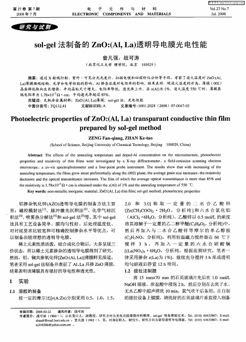
关键 词:无机 非金属材料 ;Z O: , a薄膜:sl e 法;光 电性 能 n ( L) AI o— 1 g
中 图分 类 号 : Q1 2 1 T 3. 4 文献标识码 : A 文 章 编 号 :0 12 2 (0 8 70 4 —3 10 —0 8 2 0 )0 —0 70
te ei ii i 1 8 1 一 Q ・ m i o tie n e te A1 o 1 a dte n e l gtm eaue f 5 ℃. h s t t s . x 0 r sv v 7 c s ba d d r h ( ) f % n h n a n e p rtr 5 0 n u a i o K ywo d : o ・ t l og ncm t i ; n ( , a ti f m; o—e meh d p oo lc i p o e is e r s n n me l c n ra i ae a Z O: L ) hn i s l l to ; h tee t c rp r e aii rl Al l g r t
维普资讯
第2 7卷 第 7期 2 0 年 7月 08
电
子
元 件
与
材
料
Vb . 127NO. 7 J 12 8 u . 00
ELECTRoNI C CoM PoNENTS AND M ATEI UALS
sl e 法 制 备 的 Z O: lL ) 明导 电膜 光 电性 能 o— l g n ( , a透 A
铝 掺 杂氧 化锌 ( O) 明导 电膜 的制 备方 法 主要 AZ 透 有 :磁控 溅射 法 【、脉冲 激 光 沉 积法 、化 学 气相 沉 l 1 J
Sol-gel法制备耐蚀涂层的技术及应用
万方数据 万方数据 万方数据 万方数据 万方数据Sol-gel法制备耐蚀涂层的技术及应用作者:许越, 李英杰, 吕祖舜, 郭愿东, 杨昱, XU Yue, LI Ying-jie, LU Zu-shun,Guo Yuan-dong, YANG Yu作者单位:许越,李英杰,郭愿东,XU Yue,LI Ying-jie,Guo Yuan-dong(北京航空航天大学,材料科学与工程学院,北京,100083), 吕祖舜,LU Zu-shun(哈尔滨工业大学,应用化学系,黑龙江,哈尔滨,150001), 杨昱,YANG Yu(南开大学,和成科技有限公司,天津,308371)刊名:材料科学与工艺英文刊名:MATERIALS SCIENCE AND TECHNOLOGY年,卷(期):2005,13(2)被引用次数:1次1.朱立群;刘晨敏;李雪源不锈钢表面溶胶-凝胶/微胶囊复合膜层的研究[期刊论文]-北京航空航天大学学报2001(02)2.洪新华;李保国溶胶-凝胶(Sol-gel)方法的原理与应用[期刊论文]-天津师范大学学报(自然科学版) 2001(01)3.徐建梅;张德溶胶-凝胶法的技术进展与应用现状[期刊论文]-地质科技情报 1999(04)4.乔俊娟;袁坚溶胶-凝胶法制备有机-无机复合材料[期刊论文]-佛山陶瓷 2001(04)5.KASTEN L S;GRANT J T;GREBASCH N An XPS study of cerium dopants in Sol-gel coatings for aluminum 2024-T3[外文期刊] 20016.THIM G P;OLIVEIRA M A S;OLIVEIRA E D A Sol-gel silica film preparation from aqueous solutions for corrosion protection[外文期刊] 2000(1/3)7.JOSHUA DUA Y;DAMRONA Matt;TANG Grace Inorganic/organic hybrid coatings for aircraft aluminum alloy substrates[外文期刊] 20018.BOYSEN W;FRATIINI A;PELLEGRI N Protective coatings on copper prepared by sol-gel for industrial applications[外文期刊] 19999.SHEFFER M;GROYSMAN A;MANDLER D Electrodeposition of Sol-gel films on Al for corrosion protection [外文期刊] 200310.Parkhill R L;KNOBBE E T;DONLEY M S Application and evaluation of environmentally compliant spray-coated ormosil films as corrosion resistant treatments for aluminum 2024 - T3[外文期刊] 2001(4)11.Vasconcelos D C L;CARVALHO J A N;MANTEL M Corrosion resistance of stainless steel coated withSol-gel silica[外文期刊] 2000(1/3)12.Masalski J;GLUSZEK J;ZABRZESKI J Improvement in corrosion resistance of the 3161 stainless steel by means of Al2 O3 coatings deposited by the Sol-gel method[外文期刊] 1999(12)13.潘建平;彭开萍;陈文哲Sol-gel法制备涂层材料的技术与应用[期刊论文]-电镀与环保 2001(02)14.Mohamed A;PEDRO L N;LUIZ A A Sol-gel thin films for corrosion protection[外文期刊] 1995(6)15.游咏;匡加才溶胶-凝胶法在材料制备中的研究进展[期刊论文]-高科技纤维与应用 2002(02)16.VOEVODIN N N;GREBASCH N T;SOTO W S Potentiodynamic evaluation of Sol-gel coatings with inorganic inhibitors[外文期刊] 200117.VOEVODIN N N;GREBASCH N T;SOTO W S An organically modified zirconate film as a corrosion-resistant treatment for aluminum 2024 - T3[外文期刊] 2001(4)18.REYNOLDS L B;TWITE R;KHOBAIB M Preliminary evaluation of the anticorrosive properties of aircraftcoatings by electrochemical methods[外文期刊] 199719.Khobaib M;REYNOLDS L B;DONLEY M S A comparative evaluation of corrosion protection of Sol-gel based coatings systems[外文期刊] 200120.KHRAMOV A N;BALBYSHEV V N;VOEVODIN N N Nanostructured Sol-gel derived conversion coatings based on epoxy-and amino-silanes[外文期刊] 2003(3/4)21.KHRAMOV A N;VOEVODIN N N;BALBYSHEV V N Hybrid organo-ceramic corrosion protection coatings with encapsulated organic corrosion inhibitors[外文期刊] 2004(1)22.VOEVODIN N N;BALBYSHEV V N;KHOBAIB M Nanostructured coatings approach for corrosion protection[外文期刊] 200323.VOEVODIN N;JEFFCOATE C;SIMON L Characterization of pitting corrosion in bare and Sol-gel coated aluminum 2024 - T3 alloy[外文期刊] 2001(1)24.纪红;许越;周德瑞铈纳米膜对LY12铝合金表面耐蚀性能的影响[期刊论文]-中国稀土学报 2003(03)25.纪红;许越;周德瑞LY12铝合金表面铈纳米膜的制备及显微组织结构[期刊论文]-航空材料学报 2003(01)26.FEDRIZZI L;RODRIGUEZ F J;ROSSI S The use of electrochemical techniques to study the corrosion behaviour of organic coatings on steel pretreated with sol-gel zirconia films[外文期刊] 2001(24/25) 27.CHOU T P;CHANDRASEKARAN C;LIMMER S J Organic-Inorganic hybrid coating for corrosion protection[外文期刊] 2001(2/3)28.MESSADDEQ S H;PULCINELLI S H;SANTILLI C V Microstructure and corrosion resistance of inorganic-organic (ZrO2-PMMA) hybrid coating on stainless steel[外文期刊] 1999(0)29.曲敬信;汪泓宏表面工程手册 19981.王双红.刘常升.单凤君镀锌板的有机硅烷钝化技术及其研究进展[期刊论文]-腐蚀科学与防护技术 2008(1)本文链接:/Periodical_clkxygy200502024.aspx。
Sol Gel Methods
Sol-Gel Methods Sol-gel process:Hydrolysis Condensation Gelation Ageing Drying Densification Powders: microcrystalline, nanocrystalline, amorphous Monoliths, Coatings, Films, Fibers Aerogels Glasses, Ceramics, Hybrid materialsSol-Gel Methods1Sol-Gel MethodsSol = a stable suspension of colloidal solid particles or polymers in a liquid Gel = porous, three-dimensional, continuous solid network surrounding a continuous liquid phaseColloidal (particulate) gels = agglomeration of dense colloidal particles Polymeric gels = agglomeration of polymeric particles made from subcolloidal units Agglomeration = covalent bonds, van der Walls, hydrogen bonds, polymeric chain entanglementSol-Gel Methods2Sol-Gel Methods3Sol-Gel MethodsM Colloid Route metal salts in aqueous solution, pH and temperature control Hydrolysis M(H2O)bZ+ ↔ [M(H2O)b-1OH](Z-1)+ + H + Condensation-polymerization M(H2O)bZ+ ↔ [(H2O)b-1M(OH)2M(H2O)b-1](2Z-2)+ + 2H+Sol-Gel Methods4Sol-Gel MethodsM Metal-organic Route metal alkoxide in alcoholic solution, water additionAcid catalysed hydrolysisRO H O H RO RO R Si O H RO OR H H O Si O R OR OR H H O Si OR OR+ ROH + HBase catalysed hydrolysisRO H Si RO RO RO OR OR OR OR RHOOSiOH OSi OR OR+ ROSol-Gel Methods5Sol-Gel MethodsIsoelectronic point: zero net charge pH = 2.2 for silicaSol-Gel Methods6Sol-Gel MethodsEffects on hydrolysis rate:pH substituents solvent waterRate of H + catalyzed TEOS hydrolysis (gel time) as a function of pHSol-Gel Methods7Sol-Gel MethodsPrecursor substituent effectSteric effects: branching and increasing of the chain length LOWERS the hydrolysis rate Si(OMe) 4 > Si(OEt)4 > Si(O nPr )4 > Si(O iPr)4 > Si(O nBu)4 > Si(OHex)4 Inductive effects: electronic stabilization/destabilization of the transition state. Electron density at Si decreases: R-Si > RO-Si > HO-Si > Si-O-SiSol-Gel Methods8Sol-Gel MethodsAcidic conditions: reaction rate decreases as more alkoxy groups are hydrolyzed reaction at terminal Si favored, linear polymer products, fibers RSi(OR) 3 more reactive than Si(OR)4Basic conditions: reaction rate increases as more alkoxy groups are hydrolyzed reaction at central Si favored, branched polymer products, spherical particles, powders RSi(OR) 3 less reactive than Si(OR) 4Si-OH becomes more acidic with increasing number of Si-O-Si bondsSol-Gel Methods 9Sol-Gel MethodsWater:alkoxide ratio (R w) effect stoichiometric ratio for complete hydrolysis = 4 Si(OR)4 + 4 H2O Si(OH)4 + 4 ROHadditional water from condensation Si-OH + HO-Si Si-O-Si + H2OSmall amount of water = slow hydrolysis due to the reduced reactant conc. Large amount of water = slow hydrolysis due to the reactant dilutionSol-Gel Methods10Sol-Gel MethodsHydrophobic effectSi(OR)4 are immiscible with watercosolvent ROH to obtain a homogeneous reaction mixturepolarity, dipole moment, viscosity, protic behavioralcohols - transesterificationsonicationdryingSol-Gel Methods11Sol-Gel Methodssolid, liquid, gas phase1. Evaporation-condensation and dissolution-precipitation2. Volume diffusion3. Surface diffusion4. Grain boundary diffusion5. Volume diffusion from grain boundaries6. Volume diffusion from dislocationsSol-Gel Methods12Sol-Gel MethodsSol-Gel Methods13。
ZnO薄膜制备

Inverted Polymer Solar Cells Integrated with a LowTemperature-Annealed Sol-Gel-Derived ZnO Film as an Electron Transport Layer (溶胶凝胶法)
Preparation of the ZnO Precursor : The ZnO precursor was prepared by dissolving zinc acetate dihydrate (Zn(CH3COO)2·2H2O, Aldrich, 99.9%, 1 g) and ethanolamine (NH2CH2CH2OH, Aldrich, 99.5%, 0.28 g) in 2-methoxyethanol (CH3OCH2CH2OH, Aldrich, 99.8%, 10 mL) under vigorous stirring for 12 h for the hydrolysis reaction in air. Inverted solar cells were fabricated on ITO-coated glass substrates. The ITO-coated glass substrates were first cleaned with detergent, ultrasonicated in water, actone and isopropyl alcohol, and subsequently dried overnight in an oven. The ZnO precursor solution was spin-cast on top of the ITO-glass substrate. The films were annealed at 130 ° C, 150 ° C, or 200 ° C for 1 h in air. The ZnO film thickness was approximately 30 nm, as determined by a profilometer. The ZnO-coated substrates were transferred into a glove box.
氧化锌掺杂的研究进展_邓允棣
氧化锌掺杂的研究进展
□ 邓允棣
( 武汉理工大学理学院 湖北·武汉 430070)
摘 要 氧化锌是一种 新 型 的 、性 质 优 良 的 半 导 体 材 料 , 在 光 、电 、磁 等 方 面 都 有 着 非 常 重 要 的 作 用 , 而 对 氧 化
锌进行掺杂其他元素的研究越来越受人关注。本文对不同的掺杂物所进行的研究进展进行了阐述。
另一种非常常见的方法是磁控溅 射 法 。Szyszka 利 用 磁 控溅射技术得到了电学性质很好的薄膜, 他 们 用 频 率 为 40 的交流电在 Al 质量浓度为 1.2%, 温度为 573K 条件下得到 了最佳阻抗为 4×10⁻⁴Ωcm 的 AZO 薄膜。后来他又改进了工 艺, 在 473K 条件下, 加快溅射速率至 8.8nm/s, 加大了通入氧 气 的 量 至 163sccm, 结 果 得 到 了 阻 抗 为 3×10⁻⁴Ωcm 的 AZO 薄膜。 2.2 Ga 掺杂
B.L.ZHU 等 人 用 HILH( 激 光- 感 应 复 合 加 热 ) 方 法 得 到 了 In 掺杂的纳米氧化锌。这个方法得到未掺杂的氧化锌是 白色的棒状或者针状的, 而掺杂以后的为绿色的小片状和棒 状。当 In 掺杂量为 4.58%时得到的材料阻抗最小, 同时气敏 特性最好。 3 氧化锌 p 型掺杂
直到人们通过施主- 受主共掺杂技术才得到了较为满意 的 结 果 , Josph 与 Tabata 等 人 通 过 Ga- N 共 掺 杂 技 术 得 到 了 最好电阻率为 6×10⁻³cm, 受 主 浓 度 为 1×1021cm-3 的 p 型 氧 化锌。实验表明当受主( N) 和施主( Ga) 之比接 近 2: 1 时 , 可 以得 到 比 较 好 的 低 阻 抗 p 型 半 导 体 。Bian 等 人 用 超 声 波 喷
Sol-gel法制备钛酸锌微波介质陶瓷影响因素的研究
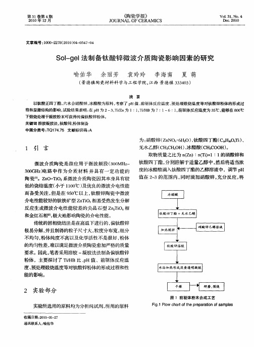
传统的固相烧结法是在高温下进行的, 偏钛酸锌 极易分解 , 并且制得的粒子尺寸大, 粒度分布宽, 组分 不均匀, 粉体纯度不高以及化学活性不是很好 , 粉体 的均匀性差 , 以满足微 波介 质 陶瓷愈加严格 的质量 难
要求 。因此 , 笔者采用溶 胶 一凝胶法 法制备偏钛 酸锌
粉体,主要探讨了 T/B比、H值 、前驱体反应温 i H p 度、 预处理煅烧温度等对钛酸锌粉体的形成过程和. 性 能 的影响 。
透 明凝胶 , 静置陈化 1h后 , 2 溶胶 转化 成凝 胶 , 凝胶 将
置 于 8 ℃下干燥 2 h 待 完全 变 干 后进 行 研磨 、 烧 0 4, 煅 处理 ;然后进 行造 粒 ,在 1MP 压 力 下压 片 ,选 择 0 a
9 0 1 5 ℃下煅烧 2小 时 。 5~ 00
将 预 烧 得 到 的 粉 体 用 德 国 Brk r公 司 的 ue D8 d ac 型 x 射 线 衍 射 仪 ( R 进 行 物 相 分 析 , A vne X D) 烧 成的陶 瓷选 用C — = . 0  ̄,选 用 日本 电子 u K , 1 46 5 公 司 (E ) JM一 7 0 J OL 的 S 6 0 F型 场 发 射 扫描 电镜 进 行
第 3 卷 第 4期 l 21 年 l 00 2月
《 瓷学 报》 陶
J OURNAL CERAM I 0F CS
Vo . 。 1 31 No. 4 De . 01 c2 0
文章 编号 :00 2 7 ( 00 0 _ 5 0 10 - 28 2 1 )4 o 4 4
S lg l 制备钛 酸锌微 波介质 陶瓷影 响 因素 的研 究 o— e 法
于钛 酸 四丁 酯的负 电性 烷氧 基 一 R, 金属离 子 T O 使 极 易受到 亲核攻 击 , 到水 后会立 即发 生水解和 聚合 遇 反 应 , 至 出现 T(H)沉 淀 , 坏溶 胶 体 系 的稳 定 甚 i O 破
Au-Pt
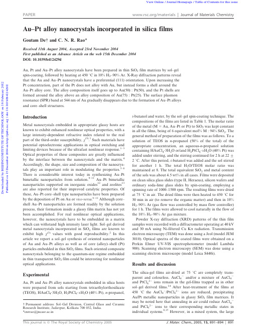
Au–Pt alloy nanocrystals incorporated in silica filmsGoutam De {and C.N.R.Rao *Received 11th August 2004,Accepted 23rd November 2004First published as an Advance Article on the web 15th December 2004DOI:10.1039/b412429dAu,Pt and Au–Pt alloy nanocrystals have been prepared in thin SiO 2film matrices by sol–gel spin-coating,followed by heating at 450u C in 10%H 2–90%Ar.X-Ray diffraction patterns reveal that the Au and Au–Pt nanocrystals have a preferential (111)orientation.Upon increasing the Pt concentration,part of the Pt does not alloy with Au,but instead forms a shell around the Au–Pt alloy core.The alloy composition itself goes up to Au(50):Pt(50),and the Pt shells are formed around the alloy above an alloy composition of Au(75):Pt(25).The surface plasmon resonance (SPR)band at 544nm of Au gradually disappears due to the formation of Au–Pt alloys and core–shell structures.IntroductionMetal nanocrystals embedded in appropriate glassy hosts are known to exhibit enhanced nonlinear optical properties,with a large intensity-dependent refractive index related to the real part of the third-order susceptibility,x (3).1Such materials have potential optoelectronic applications in optical switching and limiting devices because of the ultrafast nonlinear response.1–3Optical properties of these composites are greatly influenced by the interface between the nanocrystals and the matrix.4Accordingly,the shape,size and composition of the nanocrys-tals play an important role in modulating the properties.5–8There is considerable interest today in synthesizing Au–Pt bimetallic nanoparticles from solution.9–11Au–Pt bimetallic nanoparticles supported on inorganic oxides 12and zeolites 13are also reported for their improved catalytic properties.Of these,Au–Pt core–shell type nanoparticles have been prepared by the deposition of Pt on Au or vice-versa .9–11Although core–shell Au–Pt nanoparticles are formed readily by the solution process,their formation inside a glassy film matrix has not yet been accomplished.For real nonlinear optical applications,however,the nanocrystals have to be embedded in a matrix which can withstand high intensity laser light.Sol–gel derived metal nanocrystals incorporated in SiO 2films are known to exhibit high x (3)values with good reproducibility.2In this article we report a sol–gel synthesis of oriented nanoparticles of Au and Au–Pt alloys as well as of core (alloy)–shell (Pt)particles embedded in thin SiO 2films.Such oriented composite nanocrystals belonging to the quantum-size regime embedded in thin transparent SiO 2film could be interesting for nonlinear optical applications.ExperimentalAu,Pt and Au–Pt alloy nanocrystals embedded in silica hosts were prepared from sols starting from tetraethylorthosilicate (TEOS),HAuCl 4?3H 2O,H 2PtCl 6?x H 2O (40%Pt),n -propanol,i -butanol and water,by the sol–gel spin-coating technique.The compositions of the films are listed in Table 1.The molar ratio of the metal (M 5Au,Au–Pt or Pt)to SiO 2was kept constant in all the films,being of 6equivalent mol%M :94%SiO 2.The general method of preparation of the films was as follows.To a solution of TEOS in n -propanol (50%of the total)of the appropriate concentration,an aqueous-n -propanol solution containing HAuCl 4?3H 2O or/and H 2PtCl 6?x H 2O (40%Pt)was added under stirring,and the stirring continued for 2h at 22¡2u C.After this period,i -butanol was added and the sol stirred for another 1h.The total H 2O/TEOS molar ratio was maintained at 8.The total equivalent SiO 2and metal content of the sols was about 4.5wt%in all cases.Films were deposited on clean silica glass slides (type II,Heraeus),silicon wafers and ordinary soda-lime glass slides by spin-coating,employing a spinning rate of 1000–1500rpm.The resulting films were dried at 75u C in air.The dried films were then heated to 450u C for 30min in air (to remove the organic matter)and then in 10%H 2–90%Ar (gas flow was controlled by mass flow controller)for 1h.The films were allowed to cool naturally in the flow of the 10%H 2–90%Ar gas mixture.Powder X-ray diffraction (XRD)patterns of the thin film samples were recorded with a diffractometer operating at 40kV and 30mA using Ni-filtered Cu K a radiation.Transmission electron microscopy (TEM)was done using a Jeol (model JEM 3010).Optical spectra of the coated films were obtained on a Perkin Elmer UV-VIS spectrophotometer (model Lambda 900).Scanning electron microscopy (SEM)was done using a scanning electron microscope (model Leica S440i).Results and discussionThe silica-gel films air-dried at 75u C are completely trans-parent and colourless.AuCl 42and/or a mixture of AuCl 42and PtCl 622ions remain in the gel-films trapped as in other sol–gel derived films.14After heat-treatment of the films at 450u C the AuCl 42/PtCl 622ions are reduced,precipitating Au/Pt metallic nanoparticles in glassy SiO 2film matrices.It may be noted here that annealing in air could reduce AuCl 42and PtCl 622ions to their corresponding metallic states in individual systems.8,15However,in a mixed system,the large{Permanent address:Sol–Gel Division,Central Glass and Ceramic Research Institute,Jadavpur,Kolkata 700032,India.*cnrrao@jncasr.ac.inPAPER /materials |Journal of Materials ChemistryD o w n l o a d e d b y BE I J I N G I N S T I T U T E OF T E C H N O L OG Y o n 16 F e b r u a r y 2012P u b l i s h e d o n 15 D e c e m b e r 2004 o n h t t p ://p u b s .r s c .o r g | d o i :10.1039/B 412429DView Online / Journal Homepage / Table of Contents for this issueredox potential (+0.99V)of the AuCl 42ions could inhibit the reduction process of platinum ions.To avoid this complex situation,films were heated in a reducing atmosphere (H 2–Ar gas mixture),as was also followed by other workers for the preparation of supported Au–Pt bimetallic catalysts by reduction of the HAuCl 4/H 2PtCl 6mixture.12a ,13The heat-treated films are homogeneous and transparent.The film containing Au alone is reddish-blue in colour.The colour gradually disappears on increasing the Pt loading.The film containing Pt alone is light brown in colour.The thickness of the films,estimated by cross-sectional scanning electron microscopy (SEM)was in the 145–175nm range.As also pointed out earlier,one would expect that the gold ions are reduced first,followed by platinum ions since the standard redox potential E 0for the AuCl 42/Au 0couple is higher than that of the PtCl 622/Pt 0couple.9,16,17AuCl 42+3e 2«Au 0+4Cl 2E 05+0.99V PtCl 622+4e 2«Pt 0+6Cl 2E 05+0.74VAs a result,the Au nanoparticles form first and the Pt atoms are deposited on to the gold nanoparticles in the SiO 2film matrix.Transmission electron microscope (TEM)images of the Au and Au–Pt nanocrystals are shown in Fig.1.The images show the presence of trigonal or prismatic Au nanocrystals with a size range of 10–40nm [Fig.1(a)].The inclusion of Pt causes a drastic decrease in the size of the nanoparticles to 3–4nm.Interestingly,we observe the presence of a large number of bigger clusters in the case of Au 4.5Pt 1.5[Fig.1(b)],whereas in Au 3Pt 3the number of such big clusters is reduced [Fig.1(c)].In the case of Au 1.5Pt 4.5,the bigger clusters are absent [Fig.1(d)].Instead,we observe uniform-sized nanoparticles of 3–4nm.In Fig.2,we show the XRD patterns of the SiO 2films containing Au,Pt and Au–Pt alloy nanocrystals deposited on silica glass substrates.The patterns show only the (111)Bragg reflection,18indicating a highly oriented growth of the nanocrystals.The other Bragg reflections are hardly visible.The decrease in the d (111)value with increasing Pt loading is consistent with the formation of Au–Pt solid solutions (Table 1).Thus,in the case of Au the (111)reflection is at2.354A˚corresponding to a 50.4078nm,while in Au 4.5Pt 1.5it is at 2.344A˚corresponding to a 50.4060nm.The a value calculated from Vegard’s law for Au 0.75Pt 0.25(Au 4.5Pt 1.5)is 0.4060nm.19,20For Au 3Pt 3and Au 1.5Pt 4.5,the observed dvalues are at 2.339and 2.331A˚respectively corresponding to a values of 0.4051and 4037nm respectively.These values are higher,indicating a lower Pt content than indicated by the nominal composition of the solid solution (Table 1).In these cases,the a values calculated from Vegard’s law give thecompositions as Au 0.666Pt 0.333and Au 0.54Pt 0.46respectively.It appears that in the latter,a major proportion of the Pt atoms does not enter the alloy structure.It may be noted that bulk Au–Pt solid solutions are generally formed only at tempera-tures above 1100u C.The compositions of the alloys derived from the respective d values obtained from the XRD patterns are listed in Table 1.By simple arithmetic,we see that about 50and 66mol%of the Pt remains out of the solid solutions in Au 3Pt 3and Au 1.5Pt 4.5respectively.The XRD peaks in these systems should therefore show the Pt reflection as well.We,do not,however,see a peak due to Pt because of the small particle size (see Fig.2in the case of pure Pt).Fig.3shows the optical spectra of the films annealed at 450u C for 1h in 10%H 2–90%Ar.The pure Au film shows a band at 544nm with a broad tail extending towards higher wavelengths due to surface plasmon resonance (SPR).The SPR band of well-dispersed spherical Au nanocrystals is generally sharp and appears around 520nm.The broadening of this band at higher wavelengths may be due to the anisotropy of the trigonal/prismatic shape (non-spherical)of the Au nanocrystals.6,21The pure Pt film does not have aTable 1Composition of the films obtained after annealing at 450u C for 1h in 10%H 2–90%ArStarting composition(mol Au :mol Pt :mol Si)Sample name Composition (nominal)Lattice parameter/nm (XRD)Calculated alloy composition from Vegard’s law Cluster composition 6:0:94AuAu0.4078AuAu4.5:1.5:94Au 4.5Pt 1.5Au 0.75Pt 0.250.4060Au 0.75Pt 0.25Au 4.5Pt 1.53:3:94Au 3Pt 3Au 0.5Pt 0.50.4051Au 0.666Pt 0.333Au 3Pt 1.5core–Pt 1.5shell 1.5:4.5:94Au 1.5Pt 4.5Au 0.25Pt 0.750.4037Au 0.54Pt 0.46Au 1.5Pt 1.5core–Pt 3shell 0:6:94PtPt0.3924PtPtFig.1TEM images showing the nanoparticles embedded in SiO 2films:(a)Au,(b)Au 4.5Pt 1.5,(c)Au 3Pt 3and (d)Au 1.5Pt 4.5.The alloy compositions are nominal (see Table 1).D o w n l o a d e d b y BE I J I N G I N S T I T U T E OF T E C H N O L OG Y o n 16 F e b r u a r y 2012P u b l i s h e d o n 15 D e c e m b e r 2004 o n h t t p ://p u b s .r s c .o r g | d o i :10.1039/B 412429Ddistinguishable SPR band.The dampening of the Au SPR band due to the introduction of Pt indicates the formation of either a Au–Pt solid solution or a Au core–Pt shell type structure.Since the calculated and observed lattice parameters agree well in the case of Au 4.5Pt 1.5(Table 1),we suggest that this is a good solid solution rather than a Au core–Pt shell.For Au 3Pt 3and Au 1.5Pt 4.5,the optical spectra show that the Au-SPR band is very weak or absent.This observation may be taken to indicate either the formation of a Au–Pt solid solution or a Au core–Pt shell type structure.However,in Au 3Pt 3,the a value calculated from Vegard’s law gives the composition of the alloy to be Au 0.666Pt 0.333showing that about 50mol%of the Pt remains outside the Au–Pt alloy.Similarly,in the case of Au 1.5Pt 4.5,the d (111)value is consistent with formation ofthe Au 0.54Pt 0.46core with about 66%of the Pt remaining as the shell.The core–shell type structure is shown schematically in Fig.4.It is of interest to know whether the Au,Au–Pt alloy and Pt nanoparticles remain as separate clusters in the thin film silica matrix.It was pointed out earlier that the Au nanoparticles are formed first,with the Pt atoms precipitating on to the gold nanoparticles.The Pt atoms close to the Au atoms would be expected to form solid solutions under the experimental conditions.When the Pt concentration is low (as in Au 4.5Pt 1.5),we obtain only a Au–Pt solid solution while in Au 3Pt 3and Au 1.5Pt 4.5part of the Pt forms a solid solution with the Au,the remaining part forming a shell around the alloy.The deposition of Pt atoms on to the surface of the gold nanoparticles can be understood from the optical spectra of the composite films as well.A significant dampening of the gold surface plasmon resonance is known to occur by a surface layer of platinum.9–11This is clearly evidenced in the absorption spectra of the annealed films shown in Fig. 3.The SPR band of gold (544nm)gradually disappears with increasing Pt content.If a mixture of discrete Au and Pt nanoparticles were present,the Au SPR band would continue to occur in the Au–Pt films.ConclusionsAu,Au–Pt alloys and core (alloy)–shell (Pt)nanoparticles have been generated in glassy silica films by the sol–gel method.The nanoparticles are oriented in the (111)crystalline plane.By the low-temperature method employed,nanocrystal alloys are formed up to a Au :Pt ratio of about 1:1,but with an increase in Pt content,Pt shells are formed around the alloy cores.Formation of Au,Pt and their alloy nanoparticles in the silica film matrix is noteworthy and could be of potential technological value.Goutam De {and C.N.R.Rao *Chemistry and Physics of Materials Unit,Jawaharlal Nehru Centre for Advanced Scientific Research,Jakkur P.O.,Bangalore 560064,India.E-mail:cnrrao@jncasr.ac.inReferences1H.Hache,D.Ricard and C.Flytzanis,J.Opt.Soc.Am.B ,1986,3,1647; C.Flytzanis, F.Hache,M. C.Klein, D.Ricard and Ph.Roussignol,Prog.Opt.,1991,29,321;T.Tokizaki,A.Nakamura,S.Kaneko,K.Uchida,S.Omi,H.Tanji and Y.Asahara,Appl.Phys.Lett.,1994,65,941.2G.De,L.Tapfer,M.Catalano,G.Battaglin, F.Caccavale,F.Gonella,P.Mazzoldi and R.F.Haglund,Jr.,Appl.Phys.Lett.,1996,68,3820andP.P.Kiran,G.De and D.N.Rao,IEE Proc.-Circuits Devices System ,2003,150,559.3Y.-P.Sun,J. E.Riggs,K. B.Henbest and R. B.Martin,J.Nonlinear Opt.Phys.Mater.,2000,9,481.Fig.2XRD patterns of nanocrystals of Au,Pt and Au–Pt alloys embedded in SiO 2thin film matrices.Nominal compositions of the alloys are shown (see Table1).Fig.3Optical absorption spectra of Au,Pt and Au–Pt alloys embedded in SiO 2thin filmmatrices.Fig.4Schematic diagram of a core (Au–Pt alloy)–shell (Pt)nanocrystal.D o w n l o a d e d b y BE I J I N G I N S T I T U T E OF T E C H N O L OG Y o n 16 F e b r u a r y 2012P u b l i s h e d o n 15 D e c e m b e r 2004 o n h t t p ://p u b s .r s c .o r g | d o i :10.1039/B 412429D4P.N.Butcher and D.Cotter,The Elements of Nonlinear Optics ,Cambridge University Press,Cambridge,UK,1990;J.A.Creighton and D.G.Eadon,J.Chem.Soc.,Faraday Trans.,1991,87,3881;F.Gonella,G.Mattei,P.Mazzoldi,G.Battaglin,A.Quaranta,G.De and M.Montecchi,Chem.Mater.,1999,11,814;R.H.Doremous,Langmuir ,2002,18,2436.5U.Kreibig and M.Volmer,Optical Properties of Metal Clusters ,Springer-Verlag,Berlin,1995.6 A.I.Kirkland, D. A.Jefferson, D.G.Duff,P.P.Edwards,I.Gameson,B.F.G.Johnson and D.J.Smith,Proc.R.Soc.London,Ser.A ,1993,440,589.7 C.N.R.Rao,G.U.Kulkarni,P.J.Thomas and P.P.Edwards,Chem.Eur.J.,2002,8,29.8G.De,G.Mattei,P.Mazzoldi, C.Sada,G.Battaglin and A.Quaranta,Chem.Mater.,2000,12,2157.9L.M.Liz-Marza ´n and A.P.Philipse,J.Phys.Chem.,1995,99,15120.10 C.Damle,K.Biswas and M.Sastry,Langmuir ,2001,17,7156.11 A.Henglein,J.Phys.Chem.B ,2000,104,2201.12(a )A.Va ´zquez-Zavala,J.Garcı´a-Go ´mez and A.Go ´mez-Corte ´s,Appl.Surf.Sci.,2000,167,177;(b )ng,S.Maldonado,K.J.Stevenson and B.D.Chandler,J.Am.Chem.Soc.,2004,126,12949.13G.Riahi,D.Guillemot,M.Polisset-Thfoin,A.A.Khodadadi and J.Fraissard,Catal.Today ,2002,72,115.14G.De and D.Kundu,Chem.Mater.,2001,13,4239.15H.Kozuka,G.Zhao and S.Sakka,J.Sol–Gel Sci.Technol.,1994,2,741;G.Fo ´ti,C.Mousty,K.Novy,ninellis and V.Reid,J.Appl.Electrochem.,2000,30,147.16R.C.Weast,Handbook of Chemistry and Physics,56th edn.,CRC Press,Cleveland,OH,1975,p.D-141.17 A.I.Vogel,Quantitative Inorganic Analysis,3rd edn.,Addison Wesley Longman Ltd,England,1961,p.87.18 D. F.Leff,L.Brandt and J.R.Heath,Langmuir ,1996,12,4723.19M.Hansen,Constitutions of Binary Alloys ,McGraw-Hill,New York,1958.20H.Okamoto, D.J.Chakrabarti, D. ughlin and T. B.Massalski,Phase Diagrams of Binary Gold Alloys,Monograph Series of Alloy Phase Diagrams ,ASM Internationals,Metals Park,OH,1987.21G.De and C.N.R.Rao,J.Phys.Chem.B ,2003,107,13597.D o w n l o a d e d b y BE I J I N G I N S T I T U T E OF T E C H N O L OG Y o n 16 F e b r u a r y 2012P u b l i s h e d o n 15 D e c e m b e r 2004 o n h t t p ://p u b s .r s c .o r g | d o i :10.1039/B 412429D。
溶胶-凝胶法ZnO薄膜的制备及性能表征

溶胶-凝胶法ZnO薄膜的制备及性能表征辛春雨;张继德;刘成有;蒋大勇;秦杰明【摘要】Zinc oxide thin films were synthesized on glass substrates by means of sol-gel method. The X-ray diffraction (XRD) results show that the grain size increased with the increasing of annealing temperature, which was confirmed .by the morphology by atomic force microscopy (AFM). The UV-Vis results show that there is a stronger absorption on the near band edge of zinc oxide and the bandgap of the film at 600 °C by means of annealing treatment is 3. 23 eV. Room-temperature photoluminescence (PL) results show that all films show UV emission peak at 386. 5 nm, the deep level emission is restrained by the increase of annealing temperature.%采用溶胶-凝胶法在玻璃衬底上制备ZnO薄膜,X射线衍射(XRD)结果表明:晶粒尺寸随退火温度的升高而增大,与原子力显微镜( AFM)分析薄膜表面形貌的结果相符;UV-Vis吸收谱线表明,在ZnO带边吸收的位置出现较强的吸收,并得到600℃退火处理的薄膜禁带宽度为3.23 eV;室温光致发光谱表明,所有薄膜均在386.5 nm处出现一个紫外发射峰,当退火温度升高时,深能级发射受到抑制.【期刊名称】《吉林大学学报(理学版)》【年(卷),期】2012(050)001【总页数】4页(P122-125)【关键词】溶胶-凝胶法;ZnO薄膜;光学性能【作者】辛春雨;张继德;刘成有;蒋大勇;秦杰明【作者单位】白城师范学院物理系,吉林白城137000;白城师范学院物理系,吉林白城137000;通化师范学院物理系,吉林通化134001;长春理工大学材料科学与工程学院,长春130022;长春理工大学材料科学与工程学院,长春130022【正文语种】中文【中图分类】TN814氧化锌(ZnO)是一种宽禁带Ⅱ-Ⅵ族直接带隙半导体材料, 室温下禁带宽度为3.37 eV, 具有六角形纤锌矿结构, 晶格常数a=0.325 nm, c=0.52 nm, 室温下的激子束缚能为60 meV[1-2]. ZnO作为一种新型功能材料, 具有优异的光学、电学、化学和热学稳定性, 在紫外发射器件和紫外激光器件等领域具有广阔的应用前景[3-5]. 目前, ZnO薄膜的制备方法包括分子束外延(MBE)法、射频磁控溅射(RF)法、脉冲激光沉积(PLD)法、金属有机物化学气相沉积(MOCVD)法和溶胶-凝胶(sol-gel)法等[6-7], 其中sol-gel法的制备工艺简单、成本低、膜厚均匀, 易于在任意形状的基体上大面积成膜. 本文采用sol-gel法在玻璃衬底上制备ZnO薄膜, 并分析了不同退火温度处理对其结构、表面形貌和光学性能的影响.1 实验1.1 薄膜的制备选用二水合乙酸锌(Zn(CH3COO)2·2H2O)作为前驱体, 无水乙醇作为溶剂, 单乙醇胺作为稳定剂, 所用试剂均为分析纯. 称取定量的Zn(CH3COO)2·2H2O溶于无水乙醇中, 溶液中金属离子浓度为0.45 mol/L, 加入与Zn2+等量的单乙醇胺, 同时滴入适量冰醋酸, 于70 ℃恒温充分搅拌2 h, 即得到性能稳定、无色透明的ZnO溶胶, 将溶胶静置陈化2 d待用.将玻璃基片(15 mm×15 mm)置于饱和重铬酸洗液中浸泡30 min后, 分别在丙酮、无水乙醇和去离子水中超声清洗10 min, 烘干后置于3 000 r/min匀胶机上涂膜30 s, 反复涂膜8次(每次涂膜后置于100 ℃恒温干燥箱中干燥5 min)即得到一定厚度的干凝胶薄膜, 再将干凝胶薄膜置于马弗炉中进行退火处理, 退火温度分别为300,400,500,600 ℃, 保温4 h, 自然冷却至室温, 即得到厚度约为1 μm 的ZnO薄膜.1.2 薄膜的表征采用日本Rigaku公司生产的D/max2500型旋转Cu靶(λ=0.1542 nm)X射线衍射仪测试薄膜的晶体结构, 管压40 kV, 管流100 mA, 扫描角度(2θ)为20°~80°; 采用美国Varian公司生产的Cary-50型紫外-可见分光光度计测量吸收光谱, 扫描速率600 nm/min, 扫描步长1 nm; 采用美国Jobin Yvon公司生产的Traix320型光谱仪测量光致发光(PL)谱, 微区光致发光选用波长为325 nm、功率为50 mW的He-Cd激光器作为激发光源.2 结果与讨论图1 不同退火温度下制备ZnO薄膜的XRD谱Fig.1 XRD patterns of ZnO thin films at different annealing temperatures2.1 薄膜的晶体结构与形貌不同退火温度下制备ZnO薄膜的XRD谱如图1所示. 由图1可见, 该薄膜均出现衍射晶面分别为(100),(002),(101),(102),(110),(103),(200),(112),(201)的衍射峰, 与体相ZnO标准值相符, 且在(100),(002)和(101)方向上, 分别在2θ=31.68°,34.34°,36.18°处出现3个明显的ZnO峰, 表明退火后的ZnO具有多晶六角纤锌矿结构; 随着退火温度的升高, 各衍射峰的强度增加, 半峰宽减小, 由Scherrer公式[8]可得ZnO薄膜的晶粒尺寸, 结果列于表1. 其中: D为颗粒平均尺寸; B为衍射峰的半高宽; θB为Bragg衍射角; λ=0.154 2 nm. 由表1可见, 随着退火温度的升高, ZnO晶粒开始生长, 粒径平均尺寸增大.表1 不同退火温度下ZnO薄膜的晶粒尺寸Table 1 Crystalline grain size ofZnO thin films at different annealing temperatures退火温度/℃ B/(°)θB/(°)晶粒尺寸/nm3000.16534.34564000.134.34825000.09534.34866000.0734.36118不同退火温度下ZnO薄膜的原子力显微镜(AFM)照片如图2所示. 由图2(A)可见, 300 ℃退火处理的薄膜晶粒尺寸均匀, 粒径约为40 nm, 晶界较模糊; 由图2(B)可见, 400 ℃退火处理的薄膜晶粒开始生长, 但晶粒尺寸不均匀, 粒径为40~100 nm, 晶界逐渐清晰; 由图2(C)可见, 500 ℃退火处理的薄膜粒径为40~130 nm, 薄膜表面粗糙度增加; 由图2(D)可见, 600 ℃退火处理的薄膜晶界清晰, 晶粒尺寸均匀, 粒径为70~150 nm, 表面粗糙度降低. 400,500,600 ℃退火处理的薄膜均出现明显沟壑状表面形貌, 这是由于涂膜不均匀或玻璃基片表面不平整所致.图2 不同退火温度下ZnO薄膜的AFM照片Fig.2 AFM images of ZnO thin films at different annealing temperatures2.2 吸收光谱分析不同退火温度下ZnO薄膜的吸收光谱如图3所示, 测量中用未涂膜的玻璃基片作为参考. 由图3可见, 薄膜在可见光区吸收较少, 但在对应ZnO 带边吸收位置有较强的吸收, 吸收阈值位于380 nm处.作为直接带隙半导体材料, ZnO薄膜的吸收系数和光子能量满足[9]:(αhν)=A(hν-Eg)1/2,其中: A为常数; α为吸收系数; hν为激发能; Eg为禁带宽度.600 ℃退火温度下ZnO薄膜吸收谱的光学带隙如图4所示. 由带边吸收的线性拟合可得薄膜的禁带宽度为3.23 eV. 该值小于单晶和多晶ZnO材料的禁带宽度, 这是由于在薄膜生长过程中, 趋于完整结晶状态的ZnO晶体在过高退火温度下, 晶体内部重新产生缺陷所致.图3 不同退火温度下ZnO 薄膜的吸收谱Fig.3 Optical absorbtion spectra of ZnO thin films at different annealing temperatures图4 600 ℃退火温度下ZnO薄膜吸收谱的光学带隙Fig.4 Optical bandgapof absorbtion spectrum of ZnO thin film at 600 ℃2.3 室温下光致发光光谱分析不同退火温度下ZnO薄膜的光致发光(PL)谱如图5所示. 由图5可见, 所有薄膜发光均由386.5 nm附近的紫外发光和516 nm附近的绿光发光组成. 其中ZnO的紫外光来源于激子发光, 绿光来源于ZnO薄膜内部的不同缺陷(锌缺陷、氧缺陷、锌间隙和氧间隙等)以及界面缺陷发光[10]. 为便于对比, 本文将各光谱强度进行归一化处理, 并计算了深能级发光强度(Id)与紫外发光强度(Ie)之比, 其与退火温度的关系如图6所示. 由图6可见, 随着退火温度的升高, Id与Ie比值逐渐减小, 表明随着退火温度的升高, 深能级发射受到抑制而紫外发射得到加强, 即ZnO中缺陷减少, 从而提高了薄膜结晶质量, 与XRD结果相符. 与文献[11-13]结果比较可见, 利用该工艺制备薄膜, 通过调节温度参数, 可抑制ZnO深能级发射, 从而提高紫外发射.综上, 本文采用溶胶-凝胶法在玻璃衬底上制备了ZnO薄膜, 并利用X射线衍射仪、原子力显微镜、紫外-可见分光光度计和荧光光谱仪对其结构、表面形貌和光学性能进行了分析. 结果表明: ZnO薄膜具有多晶六角纤锌矿结构, 结晶程度较高, 晶粒尺寸随退火温度的升高而增大; 薄膜在可见光区吸收较少, 在对应ZnO带边吸收的位置吸收较强, 吸收阈值位于380 nm附近, 由带边吸收的线性拟合可得薄膜的禁带宽度为3.23 eV; 所有薄膜均在386.5 nm处出现一个紫外发射峰和516 nm附近的深能级发光峰, 且随退火温度的升高, 深能级发光强度与紫外发光强度的比值逐渐减小, 表明随退火温度的升高, ZnO晶体中缺陷减少, 从而提高了薄膜的结晶质量.图5 不同退火温度下ZnO薄膜的光致发光(PL)谱Fig.5 PL spectra of ZnO thin films at different annealing temperatures图6 Id/Ie与退火温度的关系Fig.6 Relationship of Id/Ie with theannealing temperature参考文献[1] ZHAO Dong-xu, LIU Yi-chun, SHEN De-zhen, et al. Structure and Photoluminescence Properties of ZnO Microrods [J]. J Appl Phys, 2002,94(9): 5605-5608.[2] CHEN Yu-feng, JIANG Feng-yi, WANG Li, et al. Structural and Luminescent Properties of ZnO Epitaxial Film Grown on Si(111) Substrate by Atmospheric-Pressure MOCVD [J]. Journal of Crystal Growth, 2005, 275(3/4): 486-491.[3] Abrarov S M, Yuldashev S U, Kim T W, et al. Effect of Photonic Band-Gap on Photoluminescence of ZnO Deposited Inside the Green Synthetic Opal [J]. Optics Communications, 2005, 250(1/2/3): 111-119.[4] YANG Jing-hai, GAO Ming, ZHANG Yong-jun, et al. Synthesis and Optical Properties of Ce-Doped ZnO [J]. Chem Res Chinese Universities, 2008, 24(3): 266-269.[5] Fan X M, Lian J S, Guo Z X, et al. ZnO Thin Film Formation on Si (111) by Laser Ablation of Zn Target in Oxygen Atmosphere [J]. Journal of Crystal Growth, 2005, 279(3/4): 447-453.[6] Singh Sukhvinder, Srinivasa R S, Major S S. Effect of Substrate Temperature on the Structure and Optical Properties of ZnO Thin Films Deposited by Reactive RF Magnetron Sputtering [J]. Thin Solid Films, 2007, 515(24): 8718-8722.[7] Gao X D, Li X M, Yu W D. Structural and Morphological Evolution of ZnO Cluster Film Prepared by the Ultrasonic Irradiation Assisted Solution Route [J]. Thin Solid Films, 2005, 484(1/2): 160-164.[8] LIN Wei, MA Rui-xin, SHAO Wei, et al. Structural, Electrical and Optical Properties of Gd Doped and Undoped ZnO∶Al (ZAO) Thin Films Prepared by RF Magnetron Sputtering [J]. Applied Surface Science, 2007, 253: 5179-5183.[9] YE Zhi-zhen, LÜ Jian-guo, CHEN Han-hong, et al. Preparation and Characteristics of p-Type ZnO Films by DC Reactive Magnetron Sputtering [J]. Journal of Crystal Growth, 2003, 253(1/2/3/4): 258-264.[10] Bagnall D M, Chen Y F, Shen M Y, et al. Room Temperature Excitonic Stimulated Emission from Zinc Oxide Epilayers Grown by Plasma-Assisted MBE [J]. Journal of Crystal Growth, 1998, 184/185: 605-609.[11] CHEN Nai-bo, QIU Dong-jiang, WU Hui-zhen, et al. Comparison of Ultraviolet Photoluminescence Characteristics between MgZnO and ZnO Thin Films [J]. J Infrared and Millimeter Waves, 2003, 22(5): 349-352. (陈奶波, 邱东江, 吴惠桢, 等. MgZnO和ZnO晶体薄膜紫外发光特性比较 [J]. 红外与毫米波学报, 2003, 22(5): 349-352.)[12] WU Li-li, WU You-shi, PAN Xiao-ru, et al. Synthesis of ZnO Nanorod and the Annealing Effect on Its Photoluminescence Property [J]. Optical Materials, 2006, 28(4): 418-422.[13] Ursaki V V, Tiginyanu I M, Zalamai V V, et al. Photoluminescence and Resonant Raman Scattering from ZnO-Opal Structures [J]. Journal of Applied Physics, 2004, 96(2): 1001-1006.。
溶胶凝胶法的英文

Sol-Gel Method: A Versatile Techniquefor Materials ScienceThe sol-gel method, a versatile and widely used technique in materials science, has gained significant attention due to its unique capabilities in synthesizing a diverse range of materials with precise control over their microstructure and properties. Originating from the early 19th century, the sol-gel process has evolved over time, becoming a key method for the preparation of ceramics, glasses, and more recently, nanocomposite materials.The sol-gel method involves the chemical transformation of a liquid precursor, known as the sol, into a solid material through a series of controlled reactions. This transformation occurs through the hydrolysis and condensation of the precursor molecules, resulting in the formation of a three-dimensional network that eventually gels and solidifies. The key advantages of this technique include its ability to produce materials with high purity, fine control over particle size and morphology, and the potential for scalability and cost-effectiveness.The success of the sol-gel process depends criticallyon several parameters, including the selection of the appropriate precursor, the choice of solvents and catalysts, and the control of reaction conditions such as temperature and pH. These factors determine the rate and mechanism of the hydrolysis and condensation reactions, thereby influencing the structure and properties of the final material.One of the most significant applications of the sol-gel method is in the preparation of oxide-based materials, such as ceramic coatings and thin films. The precision withwhich the method allows for the control of themicrostructure of these materials has led to their widespread use in various industries, including electronics, energy, and aerospace. Additionally, the sol-gel technique has been extended to the preparation of composite materials, nanocomposites, and even biomaterials, further expandingits scope and impact.In recent years, the sol-gel method has also gained popularity in the field of nanotechnology, where it is used to synthesize nanoparticles and nanofibers with uniqueoptical, electrical, and mechanical properties. These materials have the potential to revolutionize various fields, including medicine, energy storage, and environmental remediation.In conclusion, the sol-gel method represents a powerful tool in materials science, offering precise control over the microstructure and properties of a wide range of materials. Its versatility, scalability, and cost-effectivenesss have made it a favorite among researchers and industries alike, and its potential for further development and innovation remains exciting.**溶胶凝胶法:材料科学中的多功能技术**溶胶凝胶法作为材料科学中的一种多功能且广泛应用的技术,因其对合成材料的微观结构和性质的精确控制而备受关注。
溶胶凝胶法制备ZnO薄膜的成核生长和失稳分解研究
溶胶凝胶法制备ZnO薄膜的成核生长和失稳分解研究臧竞存 1 田战魁1刘燕行2迟静1邹玉林1魏建忠 1 叶建萍3.(1北京工业大学材料科学与工程学院,2北京工业大学环境与能源工程学院,北京100022,3中国科学院化学所光化学重点实验室,北京100080)E-mail:zangjc@.摘要:采用溶胶-凝胶法在ZnWO4单晶上制备出透明的ZnO薄膜。
通过光学显微镜观察了ZnO 薄膜的表面形貌。
实验结果表明:ZnO薄膜的形成经历了表面成核,晶粒长大和岛的形成三个不同的阶段。
由于ZnO晶核是在非平衡条件下生长的,在生长过程中不可避免地出现了枝晶生长和分形生长以及失稳分解。
关键词:氧化锌薄膜,成核,枝晶生长,分形生长,失稳分解1. 引言ZnO是一种重要的功能材料和Ⅱ-Ⅵ族直接宽带半导体材料,具有良好的机电耦合性能。
室温时禁带宽度为3.37eV,激子束缚能为60meV。
由于这些优异的物理化学性质,使其在光电导,压电,光波导,发光器件,激光器,透明导电薄膜,气敏传感等领域有广泛的应用。
特别是它可制作蓝光或紫外光发光二极管(LED)和激光二极管(LD),引起人们极大的兴趣[1,2]。
ZnO是一致熔融化合物,熔点为1975℃。
高温下ZnO的挥发性很强,不能采用提拉法生长工艺获得ZnO单晶[3]。
近年来有文献报道,籽晶诱导成核的气相生长方法已经获得直径50mm的ZnO单晶[4],水热合成法和助熔剂法[5]也生长出厘米级晶体,但是商业化生产ZnO单晶还存在许多问题。
由于ZnO体单晶生长困难,价格昂贵,尺寸小,难于满足各种应用的需要。
因此,对各种ZnO薄膜制备技术的研究和开发成为ZnO材料及器件应用研究的一个重要方向。
到目前为止,人们已经采用多种方法制备出高质量的ZnO薄膜,并对ZnO薄膜的结构,发光性能和表面形貌作了大量的报道,但对ZnO薄膜的形貌及其形成过程报道较少。
本文采用溶胶-凝胶法,ZnWO4单晶为衬底,观察和研究了ZnO薄膜的成核生长与失稳分解、枝晶与分形形态。
sol-gel方法。。

Enhanced photo-induced hydrophilicity of the sol –gel-derived ZnO thin films by Na-doping (溶胶凝胶法制得的钠掺杂的ZnO 薄膜的光诱导亲水性)摘要:具有不同钠/锌比值的钠掺杂ZnO 薄膜采用溶胶凝胶法制得。
薄膜的微观结构,化学成分,表面形貌,以及薄膜的可湿性可通过X -射线衍射,X 射线光电子能谱(XPS ),扫描电镜和水接触角装置进行观察。
薄膜的润湿性和钠 /锌比值关系已详细研究。
通过交替紫外线水性随着薄膜钠/锌比值增加到高达0.08,然后下降。
该机制可能是由于表面纳米结构和钠的掺杂浓度诱导。
通过溶胶凝胶法在石英玻璃和硅衬底上生长钠掺杂的ZnO 薄膜钠掺杂氧化锌薄膜制备方法:乙二醇甲醚和乙醇胺分别被用作溶剂和稳定剂。
二水醋酸锌(Zn(CH3COO)2·2H2O )在室温下溶解于乙二醇甲醚和乙醇胺混合物中。
乙醇胺和醋酸锌的摩尔比为1:1,醋酸锌浓度为0.5 mol/ L 。
不同数量的氯化钠被加到上述的溶解物中,钠/锌的原子比分别为0,0.02,0.04,0.08和0.10(这些薄膜分别命名为氧化锌,氧化锌:钠 2%,氧化锌:钠 4%,氧化锌:钠8%,与ZnO :Na 10%)。
溶解物在60◦ç被搅拌120分钟,在此过程中使用磁力搅拌器来获得清晰,均匀透明溶胶,作为溶胶涂层后维持一天。
石英玻璃和硅被用来作为衬底。
氧化锌薄膜通过一个转速为3000rpm 自旋涂层法自旋30秒获得。
凝胶薄膜在150◦C 温度下被干燥10分钟,此过程重复10次。
这些涂层薄膜在800◦C 的空气中退火处理60分钟。
第一步:获得溶解物第二步:二水醋酸锌(Zn(CH3COO)2·2H2O) 溶解 乙二醇甲醚和乙醇胺混合物乙醇胺和醋酸锌的摩尔比为1:1,醋酸锌浓度为0.5 mol/ L2、Effects of substrates and seed layers on solution growing ZnO nanorods (衬底和籽晶层对熔融法制的ZnO 纳米棒的影响)摘要:定向ZnO 纳米棒通过二阶段法制得,包括低温条件下在硝酸锌和六次甲基四胺水溶液中不同衬底籽晶层的合成和氧化锌纳米棒的生长。
微乳液结合Sol-Gel法制备纳米ZnTiO_3及其表征
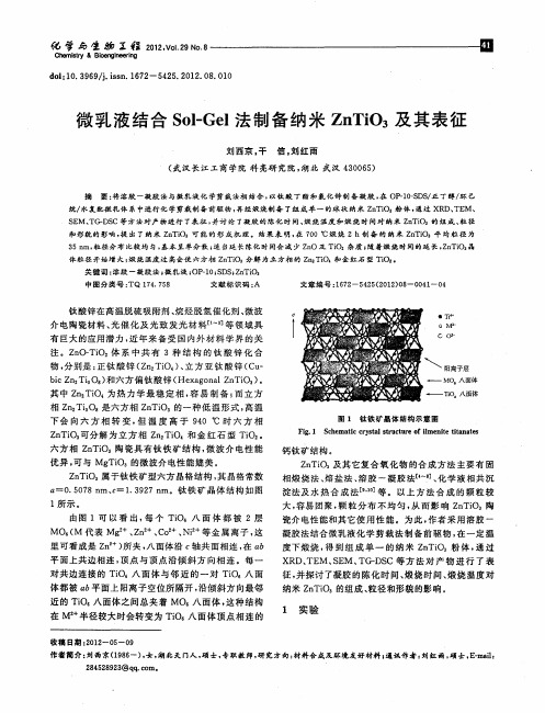
一
T 6八面体 i 0
图 1 钛 铁 矿 晶 体 结 构 示 意 图
Fi.1 S h m ai r sa tu t r fime t ia ts g ce tc c y t lsr c u e o l nie ttna e
亿 擘 与 生 劬 Z程 21,o2 N. 02VI9 o8 .
Ch m i r & Bi e g n er g e sy t o n ie i n
d i1 . 9 9ji n 1 7 - 5 2 . 0 2 0 . 1 o :0 3 6 / s . 6 2 4 5 2 1 . 8 0 0 . s
微 乳液 结 合 S l l o- 法制 备 纳米 Z T O 及 其表征 Ge n i3
刘西京 。 干 信 , 红 雨 刘
( 汉长 江工 商学院 科 亮研 究院 , 武 湖北 武 汉 4 0 6 ) 3 0 5
摘 要 : 溶 胶 一 凝胶 法 与微 乳 液 化 学剪 裁 法相 结 合 , 将 以钛 酸 丁 酯 和 氯化 锌 制 备 凝 胶 , 0 -OS S . 醇/ 己 在 p I-D /  ̄丁 环
平 面上共 边相连 , 点 与顶 点沿 倾 斜 方 向相 连 。每 一 顶 对共 边连 接的 T 0 i 八 面体 与 邻 近 的 一 对 Ti 八 面 O
体都 被 n 平 面上 阳离子空位 所隔开 , 6 沿倾 斜方 向最邻 近 的 Ti s O 八面 体之 间总夹 着 MO 八 面 体 , 。 这种 结 构 在 M。 半径较 大时会转 变 为 T O 八 面 体顶 点 相连 的 i
纳米晶钛酸钡的Sol_gel法制备及其尺寸效应
!
!) <
结果与讨论
#$% 分析 图 ! 为不同温度退火 2 K 的样品的 LD3 谱图I 经 LD3 谱图分析可知,样品 . 经 "#* % 退火 2 K 后, 粉末样品中有部分 =’<、 M7<2 及 =’5<N 相存在 I 经 )#* % 处理后,出现单一的钙钛矿相钛酸钡微 晶 I 图 2 为不同 2 ! 扫描范围的 =’M7<N 的精细 LD3 谱I 室温下铁电四方相钛酸钡 , 在 N- Q H*R之间 (!!!) 可观测到一个衍射峰, 对应 面; 在 HN Q H)R之
B CD!( E
晶胞存在,6C 1: 的钛酸钡纳米晶为顺电立方相结 构,这与 JIK 的结果基本一致 & 其余三峰的依然 在立方 存在, 可用有序 D 无序的相变模型来解释 BH E , 相,)/ 原子并非位于原胞中心不动,而是等几率地 沿着体对角线的方向作无序运动, 长时间来看仍保 持 ?& 点群对称性, 但某一时刻, 对称性下降, 非拉 曼活性模转变为拉曼活性 & "* ) +,- 分析 图 @ 为不同粒径钛酸钡的升温 KLM 曲线,其 中 * 曲线为 !’( 1: 的钛酸钡的升温 KLM 曲线,其
!"#$ %&’() *+&,-) .,/) 0 123, 42$526 7268$9 !" !""# 表! )*+%, !
@PN HF( CF( QF( !(F( !’(( B P 1: 6C F@ H" !(’ !’(
#$%& ’(
不同温度退火 " # 的 $%&’() 纳米晶的晶胞参数
)-, %*../0, 0$12.*1.2 $3 4*)/56 7,% *11,*%,8 *. 8/33,9,1. .,:;,9*.<9,2 3$9 ’ ’ ! = !!! ? P = O ? 6C& Q!@ 6C& Q6H 6C& QF( 6C& QH! 6C& Q"6 ’ ! = ’(( ? P = O ? @F& ’(F @F& 6(F @F& @!" @F& F(H @F& @FQ $ P ;: @((& C’ 6QQ& QC 6QQ& (F 6QC& 6( 6QC& H( " P ;: 6QQ& Q’ @((& Q6 @(’& @( @(6& 6! @(’& H@ C = !!! ? P ;: ’6!& ’@ ’6!& !! ’6!& (6 ’6(& Q! ’6(& Q" "D $ (& QQHC !& ((’@ !& ((C@ !& (!’" !& (!(!
溶胶-凝胶法制备Co掺杂ZnO稀磁半导体的结构研究
溶胶-凝胶法制备Co掺杂ZnO稀磁半导体的结构研究赵维佳吉林师范大学物理学院 2006级3班 0608302指导教师:刘惠莲(副教授)摘要:稀磁半导体(DMSs)集电子的电荷和自旋于一体,使之具有了半导体的电荷输运特性和磁性材料的信息存储特性,是一种新型的功能材料。
本实验采用溶胶—凝胶法制备了钴掺杂氧化锌稀磁半导体Zn1-xCoxO,利用X射线衍射仪(XRD),拉曼(Raman)、X射线光电子能谱仪(XPS),X射线吸收精细结构(XAFS)研究样品结构性质。
结果表明:利用溶胶凝胶法制备Zn1-xCoxO样品,700℃为其最佳的烧结温度。
所有样品为六角纤锌矿结构,并能形成稳定复合晶体。
关键词:稀磁半导体;ZnO;结构Structure of Co doped ZnO dilued magnetic semiconductors by sol-gel methodZhao Weijia,Jilin Normal University, College of Physics, Class 3 Grade 2006,0608302Instructor : Liu Huilian ( Associate Professor)Abstract :Diluted magnetic semiconductor (DMSs) set of electronic charge and spin in one, so that it has a charge transport properties of semiconductor and magnetic properties of information storage, and it is a new functional materials. In this experiment, sol - gel cobalt doped ZnO diluted magnetic semiconductor Zn1-xCoxO, X-ray diffraction (XRD), Raman (Raman), X-ray photoelectron spectroscopy (XPS), X-ray absorption fine structure (XAFS) takes advantage of studying structural propertiesof the sample. The results showed that: The sol-gel Zn1-xCoxO samples, 700℃ for the best sintering temperature. All samples are hexagonal structure, and can form a stable complex crystals.Keywords:diluted magnetic semiconductor;ZnO; structure1 引言稀磁半导体(Diluted Magneic Semiconductors,简写为DMSs)是一种新型的功能材料,它是指磁性过渡金属或稀土金属离子部分取代化合物半导体(通常为AB型)的阳离子,从而能形成同时利用电子的电荷属性和自旋属性进行信息处理和存储的具有磁性材料和半导体材料双重特性的三元或四元化合物。
氨水对溶胶-凝胶法制备硅溶胶粒径及稳定性的影响
第42卷第7期2023年7月硅㊀酸㊀盐㊀通㊀报BULLETIN OF THE CHINESE CERAMIC SOCIETY Vol.42㊀No.7July,2023氨水对溶胶-凝胶法制备硅溶胶粒径及稳定性的影响熊江敏1,段㊀宁1,陆成龙2,3,张银凤2,李崇瑞1(1.武汉科技大学资源与环境工程学院,武汉㊀430081;2.湖北理工学院矿区环境污染控制与修复湖北省重点实验室,黄石㊀435003;3.湖北理工学院先进材料制造与固废资源化协同技术湖北省工程研究中心,黄石㊀435003)摘要:本文以正硅酸乙酯(TEOS)为原料,在以氨水为催化剂的碱体系中,采用溶胶-凝胶法制备了二氧化硅溶胶㊂通过SEM-EDS㊁XRD㊁热重分析㊁激光粒度分析㊁Zeta 电位等分析手段,研究了氨水的加入量对二氧化硅溶胶粒径以及稳定性的影响㊂研究结果表明,当pH 值在11~12㊁氨水与TEOS 的摩尔比R (n (NH 3㊃H 2O)ʒn (TEOS))在1~10时,随着R 值的增大,二氧化硅溶胶平均粒径y 与R 值x 呈指数相关趋势,其拟合函数为y =2.22x 1.79,相关性为0.96,粒径从10.17nm (R =1)增加到142.48nm (R =10),且胶粒的粒径分布半高宽从9.89nm (R =1)增加到171.61nm (R =10)㊂二氧化硅溶胶的稳定性则与氨水的加入量呈下抛物线趋势,其凝胶时间从684h (R =1)下降到28h (R =5),再上升到780h (R =10)㊂关键词:氨水;溶胶-凝胶法;二氧化硅溶胶;粒度;稳定性;纳米结构中图分类号:TQ127.2㊀㊀文献标志码:A ㊀㊀文章编号:1001-1625(2023)07-2589-08Effect of Ammonia on Particle Size and Stability of Silica Sol Prepared by Sol-Gel MethodXIONG Jiangmin 1,DUAN Ning 1,LU Chenglong 2,3,ZHANG Yinfeng 2,LI Chongrui 1(1.School of Resource and Environmental Engineering,Wuhan University of Science and Technology,Wuhan 430081,China;2.Hubei Key Laboratory of Mine Environmental Pollution Control and Remediation,Hubei Polythechnic University,Huangshi 435003,China;3.Hubei Engineering Research Center for Collaborative Technology of Advanced Material Manufacturing and Solid Waste Recycling,Hubei Polythechnic University,Huangshi 435003,China)Abstract :Silica sols were prepared by the sol-gel method using ethyl orthosilicate (TEOS)as raw material and ammonia as catalyst.The effect of ammonia addition on the particle size as well as the stability of silica sols were studied through SEM-EDS,XRD,thermogravimetric analysis,laser particle size analysis,Zeta potential,and other analytical means.The results show that when the pH value is in the range of 11~12and the molar ratio of ammonia to ethyl orthosilicate R (n (NH 3㊃H 2O)ʒn (TEOS))is in the range of 1~10,the average particle size y of silica sol is index correlated with the R value x .The fitted function is y =2.22x 1.79with a correlation coefficient of 0.96,and the particle size increases from 10.17nm (R =1)to 142.48nm (R =10),and the half-height width of the particle size distribution increases from 9.89nm (R =1)to 171.61nm (R =10).The stability of the silica sol shows a downward parabolic trend with theaddition of ammonia,with the gel time decreasing from 684h (R =1)to 28h (R =5)and then increasing to 780h (R =10).Key words :ammonia;sol-gel method;silica sol;particle size;stability;nanostructure 收稿日期:2023-03-03;修订日期:2023-04-25基金项目:矿区环境污染控制与修复湖北省重点实验室开放基金(2021XZ103)作者简介:熊江敏(1998 ),男,硕士研究生㊂主要从事水处理陶瓷材料方面的研究㊂E-mail:173****6958@通信作者:陆成龙,博士,副教授㊂E-mail:cjwust@ 0㊀引㊀言溶胶-凝胶(sol-gel)法是近年来制备无机功能纳米材料最为常见的方法[1],因具有工艺流程简单㊁成本低廉㊁产品纯度高等优点,在制备陶瓷㊁纤维㊁薄膜中具有重要应用,被广泛用于制备纳米粉体[2-3]㊂二氧化2590㊀陶㊀瓷硅酸盐通报㊀㊀㊀㊀㊀㊀第42卷硅溶胶具有耐高温㊁耐酸碱㊁比表面积大㊁化学稳定性好等优点,被广泛运用在催化剂㊁陶瓷㊁气体分离㊁废水分离㊁膜催化反应器等方面,拥有广阔的市场前景[4-8]㊂因此,方便㊁快捷㊁经济地制备出高性能的二氧化硅纳米粉体就显得尤为重要㊂通常情况下,溶胶-凝胶法制备二氧化硅溶胶所发生的水解㊁缩聚反应速率很小,需添加合适的催化剂来提高反应速率[9-10]㊂其中,加入催化剂主要分为两类[11],一类是HCl㊁HNO 3等酸性催化剂,另一类是以NH 3㊃H 2O㊁NaOH 为主的碱性催化剂,在两类催化剂的作用下都能快速制备出二氧化硅溶胶㊂但是在酸性条件下,制备的二氧化硅溶胶粒子稳定性差,分散不均匀,易于团聚凝胶;而碱性条件下制备的二氧化硅溶胶分散性好,稳定性强,利于长期保持㊂张家豪等[12]认为以酸为催化剂时,正硅酸乙酯(TEOS)水解速率较小,一般只能水解出1~2个Si OH㊂以碱为催化剂时,TEOS 的水解为亲核反应,羟基( OH)会直接攻击硅原子核,致使TEOS 水解出3~4个Si OH㊂因此,在碱性条件下,水解速率比酸性条件下更大㊂Zhou 等[13]探究了不同种类的碱性催化剂对溶胶-凝胶法制备的二氧化硅粒径分布的影响,结果表明,弱碱性的体系有利于获得具有均匀形貌的二氧化硅纳米颗粒,而强碱性的体系中有利于获得较大的粒径但形貌不规则的纳米颗粒㊂综上所述,为获得尺寸均匀㊁稳定性好的二氧化硅溶胶粒子,应采用弱碱性的NH 3㊃H 2O 为催化剂㊂Gao 等[14]采用溶胶-凝胶法,仅通过控制溶剂的添加量制备出了粒径70~400nm 的二氧化硅实心微球㊂Kim 等[15]在低温的条件下,采用溶胶-凝胶法制备出了粒径60~120nm 的二氧化硅颗粒,并研究了其亲水性能㊂目前,虽然有较多的文献探究单因素变量对二氧化硅粒径的影响,但这些研究只讨论了变量对粒径大小㊁形貌变化的影响,而少有探究粒径变化所导致溶胶稳定性变化的原因㊂然而,二氧化硅溶胶的稳定性在制备多用途二氧化硅溶胶以及二氧化硅膜时又是一个十分重要的制备参数,有必要进行进一步研究㊂因此,本文在以氨水为催化剂变量下,研究了其对二氧化硅粒径变化的同时,进一步分析了粒径变化对溶胶稳定性的影响及原因,为更好地制备粒径均匀㊁稳定性好的硅溶胶提供重要参考㊂1㊀实㊀验1.1㊀试剂与仪器溶胶-凝胶法制备二氧化硅溶胶所采用的化学试剂包括:正硅酸乙酯(TEOS,C 8H 20O 4Si,天津市科密欧化学试剂有限公司,分析纯)㊁无水乙醇(上海国药,分析纯)㊁浓氨水(上海国药,分析纯);超纯水(实验室制备)㊂实验制备所用到的仪器设备包括:电子天平(上海越平科技有限公司,FA-2204C)㊁集热式恒温磁力搅拌器(上海历辰邦西仪器科技有限公司,DF-101S)㊂1.2㊀二氧化硅溶胶的制备图1㊀二氧化硅溶胶制备流程Fig.1㊀Preparation process of silica sol以TEOS 为原料制备硅溶胶的流程如图1所示㊂准确量取50mL 无水乙醇于三口烧瓶中,向其中加入一定体积的浓氨水,室温下搅拌数分钟使其混合均匀,得到A 液;将3mL B 液TEOS 缓慢地滴加到A 液中,并加入适量的去超纯水,确保TEOS 的浓度为0.25mol /L,得到C 液,C 液在70ħ下剧烈搅拌2h,静置后得到二氧化硅溶胶㊂其中氨水与TEOS 的摩尔比值记作R (R =n (NH 3㊃H 2O)ʒn (TEOS)),且R 值的取值范围为1~10㊂1.3㊀测试表征采用X 射线衍射仪(布鲁克科技有限公司,D8A),在5ʎ~90ʎ的扫描范围下对干燥研磨后不同R 值的粉末进行物象分析;用Zetasizer Nano 粒度/电位分析仪(马克文仪器有限公司(中国),ZEN3690)分析不同R 值二氧化硅溶胶的粒径分布情况以及各组分溶胶样品的Zeta 电位;用场发射扫描电子显微镜(日本电子株式会社,JSM-6710Fp)分析不同R 值的二氧化硅溶胶粒子的形态以及EDS 能谱仪分析元素分布;用热分析仪第7期熊江敏等:氨水对溶胶-凝胶法制备硅溶胶粒径及稳定性的影响2591㊀(梅特勒-托利多国际有限公司,TGA2(SF)),在氮气氛围条件下,以10ħ/min 升温速率测试得到二氧化硅溶胶的差热分析曲线㊂2㊀结果与讨论2.1㊀二氧化硅溶胶外观及物相分析图2㊀不同R 值下的二氧化硅溶胶样品图Fig.2㊀Image of silica sol samples at different R values 使用TEOS 制备二氧化硅溶胶,通过控制不同氨水和TEOS 的比例R 值制得的硅溶胶样品如图2所示㊂当加入的氨水量过少时,水解反应缓慢,只有少部分TEOS 参与反应,并无法在反应持续时间内水解完全,因此,呈现出无色透明状态;当R ȡ4时,由于氨水加入量的增加,水解反应加快,更多的TEOS 参与水解反应,同时伴随着缩聚反应的进行,所得到的溶液也从淡蓝色转变为深蓝色,最终呈乳白色,在红外光线的照射下出现明显的丁达尔效应,形成二氧化硅溶胶㊂将R 值分别为2㊁4㊁6㊁8的二氧化硅溶胶烘干后测得的XRD 谱如图3所示㊂图中并没有出现明显的尖峰,但在2θʈ22ʎ处出现一个较宽的非晶衍射峰,是无定形二氧化硅的特征峰,虽然随着氨水加入量的增加,衍射峰强度稍微增加,表明样品中纳米二氧化硅含量增加,但总体上没有影响二氧化硅的晶体结构,所制备二氧化硅溶胶以非晶相形式存在㊂图4展示了二氧化硅干燥凝胶的TG-DTA 曲线㊂TG-DTA 曲线显示,烘干后凝胶的主要失重阶段发生在150ħ以内,在100ħ附近有一个强烈的吸热峰,这是凝胶中吸附水㊁乙醇等物质的脱附释放引起的[16],样品的失重率约为7.93%㊂在150ħ以后,样品基本不再失重,TG 曲线保持水平㊂图3㊀不同R 值下二氧化硅溶胶粉末XRD 谱Fig.3㊀XRD patterns of silica sol powder at different Rvalues 图4㊀二氧化硅溶胶热重分析曲线Fig.4㊀Thermogravimetric analysis curves of silica sol 2.2㊀氨水的加入量对二氧化硅溶胶粒度及分布的影响由图2可知,不同R 值下制备的二氧化硅溶胶颜色有差别,为了探究产生这一差异的原因,对不同R 值下制备的二氧化硅溶胶进行粒度分析,结果如图5所示㊂图6为不同R 值对二氧化硅溶胶平均粒径的影响,由图5以及图6可以看出,随着R 值的增加,二氧化硅粒径分布峰向右移动,粒径随之变大,从10.17nm(R =1)逐渐增加到142.48nm(R =10)㊂当R <4时,水解反应速率较慢,单位时间内产生的正硅酸等中间体较少,相应的聚合反应也较慢,因此,粒径增长较为缓慢,粒径较小㊂当R ȡ4时,水解反应随着氨水的加入进一步加快,单位时间内产生的中间体增加,使得参与聚合反应的反应物增加,促进了聚合反应的正向进行,平均粒径大幅增长㊂总体上平均粒径与氨水的加入量(即氨水与TEOS 的比例)表现为指数相关关系,为了更好地探究其变化规律,建立氨水加入量x 与二氧化硅平均粒径y 的函数,其拟合函数为y =2.22x 1.79,相关性为0.96,可为后期的制备粒径在10~140nm 的二氧2592㊀陶㊀瓷硅酸盐通报㊀㊀㊀㊀㊀㊀第42卷化硅溶胶的研究提供参考㊂图5㊀不同R 值下的二氧化硅溶胶粒径分布图Fig.5㊀Frequency distribution curves of silica sol particles under different Rvalues 图6㊀不同R 值对二氧化硅溶胶平均粒径的影响Fig.6㊀Influences of difference R values on average particle size of silicasol图7㊀不同R 值对硅溶胶粒径分布半高宽的影响Fig.7㊀Influences of difference R values on FWHM of frequency distribution of silica sol 从图5还可以看出,氨水加入量的变化不但会影响二氧化硅溶胶的平均粒径,还会影响胶粒的分布宽度㊂溶胶粒径分布宽度越窄,说明溶胶粒子的均匀性越好㊂以二氧化硅溶胶粒径分布的半高宽(full width at half maximum,FWHM)表示粒径的分布均匀情况,不同R 值下制备的硅溶胶粒径分布半高宽如图7所示㊂从图7中可以看出随着R 值的增大,硅溶胶粒径分布的半高宽也在不断变化,从最初的9.89nm (R =1)逐步增加到171.61nm (R =10)㊂可以说明氨水的加入量增加会使得溶胶粒径分布半高宽变宽,这是由于硅溶胶胶粒长大以及缩聚速率不同会导致半高宽的增加㊂当R 值较小时,TEOS 的水解速率较小,水解产生的中间产物较少,导致粒径较小且半高宽也较小;当R 较大时,水解反应速率较大,产生的中间体较多,在已产生的中间体发生聚合反应的同时,新水解产生的中间体才刚开始发生聚合反应,所以导致中间体聚合程度大不相同,在粒径变大的同时,半高宽也在不断地增大㊂为了验证上述粒径分析的结果,对不同的R 值样品进行场发射扫描电子显微镜测试,所得到的SEM-EDS 照片如图8所示㊂图中可以看出二氧化硅溶胶粒径依次增大,干燥后二氧化硅粉末粒径分布较为均匀,没有出现团聚现象,多数粒径小于100nm㊂图8(k)和(l)为Si 和O 的元素分布图,从氧㊁硅元素分布情况可以进一步得出制备的二氧化硅溶胶分散均匀且无团聚现象㊂结合上述粒径分布图以及SEM 照片可知,二氧化硅溶胶粒径的大小随着氨水的加入量的增加而变大㊂在以碱性为催化剂的体系中,溶液中存在半径较小的阴离子(OH -),这些阴离子能够直接攻击硅原子核,使得硅原子核带负电并向另一侧的 OR 基团偏移,这种效应使得Si O 键能被削弱最终发生断裂,完成水解反应㊂在碱性体系中,TEOS 的水解速率大于聚合速率,并且水解反应较为完全[17]㊂因此,可以认为缩聚反应是在水解反应完成的基础上进行的,二氧化硅胶粒的大小受到水解速率的控制,水解速率越大,形成的二氧化硅胶粒也就越大㊂由此可见,氨水加入量的增加,间接性地增加了当体系中的阴离子,导致阴离子攻击硅原子核的能力增大,故水解反应的速率也逐渐加大,形成的二氧化硅溶胶粒径也就越大㊂因此,氨水的加入量是影响二氧化硅颗粒大小的重要因素㊂2.3㊀氨水的加入量对二氧化硅溶胶稳定性的影响溶胶-凝胶法制备多用途二氧化硅溶胶和二氧化硅膜时,溶胶的稳定性是一个很重要的影响因素[18-19],第7期熊江敏等:氨水对溶胶-凝胶法制备硅溶胶粒径及稳定性的影响2593㊀本文采用溶胶的团聚度和凝胶时间来评价其稳定性能㊂在制备多用途二氧化硅溶胶时,需要保障溶胶长时间稳定性,凝胶过程较快则导致产品不易于长期保存并失去相应的功能;而制备二氧化硅膜时,则需要调整合适凝胶时间,凝胶时间太长,则制备过程中老化时间消耗长,制备效率低;凝胶时间太短,黏度不易控制,则会影响涂膜的均匀性㊂图8㊀二氧化硅溶胶粉末SEM-EDS 照片㊂(a)~(j)分别为R =1~10时的SEM 照片;(k)~(l)为R =1时硅溶胶的EDS 谱Fig.8㊀SEM-EDS images of silica sol powder.(a)~(j)SEM images of silica sol powder with R =1~10,respectively;(k)~(l)EDS patterns of nano SiO 2(R =1)溶胶的团聚程度可以从图5和图8得出,图5中没有出现其他粒径分布的杂峰,图8中元素分布均匀,都得出所制备的二氧化硅溶胶分布均匀,且无团聚㊂凝胶时间是评价溶胶稳定性的另一手段,凝胶时间的评价标准是指在试管倾斜45ʎ时,液面不发生流动的时间点㊂2594㊀陶㊀瓷硅酸盐通报㊀㊀㊀㊀㊀㊀第42卷纳米二氧化硅溶胶的凝胶化过程,主要包括四个阶段:1)纳米二氧化硅颗粒表面形成硅氧化学链(Si O 链);2)Si O 链向溶液中缓慢生长;3)Si O 链缠绕在纳米二氧化硅颗粒表面;4)以Si O 链为骨架,形成三维网络凝胶结构[20]㊂因此,纳米二氧化硅溶胶的凝胶化过程既包括硅酸之间的缩合反应,也包括纳米二氧化硅大颗粒的缩合反应㊂硅酸之间的缩合反应遵循双分子亲核取代反应S N2反应机制[21],溶液中的水分子诱导硅酸上硅醇基团质子化,降低缩合反应能垒,硅醇基团的电离又能够促进缩合反应,如图9㊀不同R 值对凝胶时间的影响㊂(a)凝胶时间曲线;(b)溶胶样品图;(c)凝胶样品图Fig.9㊀Influences of different R values on gelation time.(a)Curve of gelation time;(b)graph of sol sample;(c)graph of gel sample Si(OH)3O -之间的二聚反应比Si(OH)4更容易发生,从而促进缩合反应㊂Zhang 等[22]研究了pH 值对硅酸盐溶液中低聚物结构形成的影响,表面在中性pH 值条件下,低聚物呈线性生长,而在较高pH 值条件下,低聚物偏向形成环状㊂正是由于在较高的pH 值下,低聚物偏向于形成环状颗粒物,所形成的纳米二氧化硅颗粒之间的碰撞和聚集,导致了溶胶的凝胶化㊂从图9中R 值对凝胶时间的影响可以看出,随着氨水的用量增加,二氧化硅溶胶的凝胶时间呈先下降再上升的下抛物线趋势,凝胶时间先从684h(R =1)下降到28h(R =5),再上升到780h(R =10)㊂这是因为当氨水加入量过少时,体系中的羟基( OH)含量少,导致水解反应速率慢,水解产物少,产生的硅酸难以接触并发生缩聚反应,从而导致较大的凝胶时间;随着氨水的增加,水解产物Si(OH)3O -逐渐增加,纳米二氧化硅颗粒接触概率上升,凝胶过程加快㊂当体系中羟基含量进一步增加时,此时水解速度很快,但是完全水解形成的Si(OH)4属于一种弱酸,在碱性的体系中少量脱氢后则形成一种强碱,会对其他硅原子核发动攻击,并脱醇聚合或脱水聚合,但是进行这种方式的聚合反应时的位阻效应很大[23],所以聚合速率较慢,阻碍了Si(OH)4的缩聚反应,凝胶时间延长㊂在制备二氧化硅膜时,选择合适的凝胶时间十分重要㊂凝胶时间越短,越不稳定,因为凝胶过程会导致黏度大幅度增加[24],使得在制备二氧化硅膜的涂膜均匀性受到影响;时间越长,则凝胶过程太长,不利于涂膜时机的把握㊂因此,采用氨水作为TEOS 水解催化剂制二氧化硅膜的最佳比例为R =5~7;为了制备高稳定性多用途二氧化硅溶胶时,则需避免使用R =5~7的比例㊂图10㊀不同R 值对二氧化硅溶胶Zeta 电位的影响Fig.10㊀Influences of different R values on Zeta potential of silica sol二氧化硅溶胶的稳定性也可以通过DLVO 理论来解释[25],DLVO 理论认为胶粒在溶胶体系中同时受到双电层斥力以及分子间的范德华引力的作用㊂溶胶的胶核部分由二氧化硅组成,在胶核和溶剂的接触面上水解形成硅羟基键(Si OH)㊂羟基属于极性分子键,因此,胶核表面呈现负电位,水中游离的一些极性水分子和水合氢离子H 3O +被吸附在胶核表面,形成吸附层[26-27]㊂同时,溶液中的水合氢离子H 3O +做布朗运动的过程中受到胶粒的静电吸附作用形成扩散层,与吸附层共同组成微粒的双电层,当双电层电荷的绝对值越低,斥力小,胶粒间相互接触而团聚;当绝对值越大,颗粒之间的静电排斥防止二氧化硅颗粒碰撞和聚集,则溶胶的稳定性增强㊂不同R 值对二氧化硅溶胶Zeta 电位的影响如图10所示,在以氨水为催化剂的溶胶体系中,随着氨水量的加入,Zeta 电位先缓慢上升后降低,其中当R <5时,Zeta 电位均在-10~-25,由双电层理论可知,Zeta 电位的绝对值小于30时,溶胶稳定性较差㊁易于团聚㊂但是,这与溶胶的实际凝胶时间较长不相符,可能的原因是氨水加入量较少,TEOS 水解速率慢,反应产物过少,导致体系中的中间产物难以接触发生聚合反应,所以凝胶时间相对较㊀第7期熊江敏等:氨水对溶胶-凝胶法制备硅溶胶粒径及稳定性的影响2595长㊂当R>5时,Zeta电位从-28.7(R=5)下降到-84.6(R=10),电荷的绝对值逐渐增大,根据双电层理论可知,溶胶越来越稳定,相应溶胶的凝胶时间也逐渐增加,电位的变化与凝胶时间长短相符㊂因此Zeta电位可以用来解释溶胶的稳定性以及溶胶的凝胶时间的变化㊂3㊀结㊀论1)二氧化硅溶胶平均粒径随R的增大呈正相关趋势,从10.17nm(R=1)增加到142.48nm(R=10);胶粒的粒径分布半高宽从9.89nm(R=1)增加171.61nm(R=10),总体呈上升趋势㊂2)建立了氨水的加入量x与二氧化硅溶胶粒径y的函数关系,其拟合函数为y=2.22x1.79,相关性为0.96,具有较好的相关性㊂3)氨水的加入量使二氧化硅溶胶的稳定性先降低然后增加㊂R<5时,随着氨水加入量的增加,二氧化硅溶胶的稳定性逐渐变差;R值>5时,随着氨水加入量的增加,二氧化硅溶胶的稳定性逐渐增强㊂参考文献[1]㊀王庆庆,王锦玲,姜胜祥,等.溶胶-凝胶法设计与制备金属及合金纳米材料的研究进展[J].物理化学学报,2019,35(11):1186-1206.WANG Q Q,WANG J L,JIANG S X,et al.Recent progress in sol-gel method for designing and preparing metallic and alloy nanocrystals[J].Acta Physico-Chimica Sinica,2019,35(11):1186-1206(in Chinese).[2]㊀GUO X Z,ZHANG Q L,DING X G,et al.Synthesis and application of several sol-gel-derived materials via sol-gel process combining with othertechnologies:a review[J].Journal of Sol-Gel Science and Technology,2016,79(2):328-358.[3]㊀MANJUMOL K A,SMITHA V S,SHAJESH P,et al.Synthesis of lanthanum oxide doped photocatalytic nano titanium oxide through aqueous sol-gel method for titania multifunctional ultrafiltration membrane[J].Journal of Sol-Gel Science and Technology,2010,53(2):353-358. [4]㊀张迎春,翁㊀凌,张笑瑞.溶胶-凝胶法制备二氧化硅薄膜及其性能研究[J].材料导报,2017,31(增刊2):302-306.ZHANG Y C,WENG L,ZHANG X R.Preparation of silica membrane by sol-gel method and its performances[J].Materials Review,2017,31 (supplement2):302-306(in Chinese).[5]㊀WEI Y L,YANG W,YANG Z W.An excellent universal catalyst support-mesoporous silica:preparation,modification and applications inenergy-related reactions[J].International Journal of Hydrogen Energy,2022,47(16):9537-9565.[6]㊀MENG L,KANEZASHI M,WANG J H,et al.Permeation properties of BTESE-TEOS organosilica membranes and application to O2/SO2gasseparation[J].Journal of Membrane Science,2015,496:211-218.[7]㊀MOURATIB R,ACHIOU B,EL KRATI M,et al.Low-cost ceramic membrane made from alumina-and silica-rich water treatment sludge and itsapplication to wastewater filtration[J].Journal of the European Ceramic Society,2020,40(15):5942-5950.[8]㊀ZHANG X L,YAMADA H,SAITO T,et al.Development of hydrogen-selective triphenylmethoxysilane-derived silica membranes with tailoredpore size by chemical vapor deposition[J].Journal of Membrane Science,2016,499:28-35.[9]㊀刘㊀羽,张建民,牛志睿.Sol-Gel法二氧化硅溶胶的制备及性能影响研究[J].过滤与分离,2008,18(3):21-23.LIU Y,ZHANG J M,NIU Z.Preparation of silica sol and effect of preparation conditions on its properties by sol-gel process[J].Journal of Filtration&Separation,2008,18(3):21-23(in Chinese).[10]㊀段㊀宁,张湘泰,陆成龙,等.硝酸对溶胶-凝胶法制备AlOOH胶粒粒度的影响[J].硅酸盐通报,2021,40(9):3105-3113.DUAN N,ZHANG X T,LU C L,et al.Influence of HNO3on particle size of AlOOH sol prepared by sol-gel method[J].Bulletin of the Chinese Ceramic Society,2021,40(9):3105-3113(in Chinese).[11]㊀沈㊀峰,崔益华,金㊀欣,等.酸和碱催化制备二氧化硅溶胶及其稳定性[J].化学研究,2010,21(1):15-18+22.SHEN F,CUI Y H,JIN X,et al.Preparation and stability of silica sol catalyzed by hydrochloric acid and ammonia[J].Chemical Research, 2010,21(1):15-18+22(in Chinese).[12]㊀张家豪,师㊀超,邵亚薇,等.溶胶-凝胶二氧化硅微球粒径的响应曲面法优化研究[J].硅酸盐通报,2017,36(5):1470-1479.ZHANG J H,SHI C,SHAO Y W,et al.Particle size of sol-gel-silica microspheres by response surface methodology[J].Bulletin of the Chinese Ceramic Society,2017,36(5):1470-1479(in Chinese).[13]㊀ZHOU H,SUN J H,REN B,et al.Effects of alkaline media on the controlled large mesopore size distribution of bimodal porous silicas via sol-gel methods[J].Powder Technology,2014,259:46-51.[14]㊀GAO W H,RIGOUT M,OWENS H.Facile control of silica nanoparticles using a novel solvent varying method for the fabrication of artificial opalphotonic crystals[J].Journal of Nanoparticle Research,2016,18(12):387.[15]㊀KIM T H,SONG K C.Low-temperature preparation of superhydrophilic coatings using tetraethoxysilane and colloidal silica by sol-gel method[J].Colloids and Surfaces A:Physicochemical and Engineering Aspects,2022,647:129105.2596㊀陶㊀瓷硅酸盐通报㊀㊀㊀㊀㊀㊀第42卷[16]㊀GHAMARPOOR R,JAMSHIDI M.Preparation of superhydrophobic/superoleophilic nitrile rubber(NBR)nanocomposites contained silanizednano silica for efficient oil/water separation[J].Separation and Purification Technology,2022,291:120854.[17]㊀梁志超,詹学贵,单国荣,等.硅氧烷的水解-缩聚反应动力学[J].高分子通报,2006(11):31-35.LIANG Z C,ZHAN X G,SHAN G R,et al.Kinetics of the hydrolysis and polycondensation of alkoxysilanes[J].Chinese Polymer Bulletin, 2006(11):31-35(in Chinese).[18]㊀SINGH L P,BHATTACHARYYA S K,KUMAR R,et al.Sol-gel processing of silica nanoparticles and their applications[J].Advances inColloid and Interface Science,2014,214:17-37.[19]㊀DUAN N,ZHANG X T,LU C L,et al.Effect of rheological properties of AlOOH sol on the preparation of Al2O3nanofiltration membrane by sol-gel method[J].Ceramics International,2022,48(5):6528-6538.[20]㊀WEN L Y,XU J C,YANG Q,et al.Gelation process of nanosilica sol and its mechanism:molecular dynamics simulation[J].ChemicalEngineering Science,2020,216:115538.[21]㊀PEREIRA C G J,CATLOW C R A,PEREIRA J C G,et al.Silica condensation reaction:an ab initio study[J].Chemical Communications,1998(13):1387-1388.[22]㊀ZHANG X Q,TRINH T T,VAN SANTEN R A,et al.Mechanism of the initial stage of silicate oligomerization[J].Journal of the AmericanChemical Society,2011,133(17):6613-6625.[23]㊀赵㊀丽,余家国,程㊀蓓,等.单分散二氧化硅球形颗粒的制备与形成机理[J].化学学报,2003,61(4):562-566+450.ZHAO L,YU J G,CHENG B,et al.Preparation and formation mechanisms of monodispersed silicon dioxide spherical particles[J].Acta Chimica Sinica,2003,61(4):562-566+450(in Chinese).[24]㊀张湘泰,段㊀宁,陆成龙,等.硝酸对AlOOH溶胶流变特性的影响[J].硅酸盐通报,2021,40(11):3756-3761.ZHANG X T,DUAN N,LU C L,et al.Influence of HNO3on rheological properties of AlOOH sol[J].Bulletin of the Chinese Ceramic Society, 2021,40(11):3756-3761(in Chinese).[25]㊀KAIDE A Y,SAEKI T.Development of preparation method to control silica sol-gel synthesis with rheological and morphological measurements[J].Advanced Powder Technology,2014,25(2):773-779.[26]㊀许云祥,鲁㊀蕊,李㊀磊.硅溶胶的胶团结构和干燥胶凝过程:对硅溶胶型壳的几点认识之一[J].特种铸造及有色合金,2004,24(2):52-54+4.XU Y X,LU R,LI L.Structure of colloid aggregation in silic sol silic and its colloid concretion during drying-one of some knowledges on molding shell with silic Sol[J].Special Casting&Nonferrous Alloys,2004,24(2):52-54+4(in Chinese).[27]㊀MILEA C A,BOGATU C,A DUTA.The influence of parameters in silica sol-gel process[J].Bulletin of the Transilvania University ofBrasov,2011.。
Sol-Gel法旋转涂覆制备ZnO薄膜及其光电性质的研究的开题报告

Sol-Gel法旋转涂覆制备ZnO薄膜及其光电性质的研究的开题报告一、选题背景氧化锌(ZnO)薄膜由于其优良的光电性质在太阳电池、光电器件、传感器等领域有着广泛的应用。
现有的制备方法中,Sol-Gel法由于其制备简单、成本低廉等优点成为一种研究热点。
此外,旋转涂覆技术能够制备均匀薄膜,因此可与Sol-Gel法进行结合,制备具有优异性能的ZnO 薄膜。
二、研究目的本研究的目的是通过Sol-Gel法旋转涂覆制备ZnO薄膜,并研究薄膜的表征性质、光电性质、结构性质等,并探究制备过程中参数对薄膜性质的影响。
三、主要研究内容1. 选择适宜的前驱体、溶液比例、旋转涂覆参数等制备均匀的ZnO薄膜;2. 通过扫描电子显微镜(SEM)、X射线衍射(XRD)、拉曼光谱等手段表征薄膜的形貌、结构等性质;3. 测量薄膜的光电性质,包括光学带隙、透过率、光电流等。
四、研究意义通过研究Sol-Gel法旋转涂覆制备ZnO薄膜的技术,可以提高ZnO薄膜的质量,优化其光电性能,进一步拓宽其在光电器件、太阳电池等领域的应用前景。
同时,对于Sol-Gel法及旋转涂覆技术的推广应用具有一定的指导意义。
五、研究方法实验中将选择适宜的前驱体、控制溶液比例、旋转涂覆参数等,制备ZnO薄膜;利用SEM、XRD、拉曼光谱等手段对薄膜进行表征,测量其光电性质,分析不同制备参数对薄膜性质的影响。
六、可行性分析Sol-Gel法具有制备可控、操作简单、材料来源广泛等优点,而旋转涂覆技术则能够制备均匀的薄膜,两种技术结合具有较高的可行性。
此外,先前的研究也表明该制备方法得到了较好的应用和研究。
七、预期进展本课题预计可以制备具有优异性能的ZnO薄膜,并对其性质进行深入研究。
同时,对制备过程中参数的影响和优化方向进行探讨,有望提出新的优化方案,进一步提高该制备方法的性能和应用范围。
Sol-Gel法制备ZnO多孔薄膜及其结构和光学性能研究的开题报告
Sol-Gel法制备ZnO多孔薄膜及其结构和光学性能
研究的开题报告
1. 研究背景:
随着科技的飞速发展,材料科学领域也得到了广泛的发展。
具有多孔性的材料在光学、电子、化学等领域中具有广阔的应用前景。
因此,多孔材料的研究引起了广泛的关注和研究。
在本次研究中,我们将通过使用Sol-Gel法制备ZnO多孔薄膜,并研究其结构和光学性能。
2. 研究目的:
(1) 通过Sol-Gel法制备ZnO多孔薄膜,并对其成分、结构、形貌等进行表征;
(2) 对ZnO多孔薄膜的吸光性能和发光性能进行研究;
(3) 探究制备工艺条件对ZnO多孔薄膜结构和光学性能的影响。
3. 研究方法:
(1) 使用Sol-Gel法制备ZnO多孔薄膜;
(2) 利用SEM、XRD、UV-Vis等表征技术对ZnO多孔薄膜的成分、结构、形貌等进行表征;
(3) 利用荧光光谱仪对ZnO多孔薄膜的发光性能进行研究;
(4) 根据实验结果分析制备工艺条件对ZnO多孔薄膜结构和光学性能的影响。
4. 研究意义:
(1) 为多孔材料的制备及其相关领域的研究提供参考;
(2) 增进对ZnO多孔材料结构和光学性能的理解;
(3) 为提高ZnO多孔材料制备工艺的掌握程度提供科学依据。
通过对ZnO多孔薄膜制备和性能的研究,有望在材料科学领域中取得新的突破和进展,为相关领域的研究和应用提供重要的理论基础和技术支持。
水热法制备ZnO二维周期有序孔结构薄膜(2)

《化学通报》在线预览版水热法制备ZnO二维周期有序孔结构薄膜张荫民1, 2 蓝鼎1 王育人 1 ,* 王凤平2(1 中国科学院力学研究所 北京 100080 2 北京科技大学 北京 100083)摘要在由溶胶-凝胶法制备的纳米ZnO薄膜衬底上,以Zn(NO3)2·6H2O和六次亚甲基四胺(HMT)等摩尔浓度配制成前驱体溶液,在单层聚苯乙烯(PS)微球模板辅助下,采用水热法制备了具有规则多孔结构的ZnO薄膜。
探讨了PS微球作为模板对ZnO纳米棒生长的限制作用以及柠檬酸钠在水热制备方法中对晶体生长的影响。
利用扫描电子显微镜(SEM)和X射线衍射(XRD)表征了水热反应后所得二维有序ZnO膜表面形貌和取向性,测量了ZnO薄膜的光致发光(PL)光谱并研究其相应机理。
关键词ZnO 水热法溶胶-凝胶反蛋白石结构Hydrothermal Synthesis of 2D Ordered Macroporous ZnO FilmsZhang Yinmin1, 2 Lan Ding1 Wang Yuren1,* Wang Fengping2(1 Institute of Mechanics, Chinese Academy of Sciences, Beijing 100080;2 University of Science and Technology Beijing, Beijing 100083)Abstract The ZnO films with 2D ordered macroporous structure were successfully fabricated through hydrothermal crystal growth of ZnO on the ZnO substrate covered with a monolayer of polystyrene(PS) spheres as porous structure template. The precursor solution of ZnO hydrothermal crystal growth were prepared by equimolar solution of Zn(NO3)2·6H2O and hexamethylenetramine (HMT). The confinement effect of the PS spheres template on the growth of ZnO nanorods and also the influence of sodium citrate on the ZnO crystal growth had been studied. The film surface morphology and the preferential growth of ZnO crystal were investigated by scanning electron microscopy (SEM) and X-ray diffraction (XRD), respectively. Also, the photoluminescence spectrum of ZnO films had been measured, and the corresponding mechanism was discussed.Key words ZnO, Hydrothermal crystal growth, Sol-gel, Inverse opal氧化锌(ZnO)是一种重要的直接带隙半导体材料,室温下的禁带宽度为 3.37eV,激子束缚能高达60meV。
- 1、下载文档前请自行甄别文档内容的完整性,平台不提供额外的编辑、内容补充、找答案等附加服务。
- 2、"仅部分预览"的文档,不可在线预览部分如存在完整性等问题,可反馈申请退款(可完整预览的文档不适用该条件!)。
- 3、如文档侵犯您的权益,请联系客服反馈,我们会尽快为您处理(人工客服工作时间:9:00-18:30)。
Materials Science and Engineering B 174 (2010) 18–30Contents lists available at ScienceDirectMaterials Science and EngineeringBj o u r n a l h o m e p a g e :w w w.e l s e v i e r.c o m /l o c a t e /m s ebReviewSol–gel-deposited ZnO thin films:A reviewLamia Znaidi ∗Laboratoire d’Ingénierie des Matériaux et des Hautes Pressions (LIMHP),CNRS-UPR 1311,UniversitéParis 13,99Avenue J.B.Clément,93430Villetaneuse,Francea r t i c l e i n f o Article history:Received 31August 2009Received in revised form 6June 2010Accepted 3July 2010Keywords:Zinc oxide Sol–gel Colloids Thin filmsPreferential orientation c -Axisa b s t r a c tDuring the last years,ZnO thin films have been studied extensively due to their potential applications in e.g.piezoelectric and optoelectronic devices or photovoltaic cells.Ordered c -axis orientation of ZnO crystallites is desirable for applications where crystallographic anisotropy is a prerequisite such as for short-wavelength semiconductor diode lasers (SDLs),and piezoelectric surface acoustic wave or acousto-optic devices.Many works were dedicated to c -axis oriented ZnO thin films elaboration and the study of their properties,including physical and chemical methods.For instance,sol–gel processes are partic-ularly well adapted to produce ZnO films in a simple,low-cost and highly controlled way.This review summarizes the main chemical routes used in the sol–gel synthesis of undoped ZnO thin films and high-lights the chemical and physical parameters influencing their structural properties.In this process,the ZnO films synthesis includes three principal steps:(i)solution preparation,(ii)coating and (iii)heat treatment.For the first step,the particle formation is discussed including nucleation and growth,particle size,morphology and colloids stability.These three steps involve several parameters such as:(i)nature and concentration of precursor,solvent and additive,and solution aging time,for the chemical system,(ii)coating method,thickness and substrate for the coating step,and (iii)pre-and post-heat treatment for the last step.The influence of these steps and synthesis parameters on ZnO thin films orientation is discussed.© 2010 Elsevier B.V. All rights reserved.Contents 1.Introduction..........................................................................................................................................192.Sol–gel method toward zinc oxide synthesis........................................................................................................202.1.Chemical systems:precursors,solvents,and additives......................................................................................202.1.1.Precursors...........................................................................................................................202.1.2.Solvents.............................................................................................................................222.1.3.Additives............................................................................................................................232.2.Particle formation ............................................................................................................................232.2.1.Growth mechanisms................................................................................................................232.2.2.Nucleation and growth –particle size .............................................................................................242.2.3.Morphology.........................................................................................................................242.2.4.Colloids stability and thermal behavior............................................................................................243.Formation of oriented film...........................................................................................................................253.1.Film formation................................................................................................................................253.2.Main orientations observed..................................................................................................................253.2.1.General consideration ..............................................................................................................253.2.2.Role of the chemical system:precursor nature and its concentration,solvent,additive,aging time.............................253.2.3.Role of coating:method,speed,thickness,substrate..............................................................................283.2.4.Role of the heat treatments:pre-heat treatment and post-heat treatment.......................................................284.Conclusion............................................................................................................................................29Acknowledgement...................................................................................................................................29References ...........................................................................................................................................29∗Tel.:+33149403445;fax:+33149403414.E-mail address:lamia@limhp.univ-paris13.fr .0921-5107/$–see front matter © 2010 Elsevier B.V. All rights reserved.doi:10.1016/j.mseb.2010.07.001L.Znaidi/Materials Science and Engineering B174 (2010) 18–30191.IntroductionDuring the last years,ZnO thinfilms have been studied extensively due to their potential applications,as piezoelectric transducers,optical waveguides,acousto-optic media,surface acoustic wave devices,conductive gas sensors,transparent con-ductive electrodes,solar cell windows,and varistors[1–4].ZnO,a II–VI semiconductor,is now recognized as a promising candidate for blue and ultraviolet light-emitting diodes or laser diodes because of its wide-band gap of3.37eV and large exciton binding energy of60meV[2–7].Its large exciton binding energy allows excitonic absorption and recombination even at room tem-perature,which makes this material appealing[7].Excitonic laser oscillation with a very low threshold(24kW/cm2)at room tem-perature was confirmed in50nm thinfilms on sapphire(0001) substrates[7].Such observations indicate that an exciton-related recombination process can be utilized as an optoelectronic device operable at room temperature[7].Reynolds et al.[8]published in1996thefirst report of optically pumped lasing at low temperature(2K)from a ZnO platelet grown from the vapor phase.One year later,ultraviolet spontaneous and stimulated emissions from ZnO thinfilms at room temperature were observed by Zu et al.[9],Bagnall et al.[10]and Segawa et al.[11].These studies were followed by the works by Bagnall et al.[12],Yu et al.[13],Tang et al.[14],Kawasaki et al.[15]and Ohtomo et al.[16]in1998.In these studies,ZnO thinfilms were principally elaborated by laser molecular-beam epitaxy(L-MBE),showing high crystallinity with c-axis orientation(c-axis perpendicular to the substrate).Thesefilms consist of an epitaxially ordered array of hexagonal microcrystallites;and the facets of all hexagons are par-allel to those of the others,forming natural Fabry–Pérot lasing cavities[13,14].The grain size in thesefilms is about50–55nm in most cases;and thefilm thicknesses lie between50and500nm. Yu et al.[13]reported room temperature measurements of optical gain and gain spectra of ultraviolet emission from ZnO thinfilms. They found that the lasing threshold has a minimum near afilm thickness of55nm;increasing rapidly forfilms with thickness of 40nm;and no lasing was observed infilms thinner than30nm. Kawasaki et al.[15]reported that there is an optimum crystallite size of50nm for observing excitonic stimulated emission.On the other hand,the orientation along the c-axis parallel to the substrate surface was also observed in the case of epitaxial ZnO and group-III-nitride thinfilms[17–19].Lin et al.[17]have prepared epitaxial ZnOfilms by metal-organic chemical vapor deposition (MOCVD)on␥-LiAlO2substrate.The authors reported that the polarized Raman and optical transmission spectra indicated that these epitaxialfilms exhibited optical anisotropy,which have appli-cations in certain optical devices,such as the UV modulator and polarization-dependent beam switch.Also,Wraback et al.[18]used the same method(MOCVD)for preparing epitaxial ZnOfilms on the (01¯12)surface of sapphire substrates.They have demonstrated an optically addressed normal incidence ultraviolet light modulator, which exploits the optical anisotropy inherent in ZnO epitaxially grown on(01¯12)sapphire to achieve high contrast.They reported that suchfilms are interesting for acousto-optic,photochromic, and piezoelectric device applications.Schaadt et al.[19]have used the molecular-beam epitaxy for preparing the group-III-nitride thinfilms(GaN/AlN)grown on␥-LiAlO2by molecular-beam epi-taxy.The authors presented a polarization-dependent beam switch based on group-III-nitride thinfilms and they have fabricated a two-color distributed Bragg reflector consisting of alternating (1¯100)-oriented(M-plane)AlN and GaN layers.They have demon-strated that this birefringent distributed Bragg reflector offers two main functionalities,polarization-dependent beam switching and polarization selection.They reported that group-III nitrides of the wurtzite crystal structure exhibit linear birefringence(the refrac-tive index is different for light polarized parallel and perpendicular to the c-axis)and infilms grown on non-polar surfaces,where the c-axis lies in thefilm plane,this effect can be utilized for beam switching and polarization selection.Besides,Romero et al.[20]reported that in order to be prop-erly suitable for acoustic wave devices,polycrystalline ZnO thin films must meet two requirements.First,the basal plane of ZnO crystallites must be oriented parallel to the plane of the substrate (c-axis orientation).Second,the ZnO thinfilms must have a colum-nar structure with void-free grain boundaries.For these reasons, c-axis oriented thin ZnO thinfilms are of interest for the produc-tion of surface and bulk acoustic wave devices.The tilt of the c-axis can determine the type of ultrasonic wave produced by pulse-echo transducers[20].Martin et al.[21]have deposited piezoelectric ZnO thinfilms by reactive magnetron sputtering for use in ultrasonic transducers.They reported that thefilms with the optimum piezo-electric response were achieved in transducers that possessed the hexagonal(002)crystal orientation.The tilt of the c-axis deter-mined the type of ultrasonic wave produced by the pulse-echo transducers.When the angle of the c-axis to the substrate surface was0◦,the longitudinal mode(L-wave)was dominant.At a16◦tilt, the longitudinal and shear waves(S-wave)were mixed,and at a tilt of41◦,the shear wave was dominant[21].So,the both orientation(c-axis perpendicular or parallel to the substrate)were observed in ZnO thinfilms.Nevertheless,the c-axis perpendicular to the substrate stays the one,which is mostly observed and especially when the growth is not made by epitaxy. This point will be discussed in Section3.2.In the following text, c-axis or(002)orientation means c-axis perpendicular to the sub-strate;and a-axis or(100)orientation means c-axis parallel to the substrate.In brief,ZnO crystallites with preferential orientation are desirables for applications where crystallographic anisotropy is a prerequisite such as for UV diode lasers[9–18],and piezoelectric surface acoustic wave or acousto-optic devices[3,5,19–21].A lot of methods have been extensively used for oriented ZnOfilms synthesis,including L-MBE,pulsed laser deposition, metal-organic chemical vapor deposition,sputtering[2],cathodic magnetron sputtering and reactive electron beam evaporation [21–25],spray pyrolysis[20,26–28],and electrodeposition[29,30]. However,sol–gel processes are particularly adapted to produce ZnO colloids[31–42]andfilms[4,43–49]in a simple,low-cost and highly controlled way.The sol–gel process,called also soft chemistry(‘chimie douce’), allows elaborating a solid material from a solution by using a sol or a gel as an intermediate step(Scheme1),and at much lower temperatures than is possible by traditional methods of prepara-tion.It enables the powderless processing of glasses and ceramics, and thinfilms orfibers directly from solution.The synthesis of solid materials via‘chimie douce’often involves wet chemistry reactions and sol–gel chemistry based on the transformation of molecular precursors into an oxide network by hydrolysis and condensation reactions[50,51].Scheme1shows the main steps of preparation of thinfilms and powder by the sol–gel process.We can summarize,for example, thefilm preparation in three parts:(i)preparation of the precur-sor solution;(ii)deposit of the prepared sol on the substrate by the chosen technique;and(iii)heat treatment of the xerogelfilm. The xerogel is the dried gel at ambient pressure(the dried gel in supercritical conditions is called aerogel).The detail of these steps and the process parameters will be discussed in the following sections.The objective of this review is to summarize the main chemi-cal routes used in the sol–gel synthesis of undoped ZnO thinfilms and to highlight the chemical and physical parameters influencing their structural properties.ZnO thinfilm synthesis involves several20L.Znaidi /Materials Science and Engineering B174 (2010) 18–30Scheme 1.Overview showing two synthesis examples by the sol–gel method;(a)films from a colloidal sol;(b)powder from a colloidal sol transformed into a gel.parameters:(1)the nature of the precursor and its concentration,(2)the type of solvent and the acidity of the medium,(3)the type of additive species and their concentrations,(4)the aging time of the early mixture,(5)the method of coating of substrates and its speed,(6)the nature of the substrate,and (7)the pre-and post-heat treatment of the materials.A survey of the literature shows that all these parameters play a key role on the evolution of texture in zinc oxide films.First of all,it should be noted that several works led to signifi-cantly different results particularly concerning the crystallographic orientation even if the experimental conditions were very close to each other.This makes difficult any prediction or any clear correla-tion.Thus the aim of this paper is to underline the main principles that emerge for each parameter and have a great influence on the elaboration of crystallized and textured zinc oxide films.2.Sol–gel method toward zinc oxide synthesis 2.1.Chemical systems:precursors,solvents,and additivesIn the sol–gel process,a molecular precursor in a homogeneous solution undergoes a succession of transformations:(a)hydroly-sis of the molecular precursor;(b)polymerization via successive bimolecular additions of ions,forming oxo-,hydroxyl,or aqua-bridges;(c)condensation by dehydration;(d)nucleation;and (e)growth [52,53].Depending on the nature of the molecular pre-cursors,two sol–gel routes are currently used:metal alkoxides in organic solvents or metal salts in aqueous solutions [50].The main methods of ZnO film elaboration,as reported in the litera-ture,involve several steps and are in fact intermediate between the two sol–gel methods since they use metal salts in alcoholic solu-tions.Indeed,ZnO films are obtained starting from inorganic salts –nitrates,chlorides,perchlorates –or organic salts like acetates and acetylacetonates,dissolved in alcoholic media.It is believed that insuch media the process involves two steps.The first one consists of in situ formation of alkoxide or alkoxy-complexes.In the second step,these complexes undergo transformation through hydrolysis and polymerization to lead to the oxide.Table 1summarizes the sol–gel undoped ZnO thin film elab-oration methods including chemical systems used and results concerning crystallographic orientation.2.1.1.PrecursorsSeveral zinc precursors have been used:nitrate,chloride,per-chlorate,acetylacetonate and alkoxides such as ethoxide and propoxide,but the most often used is the acetate dehydrate.Metal alkoxides,although they offer several chemical advantages,are not suitable because they are very sensitive to moisture,highly reactive and remain still rather expensive.Because of their low cost,facility of use,and commercial availability,metal salts are interesting as precursors and could be more appropriate for large-scale applica-tions.Since metal salts include inorganic and organics ones,we can underline the comparisons made between them and reported by some authors.Inorganic salts like nitrates are often used,as pre-cursors for sol–gel ZnO-based materials,even though their main drawback is related to the inclusion or difficult removal of anionic species in the final product [51,54].Using zinc acetate as a pre-cursor,the acetate groups,as contaminants of the gel,decompose under annealing producing combustion volatile by-products [54].Bahnemann et al.[33]synthesized transparent colloidal suspen-sions of zinc oxide in water,2-propanol,acetonitrile,and using different zinc salts.They reported that the anion,in zinc salt,is critical for the preparation of transparent and stable ZnO colloids.They mentioned that the use of zinc perchlorate instead of zinc acetate yields a turbid suspension;i.e.,coagulation of the particles takes place,the acetate acts so as stabilizer of the colloidal sol.Also,the experiments with ZnCl 2or Zn(NO 3)2reveal a faster coagulation than in the case of Zn(ClO 4)2following the initial formation of aL.Znaidi/Materials Science and Engineering B174 (2010) 18–3021Table1Main chemical systems used for undoped ZnO thinfilms elaboration by sol–gel process in alcoholic medium and resultingfilm crystallographic orientation.References Precursor(mol L−1)Alcohol Additive(r)H2O(h)AgingtimeSubstrate Pre-heattreatment(◦C)Post-heattreatment(◦C)Thickness(nm)CrystallographicorientationNatsume and Sakata[61]ZAD(0.02)MeOH–––Pyrex80500–575160–230(002)González et al.[62]ZAD(0.59)MeOH––24h Corning glass50300,45035–204(100)(002)(101)150(100)(002)(101) Santos et al.[63,64]ZAD a MeOH–––Glass120350(18L)a(002)Sagar et al.[65,66]ZAD(0.6)MeOH MEA(0–1)–48h Corning glass300400–600180–190(002)Liu et al.[67,68]ZAD(0.6)EtOH,PEG(14g/L)DEA(1)(2)–Glass100500220(6L)(100)(002)(101)Wang et al.[69]ZAD(0.5)EtOH DEA(1)––Quartz400400–800300(6L)(100)(002)(101) Kumar et al.[70]ZAD(0.2)EtOH DEA(1)–48h p-Si(100)250350–450∼250(100)(002)(101) Shaoqiang et al.[4]ZAD(0.46)EtOH–––n-and p-typeSilicon40500(directly)200(002)500(Gradually)(100)(002)(101) Znaidi et al.[47,48]ZAD(0.05)EtOH MEA(2)–72h Glass100–135450–(100)Wang et al.[71]ZAD(1.8)EtOH MEA(1.5)–72h Glass300350–600(5L)a(100)(002)(101) Wang et al.[72]ZAD(0.19)EtOH Ac.Ac.(0.35)(11.1)24h Glass100450–(100)2h Amorphousfilm Bao et al.[46]ZAD(0.4)EtOH Lactic Ac.––Quartz300500,550300(6L)(002)450,600(100)(002)(101) Bole and Patil[73]ZAD a EtOH Lactic Ac.––Glass300300–425375–275(100)(002)(101) Kavanagh andCameron[74]ZAD a EtOH Lactic Ac.(2)–Silicon240700–(100)(002)(101)Bahadur and Rao[75]ZAD a EtOH LiOH·H2O––F:SnO280400800(5L)(100)(002)(101)Brenier and Ortéga [76]ZAD(0.15)1-PrOH TMAH–4weeksSilicon80250(O2)20–60(100)(002)(101)Peterson et al.[77]ZAD(0.3)1-PrOH Glycerol––Si(100),quartz300700180(4L)(100)(002)(101) Raoufiet al.[78]ZAD(0.3)1-PrOH MEA(1)––Glass250300–500500(8L)(100)(002)(101)O’Brien et al.[79]and Rao et al.[80]ZAD(0.3–0.7)2-PrOH MEA(1)–24h UV fused silica60450–65084–437(100)(002)(101) (1.3)(100)(002)(101)Kim et al.[3]ZAD(0.3–0.5)2-PrOH MEA(1)–24h Corning glass250650–Amorphousfilm(0.7)(100)(002)(101)(1–1.3)(100)(002)(101)bLin and Kim[81]ZAD(0.5)2-PrOH DEA(1)–24h Si(100),Glass300450–550280(7L)(100)(002)(101)bSi(100)700,800(100)(002)(101) Aslan et al.[82]ZAD(0.4)2-PrOH DEA(1)(0.5)–Glass250450–5501000–1600(10–15L)(100)(002)(101)Chakrabarti et al.[83]ZAD(0.24)2-PrOH DEA(0.006)––Glass100550–(002)p-Si(100),Soda-lime,quartz,alumina700(100)(002)(101)Jiwei et al.[84]ZAD(0.4)2-PrOH DEA(1)(2)–SiO2/Si(111),fused-quartz200(O2)300–650(O2)230–350(100)(002)(101)Wang et al.[85]ZAD(0.32)2-PrOH DEA(1)––Si/SiO2/Ti/Pt300–450550–800500(6L)(100)(002)(101)Bae and Choi[86]ZAD(0.25)2-PrOH DEA(1.5)––Alumina300400–900125–240(3–6L)(100)(002) (101)bOhya et al.[44,87] and Takahashi et al.[88]ZAD(0.25/0.5)2-PrOH DEA(1)(2)–Glass110350–60013–33/L(100)(002)(101)Mridha and Basak[89]ZAD(0.1)2-PrOH DEA––Glass120550260(100)(002)(101)Dutta et al.[90]ZAD(0.03–0.1)2-PrOH DEA––Glass35055036–247(100)(002)(101) Basak et al.[91]ZAD(0.6)2-PrOH DMA––Sapphire120550300(10L)(100)(002)(101) Ghosh et al.[6,92,93]ZAD(0.6)2-PrOH DMA––Quartz120550400(10L)(100)(002)(101)Glass,Si/SiO2(100)(002)(101)GaN(002)Zhang et al.[94]ZAD(0.3)PVA–––Si(100)120600434(100)(002)(101) Pal and Sharon[95]ZA(<0.03)2-PrOH NaOH(1)––Glass–400(5–6L)a(100)(002)(101) Abdel Aal et al.[96]ZAD a2-PrOH NaOH––Glass–550(6L)a(002)Caglar et al.[97]ZAD(1)2-ME MEA(1)––p-type singlecrystal Si300,450550–750(10L)a(100)(002)(101)Ohyama et al.[98]ZAD(0.75)2-ME MEA(1)––Silica300600100–260(002)Li et al.[99,100]ZAD(0.75)2-ME MEA(1)––Silica300600300(7L)(002)Zhu et al.[101]ZAD(0.75)2-ME MEA(1)––Glass60400–550(4L)a(100)(002)(101) Fujihara et al.[102]ZAD(0.75)2-ME MEA(1.1)––Glass400–500400–500200(5L)(002)Znaidi et al.[47,48]ZAD(0.75)2-ME MEA(2)––Glass300500–55076(3L)(002)Ohyama et al.[45]ZAD(0.6)2-ME MEA(1)––Silica500500–(002)DEA(1)(100)(002)(101)bNagase et al.[103]ZAD(0.6)2-ME MEA(1)––Quartz200Laserirradiation35–190(002)Hsieh et al.[104,105]ZAD(0.6)2-ME MEA(1)––SiO2/Si270600–900–(100)(002)(101)Yoon et al.[106]ZAD(0.5)2-ME MEA(1)–72h SiN x/Si,Pt(111)/Si300700140(5L)(002)22L.Znaidi/Materials Science and Engineering B174 (2010) 18–30 Table1(Continued)References Precursor(mol L−1)Alcohol Additive(r)H2O(h)AgingtimeSubstrate Pre-heattreatment(◦C)Post-heattreatment(◦C)Thickness(nm)CrystallographicorientationDEA(1)SiN x/Si,(100)(002)(101)b DEA(1)Pt(111)/Si(002)Choi et al.[107]ZAD(0.5)2-ME MEA(1)––Pt/TiO2/SiO2/Si300400–700180(002)Srinivasan et al. [108–110]ZAD(0.5)2-ME MEA(1)––Glass,quartz350500(8L)a(100)(002)(101)(001)sapphire100,400450–600530(10L)(100)(002)(101)Kokubun et al.[111]ZAD(0.45)2-ME MEA(1)––Silica90/300500/600150(100)(002)(101) Lee et al.[112]ZAD(0.35)2-ME MEA(1)–48h Corning glass350600200(002)Xue et al.[113]ZAD(0.35)2-ME MEA(1)–24h Fused silica300500800(12L)(100)(002)(101)Castanedo-Pérez et al.[114]ZAD(1.14)EG,1-PrOH Glycerol,TEA(0.31)30h Soda-limeglass,silicon100450160(100)(002)(101)Delgado et al.[115]ZAD a EG,1-PrOH Glycerol,TEA–24h Glass100200–600450(5L)(100)(002)(101)Kamalasanan and Chandra[116]ZAD(<1.98)EG,1-PrOH Glycerol,TEA––Soda glass,silicon–450200/L(100)(002)(101)Chatterjee et al.[117]ZNH a PVA––Silicon–700–850∼1000(100)(002)(101)Toyoda et al.[118]ZNH a2-ME–––Platinized Si25250–450a(002)600(100)(002)(101)Okamura et al. [43,119]Zn(OEt)2a1-BuOH Acac––p-Si(111)–700(O2)20/L(100)(002)(101)bOhya et al.[44,87]Zn(OPr n)2(0.2/0.5)2-PrOH DEA(1)(2)–Glass11060011–33/L(100)(002)(101) Abbreviations(Abbrev.):Abbrev.Product name Chemical formula Abbrev.Product name Chemical formula ZAD Zinc acetate dihydrate[Zn(CH3COO)2·2H2O]MeOH Methanol CH3OHZA Zinc acetate anhydrous[Zn(CH3COO)2]EtOH Ethanol C2H5OHZNH Zinc nitrate hexahydrate[Zn(NO3)2·6H2O]1-PrOH1-Propanol C3H7OHMEA Monoethanolamine(HOCH2CH2)NH22-PrOH2-Propanol(CH3)2CHOH DEA Diethanolamine(HOCH2CH2)2NH1-BuOH1-Buthanol C4H9OHTEA Triethanolamine(HOCH2CH2)3N2-ME2-Methoxyethanol CH3O(CH2)2OH DMA Dimethylamine(CH3)2NH EG Ethylene glycol HO(CH2)2OH PVA Polyvinyl alcohol[-CH2CH(OH)-]n PEG Polyethylene glycol H(OCH2CH2)n OH TMAH Tetramethylammonium hydroxide(CH3)4N(OH)Ac.Ac.Acetic Acid CH3COOHAcac Acetylacetone CH3COCH2COCH3Lactic ctic Acid CH3CHOHCOOH In the thickness column:L:layer.The numbers between brackets for additive and water columns correspond to r and h values,respectively where:r=[additive]/[Zn2+],h=[H2O]/[Zn2+].In the crystallographic orientation column:diffraction peak indicated in bold corresponds to highly orientedfilms according to one of three main orientations.a The precursor concentration in the chemical system and thickness are indicated only when they are mentioned in the corresponding reference.b The peaks intensities are very close.clear colloidal suspension.Matijevi´c[31]reported that the prepara-tion of“monodispersed”sols of metal(hydrous)oxides from metal salts is very sensitive to such factors as salt concentration,nature of the anion,pH,and temperature.He demonstrated that entirely dif-ferent products result when the anions are changed in the studied systems.In a previous work[47],we showed the importance of the counter anion in zinc precursors.Hydrated zinc salts (acetate,nitrate,perchlorate)were dissolved in ethanol or2-methoxyethanol in the presence of monoethanolamine(MEA), which acts at the same time as a base and a complexing agent. Further aging at60–100◦C,during variable periods,leads to translucent colored colloidal sols or precipitates,according to the counter anion and concentration.For nitrate,no sols could be repro-ducibly obtained.In perchlorate solutions,excess MEA leads to the formation of sols,after a slow dissolution of the initially formed precipitates.On the contrary,systems stemming from zinc acetate and MEA lead to reproducible systems,under a great variety of experimental conditions.For example,aging at60◦C for72h results in the formation of stable translucent sols by forced hydrolysis of Zn(II)complexes;the necessary water is supplied by the hydrated salt.Acetate plays an important role in sol formation,by complex-ing Zn(II)cations,in competition with the MEA.The alternative hypotheses for this mechanism will be described in a following section.After this short comparison of the various precursors used in the sol–gel processes,the use of organic salts as precursors in alcoholic media remains advantageous,on the one hand because of the low cost and the facility of the metal salt use in general,and on the other hand by the fact of avoiding the problems presented by certain inorganic anions and the washing steps.2.1.2.SolventsThe solvent must present a relatively high dielectric constant in order to dissolve the inorganic salts[52,55,56].Most alcohols are dipolar,amphiprotic solvents with a dielectric constant that is dependent on the chain length[42].Table2shows the dielectric constants and boiling points of most alcohols used in this work [52,57].We recall that alcohols with low carbon number,up to4,are the most used solvents:methanol,ethanol,1-propanol,2-propanol,1-butanol and2-methoxyethanol(Table1).In addition,a few works use ethylene glycol(HOCH2CH2OH)as a solvent that has a dielectric constant of40.61(at25◦C)and a boiling point of197.4◦C.Among all the monoalcohols,the most used ones are ethanol and2-propanol. It should be noted that2-methoxyethanol,despite its good physical properties,is toxic to reproduction,because it is labelled with Risk Phrase R60(category2:‘May impair fertility’)by the International Programme on Chemical Safety,among others.Hosono et al.[55],made a comparative study of chemical reac-tions from zinc acetate dehydrate to ZnO using different types of alcoholic solvents,i.e.methanol,ethanol,and2-methoxyethanol. Zinc acetate dehydrate(ZAD)was more soluble in methanol than in ethanol or2-methoxyethanol according to dielectric constants of these alcohols(Table2).The reflux time necessary for the formation of ZnO increases with the solutions in order,MeOH(12h) EtOH (48h)<2-ME(72h).Besides,the same authors demonstrated that the XRD analysis of particles,obtained from the three alcoholic。
