EM31与EM34大地电导率仪的应用
欧米伽电导率值测试仪说明书

欧米伽电导率值测试仪说明书全文共四篇示例,供读者参考第一篇示例:欧米伽电导率值测试仪是一种专门用于测量液体电导率值的仪器,其主要应用领域包括水质监测、环境保护、化工生产等。
欧米伽电导率值测试仪通过测量液体中离子的流动能力来反映液体的纯度和电导率值,从而帮助用户快速准确地了解液体的质量和性能。
一、产品特点1.高精度测量:欧米伽电导率值测试仪采用先进的传感技术和信号处理技术,具有高精度的测量功能,可确保测试结果的准确性和可靠性。
2.智能化操作:欧米伽电导率值测试仪具有友好的人机交互界面,操作简单方便,用户只需按照显示屏上的提示进行操作即可完成测试。
3.多功能应用:欧米伽电导率值测试仪不仅可以测量电导率值,还可以测量温度、盐度等参数,适用范围广泛。
4.便携式设计:欧米伽电导率值测试仪采用便携式设计,体积小巧,重量轻,便于携带和使用。
5.数据存储和传输:欧米伽电导率值测试仪具有数据存储和传输功能,可储存大量测试数据,并支持数据传输到电脑或其他设备进行进一步分析处理。
二、产品使用方法1.开机:按下电源开关,待仪器显示屏亮起后即可进行操作。
2.选择测量模式:根据需要选择电导率值或其他参数的测量模式。
3.校准:校准仪器以确保测量结果的准确性。
4.测量:将测量电极插入液体中,等待一段时间后,仪器会自动显示测试结果。
5.记录数据:如有需要,可将测试数据记录下来,或通过数据传输功能传输至电脑进行进一步分析处理。
6.关机:测试结束后,按下电源开关关闭仪器。
三、注意事项1.使用前请仔细阅读说明书,并按照操作指南操作。
2.使用过程中需注意液体温度、电极清洁等因素对测试结果的影响。
3.避免将仪器暴露在极端温度或湿度下,以免影响仪器性能。
4.使用后请及时清洁和保养仪器,确保其正常使用寿命。
5.如有故障或疑问,请及时联系厂家或销售人员进行处理。
第二篇示例:欧米伽电导率值测试仪是一种用于测量电导率值的设备,广泛应用于水质监测、环境保护、食品安全等领域。
工业电导率仪的结构及适用介绍
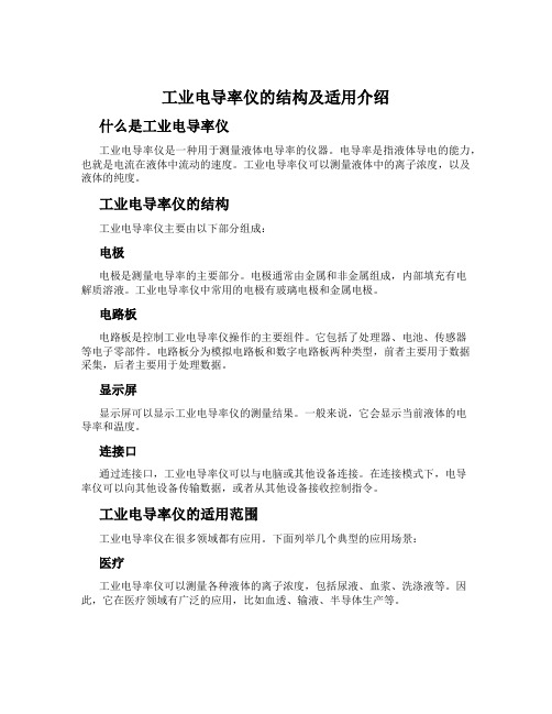
工业电导率仪的结构及适用介绍什么是工业电导率仪工业电导率仪是一种用于测量液体电导率的仪器。
电导率是指液体导电的能力,也就是电流在液体中流动的速度。
工业电导率仪可以测量液体中的离子浓度,以及液体的纯度。
工业电导率仪的结构工业电导率仪主要由以下部分组成:电极电极是测量电导率的主要部分。
电极通常由金属和非金属组成,内部填充有电解质溶液。
工业电导率仪中常用的电极有玻璃电极和金属电极。
电路板电路板是控制工业电导率仪操作的主要组件。
它包括了处理器、电池、传感器等电子零部件。
电路板分为模拟电路板和数字电路板两种类型,前者主要用于数据采集,后者主要用于处理数据。
显示屏显示屏可以显示工业电导率仪的测量结果。
一般来说,它会显示当前液体的电导率和温度。
连接口通过连接口,工业电导率仪可以与电脑或其他设备连接。
在连接模式下,电导率仪可以向其他设备传输数据,或者从其他设备接收控制指令。
工业电导率仪的适用范围工业电导率仪在很多领域都有应用。
下面列举几个典型的应用场景:医疗工业电导率仪可以测量各种液体的离子浓度,包括尿液、血浆、洗涤液等。
因此,它在医疗领域有广泛的应用,比如血透、输液、半导体生产等。
食品与饮料工业电导率仪可以检测食品和饮料中的离子浓度,以确保它们符合相关的食品安全标准。
此外,工业电导率仪还可以检测饮料中的糖分浓度。
化学工业工业电导率仪可以用于监测各种液体的离子浓度,如电镀液、清洗液、废水等。
通过监测这些液体的电导率,可以保证化学生产的质量和效益。
矿业工业电导率仪可以用于检测矿泉水的电导率,以确定水中的溶解物浓度。
此外,工业电导率仪还可以用于检测金属矿石中的金属含量。
结论工业电导率仪是一种用于测量液体电导率的仪器。
它由电极、电路板、显示屏和连接口等组件构成。
工业电导率仪可以在医疗、食品与饮料、化学工业和矿业等领域广泛应用。
电导率仪的原理及其使用介绍

电导率仪的原理及其使用介绍电导率仪主要是测液体介质之间传递电流能力的仪器,一般用于电力、化工、冶金、环保、制药、野外、湖泊、科研、食品和自来水等溶液中电导率值(TDS)的连续监测,同时在水处理,水产养殖试验方面也有应用。
电导率仪的工作原理:电导率是物体传导电流的能力,电导率测量仪的测量原理是将两块平行的极板;放到被测溶液中,在极板的两端加上一定的电势(通常为正弦波电压),然后测量极板间流过的电流。
根据欧姆定律,电导率(G)--电阻(R)的倒数,由导体本身决定的。
电导率的基本单位是西门子(S)。
因为电导池的几何形状影响电导率值,标准的测量中用单位电导率S/m(常用的还有μS/cm)来表示,以补偿各种电极尺寸造成的差别。
单位电导率(C)简单的说是所测电导率(G)与电导池常数(L/A)的乘积.这里的L为两块极板之间的液柱长度,A为极板的面积。
水的电导率与其所含无机酸、碱、盐的量有一定关系。
当它们的浓度较低时,电导率随浓度的增大而增加,因此,该指标常用于推测水中离子的总浓度或含盐量。
电导率仪使用时的注意事项:1、在测量纯水或超纯水时,为了避免测量值的漂移现象,建议采用密封槽;在密封状态下的进行流动测量,如采用烧杯取样测量,则会产生较大的误差。
2、因温度补偿是采用固定的温度系数,所以,超、高纯水的测量,尽量采用温度不补偿方式进行,测量后查表。
3、电极插头座应防止受潮,仪表应安置于干燥环境,避免因为水滴溅射或受潮,引起仪表的漏电或测量误差。
4、测量电极是精密部件,不可以分解,不可以改变电极形状和尺寸,且不可以用强酸、碱清洗,以免改变电极常数,而影响仪表测量的准确性。
5、为确保测量的精度,电极使用前,应用蒸馏水(或去离子水)冲洗二次(铂黑电极干放一段时间后,在使用前,必须在蒸馏水中浸泡),然后用被测试样水冲洗三次后,方可测量。
标签:电导率仪。
校准电导率仪的原理及应用介绍

校准电导率仪的原理及应用介绍概述电导率是溶液中离子导电性的量度,它是导体内的电流密度和电场强度之比,单位为西门子/米。
测量电导率常用的设备为电导率仪,校准电导率仪便是对它进行确认准确性的过程。
原理电导率仪主要由两个电极组成,一个电极作为传感器,另一个电极作为参考电极,两个电极之间放置样品。
传感器电极将电流施加到样品中,参考电极在通过样品之前和之后测量电势,然后比较电势之间的差异以计算电导率。
校准电导率仪是在对照样品的标准电导率下进行校准,校准时,通常会使用具有已知溶液浓度的标准参考物,比如KCl溶液,该参考溶液有确定的电导率值(在25°C下约为1413 µS/cm)。
与标准参考物进行比较,以确保电导率测量的准确性并进行必要的校正。
应用电导率仪是化学、生物及环境中广泛使用的仪器,应用领域包括加工内部化学物流、水力压裂水分回收、环境监测、食品加工和医学实验室等。
在各个应用领域中,准确的电导率测量是实现精确化学和生物实验,关键的环境监测和质量控制的必要条件。
在食品和饮料加工领域,电导率测量是控制流程、验证成分和纪步骤中的关键项。
在医疗实验室中,电导率测量被广泛使用,例如在药物开发、输液治疗和检测DNA实验。
在环境监测中,电导率是测定水体和土壤质量的指标之一,它对研究污染源现象、监测海水入侵或者其他水文地质问题都有十分重要的意义。
结论电导率仪是一种重要的化学和生物实验仪器,在许多领域中被广泛使用和应用。
进行校准是保证电导率仪测量准确性的重要步骤,以确保有效、精确的测量结果。
尽管电导率测量具有广泛的应用范围,但还需要更多的研究来提高其准确性和灵敏性,以更好的满足复杂的需求和挑战。
电导率仪及使用方法
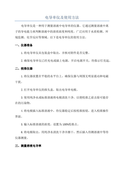
电导率仪及使用方法电导率仪是一种用于测量溶液中电导率的仪器。
它通过测量溶液中离子的导电能力来判断溶液中的溶质浓度和纯度,广泛应用于水质检测、环境监测、化学反应等领域。
以下是电导率仪的使用方法。
一、仪器准备1.将电导率仪从包装盒中取出,并核对附件是否完整。
2.确保电导率仪已经充电或插上电源,开启电源开关,待指示灯亮起。
二、校准仪器1.将仪器放置在平稳的水平台上,确保仪器与周围无明显震动和电磁干扰。
2.打开电导率仪的探头盖,取出电导率电极。
3.使用纯净水或标准溶液将电极清洗干净,以便校准之前去除可能存在的污染物。
4.将电极插入标准溶液中,待仪器稳定后按校准按钮,进入校准操作界面。
5.输入标准溶液的浓度,设置为100%校准点。
6.将电极取出,用纯净水清洗干净并擦干,然后插入待测溶液中等待仪器测量。
三、测量溶液电导率1.液面读数:将仪器探头完全插入待测液体中,待仪器稳定后,读取液面读数。
2.自动温度补偿:如果需要自动温度补偿,可以将温度传感器插入待测液体,仪器会自动根据温度修正电导率值。
3.记录测量结果:将测得的电导率值记录下来,可以进行进一步的数据分析和比较。
四、清洁与保养1.使用完毕后,需要用纯净水将电极及时清洗,并用纸巾擦干。
2.长时间不使用时,可以将电极存放在盖子内,避免灰尘和污染物附着损坏。
3.定期检查电导率仪的电极是否磨损或变形,如有问题及时更换。
五、注意事项1.仪器运行时应避免剧烈震动和大气湿度过高的环境。
2.避免将仪器暴露在阳光下,以免损坏仪器内部的元器件。
3.使用过程中避免仪器探头碰撞或撞击到硬物,以免影响测量结果。
4.尽量选择密闭的容器进行测量,避免溶液的流失影响测量准确性。
5.注意保护好电导率仪的电源线,避免电源线被拉扯或者弯曲过度造成损坏。
6.如果需要连续测量多个样品,可以在测量前充分冲洗电极,避免不同样品之间的污染。
总结:电导率仪是一种简单易用的测量仪器,通过校准并按照正确的使用方法操作,我们可以准确测量溶液中的电导率。
大地电导率仪
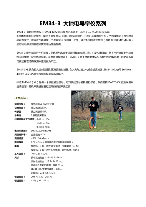
EM34-3 大地电导率仪系列E M34-3 大地电导率仪在EM31-MK2感应技术的基础上,采用了10 m,20 m与40m3种线圈间距布设模式,实现了最高达60米的不同探测深度。
三种可选线圈距外加2个偶极模式(水平模式与垂直模式)使得该仪器可在一个点实现6次测量。
此外,通过配加合适的软件(例如IX1D,EMIGMA等)还可利用多次测量结果实现地质剖面建模。
EM34-3操作简单且性价比高,是地质与水文类探测领域的专用工具。
广泛应用领域:地下水污染勘测与轮廓绘制以及地下饮用水源探测。
在垂直偶极模式下,EM34-3对于垂直地质结构有着独特的敏感度,因此在断裂与断层基岩结构探测中应用极为广泛。
EM34-3XL具有较大发射线圈和更高的发射能量。
在人为与/或大气噪音极高地区,EM34-3XL使用10/40m,4/10m以及4/20m线圈距均可提高信噪比。
标准EM34-3(XL)提供一个模拟输出信号;可对模数信号转换进行修正,从而支持DAS70-CX数据采集系统或任何计算机采集设备进行正常的数据采集工作。
测量指标:视电阻率以mS/m计量初始场源:独立偶极发射机传感器:独立偶极接收机参考线:2根轻质屏蔽线线圈间距与工作频率:6.4 kHz, 10m1.6 kHz, 20m0.4kHz, 40m电导率范围:10,100,1000 mS/m测量分辨率:全量程的0.1%测量精度:±5%(20mS/m)噪音等级:0.02 mS/m(高能量线干扰地区等级略高)电源:发射机:8节一次性D型电池;充电电池(可选)接收机:8节一次性C型电池;充电电池(可选)、工作温度:-40°C至+50°C尺寸:接收机控制台:19×13.5×26㎝发射机控制台:15.5×8×26㎝、接收机&发射机线圈:直径63㎝EM34-3XL发射机线圈:100㎝运输箱:27.5×75×75㎝仪器重量:20.5㎏;XL:26.5㎏装运重量:43㎏;XL:51㎏。
基于我国第七次北极科学考察—2016年夏季北极海冰厚度观测与特征分析
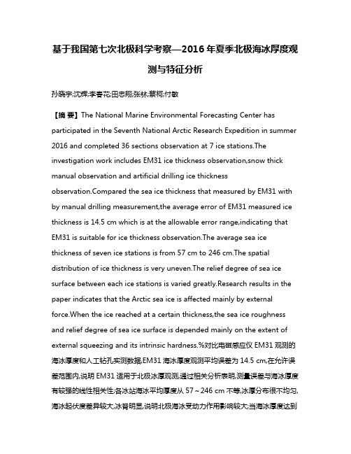
基于我国第七次北极科学考察—2016年夏季北极海冰厚度观测与特征分析孙晓宇;沈辉;李春花;田忠翔;张林;蔡柯;付敏【摘要】The National Marine Environmental Forecasting Center has participated in the Seventh National Arctic Research Expedition in summer 2016 and completed 36 sections observation at 7 ice stations.The investigation work includes EM31 ice thickness observation,snow thick manual observation and artificial drilling ice thicknesspared the sea ice thickness that measured by EM31 with by manual drilling measurement,the average error of EM31 measured ice thickness is 14.5 cm which is at the allowable error range,indicating that EM31 is suitable for ice thickness observation.The average sea ice thickness of seven ice stations is from 57 cm to 246 cm.The spatial distribution of ice thickness is very uneven.The relief degree of sea ice surface between each ice stations is varied greatly.Research results in the paper indicates that the Arctic sea ice is affected mainly by external force.When the ice reached at a certain thickness,the sea ice roughness and relief degree of sea ice surface is depended mainly on the extent of external squeezing and its intrinsic hardness.%对比电磁感应仪EM31观测的海冰厚度和人工钻孔实测数据,EM31海冰厚度观测平均误差为14.5 cm,在允许误差范围内,说明EM31适用于北极冰厚观测,通过相关分析表明,测量误差与海冰厚度有较强的线性相关性;各冰站海冰平均厚度从57~246 cm不等,冰厚分布很不均匀,海冰起伏度差异较大,冰脊明显,说明北极海冰受动力作用影响较大;当海冰厚度达到一定程度之后,海冰粗糙度和起伏度大小主要取决于海冰相互挤压程度和海冰本身硬度.【期刊名称】《海洋预报》【年(卷),期】2017(034)004【总页数】9页(P11-19)【关键词】北极;科学考察;海冰【作者】孙晓宇;沈辉;李春花;田忠翔;张林;蔡柯;付敏【作者单位】国家海洋环境预报中心,北京100081;国家海洋环境预报中心,北京100081;国家海洋环境预报中心,北京100081;国家海洋局海洋灾害预报技术研究重点实验,北京100081;国家海洋环境预报中心,北京100081;国家海洋环境预报中心,北京100081;国家海洋环境预报中心,北京100081;国家海洋环境预报中心,北京100081【正文语种】中文【中图分类】P731.15全球气候变暖的大背景下,北极海冰面积退缩显著[1-4],2016年夏季北极海冰最小范围为有卫星遥感记录以来第二低值,人们愈来愈关注该区域的变化。
EM34-3型大地电导率仪在大坝渗漏检测中的应用
第3 3卷 第 3期
20 0 6年 9月
黑
龙
江
水
专 学
报
Vo . 3, 13 No. 3
J un l f el gi gH da l n ier gC l g o ra o i n jn y rui E gnei ol e H o a c n e
s r n t e ig c n t u t n te g h n n o s r c i o
Ke r s d m a a ed tc in ywo d : a l k g ee t ;EM 3 — p at n u tvt eet r e o 4—3 Ty e rh c d cii d t o ;Xiu n a s ror e o y c q a y n Ree i v
S p. 2 0 e ,0 6
文章 编 号 :0 0—9 3 [0 6 0 —0 4 ~0 10 8 3 2 0 )3 0 3 3
E 4—3型 大 地 电导率 仪 在 M3 大 坝 渗漏 检测 中 的应 用
潘 多助 , 冬梅 徐
( 西泉眼水库管理 处, 黑龙江 阿城 4 3 M3 — 型大地电导率仪的工作 原理 , 对西 泉眼水 库大坝渗漏检测结果进行了分析 , 为大坝 除险加 固工程 设计 提
供依据 。
关键词 : 大坝渗漏检测 ;MM 一 型大地 电导率仪 ; E 3 西泉眼水库
中田分类号 : 9 TV68 文献标 识码 : A
( iun a sro ngmet e at n Xqa ynReev iMaae n pr r D met,A hn 5 3 0 el gi gPo .C i ) ceg 10 0 ,H in in rv ,hn o a a
电导率仪的种类和用途 电导率仪如何做好保养

电导率仪的种类和用途电导率仪如何做好保养电导率仪从使用用途分大致有笔形、便携式、试验室、工业用四种类型。
笔形电导率仪,一般制成单一量程,测量范围狭,为专用简便仪器。
笔形还有制成TDS计,用于测量饮用水质量,盐度计测量汤(溶液)盐度等电导率仪从使用用途分大致有笔形、便携式、试验室、工业用四种类型。
笔形电导率仪,一般制成单一量程,测量范围狭,为专用简便仪器。
笔形还有制成TDS计,用于测量饮用水质量,盐度计测量汤(溶液)盐度等。
便携式和试验室电导率测量范围较广,常用仪器,不同点是便推腊黄接受直流供电,可携带到现场。
试验室电导率仪测量范围广,功能多、测量精度高。
工业用电导率仪的特点是要求稳定性好、工作牢靠,有确定的测量精度、环境适应本领强、抗干扰本领强,具有模拟里量输出、数字通讯、上下限报警和掌控功能等。
—专业分析仪器服务平台,试验室仪器设备交易网,仪器行业专业网络宣扬媒体。
相关热词:等离子清洗机,反应釜,旋转蒸发仪,高精度温湿度计,露点仪,高效液相色谱仪价格,霉菌试验箱,跌落试验台,离子色谱仪价格,噪声计,高压灭菌器,集菌仪,接地电阻测试仪型号,柱温箱,旋涡混合仪,电热套,场强仪万能材料试验机价格,洗瓶机,匀浆机,耐候试验箱,熔融指数仪,透射电子显微镜。
使用完电导率仪后,用净水润洗,并避开接触有机溶剂,摔落或猛烈震荡都可能导致仪器失灵或损坏。
A、操纵温度:溶液温度超过1600F/71℃时,不能进行丈量,否则要损坏仪器。
当环境温度低于0℃时,pH电极可能会损坏,千万留意,不要超出规定温度范围。
把仪器存放在热源四周或在天气酷热的情况下,温度很轻易达到或超过1500F,这将导致仪器丈量不准。
B、电池的更换:擦干仪器表面,拧开后面四颗螺丝,当心打开后盖,移走后盖,把电池取下,并换上新的9V碱性电池,盖上后盖,拧紧螺丝。
注:由于已安装了不可擦除可读存储器,即使电源断电或更换电池的过程中,存储在记忆器中的记录数据和校正更改设置并不会消失。
电导率仪用途作用
电导率仪用途作用电导率仪是一种用于测定溶液电导率的仪器,它主要通过测量电解质溶液的电导率来评估其溶解度和离子浓度的工具。
电导率是导电体材料的一种物理性质,它反映了溶液中离子的浓度和移动能力,因此电导率仪可以广泛应用于化学、生物、环境等领域,具有重要的作用和价值。
首先,电导率仪在化学领域中具有重要的应用价值。
在化学实验中,通过测量溶液的电导率可以间接地推测出其中的离子浓度,从而评估其溶解度。
这对于一些化学实验来说是非常重要的,比如在溶解度试验中,可以通过电导率仪来监测溶质在特定温度下的溶解度。
此外,电导率仪还可以用于溶液中离子浓度的快速测定,对于化学物质的质量控制和品质鉴定也具有很大的帮助。
其次,电导率仪在生物领域中也有着重要的应用。
在生物实验中,电导率仪可以用于监测细胞培养液中离子浓度的变化,从而评估细胞的健康状况。
此外,电导率仪还可以用于测定生物体内外的离子浓度,对于生物体内环境的平衡和调节具有重要的意义。
另外,电导率仪在环境领域中也发挥着重要的作用。
在环境监测和保护中,电导率仪可以用于检测水体中的离子浓度,评估水质的好坏。
它可以帮助监测水体中的污染物浓度,提前预警环境问题,从而保护生态环境。
此外,电导率仪还被广泛应用于食品工业、医药工业等领域。
在食品工业中,电导率仪可以用于检测食品中的盐分和糖分等成分,对于食品品质的评估具有重要的作用。
在医药工业中,电导率仪可以用于制药过程中对药物的纯度和质量的快速检测。
除此之外,电导率仪还可以用于水处理和污水处理等工程实践中。
在水处理过程中,可以通过电导率仪对水中的盐度和溶解物质进行监测,帮助调节水质。
在污水处理过程中,电导率仪可以用于监测污水中的离子浓度和盐分浓度,判断污水的处理效果。
总之,电导率仪作为一种测量电导率的专用仪器,具有广泛的应用领域和重要的作用。
它不仅可以用于化学实验、生物实验和环境监测等科研领域,还可以应用于工业生产、食品安全、医药工业等实际生产领域。
EM31大地电导率仪-技术说明5

We wish to emphasize three important points. If (i) the value of R1 (the electrical resistance of loop 1 is large; if (ii) the transmitter frequency is very small; and finally if (iii) we focus our attention only on those current loops that flow in the immediate vicinity of the transmitter loop, then simple circuit theory (described in Technical Note TN-6) shows that we can ignore the loop impedances caused by the self inductance L1 and the mutual inductance M (which arises from magnetic coupling with other current loops generated by the primary magnetic field). In this case the ground current i1 that flows in loop 1 is given (through Ohm’s law) by i1 = eP / R1 . This ground current will be “in-phase” with eP and thus in “quadrature” phase with the primary transmitter current and the primary magnetic field. Of course this ground current i1 will (like the primary current in the transmitter coil), generate a proportional (secondary) magnetic field which we can measure, along with the primary magnetic field arising directly from the transmitter current, using a receiver coil located on the surface of the earth at a distance s from the transmitter coil. The major differences between the primary and the total secondary magnetic fields will be that the primary field caused by the large transmitter current will be much larger than
电导率仪的使用方法

电导率仪的使用方法电导率仪是一种用于测量水溶液中电导率的仪器,它通常用于监测水质、环境保护和实验室研究等领域。
正确的使用方法对于获得准确的测量结果至关重要。
本文将介绍电导率仪的正确使用方法,以帮助用户更好地操作和维护这一仪器。
1. 准备工作。
在使用电导率仪之前,首先要进行准备工作。
确保电导率仪处于干燥、通风的环境中,远离强磁场和电磁干扰。
检查仪器表面是否干净,电极是否完好,电源是否正常,以及测量所需的标准溶液是否准备充分。
2. 校准电导率仪。
在进行实际测量之前,必须对电导率仪进行校准。
校准的目的是确保仪器能够准确地测量电导率。
首先,使用标准溶液对电导率仪进行零点校准,然后使用另一种标准溶液进行斜率校准。
校准完成后,确认仪器显示的数值与标准溶液的电导率值一致。
3. 进行测量。
在校准完成后,即可进行实际的电导率测量。
首先,将待测溶液倒入测量池中,确保液面平整。
然后,将电导率仪的电极插入溶液中,等待一段时间直至仪器稳定显示电导率数值。
在测量过程中,要确保电极与容器壁不发生接触,以免影响测量结果。
4. 清洁与维护。
在使用完电导率仪后,要及时对仪器进行清洁与维护。
首先,使用纯水清洗电极,然后用干净的软布擦干。
注意不要使用化学溶剂或强酸强碱清洗电极,以免损坏电极。
另外,定期对电导率仪进行全面的检查与维护,确保仪器的稳定性和准确性。
5. 存放与保养。
在使用电导率仪之后,要将其存放在干燥、通风的环境中,远离阳光直射和潮湿。
定期对仪器进行保养,包括检查电极的状态、更换老化的电极和维护仪器的外壳。
正确的存放和保养可以延长电导率仪的使用寿命,并确保测量结果的准确性。
总结。
电导率仪是一种重要的水质分析仪器,正确的使用方法对于获得准确的测量结果至关重要。
在操作电导率仪时,要注意准备工作、校准、测量、清洁与维护、存放与保养等方面,确保仪器的稳定性和准确性。
只有在正确使用的前提下,电导率仪才能发挥其最大的作用,为水质监测和环境保护工作提供有力的支持。
欧华联 EM38-MK2-1 大地电导率仪使用说明书
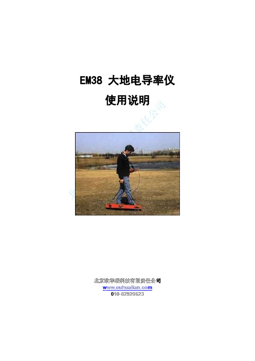
EM38大地电导率仪使用说明北京欧华联科技有限责任公司w ww w w.o u h u a l i a n.c o m010-********1仪器原理EM38的后端有一个小型发射线圈,它可以产生一个随时间变化的初级磁场,这个磁场在大地中诱导出微小电子涡流,而EM38的前端有一个小型接受线圈,这个接受器既接受发射线圈产生的磁场,又接受由初级磁场诱导出的次级磁场,通过测量诱导出的次级磁场来测量大地电导率。
一些技术问题请参见网址:/html/technicalnotes.html2仪器结构EM38-MK2能够同时测量大地电导率和磁化率,仪器带2个发射接受线圈,分别测量1米和0.5米的全相和两相参数值,输出可以用采集器记录的4组数据,前面有两个表,侧面有两个和前面一样功能的表,用来监测所测量的数据,取决于模式开关的设置。
EM38-MK2-1有一个发射接受线圈,测量并记录全相和同相两组数据,3仪器使用3.1简化方法以下是EM38-MK2使用前的准备工作,推荐的不同程序间的时间间隔是一般值,实验表明,条件不好时要多实施几次,条件好时可以适当减少次数,两个线圈操作一样,这里只介绍1米的。
3.1.1电池的检测在每次使用EM38前,建议检测电池电量,旋转主机上MODE旋钮至BAT,此时读取屏幕数值,该数值在1500~720时为正常电量,如果不在这个范围内,请更换电池,该仪器使用一节9V电池。
3.1.2仪器零点的校准把MODE旋钮调到“1米”(0.5米的线圈拨到0.5米的位置)位置,按一下步骤设置1.将仪器水平模式放置,设置Q/P和I/P读数为零2.调节Q/P旋钮为任意值(如H=10mS/m),然后调节仪器到竖直模式,记录读数(V=16mS/m),然后减去水平模式下的值(V-H=6mS/m)。
3.再次放到水平模式,调节Q/P为上面的差值,再放到竖直模式时,读书应该为12mS/m。
注:仪器在至少1.5米以上的高度时,Q/P读数或者电导率满足以下等式:V=2H用0.5米的分离线圈时选择0.5米的位置。
7.大地电导率仪的应用
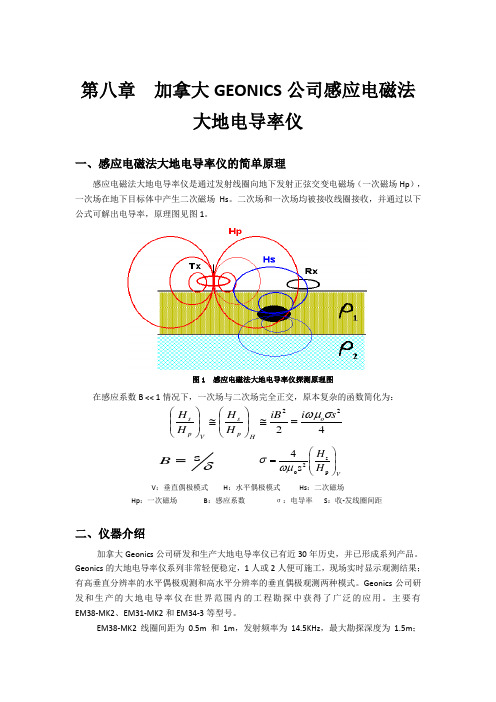
第八章 加拿大GEONICS 公司感应电磁法大地电导率仪一、感应电磁法大地电导率仪的简单原理感应电磁法大地电导率仪是通过发射线圈向地下发射正弦交变电磁场(一次磁场Hp ),一次场在地下目标体中产生二次磁场Hs 。
二次场和一次场均被接收线圈接收,并通过以下公式可解出电导率,原理图见图1。
在感应系数B << 1情况下,一次场与二次场完全正交,原本复杂的函数简化为:4222s i iB H H H H o H p s V p s σωμ=≅⎪⎪⎭⎫ ⎝⎛≅⎪⎪⎭⎫ ⎝⎛VH H ⎪⎪⎭⎫ ⎝⎛=p s 2o s 4ωμσ V :垂直偶极模式 H :水平偶极模式 Hs :二次磁场Hp :一次磁场 B :感应系数 σ:电导率 S :收-发线圈间距二、仪器介绍加拿大Geonics 公司研发和生产大地电导率仪已有近30年历史,并已形成系列产品。
Geonics 的大地电导率仪系列非常轻便稳定,1人或2人便可施工,现场实时显示观测结果;有高垂直分辨率的水平偶极观测和高水平分辨率的垂直偶极观测两种模式。
Geonics 公司研发和生产的大地电导率仪在世界范围内的工程勘探中获得了广泛的应用。
主要有EM38-MK2、EM31-MK2和EM34-3等型号。
EM38-MK2线圈间距为0.5m 和1m ,发射频率为14.5KHz ,最大勘探深度为1.5m ;图1 感应电磁法大地电导率仪探测原理图 δs=BEM31-MK2线圈间距为3.66m,发射频率为9800HZ,有效勘探深度能达到5.5m;EM34-3线圈间距为10m、20m、40m,分别对应于发射频率为6400HZ、1600HZ、400HZ,最大勘探深度能达到60m,其中EM34-3XL可在电磁干扰噪声很强的地方获得好的观测结果。
图2、图3、图4分别对应EM38-MK2、EM31-MK2和EM34-3感应电磁法大地电导率仪。
图2 EM38-MK2图3 EM31-MK2图4 EM34-3技术指标EM34-3•测量值:视电导率mS/m•一次场源:内置偶极发射器•传感器:内置偶极接收器•参考电缆:轻便双芯屏蔽电缆•接收—发射线圈距及工作频率:10m, 6.6KHz20m, 1.6KHz40m, 0.4KHz•电源:发射机:8块一次性或可充电“D”电池接收机:8块一次性或可充电“C“电池•电导率范围:10,100,1,000 ms/m•测量分辨率:满程的±0.1%•测量精度:20mS/m时±5%•噪声水平:0.2mS/m(存在高压线干扰的地区噪声增大)•尺寸:接收器控制箱:19×13.5×26cm发射器控制箱:155×8×26cm接收和发射线圈:直径63cm运输包装箱:27.5×75×75cm ﹡20.5kg(运输重量:43kg)EM31-MK2•测量指标:1:视电阻率以mS/m计量2:二次场至初次场的同相位率以ppt计量•线圈间距: 3.66m•工作频率:9.8 kHz•测量范围:电导率:10,100,1000mS/m;同相位:±20 ppt•测量分辨率:全量程的±0.1%•测量精度:±5%(20mS/m)•噪音等级:电阻率:0.1Ms/m; 同相位:0.03 ppt•数据存储:512M内置磁盘存储器;兼容PC卡•电源:8节一次性“C”型碱性电池(约可持续供电20小时)•工作温度:仪器:-40°C至+50°C数据记录器:-20°C至+60°C•尺寸:长杆:展开4.0m,折合1.4m装运箱:145×38×23㎝•重量:仪器:12.4㎏;装运重量:28㎏三、应用实例1. EM38-MK2圈定公墓为改建公墓需要,就得查明以往公墓的分布情况,避免改建纠纷。
EM38大地电导率探测仪
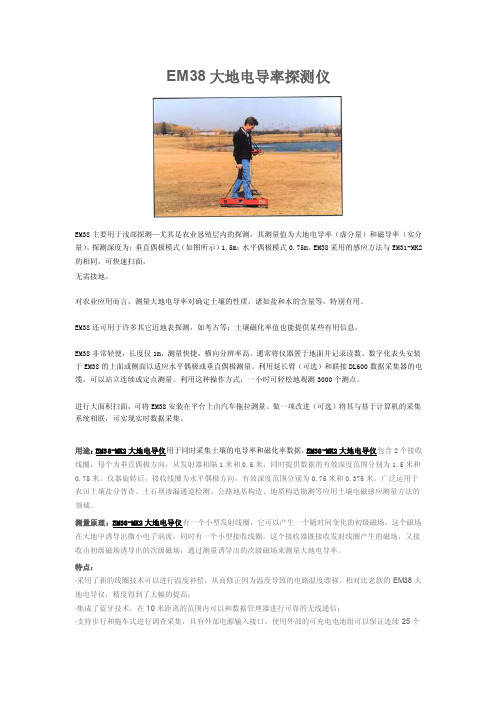
EM38大地电导率探测仪EM38主要用于浅部探测—尤其是农业恳殖层内的探测,其测量值为大地电导率(虚分量)和磁导率(实分量)。
探测深度为:垂直偶极模式(如图所示)1.5m;水平偶极模式0.75m。
EM38采用的感应方法与EM31-MK2的相同,可快速扫面,无需接地。
对农业应用而言,测量大地电导率对确定土壤的性质,诸如盐和水的含量等,特别有用。
EM38还可用于许多其它近地表探测,如考古等;土壤磁化率值也能提供某些有用信息。
EM38非常轻便,长度仅1m,测量快捷,横向分辨率高。
通常将仪器置于地面并记录读数。
数字化表头安装于EM38的上面或侧面以适应水平偶极或垂直偶极测量。
利用延长臂(可选)和联接DL600数据采集器的电缆,可以站立连续或定点测量。
利用这种操作方式,一小时可轻松地观测3000个测点。
进行大面积扫面,可将EM38安装在平台上由汽车拖拉测量。
做一项改进(可选)将其与基于计算机的采集系统相联,可实现实时数据采集。
用途:EM38-MK2大地电导仪用于同时采集土壤的电导率和磁化率数据,EM38-MK2大地电导仪包含2个接收线圈,每个为垂直偶极方向,从发射器相隔1米和0.5米,同时提供数据的有效深度范围分别为1.5米和0.75米。
仪器旋转后,接收线圈为水平偶极方向,有效深度范围分别为0.75米和0.375米。
广泛运用于农田土壤盐分普查、土石坝渗漏通道检测、公路地基构造、地质构造勘测等应用土壤电磁感应测量方法的领域。
测量原理:EM38-MK2大地电导仪有一个小型发射线圈,它可以产生一个随时间变化的初级磁场,这个磁场在大地中诱导出微小电子涡流,同时有一个小型接收线圈,这个接收器既接收发射线圈产生的磁场,又接收由初级磁场诱导出的次级磁场,通过测量诱导出的次级磁场来测量大地电导率。
特点:·采用了新的线圈技术可以进行温度补偿,从而修正因为温度导致的电路温度漂移,相对比老款的EM38大地电导仪,精度得到了大幅的提高;·集成了蓝牙技术,在10米距离的范围内可以和数据管理器进行可靠的无线通信;·支持步行和拖车式进行调查采集,具有外部电源输入接口,使用外部的可充电电池组可以保证连续25个小时工作;·可选校准部件实现自动仪器校准。
EM-38大地电导率仪
EM38-MK2大地电导率仪
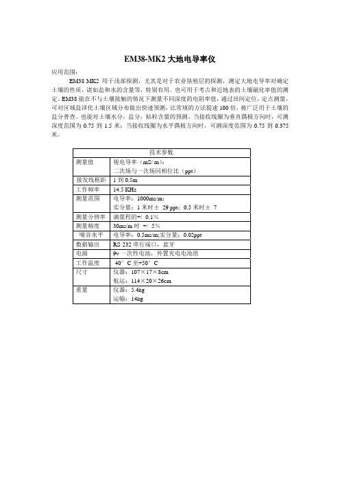
应用范围:
EM38-MK2用于浅部探测,尤其是对于农业垦殖层的探测,测定大地电导率对确定土壤的性质,诸如盐和水的含量等,特别有用。
也可用于考古和近地表的土壤磁化率值的测定。
EM38能在不与土壤接触的情况下测量不同深度的电阻率值,通过田间定位,定点测量,可对区域盐泽化土壤区域分布做出快速预测,比常规的方法提速100倍,被广泛用于土壤的盐分普查。
也能对土壤水分,盐分,粘粒含量的预测。
当接收线圈为垂直偶极方向时,可测深度范围为0.75到1.5米;当接收线圈为水平偶极方向时,可测深度范围为0.75到0.375米。
技术参数
测量值视电导率(mS/ m);
二次场与一次场同相位比(ppt)
接发线框距1到0.5m
KHz
工作频率 14.5
测量范围电导率:1000ms/m;
实分量:1米时± 29 ppt;0.5米时± 7
测量分辨率满量程的+/ -0.1%
测量精度 30ms/m时 +/ -5%
噪音水平电导率:0.5ms/m;实分量:0.02ppt
数据输出 RS-232串行端口,蓝牙
电源 9v一次性电池,外置充电电池组
工作温度 -40°C至+50°C
尺寸仪器:107×17×8cm
航运:114×20×26cm
重量仪器:5.4kg
运输:14kg。
电磁感应法大地电导率仪及金属探测仪在管道探测上可行性研究
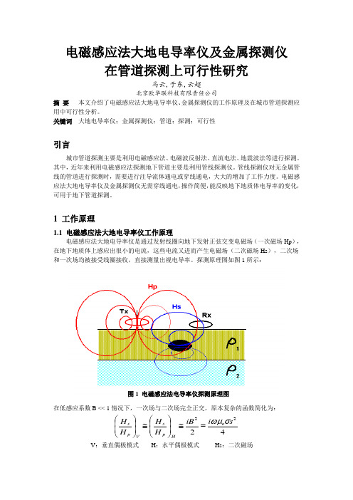
电磁感应法大地电导率仪及金属探测仪在管道探测上可行性研究马云,于东,云超北京欧华联科技有限责任公司摘 要 本文介绍了电磁感应法大地电导率仪、金属探测仪的工作原理及在城市管道探测应用中可行性分析。
关键词 大地电导率仪;金属探测仪;管道;探测;可行性引言城市管道探测主要是利用电磁感应法、电磁波反射法、直流电法、地震波法等进行探测。
其中,近年来利用电磁感应法探测地下管道主要是利用管线探测仪。
管线探测仪对无金属管线的管道进行探测时,需要进行注导流体通电或穿线通电,大大的增加了工作力度。
电磁感应法大地电导率仪及金属探测仪无需穿线通电,操作简便,能反映地下地质体电导率的变化,可用于地下管道探测。
1 工作原理1.1 电磁感应法大地电导率仪工作原理电磁感应法大地电导率仪是通过发射线圈向地下发射正弦交变电磁场(一次磁场Hp ),在地下地质体上感应出很小的电流,这些电流又进而产生电磁场(二次磁场Hs ),二次场和一次场均被接受线圈接收,直接测量出视电导率。
探测原理图如图1所示:在低感应系数B << 1情况下,一次场与二次场完全正交,原本复杂的函数简化为:4222s i iB H H H H o Hp s V ps σωμ=≅⎪⎪⎭⎫ ⎝⎛≅⎪⎪⎭⎫ ⎝⎛V :垂直偶极模式 H :水平偶极模式 Hs :二次磁场图1 电磁感应法电导率仪探测原理图Hp:一次磁场B:感应系数σ:电导率S:线圈间距1.2 金属探测仪工作原理金属探测仪是利用不接地发射线圈向地下发射一次脉冲磁场,在一次脉冲磁场间歇期间利用接收线圈观测地下介质中引起的二次感应涡流场,从而探测地下电阻率的变化。
探测原理如图2所示:2 应用实例及数据分析2.1 北京沙河北大桥某区地下管道探测2.1.1地质情况该区位于北京沙河北大桥一PVC管道上,管道埋深为3m,直径为1m,管道上方为松散的覆土填埋层。
沿着垂直于管道方向布设一条测线,采用EM31、EM34-3大地电导率仪对该剖面进行了探测。
涡流电导率仪的应用领域
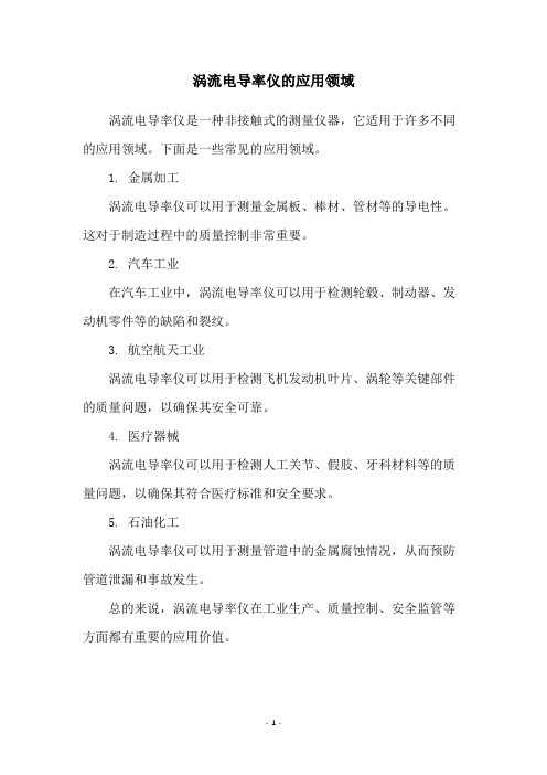
涡流电导率仪的应用领域
涡流电导率仪是一种非接触式的测量仪器,它适用于许多不同的应用领域。
下面是一些常见的应用领域。
1. 金属加工
涡流电导率仪可以用于测量金属板、棒材、管材等的导电性。
这对于制造过程中的质量控制非常重要。
2. 汽车工业
在汽车工业中,涡流电导率仪可以用于检测轮毂、制动器、发动机零件等的缺陷和裂纹。
3. 航空航天工业
涡流电导率仪可以用于检测飞机发动机叶片、涡轮等关键部件的质量问题,以确保其安全可靠。
4. 医疗器械
涡流电导率仪可以用于检测人工关节、假肢、牙科材料等的质量问题,以确保其符合医疗标准和安全要求。
5. 石油化工
涡流电导率仪可以用于测量管道中的金属腐蚀情况,从而预防管道泄漏和事故发生。
总的来说,涡流电导率仪在工业生产、质量控制、安全监管等方面都有重要的应用价值。
- 1 -。
工业电导率仪的原理及应用

工业电导率仪的原理及应用一、工业电导率仪的原理工业电导率仪是一种用于测量溶液中电导率的仪器。
电导率是指电流在单位电场强度下通过某个物体的能力,通常用于评估溶液中的离子浓度和溶液中物质的纯度。
工业电导率仪的原理基于电导率的定义,利用一对电极将电流通过液体或溶液中的离子,并测量通过液体的电流强度和电压差。
根据欧姆定律,电导率可以通过以下公式计算:电导率 = 电流强度 / 电场强度电导率仪中的电极是通过电极材料与液体或溶液中的离子发生反应,并产生电流。
电极通常由不锈钢、铂或碳材料制成。
液体或溶液中的离子通过与电极接触,并改变导电能力。
二、工业电导率仪的应用工业电导率仪主要应用于以下领域:1.水质监测:工业电导率仪是水质监测的重要工具。
它可以测量水中溶解物质的浓度,并评估水的纯度。
在饮用水和污水处理过程中,工业电导率仪可帮助监测水质的变化,以确保水的安全和纯净。
2.食品和饮料行业:工业电导率仪可以测量食品和饮料的含盐量和纯度。
在食品和饮料加工过程中,电导率仪可以用于监测盐度和浓度,确保产品质量符合标准。
3.医药和化工行业:工业电导率仪在医药和化工行业中具有重要作用。
它可以用于测量药品和化学物质的浓度,以确保产品的质量和稳定性。
此外,电导率仪还可以监测反应过程中溶液中离子的变化。
4.土壤和农业应用:工业电导率仪可以用于测量土壤中的盐分含量和肥料浓度。
这对于农业和植物研究非常重要,可以帮助农民和研究人员确定适合植物生长的土壤条件。
5.化学实验室:工业电导率仪常用于化学实验室中。
它可以用于测量溶液中的离子浓度,评估化学试剂的纯度以及监测反应过程中的变化。
总之,工业电导率仪具有广泛的应用领域,可以用于监测水质、食品、药品和化学物质的浓度和纯度。
它在工业生产和科研中起着十分重要的作用,并有助于保证产品质量和实验结果的准确性。
- 1、下载文档前请自行甄别文档内容的完整性,平台不提供额外的编辑、内容补充、找答案等附加服务。
- 2、"仅部分预览"的文档,不可在线预览部分如存在完整性等问题,可反馈申请退款(可完整预览的文档不适用该条件!)。
- 3、如文档侵犯您的权益,请联系客服反馈,我们会尽快为您处理(人工客服工作时间:9:00-18:30)。
METHODS USED TO CARRY OUT SIX ROADWAY INVESTIGATIONS OF SINKHOLESRichard C. BensonTechnos, Inc.3333 NW 21st Street, Miami FL 33142info@ABSTRACTKarst conditions are a prevalent problem impacting many roads, bridges and highways of the United States. Six case-histories present an overview of investigations made to determine the presence of karst (sinkholes and cavities) and their possible impact on existing or new construction. These six case-histories represent projects which range from reconnaissance investigations to identify possible areas of karst, to detailed investigations including follow-up drilling and remediation considerations. They also cover a wide range of scale (dimensions) of roadway problems.Each of the six investigations utilized a wide range of data including aerial photos, surface geophysical measurements (on water as well as on land), drilling and geophysical logging. The selection of the methods for each of the unique site conditions is presented, including t h e parameters measured, the depth of measurements, the site coverage and how the data provide information on subsurface conditions.In each investigation, the non-intrusive geophysical data provide an assessment of the subsurface conditions that, when integrated with other data, allow the pieces of the puzzle to be brought together in an accurate conceptual model of subsurface karst conditions. The results of this integrated information provided the highway design engineers with the necessary data for d eveloping design and remediation strategies.PART IA BRIEF SUMMARY OF SIX ROADWAY INVESTIGATIONS IN KARSTIntroductionThis paper contains two parts. Part I provides an overview of the geophysical measurements made as part of the six roadway investigations in karst. Part II provides an expanded discussion of two of the six case-histories using these strategies.The six case-histories include:• A detailed emergency investigation of localized subsidence over 1,000 feet on U.S. 27 for Florida DOT;• A reconnaissance investigation of localized subsidence over 1600 feet of Interstate 24 median for Tennessee DOT;• A reconnaissance investigation of karst conditions over 4.2 miles of Route 340 for Virginia DOT prior to final design of roadway expansion;• A reconnaissance and detailed investigation to define areas of karst susceptibly over 7,000 feet of I-70 for Maryland DOT to plan long-term maintenance (Benson, et al, 1998a, 1998b);• A reconnaissance and detailed investigation of a localized area of about one acre for Federal Bureau of Prisons prior to design (Daniel et al., 1999); and• A reconnaissance investigation for Florida DOT with follow-up detailed investigation along 8,000 feet of U.S. 1 for a new bridge over water (Benson, et al., 1995a, 1195b).While a ll six of the sites are in karst environments: three are associated with present sinkhole activity, two are in areas with historic karst but no recent activity, and one is in an area of no known karst activity. Details of three of the investigations including the geologic setting, the strategy used and the results, are provided in the referenced papers.Table I summarizes the nature and scale of each project. The size of the sites range from a few acres to 4.2 miles of roadway. Tables II through VII summarize the non-intrusive geophysical methods used on each project and their purpose. Table VIII summarizes the results of the investigations.Table I – Summary of six karst investigationsSite Client Reconnaissance Detail Area/Length ConditionU.S. 27 Florida DOT X 1,000 feet Sinkhole activityI-24 Tennessee DOT X 1,600 feet Sinkhole activity Route 340 Virginia DOT X 4.2 miles Historic karstpresentI-70 Maryland DOT X X 7,000 feet Sinkhole activityVirginia Prison Federal Bureauof Prison X X few acres Historic karstactivityU.S. 1 Florida DOT X X 8,000 feet Unknown karstactivityU.S. 27 (Florida DOT)Technos responded to an emergency call from the Florida Department of Transportation to provide an assessment of sinkhole collapse on US Highway 27 in Sebring, Florida. An estimated 200 cubic yards of material had been lost, resulting in about 2 feet of subsidence over a portion of the northbound lanes. Subsidence was centered around a surface water drainage system. During the week prior to subsidence, repairs had been made to an area about 500 feet to the south. There are two possible causes of subsidence at this location: one is due to flushing of sand into a surface water drainage structure; another is due to a deep seated cause of collapse associated with karst conditions within rock at a depth of more than 250 feet.Table II lists the geophysical measurements made at this site and Figure 1 shows their depth of investigation.Table II – A detailed investigation of 1,000 feet, Florida DOTMethod Measured Parameter Station Spacing ProvidesEM31 Electrical conductivity to adepth of 20 feet Continuous Identification of variationsin shallow strataMicrogravity Density to a depth ofmore than a few 100 feet 20 to 40 foot Identification of zones oflow density due tosubsidence exist atdepthResistivity Electrical resistivity to adepth of 100 feet 20-foot electrode spacing Detailed characterizationof lateral and verticalchanges inunconsolidated materialGround penetrating radar Dielectric constant to adepth of 10 to 15 feet Continuous Shallow indications ofsoil pipingI-24 (Tennessee DOT)A section of Interstate 24 south of Nashville had recently underwent construction. After construction, a section of the median experienced localized sinkholes with subsidence cracks extending out to the edge of the shoulders within the median. The Tennessee Department of Transportation contracted with Technos, Inc. to conduct a karst investigation of the site. This investigation identified areas of deeper weathered rock associated with regional lineaments. These areas had become active due to diversion and concentration of surface water runoff. Technos responded to a request from TN-DOT to identify the cause of the problem.Table III lists the geophysical measurements made at this site and Figure 2 shows their depth of investigation.Table III – A reconnaissance investigation for Tennessee DOTMethodMeasured Parameter Station SpacingProvides2D ResistivityResistivity to a depth of 80 feet20-foot electrode spacingMap of top of rock, Identification of highly weathered zonesGround Penetrating Radar Dielectric constant, to a depth less than 10 feetContinuous Shallow indications of soil pipingEM31Electrical conductivity to adepth of 20 feetContinuous Identification of variations in soil conditions and top of rockRoute 340 (Virginia DOT)Route 340 is a two lane road that runs along the eastern side of the South Fork of the Shenandoah River in northwestern Virginia. Four bridge replacements and associated road improvements are planned over 4.2 miles. Numerous sinkholes and caves are present along the route. A reconnaissance investigation was carried out to characterize the geology and thickness of soil cover (cutter and pinnacles), and to identify possible karst conditions (highly weathered and fractured rock, sinkholes and cavities). These data were used to design a detailed drilling program.Table IV lists the geophysical measurements made at this site and Figure 3 shows their depth of investigation.Table IV – A reconnaissance investigation of 4.2 miles, Virginia DOTMethod Measured Parameter Station Spacing ProvidesEM31 Electrical conductivity to adepth of 20 feet Continuous Identification of variationsin depth of rock andweathered zonesEM34 Electrical conductivity to adepth of 50 feet Continuous Identification of variationsin depth of rock andweathered zones2D Resistivity Imaging Electrical resistivity to adepth of 100 feet 20-foot electrode spacing Detailed characterizationof fractured andweathered zones in rockI-70 (Maryland DOT)A significant number of sinkholes had opened up along I-70 a nd nearby roadways south of the city of Frederick, Maryland. Extensive emergency grouting was undertaken at certain locations along I-70 in an effort to remediate the problem. A karst investigation was carried out to assess subsurface conditions along 7,000 feet of highway to locate areas in which potential collapse may be concentrated. The results clearly identified two zones which were highly prone to sinkholes development (Benson, et al, 1998-1999).Table V lists the geophysical measurements made at this site and Figure 4 shows their depth of investigation.Table V - Maryland DOTMethod Measured Parameter Station Spacing ProvidesEM31 Electrical conductivity to adepth of 20 feet Continuous Identification of variationsin depth of rockEM34 Electrical conductivity to adepth of 50 feet Continuous Identification of variationsin depth of rockMicrogravity Density to a depth ofmore than 600 feet 15-foot Identification of zones oflow density due todissolution of limestone(cavities andsubsidence)Virginia Prison (Federal Bureau of Prison)A major federal prison facility was to be constructed in an area of southwestern Virginia, which is a known area of extensive karst development. The main access road to the site along with main utilities for the site cross a “saddle” area between two major coalescing sinkholes. An investigation of subsurface conditions was carried out to evaluate subsurface conditions and to obtain data for site stabilization and construction (Daniel, et al., 1999).Table VI lists the geophysical measurements made at this site and Figure 5 shows their depth of investigation.Table VI – Virginia PrisonMethod Parameter Measured Station Spacing ProvidesEM31 Electrical conductivity to adepth of 20 feet Continuous Identification of variationsin depth of rock andweathered zonesMicrogravity Density to a depth ofmore than 100 feet 25- foot Identification of lowdensity zones due todeeper rock andpossible karst zonesU.S. 1 (Florida DOT)A high four-lane bridge was planned to replace an existing two-lane draw bridge over Jewfish Creek and Lake Surprise, just north of Key Largo, Florida. Lake Surprise is a shallow circular lake with U.S. 1 passing though its center for about 3,500 feet. Drilled shaft foundations for the bridge will be placed parallel to U.S. 1 over Jewfish Creek and through the center of Lake Surprise. There were a few subtle indications of potential karst in the area. An investigation was carried out to determine if karst conditions existed along the proposed route. The results identified a zone of paleokarst about 1800 feet long where piles for the high portion of the bridge would be placed. These data provided the basis for a cost effective safe design (Benson, et al, 1995a and 1995b).Table VII lists the geophysical measurements made at this site and Figure 6 shows their depth of investigation.Table VII - Florida DOTMethod Measured Parameter Station Spacing ProvidesSubbottom Profiling (Seismic Reflection) Acoustic Impedance(velocity and density) to adepth of 200 feetContinuous 2D stratigraphic cross-sections identify dippingstrataMicrogravity Density to a depth ofmore than 1,000 feet 25 foot Identification of lowdensity zones (possiblepaleokarst zones)Deep Subbottom Profiling (Seismic Reflection) Acoustic Impedance(velocity and density) to adepth of 1,000 feetContinuous 2D stratigraphic cross-sections identify dippingstrataGeophysical Logging Natural gamma, densityand porosity over lengthof the borehole Continuous Details of strata,presence of voids andlow density zonesTable VIII summarizes the results of each investigation. In each case, the zone of karst conditions were identified and characterized.Table VIII – Summary Results of Each InvestigationSite Conditions Results U.S. 27 (Florida DOT) Sinkhole activity Results suggest the cause wasdue to shallow soil piping into asurface water drainage system I-24(Tennessee DOT) Sinkhole activity Results identified weatheredzones in rock which weresusceptible to subsidence Route 340 (Virginia DOT) Historic karst present Results identified zones ofconcernI-70 (Maryland DOT) Sinkhole activity Results characterized karstconditions and identified zone ofmajor dissolution of bedrockwhich were susceptible tosubsidenceVirginia Prison (Federal Bureau of Prisons) Historic karst activity Results identified a cavitysystem under the proposedroadwayU.S. 1 (Florida DOT) Unknown karst activity Results identified zone of paleo-collapse which would impactbridge foundations In five cases, some measurements were 20 feet deep or less. In many cases, these reconnaissance measurements were not deep e nough to detect the origin of the subsidence problem. However, most subsidence activity is associated with changes in the shallow near surface conditions, which are often readily detected (see papers by Benson and LaFountain (1984) and Benson and Yuhr (1987) which discus near-surface indicators).Note that EM measurements are commonly used because they are continuous, rapid and easily applied to many situations where data in the upper 20 to 50 feet may be important. Note that 2D resistivity imaging and m icrogravity are commonly used to obtain deeper data. These deeper measurements are limited in resolution in part by station spacing and are inherently slower than continuous measurements such as EM.PART IIA REVIEW OF GEOPHYSICAL METHODS USED ON TWO OF THE SIX CASE-HISTORIESFive key issues will impact the success of karst investigations. They include:• An assessment of measurable parameters so that measurement methods can be selected that have a reasonable chance of yielding appropriate results within the given geologic environment;• Consideration of scale issues including the area to be investigated, the size of the expected anomalies, and the volume of our measurement techniques;• The spatial density of measurements;• The sequence of work (regional to local and simple to complex); and• Integration and correlation of the results of measurements from a number of different methods.The following section discusses how these five issues were incorporated into the site characterization of two highway karst investigations, including: an investigation of karst susceptibly over 7,000 feet of I-70 for Maryland DOT and an investigation of a proposed new bridge along U.S. 1 over 8,000 feet of water for Florida DOT.EXAMPLE I: SINKHOLES IN I-70, NEAR FREDERICK, MARYLANDBackgroundA significant number of sinkholes had opened up along I-70 and nearby roadways south of the city of Frederick, Maryland. Extensive emergency grouting was undertaken at certain locations along I-70 in an effort to remediate the problem. A karst investigation was carried out to assess subsurface conditions along 7,000 feet of highway to locate areas in which potential collapse may be concentrated.The dewatering of an adjacent quarry was of concern and the area of investigation extended 1200 feet west of the quarry to 2500 feet east of the quarry. The area of investigation also included the boundaries of a major geologic syncline. The issues of concern were an understanding of the geologic setting and its associated karst features (size, depth and causes).The number of parallel EM survey lines provided continuity of data over the width of this investigation. The parallel lines also provided some redundancy for the fact that some of the EM data would be negatively impacted by metal guard rails and drainage structures.Measurable Parameters and Depth of Measurements at I-70The EM method, which measures bulk electrical conductivity, provides a measure of soil thickness and top of rock profile (low conductivity clayey soils in contrast t o the unweathered rock high conductivity values). EM31 measurements provide data to a depth of 20 feet and EM34 measurements provide data at a depth of to 50 feet. Since rock was shallow, typically less than 20 feet deep (in unfilled areas based upon existing borings), the EM data were expected to provide a depth of rock profile. This profile was used to identify cutters and pinnacles, and the heavily weathered cutters were identified as more likely areas of sinkhole development.The gravity measurements provide an indication of changes in density along a survey line. Microgravity was selected to identify low density zones, which would likely be associated with dissolution of limestone and associated cavities and sinkholes. Microgravity data acquired a long a survey length of 2,000 feet provides data deeper (600 feet) than the adjacent quarry.The Scale Issue at I-70AreaThe primary area of concern was centered around the quarry with special emphasis on the area of the original subsidence activity which occurred near the center of the 7,000-foot survey area. The survey was extended beyond this area, so as to also have measurements within background conditions. The geophysical investigation was limited to the road or the adjacent right-of-way.Size of Expected AnomaliesThe individual anomalies were expected to be relatively small based upon known sinkholes (5 to 30-foot diameter) within the unconsolidated material. However, the zone of cavities within the rock would be much broader.Volume of MeasurementThe EM31 responds to shallow changes <20 feet deep, and the measurements integrate a volume of about 30 cubic yards. The EM34 responds to changes <50 feet deep and the measurements integrate a volume of about 800 cubic yards. Microgravity measurements sample to an indefinite depth, sampling an infinite volume; however, shallow changes are easily identified by narrow spatial changes in density. Spatial Density of Measurements at I-70Nine parallel EM31 profile lines and five parallel EM34 profile lines provide a reasonable lateral coverage on and to either side of I-70. The EM measurements provide continuous data along parallel profile lines on or adjacent to the road with a measurement every 2 feet along a survey line. A 15-foot station spacing of microgravity measurements provided spatial resolution to resolve individual features less than 50-foot wide. Sequence of Work at I-70The work began with regional data and focused upon more detail as the investigation proceeded:• a review of geologic literature;• a review of aerial photos;• a review of existing geotechnical borings;• a review of existing grouting records;• detailed foot by foot observations along the entire 7,000 feet of highway and adjacent areas (about60 acres) with special attention to existing sinkholes;• a drive on adjacent roads to provide a reconnaissance observations of about 2,500 acres with special attention to other sinkholes;• a detailed tour and history of the adjacent quarry by the quarry geologist;• data from surface geophysical measurements, including continuous EM31 and EM34 measurements along with microgravity station measurements were made over 7,000 feet;• a review and integration of all data and the development of a conceptual model based upon multiple methods;• follow-up borings to test the conceptual model. Two borings were placed within and two borings outside of karst susceptible areas based upon geophysical data.Simple to ComplexThe focus was upon understanding the geology to provide an insight into karst conditions (considerable effort was expended in becoming familiar with the relevant geologic conditions). The quarry offered an excellent opportunity to observe and focus upon the geology. Finally boring locations were located based upon hard data rather than g uesses. The borings were accurately placed within worst-case soil piping and cavity conditions as well as within stable background conditions to further verify the conceptual model. Note that the installation of detailed borings was one of the last steps in the investigation.Integration of Data From a Variety Measurements at I-70All of the data listed above (see Regional to Local, Sequence of Work) was first interpreted independently and then integrated to provide an accurate conceptual model of subsurface conditions. The gravity data provided the lateral extent and, by modeling, the vertical extent of the high risk cavernous zones. This was subsequently verified by boring data. The result was that the interpretation of subsurface conditions and the resulting conceptual model had a high level of confidence.EXAMPLE II: JEWFISH CREEK BRIDGE ALONG U.S. 1 IN THE FLORIDA KEYSBackgroundA high, four-lane fixed bridge was planned to replace an existing two-lane draw bridge over Jewfish Creek and Lake Surprise, just north of Key Largo, Florida. Its primary purpose was to provide a means of rapid evacuation from the Florida Keys in case of a hurricane.Lake Surprise is a shallow circular lake with the present road U.S. 1 passing though its center for about 3,500 feet. Drilled shaft foundations for the bridge will be placed parallel to U.S. 1 over Jewfish Creek and through the center of Lake Surprise. The concern was that the lake may be a sinkhole lake and that bridge foundation piles could be compromised. While sinkhole lakes are common in much of Florida, they are not thought to exist in the Florida Keys.A sinkhole lake is formed when the overlying, mostly unconsolidated, materials collapse intoan existing cavity within the deeper limestone and form a lake at the surface. The throat is then plugged and the lake becomes stable. Most all lakes in Florida (with the exception of those dug for mining and decorative purposes) are caused by sinkhole collapse.An investigation was carried out to determine if karst (sinkhole) conditions existed along or near the proposed route. While the primary area of interest was only about 37 acres, over 8,000 feet, the area of reconnaissance investigation was about 20,000 acres. About 55% (11,000 acres) of the area is shallow water, about 44% is impenetrable, mangroves and only 1% or about 20 acres are accessible land including the two-lane road, U.S. 1.Measured Parameters and Depth of Measurements at Jewfish CreekGiven the setting (only a little accessible land and considerable water access), our choices for surface geophysical methods are limited. Land geophysical measurements were for the most part limited to the existing road U.S. 1. The two-lane road with metal guard rails eliminated the use of EM methods and possibly resistivity measurements.Since the cause of a sinkhole lake might be a deeper cavity system, we were looking for lower density values associated with dissolution of limestone, cavities, and sinkholes. Microgravity comes closest of all the geophysical methods to allowing a positive statement regarding the presence or absence of subsurface cavities at a site (Butler, 1977). Therefore, microgravity was run along one side of the 2 lane road. To minimize the effects from heavy traffic, gravity measurements were made at night.The other obvious method for karst characterization was subbottom seismic reflection measurements. Since these measurements are made continuously from a boat, they are very rapid reconnaissance measurements that can also provide considerable detail. These measurements can be used to identify anomalously steeply dipping strata which would identify areas of paleo-collapse. The subbottom profiling (seismic reflection) data could be run parallel to the existing roadway on both sides, along the entire width of Lake Surprise. Subbottom seismic reflection data was used to carry out reconnaissance survey over the extensive waterways surrounding the proposed road. Two different seismic surveys were used. A shallow high r e solution survey was run with a 300-joule EG&G uniboom to a depth of about 200 feet. A deeper survey to 1,000 feet was run with a 7,000-joule sparker system.The Scale Issue at Jewfish CreekAreaThe scale issue at Jewfish Creek was defined by the length of the bridge and its approaches (8,000 feet). This included a possible sinkhole lake through which the bridge was to be constructed.The primary area of concern was centered around the new road to be built across Lake Surprise and at Jewfish Creek where the highest bridge spans occur. The survey was extended beyond this area (for a total of 8,000 feet) so as to also have measurements within background conditions.Size of Expected AnomaliesThe size of expected individual anomalies was unknown. Paleo-sinkholes throats in lakes range from 10 to 100 feet in diameter or more. However, the zone of deeper cavities within rock would likely be much larger.Volume of MeasurementSubbottom seismic reflection measurements provide rather high vertical and lateral resolution of strata over a conical area beneath the boat. The volume of measurement and resolution decreases with increasing depth. Microgravity measurements sample to an indefinite depth, sampling an infinite volume; however, shallow changes are easily identified by narrow spatial changes in density.Spatial Density of Measurements at Jewfish CreekSince the subbottom data is essentially continuous, data every ½ second at a speed of 3 mph (that’s a data point every 2.5 feet), the resulting data were of high lateral density. Subbottom reconnaissance line were run over much of the 600-acre lake (about 10 line miles of data) with emphasis on increased data density parallel to the existing road. Initial reconnaissance lines were widely spaced over 1,100 acres and subsequent lines to define details of an anomaly were spaced 25 feet apart.Gravity measurements were made at a 25-foot interval, which was more than adequate to define a typical paleo-collapse zone expected. Microgravity data along a survey line of 8,000 feet provides data to depths of more than 1,000 feet. The 25-foot microgravity station spacing provided spatial resolution to resolve individual features as small as 50-foot wide. This station spacing was more than adequate, since we were looking for a larger deeper cavity system which would have lead to a collapse and a sinkhole lake. Sequence of Work at Jewfish CreekRegional to LocalThe work began with regional data and focused upon more details as the investigation proceeded:• a review of geologic literature;• a review of aerial photos and lineament analyses;• a review of 34 existing geotechnical borings over 8,000 feet (fluid loss and low blow counts);• a fly-over in a light aircraft to provide an overview of the site specific conditions;• data from surface geophysical measurements, including continuous subbottom profiling along with microgravity station measurements;• a review and integration of all data and the development of a conceptual model based upon multiple methods of measurements;• follow-up borings to test the conceptual model. Three borings were placed within and one boring outside of karst susceptible areas based upon geophysical data;• geophysical logging.Simple to ComplexThe focus of the investigation was upon understanding the geology to provide an insight to karst conditions.The project started with a reconnaissance phase along the entire design of 8,000-feet. Since the water area to be investigated was quite large (4,000 feet across), the continuous subbottom data by boat provided a means of economically covering a large area. The initial reconnaissance measurements (microgravity and subbottom profiling) clearly identified a wide 1,500-foot, 100 microGal gravity anomaly along with dipping strata at a location where the piles for the high bridge were to be placed.Subsequent work focused upon more detailed data using both gravity measurements beyond the road to provide additional data to bound the gravity anomaly and subbottom data with a line spacing of 25 feet to provide contoured data of the paleo-collapse zone.。