HAT2196C-EL-E中文资料
倍福元器件参数
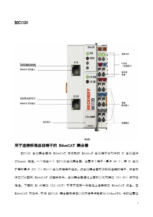
BK1120于连接标准总线端子的 EtherCAT 耦合器off 总线端子系列中的 K 总线组件(KLx 用BK1120 总线耦合器将 EtherCAT 与成熟的 Beckh xxx) 相连。
一个站由一个 BK1120总线耦合器、任意多个端子(最多 64 个,带 K 总线扩展时最多 255 个)和一个总线末端端子组成。
该总线耦合器可识别所连接的端子,并自动将它们分配到 EtherCAT 过程映像中。
总线耦合器通过上面的以太网接口(X1 IN)与网络相连。
下面的 RJ 45接口(X2 OUT)可用于在同一条电缆上连接其它 EtherCAT 设备。
在 EtherCAT 网络中,可将 BK1120 耦合器安装在以太网信号传输部分(100baseTX) 中的任意位置,但不能直接与交换机相连。
总线耦合器 BK1000(用于 K 总线组件)或 EK1000(用于 E 总线部件)可直接与交换机相连。
技术数据 BK1120将标准总线在 EtherCAT 系统中的任务 端子 (KLxxxx) 连接到 100baseTX EtherCAT网络64(若总线端子数量 通过 KL9020 和 KL9050 K 总线扩展接口,可达255 个)数字量 I/O 信号 入/输出1020 点输模拟量 I/O 信号 128 点输入/输出数据传输介质 Ethernet CAT 5 电缆模块之间的距离 100 m (100baseTX)协议 EtherCAT100 Mbit/传输速率 s配置方式 KS2000 软件,或通过 EtherCAT (ADS)总线连接 2 个 RJ 45 接口电源 24 V DC (-15 % /+20 %)70 mA +(E 总线总电流输入电流 )/4,最大 500 mAK 总线供电 最大 1750 mA电源触点 最大 24 V DC,最大10 A电气隔离 500 Vrms(电源触点/供电电压/以太网)EK1100EtherCAT 耦合器EtherCAT 与 EtherCAT 端子 (ELxxxx) 相连。
爱达顿199162商品说明书
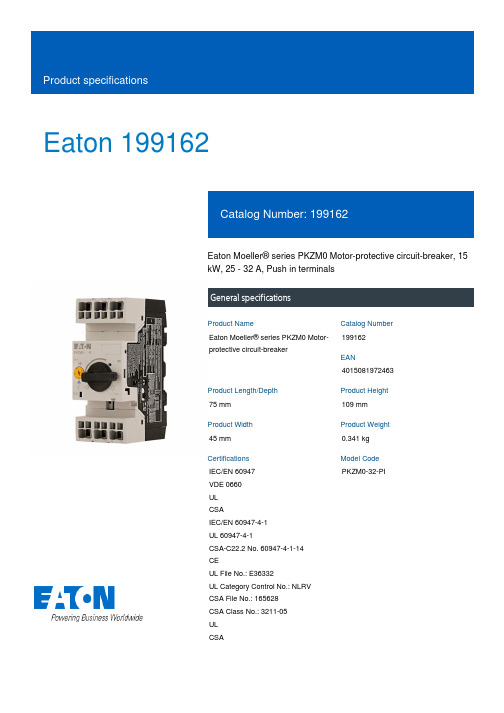
Eaton 199162Eaton Moeller® series PKZM0 Motor-protective circuit-breaker, 15kW, 25 - 32 A, Push in terminalsGeneral specificationsEaton Moeller® series PKZM0 Motor-protective circuit-breaker199162401508197246375 mm109 mm45 mm0.341 kgIEC/EN 60947VDE 0660ULCSAIEC/EN 60947-4-1UL 60947-4-1CSA-C22.2 No. 60947-4-1-14 CEUL File No.: E36332UL Category Control No.: NLRV CSA File No.: 165628CSA Class No.: 3211-05ULCSA PKZM0-32-PIProduct Name Catalog NumberEANProduct Length/Depth Product Height Product Width Product Weight Certifications Model CodeTurn buttonPhase-failure sensitivity (according to IEC/EN 60947-4-1, VDE 0660 Part 102)Motor protectionPhase failure sensitiveThree-pole 100,000 operations100,000 OperationsDIN rail (top hat rail) mounting optionalCan be snapped on to IEC/EN 60715 top-hat rail with 7.5 or15 mm height.40 Operations/hIII3Motor protective circuit breakerFinger and back-of-hand proof, Protection against direct contact when actuated from front (EN 50274)6000 V AC25 g, Mechanical, according to IEC/EN 60068-2-27, Half-sinusoidal shock 10 msAlso motors with efficiency class IE3Branch circuit: Suitable for group installations, (UL/CSA)-5 - 40 °C to IEC/EN 60947, VDE 0660≤ 0.25 %/K, residual error for T > 40°-25 - 55 °C, Operating rangeMotor starter combinations type MSC...Actuator type Features Functions Number of poles Lifespan, electricalLifespan, mechanicalMounting MethodMounting positionOperating frequencyOvervoltage categoryPollution degreeProduct categoryProtectionRated impulse withstand voltage (Uimp) Shock resistanceSuitable forTemperature compensationUsed withMax. 2000 m-25 °C55 °C25 °C40 °C40 °C80 °CDamp heat, cyclic, to IEC 60068-2-30 Damp heat, constant, to IEC 60068-2-781 x (1 - 6) mm²18 - 812 mm50 Hz60 Hz32 A7.5 kW15 kW690 V690 V32 A496 A, Irm, Setting range max. ± 20% tolerance, Trip blocksBasic device fixed 15.5 x Iu, Trip Blocks7.5 HP5 HP10 HP20 HP25 HPAltitude Ambient operating temperature - min Ambient operating temperature - max Ambient operating temperature (enclosed) - min Ambient operating temperature (enclosed) - max Ambient storage temperature - min Ambient storage temperature - max Climatic proofingTerminal capacity (flexible)Terminal capacity (solid/stranded AWG)Stripping length (main cable)Rated frequency - min Rated frequency - max Rated operational current (Ie)Rated operational power at AC-3, 220/230 V, 50 Hz Rated operational power at AC-3, 380/400 V, 50 Hz Rated operational voltage (Ue) - min Rated operational voltage (Ue) - max Rated uninterrupted current (Iu)Short-circuit releaseAssigned motor power at 200/208 V, 60 Hz, 3-phase Assigned motor power at 230/240 V, 60 Hz, 1-phase Assigned motor power at 230/240 V, 60 Hz, 3-phase Assigned motor power at 460/480 V, 60 Hz, 3-phase Assigned motor power at 575/600 V, 60 Hz, 3-phasePush in terminals032 A32 AOverload trigger: tripping class 10 A 9.56 W0 W0 W0 WMeets the product standard's requirements.Meets the product standard's requirements.Meets the product standard's requirements.Meets the product standard's requirements.Meets the product standard's requirements.Does not apply, since the entire switchgear needs to be evaluated.Does not apply, since the entire switchgear needs to be evaluated.Meets the product standard's requirements.Connection Number of auxiliary contacts (change-over contacts)Number of auxiliary contacts (normally closed contacts)Number of auxiliary contacts (normally open contacts)Overload release current setting - min Overload release current setting - max Tripping characteristic Equipment heat dissipation, current-dependent PvidHeat dissipation capacity PdissHeat dissipation per pole, current-dependent PvidStatic heat dissipation, non-current-dependent Pvs10.2.2 Corrosion resistance10.2.3.1 Verification of thermal stability of enclosures10.2.3.2 Verification of resistance of insulating materials to normal heat10.2.3.3 Resist. of insul. mat. to abnormal heat/fire by internal elect. effects10.2.4 Resistance to ultra-violet (UV) radiation10.2.5 Lifting10.2.6 Mechanical impact10.2.7 InscriptionsDoes not apply, since the entire switchgear needs to be evaluated.Meets the product standard's requirements.Does not apply, since the entire switchgear needs to be evaluated.Does not apply, since the entire switchgear needs to be evaluated.Is the panel builder's responsibility.Is the panel builder's responsibility.Is the panel builder's responsibility.Is the panel builder's responsibility.Is the panel builder's responsibility.The panel builder is responsible for the temperature rise calculation. Eaton will provide heat dissipation data for the devices.Is the panel builder's responsibility. The specifications for the switchgear must be observed.Is the panel builder's responsibility. The specifications for the switchgear must be observed.The device meets the requirements, provided the information in the instruction leaflet (IL) is observed.Motor Starters in System xStart - brochureSave time and space thanks to the new link module PKZM0-XDM32MEProduct Range Catalog Switching and protecting motorsSwitching and protecting motors - catalogDA-DC-00004889.pdfDA-DC-00004919.pdf121X042121X002eaton-manual-motor-starters-pkz-dimensions.epseaton-manual-motor-starters-pkz-dimensions-002.epseaton-manual-motor-starters-pkzm-pkzm0-dimensions.epsETN.PKZM0-32-PI.edzIL122024ZUWIN-WIN with push-in technologymotorschutzschalter_bis_32a_pi.dwgpkzm0_pi.stp10.3 Degree of protection of assemblies10.4 Clearances and creepage distances10.5 Protection against electric shock10.6 Incorporation of switching devices and components 10.7 Internal electrical circuits and connections10.8 Connections for external conductors10.9.2 Power-frequency electric strength10.9.3 Impulse withstand voltage10.9.4 Testing of enclosures made of insulating material 10.10 Temperature rise10.11 Short-circuit rating10.12 Electromagnetic compatibility10.13 Mechanical function BrochuresCatalogues Declarations of conformity DrawingseCAD modelInstallation instructions Installation videosmCAD modelEaton Corporation plc Eaton House30 Pembroke Road Dublin 4, Ireland © 2023 Eaton. All rights reserved. Eaton is a registered trademark.All other trademarks areproperty of their respectiveowners./socialmedia。
Belimo 产品B216 型号15 技术数据表说明书

B216•Stainless Steel Ball and StemType overviewType DNB21615Technical dataFunctional data Valve size0.5" [15]Fluid chilled or hot water, up to 60% glycolFluid Temp Range (water)0...250°F [-18...120°C]Body Pressure Rating600 psiClose-off pressure ∆ps200 psiFlow characteristic equal percentageServicing maintenance-freeFlow Pattern2-wayLeakage rate0% for A – ABControllable flow range75°Cv16No Characterized Disc TRUECv Flow Rating A-port: as stated in chart B-port: 70% of A – ABCvMaterials Valve body Nickel-plated brass bodyStem stainless steelStem seal EPDM (lubricated)Seat PTFECharacterized disc No Disc (full flow)Pipe connection NPT female endsO-ring EPDM (lubricated)Ball stainless steelSuitable actuators Non-Spring TRLRB(X)NRSpring TFRB(X)LFSafety notesWARNING: This product can expose you to lead which is known to the State of California tocause cancer and reproductive harm. For more information go to B216ApplicationMode of operationProduct featuresThis valve is typically used in air handling units on heating or cooling coils, and fan coil unit heating or cooling coils. Some other common applications include Unit Ventilators, VAV box re-heat coils and bypass loops. This valve is suitable for use in a hydronic system with variable flow.Flow/Mounting detailsTwo-way valves should be installed with thedisc upstream.Product featuresSY7~8 Replacement HandwheelDimensionsType DN B21615LRB, LRXAB C D E F H1H29.4" [239]2.4" [60]5.6" [141]5.0" [127]1.3" [33]1.3" [33]1.2" [30]1.1" [28]TRAB C D E F 3.7" [95]2.4" [60]5.2" [132]4.6" [117]1.3" [33]1.3" [33]B216TFRB, TFRXA B C D E F6.6" [167] 2.4" [60] 5.5" [139] 4.7" [120] 1.5" [39] 1.5" [39]LFA B C D E F7.9" [200] 2.4" [60] 6.1" [154] 5.5" [140] 1.3" [33] 1.3" [33]ARB N4, ARX N4, NRB N4, NRX N4A B C D E F11.4" [289] 2.4" [60]7.7" [196]7.0" [179] 3.1" [80] 3.1" [80]FootnotesNEMA 4X, Modulating Control, Non-Spring Return, 24 V, for DC 2...10 V or 4...20 mATechnical dataElectrical dataNominal voltageAC/DC 24 V Nominal voltage frequency 50/60 Hz Power consumption in operation 3.5 W Power consumption in rest position 0.6 WTransformer sizing 5 VA (class 2 power source)Electrical Connection Screw terminal (for 26 to 14 GA wire), 1/2" conduit connectorOverload Protectionelectronic throughout 0...95° rotation Functional dataOperating range Y 2...10 VOperating range Y note 4...20 mA w/ ZG-R01 (500 Ω, 1/4 W resistor)Input Impedance 100 kΩ for 2...10 V (0.1 mA), 500 Ω for 4...20 mA Position feedback U 2...10 V Position feedback U note Max. 1 mADirection of motion motor selectable with switch 0/1Manual override external push button Angle of rotation Max. 90°Angle of rotation note adjustable with mechanical stop Running Time (Motor)90 s / 90°Noise level, motor 45 dB(A)Position indicationpointer Safety dataDegree of protection IEC/EN IP66/67Degree of protection NEMA/UL NEMA 4XEnclosure UL Enclosure Type 4XAgency ListingcULus acc. to UL60730-1A/-2-14, CAN/CSA E60730-1:02, CE acc. to 2014/30/EU and 2014/35/EU Quality Standard ISO 9001Ambient temperature -22...122°F [-30...50°C]Ambient temperature note -40...50°C for actuator with integrated heating Storage temperature -40...176°F [-40...80°C]Ambient humidity Max. 100% RH Servicingmaintenance-freeMaterialsHousing material Die cast aluminium and plastic casing†Rated Impulse Voltage 800V, Type of action 1.AA, Control Pollution Degree 3AccessoriesElectrical accessories Description TypeBattery backup system, for non-spring return models NSV24 USBattery, 12 V, 1.2 Ah (two required)NSV-BATAuxiliary switch 1 x SPDT add-on S1AAuxiliary switch 2 x SPDT add-on S2AFeedback potentiometer 140 Ω add-on, grey P140A GRFeedback potentiometer 1 kΩ add-on, grey P1000A GRFeedback potentiometer 10 kΩ add-on, grey P10000A GRFeedback potentiometer 2.8 kΩ add-on, grey P2800A GRFeedback potentiometer 500 Ω add-on, grey P500A GRFeedback potentiometer 5 kΩ add-on, grey P5000A GR Electrical installationINSTALLATION NOTESProvide overload protection and disconnect as required.Actuators may be connected in parallel. Power consumption and input impedance must beobserved.Actuators may also be powered by DC 24 V.Only connect common to negative (-) leg of control circuits.A 500 Ω resistor (ZG-R01) converts the 4...20 mA control signal to 2...10 V.Actuators are provided with a numbered screw terminal strip instead of a cable.Meets cULus requirements without the need of an electrical ground connection.Warning! Live electrical components!During installation, testing, servicing and troubleshooting of this product, it may be necessaryto work with live electrical components. Have a qualified licensed electrician or other individualwho has been properly trained in handling live electrical components perform these tasks.Failure to follow all electrical safety precautions when exposed to live electrical componentscould result in death or serious injury.Wiring diagrams2...10 V / 4...20 mA ControlDimensions。
SIMATIC NET 工业以太网交换机 SCALANCE XC-200 操作说明说明书

SIMATIC NET工业以太网交换机SCALANCE XC-200操作说明02/2023法律资讯警告提示系统为了您的人身安全以及避免财产损失,必须注意本手册中的提示。
人身安全的提示用一个警告三角表示,仅与财产损失有关的提示不带警告三角。
警告提示根据危险等级由高到低如下表示。
危险表示如果不采取相应的小心措施,将会导致死亡或者严重的人身伤害。
警告表示如果不采取相应的小心措施,可能导致死亡或者严重的人身伤害。
小心表示如果不采取相应的小心措施,可能导致轻微的人身伤害。
注意表示如果不采取相应的小心措施,可能导致财产损失。
当出现多个危险等级的情况下,每次总是使用最高等级的警告提示。
如果在某个警告提示中带有警告可能导致人身伤害的警告三角,则可能在该警告提示中另外还附带有可能导致财产损失的警告。
合格的专业人员本文件所属的产品/系统只允许由符合各项工作要求的合格人员进行操作。
其操作必须遵照各自附带的文件说明,特别是其中的安全及警告提示。
由于具备相关培训及经验,合格人员可以察觉本产品/系统的风险,并避免可能的危险。
按规定使用 Siemens 产品请注意下列说明:警告Siemens 产品只允许用于目录和相关技术文件中规定的使用情况。
如果要使用其他公司的产品和组件,必须得到 Siemens 推荐和允许。
正确的运输、储存、组装、装配、安装、调试、操作和维护是产品安全、正常运行的前提。
必须保证允许的环境条件。
必须注意相关文件中的提示。
商标所有带有标记符号 ® 的都是 Siemens AG 的注册商标。
本印刷品中的其他符号可能是一些其他商标。
若第三方出于自身目的使用这些商标,将侵害其所有者的权利。
责任免除我们已对印刷品中所述内容与硬件和软件的一致性作过检查。
然而不排除存在偏差的可能性,因此我们不保证印刷品中所述内容与硬件和软件完全一致。
印刷品中的数据都按规定经过检测,必要的修正值包含在下一版本中。
Siemens AGDigital Industries Postfach 48 4890026 NÜRNBERG C79000-G8952-C442-14Ⓟ 02/2023 本公司保留更改的权利Copyright © Siemens AG 2016 - 2023.保留所有权利目录1简介 (7)2安全须知 (15)3安全建议 (17)4设备描述 (25)4.1产品总览 (25)4.2设备视图 (31)4.2.1SCALANCE XC206-2 (ST/BFOC) (31)4.2.2SCALANCE XC206-2 (SC) (32)4.2.3SCALANCE XC206-2G PoE (33)4.2.4SCALANCE XC206-2SFP (34)4.2.5SCALANCE XC208 (35)4.2.6SCALANCE XC208G PoE (36)4.2.7SCALANCE XC216 (37)4.2.8SCALANCE XC216-3G PoE (38)4.2.9SCALANCE XC216-4C (38)4.2.10SCALANCE XC224 (40)4.2.11SCALANCE XC224-4C (41)4.3附件 (41)4.4SELECT/SET 按钮 (47)4.5LED 指示灯 (49)4.5.1总览 (49)4.5.2“RM”LED (50)4.5.3“SB”LED (50)4.5.4“F”LED (50)4.5.5LED“DM1”和“DM2” (51)4.5.6LED“L1”和“L2” (51)4.5.7端口 LED (52)4.6C-PLUG (54)4.6.1C-PLUG 的功能 (54)4.6.2更换 C-PLUG (56)4.7组合端口 (57)4.8以太网供电 (PoE) (58)4.8.1符合标准的电源和电压范围 (58)4.8.2设备的 PoE 属性 (59)4.8.3电源传输和引脚分配 (30 W) (61)SCALANCE XC-200目录4.8.4电源传输和引脚分配 (60 W) (62)4.8.5组态 (62)5组装和拆卸 (63)5.1安装的安全注意事项 (63)5.2关于 SFP 收发器的一般说明 (66)5.3安装类型 (66)5.4在 DIN 导轨上安装 (67)5.4.1基于固定板的凹顶导轨安装 (67)5.4.2无固定板时的凹顶导轨安装 (69)5.5在标准 S7-300 导轨上安装 (70)5.5.1在带有固定板的标准导轨 S7-300 上安装 (70)5.5.2在不带固定板的标准导轨 S7-300 上安装 (71)5.6在标准导轨 S7-1500 上安装 (72)5.6.1在带有固定板的标准导轨 S7-1500 上安装 (72)5.6.2在不带固定板的标准导轨 S7-1500 上安装 (74)5.7基于固定板的墙式安装 (75)5.8更改固定销的位置 (76)5.9拆卸 (77)6连接 (79)6.1不使用 PoE 的设备的安全注意事项 (79)6.2PoE 设备的安全注意事项 (80)6.3有关在危险场所使用的安全注意事项 (82)6.4附加说明 (85)6.5接线规则 (86)6.624 V DC 电源 (87)6.754 V DC 电源 (88)6.8信号触点 (90)6.9功能性接地 (91)6.10串口 (92)6.11工业以太网 (94)6.11.1电气 (94)6.11.2光纤 (95)SCALANCE XC-200目录7维护和清洁 (97)8故障排除 (99)8.1使用 TFTP 下载新固件(无需 WBM 和 CLI) (99)8.2恢复出厂设置 (100)9技术规范 (101)9.1SCALANCE XC206-2 (ST/BFOC) 的技术规范 (101)9.2SCALANCE XC206-2 (SC) 的技术规范 (104)9.3SCALANCE XC206-2G PoE 的技术规范 (107)9.4SCALANCE XC206-2G PoE (54 V) 的技术规范 (110)9.5SCALANCE XC206-2G PoE EEC (54 V) 的技术规范 (113)9.6SCALANCE XC206-2SFP 的技术规范 (116)9.7SCALANCE XC206-2SFP G 的技术规范 (119)9.8SCALANCE XC206-2SFP EEC 的技术规范 (122)9.9SCALANCE XC206-2SFP G EEC 的技术规范 (125)9.10SCALANCE XC208 的技术规范 (128)9.11SCALANCE XC208G 的技术规范 (130)9.12SCALANCE XC208G PoE 的技术规范 (132)9.13SCALANCE XC208G PoE (54 V) 的技术规范 (134)9.14SCALANCE XC208EEC 的技术规范 (136)9.15SCALANCE XC208G EEC 的技术规范 (138)9.16SCALANCE XC216 的技术规范 (140)9.17SCALANCE XC216EEC 的技术规范 (142)9.18SCALANCE XC216-3G PoE 的技术规范 (144)9.19SCALANCE XC216-3G PoE (54 V) 的技术规范 (146)9.20SCALANCE XC216-4C 的技术规范 (150)9.21SCALANCE XC216-4C G 的技术规范 (153)9.22SCALANCE XC216-4C G EEC 的技术规范 (156)9.23SCALANCE XC224 的技术规范 (159)9.24SCALANCE XC224-4C G 的技术规范 (161)9.25SCALANCE XC224-4C G EEC 的技术规范 (164)9.26机械稳定性(运行时) (167)SCALANCE XC-200目录9.27射频辐射符合 NAMUR NE21 标准 (167)9.28电缆长度 (167)9.29交换特性 (168)10尺寸图 (171)11证书和认证 (179)索引 (189)SCALANCE XC-200简介1操作说明的用途这些操作说明适用于 SCALANCE XC-200 系列产品的安装和连接。
TLE2161AMFK中文资料
IMPORTANT NOTICETexas Instruments and its subsidiaries (TI) reserve the right to make changes to their products or to discontinue any product or service without notice, and advise customers to obtain the latest version of relevant information to verify, before placing orders, that information being relied on is current and complete. All products are sold subject to the terms and conditions of sale supplied at the time of order acknowledgement, including those pertaining to warranty, patent infringement, and limitation of liability.TI warrants performance of its semiconductor products to the specifications applicable at the time of sale in accordance with TI’s standard warranty. Testing and other quality control techniques are utilized to the extent TI deems necessary to support this warranty. Specific testing of all parameters of each device is not necessarily performed, except those mandated by government requirements.CERTAIN APPLICATIONS USING SEMICONDUCTOR PRODUCTS MAY INVOLVE POTENTIAL RISKS OF DEATH, PERSONAL INJURY, OR SEVERE PROPERTY OR ENVIRONMENTAL DAMAGE (“CRITICAL APPLICATIONS”). TI SEMICONDUCTOR PRODUCTS ARE NOT DESIGNED, AUTHORIZED, OR WARRANTED TO BE SUITABLE FOR USE IN LIFE-SUPPORT DEVICES OR SYSTEMS OR OTHER CRITICAL APPLICATIONS. INCLUSION OF TI PRODUCTS IN SUCH APPLICATIONS IS UNDERSTOOD TO BE FULLY AT THE CUSTOMER’S RISK.In order to minimize risks associated with the customer’s applications, adequate design and operating safeguards must be provided by the customer to minimize inherent or procedural hazards.TI assumes no liability for applications assistance or customer product design. TI does not warrant or represent that any license, either express or implied, is granted under any patent right, copyright, mask work right, or other intellectual property right of TI covering or relating to any combination, machine, or process in which such semiconductor products or services might be or are used. TI’s publication of information regarding any third party’s products or services does not constitute TI’s approval, warranty or endorsement thereof.Copyright © 1998, Texas Instruments Incorporated。
78 ZIEHL industrie-elektronik UFR1001E 电压频率监测器商品说明

Voltage Monitoring Type UFRThe grid- and plant protection de-vice UFR1001E monitors voltage and frequency in plants for own generation of electricity. It com-plies with the requirements of VDE-AR-N 4105:2018-11, VDE-AR-N 4110:2018-11, G98, G99, ÖVE/ÖNORM E 8001-4-712:2009 and other standards for generators connected to the public grid.The UFR1001E is a dual-channel device and thus one-fault-proof.Voltage and Frequency Relay UFR1001EGrid- and Plant Protection VDE-AR-N 4105 and 4110, ÖVE-standard, G98 + G99, DIN V VDE 0126-1-1, VFR2013/2014, NRS 0972-1:2017 Ed 2, Synergrid C10/C11UFR1001E••••••••NEW: VDE-AR-N 4105:2018-11, VDE-AR-N 4110:2018-11Part number:S222296The function of the output-relays and of the connected switches can be monitored with feed-back contacts. When a connected switch does not switch off, the UFR does not switch on again. When a switch does not switch on it makes 2 restarts and thus improves availability of monitored plant.The limits are pre-set according to VDE-AR-N 4105-2018-11, VDE-AR-N 4105:2018-11 and other standards. They can be changed if required and be protected with a code and/or a seal.With a 2-step test both channels can be tested indivi-dually and the triggering time of connected switches is measured.The standby input allows a remote shutoff e.g. with a RCR.Under and overvoltage monitoring 15…520 VMeasuring phase-neutral or phase-phaseMonitoring of under- and overfre-quency 45…65 HzMonitoring of quality of voltage (10-minutes-average)Monitoring of vector shift 2…65°Monitoring of rate of change of frequency (ROCOF, df/dt) 0,100...5,000 Hz/sOne-fault-proof with monitoring of connected switches (defeatable), 2 automatic restarts at errorPassive anti-islanding pro-tection acc. to ch. 6.5.3 and app. D2Switching delay adjustable 0.05 … 300 sSwitching back delay adju-stable 0 … 6.000 s Preset values acc. toVDE-AR-N 4105:2018-11 (Pr2), VDE-AR-N 4105-2011-08 (Pr1)VDE-AR-N 4110:2018-11 (PR11-14) and BDEW (Pr 3-6)G98 (G83/2) and G99 (G59/3) for Great Britain ÖVE standard for AustriaVSE/EEA-CH 2014 for SwitzerlandAlarm counter for 100 alarms (trip value, cause and rel. time stamp)Record of added times of alarmsInput for standby with counter and recording of time Test button and simulation with measuring of switching-timesSealing. All values can be read-out when sealed Easy installation and programming with pre-set programsHousing for DIN-rail-mount, 105 mm wide, mounting height 66 mm•••••••••••-----Certificate of conformity Grid and Plant protection acc. to VDE-AR-N 4105 2011-08 and 2018-11 "Plants for generati-on of own energy in low voltage grid"Cerfiticate of conformity Grid and Plant protection acc. to BDEW requirement "Plants for generation of own energy in medium voltage grid"Certificates:CertificateÖVE/ÖNORM E 8001-4-712:2009-12, Anhang ACertificate of compliance DIN V VDE 0126-1-1Certificate de conformitéDIN V VDE 0126-1-1, VFR2013/VFR 2014Certificate of complianceNRS 097-2-1:2010 ed 2.0 South Africa approved Synergrid C10/C11approved Energex RED STD00233accepted by TepcoCertificate of compliance EN 50438:2013Certificate of compliance G59/3:2013, G83/2:2012, G99/1-1+2+3:2018 and G98/1-1+2:2018RD1699:2011 / RD413:2014Technical Data UFR1001EVoltage Monitoring Type UFR2AC/DC 24-270 V, 0/45...65 Hz, <5VA DC: 20,4...297 V, AC: 20,4...297 V 2 change-over contacts see operating manualAC 15...530 V (< 5 V display: 0)AC 15...520 VAC 10...310 V (< 5 V display: 0)AC 15...300 V true RMSadjustable 1,0...180 Vwith neutral: ±0,6% of measured value without neutral: ±0,8% of measured value >100V: -1 digit (resolution 1 V) <100V: -1 digit (resolution 0,1 V)3-phase with / without neutraladjustable 0,05 (± 15ms)...300,0 sadjustable 0 (approx. 200 ms)...6.000 s 40...70 Hz45,00...65,00 Hz 0,05...10,00 Hz ± 0,04 Hz ± 1 digitadjustable 0,05 (± 15ms)...300,0 s adjustable 0 (>200 ms)...6.000 s 0...90,0°2,0...65,0°< 50 msadjustable 3...240 s adjustable 2...20 s0,100...5,000 Hz/s, 4...50 cycles DC 4,5...27 Vmax. 20 mA / output DC 15...35 Vadjustable 0,5...99,0 sEN 602554000 V III 2300 V 100 %-20 °C...+55 °C -25 °C...+70 °C3K5 (except condesation and formation of ice)EN 61 000-6-2EN 61 000-6-3V690 x 105 x 69 mm, mounting height 66 mm IP30IP20DIN-rail 35 mm according to EN 60 715 or screws M4ca. 250 gPower supply Rated supply voltage UsMeasurement phase-phase Setting range phase-phaseMeasuring voltage phase-neutral Setting range phase-neutral Measurement method HysteresisMeasurement accuracy Accuracy of display Measurement functions Switching-delay (dAL)Switching-back-delay (doF)Measurement range Setting range HysteresisMeasurement accuracy Switching delay (dAL)Switching-back-delay (doF)Measurement range Setting rangeSwitching-delay (dAL)Switching-back-delay (doF)Delay at Us on Setting range Voltage I1Current Q1...Q5Voltage Y0...Y1/2Switching time connected swit-chesRated impulse voltage Overvoltage category Pollution degreeRated Insulation voltage Ui Operating timeOperating temperature Storage temperatureClimatic conditions (IEC/EN 60721-3-3)EMC - immunity EMC - emissionDesignDimensions (h x w x d) Protection housing Protection terminals Attachment WeightHousingRelay output Test ConditionsVoltageFrequencyVector-ShiftDigital outputs insulated Input Feed-back-contactsROCOF (df/dt)。
ATEX和IECEx合规的温度传感器(-30到180°F)说明书

4. ATEX Compliant 0518 II 2 G Ex d IIC T6 Gb -20 ≤ Tamb ≤63.6°C. Process≤63.6°C. Typedrain and IP 54 with drain. ATEX Standards: EN 60079-0: 2009; EN60079-1: 2007.For Ex≤63.6°C. IECEx Certificate of Conformity: IECEx DEK 11.0095 X; IECEx Standards:IEC 60079-0: 2007; IEC 60079-1: 2007.*Options that do not have ATEX and IECEx.Attention: Units without the “AT” suffix are not Directive 2014/34/EU (ATEX) compliant. These units are not intended for use in potentially hazardous atmospheres in the EU.These units may be CE marked for other Directives of the EU.Certificate No. IECEx 11.0095 X for conditions of safe use for compliant units.1. Determine the low and high setpoint pressures.from the pressure port a pressure gage of ©Copyright 2016 Dwyer Instruments, Inc. Printed in U.S.A. 4/16FR# 89-442112-00 Rev. 7Limited Warranty:The Seller warrants all Dwyer Instruments and equipment to be free from defects in workmanship or material under normal use and service for a period of one year from date of shipment. Liability under this warranty is limited to repair or replacement F.O.B. factory of any parts which prove to be defective within that time or repayment of the purchase price at the Seller’s option provided the instruments have been returned, transportation prepaid, within one year from the date of purchase. All technical advice, recommendations and services are based on technical data and information which the Seller believes to be reliable and are intended for use by persons having skill and knowledge of the business, at their own discretion. In no case is Seller liable beyond replacement of equipment F.O.B. factory or the full purchase price. This warranty does not apply if the maximum ratings label is removed or if the instrument or equipment is abused, altered,used at ratings above the maximum specified, or otherwise misused in any way.THIS EXPRESS LIMITED WARRANTY IS IN LIEU OF AND EXCLUDES ALL OTHER REPRESENTATIONS MADE BY ADVERTISEMENTS OR BY AGENTS AND ALL OTHER WARRANTIES, BOTH EXPRESS AND IMPLIED. THERE ARE NO IMPLIED WARRANTIES OF MERCHANTABILITY OR OF FITNESS FOR A PARTICULAR PURPOSE FOR GOODS COVERED HEREUNDER.Buyers Remedies: THE BUYER’S EXCLUSIVE AND SOLE REMEDY ON ACCOUNT OF OR IN RESPECT TO THE FURNISHING OF NONCONFORMING OR DEFECTIVE MATERIAL SHALL BE TO SECURE REPLACEMENT THEREOF AS AFORESAID, THE SELLER SHALL NOT IN ANY EVENT BE LIABLE FOR THE COST OF ANY LABOR EXPENDED ON ANY SUCH MATERIAL OR FOR ANY SPECIAL, DIRECT, INDIRECT, OR CONSEQUENTIAL DAMAGES TO ANYONE BY REASON OF THE FACT THAT IT SHALL HAVE BEEN NON-CONFORMING OR DEFECTIVE.。
fluke中文使用手册1621
i
1621 用户手册
ii
表目录
表
1. 2. 3. 4.
标题
第页
可选附件............................................................................................ 4 特性和功能........................................................................................ 6 显示屏................................................................................................ 8 故障诊断............................................................................................ 14
开箱
在打开装运箱取出测试仪及其附件时,请参阅“附件”部分。请将包装 材料妥善保管供日后运输之需。 检查是否有缺件并仔细查看设备是否有如裂纹、凹痕或部件弯曲等损坏 现象。如果发现物品缺少或任何明显的机体损坏,请致电 Fluke 寻求协 助。请参阅“服务”部分获取 Fluke 的联系信息。
包装
运输测试仪时必须使用原始的包装材料。
特性和功能序号说明ahc2插孔用于连接辅助接地极bsp2插孔用于连接探针cec1插孔用于连接接地极dlcd显示屏见lcd显示屏e支架位于背面用于直立支撑测试仪f旋转开关用于选择测量功能极限模式和开机关机g皮套保护测试仪不受损坏h电池仓位于背面可容纳一节9v电池idisplay显示按钮用于选择测量结果和其它功能jstart开始按钮用于触发测量功能和其它功能6earthgroundtester特性软件要查看软件版本可将旋转开关设至off关闭位置然后按住start开始并将旋转开关设到任何on开启位置3pole2pole或limit
Elko EP 设备名称和型号说明书

SOU-2cos φ ≥ 0.95M M HAL.230VKM MAC12250V / 1ADC14x AC1250V / 8AAC13xAC2250V / 5AAC14250V / 4AAC3250V / 4AAC15250V / 3AAC5b250WDC530V / 2AAC6a250V /4ADC1230V / 8AAC7b250V / 1ADC1330V / 2A02-28/2017 Rev.: 1xDC330V / 3AxDC130V / 8A15 16 18A1 A2 T1 T1 G GUnT1GT1GA1A21516189101112131415161718192015234678Made in Czech RepublicELKO EP, s.r.o.Palackého 493769 01 Holešov, VšetulyCzech RepublicTel.: +420 573 514 211Twilight digital switch with integrated time switch CharacteristicsDescriptionSymbol ConnectionType of loadMat. contacts AgSnO2,contact 8 AType of loadMat. contacts AgSnO2,contact 8 AAC5auncompensatedAC5acompensatedEN• It is used to control lighting based on the level of ambient light intensity and realtime (a combination of twilight switch / light switch and switching clock in oneproduct).• With the possibility to block the function of the twilight switch at a time when thelighting is undesirable or uneconomical.• External light sensor with IP65 protection, adapted for wall mounting (sensor hold-er included) or panel.• Backlit LCD display.• Backup of the set time using the battery.• Easily replace the backup battery without disassembling the device.• Switching mode AUTO:PROGRAM > according to the set program or RANDOM >switches randomly - simulation of the presence of people.• PROGRAM:LIGHT > switches according to the set level of illumination or TIME PRO-GRAM > switches according to the set time program.• Switching mode HOLIDAYS > blocking of the set program.• Switching mode MANUAL > permanently on or off.• Programming can also be done in backup mode (battery power).• In backup mode, relay output contacts do not work.• Automatic transition winter/daylight saving time (by region).• Display languages - CZ / SK / EN / ES / PL / HU / RU.SensorCONTROL OF A DISPLAY WITH BACKLIGHTPower on: Display is illuminated with a backlight for 10 seconds from the last button press.The display continuously shows the settings – date, time, day of the week, contact stateand programme. Permanent on / off is activated by simultaneous presses of the MAN,ESC, OK buttons.After activating the permanent on/off, the display will fl ash briefl y.Backup mode: After 2 minutes, the display switches to the sleep mode, i.e. shows no infor-mation. The display can be activated by pressing any button.1. Supply voltage terminals2. Display with back-light3. Place for seal4. Backup battery plug-in5. Output contact (15-16-18)6. Terminals - sensor (T1)7. Shield connection terminals(if shielded cable is used)8. Control buttons9. Indicates the day in the week10. Status indication11. Display of data / settings menu / light intensity12. ime display13. Control button PRG / +14. Reset15. Control button MAN / -16. Operating modes indication17. 12/24 hours format18. Indication of the switch program19. Control button ESC20. Control button OK. Switches display date / lightintensitySOU-2OK+_OK+_ESCOKoptionslanguageESPAnOLLIGHTTechnical parameters * ERROR - sensor short circuitLight sensorPhotosensor SKS-200 is external and is connected to terminals T1. Sensor is installable to panel (by screw-able transparent cover) to opening with diameter 20 mm. A part of the sensor is a plas-tic holder for placing into the wall or to another place. Length of a line connector to the sensor cannot be more than 50 m. Doublecure cable can be used as wire diameter min. 0.2 - 0.75 mm 2 / with sleeve: 0.25 - 0.34 mm 2 . Protection degree is IP65.To keep this protection:- photosensor SKS-200 cover must be sealed by a rubber circle (part of the sensor)- cable must be of round cross-selection- the opening must be tight to the used cableMode precendencemode precedencedisplay output mode⑥⑥⑥ON / OFF manual control⑥⑥ON / OFF holiday mode ⑥ON / OFF time program lightlightmode with the highest priorityLanguage settingsLight and Time Program can work at the same time on a single channel.Language selectionlanguageoptionsControl descriptionentrance into programming menu+_browsing in menu setting of values+_quick shifting during setting of valuesOK entrance into required menu confi rmationswitch. between display ESCone level upa step backESCback to the starting menuDevice diff ers short and long button press. In the manual marked as:- short button press (<1s) - long button press (>1s)After 30s of inactivity (from the last press of any button) will device automatically returns into starting menu.In the start screen, press OK to toggle between displaying the date or light intensity.The measured value after exceeding 999 is measured in the hundreds of thousands by display-ing the letter …k“ at the end. A comma separates the thousands line.Supply terminals:Supply voltage tolerance:Consumption:Supply voltage tolerance:Backup battery type:OutputNumber of contacts:Rated current:Switched capacity:Switched voltage:Dissipated power (max.):Mechanical life:Electrical life (AC1):Time circuitAccuracy:Minimum interval:Program data stored for:Program circuitIllumination range:Sensor failure indication:Number of program places:Program:Other dataOperating temperature Storage temperature:Dielectrical strength:Operating position:Mounting:Protection degree:Overvoltage cathegory:Pollution degree:Max. cable size (mm 2):Dimensions:Weight:Dimension of sensor:Weight sensor:Standards:A1 - A2AC 230V (50-60 Hz)4 VA / 1.7 W -15 %; +10 %CR 2032 (3V)1x changeover (AgSnO 2)8 A/AC12000 VA/AC1, 240 W/DC250V AC/30V DC0.6 W 30.000.000 ops. 100.000 ops.max. ±1s/ day at 23 °C1 min min. 10 years 10-50000 lx displayed on LCD *100daily, weakly, yearly-10 °C to +55 °C (-4 °F to 131 °F)-30 °C to +70 °C (-22 °F to 158 °F)4 kV (supply - output)3.5 kV (supply - sensor)any DIN rail EN 60715IP40 from front panel/IP20 terminalsIII.2max. 1x 2.5, max. 2x 1.5/with sleeve max. 1x 1.5 90 x 35 x 64 mm (3.5‘‘x 1.4‘‘x 2.5‘‘)142 g (5 oz.)58 x Ø 24 mm (2.3‘‘x Ø 0.9‘‘)16 g (0.5 oz.)EN 61812-1, EN 60669-1, EN 60669-2-115-1815-18Menu overviewLight functions setting.t1- delay time when switching ont2 - delay time when switching offThe value may be entered in a range of 10 to 50,000 lux.After exceeding a value of 9,800 lux, a period separates thethousands line.If the function light is active, then symbol …Auto“ is displayed on the screen.If the entered switching delay is shown on the display …Auto + t“.Ambient light courseSet levelDate and time settingrst day of the week.. Set the number from the set to the current date.rst day of the week.OKOKOKOKOKOKOKOKOKOKOKOKOKOKOKOKOKOKOK*Time programsetting of minutesminutesactivity on a week daymonthminuteshours setting of hoursactivity on a week daylevel or constant ON/OFFlevel or constant ON/OFFor constant ON/OFFprogram *yearly programsetting of the year setting of the month setting of the daysetting of minutessetting of hourslevel or constant ON/OFFCHANGE / DELETE . If you do not want to proceed, press ESC to go to the main settings without any change.If the program memory is full, you will see full on the display.If the programs memory is empty and you want to change or erase a program, the display will read empty.Setting the switching modesWhat you see on the display:- when a random mode is activated - Random - the symbol is lit .- vacation mode HOLIDAY:- the illuminated symbol indicates the vacation mode.- the fl ashing symbol indicates the vacation mode.- the symbol is not illuminated if the vacation mode is not set or has.- when the manual mode is activated, the symbol is lit and the manually controlled channel is fl ashing.Settings optionsTime correction:The shift unit is 0.1s per day.The numeric value refers to seconds per 10 days.Time correction is factory-set and individual for each product so that the real-time clock would run with minimum deviation. The time correction value can be arbitrarily adjusted, but after product RESET, the value returns to factory settings.onon+_on+_OK+ESCOKOKOKOK OK OKOK OK OK ESCOK+_+_OK OKOK+_+_+_+_+_OKOKOKOK+_OK+_PRG OK+_OK OKOKOKOKOKOKOKOKon+_OKOKOKOKOKOK OK OKCR2032+Performed by shortly pressing the hidden RESET button with a blunt-pointed object (e.g. a pencilor screw-driver with a diameter of at most 2 mm).The type of device and software version will be displayed for 1 second, then the device will enterdefault mode. This means that the language is set to EN, all data is zeroed (light function, time/date, user programs, device options function).Resetpress button OK to completethe deleting of all set programsin starting menu (time is shownon display) - press simultaneouslybutton and and displayannounces a notice allDeleting of all programsall16--sep-- 10Battery replacementYou can replace the battery without disassembling the device.- Eject the plug-in module with battery- Remove the original battery- Insert the new battery so that the top edge of the battery (+) is aligned with the Plug-in module- insert the plug-in module into the device - beware of polarity (+ up)16--sep-- 1016--sep-- 10WarningAn example of SOU-2 programmingSettings for switching upon exceeding the range of 1,500 lux. Settings of hysteresis at 10% and off delay at 10 min. Upon a change of the lux switching range each Friday at 12:00 p.m. to 2,000 and each Wednesday at 11:00 a.m. to 1,000 lux.lightlight time prog add addaddprog progday progday proghourhourminuteminuteintensity intensityset (lux)set (lux)set (lux)hysteresis set (%)hysteresis delay delayDevice is constructed for connection in 1-phase main alternating current voltage 230 V andmust be installed according to norms valid in the state of application. Connection according tothe details in this direction. Installation, connection, setting and servicing should be installedby qualifi ed electrician staff only, who has learnt these instruction and functions of the device.This device contains protection against overvoltage peaks and disturbancies in supply. F orcorrect function of the protection of this device there must be suitable protections of higherdegree (A, B, C) installed in front of them. According to standards elimination of disturbanciesmust be ensured. Before installation the main switch must be in position “OFF” and the deviceshould be de-energized. Don´t install the device to sources of excessive electro-magnetic in-terference. By correct installation ensure ideal air circulation so in case of permanent opera-tion and higher ambient temperature the maximal operating temperature of the device is notexceeded. For installation and setting use screw-driver cca 2 mm. The device is fully-electronic- installation should be carried out according to this fact. Non-problematic function dependsalso on the way of transportation, storing and handling. In case of any signs of destruction,deformation, non-function or missing part, don´t install and claim at your seller it is possible todismount the device after its lifetime, recycle, or store in protective dump.。
HAT2169H-EL-E中文资料
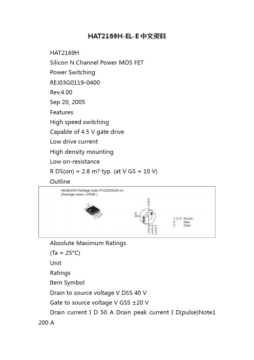
HAT2169H-EL-E中文资料HAT2169HSilicon N Channel Power MOS FETPower SwitchingREJ03G0119-0400Rev.4.00Sep 20, 2005FeaturesHigh speed switchingCapable of 4.5 V gate driveLow drive currentHigh density mountingLow on-resistanceR DS(on) = 2.8 m? typ. (at V GS = 10 V)OutlineAbsolute Maximum Ratings(Ta = 25°C)UnitRatingsItem SymbolDrain to source voltage V DSS 40 VGate to source voltage V GSS ±20 VDrain current I D 50 A Drain peak current I D(pulse)Note1 200 ABody-drain diode reverse drain current I DR 50 A Avalanche current I AP Note 2 30 A Avalanche energy E AR Note 2 72 mJ Channel dissipation Pch Note3 30 W Channel to Case Thermal Resistance θch-C 4.17 °C/WChannel te mperature Tch 150 °CStorage temperature Tstg –55 to +150 °CNotes: 1. PW ≤ 10 μs, duty cycle ≤ 1%2. Value at Tch = 25°C, Rg ≥ 50 ?3. Tc = 25°CElectrical Characteristics(Ta = 25°C)Item Symbol Min Typ Max Unit Test ConditionsDrain to source breakdown voltage V (BR)DSS 40 —— V I D = 10 mA, V GS = 0 Gate to source breakdown voltage V (BR)GSS ±20 ——V I G = ±100 μA, V DS = 0 Gate to source leak current I GSS ——±10 μA V GS = ±16 V, V DS = 0 Zero gate voltage drain current I DSS ——1 μA V DS = 40 V, V GS = 0 Gate to source cutoff voltage V GS(off) 1.0 — 2.5 V V DS = 10 V, I D = 1 mAR DS(on) — 2.8 3.5 m ? I D = 25 A, V GS = 10 V Note4 Static drain to source on stateresistance R DS(on) — 4.0 6.0 m ? I D = 25 A, V GS = 4.5 V Note4Forward transfer admittance |y fs | 39 65 — S I D = 25 A, V DS = 10 V Note4 Input capacitance Ciss — 6650 — pF Output capacitance Coss — 890 — pF Reverse transfer capacitance Crss — 360 — pF V DS = 10 V, V GS = 0, f = 1 MHz Gate Resistance Rg — 0.5 — ? Total gate charge Qg — 45 — nC Gate to source charge Qgs — 21 — nC Gate to drain charge Qgd — 10 — nC V DD = 10 V, V GS = 4.5 V, I D = 50 A Turn-on delay time t d(on) —15 — ns Rise time t r — 64 — nsTurn-off delay time t d(off) — 55 — ns Fall timet f — 9.5 — ns V GS = 10 V, I D = 25 A,V DD ? 10 V, R L = 0.4 ?, Rg = 4.7 ? Body–drain diode forward voltage V DF — 0.83 1.08 V IF = 50 A, V GS = 0 Note4 Body–drain diode reverse recovery timet rr — 40 — ns IF = 50 A, V GS = 0di F / dt = 100 A/ μsNotes: 4. Pulse testMain CharacteristicsPackage DimensionsOrdering InformationPart Name Quantity Shipping ContainerHAT2169H-EL-E 2500pcs TapingNote: For some grades, production may be terminated. Please contact the Renesas sales office to check the state of production before ordering the product. RENESAS SALES OFFICESRefer to "/en/network" for the latestand detailed information.Renesas Technology America, Inc.450 Holger Way, San Jose, CA 95134-1368, U.S.ATel: <1> (408) 382-7500, Fax: <1> (408) 382-7501Renesas Technology Europe LimitedDukes Meadow, Millboard Road, Bourne End, Buckinghamshire, SL8 5FH, U.K.Tel: <44> (1628) 585-100, Fax: <44> (1628) 585-900Renesas Technology Hong Kong Ltd.7th Floor, North T ower, World Finance Centre, Harbour City, 1 Canton Road, Tsimshatsui, Kowloon, Hong KongTel: <852> 2265-6688, Fax: <852> 2730-6071Renesas Technology Taiwan Co., Ltd.10th Floor, No.99, Fushing North Road, Taipei, TaiwanTel: <886> (2) 2715-2888, Fax: <886> (2) 2713-2999Renesas Technology (Shanghai) Co., Ltd.Unit2607 Ruijing Building, No.205 Maoming Road (S), Shanghai 200020, ChinaTel: <86> (21) 6472-1001, Fax: <86> (21) 6415-2952Renesas Technology Singapore Pte. Ltd.1 Harbour Front Avenue, #06-10, Keppel Bay Tower, Singapore 098632Tel: <65> 6213-0200, Fax: <65> 6278-8001Renesas Technology Korea Co., Ltd.Kukje Center Bldg. 18th Fl., 191, 2-ka, Hangang-ro, Yongsan-ku, Seoul 140-702, KoreaTel: <82> 2-796-3115, Fax: <82> 2-796-2145Renesas Technology Malaysia Sdn. Bhd.Unit 906, Block B, Menara Amcorp, Amcorp Trade Centre, No.18, Jalan Persiaran Barat, 46050 Petaling Jaya, Selangor DarulEhsan, MalaysiaTel: <603> 7955-9390, Fax: <603> 7955-9510。
E2SCA18-7.999M中文资料(ECLIPTEK)中文数据手册「EasyDatasheet - 矽搜」

(5 DigitsMaximum + Decimal)
HC-49/UP
规格如有更改,恕不另行通知.
CR44
.
08/08
包装选择
空白=散装,TR =卷带式
频率
负载电容
S =串联谐振 XX = XXpF并联谐振
动作模式 /水晶切割 A =基本/ AT, B =三次泛音/ AT D =基本/ BT
外形尺寸 ALL DIMENSIONS IN MILLIMETERS
建议焊盘布局 ALL DIMENSIONS IN MILLIMETERS
电气特性
频率范围频率ຫໍສະໝຸດ 差 /稳定性在工作温 度范围
工作温度范围
老化( 25°C)
存储温度范围
并联电容
绝缘电阻
驱动电平
负载电容(C
)
3.579545MHz为50.000MHz
为±50ppm /±100ppm(标准),±30ppm/为±50ppm(AT切割只),±15ppm/±30ppm(AT切割只),
环境/机械特性
PARAMETER
ESD敏感性
精细泄漏测试 可燃性 总泄漏测试 机械冲击 耐湿性 湿度敏感度 耐焊接热 抗溶剂 可焊性 温度循环 振荡
SPECIFICATION
MIL-STD-883,方法3015,1级,HBM:1500V MIL-STD-883,方法1014,条件A UL94-V0 MIL-STD-883,方法1014,条件C MIL-STD-202,方法213,条件C MIL-STD-883,法1004 J-STD-020, MSL1 MIL-STD-202,方法210,满足条件K MIL-STD-202,方法215 MIL-STD-883,方法2003 MIL-STD-883,方法1010,条件B MIL-STD-883,方法2007条件A
气相色谱法测定氨气中的甲硫醇及甲硫醚

用去离子水配制体积分数为 80 %的磷酸吸收 液 ,并以 40 mL / mi n 的流速通入高纯氮气 , 吹脱 30 ~40 mi n 除氧后备用 。 114 含氨甲硫醇和含氨甲硫醚混合气的制备
卷) [ M ] . 北京 :化学工业出版 , 1999
Recovery of Benzene fro m Wa ste Ga s by Activate d Carbon Fiber Adsorption Proce ss
L i S houx i n1 , Zhang Wenz hi2 , S ong L i m i n1 (1. Nort h China Elictric Power Universit y , Hebei Baoding 071003 , China ; 2. Hebei Zhonghuan Environmental Engineering Co . Ltd. , Hebei Baoding 071000 , China)
[ 摘要 ] 建立了测定氨气中甲硫醇及甲硫醚的气相色谱分析方法 。样品充入高纯氮气后 ,通过 磷酸吸收液脱除氨气 ,有机硫化物由氨气转移到高纯氮气中 , 收集这部分气体 , 取 110~210 mL 采用火焰光度检测填充柱气相色谱法进行分析 。方法的相对标准偏差小于 7 % ,甲硫醇和 甲硫醚的加标回收率分别为 9211 %和 8716 % ,最低检出量分别为 0111 ng 和 0117 ng ,最低检 出质量浓度分别为 0111μg/ L 和 0117μg/ L 。 [ 关键词 ] 氨气 ; 甲硫醇 ; 甲硫醚 ; 气相色谱法 [ 中图分类号 ] X502 [ 文献标识码 ] A [ 文章编号 ] 100621878 (2003) 0420231205
AF AG VW VG VF 手动平衡阀 2”-16” 钢制文丘里蝶阀 IMI FLOW DESIG

AF AGManual Balancing Valves2”-16” Steel venturi with butterfly ValveAF AGThe AccuSetter uses a low-loss venturi to obtain a measurement. S. The butterfly has a 2” extended neck above the memory stop for sizes 2” to 6” and a gear operator on 8” to 16” sizes. The total pressure drop added to the pump head seldom formula on Form F199. Flow measurement can be obtained with>Low Loss VenturiMeasure with 3% accuracy >Infinite PositionFine adjustment>Memory Stop2” - 8”Technical descriptionApplication:Hydronic Balancing Functions:Balancing, measurement, shut-off Dimensions:2” - 6”, 8”,10”,12”,14”,16”Accuracy:±3% F.S.Design:Low loss piezo-ring throatPressure class:240 psig at 250° F (1655 kPa at 120° C)Material:Venturi Body: Steel ASTM - A120Instrument Valve: Extended SuperSeal P/TTest PortsButterfly Valve Body: Ductile Iron, full-lugtype body, ANSI Class 125/150Seat & Gasket: EPDMStem: Stainless SteelBearings: NylonDisc: Stainless Steel(if Al-Bronze is required please consult factory)23Model InformationModel AFModel AF AccuSetter includes a flanged venturi with a lug butterfly valve attached to the downstream side. Extended Pressure/Temperature Ports are standard.• Field installation requires one 150# mating flange. Cap screws are included to mate the butterfly and the customer-supplied flange.Model AGModel AG AccuSetter includes a grooved venturi on the entry with a lug butterfly valve mounted on the downstream exit end. The Model FG is also available as an option on all sizes. Extended Pressure/Temperature Ports are standard.• Field installation requires one standard grooved coupling for the upstream attachment.Supplemental Installation InstructionsSee Venturi & AccuSetter Valves Installation, Operation & Maintenance (F033) for more informationscrews shipped with Model AWArticlesDimensionsModel Size Connections A B C D Weight AG0200(*)2”Grooved 10.5 6.0 6.610.019.3AF0200(*)150# Flange 8.3 6.0 6.610.020.6AG0250(*) 2 ½”Grooved 10.77.07.210.025.2AF0250(*)150# Flange 8.37.07.210.027.6AG0300(*)3”Grooved 11.37.57.610.034.0AF0300(*)150# Flange 10.97.57.610.035.0AG0400(*)4”Grooved 14.39.08.410.053.0AF0400(*)150# Flange 13.99.08.410.053.7AG0500(*)5”Grooved 14.910.09.010.061.3AF0500(*)150# Flange 14.510.09.010.064.7AG0600(*)6”Grooved 15.611.09.710.078.6AF0600(*)150# Flange15.111.09.710.086.6ArticlesDimensionsModelSize Connections A B C D Weight AG0800(*)8”Grooved 16.613.57.58.0123.3AF0800(*)150# Flange 16.013.57.58.0135.7AG1000(*)10”Grooved 18.116.07.59.0178.3AF1000(*)150# Flange 17.416.07.59.0194.5AG1200(*)12”Grooved 20.319.07.59.0279.6AF1200(*)150# Flange 19.519.07.59.0307.0AG1400(*)14”Grooved 26.921.011.89.0399.3AF1400(*)150# Flange 21.621.011.89.0372.9AG1600L 16”Grooved 27.816.011.89.0550.9AF1600L150# Flange22.523.511.89.0539.9Notes(*) denotes L (low flow) or H (high flow) must be specified.All weights and dimensions given are in pounds and inches and are subject to change.Venturi products made from fabricated materials may vary ±1/16 inch per component.Model AGModel Order DesignationOptions AvailableAV Manual Air Vent C2 1/2” Accessory Port C3 3/4” Accessory PortC4 1/4” Accessory Port CPT Capillary Port/Tee HN Hose End DrainPIPlastic ID Tag MI Metal ID Tag100mm AG Shown Metal ID TagShown L = Low Flange Range H= High Flange RangeLow Flow Range ShownThe products, texts, photographs, graphics and diagrams in this document may be subject to alterationby IMI Hydronic Engineering without prior notice or reasons being given. For the most up to dateinformation about our products and specifications, please visit .US F212.12 10.2019。
伊顿 紧凑型电路保护器 UL 98 隔离开关(产品编号 CCP2B) 数据表

CUBEFuse™ Compact Circuit Protector UL 98 DisconnectSwitch (cat. no. CCP2B)2011/65/EUDescriptionThe revolutionary Bussmann™ series Compact Circuit Protector UL ® 98 Disconnect Switch (CCP2B) with CUBEFuse™ is a horsepower rated fused circuit disconnect. Primarily used in the Bussmann series Quik-Spec™ Coordination Panelboard, the CCP2B with CUBEFuse simplifies selective coordination for code compliance and features a lockout/tagout feature for isolating individual branch circuit loads to promote safe work practices.Features•Uses finger-safe, current-limiting Class CF CUBEFuse with Class J performance available in time-delay or fast-acting versions from 1 to 100 amps•Patented amp rating rejection feature helps prevent overfusing• High 200 kA short-circuit current rating •Disconnect rated to provide a means for load isolation • 600 Vac• Up to 125 Vdc ratings• UL 98 Listed disconnect switch• 1-, 2- and 3-pole versions are horsepower rated • UL and cULus Listed•Open fuse indication lamp per pole speeds troubleshooting•Additional open fuse indication can be provided by using the time-delay indicating CUBEFuse in ratings from 6 to 100 amps•Built-in switch/fuse interlock prevents removing or installing a fuse while energized•Permanent lockout/tagout and lock-on provision using a 1/4” lock•IEC 60947-3 AC-21A (up to 30 A)1612Technical Data 1161Effective September 2024CUBEFuse Compact Circuit Protector (CCP2B)/bussmannseriesSpecifications:Switch amp ratings and rejection breaks•15, 20, 30, 40, 50, 60, 70, 90 and 100 APoles•1-, 2- and 3-polesVolts• 600 Vac •125 Vdc** Switch amp rating and installed fuse amp rating dependent, see catalog number table for details.Agency information• UL 98 Listed, Guide WHTY , File E302370•cULus to Canadian Standard 22.2 No. 4, Guide WHTY7, File E302370• RoHS compliant • CE•IEC 60947-3 AC-21A (up to 30 A)Lineside bolt-on bus connector and torque•Bolt-mounted design fits into Quik-Spec Coordination Panelboard bus•#10-32 UNC hex flange Phillips screw; 2.8 N•m (25 lb-in)Loadside box lug terminal conductor data•See conductor table for detailsLoadside fork terminal•Max. 30 A suitable for use with:• 10-24 screw for switches up to 60 A •1/4-28 screw for switches from 70 to 100 ALockout/tagout•1/4” lockLocal open fuse indication light•Light illumination requires closed circuit and minimum 90 voltsCarton quantity and shipping weight70 to 100 amp switches62.6 (1.18)Environmental dataStorage and operating temperature -20°C to 75°C**** For fuse performance under or above 25°C, consult fuse performance derating charts.Available Bussmann series fusesCFPeak™ CUBEFuse (6-100 A)600 Vac/300 Vdc 9000Non-indicating time-delay,Low-Peak CUBEFuse (1-100 A)Non-indicating fast-actingCUBEFuse (1-100 A)600 Vac/dc 2147Switch handle Lockout/tagout provisionLoadside fork terminalLoadside box lug terminalLocal open fuse indication lightSwitch ON and OFF symbolsCUBEFuse base1-Pole2-Pole3-poleCCP2B-1-_CFCCP2B-2-_CFCCP2B-3-_CFCCP2B lock on device (sold as accessory)Set screw size:5/64”x3/8”, 8-32 thread Allen wrench size: 5/64”Lock on device for CCP2B disconnect switches up to 60 ampsCCP2B-60-LODLock on device for select CCP2B basesCCP2B-X-15CF*CCP2B-X-20CF*CCP2B-X-30CF*CCP2B-X-40CF*CCP2B-X-50CF*CCP2B-X-60CF**(X = 1,2,3 poles)•Lock Shackle Size = ¼” dia. max•Flammability rating of lock on device PA12-GB nylon resin = 94V-03Technical Data 1161Effective September 2024CUBEFuse Compact Circuit Protector (CCP2B)/bussmannseriesCatalog numbers and ratingsCCP2B-1-15CF 1125 Vdc 1 to 15TCF1RN, TCF3RN, TCF6RN, TCF10RN, TCF15RNTCF6, TCF10, TCF15FCF1RN, FCF3RN, FCF6RN, FCF10RN, FCF15RN15200 kA AC100 kA DC0.5 Hp @ 120 VCCP2B-2-15CF 2600 Vac, 125 Vdc 1.5 Hp @ 240 V CCP2B-3-15CF 3600 Vac 3 Hp @ 240 V 5 Hp @ 480 V 7.5 Hp @ 600 V CCP2B-1-20CF 1600 Vac, 125 Vdc 1 to 20TCF17-1/2RN,TCF20RNTCF17-1/2, TCF20FCF20RN 200.75 Hp @ 120 VCCP2B-2-20CF 2600 Vac, 125 Vdc 2 Hp @ 240 V CCP2B-3-20CF 3600 Vac 3 Hp @ 240 V 7.5 Hp @ 480 V 10 Hp @ 600 V CCP2B-1-30CF 1600 Vac, 125 Vdc 1 to 30TCF25RN, TCF30RN TCF25, TCF30FCF25RN, FCF30RN301.5 Hp @ 120 VCCP2B-2-30CF 2600 Vac, 125 Vdc 3 Hp @ 240 V CCP2B-3-30CF 3600 Vac 5 Hp @ 240 V 15 Hp @ 480 V 10 Hp @ 600 V CCP2B-1-40CF 1600 Vac, 125 Vdc 1 to 40TCF35RN, TCF40RN TCF35, TCF40FCF35RN, FCF40RN402.0 Hp @ 120 VCCP2B-2-40CF 2600 Vac, 125 Vdc 3 Hp @ 240 V CCP2B-3-40CF 3600 Vac 7.5 Hp @ 240 V 20 Hp @ 480 V 10 Hp @ 600 V CCP2B-1-50CF 1600 Vac, 125 Vdc* 1 to 50TCF45RN, TCF50RN TCF45, TCF50FCF45RN, FCF50RN503.0 Hp @ 120 VCCP2B-2-50CF 2600 Vac, 125 Vdc* 5 Hp @ 240 V CCP2B-3-50CF 3600 Vac 7.5 Hp @ 240 V 20 Hp @ 480 V 10 Hp @ 600 V CCP2B-1-60CF 1600 Vac, 125 Vdc* 1 to 60TCF60RN TCF60FCF60RN 603.0 Hp @ 120 VCCP2B-2-60CF 2600 Vac, 125 Vdc*7.5 Hp @ 240 V CCP2B-3-60CF 3600 Vac 7.5 Hp @ 240 V 20 Hp @ 480 V 10 Hp @ 600 V CCP2B-1-70CF 1600 Vac, 125 Vdc 1 to 70TCF70RN TCF70FCF70RN 703.0 Hp @ 120 VCCP2B-2-70CF 2600 Vac, 125 Vdc 7.5 Hp @ 240 V CCP2B-3-70CF 3600 Vac 15 Hp @ 240 V 30 Hp @ 480 V 40 Hp @ 600 V CCP2B-1-90CF 1600 Vac, 125 Vdc** 1 to 90TCF90RN TCF90FCF80RN, FCF90RN905.0 Hp @ 120 VCCP2B-2-90CF 2600 Vac, 125 Vdc**10 Hp @ 240 V CCP2B-3-90CF 3600 Vac 20 Hp @ 240 V 50 Hp @ 480 V 40 Hp @ 600 V CCP2B-1-100CF 1600 Vac, 125 Vdc** 1 to 100TCF100RN TCF100FCF100RN 1005.0 Hp @ 120 VCCP2B-2-100CF 2600 Vac, 125 Vdc**10 Hp @ 240 V CCP2B-3-100CF3600 Vac20 Hp @ 240 V 50 Hp @ 480 V 40 Hp @ 600 V† 1 and 3 A indicating CUBEFuse not available.†† Not for use with motors.††† Any amp rating less than or equal to the switch max fuse rating may be installed. E.g., TCF15 can be installed in the CCP2B-1-20CF .†††† Indicating or non-indicating time-delay CUBEFuse only.* 125 Vdc for installed fuse amp ratings up to 40 A. 24 Vdc for installed fuse amp ratings from 45 to 60 A.**125 Vdc for installed fuse amp ratings up to 80 A, 24 Vdc for installed fuse amp ratings from 90 to 100 A.4Technical Data 1161Effective September 2024CUBEFuse Compact Circuit Protector (CCP2B)/bussmannseriesBox lug conductor data75°C Cu 12-18Stranded, Class B to K Single2.26 (20)10 2.82 (25)8 4.52 (404-6 5.08 (45)1-3 6.21 (55)3-12Stranded, Class B to K Dual3.95 (35)12-18Stranded, UL ferrule, Class B/CSingle2.26 (20)103.95 (35)1-84.52 (40)10-18Twin†2.26 (20)6-8 2.82 (25)10-18Solid Single 2.26 (20)10-18Dual 2.26 (20)8-18Class KSingle 2.26 (20)1-6 3.39 (30)3-10Dual5.08 (45)8-18Class K, UL ferruleSingle 2.26 (20)1-6 3.39 (30)6-18Twin2.26 (20)† Two stranded conductors placed in one UL Listed twin ferrule.5Technical Data 1161Effective September 2024CUBEFuse Compact Circuit Protector (CCP2B)/bussmannseries Dimensions — in (mm)70-100 A switchesFor details on the CCP2B and its use in the Quik-Spec Coordination Panelboard, see data sheet no. 1160.0.515-60 A switchesCUBEFuse Compact Circuit Protector (CCP2B) T echnical Data 1161Effective September 2024Motor sizing table:Low-Peak™ TCF_ andTCF_RN time-delay Class CF fuses115 Vac, 1-Phase 0.25 5.8101515 0.3337.2151515 0.59.8152020 0.7513.8252530 116253035 1.520303545 224404550 3345060N/A 5**5690100N/A230 Vac,1-Phase 0.167 2.2666 0.25 2.9666 0.333 3.661010 0.5 4.9101010 0.75 6.9151515 18151517.5 1.510152020 212202525 317253035 528455060 7.54060N/A N/A 10**508090N/A200 Vac, 3-Phase0.5 2.56660.75 3.7610101 4.8101010 1.5 6.9151515 27.8151517.5 31117.52020 517.5303535 7.525.3404550 20**62.1100N/A N/A208 Vac, 3-Phase0.5 2.46660.75 3.5610101 4.61010101.5 6.610151527.5151515310.617.52020516.72530357.524.240455020**59.490N/AN/A230 Vac, 3-Phase0.75 3.26661 4.21010101.561015152 6.815151539.6152020515.22530307.52235404520**5490100N/A460 Vac, 3-Phase0.51.13330.751.63331 2.16661.536662 3.46663 4.810101057.61515157.51117.5202010142525301521354045202740506050**65100N/A N/A575 Vac, 3-Phase0.50.93330.751.333311.73331.52.46662 2.76663 3.9610105 6.11015157.59152020101117.5202040**41708080Note: Use Code max column for low to moderate reverse/jog/plugapplications.* Heavy Start permitted only if Code Max does not allow motor start-up.** I f equipment terminations are rated for 60°C conductors only, the 60°Cconductor ampacities must be utilized and therefore larger conductor sizes orconduit sizes may be required.Eaton1000 Eaton BoulevardCleveland, OH 44122Bussmann Division114 Old State RoadEllisville, MO 63021United States/bussmannseries© 2024 EatonAll Rights ReservedPrinted in USAPublication No. 1161 - BU-SB18055September 2024The only controlled copy of this Data Sheet is the electronic read-only version located on the Eaton Network Drive. All other copies of this document are by definition uncontrolled. This bulletin is intended to clearly present comprehensive product data and provide technical information that will help the end user with design applications. Eaton reserves the right, without notice, to change design or construction of any products and to discontinue or limit distribution of any products. Eaton also reserves the right to change or update, without notice, any technical information contained in this bulletin. Once a product has been selected, it should be tested by the user in all possible applications.Eaton, Bussmann, Quik-Spec and CUBEFuseare valuable trademarks of Eaton in the U.S.and other countries. Y ou are not permittedto use the Eaton trademarks without priorwritten consent of Eaton.CSA is a registered trademark of the Canadian Standards Group.NEC is a registered trademark of the National Fire Protection Association, Inc.UL is a registered trademark of the Underwriters Laboratories, Inc.Follow us on social media to get thelatest product and support information.。
型号认可证(VTC)
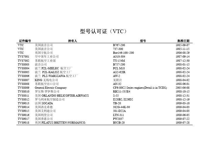
型号认可证(VTC)证件编号持有人型号批准日期VTC 美国波音公司B767-2001985-09-07 VTC 美国波音公司737-3001985-11-15 VTC 英国宇航公司Bae146-100/-2001986-08-29 TV87001 空中客车工业公司A310-3041987-09-14 TV87002 苏联航空工业部TY-154M1987-12-30 TV88003 波音公司B757-2001988-01-15 TV88004 波兰PZL-MIELEC 航空工厂PCL M181988-02-24 TV88005 波兰 PZL-KALISZ航空工厂AS2-62IR1988-02-24 TV88006 波兰 PLZ-WARSZAWA航空工厂AW-21988-02-24 TV88007KING无线电公司见附注1988-04-02 TV88008 苏联航空出口公司AN-321988-06-01 TV88009 General Electric Company CF6-80C2 Series engines(Detail is in TCDS) 2005-06-08 TV88010 罗尔斯·罗伊斯公司RB211-535E41988-10-15 TV88011 美国ORLANDO HELICOPTER AIRWAYS S-55 1988-12-31 TV88012 罗马利亚航空制造公司IS28B2,IS29D21988-12-19 TV89013 法国SOCATA TB-201989-03-10 TV89014 美国洛克希德382G-44K-301989-04-03 TV89015 美国艾利逊公司501-D22A1989-04-03 TV89016 美国利登公司LTN-3111989-06-05 TV89017 美国普惠公司PW20371989-07-22 TV89018 英国PILATUS BRITTEN-NORMANCO. BN2B-20 1989-07-28证件编号持有人型号批准日期TV89019 联合技术公司普惠民用产品分公司PW4052,40561989-09-05 TV89020 加拿大普惠公司PT6A-27,-61,PW1231989-12-01 TV90022 空中客车工业公司A300-600R1990-08-25 TV90023 苏联速度机械厂YAK-421991-02-12 TV91024 波音飞机公司B737-5001991-04-12 TVC001A 法宇航AS350B1/B21991-05-23 VTC002A 美国麦道公司MD-111991-05-23 VTC003A 美国波音公司B747-2J6F1991-06-03 VTC004A 美国麦道公司MD-11F1991-10-17 VTC005A 萨伯-斯堪尼亚公司SAAB340A/B1992-03-09 VTC006A 德哈韦兰公司DHC-8-3001992-04-08 VTC007E 美通用电气公司CT7-5A2/-9B1992-05-10 VTC008A 美国波音公司767-3001992-06-02 VTC009A 荷兰福克公司F28MARK01001992-08-21 VTC010E 英国罗罗公司TAY650-151992-09-04 VTC011A 美国派泊公司PA-42-7201993-01-04 VTC012A 瑞典萨伯公司SAAB340A/B1993-02-23 VTC013A 英国宇航公司Bae146-3001993-03-02 VTC014E 美国大陆公司TSIO-550-B1993-03-18 VTC015A 美国赛斯纳公司CESSNA208/208B1993-04-05Div.3GFR34C703/1106GA1993-05-12 AccessoryVTC016P McCauleyVTC017E 美国盖瑞特公司TFE731-3B/-3BR1993-05-12 VTC018A 吉斯兰公司GA2001993-05-18 VTC019A 美国赛斯纳公司650(CITATION VI)1993-06-07 VTC020E 美国莱康明公司ALF502R5/LF507-1H1993-07-31证件编号持有人型号批准日期VTC021A 美国雷克公司LAKE-2501993-08-23 VTC022A 乌兰.乌德航空工厂/米里设计局MI-8T1993-10-22 VTC023E 美国普惠公司JT8D-17A,JT8D-217A/C1993-12-25 VTC024E 美国普惠公司PW4158,44601994-02-242005-08-19 VTC025E LycomingEngines IO-540-K1B5/-C4D5D/-C4D5/-C4B5/-V4A5/-AE1A5VTC026A 美国麦道公司DC-9-821994-03-10 VTC027E 美国莱康明公司TIO-540-AA1AD1994-03-18 VTC028E 美国莱康明公司O-540-E4C51994-03-18 VTC029E 美国莱康明公司IO-720-D1B1994-03-18 VTC030E 美国莱康明公司O-235-N2A/-N2C1994-03-18 VTC031A 因斯特龙直升机公司F28F,280FX,TH-28,4801994-04-20 VTC032A 法国苏柯达工厂TB2001994-04-25 VTC033A 美国仙童公司SA227-DC1994-09-20 VTC034A RAYTHEENCOMPANY B300/300CSUPER KING AIR1995-04-22 AIRCRAFTVTC035E PRATT&WHITNEY CANADA INC. PT6T-3 1995-06-02 VTC036E PRATT&WHITNEY CANADA INC.PT6A-114/114A/42/60A/65R1995-06-02 VTC037E PRATT&WHITNEY CANADA INC. PW127C 1995-06-02 INDUSTRIE A320-111/-211/-212/-231/-232 /-214 1997-07-10 VTC038A AIRBUSVTC039A LEARJET INC. LEARJET 55 1995-08-10 VTC040E PRATT & WHITNEY CANADA INC. PT6T-3B 1995-10-16 INC.TPE331-12UHR1995-10-23 VTC041E ALLIEDSIGNALVTC042P Hamilton Standard Division 247F-3 1995-11-07 VTC043P Hamilton Standard Division14SF-5/14SF-11/14SF-151995-11-07 VTC044E Textron Lycoming Reciprocating Engine Division IO-540-C4B5D 1995-11-09证件编号持有人型号批准日期VTC045E Textron Lycoming Reciprocating Engine Division IO-360-A1B6 1995-11-09VTC046E Textron Lycoming Reciprocating Engine Division IO-720-D1BD 1995-11-09VTC047E Textron Lycoming Reciprocating Engine Division O-540-F1B5 1995-11-09VTC048E Textron Lycoming Reciprocating Engine Division HIO-360-F1AD 1995-11-09VTC049E Textron Lycoming Reciprocating Engine Division O-540-H2A5 1995-11-09VTC050E Textron Lycoming Reciprocating Engine Division O-540-A1D5 1995-11-091995-11-07VTC051E International Aero Engines AG(IAE) V2527-A5,V2530-A5,V2525-D5,V2528-D5 VTC052E International Aero Engines AG(IAE) V2500-A1 1995-11-07VTC053A BoeingAirplane Group B777-200 1995-12-26 CommercialVTC054E General Electric Company GE90-76B/-85B 1995-12-26Airplane Group B737-400 1995-12-21VTC055A BoeingCommercialHelicopter Company R44 1996-01-04VTC056A RobinsonPlc.RB211-524H-361996-04-25VTC057E Rolls-RoyceVTC058A Airbus A340-211,-311,-212,-312,-213,-313,-6422003-04-21VTC059A Robinson Helicopter Company R22 Beta , R22 Mariner 1996-07-17Corporation MD-90-301996-07-22VTC060A McDonnellDouglasInc.Learjet601996-07-26VTC061A Learjet1996-09-19VTC062A AEROSPATIALE (on behalf of AEROSPATIAL&ALENIA) ATR42-300/320,ATR72-102/202/212/101/201/211WHITNEYCANADA INC. PW120/121/124B/127 1996-09-19 &VTC063E PRATTVTC064E CFM International, S.A. Detail is in TCDS NO.VTC064E 2005-08-17VTC065E General Electric Company, Aircraft Engine Group GE90-77B/-90B/-92B1997-01-06VTC066E General Electric Company, Aircraft Engine Group CF6-80E1A1/-80E1A21997-02-032005-02-04VTC067A Airbus A330-201 A330-301 A330-243 A330-343A330-321 A330-322 A330-341 A330-342证件编号持有人型号批准日期CanadaWhitneyInc. PW305, PW305A, PW305B 1997-03-18&VTC068E Pratt50 1997-05-28A VIATION MYSTERE-FALCONVTC069A DASSAULTPTY. LTD. DRIFTER SB-582 1997-08-12VTC070A AUSTFLIGHTU.L.A.VTC071A The Boeing Company 747-400, 747-400F 2002-08-30ALENIA & AERO.) ATR72-212A 1997-08-19VTC072A AEROSPATIALE(ONOFBEHALFVTC073A Cessna Aircraft Company Model 525 1997-11-12Company Cessna5252005-04-01AircraftVTC073A CessnaCorporation S-76C with Arriel 2S1 Engines 1998-01-24AircraftVTC074A SikorskyVTC075E Pratt & Whitney Division United Technologies Co. PW4164,PW4168/PW4090;PW4077D;PW4084D1998-02-23Company172R1998-04-27VTC076A CessnaAircraftVTC077E CFM International, S.A. CFM56-7B series1998-05-03(CFM56-7B18, -7B20,-7B22,-7B24,-7B26,7B27)VTC078E Pratt & Whitney Canada Inc. PW-127F 1998-05-04VTC079P Hamilton Standard Division, United Technologies Corporation568F-1 1998-05-14VTC080A BellTextron Bell206B/206L-4/4071998-05-25 HelicopterVTC081A Mil Moscow Helicopter Plant Public Company Mi-171/Mi-171A 1998-07-22CommercialAirplane Group 737-700/-800 1998-06-10VTC082A BoeingVTC083A Robinson Helicopter Company R22 Beta, R22 Mariner 1998-09-15VTC084A Robinson Helicopter Company R44, R44 II 2004-11-03VTC085A AirbusIndustrie A321-111 /-112 /-131 /-211 /-231 1998-09-15VTC086A Brantly International Inc. B-2B 1998-12-07VTC087A EUROCOPTER AS332L1/ASS332L1998-12-15VTC088A RaytheonCompany Hawker800XP1999-04-28AircraftVTC089A Raytheon Aircraft Company Beechjet 400A 1999-05-31Corporation TV3-117VM,TV3-117VMSeries 2 1999-07-14VTC090E Klimov证件编号持有人型号批准日期Company1900D1999-10-15 AircraftVTC091A Raytheon5001999-12-17 Enterprises,Inc GTVTC092A QuicksilverVTC093A Dornier Luftfahrt GmbH Dornier 328-300 2000-01-312000-03-15VTC094E. Allison Engine Company 250-C20R/2、-C20J,C20W,B17F,C30,C30P,C30S2000-03-15 Propeller HC-B4MP-3C/M10476K,VTC095P. HartzellHC-E3YR-1RLF/FL7663D-2Q,HC-C2YK-1BF/F8477-4,HC-C2YK-2CUF/FC8477-4,HC-C3YR-1RF/F8475R,HC-B3TN-3B/T10173B-3,HC-B3TN-3K/T10173AB-6QVTC096A. Polskie Zaklady Lotnicze Co.Ltd., Poland M18B DROMADER 2000-07-12VTC097A.Bell Helicopter Textron Canada Bell Model 427 2000-04-292000-07-05VTC098E.Rolls-RoyceCorporation AE3007C,AE3007A,AE3007A1/1,AE3007A1/2,AE3007A1,AE3007A1/3,AE3007A1P,AE3007A3Industrie A319-111/-112/-113/-114/-115/-131/-132/-1332000-07-05VTC099A AirbusVTC100E Pratt & Whitney Canada Inc. JT15D-5 2000-07-20Canada Inc. PW530A 2000-07-20 WhitneyVTC101E Pratt&WhitneyCanada Inc. PW545A 2000-07-20 &VTC102E PrattCanada Inc. PW306A,PW306B 2000-07-20 Whitney&VTC103E Pratt2000-07-20VTC104E Pratt & Whitney Canada Inc.PW206A/206B/206C/206D/206E/207DInc.PW127J/118/118A/118B2000-07-20CanadaWhitneyVTC105E Pratt&VTC106P Hartzell Propeller Inc. HC-E4A-3J/E10950PB;HD-E6C-3B/E13890K2000-07-20证件编号持有人型号批准日期Lnc.DHC-8-4002000-08-16 VTC107A BombarierVTC108A MD HELICOPTERS INC MD600N 2000-09-13 AEROSPACE CL-600-2B192000-09-30 VTC109A BOMBARDIEREngines CF34-3A1/-3B/-3B12000-10-11 AircraftElectricVTC110E GeneralVTC111E Pratt & Whitney Canada Inc. PW150A 2000-10-26 VTC112A EurocopterDeutschland(ECD)EC135P1/T1/P22000-11-09Deutschland(ECD)EC135P1/T1/P2/T22005-01-31 VTC112A EurocopterVTC113A EMBRAER EMB-145ER/LR2000-11-29 VTC114A EUROCOPTER EC120B2001-05-21 VTC115A The New Piper Aircraft, Inc. PA-44-180 2001-05-27 Company560XL2001-05-27 AircraftVTC116A CessnaEngines V2522-A5,V2524-A5,V2527M-A5,V2533-A52001-06-08 AeroVTC117E InternationalAircraftCompany CESSNA7502001-07-26 CessnaVTC118A TheSpA A109E,A1192006-04-30 VTC119A AgustaInc.CL-600-2B16(604 Variant) 2002-03-04 VTC120A BombardierPZL-104WILGA 80, PZL-104M WILGA 2000 2002-03-29 VTC121A PANSTWOWE ZAKEADY LOTNICZE “Warszawa-Okecie”S.A2002-03-29 VTC122E ALLIEDSIGNALINC.TFE731-3/-3R,-3A/-3AR,-3C/-3CR,-3D/-3DR,-5B/-5BRVTC123E TURBOMECA ARRIEL-1S1/-1D1/-2S1/-2B/-2C/-2C1/-2B12002-03-29 VTC124A Schweizer Aircraft Corporation Model 269C-1、269C、269D Configuration A 2005-02-06 VTC125E TURBOMECA MAKILA 1A/1A1/1A2 Engine 2002-04-15 VTC126A The Boeing Company B737-600 2002-04-29 VTC127A EUROCOPTER EC155B,EC155B12005-08-05 Helicopters Inc. MD 900 2002-06-28 VTC128A MD证件编号持有人型号批准日期VTC129E WSK PZL, Kalisz SA Engine AI-14RA and AI-14RC 2002-07-25 VTC130A Cessna Aircraft Commany Cessna 172S 2002-07-26 AircraftCommany Cessna182T/T182T2002-07-26 VTC131A CessnaVTC132A Cessna Aircraft Commany Cessna 206H/T206H 2002-07-26 Whitney PW4062A2002-08-15 VTC133E PrattandINC OE600A2002-08-30 VTC134E ORENDARECIPL.P Gulfstream2002002-09-10 AerospaceVTC135A GulfstreamContinental Motors, Inc. IO-240-B 2003-01-10 VTC136E TeledyneVTC137P EADS-PZL“Warszawa-okecie” S.A. US-122000 2003-01-31 VTC138A SOCATA-Aerospatiale Matra TB9/TB10 2003-04-212003-05-13 VTC139E Bombardier-Rotax GmbH & Co. KG Rotax Engine Type 912A/F/S (Series)、914F(Series)VTC140E Rolls-Royce plc. RB211 Trent 553-61, 556-61, 560-61 and2003-05-13556B-61Engine2003-05-13 VTC141E Rolls-Royce plc.RB211-535E4-B-75 and RB211-535E4-B-37EngineIV2003-09-15 VTC142A GulfstreamCorporation GulfstreamAerospace2003-10-09 VTC143E General Electric Aircraft Engines CF34-8C1/-8C5/-8C5A1/-8C5B1/-8C5A2/-8C5A3/-8E2/-8E2A1/-8E5/-8E5A1/-8E5A2/-8E6/-8E6A1 EngineInc.CL-600-2C10(Regional Jet Series 700 and 701) 2003-10-21 VTC144A BombardierVTC145E Rolls-Royce Deutschland Ltd and Co KG Tay611-8 Engine 2003-10-28 VTC146A Raytheon Aircraft Company Model 390 (Premier I ) 2003-11-02Inc.PW207E,PW206B2,PT6A-135A2003-01-31 CanadaWhitneyVTC147E PrattandVTC148E Williams International FJ44-1A,-2A Engines 2003-12-11证件编号持有人型号批准日期VTC149E Lycoming Engines, An Operating Division of A VCOHIO-360-D1A/G1A2004-06-18 CorporationIndustries DA20-C12004-07-27 VTC150A DiamondAircraftEntwicklung GMBH MTV-7 2004-08-24 VTC151P MT-Propeller2004-08-24 LYCOMING(L)O-360-A1H6, IO-360-L2A, IO-540-AB1A5,VTC152E TEXTRONIO-540-AC1A5, TIO-540-AJ1A, TIO-540-AK1AVTC153P Hoffmann GmbH & Co KG HO-V 62 ()() Series Propeller 2004-08-25 VTC154A DiamondAircraft DA40/DA40D2004-10-26Inc.Learjet452004-12-27 VTC155A LearjetVTC156P Hartzell Propeller Inc.HC-C2YR-1BF/F7495S2005-01-04 VTC157E Rolls-Royce plc RB211 Trent 768-60, 772-60, 772B-60 2005-02-03 VTC158E Thielert Aircraft Engines GmbH TAE125-01 2005-02-03 EntwicklungGmbH MT-6(),MT-12()2005-02-03 VTC159P MT-PropellerVTC160E Pratt and Whitney Canada Inc. PW545B 2005-03-04 VTC161A American Blimp Corporation A-60+ 2005-04-12 AircraftCompany C90A2005-04-30 VTC162A RaytheonEntwicklung GmbH MT Fixed Pitch,MT( )( )( )-( )( ) 2005-04-30 VTC163P MT-PropellerInc.TFE731-20/-20AR/-20BR/-20R/-40/-40R/-602006-05-19 VTC164E HoneywellInternationalVTC165E General Electric Company CF6-50E2 2005-08-17 VTC166A DiamondIndustries GmbH Diamond DA 42 2005-06-03 AircraftCompany B737-9002005-06-10 VTC167A BoeingVTC168P Sensenich Propeller Manufacturing Co., INC 76EM SEIRES PROPELLER 2005-06-24 VTC169A TigerLLC AG-5B2005-07-08 AircraftEngines O-360-A4K2005-8-19 VTC170E LycomingVTC171E Pratt & Whitney Canada Corp. PT6A-21 2006-05-19证件编号持有人型号批准日期VTC172E Pratt & Whitney Canada Corp. PT6B-37A 2006-05-19 Aircraft Company BE-103 2005-12-22 VTC173A BerievVTC174A Cirrus Design Corporation SR20,SR222005-12-31。
10GXE01 10GX 类别 6A 增强网线,4对,F FTP,LSZH 室内 CPR Eca说明

Product:10GXE0110GX Category 6A Enhanced Cable, 4 Pair, F/FTP, LSZH Indoor CPR EcaProduct DescriptionCategory 6A Enhanced Premise Horizontal Cable (625MHz), 4-Pair, 23 AWG Solid Bare Copper conductors, F/FTP, Foam Polyethylene insulation, each pair with Beldfoil® shield, AWG 26 solid tinned copper drainwire, overall Beldfoil® shield, LSZH jacket, CPR Euroclass EcaTechnical SpecificationsProduct OverviewConstruction DetailsConductorInsulationCable CoreInner ShieldOuter ShieldOuter JacketElectrical CharacteristicsElectricalsDelay45 ns/100m77% High FrequencyFrequency[MHz]Max. Insertion Loss(Attenuation)Min.NEXT[dB]Min.PSNEXT[dB]Min.ACR[dB]Min.PSACR[dB]Min. ACRF(ELFEXT) [dB]Min. PSACRF(PSELFEXT) [dB]Min. RL(Return Loss)[dB]Min.PSANEXT[dB]Min.PSAACRF[dB]Min.TCL[dB]Min.ELTCTL[dB]1 2.1 dB/100m75.372.373.270.268652067674035 4 3.8 dB/100m66.363.362.559.55653236766.23423 10 5.9 dB/100m60.357.354.451.44845256758.23015 167.5 dB/100m57.254.249.846.843.940.9256754.12810.9 31.210.5 dB/100m52.949.942.439.438.135.123.66748.325.1 5.1 62.515 dB/100m48.445.433.430.432.129.121.565.642.32210019.1 dB/100m45.342.326.223.2282520.162.538.22012521.5 dB/100m43.840.822.319.326.123.119.46136.31920027.6 dB/100m40.837.813.210.22219185832.21725031.1 dB/100m39.336.38.3 5.3201717.356.530.21630034.3 dB/100m38.135.1 3.90.918.515.517.355.328.750045.3 dB/100m34.831.8-10.4-13.4141117.35224.262551.2 dB/100m33.430.4-17.8-20.812.19.117.350.622.3Table Notes:Limits below 4 MHz and at 625 MHz are for information only. Reference standard: IEC 61156-5Transfer ImpedanceFrequency Max. Transfer Impedance1 Mhz Max. 50 mOhm/m10 Mhz Max. 100 mOhm/m30 Mhz Max. 200 mOhm/m100 Mhz Max. 1000 mOhm/mTransfer Impedance Class:Grade 2Screening Class:Type IbTable Notes:Coupling AttenuationVoltageVoltage Rating72 V DCMechanical CharacteristicsTemperatureOperating Installation-30°C to +60°C0°C To +50°CBend RadiusStationary Min.Installation Min.29 mm (1.1 in)57 mmMax. Pull Tension:79 N (18 lbf)Bulk Cable Weight:48 kg/kmStandards and ComplianceEnvironmental Suitability:Indoor - Euroclass EcaFlammability / Reaction to Fire:IEC 60332-1-2CPR Compliance:CPR Euroclass: Eca; CPR UKCA Class: EcaIEEE Compliance:PoE: IEEE 802.3bt Type 1, Type 2, Type 3, Type 4Data Category:Category 6ATIA/EIA Compliance:ANSI/TIA 568.2-DISO/IEC Compliance:ISO/IEC 11801-1, IEC 61034-2 - Smoke Density Min Transmittance = 60%CENELEC Compliance:EN 50173-1, Segregation class according EN50174-2 = dEuropean Halogen Free Standards:IEC 62821-1 Halogen Free Compliance = Yes, IEC 60754-1 - Halogen Amount = Zero, IEC 60754-2 - Halogen Acid Gas Amount - Max. Conductivity = 2.5 µS/mm, IEC 60754-2 - Halogen Acid Gas Amount - Min. pH = 4.3European DirectiveCompliance:EU CE Mark UK Regulation Compliance:UKCA Mark Product NotesNotes:Electrical values are expected performance based on cable testing and representative performance within a typical Belden system.HistoryUpdate and Revision:Revision Number: 0.324 Revision Date: 12-12-2023Part NumbersVariantsItem #Color Putup Type Length EAN10GXE01.06500Blue Reel500 m871960500034710GXE01.08500Gray Reel500 m871960500036110GXE01.K8500Gray Reel500 m871960518886110GXE01.07500Purple Reel500 m871960500035410GXE01.09305White Reel305 m8719605000378© 2023 Belden, IncAll Rights Reserved.Although Belden makes every reasonable effort to ensure their accuracy at the time of this publication, information and specifications described here in are subject to error or omission and to change without notice, and the listing of such information and specifications does not ensure product availability.Belden provides the information and specifications herein on an "ASIS" basis, with no representations or warranties, whether express, statutory or implied. In no event will Belden be liable for any damages (including consequential, indirect, incidental, special, punitive, or exemplary damages) whatsoever, even if Belden has been advised of the possibility of such damages, whether in an action under contract, negligence or any other theory, arising out of or in connection with the use, or inability to use, the information or specifications described herein.All sales of Belden products are subject to Belden's standard terms and conditions of sale.Belden believes this product to be in compliance with all applicable environmental programs as listed in the data sheet. The information provided is correct to the best of Belden's knowledge, information and belief at the date of its publication. This information is designed only as a general guide for the safe handling, storage, and any other operation of the product itself or the one that it becomes a part of. The Product Disclosure is not to be considered a warranty or quality specification. Regulatory information is for guidance purposes only. Product users are responsible for determining the applicability of legislation and regulations based on their individual usage of the product.。
Eaton Moeller CI-K 219654 Insulated Enclosure 说明书
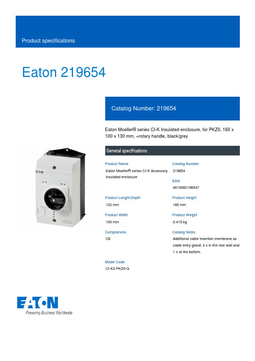
Eaton 219654Eaton Moeller® series CI-K Insulated enclosure, for PKZ0, 160 x 100 x 130 mm, +rotary handle, black/greyGeneral specificationsEaton Moeller® series CI-K Accessory Insulated enclosure2196544015082196547132 mm 180 mm 100 mm 0.415 kg CEAdditional cable insertion membrane as cable entry gland: 2 x in the rear wall and 1 x at the bottom.CI-K2-PKZ0-GProduct NameCatalog Number EANProduct Length/Depth Product Height Product Width Product Weight Compliances Catalog NotesModel CodePlasticBlack-gray rotary knobN and PE terminal2 x M25 (cable entry knockout at the bottom) 2 x M25 (cable entry knockout at the top)IP65NEMA OtherSurface mountingAccessories+L-PKZ0 (2 units), +NHI or AGM, +U or A, PKZM0-…-25 °C 70 °C 0 W12.5 W0 W0 A0 WMeets the product standard's requirements.Meets the product standard's requirements.Meets the product standard's requirements.Meets the product standard's requirements.Please enquireDoes not apply, since the entire switchgear needs to be evaluated.Enclosure material Fitted with: Knockouts Degree of protection ModelProduct category Used withAmbient operating temperature - min Ambient operating temperature - max Equipment heat dissipation, current-dependent PvidHeat dissipation capacity PdissHeat dissipation per pole, current-dependent PvidRated operational current for specified heat dissipation (In) Static heat dissipation, non-current-dependent Pvs10.2.2 Corrosion resistance10.2.3.1 Verification of thermal stability of enclosures10.2.3.2 Verification of resistance of insulating materials to normal heat10.2.3.3 Resist. of insul. mat. to abnormal heat/fire by internal elect. effects10.2.4 Resistance to ultra-violet (UV) radiation10.2.5 LiftingDoes not apply, since the entire switchgear needs to be evaluated.Meets the product standard's requirements.Does not apply, since the entire switchgear needs to be evaluated.Meets the product standard's requirements.Does not apply, since the entire switchgear needs to be evaluated.Does not apply, since the entire switchgear needs to be evaluated.Is the panel builder's responsibility.Is the panel builder's responsibility.Is the panel builder's responsibility.Is the panel builder's responsibility.Is the panel builder's responsibility.The panel builder is responsible for the temperature rise calculation. Eaton will provide heat dissipation data for the devices.Is the panel builder's responsibility. The specifications for the switchgear must be observed.Is the panel builder's responsibility. The specifications for the switchgear must be observed.The device meets the requirements, provided the information in the instruction leaflet (IL) is observed.Brochure - CI-K small enclosuresCE CI..-PKZ.. Surface mounted enclosures and accessories PKZ UKCA CI..-PKZ.. Surface mounted enclosures and accessories PKZeaton-manual-motor-starters-enclosure-ci-k-accessory-dimensions-003.epseaton-manual-motor-starters-enclosure-ci-k-accessory-dimensions.eps eaton-manual-motor-starters-enclosure-ci-k-accessory-dimensions-002.epseaton-manual-motor-starters-enclosure-ci-k-accessory-3d-drawing-003.epsETN.CI-K2-PKZ0-Geaton-manual-motor-starters-ci-k2-k4-pkz-instruction-leaflet-il03402002z.pdfDA-CD-ci_k2_pkz0_gDA-CS-ci_k2_pkz0_g10.2.6 Mechanical impact10.2.7 Inscriptions10.3 Degree of protection of assemblies10.4 Clearances and creepage distances10.5 Protection against electric shock10.6 Incorporation of switching devices and components 10.7 Internal electrical circuits and connections10.8 Connections for external conductors10.9.2 Power-frequency electric strength10.9.3 Impulse withstand voltage10.9.4 Testing of enclosures made of insulating material 10.10 Temperature rise10.11 Short-circuit rating10.12 Electromagnetic compatibility10.13 Mechanical function Brochures Compliance information DrawingseCAD model Installation instructions mCAD modelEaton Corporation plc Eaton House30 Pembroke Road Dublin 4, Ireland © 2023 Eaton. All rights reserved. Eaton is a registered trademark.All other trademarks areproperty of their respectiveowners./socialmedia。
ATA-2161 高压放大器商品说明书
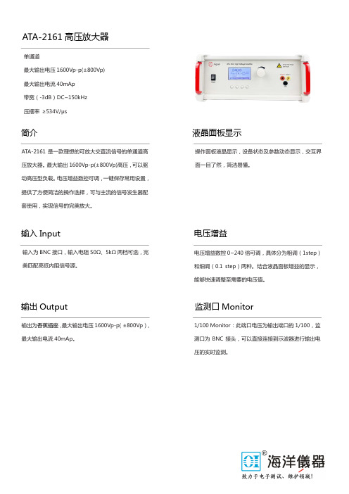
简介 液晶面板显示输入Input 电压增益输出Output 监测口MonitorATA-2161高压放大器单通道最大输出电压1600Vp-p(±800Vp) 最大输出电流40mAp 带宽(-3dB )DC~150kHz 压摆率 ≥534V/μsATA-2161是一款理想的可放大交直流信号的单通道高压放大器。
最大输出1600Vp-p(±800Vp)高压,可以驱动高压型负载。
电压增益数控可调,一键保存常用设置,提供了方便简洁的操作选择,可与主流的信号发生器配套使用,实现信号的完美放大。
操作面板液晶显示,设备状态及参数动态显示,交互界面一目了然,简洁易懂。
电压增益数控0~240倍可调,具体分为粗调(1step)和细调(0.1 step)两种。
结合液晶面板增益的显示,能够快速调整至需要的电压值。
输入为BNC 接口,输入电阻50Ω、5kΩ两档可选,完美匹配高低内阻信号源。
输出为香蕉插座,最大输出电压1600Vp-p (±800Vp ),最大输出电流40mAp 。
1/100 Monitor :此端口电压为输出端口的1/100,监测口为BNC 接头,可以直接连接到示波器进行输出电压的实时监测。
规格参数 其他订货信息供电电压: AC 220V±10%,50Hz 工作温度: 0°C ~ 45°C 存储温度: -20°C ~ 50°C 工作湿度: ≤80% RH ,无冷凝 质保: 3 年尺寸:365*163*365mm (宽*高*深)型号 ATA-2161 通道数 1 输出形式 差分输出 带宽(-3dB ) DC~150kHz 最大输出电压1600Vp-p (±800Vp ) 最大输出电流20mAp (DC~50Hz )40mAp (>50Hz )最大输出功率32Wp 保险丝 2A/250V电压增益x0~240(0.1 step/1 step) 负载R L 上限≥39.8k Ω(DC~50Hz )≥19.8k Ω(>50Hz )输出电阻 200Ω /10k Ω(可定制)输入电阻 50Ω / 5k Ω 输入幅度 0~10Vp-pMAX 输出电压误差 ≤±3%FS@1kHz 电压监测 100:1(±5%) 压摆率 ≥534V/μs谐波失真(THD ) ≤0.1%@1kHz ,100Vp-p输出电压零点漂移≤±0.3V 信噪比 ≥80dB 输出接口 4mm 香蕉插座 保护 过流保护 信号地与机壳、电源线地相连型号: ATA-2161指标描述:DC~150kHz (-3dB) 单通道高压放大器 附件:三芯电源线*1根,BNC 线*2根,输出线*1套,保险管*1只,产品说明书、合格证、装箱清单、出厂测试报告各1份。
- 1、下载文档前请自行甄别文档内容的完整性,平台不提供额外的编辑、内容补充、找答案等附加服务。
- 2、"仅部分预览"的文档,不可在线预览部分如存在完整性等问题,可反馈申请退款(可完整预览的文档不适用该条件!)。
- 3、如文档侵犯您的权益,请联系客服反馈,我们会尽快为您处理(人工客服工作时间:9:00-18:30)。
HAT2196C
Silicon N Channel MOS FET
Power Switching
REJ03G1235-0500
Rev.5.00
Jun. 13, 2005
Features
• Low on-resistance
R DS(on) = 45 mΩ typ. (at V GS = 4.5 V)
• Low drive current.
• High density mounting
• 2.5 V gate drive devices.
Outline
Absolute Maximum Ratings
(Ta = 25°C)
Unit
Ratings
Item Symbol
Drain to source voltage V DSS 20 V
Gate to source voltage V GSS ±12 V
Drain current I D 2.5 A
Drain peak current I D (pulse)Note1 10 A
Body - Drain diode reverse drain current I DR 2.5 A
Channel dissipation Pch Note 2 850 mW
Channel temperature Tch 150 °C
Storage temperature Tstg –55 to +150 °C
Notes 1. PW ≤ 10 µs, duty cycle ≤ 1%
2. When using the glass epoxy board. (FR4 40 × 40 × 1.6 mm)
Electrical Characteristics
(Ta = 25°C)
Item Symbol Min Typ Max Unit Test Conditions
Drain to Source breakdown voltage V (BR)DSS 20 — — V I D = 10 mA, V GS = 0 Gate to Source breakdown voltage V (BR)GSS ±12 — — V I G = ±10 µA, V DS = 0 Gate to Source leakage current I GSS — — ±10 µA V GS = ±10 V, V DS = 0 Drain to Source leakage current I DSS — — 1 µA V DS = 20 V, V GS = 0 Gate to Source cutoff voltage V GS(off) 0.4 — 1.4 V I D = 1 mA, V DS = 10 V — 45 58 m Ω I D = 1.3 A, V GS = 4.5 V Note3
Drain to Source on state resistance R DS(on) — 66 93 m Ω I D = 1.3 A, V GS = 2.5 V Note3
Forward transfer admittance | y fs | 4.5 7 — S I D = 1.3 A, V GS = 10 V Note3 Input capacitance Ciss — 270 — pF Output capacitance Coss — 85 — pF
Reverse transfer capacitance Crss — 35 — pF V GS = 0, f = 1 MHz,
V DS = 10 V Total gate charge Qg — 2.8 — nC Gate to Source charge Qgs — 0.6 — nC
Gate to Drain charge Qgd — 0.5 — nC V GS = 4.5 V, V DS = 10 V,
I D = 2.5 A Turn - on delay time t d(on) — 8 — ns Rise time t r — 19 — ns
Turn - off delay time t d(off) — 20 — ns Fall time
t f — 5 — ns V GS = 4.5 V, I D = 1.3 A,
V DD = 10 V, R L = 7.7 Ω , R g = 4.7 Ω Body - Drain diode forward voltage V DF — 0.8 1.1 V I F = 2.5 A, V GS = 0 Note3
Notes: 3. Pulse test
Main Characteristics
Package Dimensions
Ordering Information
Part Name Quantity Shipping Container HAT2196C-EL-E 3000
pcs Taping Note: For some grades, production may be terminated. Please contact the Renesas sales office to check the state of production before ordering the product.
RENESAS SALES OFFICES
Refer to "/en/network" for the latest and detailed information.
Renesas Technology America, Inc.
450 Holger Way, San Jose, CA 95134-1368, U.S.A
Tel: <1> (408) 382-7500, Fax: <1> (408) 382-7501
Renesas Technology Europe Limited
Dukes Meadow, Millboard Road, Bourne End, Buckinghamshire, SL8 5FH, U.K.
Tel: <44> (1628) 585-100, Fax: <44> (1628) 585-900
Renesas Technology Hong Kong Ltd.
7th Floor, North Tower, World Finance Centre, Harbour City, 1 Canton Road, Tsimshatsui, Kowloon, Hong Kong
Tel: <852> 2265-6688, Fax: <852> 2730-6071
Renesas Technology Taiwan Co., Ltd.
10th Floor, No.99, Fushing North Road, Taipei, Taiwan
Tel: <886> (2) 2715-2888, Fax: <886> (2) 2713-2999
Renesas Technology (Shanghai) Co., Ltd.
Unit2607 Ruijing Building, No.205 Maoming Road (S), Shanghai 200020, China
Tel: <86> (21) 6472-1001, Fax: <86> (21) 6415-2952
Renesas Technology Singapore Pte. Ltd.
1 Harbour Front Avenue, #06-10, Keppel Bay Tower, Singapore 098632
Tel: <65> 6213-0200, Fax: <65> 6278-8001。