manual_E-PGM+_usb_driver_setup
USB-4750_user_manual(CH)_ed.1USB模块用户使用手册
版权声明
随附本产品发行的文件为研华公司 2010 年版权所有,并保留相关权利。针对本手册中 相关产品的说明,研华公司保留随时变更的权利,恕不另行通知。 未经研华公司书面许可,本手册所有内容不得通过任何途径以任何形式复制、翻印、 翻译或者传输。本手册以提供正确、可靠的信息为出发点。但是研华公司对于本手册 的使用结果,或者因使用本手册而导致第三方权益受损,概不负责。
3.3
隔离数字量 I/O 连接.............................................20
3.3.1 数字量输入支持干 / 湿接点 ................................20
图 3.2: 隔离数字量输入连接............................20 3.3.2 隔离数字量输出连接 ......................................20
首先感谢您购买研华 USB-4750 数据采集模块。研华 USB-4750 数据采集模块功能强大, 适用于 USB 接口。该模块具有独特的电路设计和数据采集与控制的完整功能。
1.1
特性
USB-4750 具有如下测量与控制功能: 32 个隔离数字量输入 / 输出通道 所有通道的高电压隔离高达 2,500 VDC 支持干 / 湿接点 中断处理能力 隔离输出通道的高汇点电流 (最大 100 mA/ 通道 ) 热启动后仍保存数字量输出值 输出通道的初始状态可编程 板上接线端子
A.1
隔离数字量输入 ................................................ 24
表 A.1: 隔离数字量输入 ............................... 24
IBM v5000存储调试手册

2.1.3
主菜单界面 ............................................................................................................11
2.1.4
功能菜单详细选项 .................................................................................................11
2.2.4
创建卷 .................................................................................................................. 21
创建主机 .............................................................................................................. 23
2 磁阵始化操作 ..................................................................................................................... 1 2.1 基本设置 ................................................................................................................... 1
2.2.6
将卷映射到主机 ................................................................................................... 26
罗克韦尔 ControlLogix 系统 说明书

准备事宜 . . . . . . . . . . . . . . . . . . . . . . . . . . . . . . . . . . . . . . . . . . . . . . . . . . 19 1756-L7x 控制器部件. . . . . . . . . . . . . . . . . . . . . . . . . . . . . . . . . . . . . . 19
未随 1756-L6x 控制器提供的部件. . . . . . . . . . . . . . . . . . . . . . 33 1756-L6x 控制器安装. . . . . . . . . . . . . . . . . . . . . . . . . . . . . . . . . . . . . . 34 CF 卡的安装和取出 . . . . . . . . . . . . . . . . . . . . . . . . . . . . . . . . . . . . . . . 34 电池的连接与更换 . . . . . . . . . . . . . . . . . . . . . . . . . . . . . . . . . . . . . . . . 38 将控制器插入机架 . . . . . . . . . . . . . . . . . . . . . . . . . . . . . . . . . . . . . . . . 40 将控制器从机架拆下 . . . . . . . . . . . . . . . . . . . . . . . . . . . . . . . . . . . . . . 42
安装 1756-L7x 控制器 安装 1756-L6x 控制器
控制器使用入门
Intel USB4 评估坞站更新手册说明书

Intel USB4 Evaluation Dock Update ManualINFORMATION IN THIS DOCUMENT IS PROVIDED IN CONNECTION WITH INTEL® PRODUCTS. NO LICENSE, EXPRESS OR IMPLIED, BY ESTOPPEL OR OTHERWISE, TO ANY INTELLECTUAL PROPERTY RIGHTS IS GRANTED BY THIS DOCUMENT. EXCEPT AS PROVIDED IN INTEL'S TERMS AND CONDITIONS OF SALE FOR SUCH PRODUCTS, INTEL ASSUMES NO LIABILITY WHATSOEVER, AND INTEL DISCLAIMS ANY EXPRESS OR IMPLIED WARRANTY RELATING TO SALE AND/OR USE OF INTEL PRODUCTS, INCLUDING LIABILITY OR WARRANTIES RELATING TO FITNESS FOR A PARTICULAR PURPOSE, MERCHANTABILITY, OR INFRINGEMENT OF ANY PATENT, COPYRIGHT, OR OTHER INTELLECTUAL PROPERTY RIGHT.A "Mission Critical Application" is any application in which failure of the Intel Product could result, directly or indirectly, in personal injury or death. SHOULD YOU PURCHASE OR USE INTEL'S PRODUCTS FOR ANY SUCH MISSION CRITICAL APPLICATION, YOU SHALL INDEMNIFY AND HOLD INTEL AND ITS SUBSIDIARIES, SUBCONTRACTORS AND AFFILIATES, AND THE DIRECTORS, OFFICERS, AND EMPLOYEES OF EACH, HARMLESS AGAINST ALL CLAIMS COSTS, DAMAGES, AND EXPENSES AND REASONABLE ATTORNEYS' FEES ARISING OUT OF, DIRECTLY OR INDIRECTLY, ANY CLAIM OF PRODUCT LIABILITY, PERSONAL INJURY, OR DEATH ARISING IN ANY WAY OUT OF SUCH MISSION CRITICAL APPLICATION, WHETHER OR NOT INTEL OR ITS SUBCONTRACTOR WAS NEGLIGENT IN THE DESIGN, MANUFACTURE, OR WARNING OF THE INTEL PRODUCT OR ANY OF ITS PARTS.Intel may make changes to specifications and product descriptions at any time, without notice. Designers must not rely on the absence or characteristics of any features or instructions marked "reserved" or "undefined". Intel reserves these for future definition and shall have no responsibility whatsoever for conflicts or incompatibilities arising from future changes to them. The information here is subject to change without notice. Do not finalize a design with this information.The products described in this document may contain design defects or errors known as errata which may cause the product to deviate from published specifications. Current characterized errata are available on request. Contact your local Intel sales office or your distributor to obtain the latest specifications and before placing your product order. Copies of documents which have an order number and are referenced in this document, or other Intel literature, may be obtained by calling 1-800-548-4725, or goto: /design/literature.htm.All information provided related to future Intel products and plans is preliminary and subject to change at any time, without notice.Intel and the Intel logo are trademarks or registered trademarks of Intel Corporation or its subsidiaries in the United States and other countries.* Other names and brands may be claimed as the property of others.Copyright © 2020, Intel Corporation. All rights reserved.Important: Intel USB4 Evaluation Dock should be Powered off (No Power Supply must be Connected to the Board) when updating FW1.Equipment:1.1Dediprog SF600 (used to update the following components on the Intel USB4 EvaluationDock):Goshen Ridge: U8 – GR NVMDelta Bridge: UB10 – DB NVMUSB2.0 Hub: UB6 – USB2 HUB NVMFigure 1: Dediprog SF600SF600 SPI NOR Flash Programmer-Reference Link:https:///product/SF600-Link for downloading software:https:///download?productCategory=SPI+Flash+Solution&productName=SF600+SPI+NOR+Flash+Programmer&fileType=10Figure 2: Test ClipISP Testclip (SO8) (Compatible with SF100)Model Name: ISP-TC-8ISP Testclip (SO8) (Compatible with SF100)Reference Link: https:///product/ISP-TC-81.2Cypress MiniProg4 Program and Debug Kit CY8CKIT – 005 (used for updating thefollowing components):Cypress DMC (J5)Cypress CCG5(J4).Figure 3: Cypress MiniProg4 Program and Debug Kit CY8CKIT – 005-Reference Link: https:///product-detail/en/CY8CKIT-005/428-4713-ND/10314122?utm_medium=email&utm_source=oce&utm_campaign=3103_OCE20 RT&utm_content=productdetail_US&utm_cid=457843&so=64303907&mkt_tok=ey JpIjoiTURjNVlXVTBOekV4TW1aaSIsInQiOiJabjNuUjdzczgxZ0NCdWJBbExnR2k 3czkxNjhhZUVRcEFRdjlGSEZzeVZNNzdHcDRBSnEyYzhwa1F4QUJWS1NUeTJ wcEtXV1Z6d2tlbnpQbHUxamJCU1hqUHNhd3I4c1ZBaEd0WWtBUklLc0VsZ3F5T nc2eVRsYkZubXJrTm14dyJ9-Link for downloading software (Name of software: Download PSoC Programmer3.x.x.exe):https:///documentation/software-and-drivers/psoc-programmer-archiveNote: You need to create an account to able to download softwareNote: You need buy 5 Female to Male External Jumper for connecting.Figure 4: Female To Male Jumper-Reference Link: https:///GenBasic-Female-Solderless-Breadboard-Prototyping/dp/B077N7J6C4/ref=sr_1_7?dchild=1&keywords=male+to+female+jumper+wires&qid=1600894633&sr=8-7ponent Side and Back Side of Intel USB4 Evaluation DockFigure 5: Intel USB4 Evaluation Dock Component SideGR JTAG PA (UFP)DBR JTAGGR NVMCCG5 SWD Headers DMC SWD HeadersTMU CLKOUTFigure 6: Intel USB4 Evaluation Dock Back SideUB6 –USB2 HUB NVM UB10 – DB NVM Pin 0Pin 0Intel USB4 Evaluation Dock BKC File exampleGoshen Ridge: GR_4C_A0_rev9_ GATKES_BOARD.binDelta Bridge: DBR_CDR_ON_BOARD_rev1_NOSEC_sign.binFresco Hub: UB6_RegisterOnly_AddHeader_Merged_INTEL_1U5D_FL5801_1Q1_V02Cypress PD: DMC: CY7C65219‐40LQXIT_dmc_gatkex_creek_sha_3_3_0_1746_1_3_19_120W.hex CCG5: CYPD5235‐96BZXI_gatkex_3_3_1_39_2_8_0_nb.hex3.GoshenRidge FW UpdateExample file: GR_4C_A0_rev9_ GATKES_BOARD.bin-Step 1: Plug Dediprog SF600 flasher to PC-Step 2: Open Dediprog Engineering Application:o Go to Config Menu at the Top→Select Batch Operations(Top Left)→Check the Batch Operation Options is the same as Yellow Hightlight (see Figure 7) -→everything else leave as defaultFigure 7: Batch Operation Options- Step 3: Open U8 – NVM and take out the chip inside (see Figure 8)Figure 8: Chip inside U8 NVM- Step 4: Connect the SPI flash component to flasher (chip inside U8).Note: Make sure pin 0 of the chip is at the white line of the clip (see Figure 9)Figure 9: Connect the SPI Flash component to flasher (U8)- Step 5: Detect → choose First Chip number in the Memory list. (See Figure 10)- Note: If you do not see Memory list after Detect Chip → Please check the Connection between Chip and Test Clip-→Make sure they are connected correctlyPin 0Figure 10: Choose the chip from memory listNote: Majority of the time, the first component in the list is the correct chip.-Step 6: File load Goshen Ridge FW from BKC file bin file (See Figure 11), Select OKFigure 11: Load Intel USB4 Evaluation Dock bin file-Step 7: Batch-Step 8: Wait for all stages are PASS(see Figure 12), and Operation CompletelyFigure 12: All stages are PASSNote:-All stages are PASS only if you choose the correct chip in step 5.-In case you choose the wrong chip in step 5, you will see the following messageFigure 13: Error message after Batch when we choose the wrong chip Troubleshoot:-At Step 5: Detect → choose Second Chip number(W25Q168) of component in the list -Repeat Step 6 to Step 8-If Error:Programming Fail Message still occur→ At Step 5: Detect → choose Third Chip number (W25Q16CL)-Repeat Step 6 to Step 8-Step 9: Put the chip back to U8 GR NVM. Make sure pin 0 is on arrow position of U8 GR NVM .-Figure 14: Arrow Position of U8 GR NVM. Pin0 of Chip will go here4. Delta Bridge FW UpdateExample File: DBR_CDR_ON_BOARD_rev1_NOSEC_sign.bin Delta Bridge FW will be updated into UB10 componentFigure 15: Pin 0 at UB10While Dediprog SF600 flasher connected to PC and Dediprog application open:- Step 1: Connect the SPI flash component to flasher (UB10). Make sure the white linein the test clip connect to pin 0 (see Figure 16)Figure 16: Connect the SPI flash component to UB10-Step 2: Detect → choose First Chip number in the Memory list. (See Figure 17) -Note: If you do not see Memory list after Detect Chip→ Please check Connectionbetween Chip and Test Clip → Make sure they are connected correctlyFigure 17: Choose the chip from memory listNote: For most of the time, the first component in the list is a correct chip.-Step 3: File load Delta Bridge FW from BKC file bin file (See Figure 18)Figure 18: Load Intel USB4 Evaluation Dock bin file-NOTE:You may need to hold test clip to make sure test clip and chip connected. -Step 4: Batch-Step 5: Wait for all stages are PASS (see Figure 19) and Operation Completed.Figure 19: All stages are PASSNote:-All stages are PASS only if you choose the correct chip in step 2.-In the case you choose the wrong chip in step 2, you will see the following messageFigure 20: Error message after Batch when we choose the wrong chip-Troubleshoot:-At Step 3: Detect → choose Second Chip number (W25Q80) of component in the list -Repeat Step 3 to Step 5-If Error:Programming Fail Message still occur→ At Step 2: Detect → choose Third Chip number(W25Q80BL)-Repeat Step 3 to Step 55. Fresco Hub FW UpdateExample File:UB6_RegisterOnly_AddHeader_Merged_INTEL_1U5D_FL5801_1Q1_V02 Fresco Hub FW Update into UB6 componentFigure 21: Pin 0 at UB6While Dediprog SF600 flasher connected to PC and Dediprog application open:- Step 1: Connect the SPI flash component to flasher (UB6). Make sure the white line in the clip connect to bit 0.- Step 2: Detect → choose First Chip number in the Memory list. (See Figure 22) - Note: If you do not see Memory list after Detect Chip → Please check Connectionbetween Chip and Test Clip →Make sure they are connected correctlyFigure 22: Choose the chip from memory listNote: For most of the time, the first component in the list is the correct chip.-Step 3: File load Fresco USB Hub FW from BKC file bin file (See Figure 23)Figure 23: Load Intel USB4 Evaluation Dock bin file-NOTE:You may need to hold test clip to make sure test clip and chip connected. -Step 4: Batch-Step 5: Wait for all stages are PASS (see Figure 24), and Operation CompletelyFigure 24: All stages are PASSNote:-All stages are PASS only if you choose the correct chip in step 2.-In the case you choose the wrong chip in step 2, you will see the following messageFigure 25: Error message after Batch when we choose the wrong chip -Troubleshoot:-At Step 3: Detect → choose Second Chip number(W25Q168) of component in the list -Repeat Step 3 to Step 5-If Error: Programming Fail Message still occur→ At Step 2: Detect → choose Third Chip number(W25Q16CL)-Repeat Step 3 to Step 56. Cypress DMC FW UpdateExample DMC: CY7C65219‐40LQXIT_dmc_gatkex_creek_sha_3_3_0_1746_1_3_19_120W.hex Example CCG5: CYPD5235‐96BZXI_gatkex_3_3_1_39_2_8_0_nb.hex- Step 1: Plug Cypress MiniProg4 Program and Debug Kit CY8CKIT to the PC - Step 2: Connect MiniProg4 to DMC SWD connector (J5).Note: Only flash to the top five header pins of DMC SWD-- - - -Figure 26: DMC Headers (pin 6 to pin 10)-- Note: Make sure jumper connected to SWDIO pin of Cypress MiniProg4 connect toPin 10 at DMC header Cypress Minipro4 PinIntel USB4 Evaluation Dock DMCHeader PinSWDIO Pin 10 SWCLK Pin 9-CLK XRES Pin 8-XRES GND Pin 7-GND VTARG Pin 6-VDD-Step 3: Open Cypress PSOC programmerFigure 27: Cypress PSOC programmerNote: Make sure you see MiniProg4 in Port Selection-Step 4: Load file – DMC FW hex file (It may be inside PD folder from BKC file)Figure 28: Load file-Step 5: ProgramFigure 29: Select program on PSOC Programmer-Step 6: Wait until everything is PASSFigure 30: Wait until everything is PASSNote: If you see FAIL message, you may get the connection wrong between Cypress MiniProg4 and DMC header→ Check connection again at Step 2If connection between Cypress MiniProg4 and DMC header are correct but still get FAIL message→Close PSOC Programmer application and detach/attach MiniProg4 to host and reopen PSOC Programmer.7.Cypress CCG5 FW UpdateCCG5ABCCG5CDFigure 31: CCG5 SWD (J4) ConnectorWhile Cypress MiniProg4 Program and Debug Kit CY8CKIT connected to the PCand Cypress PSOC programmer open:Update CCG5 AB:-Step 1: Connect Cypress MiniProg4 to first CCG5 AB (J4) connectorCypress Minipro4 Pin Intel USB4 Evaluation Dock DMCHeader PinSWDIO Pin 10SWCLK Pin 9XRES Pin 8GND Pin 7VTARG Pin 6--Step 2: Load file – CCG5 FW hex file-Step 3: Program-Step 4: Wait until everything is PASSUpdate CCG5 CD:-Step 1: Connect Cypress MiniProg4 to first CCG5 CD (J4) connectorCypress Minipro4 Pin Intel USB4 Evaluation Dock DMCHeader PinSWDIO Pin 1SWCLK Pin 2XRES Pin 3GND Pin 4VTARG Pin 5-Step 2: Load file – CCG5 FW hex file (the same file for CCG5 AB update)-Step 3: Program-Step 4: Wait until everything is PASSNote: There is only 1 CCG5 file for CCG5 AB and CCG5 CDNote: If you see FAIL message, you may get connection wrong between CypressMiniProg4 and DMC header→ Check connection again at Step 1If connection between Cypress MiniProg4 and DMC header are correct but still get FAIL message→Close PSOC Programmer application and detach/attach MiniProg4 to host and reopen PSOC Programmer.-Step 5: Power Intel USB4 Evaluation Dock。
AnywhereUSB Gen 2 版本 3.99 Windows 驱动程序释放说明书

DIGI INTERNATIONAL9350 Excelsior Blvd, Suite 700Hopkins, MN 55343, USA+1 (952) 912-3444 | +1 (877) 912-3444AnywhereUSB Windows Driver Release NotesAnywhereUSB Gen 2Version 3.99 (December 04, 2019)INTRODUCTIONThis is a production release of the AnywhereUSB Generation 2 Windows Driver.SUPPORTED Products∙AnywhereUSB Gen 2 Windows Driver for 32-bit operating systems∙AnywhereUSB Gen 2 Windows Driver for 64-bit operating systemsSUPPORTED Operating Systems∙Windows 7∙Windows 8∙Windows 8.1∙Windows 10∙Server 2008-R2∙Server 2012∙Server 2012-R2∙Server 2016∙Server 2019KNOWN ISSUES∙The Belkin USB 2.0 4-port mobile-powered hub model F5U404BLK sometimes fails to enumerate when connected to AnywhereUSB.UPDATE BEST PRACTICESDigi recommends the following best practices:1.Uninstall the existing driver package via Add and Remove Hardware2.Install the new Windows driver package.TECHNICAL SUPPORTGet the help you need via our Technical Support team and online resources. Digi offers multiple support levels and professional services to meet your needs. All Digi customers have access to product documentation, firmware, drivers, and knowledge base and peer-to-peer support forums. Visit us at https:///support to find out more.CHANGE LOGVERSION 3.99 December 4, 2019NEW FEATURESNoneENHANCEMENTS1.AwUsbApi.dll is now multi-thread safe. This means that library functions can be calledconcurrently from different Windows threads.SECURITY FIXESNoneBUG FIXES1.With Windows 10 builds 1903 and 1908, the host computer would lose connectivity on reboot.This issue was determined to be due to the system network driver not being available at the time the AnywhereUSB system driver started. The “Digi AnywhereUSB Network Service” has been changed so that it works around this problem by disabling and re-enabling the “Network Attached USB Enumerator”. Note that this requires that the Startup Type of this service be configured for “Automatic” (which is the default).NOTE: The Microsoft-certified AnywhereUSB device drivers have not changed since v3.95 and will still show up with a version number of 3.95.2.AwUsbApi.dll AwUsbGetConnectionStatus function incorrectly reportedAWUSB_STATUS_IN_USE instead of AWUSB_STATUS_CONNECTED when the host itself was connected to an AnywhereUSB hub.VERSION 3.96 February 20191.The Windows Installer and the AnywhereUSB Configuration Utility are signed by DigiInternational to eliminate UAC (User Account Control) warning messages about unknown publisher.2.For customers using encrypted AnywhereUSB connections, the encryption service will nowuse certificates from either the Windows Local Machine Trusted Root CA store or theWindows Local Machine Intermediate CA store for authentication server certificates. In the previous 3.95 release, the encryption service only used the Trusted Root CA store.VERSION 3.95 April 20181.Several USB devices (e.g. Dediprog SF100 and Silicon Labs UART) fail to enumerate over ahigh latency WAN link. Fixed by setting ionhub service registry DWORD variableFastStartHub to 1. This variable is off (0) by default.[HKEY_LOCAL_MACHINE\SYSTEM\CurrentControlSet\services\ionhub]"FastStartHub"=dword:00000001(JIRA AWUSB-537)2.AnywhereUSB client driver awvusbd.sys blue-screens when connecting to an AnywhereUSBhub. Happens only with XenServer and XenCenter VM's. Fixed. (JIRA AWUSB-550)3.AnywhereUSB driver installer does not support upgrades. Installer now blocks attempts toupgrade over a previous installation. Previous installation must uninstalled first. You maybe prompted to reboot the computer. (JIRA AWUSB-438)ers can now import CA certificates to the Windows Certificate Store to authenticateserver certificates. The CA certificate must be installed on the "Local Computer" in theTrusted Root Certification Authorities store. (JIRA AWUSB-539)1.AwUsbGetConnectionStatus did not handle groups correctly. It also incorrectly reportedAWUSB_STATUS_IN_USE instead of AWUSB_STATUS_CONNECTED for host currentlyconnected to local machine. Fixed. JIRA AWUSB-492.2.On rare occasions the encryption service has stopped and forced users to restart it. It willnow automatically restart. (JIRA AWUSB-513)3.The encryption service now logs critical events which can be viewed from the WindowsEvent Viewer System log. (JIRA AWUSB-514)VERSION 3.91 September 20171.Client to hub connections with lengthy establishment times could lead to a blue screen ifprematurely disconnected by a user. Fixed. (JIRA AWUSB-421)2.Fixed memory leak in encryption service. (JIRA AWUSB-451)3.Disconnecting an AnywhereUSB hub connected to an Axis T8311 joystick caused a bluescreen. Fixed. (JIRA AWUSB-392)VERSION 3.90.223 June 20171.TLS v1.2 and SHA-2 (SHA-256) support. This only affects “Encrypted AnywhereUSB”.SHA-2 (SHA-256) certificates can now be used for authentication. Note that the certificatemust be signed using 2048-bit RSA encryption. Also, SHA-1 based certificates can still beused.Note:TLS v1.2 and SHA-2 support require AnywhereUSB firmware to be updated to at least rev N1(1.93). It still works with older firmware (starting with rev L v1.80) by "falling back" to TLS1.0.ers can specify a certificate "folder" instead of a certificate file when setting up"Encrypted AnywhereUSB" connections. You can specify it from the AnywhereUSBConfiguration Utility (AwUsbCfg.exe) or the console application (AwConsole.exe) just as you specify a file.Please note - to use a folder, each certificate must be renamed after the subject hash.Suppose you had a folder named c:\my-certs with two certificates - CertA.crt and CertB.crt.For example, to rename CertA.crt:a.Download an OpenSSL installer for Windows (version >= 1.0 since pre-1.0 versionsuse an older hash which will not work with AnywhereUSB).b.Open a command prompt from your certificate folder (c:\my-certs)c.Create a subject hash:c:\my-certs> openssl x509 -hash -in CertA.crt –nooutIt outputs an 8-digit hash (e.g. bc35a2e5)d.Rename (or copy) your certificate file with the hash as its base and the zerocharacter as its extension:c:\my-certs> copy CertA.crt bc35a2e5.0VERSION 3.90 January 20171.Support encryption in AnywhereUSB Programming API, AwUsbApi.dll.2.Workaround for Error Code 38. When all of the AnywhereUSB hubs are disconnected, thedevice manager unloads the ionhub.sys and awvusbd.sys drivers, and several outstanding references to the driver objects persist and block it from being removed from memory. Asubsequent attempt to connect to an AnywhereUSB hub will fail with an Error Code 38 and require a reboot in order to recover.To work-around this failure (most likely caused by intrusive third-party software) you must set these two variables to 1:[HKLM\System\CurrentControlSet\Services\AwVusbd]"DoNotUnload" = dword:1[HKLM\System\CurrentControlSet\Services\IonHub]"DoNotUnload" = dword:1Note: This work-around is disabled by default.VERSION 3.82 May 20161.Fix IOCTL Vulnerability - "Secunia advisory SA68000". (JIRA AWUSB-295)2.An unusually long network delay could lead to a BSOD. Fixed. (JIRA AWUSB-259)3.Fix Handle leak in Encryption Service. (JIRA AWUSB-310)VERSION 3.80 July 20151.Installer did not remove pre-InstallShield drivers (such as 3.60) and led to customercomplaints. Fixed.2.Configuration Utility was not remembering group assignment after disconnecting as it haddone in 3.60. Fixed.3.Added support in AwConsole for encrypted connections.VERSION 3.71 Jan 20151.OpenSSL encrypted USB traffic support (AES-128 encryption only). Firmware version 1.81and later is required.2.Optional "tunneling" of TCP connections over a single TCP connection between the hostand the AnywhereUSB remote hub to eliminate network disconnects due to inactivity. Note that tunneling is enabled automatically when data encryption is turned on. Firmwareversion 1.80 and later is required.3.New installer. Uninstalls will be done conventionally from Programs and Features insteadof from the Configuration Utility. However the configuration utility must be used touninstall an older version if you are upgrading. Note that the new installer copies the driver files to C:\Program Files\Digi\AnywhereUSB by default instead of c:\AnywhereUSB.4.The hub driver would sometimes unload with pending network I/O resulting in a bluescreen. Fixed.5.This release no longer supports signed drivers for Windows XP, Server 2003, and Server2008.VERSION 3.60 May 20141.Low and Full Speed devices which are attached to AnywhereUSB via an external USB2.0hub did not enumerate. Fixed. (JIRA AWUSB-77)2.AwUsbView did not show device speeds correctly. Fixed. (JIRA AWUSB-54)3.Add Multi-Host support to AwUsbApi DLL. (JIRA AWUSB-65)4.If a USB string contained zero as a character, AnywhereUSB would incorrectly treat it as aninvalid string. Fixed.5.Removed Reboot and Configure commands from AwConsole (the console configurationapp). (JIRA AWUSB-80)6.Added work-around for Microsoft Windows 8 / Server 2012 bug which kept USB MassStorages devices from working. (JIRA AWUSB-77)7.Fix bug with MultiTT (Multi Transaction Translator) external hub. (JIRA AWUSB-87)8.UnInstaller failed on Windows 8 because of a deprecated registry key. Fixed. (JIRA AWUSB-88)9.UnInstaller failed to bring up log in Windows 8 and Server 2012. Fixed. (JIRA AWUSB-88)10.When certain devices are removed, awvusbd.sys was causing a BSOD. Fixed. (JIRA AWUSB-86)11.Removed firmware and configuration app for legacy AnywhereUSB/5 devices. They will nolonger be supported going forward.VERSION 3.51 January 20131.Fix critical memory leak in awusbsys driver.2.If you put awusbsys and awvusbd under Driver Verifier, it would cause a blue-screenbecause of the DV filter. Fixed.3.The “X” icon at the top-right now closes the AWUSB Configuration Utility. It used tominimize it to the System Tray.4.The Connection List now has Group Number field. This was added to support connectivityto MHC (Multi-Host Connections) capable AnywhereUSB hubs that couldn’t be discovered.5.Event Logging section has been removed from File / Preferences window. Digi tech supportwill provide specific logging methods for troubleshooting if needed.6.Event Log button, which was only for the legacy AnywhereUSB/5, has been removed. Digitech support will provide specific logging methods for troubleshooting if needed.7.The AnywhereUSB Configuration Utility executable and the three AnywhereUSB drivers (.sysfiles) all share the same version numbers now.8.The Configure button is now only used to configure Group Numbers for 2nd generationmodels which are running v1.38 (or newer) firmware. Network configuration and FriendlyName changes are no longer supported with the Configure button. Use the DeviceDiscovery Utility or the AnywhereUSB Web UI to make network configuration changes. Use the AnywhereUSB Web UI to make Friendly Name changes.VERSION 3.50 October 20121.In rare circumstances, the endpoint receiver handler locks up when it receives a partialmessage from TDI. Rebooting the host was the only way to recover from this in a MultiHost environment. Fixed.2.Added a MultiString registry variable, "SkipMsOsDescrDevList", which can be used to defineproblematic USB devices which fail enumeration if they receive a Get String Descriptorrequest for the Microsoft OS Device Descriptor.3.AwUsbCfg.exe - Add Group Number field to Connection List Dialog. This only affects userswho have to connect to a hub on a different subnet.VERSION 3.30 February 20121.Updated driver to use Microsoft's new value of USBD_STATUS_CANCELED. Using the oldvalue caused some devices to hang.2.Initialize the wValue field of the setup packet. This fixed support for Aladin EToken.3. A device with a very long USB serial number string could cause a blue screen. Fixed.4.IonHub ignored IOCTL_INTERNAL_USB_CYCLE_PORT. Fixed. Some USB functional driversdepend on this IOCTL.5.If a functional driver used the WdfDeviceAssignS0IdleSettings/IdleUsbSelectiveSuspendmethod for its device, it failed because IonHub reported that the device could wake fromPowerDeviceD3. It (ionhub.sys) has been fixed by reporting PowerDeviceD2 in DeviceWake.This fixes a problem seen with Texas Instruments umpusbvista.sys functional driver for its 3410 USB to serial converter.6. A column in Configuration Utility that was used to display the address of the host in theHost to group assignments was too narrow for an IP address of 12 digits. This caused aline wrap in the Host Column and all subsequent group assignments were displayed off by one.。
DS2208数字扫描器产品参考指南说明书

-05 Rev. A
6/2018
Rev. B Software Updates Added: - New Feedback email address. - Grid Matrix parameters - Febraban parameter - USB HID POS (formerly known as Microsoft UWP USB) - Product ID (PID) Type - Product ID (PID) Value - ECLevel
-06 Rev. A
10/2018 - Added Grid Matrix sample bar code. - Moved 123Scan chapter.
-07 Rev. A
11/2019
Added: - SITA and ARINC parameters. - IBM-485 Specification Version.
No part of this publication may be reproduced or used in any form, or by any electrical or mechanical means, without permission in writing from Zebra. This includes electronic or mechanical means, such as photocopying, recording, or information storage and retrieval systems. The material in this manual is subject to change without notice.
诺瓦科技小间距LED控制台C1用户操作手册完整英文版

C1User Manual DesktopConsoleCopyright © 2018 Xi ’an NovaStar Tech Co., Ltd. All Rights Reserved.No part of this document may be copied, reproduced, extracted or transmitted in any form or by any means without the prior written consent of Xi ’an NovaStar Tech Co., Ltd.Trademarkis a trademark of Xi ’an NovaStar Tech Co., Ltd.iContents1 I ntroduction.................................................................................................................................... 1 2 H ardware Introduction . (2)StatementYou are welcome to use t he product of Xi ’an NovaStar Tech Co., Ltd. (hereinafter referred to as NovaStar). This document is intended to help you understand and use the product. For accuracy and reliability,NovaStar may make improvements and/or changes to this document at any ti me and without notice. Anyproblem in use or any good suggestion, please contact us through ways provided in the document. We will do our utmost to solve the problems and adopt the suggestions after evaluation as soon as possible.2.1 Appearance ..................................................................................................................................................22.2 Front Panel ..................................................................................................................................................32.3 Rear Panel (11)3A pplications (12)4O perations (13)4.1 Preparation ................................................................................................................................................ 134.2 Configuration (14)4.2.1 Adding Devices ....................................................................................................................................... 144.2.2 Configuring DeviceProperties (16)4.2.2.1 Input ..................................................................................................................................................... 174.2.2.2Output (22)4.2.2.3 Fast Mosaic ......................................................................................................................................... 274.2.2.4 Advance Mosaic.. (28)4.3 Programming (30)4.3.1 Layer ....................................................................................................................................................... 304.3.2 Transition Effects (34)4.3.3 OSD ....................................................................................................................................................... 354.3.4 BKG ........................................................................................................................................................ 374.3.5 LOGO .. (39)4.3.6 Presets .................................................................................................................................................... 404.3.7 Capturing (43)4.4 Settings (44)4.4.1 Device Status .......................................................................................................................................... 444.4.2 Program Update ..................................................................................................................................... 454.4.3 USB Import andExport ........................................................................................................................... 464.4.4 Communication Settings . (47)4.4.5 Language ................................................................................................................................................ 474.4.6 Restoring Factory Settings (48)4.4.7 Manufacturer Information .......................................................................................................................49iiUser Manual1 Introduction2HardwareIntroduction2.2 Front Panel LCD Screens The C1 is designed with 2 LCD screens for monitoring and operation configuration. 1IntroductionThe C1 is a hardware console of NovaStar specifically designed for video processingproducts and mainly used for live stage control.The C1 is designed with 2 LCD screens. One is used to monitor input sources. The other, together with buttons on the panel, is used to configure the layer size, layerposition, input source, output resolution, layer border and input cropping.The C1 is also designed with a joystick and T-Bar. The joystick is used to precisely adjust the layer size and position. The T-Bar supports 1024 levels of layer transparency adjustment, finely controlling the transition effects of presets. Thanks to the cool LED buttons, highly sensitive joystick and T-Bar, plus the 2 LCD screens, the C1 is extremely easy to operate, making live stage control most convenient.NoteButton operations mentioned in this document are as follows. ● Press: Press and immediately release the button. ●Hold down: Press and hold the button for 3 seconds or longer.2.1 AppearanceThe monitor screen on the left is used to monitor the input sources, PVW and PGM. You can view the input source content, real-time editing content in PVW, and current playback contents in PGM. The touch operation screen on the right is a visualoperation platform. You can view related parameters, edit layers and perform otherFigure 2-1 Monitor screen and touch operation screenOperationThe operation area includes navigation and confirmation buttons. Figure 2-2 Operation buttons● PgUp : Press this button to go to the previous page. ● PgDn Press this button to go to the next page. :● APP Press this button to apply current configuration parameters. : ●Press this button to exit current operation and return to the previous: operation. Hold down this button to return to the homepage. OK : Press this button to confirm an option or operation. ///: Press this button to move the cursor to a specifiedoperations there.●●direction.Device/NumberUp to 16 devices can be connected to the C1 simultaneously. When a target deviceis selected by pressing a number button corresponding to the device, the numberbutton turns green.When you are setting parameters on the touch operation screen, buttons 1–10function as numeric buttons for you to enter numbers. Pressing the BACKSPACEbutton deletes the entered numbers.Figure 2-3 Number buttonsFunctionIn the function area, you can select mosaic mode, adjust output color, save layerparameters, select test pattern, fade the LED screen to black, enter the programming page, etc.Figure 2-4 Function buttons● MOSAIC : Press this button to enter the mosaic screen.● EASY MOSAIC : Press this button to enter the easy mosaic page.● OUTPUT COLOR : Press this button to enter the output color adjustment page. ● EDID : Press this button to enter the page of setting input source resolution. ●CAPTURE Press this button to capture an image of the input source, PVW or :PGM, and save the image to OSD or BKG.−Capturing an image of input sourcePress the C apture button first. When the button flashes green, press thesource number button corresponding to the target input source. After the image is captured, the system jumps to the image saving page on the touch operation screen. You can choose to save the image as OSD or BKG.−Capturing an image of PVW/PGMPress the C apture button first. When the button flashes green, press thePVW/PGM button in the function area to capture an image of current PGM content, or hold down the P VW/PGM button to capture an image of current PVW image. After the image is captured, the system jumps to the image saving page on the touch operation screen. You can choose to save the image as OSD or BKG.DSK : Press this button to enter the color keying configuration page. USER KEY : Press this button to save layer parameters. CLONE : Press this button to copy a layer.AUX Press this button to enter the page of setting auxiliary output.:●●●●●FTB: Press this button to fade the LED screen to black.●NORMAL: Press this button to go back to normal display.●TEST PATTERN: Press this button to enter the test pattern settings page.●RESET: Press this button to reset values of parameters currently set on thetouch operation screen.●PGM EDIT: Press this button to enable or disable PGM image editing.When you press the PGM EDIT button, the button turns green and PGM editingis enabled. At this time, the PGM content is displayed in the editing area on thetouch operation screen. If you press the PGM EDIT button again, the buttonindicator goes off and PGM editing is disabled. At this time, the PVW content isdisplayed in the editing area.●GENLOCK: Press this button to enter the Genlock settings page.●EXP: Press this button to enable or disable cascade mode.●DUAL LINK: Press this button to enable or disable dual-link output mode.●MIRROR: Press this button to mirror the layer image horizontally.When you select a layer on the touch operation screen and press the MIRRORbutton, another layer which is identical to the selected layer but is horizontallyreversed appears.●MAIN: Press this button to enter the programming page.●PGM/PVW: Press this button to select PGM and hold down the button to selectPVW. This button mainly works with the CAPTURE button to capture an imagethe PGM or PVW, or works with the AUX button to set the PGM or PVW as thesource of AUX output.PresetThe C1 supports up to 32 presets. When a preset is selected by pressing thecorresponding preset button, the button turns green.Figure 2-5 Preset selection buttons●When the button is in yellow, the corresponding preset has layer data.●When the button is in red, the corresponding preset uses a template.●When the button is in green, the corresponding preset is being used.●: When the button indicator is green, preset 1–16 can be selected.●: When the button indicator is red, preset 17–32 can be selected.User Manual 2 Hardware Introduction Preset EditFigure 2-6 Preset editing buttons●COPY: Press this button to copy the data of the selected preset to anotherpreset.Press the COPY button first. At this time, the COPY button flashes yellow andthe buttons of the presets that have layer data also flash yellow. Then, press toselect a preset and a target preset in the preset area respectively. At this time,the preset data of the first select preset is copied to the second selected preset.●TEMPLATE: Press this button to apply a standard preset template.Press the TEMPLATE button first. At this time, the TEMPLATE button flashesyellow and the preset buttons that flash red in the preset area are buttons ofstandard preset templates. Then, press one preset template button to select atemplate. The selected template will be applied to current editing area.●CUSTOM: Press this button to apply the custom preset.Press the CUSTOM button first. At this time, the CUSTOM button flashes yellowand the preset buttons that flash yellow in the preset area are buttons of custompresets. Then, press a custom preset button. The selected custom preset will beapplied to current editing area.●SAVE CUSTOM: Press this button to save the data in current editing area as acustom preset.Press the SAVE CUSTOM button first. At this time, the button flashes yellow.Then, press a preset button in the preset area. The data in current editing areawill be save to the select preset as a custom preset.●DELETE CUSTOM: Press this button to delete a custom preset.Press the DELETE CUSTOM button first. At this time, the DELETE CUSTOMbutton flashes yellow and the buttons of saved custom presets in the presetarea flash yellow. Then, press a custom preset button. The selected custompreset will be deleted.●PREVIOUS: Press this button to go to the previous preset.●NEXT: Press this button to go to the next preset.●CLEAR: Hold down this button to clear the parameters of the selected preset.●LOCK: Hold down this button to lock the buttons in the PRESET area andPRESET EDIT area.●ALL: Press this button to select all the custom presets. You can use this buttonand the DELETE CUSTOM together to delete all the custom presets at once. LayerThe C1 supports up to 8 layers, 1 OSD, 1 LOGO and 1 BKG. The layer buttonsrepresent the No. of the layers. When you press one of those buttons, thecorresponding layer is selected and the button turns green.User Manual 2Hardware Introduction Figure 2-7 Preset selection buttons●Number button: Press this button to select the corresponding layer.●OSD: Press this button to select the OSD layer.●LOGO: Press this button to select the LOGO layer.●BKG: Press this button to select the BKG layer.●ALL: Press this button to select all the layers.● 6 buttons of irregular layers: Press a button to set an irregular layer. Supportedirregular layers include hart, oval, circle, new moon, star and diamond layers.●ADD LAYER: Press this button to add a layer.On the programming page, when you press the ADD LAYER button on the panel,a layer will be added to the PVW. The added layer size defaults to 800×600.●CLEAR LAYER: Press this button to clear the selected layer. This button canalso work with the ALL button to clear all the layers. If no layers are selected,every time when you press this button, a layer in the editing area will be cleared.The order of clearing is the front layer, the back layer, and then the layers fromthe back to the front.●LAYER EDIT: Press this button to enter the editing page of the selected layer.On that page, you can view the layer No. layer priority, layer resolution and inputsource used by the layer. You can also change the layer size and position.●LAYER COLOR: Press this button to enter the lay color adjustment page whereyou can set the brightness, contrast, saturation and hue.●TOP: Press this button to bring the selected layer to front.●BOTTOM: Press this button to send the selected layer to back.●MASK: Press this button to enter the layer mask settings page.●LAYER FREEZE: Press this button to freeze the selected layer.●CROP ON/OFF: Press this button to enable or disable the function of cropping asingle input source.●OSD ON/OFF: Press this button to enable or disable the OSD function.●LOGO ON/OFF: Press this button to enable or disable the LOGO function.●BKG ON/OFF: Press this button to enable or disable the BKG function. Source NO.The number buttons 1–16 corresponds to 16 input sources. For the normal inputsource, when you press the corresponding input source button, the button turnsgreen. If the input source becomes abnormal, or no input source is connected, whenyou press the input source button, the button turns red and after you release thebutton, the button goes back to the normal display status. To use any of the buttons inthis area, you only need to press it.Figure 2-8 Input source buttonsButton status:●Green: The input source is being used.●Yellow: The input source is accessed to the device connected to the C1, but thesource is not used.●Not lit: No input source is accessed or the input source is abnormal.Joystick: Move the joystick to adjust the layer size and position, etc., and rotate the knob to adjust the layer priority and set the size of image that you want to crop from an input source.●POS: Press this button to enable/or disable the function of adjusting the layerposition. This button works with the joystick. After pressed, the button turnsgreen. When you have adjusted the position with the joystick and pressed thisbutton again, the button light goes back to normal status.Select a layer on the touch operation screen and press the POS button. Then,move the joystick to adjust the layer position.●ZOOM: Press this button to enable or disable the function of adjusting the layersize. This button works with the joystick. After pressed, the button turns green.When you have adjusted the layer size with the joystick and pressed this buttonagain, the button light goes back to normal status.Select a layer on the touch operation screen and press the ZOOM button. Then,move the joystick to zoom the layer size. Move the joystick forward to zoom outthe layer vertically, leftward to zoom out the layer horizontally, backward to zoomin the layer vertically, rightward to zoom in the layer horizontally.●CROP: Press this button to crop an image of current input source. After pressed,the button turns green. When you have finished the cropping operation andpressed this button again, the button light goes back to normal status.Select a layer (accessed with available input source) on the touch operationscreen and press the CROP ON/OFF button in the Layer area on the front panelto enable the layer cropping function. At this time, the CROP ON/OFF buttonturns to green and the input cropping page is displayed on the touch operationscreen. Then, press the CROP button in this area. At last, on the touch operationscreen, drag the sliders of Width, Height, X and Y, tap the + or – button, orenter numbers to adjust the layer size and position.●FULL SCREEN: Press this button to make the selected layer displayed in fullscreen. When you press the button again, the layer size and position will bechanged to the previous status.On the touch operation screen, select a layer and press the FULL SCREENbutton. The layer will fill the entire mosaic screen where the layer belongs to.●H/V: Press this button to select the direction of adjusting a layer by using thejoystick. After pressed, the button turns green. When you have fished theoperation with the joystick and pressed this button again, the button light goesback to normal status.−H: Press this button to enable only horizontal operations. When this buttonturns green, only horizontal adjustment operations will take effect on thelayer no matter you move the joystick forward, backward, leftward orrightward.−V: Press this button to enable only vertical operations. When this buttonturns green, only vertical adjustment operations will take effect on the layerno matter you move the joystick forward, backward, leftward or rightward.−The H button and V button cannot be used at the same time.●Z: Press this button to enable the function of adjusting the priority of a selectedlayer. This button works with knob of the joystick. After pressed, the button turnsyellow. When you have finished the operation and pressed this button again, thebutton light goes back to normal status.On the touch operation screen, select a layer and press the Z button. Then,rotate the knob to adjust the layer priority.●: Press the button to enable the function of adjusting a layer proportionally. Afterpressed, the button turns green. When you press this button again, the functionis disabled.−When this button works with the POS button, you can move the joystick toadjust the layer position proportionally.−When this button works with the ZOOM button, you can rotate the joystickknob to adjust the size proportionally.●STEP: Press this button to set the step of moving the joystick. After pressed, thebutton turns green. When you have fished the operation and pressed this buttonagain, the button light goes back to normal status.●–/+: Press one of these buttons to decrease or increase the joystick step by onepixel.TransitionThe transition effect buttons in this area will turn green if they are pressed. Other Figure 2-11 Buttons in TRANSITION area●SWAP Press this button to set the mode of interacting between PVW and PGM : information as swapping. ●AUTO FADE : Press this button to set the transition effect as auto fade. ●MORE Press this button to enter the effect selection page. : ●Press this button to enable the transition effect of wiping from top-left for the : image appearing in PGM. ● Press this button to enable the transition effect of wiping from top-right for: the image appearing in PGM.● : Press this button to enable the transition effect of wiping from bottom for theimage appearing in PGM.● : Press this button to enable the transition effect of splitting vertically (out) forthe image appearing in PGM.● : Press this button to enable the transition effect of splitting horizontally (out)for the image appearing in PGM.●:Press this button to enable the transition effect of zooming in for the imagebuttons will turn green after they are pressed and then the button lights go back tonormal status after the buttons are released. appearing in PGM.●TAKE: Press this button to send a layer from PVW to PGM with a transition effect.●CUT: Press this button to send a layer from PVW to PGM without a transitioneffect.●T-Bar: Move the T-Bar to manually control the interacting between PVW andPGM information. The T-Bar supports only the fade transition effect.2.3 Rear PanelFigure 2-12 Rear Panel1ON/OFF:Power switch.2.AC 100-240 V–50/60 Hz:AC power input3.ETHERNET:An Ethernet port connecting to a device to be controlled by theC1B:A type-B USB port connecting to an upper computer to update the C1program5.U-DISK:A type-A USB port connecting to a USB drive to upgrade the C1program and import the OSD files6.MONITOR IN:An HDMI-type monitoring connector that connects to themonitoring connector of the device controlled by the C1User Manual3 ApplicationsUse an Ethernet cable to connect the controlled device to the C1 through Ethernetports and then set IP address of the device (taking the J10 for example) Figure 4-2 Setting IP address of controlled device Set the IP address of the C1 and make sure the C1 and the J10 share the same network segment. To set the IP address, choose Menu > Settings > Communication Settings to set the IP , subnet mask, and gateway on the communication settings page. 3Applications Note Note: The device must be powered off before connection. Figure 3-1 Application scenario4 OperationsThe C1 has 3 major functions: configuration, programing and settings. These functions let you easily and quickly manage and control the processing devices.● The configuration function allows you to add and delete devices, view input properties, set input EDID, view the information of the outputs, set output resolution, adjust output image quality, set test pattern and synchronizationmode.●The programming function allows you to choose presets, add layers, lock thetouch operation screen, view layer properties, set the transition effect and duration, view layer information on the layer properties page, adjust inputcropping, and adjust input image quality.● The settings function includes viewing device status, program update,communication settings, language setting, restoring factory settings, and viewingmanufacturer information.Figure 4-1 Operation flowchart4.1 PreparationFigure 4-3 Setting IP address of C14.2 ConfigurationThe configuration function allows you to add and delete devices, view input properties, set input EDID, view the information of the outputs, set output resolution, adjust output image quality, set test pattern and synchronization mode. 4.2.1 Adding DevicesStep 1 On the home screen, click Configuration to enter the configuration page. Then clickSearch .Figure 4-4 Searing for devices After the devices are added, you can view the information of those added devices onthe Device List page, as shown in the figure below.Figure 4-7 Device propertiesStep 2 Click the No. of an input source, such as, to enter the input source properties page, as shown in the figure below.Figure 4-9 Setting input source properties● EDIDThis includes settings of resolution and refresh rate. You can either choose astandard resolution and refresh rate, or customize them. When the settings aredone, click Apply .Standard resolutions: 800×600, 1024×768, 1280×720, 1280×768, 1280×800,1280×1024, 1366×768, 1440×900, 1600×1200, 1680×1050, 1920×1080,1920×1200, 1920×2160, 2048×640, 2048×1152, 2048×1536, 2304×1152,2560×816, 2560×960, 2560×1600, 3840×1080, 3840×1600, 3840×2160Standard refresh rates: 60Hz, 75Hz, 120HzFigure 4-13 Input color adjustmentFigure 4-14 Hot backup 4.2.2.2 Output Output settings allow you to view the information of output connectors, set output resolution, adjust output image quality, set test pattern and synchronization mode. Figure 4-16 Output settingsFigure 4-18 Output propertiesFigure 4-19 Custom resolutionNote: You can also press the RESET button in the Function area on the front panel to reset the parameters displayed on current page.● Test Pattern On this page, you can tap to expand the test pattern list to choose a test pattern. After you tap the Normal button in the settings area, the LED display will go back to normal display.Step 2 On the touch operation panel, select the device to be added and then click Add . Figure 4-5 Adding devices Figure 4-6 Device listOn device list page, tap the removing button (icon) to select the devices to be removed, and then tap the button again to remove the selected devices. Note:The C1 automatically groups the added devices. Up to 50 devices can be found and up to 16 devices can be added. 4.2.2 Configuring Device Properties On the device list page, tap to enter the device properties page. Or select a device, and then click the O K in the OPERATION area to enter the device properties page. Settings of the device properties include I nput , O utput , F ast Mosaic , and Advance Mosaic .4.2.2.1 Input Connector On the connector page, you can view the basic properties of the inputs corresponding to the connectors, and adjust the EDID of inputs. Step 1 Click Input to enter the list of connectors. Figure 4-8 Input source selection ● Basic properties Basic properties include source type, slot No., resolution and connector capacity. This is for viewing basic information of current connector. − Connector capacity: Denotes the level of resolution, including SL, DL and 4 K . SL denotes 1920×1080, DL denotes 3840×1080, and 4K denotes 3840×2160 . Figure 4-10 Basic properties Figure 4-11 Standard EDID You can drag the sliders, tap the + or – button, or enter numbers to customize EDID. Figure 4-12 Custom EDID Note: You can also press the R ESET button in the F unction area on the front panel to reset the parameters displayed on current page. ● Input color On the I nput Color page, you can adjust the overall brightness, RGB Hot Backup Tap the toggle button next to E nable Hot Backup to enable the hot backup function. Click next to Hot Backup Settings to choose the backup channel for each primary channel. After you have confirmed the settings, click A pply . The resolution of channel A, that is 3840×1080, is greater than that of other channels, that is 1920×1080. So channel A cannot be used as backup channel. Figure 4-21 Test patternFigure 4-23 Fast mosaic4.3 ProgrammingThe programming function allows you to edit and clone a layer, save, load and clearpreset data, set transition effects, OSD, BKG and LOGO.4.3.1 LayerAdding LayersStep 1 Tap Programming to enter the programming page.Figure 4-27 Adding layersFigure 4-28 Layer properties● Layer colorTo enter the Layer Color page, tap the Layer Color option or press the LAYER COLOR button in the LAYER area on the front panel. On this page, you can set the overall brightness or RGB brightness, contrast, saturation and hue.Transition effects are the display effects that happen when PVW layers appear to PGM after you press the TAKE button to send the layers to PGM. Each layer in PVW use the same effect that you select from the overall 13 effects. On the Effects page, you can tap the < or > button to view the effects. After you tap a effect icon to select it, tap the drop-down box next to Time to set the transition duration. Value ranges: 0–2 seconds Figure 4-29 Selecting a transition effectFigure 4-30 OSD pageFigure 4-31 OSD settingsFigure 4-32 BKG page ●Read : Read the information of the BKG files added by the controlled device and send the information to the C1. ●Load : Add the imported images to the BKG. Step 6 Tap Apply or press the APPLY button in the OPERATION area to apply the BKG file to PVW to PGM. 4.3.5 LOGO The C1 allows to set LOGO. After LOGO is set, the LOGO file is automatically sent to the front layer. Figure 4-22 Synchronous mode Note: You can also use the buttons in the input source area on the front panel to set the synchronous mode. For detailed operations, see description of buttons in the input source area. 4.2.2.3 Fast Mosaic The C1 supports fast mosaic. By entering the screen width and height, the system will come up with a mosaic plan automatically. Step 1 Tap > next to F ast Mosaic to enter the fast mosaic page. You can press the E ASY MOSAIC button in the F UNCTION area on the front panel to enter this page. Step 2 Drag the sliders, tap the + or – button, or enter numbers to set the overall screen width and height. Step 3 Tap Apply and the system will finish fast screen mosaic automatically. 4.2.2.4 Advance Mosaic This mosaic mode allow you to select a proper mosaic mode according to the screen size. Step 1 Tap the drop-down box next to Mosaic Mode and choose a mosaic mode from the drop-down list. Mosaic mode: 1×1, 1×2, 2×1, 2×2, 1×3, 3×1, 1×4, 4×1 Step 2 Tap Next . Figure 4-24 Selecting mosaic modeNote: You can press the M OSAIC button in the F UNCTION area on the front panel to enter this A dvanced Mosaic page. Step 3 Select a mosaic screen and drag the sliders, tap the + or – button, or enter numbers to adjust the width and height of the mosaic screen. After adjustment, tap Apply . Figure 4-25 Adjusting mosaic screen Figure 4-26 Programming page Step 2 On the programming page, when you press the ADD LAYER button in the L A YER area on the panel, a layer that defaults to 800×600 will be added to the PVW. Deleting Layers There are two ways to delete layers. ● Select a layer by pressing a layer button in the L AYER area on the front panel or tapping a layer on the touch operation screen. Then, press the C LEAR LAYERbutton in the L A YER area on the front panel ● Press the C LEAR button in the P RESET EDIT area on the front panel to delete all the layers in current editing area. Modifying Layer Properties To modify layer properties, on the tool bar of the programming page, choose L ayer Settings > P roperties to enter the layer properties page. ● Layer informationTo view the layer information, tap Layer Information or press the L AYER EDIT button in the L AYER area on the front panel to enter the L ayer Informationpage. On this page, you can view the layer No., layer priority, input source of the layer and the input resolution. You can also change the layer size and position. To adjust those parameters, you can drag the sliders or enter numbers in the textboxes. Or, you can tap the + or – button to adjust them slightly. The values of overall brightness, RGB brightness, contrast and saturation range from 0 to 100 and default to 50. The value of hue ranges from – 180 to +180, and defaults to 0. To adjust those parameters, you can drag the sliders or enter numbers in the text boxes. Or, you can tap the + or – button to adjust them slightly. Note: You can also press the M ORE button in the T RANSITION area on the front panel to enter the Effects page. Or, you can directly press the 6 commonly used effect buttons in the ● Read : Read the information of the OSD files added by the controlled device and。
多画面拼接处理器J6用户手册英文版

J6 User ManualUser Manual Multi-Screen Splicing Processor J6Rev1.0.1NS160110162Xi ’a n No va S t a r T e c h C o .,L t d .StatementDear users,You are welcome to use the J6, a multi-screen splicing processor of Xi'an NovaStarTech Co., Ltd. (hereinafter referred to as NovaStar).This document is intended to help you understand and use the product. For accuracyand reliability, NovaStar may make improvements and/or changes to this document atany time and without notice. Any problem in use or any good suggestion, pleasecontact us through ways provided in the document. We will do our utmost to solve theproblems and adopt the suggestions after evaluation as soon as possible.Copyright © 2018 NovaStarAll rights reserved. No part of this document may be copied, reproduced, extracted ortransmitted in any form or by any means without the prior written consent of Xi’anNovaStar Tech Co., Ltd.Trademarksis a trademark of NovaStar.X i’a n No v aS t ar Te c hC o.,Lt d.Contents1 Overview (2)1.1 System Architecture ....................................................................................................................................... 2 1.2 Software Installation .. (2)2 Appearance (3)2.1 Front Panel .................................................................................................................................................... 3 2.2 Rear Panel .. (4)3 Signal Connection ........................................................................................................... 6 4 Menu Operations . (7)4.1 Output Settings .............................................................................................................................................. 9 4.2 Window Settings ............................................................................................................................................ 9 4.3 Preset Recall ............................................................................................................................................... 10 4.4 Input Settings ............................................................................................................................................... 10 4.5 Display Control ............................................................................................................................................. 11 4.6 Advanced Settings ........................................................................................................................................ 11 4.7 Communication Settings .............................................................................................................................. 12 4.8 Language Settings (12)5 System Mode (13)5.1 Switcher ....................................................................................................................................................... 13 5.2 Splicer . (15)6 Electrical Parameters .....................................................................................................17 7 Installation Dimensions .................................................................................................19 8 Troubleshooting . (20)Xi ’a n No va S t ar T ec h C o .,L t d .Safety NoticeTo avoid potential hazards, please use this product according to regulations. In the event of breakdowns, non-professionals are not allowed to disassemble it for maintenance without permission. Please contact the after-sales department of NovaStar timely.High voltage danger: The operating voltage range of this product is 100V to 240V AC.Grounding: This product is grounded through the grounding cord of power supply. Please keep the grounding conductor well grounded.Electromagnetic interference: Keep this product far away from magnets, motors and transformers.Moisture proof: Keep this product in a dry and clean environment. In case of liquid immersion, please pull the power plug out immediately.Keep the product away from flammable and explosive hazardous substances.Prevent liquids or metal fragments from dropping into the product in order to avoid safety accidents.Change HistoryGlossary of TermsPreview : Preview includes input preview and preview in switcher mode.OSD : On Screen Display. Preloaded images or texts can be overlapped and displayedon the any area of the screen.Genlock : Synchronization lock, enabling one system or multiple systems in sync with the same video source.Vertical synchronization : The accuracy level of synchronization.Cascade : Connect multiple J6 units in specific order so as to output images with larger resolution.Note: Terms explained here are only for the chapters below. We will be sorry if these terms cannot help you.Xi ’a n t d .1OverviewDeveloped by NovaStar, J6 is a high-performance multi-screen splicing processorfeaturing powerful image processing. Multiple video inputs can be overlapped anddisplayed on a display system composed by 4 screens after each of the input is scaled. J6 supports a wide range of inputs which can be spliced into a bigger picture. Based on a powerful FPGA processing platform, J6 supports quick seamless switch between input sources and supports transition effects such as fade, etc., allow you to experience more flexible screen layouts.In addition, J6 can work with V-Can, a new smart management software, to enable more screen splicing effects and better satisfy your needs.1.1 System Architecture1.2 Software InstallationJust like the installation of other common software, install V-Can following the setupwizard.视频源输入J6控制器显示屏Xi ’a n No va S t ar T ec h C o .,L t d .2 Appearance 2.1 Front PanelX T e ch Co.,L t d.Tip:Additional description for PRESET: Users can rename the presets through the controlsoftware V-Can.2.2 Rear PanelX i v a St a rT e ch Co.,L t d.o t d.X i’an N3Signal ConnectionPlease refer to the interface introduction in previous chapter to connect hardwaredevices (Please turn the power off before connecting signals).J6-SplicerComputerGenlock SourceComputerComputerCameraLED DisplayJ6-SwitcherComputerCameraGenlockSourceComputer Computer CameraLED DisplayMonitorXi ’a n No va S t o .,L t d .4 Menu Operations After startup, the home screen on the LCD panel is shown as below:A//Pure color: The signal source is in use and signals are available. Semitransparent: The signal source is not in use and signals are available.Transparent: The signal source is not in use and no signal is available.B Transparent: The window has input signal and the type of the signal source is displayed in the window.Semitransparent: The window has no input signal. The window will display the input source used to open a window last time, or the default input source. When opening a window using the window template, the window will use the source of the INPUT-C connector as the default source.C Current preset is displayed. Pure color indicates the preset is turned on and semitransparent indicates the preset is not turned on.X’a n No v aS t ar Te c hC o.,Lt d.D Next preset and its turn-on time are displayed. Pure color indicates the schedule of the preset is displayed and transparent indicates the schedule is not displayedE //////Screen structure and size, screen structure supports:1×Output resolutionMaximum supported resolution: 3840×Prompt for test pattern, freeze, black out, etc.No icon is shown when the unit works normally.F//Device connection status: Not connected/Connected tonetwork/Connected to USB/OSD on/OSD off/Transition effects: 21 effects, such as cut and fade/Working mode: splicer/switcher/Button unlocked/button lockedHold down the knob and ESC button simultaneouslythe buttons. All the buttons on the panel are not available after they arelocked.///Genlock is turned off. /The reference source of Genlock is lost orabnormal. /Genlock is locked. /Genlock is to be locked.In the home screen, press the knob to enter main menu (Press the knob to entersub-menus and press ESC to return to the previous menu. Rotate the knob clockwiseto move down and rotate anticlockwise to move up.).Main menu is shown as the figure below. The main menu includes: “Screen Settings”,“Window Settings”, “Preset Recall”, “Input Settings”, “Display Control”, “MVR Selection”,“Advanced Settings”, “Communication Settings” and “Language”.X i’an No v at d.Figure 4-1 J6 menu tree4.1 Output SettingsAs shown in the figure below, set the mosaic mode of output images in the “OutputSettings ” menu. Set the resolution of output images in “Output Resolution ”. Preset resolution and custom resolution are optional. Set the Width and Height of current screen in the “DVI Output ” menu.4.2 Window SettingsThis processor is capable of displaying 6 windows at most and the input source, size,position, priority, input crop, border parameters, etc. of each window are settable. Priority: allows to set the display priority of current window.Input Crop: allows to turn on “Input Crop ” and display c ropped content on LED screen. Border Settings: allows to add or delete borders and set border width and height as well as border color.Xi ’a n No va S t ar T ec h C o .,L t d .4.3 Preset RecallSwitch presets. Apply the preset parameters directly. 16 presets in total are available for users to set and use.Preset RecallJ6 supports 16 user presets. After the preset data is configured, uses can directly use the configured presets by their names.● Rotate the knob to select a preset you want to load and press the knob to load it. ●When you enter the Preset Recall menu, the indicators of number buttons on the front panel will turn on. You can press the number button to quickly load the corresponding preset. If the preset No. is a double-digit value, press the twonumbers quickly within 2 seconds. For example, to load Preset 15, press 1 and 5 quickly within 2 seconds.Preset TemplatesJ6 provides 6 preset templates. Users can use the templates to quickly openwindows to fill the whole screen loaded by J6.Provided preset templates are 1×1, 1×2, 2×1, 1×3, 2×2 and 1×4.4.4 Input SettingsInput resolution of signal sources, including DVI, HDMI and DP , can be set. Presetresolutions and custom resolutions are available for users.Preset resolutions include 800×600, 1024×768, 1280×720, 1280×768, 1280×800, 1280×1024, 1366×768, 1440×900, 1600×1200, 1680×1050, 1920×1080, 1920×1200, 2048×640, 2048×1152, 2048×1536, 2304×1152, 2560×816, 2560×960, 2560×1600 and 3840×1080.Preset refresh rates include 50 Hz, 60 Hz, 75 Hz and 120 Hz.Custom resolution includes custom width, custom height and custom refresh rate.Xi ’a n No va S t ar T ec h C o .,L t d .Note:● Select “Apply ” and confirm the selection after the settings are done, and then the settings will take effect.●The total number of pixels is not greater than 2.1 million. The width of custom resolution cannot be greater than 3840 and height not greater than 1080.4.5 Display ControlAs shown in the figure below, “OSD” can be turned on/off , and “Transition Effect ”(including fade and cut), “Switching Time ”, display state and image quality can be set in the “Display Control” menu.Input Color Settings: Select an input source to be adjusted to adjust its brightness, contrast, saturation, hue or reset to defaults.Tip :● OSD function description: You can turn on/off OSD. Control software is required for adding and setting detailed contents.●Transition effect description: Switching time setting can change the transition time of an effect.4.6 MVR SelectionUsers can scale up a specific input source, the PVW or PGM to view on the previewmonitor.On the MVR selection menu, rotate the knob to select an input source, the PVW or PGM and press the knob to display the selected target on the monitor in full screen. When you press the knob again, the current scaled display will exit.4.7 Advanced SettingsSystem modes include: “S plicer ” and “S witcher ”. Output modes include: “SingleLink ” and “DualLink ”.In synchronous mode, any one of the input sources can serve as synchronous source. Following synchronous sources are selectable: GenLock and any one of the input sources.Xi ’a n No va S t ar T ec h C o .,L t d .4.8 Communication SettingsCommunication modes include: “USB preferred” and “LAN preferred”.“Network”: allows to set IPv4 Config (manual and auto), IP address, and subnet maskor to reset to default network parameters.Tip:●This processor supports two control modes: USB and Ethernet cable. Pleaseselect according to actual needs.●IP and subnet mask can be edited only when network mode is set to “Manual”.4.9 Language SettingsJ6 currently supports “Chinese” and “English” only. Users can switch languages asrequired.X i’an No v aS t ar Te c hC o.,Lt d.5System ModeSystem modes include “Splicer” and “Switcher”. In these two modes, J6 can work with the software V-Can.5.1 SwitcherStep 1: Refer to the hardware connection diagram to connect hardware devices. Step 2: Start V-Can, connect devices and adjust their parameters. Set system mode to “Switcher”.Step 3: Add windows in editing area and set window parameters. Then output theedited content to LED screen.“PVW” area is for editing . Different signal sources can be selected. Windows can beadded and window parameters can be edited. Six windows can be added at most. Splicing area supports up to 1×2 layout (Splicing mode can be chosen withoutlimitation). Windows can be overlapped. The overlapped area displays the content of the window with higher priority. After the content is edited, result can be previewed on the monitor and can be adjusted.The display parameters set before can be saved as preset, which is convenient for using next time.Xi ’a n No va S t ar T ec h C o .,L t d .As shown in the figure below, content in “PGM” area is being displayed on the LEDscreen. After the content to be output is edited in the “PVW” area , click the “TAKE” button in the top right corner of the page and then the content in “PVW” area will be mapped to “PGM” area. LED screen will dis play the edited content.Xi ’a n No va S t ar T ec h C o .,L t d .5.2 SplicerStep 1: Refer to the hardware connection diagram to connect hardware devices.Step 2: Start V-Can, connect devices and adjust their parameters. Set system mode to “Splicer ”.Step 3: Add windows in editing area and set window parameters. Then the edited content is displayed on LED screen in real-time.Splicing area supports up to 2×2 layout. (Splicing mode can be chosen withoutlimitation).Different signal sources can be chosen. Windows (six at most) can be added. Window parameters can be edited. Windows can be overlapped. The overlapped area displays the content of the window with higher priority.The display parameters set before can be saved as preset, which is convenient for using next time.Xi ’a n No va S t ar T ec h C o .,L t d .o v a S t ar Te c hC o.,Lt d.X i’an N6Electrical ParametersXd .X i’a n No v aS t ar Te c hC ot d.7Installation DimensionsUnit: mmXi ’a n No va S t ar T ec h C o .,L t d .8 Troubleshootingt d.。
RME UFX 用户指南-中文
Fireface UFX
最强大的火线®和 USB 音频接口!
USB2.0 (兼容 USB3.0)/ 火线 400 数字输入/ 输出系统 12 +16 +2 通道模拟/ ADAT/ AES 接口 24 Bit / 192 kHz 数字音频 60×30 矩阵跳线器 2×MIDI 输入/输出 完全独立操作 MIDI 遥控
安装和操作 –Windows
6 硬件安装................................................................14 7 驱动程序和固件 7.1 驱动程序安装......................................................14 7.2 驱动程序更新......................................................15 7.3 卸载驱动程序......................................................15 7.4 固件更新.............................................................15 8 设置 Fireface 对话框 8.1 设置对话框- 概述...............................................16 8.2 设置对话框- 音调...............................................18 9 操作和使用 9.1 播放....................................................................19 9.2 DVD 播放(AC - 3/ DTS).......................................20 9.3 WDM 说明..........................................................21 9.4 WDM 通道数......................................................22 9.5 多客户端操作.....................................................22 9.6 模拟录音............................................................23 9.7 数字录音............................................................23 9.8 时钟模式- 同步..................................................24 10 ASIO 操作 10.1 概述................................................................25 10.2 ASIO 通道数....................................................25 10.3 已知问题..........................................................26 11 使用一个以上的 Fireface UFX...........................26 12 DIGICheck Windows........................................27 13 故障排除............................................................28
[资料]hprx8640hpux管理及安装
![[资料]hprx8640hpux管理及安装](https://img.taocdn.com/s3/m/4e7ca483dc88d0d233d4b14e852458fb770b38fe.png)
hp rx8640 hpux管理及安装第一部分:系统恢复过程1.将备份好的系统磁带放入磁带机中,开机。
2.工作站串口与hprx8640机器的mp口连接,运行secureCRT软件。
登录到机器后mp用户名和密码为Admin3.键入co进入到控制台,再键入0进入到分区0。
4.当系统进入到数十秒的时候,按空格键(任意键均可)终止引导进入到EFI命令菜单。
.5.进入到EFI引导操作主菜单,选择从一个文件引导。
6.在列表中选择磁带机文件设备。
7.启动到安装界面后选择Install HP-UX8.在User Interface Options里选择Advanced Installation9.在引导介质界面选择Boot from CD/DVD,Recover from Tape,从磁带机恢复10.选择系统找到的磁带设备11.修改/stand文件系统的大小为5120M12.修改/文件系统的大小为10240M13.修改/tmp文件系统的大小为8192M14.修改/home文件系统的大小为8192M15.修改opt文件系统的大小为30720M16.修改/usr文件系统的大小为10240M17.修改/var文件系统的大小为10240M18.选择Go!执行所做的修改在修改分区大小时若提示磁盘空间不够,则在“add/remove Disk”选项中添加第二块磁盘第二部分:网络绑定1.使用sam命令选择”n-networking and communications”2.选择”s-network service configuration”3.选择”a-auto port aggeregation”4.选择”c-create link aggregate”创建网卡链接聚集5.进入创建菜单后,修改”link aggregate instance”选项。
实例名按顺序选择,方便管理。
6.再修改mode选项,这里选择”MANUAL”7.在网卡列表中选择需要聚集的网卡号下例选择0号和4号网卡聚集8.选中[advanced parameters]回车,修改“load balancing algorithm”d的选项为“LB_MAC”.9.再选中“change current apa config”和“save all apa congig”两项,最后选择确认键“ok选项”。
keil使用说明
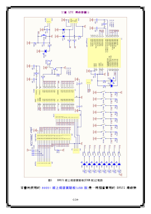
圖189S51線上燒錄實驗板(USB版)之電路本書所使用的89S51線上燒錄實驗板(USB版)是一塊相當實用的89S51燒錄裝當我們的電腦第一次使用89S51線上燒錄實驗板的驅動程式,而驅動程式放置在光碟中之下:1.電腦完成開機後,將89S51線上燒錄實驗板圖所示之對話盒:是,現在以及每次我連接了一個裝置時(E)」選項,再按下圖所示之對話盒:從清單或特定位置安裝(進階)(S)」選項,再按鈕,對話盒改變如下圖所不要搜尋,我將選擇要安裝的驅動程式(D)」選項,再按Windows CE USB Devices」選項,再按鈕,對話盒改變如下圖所示:鈕,螢幕出現如下圖所示之對話盒:將本產品所附之光碟片放入光碟機,再按鈕,對話盒改變如下圖所示:LTC_USBDRV」資料夾選取「ltc.inf」選項,再按鈕,即可返回前一個對話盒,如下圖所示:鈕,螢幕出現如下圖所示之對話盒:鈕,即開始安裝(複製檔案),如下圖所示:安裝完成後,螢幕出現如下圖所示之對話盒,再按鈕關閉此對話盒即可。
除了安裝USB驅動程式外,也要將光碟裡的錄程式),例如放在桌面上。
若要進行燒錄,則直接指向這個程式,快按滑鼠左鍵兩下,即可執行之,螢幕出現如下圖所示之視窗:圖2s51_pgm視窗在此視窗之各項目如下說明:如同一般視窗,在視窗上方為功能表列,包括檔案、測試、讀取、能表,如下說明:圖3版本說明對話盒時,非常管用。
的功能。
晶片內容被讀取。
,相當於能。
雖然程式提供很多功能,實際上的操作卻很簡單!首先將USB埠(固定使用同一個USB埠,以避免麻煩此將介紹幾個實務應用範例:89S51線上燒錄實驗板之聲音與首先啟動 s51_pgm 程式,開啟如圖望春風程式,將89S51線上燒錄實驗板裡的首先啟動 s51_pgm 程式,開啟如圖45所示之程式視窗。
啟動ÎLCD示範命令,即可載入LCD與LED示範程式,將SW1指撥開關全部撥到OFF;若使用英文LCM(16×2),則中間接腳、若使用中文LCM(144×32),則JP4上的跳線連接組(4×4 KeyPad)插入4x4KP埠(Port 2)。
【精品文档】视频会议MCU操作手册

MCS4200 操作手册简介 (1)DST H.323 MCS 4200 (1)设备描述 (1)功能指标 (1)技术规范 (6)MCS 4200 Manager (8)登录设备 (8)登录会议 (8)安装DST H.323 MCS 4200 (9)产品组件 (9)安装条件 (10)设备安装 (10)设备接线 (10)存放 (11)安装MCS 4200 Manager (12)卸载MCS 4200 Manager (20)使用MCS 4200 Manager (21)登录设备 (21)设备管理 (23)参数配置 (23)设备信息: (23)时间管理: (25)网闸管理: (25)网络配置: (25)设置锁定与重启: (26)用户列表 (26)添加设备用户 (28)删除设备用户 (30)修改用户信息 (32)查看用户信息 (36)修改密码 (39)踢掉设备用户 (41)终端列表 (42)刷新 (43)添加终端 (44)删除终端 (45)修改终端信息 (46)清空 (47)保存 (49)导入设备终端列表 (50)导出设备终端列表 (52)分组列表 (54)添加分组 (54)修改分组 (56)删除分组 (58)修改组成员 (59)会议模板 (64)刷新 (65)添加会议模板 (66)注册模板 (81)导入模板 (81)导出模板 (83)查看模板信息 (83)锁定模板 (84)修改模板参数 (87)删除会议模板 (88)调度新会议 (89)会议列表 (90)刷新 (91)查看会议参数 (92)修改会议参数 (93)修改会议邀请列表 (95)删除会议 (97)锁定会议 (98)登录会议 (101)会议调度 (102)基本信息 (102)安全 (104)调度信息 (105)音频/视频 (109)数据服务 (113)实况直播 (115)终端邀请 (116)电视墙 (121)高级 (122)会议控制 (126)登录会议 (126)获得控制权 (127)详细信息和概要信息切换 (131)快捷菜单 (131)邀请终端 (131)全体与会 (133)加密设置 (134)全体退场 (135)双流格式 (136)锁定控制台 (137)退出制界面 (138)指定发言者 (139)指定主席 (140)音频合成 (141)主席轮询 (144)指定与会者的观看目标 (146)请求发言 (146)断开某个与会者 (147)删除终端 (147)取消主席 (148)会议锁定 (149)自动断线重邀 (149)自动授权发言 (149)自动授权混音 (149)带宽优化 (149)如何实现预约会议 (151)如何召开多分屏会议 (152)如何在多分屏会议中加载字幕 (156)如何实现会议直播 (157)如何召开双流会议 (158)如何召开非对称四画面会议 (160)如何召开混速会议 (165)如何召开SIP会议 (167)如何召开AES加密会议 (168)DST Console Utility (169)软件描述 (169)功能介绍 (169)使用DST Console Utility (170)连接电缆 (170)启动终端仿真软件 (170)端口配置参数 (170)软件使用 (172)登录 (172)注销 (173)设置安全超时时间 (174)检查网络连通状态 (174)修改登录口令 (175)口令恢复 (175)显示系统信息 (175)设置IP地址 (176)电视墙相关设置 (178)多网段功能实现 (179)显示路由表 (180)增加路由表 (180)删除路由表 (180)模块管理 (181)系统重置 (181)设置NMC (182)telnet管理 (182)QOS设置 (182)附录A 设备连线 (182)网络连接线 (182)同主机连接 (183)同网络设备连接 (183)附录B 疑难解析 (184)管理软件无法找到MCU (184)控制界面显示当前MCU,但无法进行连接 (184)在会议模板中调度新会议时调度会议的对话框为灰色,无法正常调度会议 (184)调度会议时提示会议资源不足 (184)终端发起会议时不成功 (185)MCU无法呼叫跨路由的终端 (185)无法召开多会议 (185)单画面和四画面有时不能够进行动态切换 (185)召开四分屏会议时画面不清晰或出现马赛克 (185)终端无法呼入会议 (185)会议级联不成功 (185)无法进行语音激励 (186)终端无法申请发言 (186)如何进行远程摄像头控制 (186)会议控制界面的发言栏中总有RS显示 (186)在召开普通模式会议时无法实现轮询 (186)会议进行中进行多画面到单画面转换,观看组播的客户机只能看到多画面 (186)使用Quicktime接收组播时,无法进行正常的观看和收听 (187)会议中画面出现抖动和马赛克现象 (187)通信状态良好,但有噪音 (187)无法登录会议 (187)POLYCOM幻灯片传输注意事项 (188)带宽问题 (188)路由器和防火墙 (188)远端摄像头控制 (188)遥控器无法申请发言 (188)1 简介本文档主要用于向DST H.323 MCS 4200系统的用户或系统管理员提供操作帮助信息,以指导用户正确、快捷地使用DST H.323 MCS4200系统。
激活黑莓自带U盘模式的插件教程

把BB插上USB连接电脑后,解压附件,运行解压出来的批处理文件即可恢复BB的U盘功能,使BB插上USB连接电脑后即能打开自带的U盘功能。
点击mass storage activator插件:
出现一个MS-DOS的窗口,出现以下文字:
RIM Wireless Device command-Line Programmer Version 3.9.0.49
Copyright 2008 Research In Motion Limited
[ Uploading RAM Image 0×1801E6F8 ] [*********100*********]
USBMS: is Enabled1e4h7.
Done.
按任意键继续。
注意:这个批处理文件是循环模式的,如果按照窗口的提示,按任意键继续就会不停的运
行批处理里面的那个命令。
等USBMS: is Enabled1e4h7的文字出来后可以拔下USB连线,关了那个窗口就行了,等待BB重启,重启后再插上USB连接电脑,点击我的
电脑,就会发现多出了“可移动磁盘”点击打开,BB的U盘功能也就恢复了!
用此绝对可以激活BB自带的U盘功能,除非BB给硬解时损坏了部件。
黑莓U盘插件MS-DOS窗口截图.jpg (58.11 KB)。
chipKIT PGM程序员调试器参考手册说明书

1300 Henley CourtPullman, WA 99163509.334.6306 chipKIT™ PGM Programmer/Debugger Reference ManualRevised March 3, 2015This manual applies to the chipKIT PGM rev. AOverviewThe chipKIT PGM is a simple, low cost, module that supports in-system programming and debugging of applications written for Microchip® PIC-based microcontroller boards such as the chipKIT and Cerebot™ boards. The chipKIT PGM is designed to work with the MPLAB® and MPLAB X development environments available from Microchip. This allows the chipKIT boards, for example, to be used as a more traditional microcontroller development platform using the professional tools available from Microchip.The chipKIT PGM can also be used from within the MPLAB or MPLAB-X development environments to enable in-system debugging of sketches developed using the Arduino® compatible MPIDE development environment.chipKIT PGM Hardware OverviewThe chipKIT PGM has the following features:B ConnectorThis is a standard mini USB connector. Use the provided cable to connect the chipKIT PGM to an available USB port on the PC workstation.2.Programming ConnectorConnect the chipKIT PGM to the target board using this connector. The white triangle marker indicatesthe Pin 1 end of the connector.3.Status LEDThis LED indicates that the chipKIT PGM has connected to the target device and is ready for use.4.Activity LEDThis LED is an activity indicator. It blinks when the programmer/debugger software is communicating with the target device.5.Power LEDThis LED illuminates when the chipKIT PGM is receiving power via the USB port from the host PC.Using the chipKIT PGMThe chipKIT PGM uses a programmer/debugger circuit licensed from Microchip. Use of the chipKIT PGM requires a supported version of either the MPLAB IDE or the MPLAB X IDE from Microchip. The licensed debugger is supported in version 8.63 or later of the MPLAB IDE and all versions of the MPLAB X IDE.The MPLAB or MPLAB X IDE can be downloaded from the Microchip web site at: /mplab. These software suites include a free evaluation copy of the Microchip C32 compiler for use with the PIC32 microcontroller family.The appropriate version of the IDE should be downloaded from the Microchip website and installed. This will install the necessary software and drivers to enable use of the chipKIT PGM.Once the desired version of MPLAB has been installed, connect the supplied USB cable to the mini-USB connector on the chipKIT PGM and to an available USB port on the PC.Connect the chipKIT PGM to the ICSP port on the target board and start the MPLAB IDE.The chipKIT PGM behaves similarly to the Microchip PICkit™ 3 Programmer/Debugger and can be used in a similar way.In the MPLAB IDE, select Licensed Debugger from either the Programmer.Select Programmer menu or the Debugger.Select Tool menu. The IDE will connect to the device and identify that it is a 'chipKIT Programmer by Digilent'. When the licensed debugger is selected, the MPLAB IDE will check the version number of the firmware running on the debugger and offer to update it if is out of date with the version of MPLAB being used.At this point, the chipKIT PGM is ready for use.Debugging MPIDE Sketches Using the chipKIT PGMFor detailed information on how to use the chipKIT PGM and the MPLAB IDE to debug MPIDE sketches, please refer to the document “Debugging chipKIT with MPLAB IDE” available on the chipKIT wiki: /wiki. This document is in the Application Notes section at the bottom of the Documenation page on the wiki.CHIPKIT and the CHIPKIT Logo are trademarks or registered trademarks of Microchip Technology Incorporated in the U.S. and other countries, and are used under license.Manufactured by Digilent under license from MICROCHIP.PICkit™ On-Board Programmer/Debugger, © 2011 Microchip Technology Inc. All rights reserved. MICROCHIP SOFTWARE OR FIRMWARE IS PROVIDED “AS IS,” WITHOUT WARRANTY OF ANY KIND, EXPRESS OR IMPLIED, INCLUDING BUT NOT LIMITED TO THE WARRANTIES OF MERCHANTABILITY, FITNESS FOR ANY PARTICULAR PURPOSE AND NONINFRINGEMENT. IN NO EVENT SHALL MICROCHIP BE LIABLE FOR ANY CLAIN, DAMAGES OR OTHER LIABILITY ARISING OUT OF OR IN CONNECTION WITH THE SOFTWARE OR FIRMWARE OR THE USE OF OTHER DEALINGS IN THE SOFTWARE OR FIRMWARE. THIS PRODUCT IS DISTRIBUTED UNDER LICENSE FROM MICROCHIP TECHNOLOGY INC.Declaration of Conformity In accordance with EN ISO/IEC 17050-1:2010Manufacturers Name: Digilent, Inc. Manufacturers Address: 1300 NE Henley Court Pullman, WA 99163 U.S.A.Application of Council Directives: EMC 2004/108/EC Standards: EMC EN55022:2010 EN55024:2010 Product Name: chipKIT PGM Product Model Number: Digilent P/N 210-242 Digilent Product Category: Programming SolutionsWe, the undersigned, hereby declare that the equipment specified above conforms to the above Directives and Standards.Location:_Pullman, WA______ Signature: Clint Cole Date: ___________ August 23, 2012 ___ Full Name (print): Clint Cole Title: _________President___________。
嵌入式Linux下指纹采集模块USB接口驱动程序的设计实现
嵌入式Linux下指纹采集模块USB接口驱动程序的设计实现陈智慧;郭雷;赵天云
【期刊名称】《西安工业大学学报》
【年(卷),期】2012(032)007
【摘要】介绍了嵌入式Linux系统下CMOS光电式指纹采集模块的USB接口驱动程序的设计和实现.概括了Linux系统下USB设备客户端驱动程序开发的一般过程,结合本指纹采集模块USB接口的硬件特点,详细讨论了指纹采集模块的USB接口驱动程序的设计过程.通过该指纹采集模块的USB接口读取指纹信息,实现了指纹采集模块与嵌入式Linux系统的信息传输.结果显示该模块可以采集高质量的指纹图像,实现Linux操作系统和指纹采集模块之间有效可靠的数据通信.该模块尺寸小,可靠性强,可在处于恶劣的工业环境中的嵌入式Linux系统下应用.
【总页数】5页(P545-549)
【作者】陈智慧;郭雷;赵天云
【作者单位】西北工业大学自动化学院,西安 710129;西北工业大学自动化学院,西安 710129;西北工业大学自动化学院,西安 710129
【正文语种】中文
【中图分类】TP302.1
【相关文献】
1.嵌入式Linux下PC/104数据采集模块驱动实现 [J], 吴志勇;鞠传香;郑雯玉
2.基于ARM+Linux平台的USB指纹采集模块设计实现 [J], 施卫明;南余荣
3.基于ARM7和嵌入式Linux系统下USB接口的设计 [J], 李光明;姚斌
4.基于USB接口的指纹检测模块设计实现 [J], 赵应丁;刘金刚
5.基于USB接口的光学指纹采集模块设计 [J], 朱继华;毛幼菊
因版权原因,仅展示原文概要,查看原文内容请购买。
迈普3000_端口操作命令
1.1 以太网端口配置命令........................................................................... 1
第 2 章 端口隔离功能配置命令 .......................................11
2.1 isolate-port group ............................................................................11 2.2 isolate-port group switchport interface .........................................11 2.3 show isolate-port group ................................................................. 12
第 5 章 LLDP 功能命令 ................................................. 21
5.1 lldp enable ....................................................................................... 21 5.2 lldp enable(端口) ......................................................................... 21 5.3 lldp mode ......................................................................................... 21 5.4 lldp tx-interval.................................................................................. 22 5.5 lldp msgTxHold ............................................................................... 22 5.6 lldp transmit delay .......................................................................... 23 5.7 lldp notification interval.................................................................. 23 5.8 lldp trap............................................................................................ 23 5.9 lldp transmit optional tlv................................................................. 24 5.10 lldp neighbors max-num............................................................... 24 5.11 lldp tooManyNeighbors................................................................. 24 5.12 show lldp........................................................................................ 25 2
Maxtor OneTouch USB驱动程序手动安装说明说明书
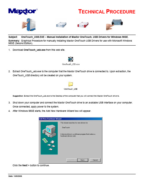
Subject: OneTouch_USB.EXE – Manual Installation of Maxtor OneTouch, USB Drivers for Windows 98SE. Summary: Graphical Procedure for manually installing Maxtor OneTouch USB Drivers for use with Microsoft Windows 98SE (Second Edition).1. Download OneTouch_usb.exe from this web site.2. Extract OneTouch_usb.exe to the computer that the Maxtor OneTouch drive is connected to. Upon extraction, theOneTouch_USB directory will be created on your system.Suggestion: Extract the OneTouch_usb.exe to the Desktop of the computer that you will connect the Maxtor OneTouch drive to.3. Shut down your computer and connect the Maxtor OneTouch drive to an available USB interface on your computer.Once connected, apply power to the system.4. After Windows 98SE starts, the Add New Hardware Wizard box will appear.Click the Next > button to continue.5. On the next page, select "Search for the best driver for your device..." and click the Next > button to continue.6. On the next page, check the "Specify a location:" checkbox and click on the Browse... button.7. In the Browse for Folder Window, locate the OneTouch_USB directory and click the OK button.8. Click on the Next > button to accept the selection of the driver.NOTE: The path identified in the image will vary depending on the location of the file. At this point the Maxtor OneTouch software driver will load on your Windows 98SE computer.9. Click Next > again…10. To complete the installation, click on the Finish button and restart your Windows 98SE computer.11. At this point the Safely Remove Devices Icon will appear in the TaskBar.12. When finished, the Add New Hardware Wizard will appear for a second time. Repeat Steps 1-9 to install theStorage Adapter Bridge Module.。
PXG-E USB Configuration Driver安装指南说明书

PXG-E USB Configuration Driver Installation InstructionsInstall the USB Driver Software (Windows XP)(Also in appendix B of the PXG-E user manual)Once the powerxpert.inf file is downloaded to your PC use the following steps to activate the USB driver this only needs to be done one time for each PC.To install the USB driver software on a computer running Windows XP:1. Select No, not this time and click Next. The Found New Hardware Wizard –Install Software window opens (see Figure 1).Figure 1 - Found New Hardware Wizard – Install Software Window2. Select Install from a list or specific location (Advanced) and click Next. The Found New Hardware Wizard – Installation Options window opens (see Figure 2).Figure 2 - Found New Hardware Wizard – Installation Options Window3. Select Don’t search. I will choose the driver to install. and click Next. The Found New Hardware Wizard – Hardware Type window opens(see Figure 3).Figure 3 - Found New Hardware Wizard – Hardware Type Window4. Select Network adapters and click Next. The Found New Hardware Wizard – Select Network Adapter window opens (see Figure 4).Figure 4 - Found New Hardware Wizard – Select Network Adapter Window5. Select Have Disk. The Install From Disk window opens (see Figure 10). Note: Disregard the instruction to insert the manufacturer’s installation disk in the window. The driver is installed from the powerxpert.inf filedownloaded from the PXG-E web page or mini CD.Figure 5 - Install From Disk Window6. Click Browse. The Locate File window opensLocate and select the folder containing the powerxpert.inf file that you downloaded from the PXG-E web page or mini CD.8. Select powerxpert.inf and click Open. The folder containing the powerxpert.inf file displays in the Copy manufacturer’s file from box (see Figure 6).Figure 6 - Install From Disk Window9. Click OK. The Network Adapter displays in The Found New Hardware Wizard – Select Network Adapter window (see Figure 7).Figure 7 - Found New Hardware Wizard – Select Network Adapter Window10. Select Linux USB Ethernet/RNDIS Gadget and click Next.11. If the caution message shown in Figure 8 displays, click Continue Anyway.Figure 8 - Caution Message12. The wizard installs the software for the USB driver. The Found NewHardware Wizard – Finished Installing the Software window opens(see Figure 9).Figure 9 - Found New Hardware Wizard – Finished Installing the Software Window 13. Click Finish to close the wizard.14. Open the Network Connections window to verify that the installation wassuccessful (see Figure 10). If “Linux USB Ethernet/RNDIS Gadget” is listedin the Device Name column, the USB driver has been successfully installedFigure 10 - Network Connections WindowOnce installation is complete please refer to the PXG-E User Guide, section on Accessing the PXG-E for the model you are going to configure for step by step instructions on accessing using the USB connection. Open a browser and enter the following address http://192.168.200.101.。
- 1、下载文档前请自行甄别文档内容的完整性,平台不提供额外的编辑、内容补充、找答案等附加服务。
- 2、"仅部分预览"的文档,不可在线预览部分如存在完整性等问题,可反馈申请退款(可完整预览的文档不适用该条件!)。
- 3、如文档侵犯您的权益,请联系客服反馈,我们会尽快为您处理(人工客服工作时间:9:00-18:30)。
1. Power off and disconnect the USB cable. 2. Run the USB_driver_install.exe 3. When the left picture is appeared, the install is done. 4. Power on and connect the USB cable. 5. Driver is installed automatically. 6. Open the “Device Manager” to check.
D:\release\driver_install> D:\release\driver_install>wdreg -inf sapgm.inf preinstall WDREG utility v10.10. Build Sep 2 2009 12:19:52 Processing HWID USB\VID_1A29&PID_B0FF Installing a non-signed driver package for USB\VID_1A29&PID_B0FF LOG ok: 1, ENTER: DriverPackagePreinstallA LOG ok: 1, ENTER: DriverPackagePreinstallW LOG ok: 0, D:\release\driver_install\sapgm.inf is preinstalled. LOG ok: 1, RETURN: DriverPackagePreinstallW (0x0) LOG ok: 1, RETURN: DriverPackagePreinstallA (0x0) difx_install_preinstall_inf: err 0, last event 0, last error 0. SUCCESS preinstall: completed successfully
D:\release\driver_install>wdreg -inf windrvr6.inf install WDREG utility v10.10. Build Sep 2 2009 12:19:52 Processing HWID *WINDRVR6 Installing a signed driver package for *WINDRVR6 LOG ok: 1, ENTER: DriverPackageInstallA LOG ok: 1, ENTER: DriverPackageInstallW LOG ok: 1, Looking for Model Section [DeviceList]... LOG ok: 1, Installing INF file 'D:\release\driver_install\windrvr6.inf' (P lug and Play). LOG ok: 1, Looking for Model Section [DeviceList]... LOG ok: 1, Installing devices with Id "*WINDRVR6" using INF "C:\Windows\system32 \DriverStore\FileRepository\windrvr6.inf_0e983cb3\windrvr6.inf". LOG ok: 1, ENTER UpdateDriverForPlugAndPlayDevices... LOG ok: 0, RETURN UpdateDriverForPlugAndPlayDevices. LOG ok: 1, Installation was successful. LOG ok: 0, Install completed LOG ok: 1, RETURN: DriverPackageInstallW (0x0) LOG ok: 1, RETURN: DriverPackageInstallA (0x0) difx_install_preinstall_inf: err 0, last event 0, last error 0. SUCCESS install: completed successfully
Above Log is displayed in the DOS Command window during stalling the driver.