A QKD Protocol Extendable to Support Entanglement and Reduce Unauthorized Information Gain
USB3 Type-C Specification State Machine

The USB Type-C Cable and Connector Specification defines a standardized mechanism that supports Alternate Modes, such as repurposing the connector for docking-specific applications. 1.2 Scope This specification is intended as a supplement to the existing USB 2.0 , USB 3.1 and USB Power Delivery specifications. It addresses only the elements required to implement and support the USB Type-C receptacles, plugs and cables. Normative information is provided to allow interoperability of components designed to this specification. Informative information, when provided, may illustrate possible design implementations.
The USB Type-C Cable and Connector Specification defines a new receptacle, plug, cable and detection mechanisms that are compatible with existing USB interface electrical and functional specifications. This specification covers the following aspects that are needed to produce and use this new USB cable/connector solution in newer platforms and devices, and that interoperate with existing platforms and devices: USB Type-C receptacles, including electro-mechanical definition and performance requirements USB Type-C plugs and cable assemblies, including electro-mechanical definition and performance requirements USB Type-C to legacy cable assemblies and adapters USB Type-C-based device detection and interface configuration, including support for legacy connections USB Power Delivery optimized for the USB Type-C connector
EqualLogic 阵列软件说明书

The tools you need to virtualize, optimize and protect your dataWith EqualLogic Array Software, you don’t need tochoose between data protection and performance. EqualLogic Array Software automatically virtualizes and optimizes resources within the SAN to deliver consistent application performance and features all the tools required for developing a sound data protection strategy. The EqualLogic Array Software family includes EqualLogic Firmware, EqualLogic Group Manager and EqualLogic Manual Transfer Utility.Delivering consistent performance with EqualLogic FirmwareEqualLogic Firmware is a SAN operating system integrated across the entire family of EqualLogic storage arrays; which virtualizes SAN resources and provides intelligent data management functionality. An essential component of the software is the capability to automatically adjust system resources, optimizing performance and capacity, and reducing human intervention.EqualLogic Firmware is a full-function SAN operating system providing features natively that are often expensive add-ons with other SAN vendors. Features like automatic load-balancing, thin provisioning, snapshots, replication and multi-path I/O are just a few of the features integrated in EqualLogic Firmware.You control the infrastructure and we make it workEqualLogic Group Manager is a SAN managementtool integrated with the EqualLogic Firmware that provides detailed information on SAN configuration, and provides storage managers with an easy-to-use tool for storage provisioning, replication scheduling and array management. The EqualLogic Group Manager is available as a command line interface (CLI) or java based graphical user interface (GUI) that can be accessed from Microsoft®Internet Explorer® or Mozilla® Firefox® web browsers with a connection to the EqualLogic SAN.EqualLogic Manual Transfer Utility is a host based tool that enables the secure transfer of large amounts of data using removable media. Integrated with the native replication function of the EqualLogic Firmware, EqualLogic Manual Transfer Utility is beneficial in environments where data protection is critical but bandwidth is limited. Investment protection with all-inclusive SAN solutionsWith the EqualLogic family of storage arrays, Dell provides comprehensive SAN solutions designed to meet a wide range of business needs. For one price, customers receive a fault-tolerant, fully-redundant array, as well as all the software features required to virtualize, optimize and protect their data; all this without the management hassles that come with multiple software licenses or support contracts. Additionally, customers who commit to a yearly Dell ProSupport* contract can implement new software features and enhancements as they become available, extending the value of their investment in EqualLogic products.Dell EqualLogic Array SoftwareDell™ delivers three categories of software for the EqualLogic™ family of storage arrays. EqualLogic Array Software provides advanced SAN functions that enable virtualized storage and best-practice data protection. EqualLogic Host Software extends the functionality of the array software enabling cooperation with the host. EqualLogic SAN Headquarters is a feature-rich monitoring and analysis tool that provides in-depth information on SAN functions providing storage managers with the toolsneeded to tune and optimize their storage infrastructure.†GB means 1 billion bytes, TB equals 1 trillion bytes and PB equals 1 quadrillion bytes; actual capacity varies with preloaded material and operating environment and will be less.. *Availability and terms of Dell Services vary by region. For more information, visit /servicedescriptions© 2010 Dell Inc. All rights reserved. Microsoft, Windows and Windows Vista are registered trademarks of Microsoft Corporation in the United States and/or other countries.Simplify your storage at /PSseriesSS654_EqualLogic_Array_Software_Spec_Sheet_113009_051910。
3GPP移动通信标准TS4.08v800

word完美格式GSM 04.08 8.0.0 (1999-07)European Standard (Telecommunications series)Digital cellular telecommunications system (Phase 2+);Mobile radio interface layer 3 specification(GSM 04.08 version 8.0.0 Release 1999)Available SMG onlyRGLOBAL SYSTEM FORMOBILE COMMUNICATIONSReferenceREN/SMG-030408Q8 (8pc030o0.PDF)KeywordsDigital cellular telecommunications system,Global System for Mobile communications(GSM)ETSIPostal addressF-06921 Sophia Antipolis Cedex - FRANCEOffice address650 Route des Lucioles - Sophia AntipolisValbonne - FRANCETel.: +33 4 92 94 42 00 Fax: +33 4 93 6547 16Siret N° 348 623 562 00017 - NAF 742 CAssociation à but non lucratif enregistrée à laSous-Préfecture de Grasse (06) N° 7803/88Internetsecretariat@etsi.frIndividual copies of this ETSI deliverablecan be downloaded fromCopyright NotificationNo part may be reproduced except as authorized by written permission.The copyright and the foregoing restriction extend to reproduction in all media.© European Telecommunications Standards Institute 1999.All rights reserved.ContentsIntellectual Property Rights (5)Foreword (5)Introduction (5)1 Scope (6)2 Normative references (6)2.1 Definitions and abbreviations (10)2.2 Random values (11)2.3 Vocabulary (11)3 Radio Resource management procedures (11)4 Elementary procedures for Mobility Management (11)5 Elementary procedures for circuit-switched Call Control (11)6 Support for packet services (11)7 Examples of structured procedures (11)8 Handling of unknown, unforeseen, and erroneous protocol data (11)9 Message functional definitions and contents (11)9.1 Messages for Radio Resources management (11)9.2 Messages for mobility management (12)9.3 Messages for circuit-switched call control (12)9.4 GPRS Mobility Management Messages (12)9.5 GPRS Session Management Messages (12)10 General message format and information elements coding (12)10.1 Overview (12)10.2 Protocol Discriminator (12)10.3 Skip indicator and transaction identifier (12)10.4 Message Type (12)10.5 Other information elements (12)10.5.1 Common information elements. (12)10.5.2 Radio Resource management information elements. (13)10.5.3 Mobility management information elements. (14)10.5.4 Call control information elements. (14)10.5.5 GPRS mobility management information elements (14)10.5.6 Session management information elements (14)11 List of system parameters (14)Annex A (informative): Example of subaddress information element coding (15)Annex B (normative): Compatibility checking (15)Annex C (normative): Low layer information coding principles (15)Annex D (informative): Examples of bearer capability information element coding (15)Annex E (informative): Comparison between call control procedures specified inGSM 04.08 and CCITT Recommendation Q.931 (15)Annex F (informative): GSM specific cause values for radio resource management (15)Annex G (informative): GSM specific cause values for mobility management (15)Annex H (informative): GSM specific cause values for call control (16)Annex I (informative): GSM specific cause values for session management (16)Annex J (informative): Algorithm to encode frequency list information elements (16)Annex K (informative): Default Codings of Information Elements (16)Annex L: Additional Requirements for backward compatibility withPCS 1900 for NA revision 0 ME. (16)Annex M (informative): Change Record (17)History (18)Intellectual Property RightsIPRs essential or potentially essential to the present document may have been declared to ETSI. The information pertaining to these essential IPRs, if any, is publicly available for ETSI members and non-members, and can be found in SR 000 314: "Intellectual Property Rights (IPRs); Essential, or potentially Essential, IPRs notified to ETSI in respect of ETSI standards", which is available free of charge from the ETSI Secretariat. Latest updates are available on the ETSI Web server (/ipr).Pursuant to the ETSI IPR Policy, no investigation, including IPR searches, has been carried out by ETSI. No guarantee can be given as to the existence of other IPRs not referenced inSR 000 314 (or the updates on the ETSI Web server) which are, or may be, or may become, essential to the present document.ForewordThis European Standard (Telecommunications series) has been produced by ETSI Special Mobile Group (SMG).This EN specifies the procedures used at the radio interface (Reference Point Um, seeGSM 04.02) for Call Control (CC), Mobility Management (MM) and Radio Resource (RR) management within the digital cellular telecommunications system.The contents of this EN are subject to continuing work within SMG and may change followingformal SMG approval. Should SMG modify the contents of this EN it will then be re-submitted for OAP with an identifying change of release date and an increase in version number as follows:Version 8.x.ywhere:8 indicates GSM Release 1999 of Phase 2+x the second digit is incremented for all changes of substance, i.e. technical enhancements, corrections, updates, etc.y the third digit is incremented when editorial only changes have been incorporated in the specification.IntroductionThe present document includes references to features which are not part of the Phase 2+Release 96 of the GSM Technical specifications. All subclauses which were changed as a resultof these features contain a marker (see table below) relevant to the particular feature.The following table lists all features that were introduced after Release 96.1 ScopeThis EN specifies the procedures used at the radio interface (Reference Point Um, seeGSM 04.02) for Call Control (CC), Mobility Management (MM), Radio Resource (RR) management and Session Management (SM). The detailed descriptions of the protocols and the related procedures are described in GSM 04.18, TS 23.108 and TS 24.008.When the notations for "further study" or "FS" or "FFS" are present in this ETS they mean that the indicated text is not a normative portion of this standard.These procedures are defined in terms of messages exchanged over the control channels of the radio interface. The control channels are described in GSM 04.03.The structured functions and procedures of this protocol and the relationship with other layers and entities are described in general terms in GSM 04.07.2 Normative referencesThe following documents contain provisions which, through reference in this text, constitute provisions of the present document.- References are either specific (identified by date of publication, edition number, version number, etc.) or non-specific.- For a specific reference, subsequent revisions do not apply.- For a non-specific reference, the latest version applies.- A non-specific reference to an ETS shall also be taken to refer to later versions published as an EN with the same number.- For this Release 1999 document, references to GSM documents are for Release 1999 versions (version 8.x.y).[1] GSM 01.02: "Digital cellular telecommunications system (Phase 2+); Generaldescription of a GSM Public Land Mobile Network (PLMN)".[2] GSM 01.04: "Digital cellular telecommunications system (Phase 2+);Abbreviations and acronyms".[3] TS 22.002: "Digital cellular telecommunications system (Phase 2+); BearerServices (BS) supported by a GSM Public Land Mobile Network (PLMN)".[4] GSM 02.03: "Digital cellular telecommunications system (Phase 2+);Teleservices supported by a GSM Public Land Mobile Network (PLMN)".[5] GSM 02.09: "Digital cellular telecommunications system (Phase 2+); Securityaspects".[6] TS 22.011: "Digital cellular telecommunications system (Phase 2+); Serviceaccessibility".[7] GSM 02.17: "Digital cellular telecommunications system (Phase 2+); Subscriberidentity modules Functional characteristics".[8] GSM 02.40: "Digital cellular telecommunications system (Phase 2+); Proceduresfor call progress indications".[9] GSM 03.01: "Digital cellular telecommunications system (Phase 2+); Networkfunctions".[10] TS 23.003: "Digital cellular telecommunications system (Phase 2+);Numbering, addressing and identification".[11] GSM 03.13: "Digital cellular telecommunications system (Phase 2+);Discontinuous Reception (DRX) in the GSM system".[12] TS 23.014: "Digital cellular telecommunications system (Phase 2+); Support ofDual Tone Multi-Frequency signalling (DTMF) via the GSM system".[12a] TS 23.071: “Digital cellular telecommunications system (Phase2+); Location Services; Functional description –Stage 2”.[13] GSM 03.20: "Digital cellular telecommunications system (Phase 2+); Securityrelated network functions".[14] TS 23.022: "Digital cellular telecommunications system (Phase 2+); Functionsrelated to Mobile Station (MS) in idle mode".[15] GSM 04.02: "Digital cellular telecommunications system (Phase 2+);GSM Public Land Mobile Network (PLMN) access reference configuration".[16] GSM 04.03: "Digital cellular telecommunications system (Phase 2+); MobileStation - Base Station System (MS - BSS) interface Channel structures andaccess capabilities".[17] GSM 04.04: "Digital cellular telecommunications system (Phase 2+); layer 1General requirements".[18] GSM 04.05: "Digital cellular telecommunications system (Phase 2+); Data Link(DL) layer General aspects".[19] GSM 04.06: "Digital cellular telecommunications system (Phase 2+); MobileStation - Base Station System (MS - BSS) interface Data Link (DL) layerspecification".[20] TS 24.007: "Digital cellular telecommunications system (Phase 2+); Mobileradio interface signalling layer 3; General aspects".[21] TS 24.010: "Digital cellular telecommunications system ; Mobile radiointerface layer 3 Supplementary services specification; General aspects".[22] GSM 04.11: "Digital cellular telecommunications system (Phase 2); Point-to-Point (PP) Short Message Service (SMS) support on mobile radio interface".[23] GSM 04.12: "Digital cellular telecommunications system (Phase 2+); ShortMessage Service Cell Broadcast (SMSCB) support on the mobile radio interface".[23a] TS 24.071: “Digital cellular telecommunications system (Phase2+); Mobile radio interface layer 3 location services specification.[24] TS 24.080: "Digital cellular telecommunications system (Phase 2+); Mobileradio interface layer 3 supplementary services specification Formats andcoding".[25] TS 24.081: "Digital cellular telecommunications system (Phase 2+); Lineidentification supplementary services - Stage 3".[26] TS 24.082: "Digital cellular telecommunications system (Phase 2+); CallForwarding (CF) supplementary services - Stage 3".[27] TS 24.083: "Digital cellular telecommunications system (Phase 2+); CallWaiting (CW) and Call Hold (HOLD) supplementary services - Stage 3".[28] TS 24.084: "Digital cellular telecommunications system (Phase 2+); MultiParty(MPTY) supplementary services - Stage 3".[29] TS 24.085: "Digital cellular telecommunications system (Phase 2+); ClosedUser Group (CUG) supplementary services - Stage 3".[30] TS 24.086: "Digital cellular telecommunications system (Phase 2+); Advice ofCharge (AoC) supplementary services - Stage 3".[31] GSM 04.88: "Digital cellular telecommunications system (Phase 2+); CallBarring (CB) supplementary services - Stage 3".[32] GSM 05.02: "Digital cellular telecommunications system (Phase 2+);Multiplexing and multiple access on the radio path".[33] GSM 05.05: "Digital cellular telecommunications system (Phase 2+); Radiotransmission and reception".[34] GSM 05.08: "Digital cellular telecommunications system (Phase 2+); Radiosubsystem link control".[35] GSM 05.10: "Digital cellular telecommunications system (Phase 2+); Radiosubsystem synchronization".[36] TS 27.001: "Digital cellular telecommunications system (Phase 2+); Generalon Terminal Adaptation Functions (TAF) for Mobile Stations (MS)".[37] TS 29.002: "Digital cellular telecommunications system (Phase 2+); MobileApplication Part (MAP) specification".[38] TS 29.007: "Digital cellular telecommunications system (Phase 2+); Generalrequirements on interworking between the Public Land Mobile Network (PLMN) andthe Integrated Services Digital Network (ISDN) or Public Switched TelephoneNetwork (PSTN)".[39] GSM 11.10: "Digital cellular telecommunications system (Phase 2+); MobileStation (MS) conformity specification".[40] GSM 11.21: "Digital cellular telecommunications system (Phase 2); TheGSM Base Station System (BSS) equipment specification".[41] ISO/IEC 646 (1991): "Information technology - ISO 7-bit coded character setfor information interchange".[42] ISO/IEC 6429: "Information technology - Control functions for coded charactersets".[43] ISO 8348 (1987): "Information processing systems - Data communications -Network service definition".[44] CCITT Recommendation E.163: "Numbering plan for the international telephoneservice".[45] CCITT Recommendation E.164: "Numbering plan for the ISDN era".[46] CCITT Recommendation E.212: "Identification plan for land mobile stations".[47] ITU-T Recommendation F.69 (1993): "Plan for telex destination codes".[48] CCITT Recommendation I.330: "ISDN numbering and addressing principles".[49] CCITT Recommendation I.440 (1989): "ISDN user-network interface data linklayer - General aspects".[50] CCITT Recommendation I.450 (1989): "ISDN user-network interface layer 3General aspects".[51] ITU-T Recommendation I.500 (1993): "General structure of the ISDN interworkingrecommendations".[52] CCITT Recommendation T.50: "International Alphabet No. 5".[53] CCITT Recommendation Q.931: ISDN user-network interface layer 3 specificationfor basic control".[54] CCITT Recommendation V.21: "300 bits per second duplex modem standardized foruse in the general switched telephone network".[55] CCITT Recommendation V.22: "1200 bits per second duplex modem standardized foruse in the general switched telephone network and on point-to-point 2-wireleased telephone-type circuits".[56] CCITT Recommendation V.22bis: "2400 bits per second duplex modem using thefrequency division technique standardized for use on the general switchedtelephone network and on point-to-point 2-wire leased telephone-type circuits".[57] CCITT Recommendation V.23: "600/1200-baud modem standardized for use in thegeneral switched telephone network".[58] CCITT Recommendation V.26ter: "2400 bits per second duplex modem using theecho cancellation technique standardized for use on the general switchedtelephone network and on point-to-point 2-wire leased telephone-type circuits".[59] CCITT Recommendation V.32: "A family of 2-wire, duplex modems operating atdata signalling rates of up to 9600 bit/s for use on the general switchedtelephone network and on leased telephone-type circuits".[60] CCITT Recommendation V.110: "Support of data terminal equipments (DTEs) withV-Series interfaces by an integrated services digital network".[61] CCITT Recommendation V.120: "Support by an ISDN of data terminal equipmentwith V-Series type interfaces with provision for statistical multiplexing".[62] CCITT Recommendation X.21: "Interface between data terminal equipment (DTE)and data circuit-terminating equipment (DCE) for synchronous operation onpublic data networks".[63] CCITT Recommendation X.25: "Interface between data terminal equipment (DTE)and data circuit-terminating equipment (DCE) for terminals operating in thepacket mode and connected to public data networks by dedicated circuit".[64] CCITT Recommendation X.28: "DTE/DCE interface for a start-stop mode dataterminal equipment accessing the packet assembly/disassembly facility (PAD) ina public data network situated in the same country".[65] CCITT Recommendation X.30: "Support of X.21, X.21 bis and X.20 bis based dataterminal equipments (DTEs) by an integrated services digital network (ISDN)".[66] CCITT Recommendation X.31: "Support of packet mode terminal equipment by anISDN".[67] CCITT Recommendation X.32: "Interface between data terminal equipment (DTE)and data circuit-terminating equipment (DCE) for terminals operating in thepacket mode and accessing a packet switched public data network through apublic switched telephone network or an integrated services digital network ora circuit switched public data network".[68] CCITT Recommendation X.75 (1988): "Packet-switched signalling system betweenpublic networks providing data transmission services".[69] CCITT Recommendation X.121: "International numbering plan for public datanetworks".[70] ETS 300 102-1: "Integrated Services Digital Network (ISDN); User-networkinterface layer 3 Specifications for basic call control".[71] ETS 300 102-2: "Integrated Services Digital Network (ISDN); User-networkinterface layer 3 Specifications for basic call control".[72] ISO/IEC10646: “Universal Multiple-Octet Coded Character Set (UCS)”; UCS2, 16bit coding.[73] TS 22.060: "Digital cellular telecommunications system (Phase 2+); GeneralPacket Radio Service (GPRS); Service Description; Stage 1".[74] TS 23.060: "Digital cellular telecommunications system (Phase 2+); GeneralPacket Radio Service (GPRS); Service Description; Stage 2".[75] GSM 03.64: "Digital cellular telecommunications system (Phase 2+); GeneralPacket Radio Service (GPRS); Overall description of the GPRS radio interface;Stage 2".[76] GSM 04.60: "Digital cellular telecommunications system (Phase 2+); GeneralPacket Radio Service (GPRS); Mobile Station - Base Station System (MS-BSS)interface; Radio Link Control and Medium Access Control (RLC/MAC) layerspecification".[77] IETF RFC 1034: "Domain names - Concepts and Facilities " (STD 7).[78] GSM 04.65: "Digital cellular telecommunications system (Phase 2+); GeneralPacket Radio Service (GPRS); Subnetwork Dependent Convergence Protocol(SNDCP)".[79] TS 24.008: "3rd Generation Partnership Project; Technical Specification GroupCore Network; Mobile Radio Interface Layer 3 specification; Core NetworkProtocols - Stage 3".[80] TS 23.108: "3rd Generation Partnership Project; Technical Specification GroupCore Network; Mobile Radio Interface Layer 3 specification; Core NetworkProtocols - Stage 2".[81] GSM 04.18: ""Digital cellular telecommunications system (Phase 2+); MobileRadio Interface Layer 3 specification; Radio Resource Control Protocol".2.1 Definitions and abbreviationsAbbreviations used in this specification are listed in GSM 01.042.2 Random valuesFor RR see 4.18 and for Core Network Protocols see 24.0082.3 VocabularyFor RR see 4.18 and for Core Network Protocols see 24.0083 Radio Resource management proceduresSee 04.184 Elementary procedures for Mobility Management See 24.0085 Elementary procedures for circuit-switched CallControlSee 24.0086 Support for packet servicesSee 24.0087 Examples of structured proceduresSee 23.1088 Handling of unknown, unforeseen, and erroneousprotocol dataFor RR see 04.18 and for Core Network protocols see 24.1089 Message functional definitions and contentsFor RR see 04.18 and for Core Network protocols see 24.1089.1 Messages for Radio Resources managementSee 04.189.2 Messages for mobility managementSee 24.0089.3 Messages for circuit-switched call controlSee 24.0089.4 GPRS Mobility Management MessagesSee 24.0089.5 GPRS Session Management MessagesSee 24.00810 General message format and information elementscodingFor RR see 04.18 and for Core Network protocols see 24.008.10.1 OverviewFor RR see 04.18 and for Core Network protocols see 24.008.10.2 Protocol DiscriminatorFor RR see 04.18 and for Core Network protocols see 24.008.10.3 Skip indicator and transaction identifierFor RR see 04.18 and for Core Network protocols see 24.008.10.4 Message TypeFor RR see 04.18 and for Core Network protocols see 24.008.10.5 Other information elementsFor RR see 04.18 and for Core Network protocols see 24.008.10.5.1 Common information elements.See 24.00810.5.2 Radio Resource management information elements. See 04.1810.5.3 Mobility management information elements.See 24.00810.5.4 Call control information elements.See 24.00810.5.5 GPRS mobility management information elements See 24.00810.5.6 Session management information elementsSee 24.00811 List of system parametersFor RR see 04.18 and for Core Network protocols see 24.008Annex A (informative):Example of subaddress information element codingSee 24.008 Annex A.Annex B (normative):Compatibility checkingSee 24.008 Annex B.Annex C (normative):Low layer information coding principlesSee 24.008 Annex C.Annex D (informative):Examples of bearer capability information element codingSee 24.008 Annex D.Annex E (informative):Comparison between call control procedures specified in GSM 04.08 and CCITT Recommendation Q.931See 24.008 Annex E.Annex F (informative):GSM specific cause values for radio resource managementSee 04.18 Annex F.Annex G (informative):GSM specific cause values for mobility managementSee 24.008 Annex G.Annex H (informative):GSM specific cause values for call controlSee 24.008 Annex H.Annex I (informative):GSM specific cause values for session management See 24.008 Annex I.Annex J (informative):Algorithm to encode frequency list information elementsSee 04.18 Annex J.Annex K (informative):Default Codings of Information ElementsFor RR See 04.18 Annex K and for Core Network protocols see 24.008 annex K.Annex L: Additional Requirements for backward compatibility with PCS 1900 for NA revision 0 ME.See 24.008 Annex LAnnex M (informative):Change RecordSplit to RAN and CN parts based on version 7.1.0 and inclusion of CRsHistory。
blocked mirrors for repositories -回复

blocked mirrors for repositories -回复"Blocked Mirrors for Repositories"In the world of software engineering and development, the use of code repositories has become increasingly vital. These repositories are online platforms that allow developers to store and share their code with peers and the wider community. They ensure collaboration, version control, and transparency. However, there are instances when certain mirrors for these repositories are blocked. In this article, we will explore the reasons behind blocked mirrors and the steps to overcome these challenges.1. Understanding Blocked MirrorsA blocked mirror refers to a code repository or its specific clone that has been rendered inaccessible or restricted in a particular region or network. Various factors contribute to the blocking, such as government regulations, server issues, or intentional filtering by network administrators. While blocked mirrors can cause inconvenience and complexity, it is important to understand the motivations behind the blocking to find appropriate solutions.2. Reasons Behind Blockinga. Government Regulations: Governments may block certain mirrors due to political, security, or legal reasons. In some cases, countries restrict access to code repositories that contain sensitive or controversial content. These restrictions aim to control information flow, prevent software piracy, or enforce intellectual property rights.b. Server Issues: Blocked mirrors can also result from server issues, technical glitches, or network outages. These could be temporary and resolved once the hosting provider rectifies the problem. In such cases, the blockage is unrelated to intentional restrictions.c. Intentional Filtering: Network administrators or organizations may block mirrors to regulate bandwidth usage, improve network performance, or restrict access to non-essential resources. These actions can be a part of network management strategies or security measures.3. Steps to Overcome Blocked Mirrorsa. Utilizing Alternative Mirrors: When a mirror is blocked, developers can turn to alternative mirrors that are accessible in their region. Many code repositories have multiple mirrors spreadacross different servers or CDNs (Content Delivery Networks). Checking repository documentation or reaching out to the repository's support team can help identify alternative mirrors.b. Utilizing Cloaking or VPN Services: Cloaking or VPN (Virtual Private Network) services can help bypass blocked mirrors by posing as an intermediary between the user and the blocked content. These services allow users to connect to a server in a different location, thereby circumventing the blocking restrictions. It is crucial to select reputable VPN providers to ensure privacy and security.c. Local Hosting: In some cases, developers may choose to create their local mirror by cloning the repository onto their own servers or infrastructure. This approach ensures complete control over the repository and eliminates dependency on external mirrors. However, it requires continuous synchronization with the original repository to stay up-to-date.d. Initiating Dialogue and Collaboration: If the blocking is due to government regulations, developers can engage in discussions with relevant authorities or agencies to address concerns and seeksolutions. Collaborating with peers, user communities, oropen-source advocacy groups can also raise awareness and contribute to collective efforts in resolving blockage issues.e. Building Redundancy: Developers and organizations can proactively build redundancy and diversify their repository mirror choices. This involves periodically backing up important code repositories on multiple platforms or servers. By doing so, developers can mitigate the impact of a blocked mirror, ensuring continuous access to code.4. ConclusionBlocked mirrors for repositories can pose challenges for developers and impede collaboration and innovation. Understanding the reasons behind blocked mirrors, such as government regulations, server issues, or intentional filtering, helps in finding appropriate solutions. By utilizing alternative mirrors, cloaking or VPN services, local hosting, initiating dialogue, and building redundancy, developers can overcome these challenges and continue to access and contribute to code repositories seamlessly. Open dialogue,collective efforts, and technological solutions enable the software development community to thrive even in the face of blocked mirrors.。
DF1协议常用命令

DF1协议常⽤命令PCCC:Programmable Controller Communication Commands.AB PLC常⽤指令The best commands for SLC5/MicroLogix controllers are:Protected Typed Logical Read with 3-Address Fields (Cmd=0x0F, SubFnc=0xA2)Protected Typed Logical Write with 3-Address Fields (Cmd=0x0F, SubFnc=0xAA)Protected Typed Logical Masked-Write with 3-Address Fields (Cmd=0x0F, SubFnc=0xAB)Protected Typed Logical Read with 2-Address Fields (Cmd=0x0F, SubFnc=0xA1)Protected Typed Logical Write with 2-Address Fields (Cmd=0x0F, SubFnc=0xA9)Only the first two (0xA2/AA) are documented in the official DF1 protocol specification. The third (0xAB) is not documented but is commonly used by OPC servers; In fact a Rockwell engineer formally sent me details of it when I asked; it is not considered "secret".The last two (0xA1/A9) are only of value if you're creating a slave driver since a few of Rockwell's software tools assume these are supported. While they are not documented in the DF1 specification, RSLogix5000 outlines support for them as part of its legacy support for PCCC messages. But there is no reason for an OPC server or master to use 0xA1/A9 since support by slaves is not universal. Using SubFnc 0xA1 instead of 0xA2 just drops one unrequired NULL byte from the command, so is of modest value. For example, to read N7:1 your Read command would include the 6 bytes "A2 02 07 89 01 00" for the 3-Address Fields form and only the 5 bytes "A1 02 07 89 01" for the 2-Address Fields form. Big deal, eh? Well, yes - a big deal if you try to use 0xA1 with a slave that doesn't understand 0xA1.怎样单独写⼀位:How do I write single bits on a SLC5/MicroLogix?use the undocumented (but well supported) Cmd=0x0F SubFnc=0xAB Masked WriteThe command looks much like the documented Protected Typed Logical Write with 3-Address Fields (Cmd=0x0F, SubFnc=0xAA) except you'll find an added 16-bit word of data. So here are examples of each:0xAA 02 03 85 00 00 01 000xAB 02 03 85 00 00 01 00 01 000xAB 04 03 85 00 00 01 00 01 00 00 00The first command (0xAA) in effect clears bits B3:0/1 to B3:0/15 and sets bit B3:0/0. So the entire first word of the B3 table is changed -often not the desired action. In contrast, the second command (0xAB) just sets B3:0/0 to 1 without affecting the other 15 bits of B3:0.Notice that the 16-bit "mask" is not included in the byte count of 2. The third command (0xAB) shows that more than one data word can be sent, but there is always just a single 16-bit mask. The third command would set B3:0/0 to "1" and clear B3:1/0 to "0". If you - for example - desire to set both bits B3:0/0 and B3:1/6 to "1", then you'd need to issue two separate commands since they don't share the same 16-bit mask. AB PLC常⽤指令--具体A2指令--protected typed logical read with three address fieldsReads data from a logical address in a SLC 500 module读取N7:1⼀个字(2bytes)request: 10 02 01 00 0F 00 36 0D A2 02 07 89 01 00 10 03 80 D8reply: 10 06 10 02 00 01 4F 00 36 0D E8 03 10 03 75 65读取N7:0五个字(10bytes)request: 10 02 01 00 0F 00 08 52 A2 0A 07 89 00 00 10 03 8D 4Dreply: 10 06 10 02 00 01 4F 00 08 52 D0 07 E8 03 00 00 00 00 00 00 10 03 5F E2AA指令--protected typed logical write with three address fieldsWrites data to a logical address in a SLC processor写B3:0request: 10 02 01 00 0F 00 08 54 AA 04 03 85 00 00 03 00 01 00 10 03 DB B2 reply: 10 06 10 02 00 01 4F 00 08 54 10 03 AB 1C 10 05 10 05 10 05 10 05⽰例⼀组PLC数据定义:DF1协议DF1协议控制字符DF1协议传输标志DF1协议链路协议帧Half-duplexFull-duplexDF1协议应⽤帧。
K宝K Po使用说明 优质课件

• 2) select Internet Options;
• 3) Select [Content] tab in the [certificate] button;
• 4) you can see just downloaded the certificate is registered to IE;
K-management tools
Click Start - Programs - Agricultural Bank of China online banking certificate tools - Flying - Management Tools, you can open the K-management tools.
• 1) Windows XP system:
• K treasure into the USB port, it will automatically install the disc breaks at the same time will display the Logo of the Agricultural Bank of China, as shown: Click "Close" to complete the installation.
k宝k po使用说明 agriculturalbank pousing instructionmanual (feitian) four essentials treasurefirst downloadk-certificate pomanagement tools commonproblems poused firsttime windows-basedproduct, needmanually install poinserted usbport treasuredefault installation operatingenvironment. computerused firsttime windows2000 lateroperating systems, windows xp windowsvista, example.1.installed default"auto play" state windowsxp system: usbport, automaticallyinstall discbreaks sametime agriculturalbank shown:click "close" windowsvista system xpinstallation somewhatdifferent, usbport, followingscreen appearwhen you tap runabchina.exe], click[continue] installed.finally, followingscreen appears click "close" installation.2.the status "autoplay" yourcomputer openmy computer, right click cddrive letter agriculturalbank china,click "open"; figure: step two: open, double-click feitian.exe installation;k-download loginhome agriculturalbank leftside "certificatewizard, click personalcertificate download "button cer
INTRODUCTIONTOINFORMATIONSYSTEMS信息系统导论

System 1
Program 1
File 1
Program 2
File 1
File 2
File 2
File 3
File 3
System 2
10
What does the Manufacturing ERP component allow?
10
Name some of the activities it handles
Name the three major ERP software vendors
12
What are the success factors of ERP implementation?
7
system
Enterprise Resource Planning Systems
ERP systems automate business processes
8
ERP Components (or Modules)
Two types of components
Core ERP Components Extended ERP Components
the Internet)
10
ERP Components (or Modules)
ERP mainly used by medium and large businesses
Average lifetime cost: $15 Million (2010 surveys) Implementation process: up to 5 years
博科存储网络运维指导手册

博科存储网络运维指导手册V ERSION 1.02016年7月文档修订记录文档编号:标题博科存储网络运维指导手册摘要本文档是为博科存储网络定制的运维指导手册当前版本V1.0创建日期2016-7文档作者舒磊文件名称博科存储网络维指导手册.doc修改记录日期修改人编写者摘要目录文档修订记录.................................................................................................................................... I I 目录.................................................................................................................................................. I II 前言 (1)文档目的 (1)编写环境 (1)适用人员 (1)内容范围 (1)一、网络架构描述 (2)二、主要运维场景 (4)1.端口故障 (4)具体现象 (4)故障信息确认 (4)故障处理 (7)影响范围 (14)预计处理时间 (14)验证方案 (14)2.磁盘访问故障 (15)具体现象 (15)故障信息确认 (15)故障处理 (15)影响范围 (17)预计处理时间 (17)验证方案 (17)3.端口板故障 (18)具体现象 (18)故障信息确认 (18)故障处理 (19)影响范围 (20)预计处理时间 (20)验证方案 (21)4.引擎故障 (21)具体现象 (21)故障信息确认 (21)故障处理 (22)影响范围 (24)预计处理时间 (24)验证方案 (24)5.风扇故障 (24)故障信息确认 (24)故障处理 (26)影响范围 (26)预计处理时间 (27)验证方案 (27)6.电源故障 (27)具体现象 (27)故障信息确认 (27)故障处理 (28)影响范围 (29)预计处理时间 (29)验证方案 (29)7.CR故障处理过程及方法 (29)具体现象 (29)故障信息确认 (29)故障处理 (30)影响范围 (32)预计处理时间 (33)验证方案 (33)8.边缘交换机整机故障 (33)具体现象 (33)故障信息确认 (33)故障处理 (34)影响范围 (34)预计处理时间 (34)验证方案 (34)9.核心光纤交换机整机故障 (35)具体现象 (35)故障信息确认 (35)故障处理 (35)影响范围 (36)预计处理时间 (36)验证方案 (36)三、主要变更场景 (37)1.微码升级 (37)配置备份 (38)微码升级 (38)校验微码升级 (40)微码升级常见问题 (40)2.新设备上线 (43)3.新增ZONE配置 (62)4.修改CFG、ZONE、A LIAS的名字 (64)5.删除ZONE或Z ONE的成员 (65)7.交换机扩容 (69)补充命令介绍 (71)F RAMELOG --SHOW 指令: (71)F ABRICLOG --SHOW 指令: (72)前言文档目的此文档主要用于工行博科存储网络的日常变更操作、故障处理以及存储网络的规模扩展,帮助行内博科SAN岗维护人员快速定位修复故障、熟悉日常变更操作流程,以及提高博科SAN日常运维效率。
HP Sure Click安全浏览白皮书说明书

HP Sure ClickSecure Browsing for the Era of the Mobile WorkerIntroductionAccording to research from Symantec, 1 in 13 web requests leads to malware.1 Thebrowser has become the new enterprise perimeter, a huge attack surface stretched thin bythe need to support legacy applications and application frameworks such as JavaScript, Flash, and Java that have been exploited in the past.In today’s environmen t, users are mobile, use unprotected networks, and access increasingly complex applications from vulnerable endpoints that cannot be secured by traditional antivirus technologies. Fortunately, there’s a way out.HP Sure Click2 secures commonly used browsers (Internet® Explorer and Chrome™), while delivering a fast, safe, and private browsing experience. HP Sure Click was developed through the collaboration of HP and Bromium, the pioneers of application isolation using patented micro-virtualization technology.This revolutionary approach uses CPU features in HP PCs to automatically isolate each browser tab inside a micro-virtual machine (VM), protecting the endpoint from malware—even from unknown zero-day attacks that traditional, signature-based antivirus software might miss. This granular, task-by-task isolation protects users as they work and play, delivering unparalleled security and privacy within a fast, familiar, and responsive user experience.With HP Sure Click, the endpoint device can shrug off browser-borne attacks. Malware is blocked from accessing documents, enterprise intranets, or even other websites, and it is automatically erased when the tab is closed, thereby eliminating costly remediation and downtime.The wild, wild web versus the browserThe rapid adoption of cloud computing and software-as-a-service is fueled by dramatic changes in end-user computing. Users are increasingly accessing consumer and enterprise applications on the go, on untrusted networks, and often from their own personal devices. We have entered an era of mobile workers connected to the cloud, decreasing the relevance of traditional network protections and leaving IT security teams in the dark. Internet-originated “drive-by” attacks, “man-in-the-browser,” “cross-site scripting,” and other web-delivered threats have become dominant attack vectors. Even reputable sites have delivered malware spread by compromised advertising networks.The challengeIT security teams face a daunting series of challenges in securing their networks against modern malware intrusions, including advanced persistent threats (APTs), advanced targeted attacks (ATAs), polymorphic malware, and file-less intrusions. Private, corporate, and public-sector networks and infrastructures can become prime targets for attacks led by organized criminals, political agitators, and other hackers eager to access critical content, whether for espionage purposes, to cause public embarrassment, or to reap financial gain.1 Symantec, Internet Security Threat Report Volume 23, 20182 HP Sure Click is available on most HP computers and supports Microsoft® Internet Explorer, Google Chrome TM, and Chromium™. Supported attachments include Microsoft Office (Word, Excel, PowerPoint) and PDF files in read-only mode, when Microsoft Office or Adobe Acrobat is installed.The legacy approach is not up to the taskstruggle to resolve new, unknown attacks. When antivirus software relies on matchingagainst signatures, heuristics, behaviors, or other attributes that have previously beenidentified, novel threats will always be a risk. Even next-generation antivirus software doesnot enable detection-based solutions to match the rapid innovation of exploits andtechniques; businesses need to be able to protect against threats that haven’t been seenbefore, including new breeds of file-less malware and malicious code that runs only inmemory.A crisis in patchingAccording to an Hewlett Packard Enterprise Security Research study titled HPE Cyber Risk Report 2016, the top 10 exploited vulnerabilities were all over a year old, and most have had patches available for months or even years. Take, for example, the devastating WannaCry ransomware outbreak in 2017, which leveraged a Server Message Block (SMB) vulnerability impacting all Windows versions dating back XP. Microsoft had already made a patch available—but many devices remained unpatched, with devastating consequences.Verizon research indicates that only 33% of public sector systems are patched in a timely manner,4 leaving critical systems—their valuable data and intellectual property—vulnerable to countless old and new exploits (Verizon’s measure for “timely” patch cycles averages 12 weeks, even as Microsoft and other vendors offer monthly patches).A new approach is urgently neededHP Sure Click embraces application isolation at its core, utilizing hardware-enforced isolation to protect the enterprise from the inevitability of user errors, unpatched machines, and highly susceptible Internet-facing or partner-accessible devices. We’ve taken the ineffective practice of “bolted-on,” detect-to-protect security and fundamentally shifted it to a “built-in” protection model enforced right down at the chipset. HP Sure Click protects by design, without relying on external detection of the unknown or the judgment of users to keep their organizations safe. Instead, it automatically isolates untrusted content in the browser, protecting organizations from conventional, advanced, targeted, file-less attacks, zero-day exploits, and more! Crisis patching can be relegated to the past.Security via application isolationAt the Information Assurance Symposium (IAS) 2016, the National Security Agency (NSA) and the Central Security Service (CSS) of the United States jointly published a pr esentation titled “Application Isolation & Containment for Endpoint Protection." Their premise was that true security can be achieved only by reducing the ability of a compromised process to do damage. That’s precisely the approach HP Sure Click takes through hardware-enforced process isolation and least-privilege restrictions on all tasks running within micro-virtualized environments. This creates high-fidelity, low-exposure endpoints.Separating the trusted from the untrustedBromium’s technology views the world in terms of trusted or untrusted content. Untrusted content typically originates from outside the organization and enters via various ingress vectors including web and email. Trusted content largely originates from known internal sources or from files that an organization’s own users create and distribute themselves. The two types must be treated differently.Untrusted content might contain anything at all—previously seen or unseen, detected or undetected—and should always be regarded as potentially malicious. It should never be granted access to the actual host PC operation system, the file system, or the internal network. Trusted content,3 Verizon, 2018 Data Breach Report, 2018; Page 414 Verizon, 2017 Data Breach Report, 2017; Page 13alternatively, can safely execute on actual physical resources. The user, however, should never see any difference in application appearance, behavior, or workflow.Application isolation in micro-Virtual Machinesfor an unknown threat to cause harm—but the execution is quite difficult. That’s why HP hasworked with Bromium to leverage their unique, patented approach to micro-virtualization atthe hardware level, protecting the host PC from below the Windows operating system kernel,dramatically reducing the attack surface. Untrusted application content stays safelyprotected within each micro-VM. Bromium’s one-of-a-kind approach provides protection-by-design against zero-day threats based on exploits in applications, browsers, and the kernel, atrifecta that traditional and next-generation defensive solutions can’t come close tomatching.On HP Sure Click–protected endpoints, common Office documents in read-only mode, such as Word, Excel, and PowerPoint, in addition to Adobe PDF files, are application-isolated from each other and from the host PC—right down at the hardware level. They reside inside safe, disposable micro-VMs, so users can smoothly conduct their business without workflow disruptions, knowing that their systems are secure.Stops initial infection and self-remediatesHP Sure Click protects against the dangerous patient-zero infection within the enterprise: the initial compromised endpoint from which attackers seek to gain a foothold in the organization so they can conduct reconnaissance from lateral movement and privilege escalation.In addition to preventing malware infections at the endpoint, HP Sure Click endpoints self-remediate when the user closes the application window or browser tab, preventing costly and time-consuming manual remediation. Malware simply disappears forever when the micro-VM is closed, never impacting the host PC or taking root within the organization.Prevents infection spreadWhen malware runs on an isolated micro-VM on an HP Sure Click–protected endpoint, it executes as intended inside the safe, disposable container, with no way to escape into the host PC or other network devices. Not only is the initial target PC protected, so are all other network-connected devices that interact with the targeted host. Malicious code has nowhere to go and can’t reach any sensitive data or processes on the host, the network, or other connected devices. Malware can’t access the intranet or file shares, preventing lateral movement and expansion.Lowers costs of investigation and remediationPonemon Institute research shows that organizations receive almost 17,000 weekly malware alerts, but only 19 percent are deemed to be reliable, and only 4 percent are investigated.7 Making matters worse, two-thirds of the time spent by security staff responding to malware alerts is wasted because of faulty or incomplete intelligence. Detection is clearly broken—it’s costly, time consuming, ineffective, and faulty in its premise and i ts execution. There is a better way.With HP Sure Click, investigation and remediation are vastly streamlined and reduced. Since HP Sure Click protects endpoints automatically and self-remediates every time users close the micro-VMs containing malicious do cuments or web pages, the organization’s actual remediation efforts can be reduced to the remaining endpoints not protected by HP Sure Click and other attack vectors.5 Symantec, Internet Security Threat Report Volume 23, 20186 Verizon, 2017 Data Breach Report, 20177 Ponemon Institute, 2015 Cost of Malware Containment; page 1The solutionHP Sure Click leverages Bromium’s virtualization-based security and isolation technology to dramatically decrease attack surfaces, monitor suspicious activity, and contain threats whether users are online or offline, because micro-virtual machines are not dependent on online access to protect your device from malware.Secure browsingHP Sure Click protects organizations from web-borne threats for Internet Explorer and Chrome. Each protected browser tab runs in its own secure container, completely isolating web threats from the host so that they have no place to go. When the browser tab is closed, the threat is terminated along with the micro-VM.Secure filesMalicious documents are steadily gaining in popularity with threat actors because of their effectiveness. Ransomware is commonly delivered via malicious office documents or PDFs. HP Sure Click hardware-isolates each supported document from the operating system and the kernel. If a malicious document is saved via an ingress application—such as web download, email or Skype—it is hardware-isolated in a micro-VM. When the document is closed, the threat is terminated along with the micro-VM.About BromiumBromium is the leader in application isolation, pioneering virtualization-based security to protect brands, data, and people. Using patented hardware-enforced containerization, application isolation automatically isolates threats, providing the last line of defense in the new security stack. Inside an isolated application container, malware can be allowed to fully execute because the threat has nowhere to go and nothing to steal. Unlike detection-based techniques, Bromium instantly shares threat intelligence to eliminate the impact and adapts to new attacks using behavioral analysis. Fortune 500 companies across every industry and government agencies worldwide trust Bromium application isolation.Learn more atAbout HPHP Inc. creates technology that makes life better for everyone, everywhere. Through a portfolio of printers, PCs, mobile devices, solutions, and services, HP engineers experiences that amaze.Learn more at/go/computersecurity© Copyright 2018 HP Development Company, L.P.Internet Explorer, Google Chrome, and Chromium are either registered trademarks or trademarks owned by their proprietors and used by HP Inc. under license. Windows is either a registered trademark or trademark of Microsoft Corporation in the United States and/or other countries.The information contained herein is subject to change without notice. The only warranties for HP products and services are set forth in the express warranty statements accompanying such products and services. Nothing herein should be construed as constituting an additional warranty. HP shall not be liable for technical or editorial errors or omissions contained herein.。
Troubleshooting Tips For FastTrak100 TX2 TX2000 Se

Troubleshooting TipsFor FastTrak100/TX2/TX2000 Series ControllerThis document describes commonly reported items that, left uncorrected, may impair the performance of your FastTrak controller. The following FastTrak models are covered: • FastTrak100• FastTrakTX2• FastTrakTX2000Most of these troubleshooting tips intended to be a procedure to fix a specific problem. Others are general in nature. Following these tips will result in correcting most of the problems that occasionally arise with FastTrak controllers.Promise recommends that you read through this list of tips and correct any differences in your FastTrak before calling Technical Support. Doing so will save you time and effort. Other documents are referenced within this document:• Adding a Full Hard Disk Drive to an Array Version 1.0• FastTrakTX Series User Manual• Promise Array Management (PAM) User ManualYou can download copies of each from the Promise Website.This document describes commonly reported items that, left uncorrected, may impair the performance of your FastTrak array.•Check all drives for proper jumper settings verify all power connectors to and from the hard drives and make certain they are connected. (NOTE: when using SuperSwap or SuperSwap1000 enclosures, make sure they are locked and all connections are secure) •Always make certain that the FastTrak Fastbuild Bios posts in order to be able to create an array. If the FastTrak Bios does not post it can indicate a resource problem with another device (intergraded or added on your system)•If you are using SuperSwap enclosures be certain to use only one SuperSwap per channel (the use of two Super swaps on the same channel may cause the slave drive not to be recognized)•It is recommended to use identical drives under the same array (Use of drives with different ATA modes may result in arrays going offline)•It is recommended to run a drive manufacturer diagnostic tool on all drives prior to creating an array to ensure drive integrity•Make certain to use the latest FastTrak driver, bios and array management software•If the drive is being misreported (as an example a 40 gig drive connected on the FastTrak is being reported as an 8.4GB or 32GB) at the BIOS Post be certain that the drive is not clipped (to limit the capacity reported)• In Win2K/XP/2003 or WinNT the driver needs to be loaded in order for the drives to be recognized by the OS– To partition an array doing an existing installation in Win2K/XP/2003 use the Disk Manager, In WinNT use Disk Administrator.•If you will be moving a drive that has an existing Win2K/WinXP/2003 or WinNT installation from the motherboard controller to the Promise controller, make certain that the Promise drivers are loaded first•When installing Win2K/WinXP/2003 or WinNT onto the raid array , make certain that you hit F6 to load support for 3rd party adapters when the OS install CD starts to boot, otherwise the controller will not be recognized by the OS installation(for Win2000 press F6 when prompted. In WinNT this happens when the CD install begins and a message that “Setup is Checking Your Hardware” appears)•If you are experiencing performance issues try disabling SMART the Array Management Utility (SMART polling may cause sporadic performance drops)•If you are having problems running FDISK & Format or accessing the drive in any OS (make certain that there is a bootable asterisk next to the first array in the Fastrak Fast Build Bios in option #3 Define Array whether you are booting from it or not)• If you are using WD disk drives, remove all jumpers to obtain the Single Master Setting when the drive is the only disk on the channel• When using WD disk drives, be sure you have installed the latest Firmware for the UltraTrak unit.• When using WD disk drives, be sure you are using the WD Acoustic Firmware Patch. • If the array goes critical during warm reboots make certain that the drives are physically ok by running the drive manufactures drive diagnostic, If the drive test fine make certain you have the latest bios and driver of our web site.• The use of and outdated Bios/Driver can result an accessing up to 137GB only if the array is made up of larger drives, the latest driver and bios is required to allow 48 Bit LBA support。
failed to establish a new connection -2

failed to establish a new connection -2"Failed to establish a new connection -2" is a commonly encountered error message in network communication. This error typically occurs when a client, such as a web browser, tries to establish a connection with a server and is unable to do so. There can be several reasons for this error, including network connectivity issues, incorrect server configurations, firewall blocking, or a problem with the client-side software.One possible reason for this error is a network connectivity problem. It could be due to a temporary network outage, a misconfiguration of network settings, or a physical problem with the network infrastructure. In such cases, it is recommended to check network cables, routers, and switches to ensure proper connectivity. Additionally, running network diagnostics tools or contacting the network administrator can help identify and resolve any network-related issues.Another possibility is incorrect server configurations. The server may not be properly configured to accept incoming connections or may be using incorrect port or protocol settings. It is essential to review the server configuration files and ensure that they match the expected settings. Common configuration files include the hosts file, which maps network names to IP addresses, and the server's firewall rules. Verifying these configurations, restarting the server, or seeking assistance from server administrators can help in resolving the issue.Firewall blocking is another frequent cause for "Failed to establish a new connection -2" error. Firewalls, either built-in on the clientor server-side, are security measures designed to protect networks by restricting incoming and outgoing connections. Sometimes, a firewall may block the connection attempts from the client. In such cases, checking the firewall settings, adding exceptions for the necessary ports or applications, or disabling the firewall temporarily can help establish a successful connection.Lastly, the error can be attributed to a problem with the client-side software, such as a web browser or an application making the connection. Outdated or incompatible software versions, conflicting extensions or plugins, or misconfigured proxy settings can all lead to connection failures. Updating the software, disabling conflicting extensions, verifying proxy settings, or even trying a different client tool can help resolve the issue.To summarize, encountering a "Failed to establish a new connection -2" error message indicates a problem in establishing a connection between the client and server. It can be caused by network connectivity issues, incorrect server configurations, firewall blocking, or client-side software problems. By troubleshooting these potential causes and addressing them accordingly, it is possible to resolve the issue and establish a successful connection.。
CIU-3 USB 接口说明书
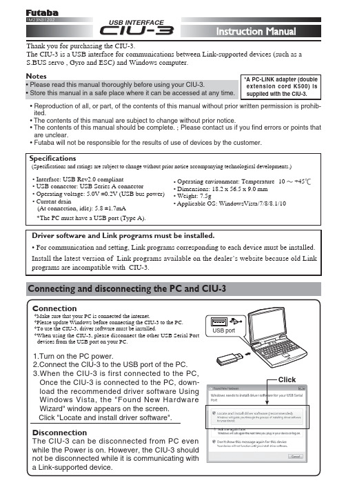
USB INTERFACEThank you for purchasing the CIU-3.The CIU-3 is a USB interface for communications between Link-supported devices (such as a S.BUS servo , Gyro and ESC) and Windows computer.Connecting and disconnecting the PC and CIU-3Driver software and Link programs must be installed.• For communication and setting, Link programs corresponding to each device must be installed.Install the latest version of Link programs available on the dealer’s website because old Link programs are incompatible with CIU-3.• Reproduction of all, or part, of the contents of this manual without prior written permission is prohib-ited.• The contents of this manual are subject to change without prior notice.• The contents of this manual should be complete. ; Please contact us if you find errors or points that are unclear.• Futaba will not be responsible for the results of use of devices by the customer.*A PC-LINK adapter (double extension cord K500) is supplied with the CIU-3.ClickExample of connection to Link programs supported device(The figure below is an example of connection to an S-BUS servo.)Usage Precautions<When requesting repair>Reread manual before requesting a repair. If the problem continues, contact your local Futaba dealer. (HCA's Service Center.)©FUT ABA CORPORA TION 2016,04 (1)FUTABA CORPORATION Phone: +81 475 32 6982, Facsimile: +81 475 32 69831080 Yabutsuka, Chosei-mura, Chosei-gun, Chiba 299-4395, Japan。
IBM Data Protector 内部数据库备份指南说明书

Internal database backup after the upgradeOld backups of the internal database created with dbtool.pl are not usable with Data Protector.You must configure a new backup specification to back up the internal database and configuration.See the online Help index:“IDB,configuring backups”.Apart from using a tape device,the IDB backup in Data Protector differs from Application Recovery Manager in the following details:•the Data Protector services are not stopped during the backup as with dbtool.pl•the VSS database is not backed upUpgrade of backup specificationsBackup specification in Application Recovery Manager do not contain tape devices.After theupgrade to Data Protector,the backup specifications can be used only for ZDB to disk.To use tape functionality(ZDB to disk+tape,ZDB to tape),you must reconfigure the backup specifications,specifying the tape device.Changes in omnib usageIf no options are specified,Data Protector defaults to ZDB to disk+tape.Application RecoveryManager backup sessions started from the CLI using the omnib command will therefore fail dueto missing tape devices.To keep your existing backup specifications without reconfiguring themfor ZDB to disk+tape,use the-disk_only option to run ZDB to disk.Upgrading from Solaris8to Solaris9If you have Data Protector6.20Disk Agent(DA)installed on Solaris8,and you want to upgrade the operating system to Solaris9,consider the impact of this upgrade on Data Protector.It isrecommended to replace the generic Solaris DA installed on the system with the Solaris9DA toensure proper operation of Data Protector and enable advanced backup options for Solaris9,such as backup of extended attributes.Perform the upgrade in the following sequence:1.Upgrade the operating system from Solaris8to Solaris9.For more information,see Solarisdocumentation.2.Remotely install the Disk Agent on the upgraded system using an Installation Server.This willreplace the generic Solaris Disk Agent with Solaris9Disk Agent.See“Remote installation”(page74)or the ob2install man page.Migrating from HP-UX11.x(PA-RISC)to HP-UX11.23/11.31(IA-64) This section describes the procedure for migrating your existing Cell Manager from a PA-RISCarchitecture based HP-UX11.x system to an HP-UX11.23/11.31system for the Intel Itanium2(IA-64)architecture.LimitationsFor details on supported operating system versions,platforms,processor architectures and DataProtector components as well as required patches,general limitations,and installation requirements, see the HP Data Protector Product Announcements,Software Notes,and References.•The migration is supported only from the Data Protector6.20Cell Manager on a PA-RISC based HP-UX11.x system.•For the supported combinations of MoM configurations,see“MoM specifics”(page177).Upgrading from Solaris8to Solaris9175Prerequisite•Before the migration,the Data Protector Cell Manager on a PA-RISC architecture based HP-UX11.x system must be upgraded to Data Protector6.20.LicensesThe new Cell Manager(IA-64system)will have a different IP address as the old Cell Manager,therefore you should apply for the licenses migration prior to the migration.For a limited amountof time,licenses on both system will be operational.If licenses are based on an IP range and the new Cell Manager’s IP address is within this range,no license reconfiguration is necessary.See“License migration to Data Protector6.20”(page205)for details.Migration procedurePerform the migration procedure as follows:1.Install a Data Protector client on the IA-64system and import it to the old Cell Manager’s cell.If you are planning to configure Data Protector in a cluster,install the client on the primarynode.See“Installing HP-UX clients”(page51).2.Run the following command on the old Cell Manager to add the hostname of the IA-64systemto the list of trusted hosts on secured clients:omnimigrate.pl -prepare_clients New_CM_Name,where the New_CM_Name is theclient name of the IA-64system from the previous step.For more information about trusted hosts and securing Data Protector clients,see“Securingclients”(page135)and“Host trusts”(page143).3.Back up the IDB.Make sure that the used media can later be accessed on the new CellManager system.See the online Help index:“IDB backup”.4.Restore the IDB to a temporary location on the IA-64system.See the online Help index:“IDBrestore”.5.Uninstall the Data Protector client from the IA-64system.See“Uninstalling a Data Protectorclient”(page146).6.Install Data Protector Cell Manager on the IA-64system.If you are planning to configure DataProtector in a cluster,install the Cell Manager on the primary node as a standalone CellManager(not cluster aware).See“Installing the Data Protector Cell Manager(CM)andInstallation Server(s)(IS)”(page26).7.If you changed the default Data Protector Inet port on the old Cell Manager,set the same Inetport also on the new Cell Manager.See“Changing the default Data Protector Inet port”(page230).8.Move the restored IDB(residing in a temporary location on the new Cell Manager),andconfiguration data to the same location on the new Cell Manager as it was on the old CellManager.See the online Help index:“IDB restore”.If the old Cell Manager was cluster-aware,comment out the SHARED_DISK_ROOT andCS_SERVICE_HOSTNAME variables in the /etc/opt/omni/server/sg/sg.conf file.This is necessary even if the new Cell Manager will be cluster-aware.9.To migrate the IDB and clients to the new Cell Manager,and to reconfigure the Cell Manager’ssettings,perform the following steps on the new Cell Manager:•If you want to configure a standalone IA-64Cell Manager,run the omnimigrate.pl -configure command.See the omnimigrate.pl man page.•If you want to configure a cluster-aware IA-64Cell Manager:176Upgrading to Data Protector6.20a.Run the omnimigrate -configure_idb command to configure the IDB from theold Cell Manager for use on the new Cell Manager.See the omnimigrate.plman page.b.Run the omnimigrate -configure_cm command to reconfigure the configurationdata transferred from the old Cell Manager for use on the new Cell Manager.Seethe omnimigrate.pl man page.c.Export the old virtual server from the cell by running the omnicc -export_hostOld_CM_Name.d.Configure the primary and secondary Cell Manager.See the online Help index:“MC/ServiceGuard integration configuring”.e.Run the omnimigrate -configure_clients command to migrate the clientsfrom the old Cell Manager to the new Cell Manager.Note that the old Cell Managerwill keep the clients in the configuration files although it will not be their Cell Manageranymore.NOTE:If the/etc/opt/omni/server directory is located on the shared clustervolume,the configuration changes made by the omnimigrate.pl script will affect allnodes in the cluster.NOTE:The old Cell Manager will automatically become a client in the new cell.You canuninstall the Cell Manager component from the old Cell Manager,because it is not necessaryanymore.See“Changing Data Protector software components”(page154).10.Configure the licenses on the new Cell Manager.See“Data Protector6.20product structureand licenses”(page203).11.Additional steps are required if the following is true:•Your cell is a part of the MoM environment.See“MoM specifics”(page177).•Your cell works across a firewall.Reconfigure all firewall related settings on the new Cell Manager.See the online Help index:“firewall environments”.•You want to have an Installation Server on your new Cell Manager.See“Installation Server specifics”(page178).MoM specificsIf the new Cell Manager will be configured in the MoM,additional steps are required after thebasic migration procedure has been completed.The required steps depend on the configurationof the MoM for the old and new Cell Managers in your environment.The supported combinations are:•The old Cell Manager was a MoM client;the new Cell Manager will be a MoM client of the same MoM Manager.Perform the following steps:1.On the MoM Manager,export the old Cell Manager from the MoM Manager cell andimport the new Cell Manager.See the online Help index:“client systems exporting”.2.Add the MoM administrator to the users list on the new Cell Manager.See the onlineHelp index:“MoM administrator,adding”.•The old Cell Manager was a MoM Manager;the new Cell Manager will be a MoM Manager.If the old MoM Manager was the only client in the MoM,no action is necessary.Otherwise,perform the following steps:1.On the old MoM Manager(the old Cell Manager),export all MoM clients.2.On the new MoM Manager(the new Cell Manager),import all MoM clients.3.Add the MoM administrator to the users list on all MoM clients.Migrating from HP-UX11.x(PA-RISC)to HP-UX11.23/11.31(IA-64)177。
XMODEM-YMODEM-Protocol-Refrence

XMODEM/YMODEM PROTOCOL REFERENCEA compendium of documents describing theXMODEM and YMODEMFile Transfer ProtocolsThis document was formatted8-4-87.Edited by Chuck ForsbergPlease distribute as widely as possible.Questions to Chuck ForsbergOmen Technology IncThe High Reliability Software17505-V Sauvie Island RoadPortland Oregon97231VOICE:503-621-3406:VOICEModem(TeleGodzilla):503-621-3746Speed19200,2400,1200,300CompuServe:70007,2304GEnie:CAFUUCP:...!tektronix!reed!omen!caf1.TOWER OF BABEL (4)1.1Definitions (4)2.YMODEM MINIMUM REQUIREMENTS (6)3.WHY YMODEM? (7)3.1Some Messages from the Pioneer (8)4.XMODEM PROTOCOL ENHANCEMENTS (10)4.1Graceful Abort (10)4.2CRC-16Option (10)4.3XMODEM-1k1024Byte Block (11)5.YMODEM Batch File Transmission (13)5.1KMD/IMP Exceptions to YMODEM (17)6.YMODEM-g File Transmission (18)7.XMODEM PROTOCOL OVERVIEW (19)7.1Definitions (19)7.2Transmission Medium Level Protocol (19)7.3File Level Protocol (20)7.3.1Common_to_Both_Sender_and_Receiver (20)7.3.2Receive_Program_Considerations (20)7.3.3Sending_program_considerations (21)7.4Programming Tips (22)8.XMODEM/CRC Overview (23)8.1CRC Calculation (24)8.1.1Formal_Definition (24)8.2CRC File Level Protocol Changes (25)8.2.1Common_to_Both_Sender_and_Receiver (25)8.2.2Receive_Program_Considerations (25)8.2.3Sending_Program_Considerations (26)8.3Data Flow Examples with CRC Option (26)9.MORE INFORMATION (28)9.1TeleGodzilla Bulletin Board (28)9.2Unix UUCP Access (28)10.REVISIONS (29)11.YMODEM Programs (30)Figure1XMODEM-1k Blocks (12)Figure2Mixed1024and128byte Blocks (12)Figure3YMODEM Batch Transmission Session (15)Figure4YMODEM Batch Transmission Session-1k Blocks (16)Figure5YMODEM Filename block transmitted by sz (16)Figure6YMODEM Header Information and Features (16)Figure7YMODEM-g Transmission Session (18)Figure8XMODEM Message Block Level Protocol (20)Figure9Data flow including Error Recovery (21)Figure10Message Block Level Protocol,CRC mode (23)Figure11Example of CRC Calculation written in C (24)Figure12Data Flow:Receiver has CRC Option,Sender Doesn't (26)Figure13Receiver and Sender Both have CRC Option (27)1.Tower Of BabelA"YMODEM Tower of Babel"has descended on the microcomputing community bringing with it confusion,frustration,bloated phone bills,and wasted man hours.Sadly,I(Chuck Forsberg)am partly to blame for this mess.As author of the early1980s batch and1k XMODEM extensions,I assumed readers of earlier versions of this document would implement as much of the YMODEM protocol as their programming skills and computing environments would permit.This proved a rather naive assumption as programmers motivated by competitive pressure implemented as little of YMODEM as possible.Some have taken whatever parts of YMODEM that appealed to them, applied them to MODEM7Batch,Telink,XMODEM or whatever,and called the result YMODEM.Jeff Garbers(Crosstalk package development director)said it all:"With protocols in the public domain,anyone who wants to dink around with them can go ahead."1Documents containing altered examples derived from YMODEM.DOC have added to the confusion.In one instance,the heading in YMODEM.DOC's Figure1has mutated from"1024 byte Packets"to"YMODEM/CRC File Transfer Protocol".None of the XMODEM and YMODEM examples shown in one document were correct.To put an end to this confusion,we must make"perfectly clear"what YMODEM stands for,as Ward Christensen defined it in his1985coining of the term.To the majority of you who read,understood,and respected Ward's definition of YMODEM,I apologize for the inconvenience.1.1DefinitionsARC ARC is a program that compresses one or more files into an archive and extracts files from such archives.XMODEM refers to the file transfer etiquette introduced by Ward Christensen's1977 MODEM.ASM program.The name XMODEM comes from Keith Petersen's XMODEM.ASM program,an adaptation of MODEM.ASM for Remote CP/M(RCPM) systems.It's also called the MODEM or MODEM2protocol.Some who are unaware of MODEM7's unusual batch file mode call it MODEM7.Other aliases include"CP/M Users' Group"and"TERM II FTP3".The name XMODEM caught on partly because it is distinctive and partly because of media interest in bulletin board and RCPM systems where it was accessed with an"XMODEM"command.This protocol is supported by every serious communications program because of its universality,simplicity,and reasonable performance.XMODEM/CRC replaces XMODEM's1byte checksum with a two byte Cyclical Redundancy 1.Page C/12,PC-WEEK July12,1987Check(CRC-16),giving modern error detection protection.XMODEM-1k Refers to the XMODEM/CRC protocol with1024byte data blocks.YMODEM Refers to the XMODEM/CRC(optional1k blocks)protocol with batch transmission as described below.True YMODEM(TM)In an attempt to sort out the YMODEM Tower of Babel,Omen Technology has trademarked the term True YMODEM(TM)to represent the complete YMODEM protocol described in this document,including pathname,length,and modification date transmitted in block0.Please contact Omen Technology about certifying programs for True YMODEM(TM)compliance.ZMODEM uses familiar XMODEM/CRC and YMODEM technology in a new protocol that provides reliability,throughput,file management,and user amenities appropriate to contemporary data communications.ZOO Like ARC,ZOO is a program that compresses one or more files into a"zoo archive".ZOO supports many different operating systems including Unix and VMS.2.YMODEM Minimum RequirementsAll programs claiming to support YMODEM must meet the following minimum requirements:✓The sending program shall send the pathname(file name)in block0.✓The pathname shall be a null terminated ASCII string as described below.✓The receiving program shall use this pathname for the received file name,unless explicitly overridden.✓The sending program shall use CRC-16in response to a"C"pathname nak,otherwise use8 bit checksum.✓The receiving program must accept any mixture of128and1024byte blocks it receives.✓The sending program must not change the length of an unacknowledged block.✓At the end of each file,the sending program shall send EOT up to ten times until it receives an ACK character.(This is part of the XMODEM spec.)✓The end of a transfer session shall be signified by a null(empty)pathname.Programs not meeting all of these requirements are not YMODEM compatible.Meeting the minimum requirements does not guarantee reliable file transfers under stress.3.Why YMODEM?Since its development half a decade ago,the Ward Christensen modem protocol has enabled a wide variety of computer systems to interchange data.There is hardly a communications program that doesn't at least claim to support this protocol.Recent advances in computing,modems and networking have revealed a number of weaknesses in the original protocol:✓The short block length caused throughput to suffer when used with timesharing systems, packet switched networks,satellite circuits,and buffered(error correcting)modems.✓The8bit arithmetic checksum and other aspects allowed line impairments to interfere with dependable,accurate transfers.✓Only one file could be sent per command.The file name had to be given twice,first to the sending program and then again to the receiving program.✓The transmitted file could accumulate as many as127extraneous bytes.✓The modification date of the file was lost.✓A number of other protocols have been developed over the years,but none have displaced XMODEM to date:✓Lack of public domain documentation and example programs have kept proprietary protocols such as Blast,Relay,and others tightly bound to the fortunes of their suppliers.✓Complexity discourages the widespread application of BISYNC,SDLC,HDLC,X.25,and X.PC protocols.✓Performance compromises and complexity have limited the popularity of the Kermit protocol, which was developed to allow file transfers in environments hostile to XMODEM.The XMODEM protocol extensions and YMODEM Batch address some of these weaknesses while maintaining most of XMODEM's simplicity.YMODEM is supported by the public domain programs YAM(CP/M),YAM(CP/M-86),YAM(CCPM-86),IMP(CP/M),KMD(CP/M),rz/sz (Unix,Xenix,VMS,Berkeley Unix,Venix,Xenix,Coherent,IDRIS,Regulus).Commercial implementations include MIRROR,and Professional-YAM.1Communications programs supporting these extensions have been in use since1981.The1k block length(XMODEM-1k)described below may be used in conjunction with YMODEM Batch Protocol,or with single file transfers identical to the XMODEM/CRC protocol except for minimal changes to support1k blocks.Another extension is the YMODEM-g protocol.YMODEM-g provides maximum throughput when used with end to end error correcting media,such as X.PC and error correcting modems, including9600bps units by TeleBit,U.S.Robotics,Hayes,Electronic Vaults,Data Race,and1Available for IBM PC,XT,AT,Unix and Xenixothers.To complete this tome,edited versions of Ward Christensen's original protocol document and John Byrns's CRC-16document are included for reference.References to the MODEM or MODEM7protocol have been changed to XMODEM to accommodate the vernacular.In Australia,it is properly called the Christensen Protocol.3.1Some Messages from the Pioneer#:130940S0/Communications25-Apr-8518:38:47Sb:my protocolFm:Ward Christensen76703,3021To:allBe aware the article2DID quote me correctly in terms of the phrases like"not robust",etc.It was a quick hack I threw together,very unplanned(like everything I do),to satisfy a personal need to communicate with"some other"people.ONLY the fact that it was done in8/77,and that I put it in the public domain immediately,made it become the standard that it is.I think its time for me to(1)document it;(people call me and say"my product is going to include it-what can I 'reference'",or"I'm writing a paper on it,what do I put in the bibliography")and(2)propose an"incremental extension"to it,which might take"exactly"the form of Chuck Forsberg's YAM protocol.He wrote YAM in C for CP/M and put it in the public domain,and wrote a batch protocol for Unix3called rb and sb(receive batch,send batch),which was basically XMODEM with(a)a record0containing filename date time and size(b)a1K block size option(c)CRC-16.He did some clever programming to detect false ACK or EOT,but basically left them the same.People who suggest I make SIGNIFICANT changes to the protocol,such as"full duplex", "multiple outstanding blocks","multiple destinations",etc etc don't understand that the incredible simplicity of the protocol is one of the reasons it survived to this day in as many machines and programs as it may be found in!1Edited for typesetting appearance2Infoworld April29p.163VAX/VMS versions of these programs are also available.Consider the PC-NET group back in'77or so-documenting to beat the band-THEY had a protocol,but it was"extremely complex",because it tried to be"all things to all people"-i.e.send binary files on a7-bit system,etc.I was not that"benevolent".I(emphasize>I<)had an8-bit UART,so"my protocol was an8-bit protocol",and I would just say"sorry"to people who were held back by7-bit limitations....Block size:Chuck Forsberg created an extension of my protocol,called YAM,which is also supported via his public domain programs for UNIX called rb and sb-receive batch and send batch.They cleverly send a"block0"which contains the filename,date,time,and size.Unfortunately,its UNIX style,and is a bit weird1-octal numbers,etc.BUT,it is a nice way to overcome the kludgy"echo the chars of the name"introduced with MODEM7.Further,chuck uses CRC-16and optional1K blocks.Thus the record0,1K,and CRC, make it a"pretty slick new protocol"which is not significantly different from my own.Also,there is a catchy name-YMODEM.That means to some that it is the"next thing after XMODEM",and to others that it is the Y(am)MODEM protocol.I don't want to emphasize that too much-out of fear that other mfgrs might think it is a"competitive"protocol,rather than an "unaffiliated"protocol.Chuck is currently selling a much-enhanced version of his CP/M-80C program YAM,calling it Professional Yam,and its for the PC-I'm using it right now.VERY slick! 32K capture buffer,script,scrolling,previously captured text search,plus built-in commands for just about everything-directory(sorted every which way),XMODEM,YMODEM,KERMIT, and ASCII file upload/download,etc.You can program it to"behave"with most any system-for example when trying a number for CIS it detects the"busy"string back from the modem and substitutes a diff phone#into the dialing string and branches back to try it.1The file length,time,and file mode are optional.The pathname and file length may be sent alone if desired.4.XMODEM Protocol EnhancementsThis chapter discusses the protocol extensions to Ward Christensen's1982XMODEM protocol description document.The original document recommends the user be asked whether to continue trying or abort after10 retries.Most programs no longer ask the operator whether he wishes to keep retrying.Virtually all correctable errors are corrected within the first few retransmissions.If the line is so bad that ten attempts are insufficient,there is a significant danger of undetected errors.If the connection is that bad,it's better to redial for a better connection,or mail a floppy disk.4.1Graceful AbortThe YAM and Professional-YAM X/YMODEM routines recognize a sequence of two consecutive CAN(Hex18)characters without modem errors(overrun,framing,etc.)as a transfer abort command.This sequence is recognized when is waiting for the beginning of a block or for an acknowledgement to a block that has been sent.The check for two consecutive CAN characters reduces the number of transfers aborted by line hits.YAM sends eight CAN characters when it aborts an XMODEM,YMODEM,or ZMODEM protocol file transfer.Pro-YAM then sends eight backspaces to delete the CAN characters from the remote's keyboard input buffer,in case the remote had already aborted the transfer and was awaiting a keyboarded command.4.2CRC-16OptionThe XMODEM protocol uses an optional two character CRC-16instead of the one character arithmetic checksum used by the original protocol and by most commercial implementations. CRC-16guarantees detection of all single and double bit errors,all errors with an odd number of error bits,all burst errors of length16or less,99.9969%of all17-bit error bursts,and99.9984per cent of all possible longer error bursts.By contrast,a double bit error,or a burst error of9bits or more can sneak past the XMODEM protocol arithmetic checksum.The XMODEM/CRC protocol is similar to the XMODEM protocol,except that the receiver specifies CRC-16by sending C(Hex43)instead of NAK when requesting the FIRST block.A two byte CRC is sent in place of the one byte arithmetic checksum.YAM's c option to the r command enables CRC-16in single file reception,corresponding to the original implementation in the MODEM7series programs.This remains the default because many commercial communications programs and bulletin board systems still do not support CRC-16, especially those written in Basic or Pascal.XMODEM protocol with CRC is accurate provided both sender and receiver Enhancements both report a successful transmission.The protocol is robust in the presence of characters lost by buffer overloading on timesharing systems.The single character ACK/NAK responses generated by the receiving program adapt well to split speed modems,where the reverse channel is limited to ten per cent or less of the main channel's speed.XMODEM and YMODEM are half duplex protocols which do not attempt to transmit information and control signals in both directions at the same time.This avoids buffer overrun problems that have been reported by users attempting to exploit full duplex asynchronous file transfer protocols such as Blast.Professional-YAM adds several proprietary logic enhancements to XMODEM's error detection and recovery.These compatible enhancements eliminate most of the bad file transfers other programs make when using the XMODEM protocol under less than ideal conditions.4.3XMODEM-1k1024Byte BlockDisappointing throughput downloading from Unix with YMODEM1lead to the development of 1024byte blocks in1982.1024byte blocks reduce the effect of delays from timesharing systems, modems,and packet switched networks on throughput by87.5per cent in addition to decreasing XMODEM's per byte overhead3per cent on long files.The choice to use1024byte blocks is expressed to the sending program on its command line or selection menu.21024byte blocks improve throughput in many applications,but some environments cannot accept1024byte bursts,especially minicomputers running19.2kb ports.An STX(02)replaces the SOH(01)at the beginning of the transmitted block to notify the receiver of the longer block length.The transmitted block contains1024bytes of data.The receiver should be able to accept any mixture of128and1024byte blocks.The block number(in the second and third bytes of the block)is incremented by one for each block regardless of the block length.The sender must not change between128and1024byte block lengths if it has not received a valid ACK for the current block.Failure to observe this restriction allows transmission errors to pass undetected.If1024byte blocks are being used,it is possible for a file to"grow"up to the next multiple of 1024bytes.This does not waste disk space if the allocation granularity is1k or greater.With YMODEM batch transmission,the optional file length transmitted in the file name block allows the receiver to discard the padding,preserving the exact file length and contents.1024byte blocks may be used with batch file transmission or with single file transmission. CRC-16should be used with the k option to preserve data integrity over phone lines.If a program wishes to enforce this recommendation,it should cancel the transfer,then issue an informative diagnostic message if the receiver requests checksum instead of CRC-16.Under no circumstances may a sending program use CRC-16unless the receiver commands CRC-16.1The name hadn't been coined yet,but the protocol was the same.2See"KMD/IMP Exceptions to YMODEM"below.Figure1XMODEM-1k BlocksSENDER RECEIVER"s-k foo.bar" "foo.bar open x.x minutes"CSTX01FE Data[1024]CRC CRCACKSTX02FD Data[1024]CRC CRCACKSTX03FC Data[1000]CPMEOF[24]CRC CRCACKEOTACKFigure2Mixed1024and128byte BlocksSENDER RECEIVER"s-k foo.bar" "foo.bar open x.x minutes"CSTX01FE Data[1024]CRC CRCACKSTX02FD Data[1024]CRC CRCACKSOH03FC Data[128]CRC CRCACKSOH04FB Data[100]CPMEOF[28]CRC CRCACKEOTACK5.YMODEM Batch File TransmissionThe YMODEM Batch protocol is an extension to the XMODEM/CRC protocol that allows0or more files to be transmitted with a single command.(Zero files may be sent if none of the requested files is accessible.)The design approach of the YMODEM Batch protocol is to use the normal routines for sending and receiving XMODEM blocks in a layered fashion similar to packet switching methods.Why was it necessary to design a new batch protocol when one already existed in MODEM7?1 The batch file mode used by MODEM7is unsuitable because it does not permit full pathnames, file length,file date,or other attribute information to be transmitted.Such a restrictive design, hastily implemented with only CP/M in mind,would not have permitted extensions to current areas of personal computing such as Unix,DOS,and object oriented systems.In addition,the MODEM7batch file mode is somewhat susceptible to transmission impairments.As in the case of single a file transfer,the receiver initiates batch file transmission by sending a "C"character(for CRC-16).The sender opens the first file and sends block number0with the following information.2Only the pathname(file name)part is required for batch transfers.To maintain upwards compatibility,all unused bytes in block0must be set to null.Pathname The pathname(conventionally,the file name)is sent as a null terminated ASCII string. This is the filename format used by the handle oriented MSDOS(TM)functions and C library fopen functions.An assembly language example follows:DB'foo.bar',0No spaces are included in the pathname.Normally only the file name stem(no directory prefix)is transmitted unless the sender has selected YAM's f option to send the full pathname.The source drive(A:,B:,etc.)is not sent.Filename Considerations:✓File names are forced to lower case unless the sending system supports upper/lower case file names.This is a convenience for users of systems(such as Unix)which store filenames in upper and lower case.✓The receiver should accommodate file names in lower and upper case.✓When transmitting files between different operating systems,file names must be acceptable to both the sender and receiving operating systems.1The MODEM7batch protocol transmitted CP/M FCB bytes f1...f8and t1...t3one character at a time.The receiver echoed these bytes as received,one at a time.2Only the data part of the block is described here.If directories are included,they are delimited by/;i.e.,"subdir/foo"is acceptable,"subdir\foo"is not.Length The file length and each of the succeeding fields are optional.1The length field is stored in the block as a decimal string counting the number of data bytes in the file.The file length does not include any CPMEOF(^Z)or other garbage characters used to pad the last block.If the file being transmitted is growing during transmission,the length field should be set to at least the final expected file length,or not sent.The receiver stores the specified number of characters,discarding any padding added by the sender to fill up the last block.Modification Date The mod date is optional,and the filename and length may be sent without requiring the mod date to be sent.Iff the modification date is sent,a single space separates the modification date from the file length.The mod date is sent as an octal number giving the time the contents of the file were last changed, measured in seconds from Jan11970Universal Coordinated Time(GMT).A date of0implies the modification date is unknown and should be left as the date the file is received.This standard format was chosen to eliminate ambiguities arising from transfers between different time zones.Mode Iff the file mode is sent,a single space separates the file mode from the modification date. The file mode is stored as an octal string.Unless the file originated from a Unix system,the file mode is set to0.rb(1)checks the file mode for the0x8000bit which indicates a Unix type regular file.Files with the0x8000bit set are assumed to have been sent from another Unix(or similar) system which uses the same file conventions.Such files are not translated in any way.Serial Number Iff the serial number is sent,a single space separates the serial number from the file mode.The serial number of the transmitting program is stored as an octal string.Programs which do not have a serial number should omit this field,or set it to0.The receiver's use of this field is optional.Other Fields YMODEM was designed to allow additional header fields to be added as above without creating compatibility problems with older YMODEM programs.Please contact Omen Technology if other fields are needed for special application requirements.The rest of the block is set to nulls.This is essential to preserve upward compatibility.2If the filename block is received with a CRC or other error,a retransmission is requested.After the filename block has been received,it is ACK'ed if the write open is successful.If the file cannot be1Fields may not be skipped.2If,perchance,this information extends beyond128bytes(possible with Unix4.2BSD extended file names),the block should be sent as a1k block as described above.opened for writing,the receiver cancels the transfer with CAN characters as described above.The receiver then initiates transfer of the file contents according to the standard XMODEM/CRC protocol.After the file contents have been transmitted,the receiver again asks for the next pathname.Transmission of a null pathname terminates batch file transmission.Note that transmission of no files is not necessarily an error.This is possible if none of the files requested of the sender could be opened for reading.The YMODEM receiver requests CRC-16by default.The Unix programs sz(1)and rz(1)included in the source code file RZSZ.ZOO should answer other questions about YMODEM batch protocol.Figure3YMODEM Batch Transmission SessionSENDER RECEIVER"sb foo.*<CR>""sending in batch mode etc."C(command:rb)SOH00FF foo.c NUL[123]CRC CRCACKCSOH01FE Data[128]CRC CRCACKSOH03FC Data[128]CRC CRCACKSOH04FB Data[100]CPMEOF[28]CRC CRCACKEOTNAKEOTACKCSOH00FF NUL[128]CRC CRCACKFigure4YMODEM Batch Transmission Session-1k BlocksSENDER RECEIVER"sb foo.*<CR>" "sending in batch mode etc."C(command:rb)SOH00FF foo.c NUL[123]CRC CRCACKSTX02FD Data[1024]CRC CRCACKSOH03FC Data[128]CRC CRCACKSOH04FB Data[100]CPMEOF[28]CRC CRCACKEOTNAKEOTACKCSOH00FF NUL[128]CRC CRCACKFigure5YMODEM Filename block transmitted by sz-rw-r--r--6347Jun17198420:34bbcsched.txt000100FF62626373636865642E74787400|...bbcsched.txt.| 1036333437203333313437343235313320|63473314742513| 2031303036343400000000000000000000|100644..........| 3000000000000000000000000000000000 4000000000000000000000000000000000 5000000000000000000000000000000000 6000000000000000000000000000000000 700000000000000000000000000000000080000000CA56Figure6YMODEM Header Information and FeaturesProgram Length Date Mode S/N1k-Blk YMODEM-g Unix rz/sz yes yes yes no yes sb only VMS rb/sb yes no no no yes noPro-YAM yes yes no yes yes yesCP/M YAM no no no no yes noKMD/IMP?no no no yes no5.1KMD/IMP Exceptions to YMODEMKMD and IMP use a"CK"character sequence emitted by the receiver to trigger the use of1024 byte blocks as an alternative to specifying this option to the sending program.Although this two character sequence works well on single process micros in direct communication,timesharing systems and packet switched networks can separate the successive characters by several seconds, rendering this method unreliable.Sending programs may detect the CK sequence if the operating enviornment does not preclude reliable implementation.Instead of the standard YMODEM file length,KMD and IMP transmit the CP/M record count in the last two bytes of the header block.6.YMODEM-g File TransmissionDeveloping technology is providing phone line data transmission at ever higher speeds using very specialized techniques.These high speed modems,as well as session protocols such as X.PC, provide high speed,nearly error free communications at the expense of considerably increased delay time.This delay time is moderate compared to human interactions,but it cripples the throughput of most error correcting protocols.The g option to YMODEM has proven effective under these circumstances.The g option is driven by the receiver,which initiates the batch transfer by transmitting a G instead of C.When the sender recognizes the G,it bypasses the usual wait for an ACK to each transmitted block,sending succeeding blocks at full speed,subject to XOFF/XON or other flow control exerted by the medium.The sender expects an inital G to initiate the transmission of a particular file,and also expects an ACK on the EOT sent at the end of each file.This synchronization allows the receiver time to open and close files as necessary.If an error is detected in a YMODEM-g transfer,the receiver aborts the transfer with the multiple CAN abort sequence.The ZMODEM protocol should be used in applications that require both streaming throughput and error recovery.Figure7YMODEM-g Transmission SessionSENDER RECEIVER"sb foo.*<CR>""sending in batch mode etc."G(command:rb-g)SOH00FF foo.c NUL[123]CRC CRCGSOH01FE Data[128]CRC CRCSTX02FD Data[1024]CRC CRCSOH03FC Data[128]CRC CRCSOH04FB Data[100]CPMEOF[28]CRC CRCEOTACKGSOH00FF NUL[128]CRC CRC。
ARM_debug_interface_v5_supplement

2
2.1 2.2 2.3 2.4 2.5 2.6 2.7 2.8 2.9 2.10 2.11 2.12 2.13 2.14 2.15 2.16 2.17
ADIV5.0 ERRATA AND CLARIFICATIONS ........................................................................ 8
Proprietary notice
This ARM Architecture Reference Manual is protected by copyright and the practice or implementation of the information herein may be protected by one or more patents or pending applications. No part of this ARM Architecture Reference Manual may be reproduced in any form by any means without the express prior written permission of ARM. No license, express or implied, by estoppel or otherwise to any intellectual property rights is granted by this ARM Architecture Reference Manual. Your access to the information in this ARM Architecture Reference Manual is conditional upon your acceptance that you will not use or permit others to use the information for the purposes of determining whether implementations of the ARM architecture infringe any third party patents. This ARM Architecture Reference Manual is provided “as is”. ARM makes no representations or warranties, either express or implied, included but not limited to, warranties of merchantability, fitness for a particular purpose, or non-infringement, that the content of this ARM Architecture Reference Manual is suitable for any particular purpose or that any practice or implementation of the contents of the ARM Architecture Reference Manual will not infringe any third party patents, copyrights, trade secrets, or other rights. This ARM Architecture Reference Manual may include technical inaccuracies or typographical errors. To the extent not prohibited by law, in no event will ARM be liable for any damages, including without limitation any direct loss, lost revenue, lost profits or data, special, indirect, consequential, incidental or punitive damages, however caused and regardless of the theory of liability, arising out of or related to any furnishing, practicing, modifying or any use of this ARM Architecture Reference Manual, even if ARM has been advised of the possibility of such damages. Words and logos marked with ® or TM are registered trademarks or trademarks of ARM Limited, except as otherwise stated below in this proprietary notice. Other brands and names mentioned herein may be the trademarks of their respective owners. Copyright © 2009 ARM Limited 110 Fulbourn Road Cambridge, England CB1 9NJ Restricted Rights Legend: Use, duplication or disclosure by the United States Government is subject to the restrictions set forth in DFARS 252.227-7013 (c)(1)(ii) and FAR 52.227-19. This document is Non-Confidential but any disclosure by you is subject to you providing notice to and the acceptance by the recipient of, the conditions set out above.
SIMATIC Energy Manager PRO V7.2 - Operation Operat

2 Energy Manager PRO Client................................................................................................................. 19
2.1 2.1.1 2.1.2 2.1.3 2.1.4 2.1.5 2.1.5.1 2.1.5.2 2.1.6
Basics ................................................................................................................................ 19 Start Energy Manager ........................................................................................................ 19 Client as navigation tool..................................................................................................... 23 Basic configuration ............................................................................................................ 25 Search for object................................................................................................................ 31 Quicklinks.......................................................................................................................... 33 Create Quicklinks ............................................................................................................... 33 Editing Quicklinks .............................................................................................................. 35 Help .................................................................................................................................. 38
OKI DICOM嵌入式打印机负载均衡部署指南说明书

D E P L O Y M E N T G U I D E Load Balancing OKI DICOM-Embedded Printersv1.1.1Deployment GuideNOTE: This guide has been archived and is no longer being maintained. While the content is still valid for the particular software versions mentioned, it may refer to outdated software that has now reached end-of-life. For ****************************************************.Contents1. About this Guide (3)2. Appliances Supported (3)3. Software Versions Supported (3)4. OKI DICOM-Embedded Printer Software Versions Supported (3)5. OKI DICOM-Embedded Printer (4)6. Load Balancing OKI DICOM-Embedded Printers (4)Persistence (aka Server Affinity) (4)Port Requirements (4)Health Checks (4)7. Deployment Concept (5)Virtual Service (VIP) Requirements (5)8. Load Balancer Deployment Methods (6)Layer 7 SNAT Mode (6)Layer 4 SNAT Mode (7)Our Recommendation (8)9. Appliance – the Basics (9)Virtual Appliance Download & Deployment (9)Initial Network Configuration (9)Accessing the Web User Interface (WebUI) (9)HA Clustered Pair Configuration (11)10. Appliance Configuration for OKI DICOM-Embedded Printers – Using Layer 7 SNAT Mode (12)Configuring the Virtual Service (VIP) (12)Defining the Real Servers (RIPs) (12)Finalizing the Configuration (13)11. Appliance Configuration for OKI DICOM-Embedded Printers – Using Layer 4 SNAT Mode (13)Configuring the Virtual Service (VIP) (13)Defining the Real Servers (RIPs) (14)12. T esting & Verification (15)Running a T est Print (15)T est Print Failure (15)Using System Overview (16)13. T echnical Support (16)14. Further Documentation (16)15. Conclusion (16)16. Appendix (17)1 – Clustered Pair Configuration – Adding a Slave Unit (17)17. Document Revision History (20)1.About this GuideThis guide details the steps required to configure a load balanced OKI DICOM-embedded printer environment utilizing appliances. It covers the configuration of the load balancers and also any OKI DICOM-embedded printer configuration changes that are required to enable load balancing.For more information about initial appliance deployment, network configuration and using the Web User Interface (WebUI), please also refer to the relevant Administration Manual:•v7 Administration Manual•v8 Administration Manual Appliances SupportedAll our products can be used for load balancing OKI DICOM-embedded printers. The complete list of models is shown below:* For full specifications of these models please refer to: /products/hardware** Some features may not be supported, please check with support Software Versions Supported•V7.6.4 and later4.OKI DICOM-Embedded Printer Software Versions Supported•OKI DICOM-Embedded Printer – version 4.01 and later5.OKI DICOM-Embedded PrinterOKI’s range of DICOM-embedded printers allow for medical images to be printed directly from medical equipment. Printing directly from DICOM modalities eliminates the need to use conversion software or costly external hardware as part of the medical printing workflow. OKI’s printers can also be used for day-to-day printing tasks.Having a highly available print service allows printing to continue even when some printers are out of service, for example for maintenance. The load balancer will select a printer that is still online and ready to accept jobs and will send traffic there. Having a load balanced printing service also helps in a high volume printing environment, where multiple printers can share the printing load and increase the total pages per minute printing capacity. Overall, having a highly available print service improves the experience for physicians, medical professionals, and patients. appliances also support load balancing print servers, offering additional flexibility and possibilities for load balancing a full printing environment.6.Load Balancing OKI DICOM-Embedded PrintersNote: It's highly recommended that you have a working OKI DICOM-embedded printer environmentfirst before implementing the load balancer.Persistence (aka Server Affinity)OKI DICOM-embedded printers do not require session affinity at the load balancing layer.Port RequirementsOne port needs to be load balanced:Health ChecksIt is recommended to use the DICOM specific health check when load balancing DICOM printers. This can be found on the load balancer by setting Health Checks to External script and then setting Check Script to the DICOM-C-ECHO health check.7.Deployment ConceptVIPs = V irtual IP AddressesVirtual Service (VIP) RequirementsOne virtual service is needed in this deployment, which load balances the DICOM printer traffic.8.Load Balancer Deployment MethodsThe load balancer can be deployed in 4 fundamental ways: Layer 4 DR mode, Layer 4 NAT mode, Layer 4 SNAT mode, and Layer 7 SNAT mode.For OKI DICOM-embedded printers, using layer 7 SNAT mode is recommended. It is also possible to use layer 4 SNAT mode.These modes are described below and are used for the configurations presented in this guide. For configuring using layer 7 SNAT mode please refer to the section starting on page 12, and for configuring using layer 4 SNAT mode please refer to the section starting on page 13.Layer 7 SNAT ModeLayer 7 SNAT mode uses a proxy (HAProxy) at the application layer. Inbound requests are terminated on the load balancer, and HAProxy generates a new request to the chosen Real Server. As a result, Layer 7 is a slower technique than DR or NAT mode at Layer 4. Layer 7 is typically chosen when either enhanced options such as SSL termination, cookie based persistence, URL rewriting, header insertion/deletion etc. are required, or when the network topology prohibits the use of the layer 4 methods.This mode can be deployed in a one-arm or two-arm configuration and does not require any changes to the Real Servers. However, since the load balancer is acting as a full proxy it doesn't have the same raw throughput as the layer 4 methods.The load balancer proxies the application traffic to the servers so that the source of all traffic becomes the load balancer.•SNAT mode is a full proxy and therefore load balanced Real Servers do not need to be changed in any way •Because SNAT mode is a full proxy any server in the cluster can be on any accessible subnet including across the Internet or WAN•SNAT mode is not transparent by default, i.e. the Real Servers will not see the source IP address of the client,they will see the load balancers own IP address by default, or any other local appliance IP address if preferred(e.g. the VIP address), this can be configured per layer 7 VIP. If required, the clients IP address can be passedthrough either by enabling TProxy on the load balancer, or for HTTP, using X-forwarded-For headers. Please refer to chapter 6 in the administration manual for more details•SNAT mode can be deployed using either a 1-arm or 2-arm configuration•You should not use the same RIP:PORT combination for layer 7 SNAT mode VIPs and layer 4 SNAT mode VIPs because the required firewall rules conflict.Layer 4 SNAT ModeLayer 4 SNAT mode is a high performance solution, although not as fast as the other layer 4 modes.•The load balancer translates all requests from the external Virtual Service to the internal Real Servers in the same way as NAT mode (please refer to the previous page for details).•Layer 4 SNAT mode is not transparent, an iptables SNAT rule translates the source IP address to be the load balancer rather than the original client IP address.•Layer 4 SNAT mode can be deployed using either a one-arm or two-arm configuration.•For two-arm deployments, eth0 is normally used for the internal network and eth1 is used for the external network although this is not mandatory. If the Real Servers require Internet access, Autonat should be enabled using the WebUI option: Cluster Configuration > Layer 4 – Advanced Configuration, the external interfaceshould be selected.•Port translation is not possible in layer 4 SNAT mode i.e. having a different RIP port than the VIP port.•You should not use the same RIP:PORT combination for layer 7 SNAT mode VIPs and layer 4 SNAT mode VIPs because the required firewall rules conflict.Our RecommendationWhere possible, we recommend that layer 7 SNAT mode is used. This mode is simple to implement, and requires no changes to be made to any network architecture or servers. Ultimately, the final choice does depend on your specific requirements and infrastructure.Layer 4 SNAT mode can also be used as an alternative to layer 7 SNAT mode. Appliance – the BasicsVirtual Appliance Download & DeploymentA fully featured, fully supported 30 day trial is available if you are conducting a PoC (Proof of Concept) deployment. The VA is currently available for VMware, Virtual Box, Hyper-V, KVM and XEN and has been optimized for each Hypervisor. By default, the VA is allocated 1 CPU, 2GB of RAM and has an 8GB virtual disk. The Virtual Appliance can be downloaded here.Note: The same download is used for the licensed product, the only difference is that a license key file(supplied by our sales team when the product is purchased) must be applied using the appliance'sWebUI.Initial Network ConfigurationThe IP address, subnet mask, default gateway and DNS settings can be configured in several ways as detailed below:Method 1 - Using the Network Setup Wizard at the consoleAfter boot up, follow the instructions on the console to configure the IP address, subnet mask, default gateway and DNS settings.Method 2 - Using the WebUIUsing a browser, connect to the WebUI on the default IP address/port: https://192.168.2.21:9443T o set the IP address & subnet mask, use: Local Configuration > Network Interface ConfigurationT o set the default gateway, use: Local Configuration > RoutingT o configure DNS settings, use: Local Configuration > Hostname & DNSAccessing the Web User Interface (WebUI)The WebUI can be accessed via HTTPS at the following URL: https://192.168.2.21:9443/lbadmin* Note the port number →9443(replace 192.168.2.21 with the IP address of your load balancer if it's been changed from the default)Login using the following credentials:Username: loadbalancerPassword: loadbalancerNote: T o change the password , use the WebUI menu option: Maintenance > Passwords. Once logged in, the WebUI will be displayed as shown on the following page:(shows v8.2.x)HA Clustered Pair Configuration recommend that load balancer appliances are deployed in pairs for high availability. In this guide a single unit is deployed first, adding a secondary slave unit is covered in section 1 of the appendix on page 17.10.Appliance Configuration for OKI DICOM-Embedded Printers – Using Layer 7SNAT ModeNote: You should not use the same RIP:PORT combination for layer 7 SNAT mode VIPs and layer 4SNAT mode VIPs because the required firewall rules conflict.In the context of load balancing OKI DICOM-embedded printers, one load balancing method shouldbe chosen and stuck to. Mixing layer 7 and layer 4 SNAT modes is not advisable.Configuring the Virtual Service (VIP)ing the web user interface, navigate to Cluster Configuration > Layer 7 – Virtual Services and click on Add anew Virtual Service2.Define the Label for the virtual service as required, e.g. DICOM-Print3.Set the Virtual Service IP Address field to the required IP address, e.g. 192.168.85.1904.Set the Ports field to 111125.Set the Layer 7 Protocol to TCP Mode6.Click Update to create the virtual service7.Click Modfiy next to the newly created VIP8.Set Persistence Mode to None9.From the Health Checks drop-down list select External script10.From the Check Script drop-down list that appears, select DICOM-C-ECHO11.Click Update to apply the changesDefining The Real Servers (RIPs)ing the web user interface, navigate to Cluster Configuration > Layer 7 – Real Servers and click on Add a newReal Server next to the newly created VIP2.Define the Label for the real server as required, e.g. OKI-DICOM-Printer-13.Set the Real Server IP Address field to the required IP address, e.g. 192.168.85.2004.Set the Real Server Port to 111125.Click Update6.Repeat these steps to add additional real servers as requiredFinalizing the ConfigurationT o apply the new settings, HAProxy must be reloaded as follows:ing the WebUI, navigate to: Maintenance > Restart Services and click Reload HAProxy11.Appliance Configuration for OKI DICOM-Embedded Printers – Using Layer 4SNAT ModeNote: You should not use the same RIP:PORT combination for layer 4 SNAT mode VIPs and layer 7SNAT mode VIPs because the required firewall rules conflict.In the context of load balancing OKI DICOM-embedded printers, one load balancing method shouldbe chosen and stuck to. Mixing layer 4 and layer 7 SNAT modes is not advisable.Configuring the Virtual Service (VIP)ing the web user interface, navigate to Cluster Configuration > Layer 4 – Virtual Services and click on Add anew Virtual Service2.Define the Label for the virtual service as required, e.g. DICOM-Print3.Set the Virtual Service IP Address field to the required IP address, e.g. 192.168.85.1704.Set the Ports field to 111125.Set the Protocol set to TCP6.Set the Forwarding Method set to SNAT7.Click Update to create the virtual service8.Click Modfiy next to the newly created VIP9.Make sure that the Persistent checkbox is not checked10.From the Health Checks Check Type drop-down list select External script11.From the External script drop-down list that appears, select DICOM-C-ECHO12.Click Update to apply the changesDefining the Real Servers (RIPs)ing the web user interface, navigate to Cluster Configuration > Layer 4 – Real Servers and click on Add a newReal Server next to the newly created VIP2.Define the Label for the real server as required, e.g. OKI-DICOM-Printer-13.Set the Real Server IP Address field to the required IP address, e.g. 192.168.85.2004.Set the Real Server Port to 111125.Click Update6.Repeat these steps to add additional real servers as required12.T esting & VerificationRunning a T est PrintAn easy way to test if a load balanced OKI DICOM-embedded printer service is working is to send a test print to the VIP address.If the test print works as intended then the virtual service is working correctly.T est Print FailureIf the test print fails, the following error message may be displayed:T roubleshooting1.Confirm that the load balancer can route to the real servers, i.e. the printers. An easy way to check this is toconfirm that the real servers are showing as ‘green’ and online on the System Overview page. If the servers are showing as ‘red’ then the load balancer cannot communicate with them, which may indicate a networking issue2.If the real servers are showing as online, the next thing to check is that the same RIP:PORT combination is notbeing used for a layer 7 SNAT mode VIP and a layer 4 SNAT mode VIP. The required firewall rules conflict insuch a scenarioUsing System OverviewThe System Overview can be viewed in the WebUI. It shows a graphical view of all VIPs & RIPs (i.e. the OKI DICOM-embedded printers) and shows the state/health of each server as well as the state of the cluster as a whole. The example below shows that all three OKI DICOM-embedded printers are healthy and available to accept connections.13.T echnical SupportFor more details about configuring the appliance and assistance with designing your deployment please don't hesitate to contact the support team using the following email address: ************************14.Further DocumentationThe Administration Manual contains much more information about configuring and deploying the appliance. It's available here: /loadbalanceradministrationv8.pdf15.Conclusion appliances provide a very cost effective solution for highly available load balanced OKI DICOM-embedded printer environments.16.Appendix1 – Clustered Pair Configuration – Adding a Slave UnitIf you initially configured just the master unit and now need to add a slave - our recommended procedure, please refer to the relevant section below for more details:Note: A number of settings are not replicated as part of the master/slave pairing process andtherefore must be manually configured on the slave appliance. These are listed below:•Hostname & DNS settings•Network settings including IP addresses, bonding configuration and VLANs•Routing configuration including default gateways and static routes•Date & time settings•Physical – Advanced Configuration settings including Internet Proxy IP address & port, Firewalltable size, SMTP relay and Syslog server•SNMP settings•Graphing settings•Firewall Script & Firewall Lockdown Script settings•Software updatesVersion 7:Please refer to Chapter 8 – Appliance Clustering for HA in the v7 Administration Manual.Version 8:T o add a slave node – i.e. create a highly available clustered pair:•Deploy a second appliance that will be the slave and configure initial network settings•Using the WebUI, navigate to: Cluster Configuration > High-Availability Configuration•Specify the IP address and the loadbalancer users password (the default is 'loadbalancer') for the slave (peer) appliance as shown above•Click Add new node•The pairing process now commences as shown below:•Once complete, the following will be displayed:•T o finalize the configuration, restart heartbeat and any other services as prompted in the blue message box at the top of the screenNote: Clicking the Restart Heartbeat button on the master appliance will also automatically restart heartbeat on the slave appliance.17.Document Revision HistoryAbout ’s mission is to ensure that its clients’ businesses are never interrupted. The load balancer experts ask the right questions to get to the heart of what matters, bringing a depth of understanding to each deployment. Experience enables engineers to design less complex, unbreakable solutions - andto provide exceptional personalized support.United Kingdom pass House, North Harbour Business Park, Portsmouth, PO6 4PS UK:+44 (0) 330 380 1064********************************************** Canada Appliances Ltd.300-422 Richards Street, Vancouver,BC, V6B 2Z4, CanadaTEL:+1 866 998 0508**********************************************United States , Inc.4550 Linden Hill Road, Suite 201Wilmington, DE 19808, USA TEL: +1 833.274.2566**********************************************Germany GmbHT engstraße 2780798,München, GermanyTEL: +49 (0)89 2000 2179**********************************************© Copyright • 。
virtualbox protocol error
virtualbox protocol error英文版VirtualBox Protocol ErrorIn the realm of virtualization technology, VirtualBox stands as a popular and dependable tool. However, users may encounter various issues while using it, one such common problem being the "VirtualBox Protocol Error".This error typically occurs when there is a mismatch between the client and server versions of VirtualBox. The protocol used by VirtualBox for communication between the host and the virtual machines is specific, and any discrepancy in the versions can lead to this error.To resolve this issue, the first step is to ensure that both the client and the server are running the same version of VirtualBox. Updating both to the latest version is often recommended as it ensures compatibility and addresses any known issues.If updating the software does not resolve the problem, it could be due to corrupted installation files or a conflict with other software installed on the system. In such cases, reinstalling VirtualBox or uninstalling conflicting software may be necessary.Additionally, checking the system logs for any related errors can provide valuable insights into the cause of the problem. These logs can often be accessed through the event viewer or the terminal, depending on the operating system being used.In summary, the "VirtualBox Protocol Error" is often caused by version mismatches or corrupted installations. Keeping the software updated, reinstalling if necessary, and reviewing system logs are effective troubleshooting steps to resolve this issue.中文版VirtualBox协议错误在虚拟化技术领域,VirtualBox是一款流行且可靠的工具。
DellCommandUpdat...
DellCommandUpdat...This Universal Windows Platform (UWP) package contains the Dell Command Update for systems running the Windows 10 build 14393 (Redstone 1) or later. Dell Command Update is a stand-alone application for client systems, that provides updates for system software that is released by Dell. This application simplifies the BIOS, firmware, driver, and application update experience for Dell client hardware.补丁和增强功能- Added ADR functionality to support the DUP files- Enabling security enhancement with Dell signature verification for all packages.- Added one hour quiet period where no updates happen automatically when you start your new system for the first time. This feature helps to enhance the Out of Box Experience (OOBE). 版本版本4.3.0、A00类别系统管理发布日期29 7月 2021重要性推荐可用格式文件格式:面向MS Windows(32位)的更新包文件名:Dell-Command-Update-Application-for-Windows-10_GRVPK_WIN_4.3.0_A00_02.EXE下载类型: HTTP文件大小: 28.63 MB格式说明:Microsoft Windows 32位格式中的戴尔更新包(DUP)设计为可以在Microsoft Windows 64位操作系统上运行。
防火墙简介-防护边界安全1

As enterprises grow, corporate networks will most likely be growing to support this expansion. As growth occurs, so do security risks. Expansion of your enterprise's Internet and mobile computing infrastructure will result in an increased number of access points to privileged corporate data. Every access point represents a possible vulnerability that may be exploited to gain unauthorized entry into the newly expanded network. Knowledge of the access points, and how these must be configured to protect the enterprise's intellectual, commercial and proprietary assets from hackers, competitors, and electronic vandals is an essentialpre-requisite to enabling the enterprise to continue to operate in a safe and productive manner.企業在成長過程中,企業網路多半會因應成長而擴展。
在擴展的同時也會帶來安全上的風險。
企業網路和行動商務基礎設施的擴張,會導致能夠接觸到機密企業資料的存取點變多。
- 1、下载文档前请自行甄别文档内容的完整性,平台不提供额外的编辑、内容补充、找答案等附加服务。
- 2、"仅部分预览"的文档,不可在线预览部分如存在完整性等问题,可反馈申请退款(可完整预览的文档不适用该条件!)。
- 3、如文档侵犯您的权益,请联系客服反馈,我们会尽快为您处理(人工客服工作时间:9:00-18:30)。
A QKD Protocol Extendable to Support Entanglement and Reduce Unauthorized Information Gain by Randomizing the Bases Lists with Key Values and Invalidate ExplicitPrivacy AmplificationSrinivasan N, Sanjeevakumar C, Kasi Rajan M, Sudarsan L, Venkatesh R Department of Information Technology, Madras Institute of Technology, Chennai 600044Email : ns@AbstractThis paper suggests an improvement to the BB84 scheme in Quantum key distribution. The original scheme has its weakness in letting quantifiably more information gain to an eavesdropper during public announcement of unencrypted bases lists. The security of the secret key comes at the expense of the final key length. We aim at exploiting the randomness of preparation (measurement) basis and the bit values encoded (observed), so as to randomize the bases lists before they are communicated over the public channel. A proof of security is given for our scheme and proven that our protocol results in lesser information gain by Eve in comparison with BB84 and its other extensions. Moreover, an analysis is made on the feasibility of our proposal as such and to support entanglement based QKD. The performance of our protocol is compared in terms of the upper and lower bounds on the tolerable bit error rate. We also quantify the information gain (by Eve) mathematically using the familiar approach of the concept of Shannon’s entropy. The paper models the attack by Eve in terms of interference in a multi-access quantum channel. Besides, this paper also hints at the invalidation of a separate privacy amplification step in the "prepare-and-measure" protocols in general. Index TermsQuantum information, quantum cryptography, key distribution, entanglement.l. IntroductionThe framework for quantum cryptography essentially lies in the hands of nature [6]. Unless the laws of nature break, the security of the QKD schemes is assured. The most important axioms of quantum mechanics [12, 13, 18] that facilitate this idea are the uncertainty principle, quantum entanglement, teleportation and quantum measurement theory (whichis essentially Information gain vs. State disturbance).There are no physical means for gathering information about the identity of a quantum system's state when it is known to be prepared in oneof a set of non orthogonal states. This is because of the indistinguishability inherent among such states. This unique feature of quantum phenomena rests on the Hilbert space structure [16] along with the fact that time evolutions for isolated systems are unitary[14, 17, 18]. The uncertainty principle [12, 13, 18] explains the simultaneous measurability of observables (which are mathematicized as operators in Heisenberg mechanics). If two operators commute, they can be measured simultaneously, but non-commuting operators cannot be measured simultaneously. Thus, observables along orthogonal bases cannot be observed at the same time. Conscious observation of one will completely randomize the result in the other. Observation (practically measurement) of a quantum state has its effect in producing a tension between information gain and disturbance. In this paper, we shall quantitatively study the nature of this tension with respect to our protocol (which we refer to as randomization protocol henceforth). Of course, a theoretical description of our protocol is a mathematical idealization. Any real-life quantum cryptographic system is a complex physical system with many degrees of freedom, and is at best an approximation to the ideal protocol. Proving the security of any particular setup is a difficult task, requiring a detailed model of the apparatus. Even a seemingly minor and subtle omission can be fatal to the security of a cryptographic system.In designing a quantum crypt protocol, it is essential to prove its security under theoretical and practical considerations. Therefore, if one wants to model and analyze the cryptographic security of quantum protocols, one of the most basic questions to be answered is the following. What does it mean for twoquantum states to be “close” to each other or “far” apart? That is, we should be concerned with defining and relating various notions of “distance” between two quantum states. Formally a quantum state is nothing more than a square matrix of complex numbers that satisfies a certain set of supplementary properties. Because of this, any of the notions of distance between matrices that can be found in the mathematical literature would do for a quick fix. The only physical means available with which to distinguish two quantum states is that specified by the general notion of a quantum-mechanical measurement. We include, in this paper an analysis of our protocol by considering different distinguishability measures.All existing QKD schemes are variations to the fundamental BB84 protocol [2, 8]. In the BB84 protocol, Alice sends a qubit (i.e., a quantum bit or a two-level quantum system) in one of four states to Bob. The states 0and += (0and1)/2 and represent the classical bit 0, while the states and 1 and −=(0- +)/2 represent the bit 1. Alice chooses one of these four states uniformly at random, and sends it to Bob, who chooses randomly to measure in either the |0>, |1> basis (the “Z” basis) or the +,−basis (the “X” basis). Then, Alice and Bob announce the basis each of them used for each state (but not the actual state sent or measured in that basis), and discard any bits for which they used different bases. The remaining bits form the raw key, which will be processed some more to produce the final key.In the scheme as proposed by Hannes R Bohm et al [2], in addition to the lists of BB84, Alice and Bob both possess a preshared secret (randomizer) that is split into two parts, S-Alice and S-Bob. The information which basis was used during each individual measurement is encrypted before it is sent over the classical channel using the shared key. This is done by applying logic XOR between the list of bases and a part of the shared secret. This encryption of the encoding and measurement bases renders it impossible for a third party to correctly sift measurement results obtained from eavesdropping on the quantum channel. For the protocol to be secure it is mandatory that Alice and Bob use different parts of the shared secret and that for successive runs of the protocol, the secrecy of the shared secret has to be continuously refreshed. Our proposal has its roots in this scheme with the added benefit of invalidating explicit privacy amplification step and the randomizer need not be refreshed for every run of the protocol.The QKD scheme without public announcement of basis has been proposed by Won Young Hwang et al [1]. In this protocol, Alice and Bob share by any method (BB84 scheme) some secure binary random sequence that is known to nobody. This random sequence is to be used to determine the encoding basis u and u'. Alice (Bob) encodes (performs spin-measurement) on the basis z and x when it is 0 and 1, respectively. For example, when the bases random sequence is 0, 1, 1, 0, 1.....and the signal random sequence that Alice wants to send to Bob is1, 0, 1, 0, 1..... Then she sends to him the following quantum carriers−z, +x, −x, +z, −x,..... Since Alice and Bob have common random sequence, there will be perfect correlation between them unless the quantum carriers were perturbed by Eve or noise. Eve is naturally prevented from knowing about the encoding bases, since she does not know the bases sequence. As we see, public announcement of bases is not needed in the proposed scheme. However, the scheme can only be useful if it is possible to use safely the bases random sequence repeatedly. If this is not the case, Alice and Bob have to consume the same length of random sequences to obtain some length of new random sequences. Fortunately, quantum mechanical laws enable the bases random sequences to be used repeatedly enough.In the Inamori's Protocol [5]Alice and Bob are assumed to share initially a random string and the goal of QKD is to extend this string. Alice and Bob also choose a classical error-correcting code C1. Alice sends Bob a sequence of single photons as in either BB84 or the six-state scheme. They throw away all polarization data that are prepared in different bases and keep only the ones that are prepared in the same bases. They randomly select m of those pairs and perform a refined data analysis to find out the error rate of the various bases. Alice measures the remaining N-m =s particles to generate a random string. Being a random string, it generally has nontrivial error syndrome when regarded as a corrupted state of the codeword of C1. Alice transmits that error syndrome in an encrypted form to Bob. This is done by using a one-time pad encryption with (part of) the common string they initially share as the key. Bob corrects his error to recover the string. They discard all the bits where they disagree and keep only the ones where they agree. Finally,Alice and Bob perform privacy amplification on the remaining string to generate a secure string.One important class of protocols is the Entanglement Purification Protocol schemes for QKD [5, 8]. This is a generalized scheme and can be reduced to the standard BB84 and its extensions.Suppose Alice and Bob are connected by a noisy quantum channel (and perhaps also a noiseless classical channel). Entanglement purification provides a way of using the noisy quantum channel to simulatea noiseless one. More concretely, suppose Alice creates N EPR pairs and sends half of each pair to Bob. If the quantum communication channel between Alice and Bob is noisy (but stationary and memory-less), then Alice and Bob will share imperfect EPR pairs, each in the state P. They may attempt to apply local operations (including preparation of ancillary qubits, local unitary transformations, and measurements) and classical communications (LOCCs) to purify the N imperfect EPR pairs into a smaller number n, EPR pairs of high fidelity. This process is called an EPP. One way to classify EPPs isin terms of what type of classical communications they require: 'EPPs that can be implemented with only one-way classical communications from Alice to Bob, known as 1-EPPs' and 'EPPs requiring two-way classical communications, known as 2-EPPs'.Typically, a 1-EPP will consist of Alice measuringa series of commuting operators and sending the measurement result to Bob. Bob will then measure the same operators on his qubits. If there is no noise in the channel, Bob will get the same results as Alice, butof course when noise is present, some of the results will differ. From the algebraic structure of the list of operators measured, Bob can deduce the location and nature of the errors and correct them. Unfortunately, the process of measuring EPR pairs will have destroyed some of them, so the resulting state consistsof fewer EPR pairs than Alice sent.2-EPPs can be potentially more complex, but frequently have a similar structure. Again, Alice and Bob measure a set of identical operators. Then they compare their results, discard some EPR pairs, and together select a new set of operators to measure. An essential feature of a 2-EPP is that the subsequent choice of measurement operators may depend on the outcomes of previous measurements. This process continues for a while until the remaining EPR pairs have a low enough error rate for a 1-EPP to succeed. Then, a 1-EPP is applied.The proof of security of this class has been worked out already and its result is used for proving that our protocol is secure.In section II of our paper, the preliminary mathematical results and the basic notations used in the analysis of security considerations and information gain with respect to our protocol are discussed. In section III, we present a theoretical description of our protocol. In section IV, we analyze its security extensively and model all types of attacks by an eavesdropper. We quantify the information gain in the subsequent section. The final section includes a theoretical consideration of incorporating randomization into entanglement based QKD. 2. Mathematical Notations and Definitions This part enables the reader to understand the mathematical concepts and their notations used in quantum information processing [15, 19]. Much of the math given here will enable the reader to visualize the mathematical underpinnings given in our paper in support of our protocol.2.1. Operators in Quantum Theory with respect to Quantum CryptographyDensity operators are used for various purposes in quantum theory, and their significance depends somewhat on how they are used. Usually they function as pre-probabilities, i.e., they are devices for calculating quantum probabilities. Think of a density operator as something like a probability distribution in classical physics. The most common uses of a density operator are: to provide partial information about a system, in analogy with a probability distribution in classical physics (the operator ze kTH//−in statistical mechanics is an example), and to describe a subsystem of a total system made up of two (or more) parts.A density ρmatrix is a NN×matrix with unit trace that is Hermitian ()†.,.ρρ=e i and positive semi-definite 0.,.≥Ψψρe i for allΗ∈Ψ2.1.1. Quantum Ensembles. Suppose Alice is instructed to generate the quantum state jΨwith probability P j, and ship it to Bob in a closed box which is carefully isolated from the environment and keeps the quantum system isolated, so the dynamics is trivial.One speaks of a quantum ensemble {Pj,jΨ} . Here the jΨare assumed to be normalized, but they don't have to be orthogonal to each other. E.g., Alice sometimes prepares a qubit in state o, sometimes in state+, etc. The idea of an ensemble can be used even if one is only talking about one event, since it is just a method of visualizing probabilities. The unopened box is in front of Bob, who wonders whether this system "is in the state s," by which he means either in s or some state orthogonal to s; the corresponding sample space is{][],[SIS−, where[]s sS=. Bob reasons as follows. If Aliceprepared j Ψ, then the desired probability is given by the Born rule, and is ]j j s j s ΨΨ=Ρ)|(.But he doesn't know which state Alice prepared; all he knows is that the probability of her preparing j Ψ is P j . Therefore he assigns to the system in front of him a probability()j jjjj p s p j s s 2|||)(∑∑=Ρ=Ρψ()j jjjj p s p j s s 2|||)(∑∑=Ρ=Ρψwhere[]∑∑Ψ=ΨΨ=jj j j jj j p p :ρis the density operator associated with the ensemble {P j, j Ψ} , and T r means the trace. The role of density operators, as in this example, is to serve as convenient tools for calculating probabilities. A density operator provides partial information about a system in circumstances where more information is potentially available, the same as with a probability. In particular, in the case of a state prepared by Alice, more information than provided by ρ is at least potentially available. Bob could ask Alice, who knows which state j Ψ she prepared. Or he could go ahead and measure the system in front of him to see if it is or is not in the state s . Unless it is a pure state the same density operator can be derived from many different ensembles {P j, j Ψ}. In addition to ensembles of kets, or pure states, it is sometimes convenient to use ensembles of mixed states, {P j, ρj }, with a density operator for the ensemble given by j jj ρρ∑Ρ=with, again, nonnegative probabilities{P j } that sum to 1.Two different ensembles with the same density matrix are indistinguishable as far as an observer is concerned; when this is the case, there exists no measurement that can allow the observer a decision between the ensembles with probability of success better than chance.Now consider the following preparation of a quantum system: A flips a fair coin and, depending upon the outcome, sends one of two different pure states 0Ψ or 1Ψto B. Then the “pureness” of the quantum state is “diluted” by the classical uncertainty about the resulting coin flip. In this case, no deterministic fine-grained measurement generallyexists for identifying A’s exact preparation, and the quantum state is said to be a mixed state. B’s knowledge of the system—that is, the source from which he draws his predictions about any potential measurement outcomes—can now no longer be represented by a vector in a Hilbert space. Rather, it must be described by the density operator from a statistical average of the projectors associated with A’s possible fine-grained preparations.Now, we describe how to compute theprobability of a certain measurement result from the density matrix. Mathematically speaking, a density matrix ρcan be regarded as an object to which we can apply another operator x E to obtain a probability. In particular, taking the trace of the product of the two matrices yields the probability that the measurement result is given that the state was ρ, i.e.,)(]|[Pr x E Tr state x result ob ρρ===Here x the serves as a label, connecting theoperator x E and the outcome x, but otherwise has no specific physical meaning. (This formula may help the reader understand the designation “density operator”: it is required in order to obtain a probability density function for the possible measurement outcomes.)2.2. Some Important Properties of the Operators1. A density operator (density matrix) is a positive operator on the quantum Hilbert space with unit trace.2. An operator is positive if it is (i) Hermitian, and (ii) none of its (necessarily real) eigen values is less than zero (positive semi-definite or nonnegative semi-definite).More concretely, R is positive if and only if ΨΨR is real and ΨΨR ≥0 for every Ψ in the Hilbert space. The trace of an operator Q, written Tr(Q) or tr(Q), is ∑=jj Q j Q Tr )(using any orthonormal basis {}j . The result is independent of which orthonormal basis one uses.3. The eigen values {}j λof a density operator ρ arenonnegative, and since they sum to 1 they must all lie between 0 and 1 (like probabilities). Two cases are distinguished: if one of the eigenvalues is 1 and the rest are 0, ρ is (or refers to or corresponds to) a pure state. In all other cases it is a mixed state. In the case of a pure state, one can always write ρ in the form ΨΨfor some normalized ket Ψ.Like any Hermitian operator, ρ can be expanded in terms of projectors on its eigenvectors,∑=jj j j a a λρwhere the {j a form an orthonormal basis. The rank of ρ is the number of nonzero eigenvalues (degenerateeigenvalues counted more than once).2.3. Density Operator for a SubsystemConsider a system consisting of two subsystems Aand B, with a Hilbert space which is a tensorproduct b a Η⊗Η. Suppose the state of the total systemat some time, thought of as a pre-probability (e.g., obtained by integrating Schrödinger’s equation from a state at an earlier time) is Ψ. Then we can use it to calculate probabilities in any decomposition of theidentity that interests us. In particular, we may beinterested in properties of the system A correspondingto a decomposition of its identityj jj j j a a a a I ∑∑==][We can write the probability as: )(])][([][)Pr(ρj a j j j a Tr I a Tr a a =ΨΨ⊗=ΨΨ= where(ΨΨ=b Tr ρis called the reduced density operator for subsystem A. In the course of this paper, we describe other relevant mathematical results that characterize the development of the randomization protocol. 3. Theoretical Description of the Randomization ProtocolFor our present discussion let us idealize anoiseless quantum channel. The randomizationprotocol that we propose exploits the randomness inthe preparation (measurement) basis and bit valuessent (observed). We base our protocol in the fact thatrandomizing the basis-list (which contains classical bitvalues representing the choice of basis) before beingpublicly announced will consequently reduce information gain by an eavesdropper on the final siftedkey. We understand that the scheme, as suggested byHannes R. Bohm [2], randomizes the basis-list.However, the shared secret S used to XOR with theoriginal basis-list remains the same. In subsequentruns of the protocol, Eve can obtain fairly betterinformation as to bit values in the shared secret. Notethat knowledge on the shared secret S that has been used during basis reconciliation is equivalent to knowledge on sifting function f that was used to createthe sifted key.We can extend the same scheme to hide the shared secret S through quantum data hiding [9]. This implies that S can be dynamically generated by one of the parties and communicated to the other for each run of the protocol. The quantum data hiding scheme is secure if Alice and Bob cannot communicate quantum states and do not share prior quantum entanglement. This is exactly the situation we are in. We need to communicate beforehand the secrets bit string S. Ithas been found that even states without quantum entanglement can exhibit properties of nonlocality. We now present the phases involved in ourrandomization protocol. 1. (Quantum transmission). The BB84 quantum transmission is executed. Alice encodes random bit values in random basis and sends the qubits to Bob via the quantum channel. Bob measures the qubits undera random choice of measurement basis. Since, we have assumed a noiseless channel, the quantum statesprepared by Alice remain undisturbed. Thus Bob will observe the same bit values as encoded for the samechoice of basis. In the most trivial case, the bit string encoded and observed is assumed to be the same. This is true for bit values that have been prepared andmeasured in same basis (since the channel is noiseless). For different choice of basis the probability that the measured value being same as the encoded value is 1/2. 2. (XOR operation). For the trivial case, the basis list of Alice A is XORed with the random bit string K (which she encodes) to produce a new list N a . Thesame operation is performed by Bob at the other end (his bases list B XORed with the observed bit string K to produce N b ). 3. (Announcement of randomized bases lists). Alice and Bob publicly announce their respective randomized lists N a and N b 4. (Retrieval of bases). Alice performs an XOR between N b and K to obtain the bases list of Bob. At the other side of the link, Bob performs XOR betweenNa and K to obtain Alice's basis list. Thus, the choice of bases of each party has been announced secretly to the other. 5. A common sifted key is generated by discarding the bit values for which the choice of bases was not same.Figure 1. (a) Quantum Channel Transmission and after error correction (b) A comprehensive pictorial flow of our Randomization protocolThere is considerable change in our protocol for the more practical considerations. This involves taking into account multi-access interference, signal attenuation and random noise (eavesdropping). Under this condition, after the initial step of quantum transmission, error estimation and error correction are performed over the raw key (rather on the sifted key as in the original BB84).Let’s suppose that the raw key is of length p. Alice announces a subset of positions of size k and the bit values for those positions in the raw key. Bob also returns the bits he received in those positions. Both compute the observed error-rate e and accept the quantum transmission if e <= e max as set initially by Alice. They remove the k bits announced from the raw key. If e > e max then they abort the current run of the protocol. Error correction subsequently follows. Alice selects L random subsets X 1...X L of positions and announces X i (i=1 to L) together with the parity of all bits in X i . Bob compares the parity bits announced by Alice to the one he gets with his bits and tells Alice whether they are all the same. If some parity does not match, then Alice and Bob abort. Finally, we have an error free raw key as in Figure 1. (a). Both parties now have the same key string K. Now the protocol may terminate here. But, in order to incorporate implicit privacy amplification steps 3, 4, 5 are carried out as in Figure 1. (b). This protocol, as we see, invalidates the necessity for explicit privacy amplification procedure.3.1. Feasibility of the Randomization ProtocolThe feasibility of the randomization protocol lies ineffective quantum error correction. Our protocol requires QEC to be performed over the entire raw key.The error correction scheme has to be exact in order to produce the key and randomize the bases lists on either side of the channel.It is an immediate result of the no-cloning theorem that no quantum error-correcting code of length n can fix n/2 erasures because that would imply that we could reconstruct two copies of an encoded quantum state from two halves of the full codeword. This statement is valid regardless of the dimension of the coding Hilbert space. Another well known result from the theory of quantum error correction is that a length n code can fix t arbitrary single position errors if and only if it can fix 2t erasure errors. This follows immediately from the quantum error-correction conditionsij ab j b a i C δ=ΨΕΕΨ||†(for basis encoded states {}i Ψand correctable errors{}a E ) and implies that no QECC of length n can fixmore than n=4 arbitrary errors, regardless of thedimension of the coding and encoded Hilbert spaces. Now, this turns out to be a genuine restriction of our scheme. QEC in the BB84 scheme is applied only on bit values measured in the same bases. This implies that the QEC applies on key whose length is lesser in comparison with our scheme and thereby, more robust. In the worst case, the bit values encoded and observed differ in all bit positions. This renders our scheme unusable with Alice and Bob immediately aborting the protocol operation. The best case where there are no bit flip errors irrespective of the bases, matches the trivial case we had discussed earlier. In the average case, we might expect exactly n/2 errors for a raw key of length n. For Alice and Bob to continue, QEC has to correct n/2 bits exactly. But, there is no such exacterror-correction scheme that will do this unless we retort to an approximate QEC whose fidelity is exponentially closer to 1 [21].4. Modeling of Attacks and Proof of SecurityIn this section, we present detailed security considerations of our protocol. We model all types of attacks or eavesdropping strategies by Eve and subsequently prove that our protocol remains secure. Our protocol is essentially BB84 with the public announcement of the bases encrypted.Our protocol improvises upon the one suggested by Hannes R.Bohm [2] in that the shared secret S in the original scheme is taken to be the shared error-corrected key string. For each run of our protocol, the key string is new and its secrecy completely refreshed owing to the randomness of key string encoded (observed).4.1. Security Requirements of the ProtocolNaively, one might consider a security requirement of the form ()n I eve δ<, where eve I represents eavesdropper’s mutual information with the final key and n is is the length of the final key. However, such a definition of security is too weak, since it allows Eve to learn a few bits of a long message. For instance, the eavesdropper may know something about the structure of the message that Alice is going to send to Bob. Another naive definition of security would be to require that kn eve e I −<for any eavesdropping strategy. Unfortunately, such a definition of security is too strong to be achievable. For instance, Eve can simply replace the signal prepared by Alice by sending Bob some signals with specific polarizations prepared by her. Such an eavesdropping attack is highly unlikely to pass the verification test (by producing a small error rate). However, in the unlikely event that it does pass the verification test, Eve will have perfect information on the key shared between Alice and Bob, thus violating the security requirement kn eve e I −<. For this paper, however, we simply use the following definition:A QKD protocol to generate key bits is correct if, for any strategy used by Eve, either Alice or Bob will abort with high probability or, with high probability, Alice and Bob will agree on a final key which is chosen nearly uniformly at random. The protocol is secure if, for any strategy used by Eve, either Alice or Bob will abort with high probability or Eve’s information about the key will be at most s e −for somesecurity parameter s . In all cases, “with high probability” means with probability at least r e −−1for some security parameter r . The resources required for the implementation of a QKD scheme must be at most polynomial in r and s. For simplicity, in what follows, we will consider the case where r = s = n (key length) and call it simply the security parameter.4.2. Types of Attacks and Eavesdropping StrategiesAll of the protocol operations we consider will take place over a noisy quantum channel, even when there is no eavesdropper present. We shall be primarily interested in a special class of quantum channels known as Pauli channels [5, 8]. From the perspective of Alice and Bob, noise in the channel could have been caused by an eavesdropper Eve. We will need to consider two types of eavesdropping strategy by Eve. The first strategy, the joint attack, is the most general attack allowed by quantum mechanics. In a joint attack by Eve, Eve has a quantum computer. She takes all quantum signals sent by Alice and performs an arbitrary unitary transformation involving those signals, adding any additional ancilla qubits she cares to use. She keeps any part of the system she desires and transmits the remainder to Bob. She listens to the public discussion (for error correction/detection and privacy amplification) between Alice and Bob before finally deciding on the measurement operator on her part of the system. The joint attack allows Eve to perform any quantum operation on the qubits transmitted by Alice. For the security proof, we shall also consider a Pauli attack. A Pauli attack by Eve is a joint attack where the final operation performed on the transmitted qubits is a general Pauli channel.Our protocol remains secure under a probabilistic clone/resend attack strategy [11]. This attack has the following description: Eve employs such a cloning machine. She may clone every polarization quantum states sent by Alice and then resend Bob a new one corresponding to her own result. The input state sent by Alice is one of the four quantum states so that the sets of input states can be easily enumerated. The probability of each set occurs can be figured out in terms of the corresponding probability of quantum state sent by Alice. The input states sets can be categorized into three divisions according to the type of 'overlapping' of two input states. If two input states are orthogonal, the maximum cloning efficiency approaches to 1,111111110=−++=↔+=ΨΨ+≤w ηWhen two input states are non-orthogonal, the。