H7N0607DSTL中文资料
HN9001系列称重仪表说明书解析
目录第一章技术参数及主要性能1.1 概述————————————————————————————2 1.2 环境参数——————————————————————————2 1.3 HN9001电脑积算器性能———————————————————2 第二章仪表安装要求2.1 总述————————————————————————————3 2.2 安装————————————————————————————3 2.3 安全警示——————————————————————————3 2.4 接线————————————————————————————3 2.5 注意事项——————————————————————————3 第三章HN9001电脑积算器的操作及系统调试3.1 仪表面板简介————————————————————————4 3.2 按键功能——————————————————————————4 3.3 参数设定(或参数检查)方法—————————————————5 3.4 系统调试——————————————————————————7 3.5 扩展板(打印和通讯)的应用—————————————————11 第四章维护及故障排除4.1 概述————————————————————————————16 4.2 日常维护——————————————————————————16 4.3 故障排除——————————————————————————16 4.4 冷启动操作—————————————————————————18 4.5 总累计清除—————————————————————————18 附1. 积算器外形尺寸图——————————————————————19 附2. 外部接线端子图———————————————————————20 附3. 嵌入式仪表接线端子连线图——————————————————21 附4. 壁挂式仪表接线端子连线图——————————————————22第一章技术参数及主要性能1.1概述HN9001系列称重仪表HN9001系列称重仪表为动态皮带称仪表,专门用与连接带有测速传感器与称重传感器的皮带称。
电子路线器械胎 700 系列产品说明书

Doc. Nr.:
2 - 05 820
44 42
43
12
45
22 40
17
16
19
18
1 23
2
21 13 34
20
6 14
28
15 30
3
29
27
5
26
39 37 36 35 31
46
24
32
47
4 25
33
Da Ser. Nr. / From ser. nr.: 726..
Page: 1 Ed. 2007 07
20 0574803901
21 0639803602
22 0522898200
23 0544802300
24 0639805201
25 0315252601
26 0856816101
27 0532832401
28 0542800200
29 0516890600
30 0830898701
31 0548863100
32 0518801801
33 0598849200
34 0546810400
35 0214590701
36 0543821000
37 0548862701
39 0218912211
40 0516860700
42 0806850301
43 0509803700
44 0509803600
45 0543815500
* * 0A5182 0C2503 0K6024
PIASTRA FISSAGGIO FIANCHI RIVESTIMENTO LATERALE 800 mm GUARNIZIONE CRUSCOTTO FONDO PIANO 800MM RIPIANO 800 MM SCATOLA INVERTER INVERTER PASSAFILO D.22 PASSAFILO D.16 SUPPORTO INDUTTORE BOBINA INDUTTORE VITE NYLON MOLLA PER INDUTTORE COLONNINA PER INDUTTORE VETROCERAMICA 400 MM MORSETTIERA 4 POLI GRIGLIA CAMINO PRESSACAVO MORSETTIERA ALIMENTAZIONE PIEDINO CRUSCOTTO 800 MM CASSETTO FILTRO ESTERNO FILTRO INDUZIONE FERMO PER FILTRO COMMUTATORE MANOPOLA MOLLA PER MARCHIO TARGHETTA PACE/MAKER DISTANZIATORE PER VETRO MOLLETTA PER MANOPOLA GUARNIZIONE MANOPOLA GHIERA MANOPOLA MOLLETTA FISS. GHIERA PIASTRINA POSTERIORE TROPPO PIENO BACINELLA (9F9L815400) COPERCHIO BACINELLA (9F9L818600) GUARNIZIONE OR LAMPADA VERDE LAMPADA ROSSA
亚特兰蒂科海洋纯氮氮系統说明书

2 - Atlas Copco marine inert gas systemsTURNKEY INERT GAS SOLUTIONS FOR MARINE APPLICATIONSAtlas Copco is a market leader in nitrogen systems for maritime applications such as ballast water treatment, cargo tank inerting during loading and unloading or while sailing, pump stripping after loading and unloading, or fuel line purging for LNG fuel supply. Combining powerful technology with a high level of flexibility and cost savings has made us a preferred supplier of marine and offshore nitrogen generators.Clean Atlas Copco’s NGP + nitrogen generators deliver very clean and dry gas. T his protects your cargo, crew and vessel, but also your entire cargo handling system. Clean and dry nitrogen also saves valuable time and money by speeding up the tank washing process.FlexibilityAtlas Copco’s modular design and small footprint provide atotally new flexibility. Y ou can choose from an extensive range ofgenerators. Each unit can be easily customized to meet yourindividual needs. We also offer a variety of high-qualityequipment to support the generator, including compressors,dryers, boosters and filters.A higher utilization of the natural content of nitrogen in atmospheric air, combined with a lower inlet pressure, considerably reduces our PSA technology’s energy consumption. Compared to both membrane technology and other inert gas generators, we can reduce running costs up to 50% by using variable speed compressors, high-performance dryers andfilters, and a unique energy-saving algorithm embedded in theNGP + generator.AN 2 performanceAtlas Copco PSA nitrogen generators are the safe, convenientand economic source of nitrogen. T hey deliver nitrogen rangingfrom 95.0% to 99.999% purity and capacities from a few m 3 up to10,000 m 3/h and beyond. T he individual equipment that makesup the generator is in-house developed by Atlas Copco to giveyou complete peace of mind.Atlas Copco marine inert gas systems - 3ALWA YS AVAILABLENo more high-pressure cylinders or liquefied gas. No more orderprocessing, refills and delivery charges. Atlas Copco generators letyou produce your own nitrogen at the flip of a switch. It’s your ownnitrogen supply, when you want it, where you want it and how youwant it, available 24/7.Atlas Copco nitrogen generationY our benefits• Significant energy savings.• User interface designed for easy and safe operation.• Made for the marine environment.• High reliability and low maintenance.• Small footprint.• Clean and dry inert gas.• Modular design that can be customized.Clean and dry compressed air (pressurized)Nitrogen gas (pressurized)Oxygen exhaust (depressurized)AdsorbentPSA technology isolates nitrogen molecules from other molecules in compressed air. Oxygen, CO 2, water vapor and other gases are adsorbed. T he result is virtually pure nitrogen at the outlet of the generator.Y our all-inclusive nitrogen partnerAtlas Copco inert gas units are delivered as turnkey packages thatinclude our nitrogen generators, compressors, dryers, filters, andbuffer tanks. T hey can even be delivered on all-in-one skids. AtlasCopco is the only company in the world that can source all thesetechnologies in-house. T his means you can work with just onesupplier for commissioning and maintenance.PSA VERSUSMEMBRANESNitrogen can be generated through Pressure SwingAdsorption (PSA) or membrane technology. Atlas Copcooffers both. T he main difference is the compressed air theyrequire. PSA needs around 1/3 less compared to amembrane set-up, which saves a significant amount of fuelon board of a vessel. In addition, PSA technology comeswith lower investment and maintenance costs and a smallerfootprint, without compromising on reliability and flexibility.Membrane technology separates air into componentgases by passing compressed air through semi-permeable membranes consisting of bundles ofindividual hollow fibers.COMMITTED TO SUSTAINABLE PRODUCTIVITY We stand by our responsibilities towards our customers, towards the environment and the people around us.We make performance stand the test of time. T his is what we call – Sustainable Productivity./marine2935 6923 40 © 2017, Atlas Copco Airpower NV, Belgium. All rights reserved.Designs and specifications are subject to change without notice or obligation.Read all safety instructions in the manual before usage.4 - Atlas Copco marine inert gas systems。
ca7000中文操作手册前
Sysmex自动凝血分析仪CA – 7000操作手册第1章:简介第2章:样品准备第3章:工作列表第4章:样品分析第5章:分析结果的显示和处理第6章:维护和用品更换第7章:质控第8章:设置标准曲线第9章:疑难解答第10章:功能描述第11章:仪器设置附录A:安装附录B:技术信息SYSMEX 公司日本神户版权© 1999 SYSMEX公司所有保留一切权利。
未获SYSMEX公司的书面许可,手册代码编号:461 – 2037 - 0任何人不得以任何方式或通过任何手段复制本操日本印刷作手册的任何部分。
最近一次修订日期:1999年5月●Sysmex 是SYSMEX公司的注册商标。
●CA CLEAN I和CA CLEAN II是SYSMEX公司的注册商标。
●Dade,Actin,Ci-Trol和Innovin是Dade国际公司的注册商标。
●Dade是Dade Behring公司的注册商标。
●Pathromtin和Thromborel是Behring Diagnostics Gmbh的注册商标。
●Canon是佳能公司的注册商标。
●Cubitainer是Hedwin公司的注册商标。
●Deskjet和LaserJet是Hewlett-Packard公司的注册商标。
●EPSON是Seiko Epson公司的注册商标。
●BJC是佳能公司的注册商标。
●MS-DOS是微软公司的注册商标。
●Teflon是E.I.du Pont de Numours &Co.,Inc.的注册商标。
●V ACUTAINER是Becton Dickinson and Company的注册商标。
●V ACUETTE是C.A.GREINER und Söhne GmbH的注册商标。
●LIP-VAC是LIP (EQUIPMENT AND SERVICES)LTD.的注册商标。
●MONOVETTE是SARSTEDT的注册商标。
●VENOJECT是SARSTEDT的注册商标。
分选仪用户手册-2.0版本

目
录
安全须知...........................................................................................................................................1 公司简介...........................................................................................................................................4 1. 概述.............................................................................................................................................5 1.1 使用对象........................................................................................................................... 5 1.2 测试仪的技术参数........................................................................................................... 5 1.3 工作环境..............................................................................................
RL0607无屏蔽耦合器纤维芯导线电容器产品说明说明书
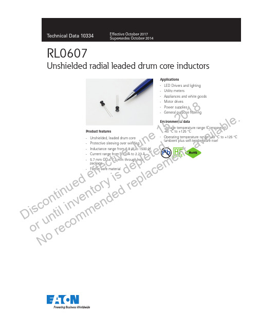
Product features•Unshielded, leaded drum core•Protective sleeving over winding•Inductance range from 6.8 μH to 1500 μH•Current range from 0.12 A to 2.23 A •5.7 mm OD x 7.3 mm through-holepackage•Ferrite core materialApplications• LED Drivers and lighting • Utility meters• Appliances and white goods • Motor drives • Power supplies•General purpose filteringEnvironmental data•Storage temperature range (Component):-40 °C to +125 °C•Operating temperature range: -40 °C to +125 °C(ambient plus self-temperature rise)RL0607Unshielded radial leaded drum core inductors7HALOGENHF FREEPb D i s c o n t i n u e d e f f e c t i v e J u n e 15, 2018o r u n t i l i n v e n t o r y i s d e p l e t e d . No r e c o m me n d e d r e p l a c e m e n t a v a i l a b le .2Technical Data 10334Effective October 2017RL0607Unshielded radial leaded drum core inductorsDimensions - mmProduct specificationsPart Number 4OCL¹ (μH) ±10%I rms 2 (A )I sat 3 (A )DCR (Ω) @ +20 °C max.SRF (MHz) typ.RL0607-6R8-R 6.8 ± 20%2.23 1.820.03826RL0607-100-R 10 1.82 1.510.05821RL0607-180-R 18 1.52 1.130.08316RL0607-330-R 33 1.080.8400.17111RL0607-470-R 470.9530.6900.2178RL0607-820-R 820.6860.5300.4266RL0607-151-R 1500.5200.3900.7304RL0607-221-R 2200.4230.320 1.103RL0607-471-R 4700.3060.220 2.002RL0607-821-R 8200.2190.170 4.132RL0607-102-R 10000.2050.150 4.761RL0607-152-R15000.1660.1207.2011.Open Circuit Inductance (OCL) Test Parameters: 10 kHz, 0.1 V rms , 0.0Adc,+25 °C2.I rms : DC current for an approximate temperature rise of 40 °C without core loss. Derating is necessary for AC currents. PCB layout, trace thickness and width, air-flow, and proximity of other heat generating components will affect the temperature rise. It is recommended that the temperature of the part not exceed +125 °C under worst case operating conditions verified in the end application.3. I sat : Peak current for approximately 5% rolloff at +25 °C4.Part Number Definition: RL0607-yyy-R-RL0607 = Product code and size-yyy= Inductance value in μH, R = decimal point,if no R is present then third character = number of zeros.-“-R” suffix = RoHS compliantSide view Recommended pad layout SchematicTop viewPart marking: 1xxxwly R1 = RL0607xxx = inductance in µH, R = decimal point; if there is no R, then third character = number of zeros wly = date code, R = revision level*Lead length is after the components are trimmed from the packaging tape roll.Do not route traces or vias underneath the inductor/el ectronicsf f e c t i v e J u n e 15, 2018o r d e p l e t e d . No r e c c e m e n t a v a i l a b l e ./el ectronics3RL0607Unshielded radial leaded drum core inductorsTechnical Data 10334Effective October 2017Packaging information - mmInductance characteristics020406080100120020406080100120140160180200% o f O C L% of I sat% of OCL vs % of I satD i s c o n t i n u e d e f f e c t i v o r u n t i l i n v e n t o r y i s d e p l e N o r e c o m me n d e d r e p l a c e m e le .Technical Data 10334Effective October 2017RL0607Unshielded radial leaded drum core inductorsReference EN 61760-1:2006 Profile Feature Standard SnPb Solder Lead (Pb) Free SolderPreheatTemperature min. (T smin ) 100°C100°C Temperature typ. (T styp ) 120°C 120°C Temperature max. (T smax ) 130°C130°CTime (T smin to T smax ) (t s )70 seconds 70 seconds∆preheat to max Temeperature150°C max. 150°C max. Peak temperature (T p )235°C - 260°C250°C - 260°CTime at peak temperature (t p )10 seconds max5 seconds max each wave 10 seconds max5 seconds max each wave Ramp-down rate~ 2 K/s min ~3.5 K/s typ ~5 K/s max ~ 2 K/s min ~3.5 K/s typ ~5 K/s max Time 25°C to 25°C4 minutes4 minutesManual solder350°C, 4-5 seconds. (by soldering iron), generally manual, hand soldering is not recommended.T e m p e r a t u r eTimeT T T T ∆Wave solder profileLife Support Policy: Eaton does not authorize the use of any of its products for use in life support devices or systems without the express written approval of an officer of the Company. Life support systems are devices which support or sustain life, and whose failure to perform, when properly used in accordance with instructions for use provided in the labeling, can be reasonably expected to result in significant injury to the user.Eaton reserves the right, without notice, to change design or construction of any products and to discontinue or limit distribution of any products. Eaton also reserves the right to change or update, without notice, any technical information contained in this bulletin.EatonElectronics Division 1000 Eaton Boulevard Cleveland, OH 44122United States/el ectronics © 2017 EatonAll Rights Reserved Printed in USAPublication No. 10334 BU-SB14688October 2017Eaton is a registered trademark.All other trademarks are property of their respective owners.D i s c o n t i n u e d e f f e c t i v e J u n e 158o r u n t i l i n v e n t o r y i s d e p l e t e d . No r e c o m me n d e d r e p l a c e m e n t a v a i l a b le .。
Envision H712a 用户手册说明书

Envision H712a User’s ManualTABLE OF CONTENTSFOR YOUR SAFETY --------------------------------------------------1 SAFETY PRECAUTIONS --------------------------------------2SPECIAL NOTES ON LCD MONITORS -------------------3 BEFORE YOU OPERATE THE MONITOR ---------------------3 FEATURES --------------------------------------------------------3PACKING LIST ---------------------------------------------------3INSTALLATION INSTRUCTIONS ---------------------------4CONTROLS AND CONNECTORS --------------------------5ADJUSTING THE VIEWING ANGLE-----------------------6 OPERATING INSTRUCTIONS -------------------------------------7 GENERAL INSTRUCTIONS----------------------------------7HOW TO ADJUST A SETTING ------------------------------9ADJUSTING THE PICTURE -----------------------------10-11PLUG AND PLAY ----------------------------------------------- 12 TECHNICAL SUPPORT(FAQ) ----------------------------------- 13 ERROR MESSAGE & POSSIBLE SOLUTION--------14 APPENDIX --------------------------------------------------------------15 SPECIFICATIONS -----------------------------------------15-16FACTORY PRESET TIMING TABLE ----------------------17CONNECTOR PIN ASSIGNMENT -------------------------18Before operating the monitor, please read this manual thoroughly. This manual should be retained for future reference.FCC Class B Radio Frequency Interference Statement WARNING: (FOR FCC CERTIFIED MODELS)NOTE: This equipment has been tested and found to comply with the limits for a Class B digital device, pursuant to Part 15 of the FCC Rules. These limits are designed to provide reasonable protection against harmful interference in a residential installation. This equipment generates, uses and can radiate radio frequency energy, and if not installed and used in accordance with the instructions, may cause harmful interference to radio communications. However, there is no guarantee that interference will not occur in a particular installation. If this equipment does cause harmful interference to radio or television reception, which can be determined by turning the equipment off and on, the user is encouraged to try to correct the interference by one or more of the following measures:1.Reorient or relocate the receiving antenna.2.Increase the separation between the equipment and receiver.3.Connect the equipment into an outlet on a circuit different from that towhich the receiver is connected.4.Consult the dealer or an experienced radio/TV technician for help. NOTICE:1.The changes or modifications not expressly approved by the partyresponsible for compliance could void the user's authority to operate the equipment.2.Shielded interface cables and AC power cord, if any, must be used inorder to comply with the emission limits.3.The manufacturer is not responsible for any radio or TV interferencecaused by unauthorized modification to this equipment. It is the responsibilities of the user to correct such interference.As an E NERGY S TAR®Partner our company has determined that this product meets the E NERGY S TAR®guidelines for energy efficiency. WARNING:To prevent fire or shock hazard, do not expose the monitor to rain or moisture. Dangerously high voltages are present inside the monitor. Do not open the cabinet. Refer servicing to qualified personnel only.PRECAUTIONS●Do not use the monitor near water, e.g. near a bathtub, washbowl,kitchen sink, laundry tub, swimming pool or in a wet basement.●Do not place the monitor on an unstable cart, stand, or table. If themonitor falls, it can injure a person and cause serious damage to the appliance. Use only a cart or stand recommended by the manufacturer or sold with the monitor. If you mount the monitor on a wall or shelf, use a mounting kit approved by the manufacturer and follow the kit instructions.●Slots and openings in the back and bottom of the cabinet are provided forventilation. To ensure reliable operation of the monitor and to protect it from overheating, be sure these openings are not blocked or covered. Do not place the monitor on a bed, sofa, rug, or similar surface. Do not place the monitor near or over a radiator or heat register. Do not place the monitor in a bookcase or cabinet unless proper ventilation is provided.●The monitor should be operated only from the type of power sourceindicated on the label. If you are not sure of the type of power supplied to your home, consult your dealer or local power company.●The monitor is equipped with a three-pronged grounded plug, a plug witha third (grounding) pin. This plug will fit only into a grounded power outletas a safety feature. If your outlet does not accommodate the three-wire plug, have an electrician install the correct outlet, or use an adapter to ground the appliance safely. Do not defeat the safety purpose of the grounded plug.●Unplug the unit during a lightening storm or when it will not be used forlong period of time. This will protect the monitor from damage due to power surges.●Do not overload power strips and extension cords. Overloading can resultin fire or electric shock.●Never push any object into the slot on the monitor cabinet. It could shortcircuit parts causing a fire or electric shock. Never spill liquids on the monitor.●Do not attempt to service the monitor by yourself; opening or removingcovers can expose you to dangerous voltages and other hazards. Please refer all servicing to qualified service personnel.●To ensure satisfactory operation, use the monitor only with UL listedcomputers which have appropriate configured receptacles marked between 100 - 240V AC, Min. 5A.●The wall socket shall be installed near the equipment and shall be easilyaccessible.SPECIAL NOTES ON LCD MONITORSThe following symptoms are normal with LCD monitor and do not indicate a problem.NOTES∙Due to the nature of the fluorescent light, the screen may flicker during initial use. Turn off the Power Switch and then turn it on again to make sure the flicker disappears.∙You may find slightly uneven brightness on the screen depending on the desktop pattern you use.∙The LCD screen has effective pixels of 99.99% or more. It may include blemishes of 0.01% or less such as a missing pixel or a pixel lit all of the time.∙Due to the nature of the LCD screen, an afterimage of the previous screen may remain after switching the image when the same image has been displayed for a long time. The monitor will slowly recover from this. BEFORE YOU OPERATE THE MONITORFEATURES∙43.2cm(17”) TFT Color LCD Monitor∙Crisp, Clear Display for Windows∙Recommened Resolutions: 1280X 1024 @60Hz∙EPA E NERGY S TAR®∙Ergonomic Design∙Space Saving, Compact Case DesignCHECKING THE CONTENTS OF THE PACKAGEThe product package should include the following items:1.LCD Monitor2.Owner's Manual3.Power Cord4.D-Sub Cable5.Audio CableINSTALLATION INSTRUCTIONSInstall RemoveFigure 1 Installing and Removing the Swivel BasePOWER CORDPower Source:1.Make sure that the power cord is the correct type required in your area.2.This LCD monitor has an External universal power supply that allowsoperation in either 100/120V AC or 220/240V AC voltage area (No user adjustment is required.)3.Connect the power cord into your LCD monitor’s power input socket, andthen plug the other end into a 3-pin AC power outlet. The power cord may be connected to either a wall power outlet or the power outlet socket on your PC, depending on the type of power cord supplied with your LCD monitor.NOTESA certified power supply cord has to be used with this equipment. The relevant national installation and/or equipment regulations shall be considered. A certified power supply cord not lighter than ordinary polyvinyl chloride flexible cord according to IEC 60227 (designation H05VV-F 3G 0.75mm2 or H05VVH2-F2 3G 0.75mm2) shall be used. Alternative a flexible cord be of synthetic rubber according to IEC 60245 (designation H05RR-F 3G 0.75mm2) shall be used.CONTROLS AND CONNECTORSVIDEO CABLEConnecting the D-Sub Cable: Connect one end of the 15-pin D-Sub cable to the back of the monitor and connect the other end to the computer’s D-Sub port.Connecting the Power Cord:Connect the power cord into your LCD monitor’s power input socket, and then plug the other end into a 3-pin AC power outlet. The power cord may be connected to either a wall power outlet or the power outlet socket on your PC, depending on the type of power cord supplied with your LCD monitor.Caution: If the AC outlet is not grounded (with three holes), install the proper grounding adapter (not supplied).Connecting the Audio Cable:Plug audio cable between the computer multi-media (or sound) card's audio output and monitor's audio input.Figure 2 Connecting Cables1.AC Power Cord2.D-Sub Cable3.Audio CableADJUSTING THE VIEWING ANGLE∙For optimal viewing it is recommended to look at the full face of the monitor, then adjust the monitor’s angle to your own preference.∙Hold the stand so you do not topple the monitor when you change the monitor’s angle.∙You are able to adjust the monitor’s angle from -5︒ to 20︒.Figure 3NOTES∙Do not touch the LCD screen when you change the angle. It may cause damage or break the LCD screen.∙Careful attention is required not to catch your fingers or hands when you change the angle.OPERATING INSTRUCTIONSGENERAL INSTRUCTIONSPress the power button to turn the monitor on or off. The other control buttons are located on the front panel of the monitor (See Figure 4). By changing these settings, the picture can be adjusted to your personal preferences.∙The power cord should be connected.∙Connect the video cable from the monitor to the video card.∙Press the power button to turn on the monitor position. The power indicator will light up.Figure 4 External Control ButtonEXTERNAL CONTROLS1.Auto Adjust Key/Exit 4.>/ Volume2.</ Volume 5.MENU/ENTER3.Power Key/ LEDFRONT PANEL CONTROL∙Power Button / Power Indicator:Press this button to turn the monitor ON or OFF.Blue—Power On mode.Orange—Off mode.∙MENU / ENTER :Activate OSD menu when OSD is OFF or activate/de-activate adjustment function when OSD is ON or Exit OSD menu when in Volume Adjust OSD status.∙> /Volume:Activates the volume control when the OSD is OFF or navigate through adjustment icons when OSD is ON or adjust a function when function is activated.∙< /Volume:Activates the volume control when the OSD is OFF or navigate through adjustment icons when OSD is ON or adjust a function when function is activated.∙Auto Adjust button / Exit:1.When OSD menu is in active status, this button will act as EXIT-KEY(EXIT OSD menu).2.When OSD menu is in off status, press this button for 2 seconds toactivate the Auto Adjustment function.The Auto Adjustment function is used to set the HPos, VPos, Clock and Focus.OSD Lock Function:To lock the OSD, press and hold the MENU button while the monitor is off and then press power button to turn the monitor on. To un-lock the OSD - press and hold the MENU button while the monitor is off and then press power button to turn the monitor on. NOTES∙Do not install the monitor in a location near heat sources such as radiators or air ducts, or in a place subject to direct sunlight, or excessive dust or mechanical vibration or shock.∙Save the original shipping carton and packing materials, as they will come in handy if you ever have to ship your monitor.∙For maximum protection, repackage your monitor as it was originally packed at the factory.∙To maintain the cleanness of your LCD display, wipe it periodically with clean and soft cloth. The screen may be damaged by any liquid splash.∙To keep the monitor looking new, periodically clean it with a soft cloth.Stubborn stains may be removed with a cloth lightly dampened with a mild detergent solution. Never use strong solvents such as thinner, benzene, or abrasive cleaners, since these will damage the cabinet. As a safety precaution, always unplug the monitor before cleaning it.HOW TO ADJUST A SETTING1.Press the MENU-button to activate the OSD window.2.Press< or > to navigate through the functions. Once the desiredfunction is highlighted, press the MENU-button to activate it. If the function selected has a sub-menu, press < or > again to navigate through the sub-menu functions. Once the desired function is highlighted, press MENU-button to activate it.3.Press< or > to change the settings of the selected function.4.To exit and save, select the exit function. If you want to adjust any otherfunction, repeat steps 2-3.Figure 5 The OSD MessageADJUSTING THE PICTUREThe descriptions for function control LEDSMain Menu Item Main Menu IconSub Menu Item Sub Menu IconDescriptionContrast Contrast from Digital-register.LuminanceBrightnessBacklight AdjustmentFocus Adjust Picture Phase to reduce Horizontal-Line noiseImage SetupClockAdjust picture Clock to reduce Vertical-Line noise.H. Position Adjust the horizontal position of the picture.Image PositionV. PositionAdjust the verticalposition of the picture.Warm N/A Recall Warm Color Temperature from EEPROM.Cool N/A Recall Cool Color Temperature from EEPROM.sRGB N/A Recall sRGB Temperature from EEPROM.User / Red Red Gain from er / Green Green Gain Digital-register.Color Temp.User / BlueBlue Gain from Digital-register.Main Menu ItemMain Menu IconSub Menu Item Sub Menu Icon DescriptionYesN/AAuto Adjust the H/V Position, Focus and Clock of picture.Auto ConfigNoN/ADo not execute Auto Config, return to main menu.H. Position Adjust the horizontal position of the OSD.V. Position Adjust the verticalposition of the OSD.OSD SetupOSD TimeoutAdjust the OSD timeout.Language Language N/A Set OSD language InformationInformatio n N/A Show the resolution, H/V frequency and input port of current input timing.Yes N/A Clear each old status of Auto-configuration.Reset NoN/A Do not execute reset, return to main menu.ExitN/AN/AExit OSDPLUG AND PLAYPlug & Play DDC2B FeatureThis monitor is equipped with VESA DDC2B capabilities according to the VESA DDC STANDARD. It allows the monitor to inform the host system of its identity and, depending on the level of DDC used, communicate additional information about its display capabilities.The DDC2B is a bidirectional data channel based on the I²C protocol. The host can request EDID information over the DDC2B channel.THIS MONITOR WILL APPEAR TO BE NON-FUNCTIONAL IF THERE IS NO VIDEO INPUT SIGNAL. IN ORDER FOR THIS MONITOR TO OPERATE PROPERLY, THERE MUST BE A VIDEO INPUT SIGNAL.This monitor meets the Green monitor standards as set by the Video Electronics Standards Association (VESA) and/or the United States Environmental Protection Agency (EPA) and The Swedish Confederation Employees (NUTEK). This feature is designed to conserve electrical energy by reducing power consumption when there is no video-input signal present. When there is no video input signal this monitor, following a time-out period, will automatically switch to an OFF mode. This reduces the monitor's internal power supply consumption. After the video input signal is restored, full power is restored and the display is automatically redrawn. The appearance is similar to a "Screen Saver" feature except the display is completely off. The display is restored by pressing a key on the keyboard, or clicking the mouse.TECHNICAL SUPPORT (FAQ)Problem & Question Possible SolutionPower LED is not on*Check if the Power Switch is in the ON position*Power Cord should be connectedNo Plug & Play *Check if the PC system is Plug & Playcompatible*Check if the Video Card is Plug & Play compatible*Check if the D-15 plug pin of Video Cable is bentPicture is fuzzy *Adjust the Contrast and BrightnessControls.Picture bounces or a wave pattern is present in the picture *Move electrical devices that may cause electrical interference.The power LED is ON but there’s no video or no picture.*Computer Power Switch should be in the ON position.*Computer Video Card should be snugly seated in its slot.*Make sure monitor’s video cable is properly connected to the computer.*Inspect monitor’s video cable and make sure none of the pins are bent.*Make sure computer is operational by hitting the CAPS LOCK key on the keyboard while observing the CAPS LOCK LED. The LED should either turn ON or OFF after hitting the CAPS LOCK key.Missing one of the primary colors (RED, GREEN, or BLUE)*Inspect the monitor’s video cable and make sure that none of the pins are bent.Screen image is not centered or sized properly.*Adjust pixel frequency (CLOCK) and FOCUS or press hot-key (AUTO).Picture has color defects (white does not look white)*Adjust RGB color or select color temperature.Horizontal or vertical disturbances on the screen *Use win 95/98 shut-down mode Adjust CLOCK and FOCUS or perform hot- key(AUTO-key).CLOCK (pixel frequency) controls the number of pixels scanned by one horizontal sweep. If the frequency is not correct, the screen shows vertical stripes and the picture has not correct width.FOCUS adjusts the phase of the pixel clock signal. With a wrong phase adjustment the picture has horizontal disturbances in light picture.For FOCUS and CLOCK adjustment use “dot-pattern” or win 95/98 shut-down mode pattern.ERROR MESSAGE & POSSIBLE SOLUTIONCABLE NOT CONNECTED :1.Check that the signal-cable is properly connected , If the connector isloose, tighten the connector’s screws.2.Check the signal-cable’s connection pins for damage.MODE NOT SUPPORTED :Your computer has been set to unsuitable display mode ,set the computer to display mode given in the following table (See page17).APPENDIXSPECIFICATIONSDriving system TFT Color LCDLCD Panel Size43.2cm(17.0")Pixel pitch0.264mm( H ) × 0.264mm( V )Video R,G,B Analog InterfaceInput Separate Sync.H/V TTLH-Frequency30kHz – 80kHzV-Frequency55-75HzDisplay Colors16.2M ColorsDot Clock135MHzMax. Resolution1280 × 1024Plug & Play VESA DDC2B TMON Mode≤37WEPA E NERGY S TAR®OFF Mode≤1WInput Connector15-pin D-SubInput Video Signal Analog:0.7Vp-p(standard),75 OHM, PositiveMaximum Screen Size Horizontal : 337.92mmVertical :270.34mmPower Source100~240VAC,50~60HzEnvironmental Considerations Operating Temp: 5° to 35°C Storage Temp.: -20° to 60°C Operating Humidity:10% to 85%Dimension371(W)×380(H)×106.4(D)mm Weight (N. W.) 4.5kg Unit (net)Switch∙Auto Adjust Key∙< / Volume∙> / Volume∙Power Button∙MENUExternal Controls:Functions∙Contrast∙Brightness∙Focus∙Clock∙H. Position∙V. Position∙Auto Config∙Language∙Information∙OSD Setup∙(Warm)Color∙(Cool)Color∙ sRGB∙User Color temperature∙Reset∙ExitAudio Output Rated Power 1.5 W rms(Per channel) Regulatory Compliance FCC,CE,cULusPreset Display ModesSTANDARD RESOLUTION HORIZONTALFREQUENCYVERTICALFREQUENCYDos-mode 720 x 400 31.47kHz70.0Hz640 × 48031.47kHz60.0Hz VGA640 × 48037.50kHz75.0Hz800 × 60037.879kHz60.0Hz SVGA800 × 60046.875kHz75.0Hz1024 × 76848.363kHz60.0Hz1024 × 76856.476kHz70.0Hz XGA1024 × 76860.021kHz75.0Hz1280 × 102464.000kHz60.0Hz SXGA1280 × 102480.000kHz75.0HzCONNECTOR PIN ASSIGNMENT15 - Pin Color Display Signal CablePIN NO.DESCRIPTION PIN NO.DESCRIPTION1.Red 9.+5V2.Green10.Detect Cable3.Blue11.Ground4.Ground12.DDC-Serial Data5.Ground13.H-Sync6.R-Ground14.V-Sync7.G-Ground15.DDC-Serial Clock8.B-Ground。
RI-07中文资料
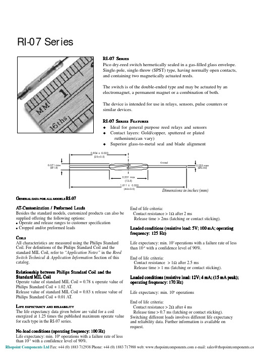
RI-07 SeriesRI-07 S ERIESPico dry-reed switch hermetically sealed in a gas-filled glass envelope.Single-pole, single-throw (SPST) type, having normally open contacts,and containing two magnetically actuated reeds.The switch is of the double-ended type and may be actuated by an electromagnet, a permanent magnet or a combination of both.The device is intended for use in relays, sensors, pulse counters or similar devices.RI-07 S ERIES F EATURESu Ideal for general purpose reed relays and sensors u Contact layers: Gold/copper, sputtered or platedruthenium (can vary)u Superior glass-to-metal seal and blade alignmentG ENERAL D A T A FOR ALL MODELS RI-07A T -Customization / Pr -Customization / Pref ef eformed Leadsormed Leads Besides the standard models, customized products can also be supplied offering the following options:! Operate and release ranges to customer specification ! Cropped and/or preformed leadsC OILSAll characteristics are measured using the Philips Standard Coil. For definitions of the Philips Standard Coil and the standard MIL Coil, refer to “Application Notes” in the Reed Switch Technical & Application Information Section of this catalog.Relationship betw Relationship between Philips Standar een Philips Standar een Philips Standard Coil and the d Coil and the Standar Standard MIL Coild MIL Coil Operate value of standard MIL Coil = 0.78 x operate value of Philips Standard Coil + 1.02 AT.Release value of standard MIL Coil = 0.83 x release value of Philips Standard Coil + 0.01 AT.L IFE EXPECT EXPECTANCYANCY AND RELIABILITY The life expectancy data given below are valid for a coilenergized at 1.25 times the published maximum operate value for each type in the RI-07 series.No-load conditions (operating frequency: 100 Hz)Life expectancy: min. 108 operations with a failure rate of less than 10-9 with a confidence level of 90%.End of life criteria:Contact resistance > 1Ω after 2 msRelease time > 2ms (latching or contact sticking).Loaded conditions (resistive load: 5V; 100 mA; operating fr frequency:equency:equency: 125 Hz)125 Hz)Life expectancy: min. 107 operations with a failure rate of less than 10-8 with a confidence level of 90%.End of life criteria:Contact resistance > 1Ω after 2.5 msRelease time > 1 ms (latching or contact sticking).Loaded conditions (resistive load: 12V; 4 mA; (15 mA peak);operating frequency: 170 Hz)Life expectancy: min. 106 operationsEnd of life criteria:Contact resistance > 2Ω after 4 msRelease time > 0.7 ms (latching or contact sticking).Switching different loads involves different life expectancy and reliability data. Further information is available on request.Dimensions in inches (mm)RI-07 SeriesM ECHANICAL D ATAContact arrangement is normally open; lead finish is tinned;net mass is approximately 0.10 g; and can be mounted in any position.S HOCKThe switches are tested in accordance with “IEC 68-2-27”, test Ea (peak acceleration 150 G, half sinewave; duration 11 ms).Such a shock will not cause an open switch (no magnetic field present) to close, nor a switch kept closed by an 80 AT coil to open.V IBRA IBRATIONTION The switches are tested in accordance with “IEC 68-2-6”, test Fc (acceleration 10 G; below cross-over frequency 57 to 62Hz; amplitude 0.75 mm; frequency range 10 to 2000 Hz,duration 90 minutes). Such a vibration will not cause an open switch (no magnetic field present) to close, nor a switch kept closed by an 80 A T coil to open.M ECHANICAL S TRENGTHThe robustness of the terminations is tested in accordance with “IEC 68-2-21”, test Ua 1 (load 10 N).O PERA TING AND S T ORA ORAGEGE T EMPERA TURE Operating ambient temperature; min: -55°C; max: +125°C.Storage temperature; min: -55°C; max: +125°C.Note:Note: Temperature excursions up to 150°C may be permissible.For more information contact your nearest Coto Technology sales office.S OLDERINGThe switch can withstand soldering heat in accordance with “IEC 68-2-20”, test Tb, method 1B: solder bath at 350 ±10° C for 3.5 ±0.5 s.Solderability is tested in accordance with “IEC 68-2-20” test Ta, method 3: solder globule temperature 235°C; ageing 1b:4 hours steam.W ELDINGThe leads can be weldedM OUNTINGThe leads should not be bent closer than 1 mm to the glass-to-metal seals. Stress on the seals should be avoided. Care must be taken to prevent stray magnetic fields from influencing the operating and measuring conditions.Model Number RI-07AAARI-07AARI-07AParametersTest Conditions Units。
BD7967EFS资料
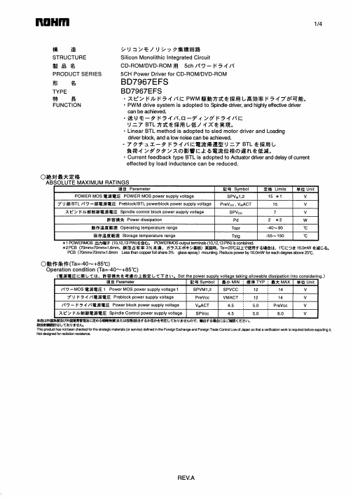
The products listed in this document are designed to be used with ordinary electronic equipment or devices (such as audio visual equipment, office-automation equipment, communications devices, electrical appliances and electronic toys). Should you intend to use these products with equipment or devices which require an extremely high level of reliability and the malfunction of with would directly endanger human life (such as medical instruments, transportation equipment, aerospace machinery, nuclear-reactor controllers, fuel controllers and other safety devices), please be sure to consult with our sales representative in advance. About Export Control Order in Japan Products described herein are the objects of controlled goods in Annex 1 (Item 16) of Export Trade Control Order in Japan. In case of export from Japan, please confirm if it applies to "objective" criteria or an "informed" (by MITI clause) on the basis of "catch all controls for Non-Proliferation of Weapons of Mass Destruction.
数控刀柄知识
数控刀具中刀柄的应用知识加工中心的主轴锥孔通常分为两大类,即锥度为7:24的通用系统和1:10的HSK真空系统。
一、7:24锥度的通用刀柄7:24锥度的通用刀柄锥度为7:24的通用刀柄通常有五种标准和规格,即NT (传统型)、DIN 69871(德国标准)、IS0 7388/1 (国际标准)、MAS BT(日本标准)以及ANSI/ASME(美国标准)。
NT型刀柄德国标准为DIN 2080,是在传统型机床上通过拉杆将刀柄拉紧,国内也称为ST;其它四种刀柄均是在加工中心上通过刀柄尾部的拉钉将刀柄拉紧。
目前国内使用最多的是DIN 69871型(即JT)和MAS BT 型两种刀柄。
DIN 69871型的刀柄可以安装在DIN 69871型和ANSI/ASME主轴锥孔的机床上, IS0 7388/1型的刀柄可以安装在DIN 69871型、IS0 7388/1 和ANSI/ASME主轴锥孔的机床上,所以就通用性而言,IS0 7388/1型的刀柄是最好的。
(1)DIN 2080型(简称 NT或ST)DIN 2080是德国标准,即国际标准ISO 2583 ,是我们通常所说NT型刀柄,不能用机床的机械手装刀而用手动装刀。
(2) DIN 69871 型(简称JT、 DIN、DAT或DV)DIN 69871 型分两种,即DIN 69871 A/AD型和 DIN 69871 B型,前者是中心内冷,后者是法兰盘内冷,其它尺寸相同。
(3) ISO 7388/1 型(简称 IV或IT)其刀柄安装尺寸与DIN 69871 型没有区别,但由于ISO 7388/1 型刀柄的D4值小于DIN 69871 型刀柄的D4值,所以将ISO 7388/1型刀柄安装在DIN 69871型锥孔的机床上是没有问题的,但将DIN 69871 型刀柄安装在ISO 7388/1型机床上则有可能会发生干涉。
(4) MAS BT 型(简称 BT)BT型是日本标准,安装尺寸与 DIN 69871、IS0 7388/1 及ANSI 完全不同,不能换用。
OSRAM OSLON WL-T7DS 蓝色LED光源说明书
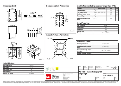
Dimensions: [mm]15detail AScale - 2:1157119B12701Schematic:157119B12701157119B12701157119B12701157119B12701157119B12701157119B12701T e m p e r a t u r eT T T 157119B12701Cautions and Warnings:The following conditions apply to all goods within the product series of Optoelectronic Components of Würth Elektronik eiSos GmbH & Co. KG:General:•This optoelectronic component is designed and manufactured for use in general electronic equipment.•Würth Elektronik must be asked for written approval (following the PPAP procedure) before incorporating the components into any equipment in fields such as military, aerospace, aviation, nuclear control, submarine, transportation (automotive control, train control, ship control), transportation signal, disaster prevention, medical, public information network, etc. where higher safety and reliability are especially required and/or if there is the possibility of direct damage or human injury.•Optoelectronic components that will be used in safety-critical or high-reliability applications, should be pre-evaluated by the customer. •The optoelectronic component is designed and manufactured to be used within the datasheet specified values. If the usage and operation conditions specified in the datasheet are not met, the wire insulation may be damaged or dissolved.•Do not drop or impact the components, the component may be damaged•Würth Elektronik products are qualified according to international standards, which are listed in each product reliability report. Würth Elektronik does not warrant any customer qualified product characteristics beyond Würth Elektroniks’ specifications, for its validity and sustainability over time.•The responsibility for the applicability of the customer specific products and use in a particular customer design is always within the authority of the customer. All technical specifications for standard products also apply to customer specific products.Product specific:Soldering:•The solder profile must comply with the technical product specifications. All other profiles will void the warranty.•All other soldering methods are at the customers’ own risk.Cleaning and Washing:•Washing agents used during the production to clean the customer application might damage or change the characteristics of the optoelectronic component body, marking or plating. Washing agents may have a negative effect on the long-term functionality of the product.•Using a brush during the cleaning process may break the optoelectronic component body. Therefore, we do not recommend using a brush during the PCB cleaning process.Potting:•If the product is potted in the customer application, the potting material might shrink or expand during and after hardening. Shrinking could lead to an incomplete seal, allowing contaminants into the optoelectronic component body, pins or termination. Expansion could damage the components. We recommend a manual inspection after potting to avoid these effects.Storage Conditions:• A storage of Würth Elektronik products for longer than 12 months is not recommended. Within other effects, the terminals may suffer degradation, resulting in bad solderability. Therefore, all products shall be used within the period of 12 months based on the day of shipment.•Do not expose the optoelectronic component to direct sunlight.•The storage conditions in the original packaging are defined according to DIN EN 61760-2.•For a moisture sensitive component, the storage condition in the original packaging is defined according to IPC/JEDEC-J-STD-033. It is also recommended to return the optoelectronic component to the original moisture proof bag and reseal the moisture proof bag again. •The storage conditions stated in the original packaging apply to the storage time and not to the transportation time of the components. Packaging:•The packaging specifications apply only to purchase orders comprising whole packaging units. If the ordered quantity exceeds or is lower than the specified packaging unit, packaging in accordance with the packaging specifications cannot be ensured. Handling:•Violation of the technical product specifications such as exceeding the nominal rated current, will void the warranty.•The product design may influence the automatic optical inspection.•Certain optoelectronic component surfaces consist of soft material. Pressure on the top surface has to be handled carefully to prevent negative influence to the function and reliability of the optoelectronic components.•ESD prevention methods need to be applied for manual handling and processing by machinery.•Resistors for protection are obligatory.•Luminaires in operation may harm human vision or skin on a photo-biological level. Therefore direct light impact shall be avoided. All products are additionally certified as risk groups 0 to 2 according to DIN EN 62471:2008.•In addition to optoelectronic components testing, products incorporating these devices have to comply with the safety precautions given in IEC 60825-1, IEC 62471 and IEC 62778•Please be aware that Products provided in bulk packaging may get bent and might lead to derivations from the mechanical manufacturing tolerances mentioned in our datasheet, which is not considered to be a material defect.Technical specification:•The typical and/or calculated values and graphics of technical parameters can only reflect statistical figures. The actual parameters of each single product, may differ from the typical and/or calculated values or the typical characteristic line.•On each reel, only one bin is sorted and taped. The bin is defined on intensity, chromaticity coordinate or wavelength and forwardWürth Elektronik eiSos GmbH & Co. KGEMC & Inductive SolutionsMax-Eyth-Str. 174638 WaldenburgGermanyCHECKED REVISION DATE (YYYY-MM-DD)GENERAL TOLERANCE PROJECTIONMETHODPLD001.0012023-05-27DIN ISO 2768-1mDESCRIPTIONWL-T7DS 7 Segments Display THTSingle Digit ORDER CODE157119B12701SIZE/TYPE BUSINESS UNIT STATUS PAGEvoltage.•In order to ensure highest availability, the reel binning of standard deliveries can vary. A single bin cannot be ordered. Please contact us in advance, if you need a particular bin sorting before placing your order.•Test conditions are measured at the typical current with pulse duration < 30ms. •Wavelength tolerance under measurement conditions ± 2nm. •Optical intensity tolerance under measurement conditions ±15%. •Forward voltage tolerance under measurement conditions ± 0.2V.These cautions and warnings comply with the state of the scientific and technical knowledge and are believed to be accurate and reliable.However, no responsibility is assumed for inaccuracies or incompleteness.Würth Elektronik eiSos GmbH & Co. KG EMC & Inductive Solutions Max-Eyth-Str. 174638 Waldenburg GermanyCHECKED REVISION DATE (YYYY-MM-DD)GENERAL TOLERANCEPROJECTION METHODPLD001.0012023-05-27DIN ISO 2768-1mDESCRIPTIONWL-T7DS 7 Segments Display THT Single DigitORDER CODE157119B12701SIZE/TYPEBUSINESS UNITSTATUSPAGEImportant NotesThe following conditions apply to all goods within the product range of Würth Elektronik eiSos GmbH & Co. KG:1. General Customer ResponsibilitySome goods within the product range of Würth Elektronik eiSos GmbH & Co. KG contain statements regarding general suitability for certain application areas. These statements about suitability are based on our knowledge and experience of typical requirements concerning the areas, serve as general guidance and cannot be estimated as binding statements about the suitability for a customer application. The responsibility for the applicability and use in a particular customer design is always solely within the authority of the customer. Due to this fact it is up to the customer to evaluate, where appropriate to investigate and decide whether the device with the specific product characteristics described in the product specification is valid and suitable for the respective customer application or not.2. Customer Responsibility related to Specific, in particular Safety-Relevant ApplicationsIt has to be clearly pointed out that the possibility of a malfunction of electronic components or failure before the end of the usual lifetime cannot be completely eliminated in the current state of the art, even if the products are operated within the range of the specifications.In certain customer applications requiring a very high level of safety and especially in customer applications in which the malfunction or failure of an electronic component could endanger human life or health it must be ensured by most advanced technological aid of suitable design of the customer application that no injury or damage is caused to third parties in the event of malfunction or failure of an electronic component. Therefore, customer is cautioned to verify that data sheets are current before placing orders. The current data sheets can be downloaded at .3. Best Care and AttentionAny product-specific notes, cautions and warnings must be strictly observed. Any disregard will result in the loss of warranty.4. Customer Support for Product SpecificationsSome products within the product range may contain substances which are subject to restrictions in certain jurisdictions in order to serve specific technical requirements. Necessary information is available on request. In this case the field sales engineer or the internal sales person in charge should be contacted who will be happy to support in this matter.5. Product R&DDue to constant product improvement product specifications may change from time to time. As a standard reporting procedure of the Product Change Notification (PCN) according to the JEDEC-Standard inform about minor and major changes. In case of further queries regarding the PCN, the field sales engineer or the internal sales person in charge should be contacted. The basic responsibility of the customer as per Section 1 and 2 remains unaffected.6. Product Life CycleDue to technical progress and economical evaluation we also reserve the right to discontinue production and delivery of products. As a standard reporting procedure of the Product Termination Notification (PTN) according to the JEDEC-Standard we will inform at an early stage about inevitable product discontinuance. According to this we cannot guarantee that all products within our product range will always be available. Therefore it needs to be verified with the field sales engineer or the internal sales person in charge about the current product availability expectancy before or when the product for application design-in disposal is considered. The approach named above does not apply in the case of individual agreements deviating from the foregoing for customer-specific products.7. Property RightsAll the rights for contractual products produced by Würth Elektronik eiSos GmbH & Co. KG on the basis of ideas, development contracts as well as models or templates that are subject to copyright, patent or commercial protection supplied to the customer will remain with Würth Elektronik eiSos GmbH & Co. KG. Würth Elektronik eiSos GmbH & Co. KG does not warrant or represent that any license, either expressed or implied, is granted under any patent right, copyright, mask work right, or other intellectual property right relating to any combination, application, or process in which Würth Elektronik eiSos GmbH & Co. KG components or services are used.8. General Terms and ConditionsUnless otherwise agreed in individual contracts, all orders are subject to the current version of the “General Terms and Conditions of Würth Elektronik eiSos Group”, last version available at .Würth Elektronik eiSos GmbH & Co. KGEMC & Inductive SolutionsMax-Eyth-Str. 174638 WaldenburgGermanyTel. +49 (0) 79 42 945 - 0*******************CHECKED REVISION DATE (YYYY-MM-DD)GENERAL TOLERANCE PROJECTIONMETHODPLD001.0012023-05-27DIN ISO 2768-1mDESCRIPTIONWL-T7DS 7 Segments Display THTSingle Digit ORDER CODE157119B12701SIZE/TYPE BUSINESS UNIT STATUS PAGE0.39"eiPal PCN11/11This electronic component has been designed and developed for usage in general electronic equipment only. This product is not authorized for use in equipment where a higher safety standard and reliability standard is especially required or where a failure of the product is reasonably expected to cause severe personal injury or death, unless the parties have executed an agreement specifically governing such use. Moreover Würth Elektronik eiSos GmbH & Co KG products are neither designed nor intended for use in areas such as military, aerospace, aviation, nuclear control, submarine, transportation, transportation signal, disaster prevention, medical, public information network etc.. Würth Elektronik eiSos GmbH & Co KG must be informed about the intent of such usage before the design-in stage. In addition, sufficient reliability evaluation checks for safety must be performed on every electronic component which is used in electrical circuits that require high safety and reliability functions or performance.。
止退型螺纹紧固件使用说明

止退型螺纹紧固件说明书产品简介止退型螺纹紧固件是针对振动频率高、冲击载荷大、需要可靠连接的部位,不容易检查的关键连接部位设计的特种螺纹紧固件;是具有良好的紧固可靠性和实用性的专利产品。
采用棘轮锁闭方式形位定位,紧固后不松动。
完整通过国家军用标准(GJB715.3)检测,无松动。
(检测单位:国防科工委航天标准紧固件研究与检测中心)在实际使用过程中,从未出现松动。
自主知识产权,已获得中国、欧盟、日本专利权。
功能及特点紧固即锁闭定位,在恶劣工况中不松动;紧固连接可靠,减少部件损坏,保证设备质量,避免连接松动引起的故障、事故;多种系列产品形式,与通用紧固件的紧固方式相同,适用于各种通孔和螺纹盲孔连接;用专用工具拆卸可重复使用;用通用工具拆卸,更换垫圈后,也可以重复使用。
在国标范围内,利用设计冗余进行局部改动,主要技术指标与国家标准兼容。
产品六角头螺栓参照(GB/T5782-2000)六角头螺栓全螺纹参照(GB/T5783-2000)标记示例:螺纹规格d=M12、公称长度l=80mm、性能等级为8.8级、不经表面处理的六角头螺栓:螺栓SKS5780 M12×80螺纹规格d M10 M12M14 M16 M18 M20 M22 M24 M27 M30 M36 M42 M48 M56 M64s (公称) 16 18 21 24 27 30 34 36 41 46 55 65 75 85 95 k (公称) 6.4 7.5 8.8 10 11.5 12.5 14 15 17 18.7 22.5 26 30 35 40 r min 0.4 0.6 0.6 0.6 0.6 0.8 0.8 0.8 1 1 1 1.2 1.6 2 2e min 17.59 19.8522.78 26.17 29.56 32.95 37.29 39.55 45.2 50.85 60.79 71.3 82.6 93.56 104.86dw min 14.47 16.4719.15 22 24.85 27.7 31.35 33.25 38 42.75 51.11 59.95 69.45 78.86 88.16b (参考) l≤125125<l≤200l>200263245303649344053384457424861465265505669546073606679667285~8497~96109~108121~~137~~153 a 4.5 5.25 6 7.5 9 10.5~ 12 13.5~ 15 16.5 18全螺纹长度l 20~10025~12030~14035~15035~18040~15045~20050~15055~20060~20070~20080~200100~200110~200120~200100mm长的质量≈/kg 0.0660.0940.132 0.178 0.229 0.289 0.366 0.431 0.569 0.722 1.099 1.611 2.254 3.224 4.427l系列(公称)20,25,30,35,40,45,50,55,60,65,70,80,90,100,110,120,130,140,150,160,注:1、A级用于d≤24mm和l≤10d或l≤150mm的螺栓,B级用于d>24mm和l>10d或>150mm的螺栓2、表面处理:氧化处理不标;如需其它方式处理,标明处理方式类型。
NS6L083AT-H1中文资料
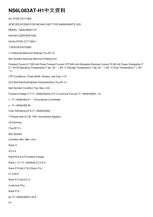
NS6L083AT-H1中⽂资料No. STSE-CC7138ASPECIFICATIONS FOR NICHIA CHIP TYPE WARM WHITE LEDMODEL : NS6L083AT-H1NICHIA CORPORATIONNichia STSE-CC7138A-11.SPECIFICATIONS(1) Absolute Maximum Ratings (Ta=25°C)Item Symbol Absolute Maximum Rating UnitForward Current I F 350 mA Pulse Forward Current I FP 600 mA Allowable Reverse Current I R 85 mA Power Dissipation P D 1.54 W Operating Temperature T opr -30 ~ + 85 °C Storage Temperature T stg -40 ~ +100 °C Dice Temperature T j 120°CI FP Conditions : Pulse Width 10msec. and Duty 1/10(2) Initial Electrical/Optical Characteristics (Ta=25°C)Item Symbol Condition Typ. Max. UnitForward Voltage V F I F =300[mA](3.8) 4.4 V Luminous Flux φv I F =300[mA](52) - lmx - I F =300[mA]0.41 - - Chromaticity Coordinatey - I F =300[mA]0.39 - -Color Rendering R a I F =300[mA](92) - -Please refer to CIE 1931 chromaticity diagram.(3) Ranking(Ta=25°C)Item SymbolCondition Min. Max. UnitRank H4.0 4.4Rank M 3.6 4.0 Forward VoltageRank L V F I F =300[mA] 3.2 3.6 VRank P15 60.5 72.0 Rank P1451.0 60.5Rank P13 42.8 51.0Luminous FluxRank P12φv I F =300[mA]36.0 42.8lmColor Rendering- R a I F =300[mA]85 - -Forward Voltage Measurement allowance is ± 3%.Luminous Flux Measurement allowance is ± 10%. Color Rendering Measurement allowance is ± 5.Color Ranks (I F =300mA,Ta=25°C)Rank d1 x 0.3575 0.3610 0.3780 0.39880.38970.3720y 0.3612 0.3850 0.3970 0.41160.38230.3714Rank d2 x 0.3545 0.3575 0.3720 0.38970.38220.3667y 0.3408 0.3612 0.3714 0.38230.35800.3484Rank e1 x 0.3897 0.3988 0.4162 0.43900.42550.4053y 0.3823 0.4116 0.4200 0.43100.40000.3907<= <=Nichia STSE-CC7138A-1Rank e2 x 0.3822 0.3897 0.4053 0.42550.41290.3954y 0.3580 0.3823 0.3907 0.40000.37250.3642Rank f3 Rank f4 x 0.4255 0.4390 0.4680 0.4519x 0.45190.46800.4970 0.4770y 0.4000 0.4310 0.4385 0.4086y 0.40860.43850.4466 0.4137Rank f5Rank f6x 0.4129 0.4255 0.4519 0.4355x 0.43550.45190.4770 0.4588y 0.3725 0.4000 0.4086 0.3785y 0.37850.40860.4137 0.3838Color Coordinates Measurement allowance is ± 0.01.Basically, a shipment shall consist of the LEDs of a combination of the above ranks. The percentage of each rank in the shipment shall be determined by Nichia.2.INITIAL OPTICAL/ELECTRICAL CHARACTERISTICSPlease refer to figure’s page.3.OUTLINE DIMENSIONS AND MATERIALSPlease refer to figure’s page.Material as follows ; Package : Heat-ResistantPolymer Encapsulating Resin: Silicone Resin (with Phosphor) Electrodes : Ag Plating Copper Alloy4.PACKAGING· The LEDs are packed in cardboard boxes after taping. Please refer to figure’s page.The label on the minimum packing unit shows ; Part Number, Lot Number, Ranking, Quantity· In order to protect the LEDs from mechanical shock, we pack them in cardboard boxes for transportation. · The LEDs may be damaged if the boxes are dropped or receive a strong impact against them, so precautions must be taken to prevent any damage.· The boxes are not water resistant and therefore must be kept away from water and moisture.· When the LEDs are transported, we recommend that you use the same packing method as Nichia.5.LOT NUMBERThe first six digits number shows lot number .The lot number is composed of the following characters; { ¯¯¯¯ - U z{ - Year ( 6 for 2006, 7 for 2007 ) - Month ( 1 for Jan., 9 for Sep., A for Oct., B for Nov. ) ¯¯¯¯ - Nichia's Product Number U -Ranking by Color Coordinates - Ranking by Luminous Flux z - Ranking by Forward VoltageShaded ranks are available .NichiaSTSE-CC7138A6.RELIABILITY(1) TEST ITEMS AND RESULTSTest Item StandardTest Method Test Conditions NoteNumber ofDamagedResistance to Soldering Heat (Reflow Soldering) JEITA ED-4701300 301Tsld=260°C, 10sec.(Pre treatment 30°C,70%,168hrs.)2 times 0/22Solderability (Reflow Soldering) JEITA ED-4701300 303Tsld=215 ± 5°C, 3sec.(Lead Solder)1 timeover 95%0/22Temperature Cycle JEITA ED-4701100 105-40°C ~ 25°C ~ 100°C ~ 25°C30min.5min.30min.5min.100 cycles 0/50Moisture Resistance Cyclic JEITA ED-4701200 20325°C ~ 65°C ~ -10°C90%RH 24hrs./1cycle10 cycles 0/22High Temperature Storage JEITA ED-4701200 201Ta=100°C 1000 hrs. 0/22Temperature Humidity Storage JEITA ED-4701100 103Ta=60°C, RH=90% 1000 hrs. 0/22Low Temperature Storage JEITA ED-4701200 202Ta=-40°C 1000 hrs. 0/22 Steady State Operating Life Ta=25°C,I F=350mATested with Nichia standard circuit board.1000 hrs. 0/22Steady State Operating Life of High TemperatureTa=85°C,I F=160mATested with Nichia standard circuit board.1000 hrs. 0/22Steady State Operating Life of High Humidity Heat60°C, RH=90%, I F=250mATested with Nichia standard circuit board.500 hrs. 0/22Steady State Operating Life of Low TemperatureTa=-30°C,I F=300mATested with Nichia standard circuit board.1000 hrs. 0/22Vibration JEITA ED-4701400 403100 ~ 2000 ~ 100Hz Sweep 4min.200m/s23directions, 4cycles48min. 0/22Substrate Bending JEITA ED-4702 3mm, 5 ± 1 sec. 1 time 0/22 Adhesion Strength JEITA ED-4702 5N, 10 ± 1 sec. 1 time 0/22Electrostatic Discharges JEITA ED-4701300 304 R=1.5k?, C=100pFTest Voltage=2kV3 timesNegative/Positive0/22Thermal resistance of LED with Nichia standard circuit board : Rja ≒ 65°C/WNichia standard circuit board : FR4, t=1.6mm, Copper foil, t=0.07mm(2) CRITERIA FOR JUDGING DAMAGECriteria for JudgementItem Symbol Test Conditions Min. Max. Forward Voltage V F I F=300mA -InitialLevel1.1 Luminous Flux φv I F=300mA InitialLevel0.7-The test is performed after the board is cooled down to the room temperature.Nichia STSE-CC7138A7.CAUTIONSThe LEDs are devices which are materialized by combining Blue LEDs and special phosphors. Consequently, the color of the LEDs is changed a little by an operating current.Care should be taken after due consideration when using LEDs.(1) Moisture Proof Package· When moisture is absorbed into the SMT package it may vaporize and expand during soldering.There is a possibility that this can cause exfoliation of the contacts and damage the opticalcharacteristics of the LEDs. For this reason, the moisture proof package is used to keep moisture to a minimum in the package.· The moisture proof package is made of an aluminum moisture proof bag. A package ofa moisture absorbent material (silica gel) is inserted into the aluminium moisture proof bag.The silica gel changes its color from blue to pink as it absorbs moisture.(2) Storage· Storage ConditionsBefore opening the package :The LEDs should be kept at 30°C or less and 90%RH or less. The LEDs should be used withina year. When storing the LEDs, moisture proof packaging with absorbent material (silica gel)is recommended.After opening the package :The LEDs should be kept at 30°C or less and 70%RH or less. The LEDs should be soldered within 168 hours (7days) after opening the package. If unused LEDs remain, they should bestored in the moisture proof packages, such as sealed containers with packages of moisture absorbent material (silica gel). It is also recommended to return the LEDs to the originalmoisture proof bag and to reseal the moisture proof bag again.· If the moisture absorbent material (silica gel) has faded away or the LEDs have exceeded the storage time, baking treatment should be performed using the following condition.Baking treatment : more than 24 hours at 65 ± 5°C· Nichia LED electrodes, leadframes and Die Heat sink are silver plated copper alloy.The silver surface may be affected by environments which contain corrosive substances.Please avoid conditions which may cause the LED to corrode, tarnish or discolor. This corrosion or discoloration might lower solderability or might affect on optical characteristics. There is a possibility of accelerate corrosion if the LEDs are exposed to corrosive substances in high temperature.· Please avoid rapid transitions in ambient temperature, especially in high humidity environments wherecondensation can occur.(3) Recommended circuit· In designing a circuit, the current through each LED must not exceed its absolute maximum rating.It is recommended to use Circuit B which regulates the current flowing through each LED.In the meanwhile, when driving LEDs with a constant voltage in Circuit A, the current throughthe LEDs may vary due to the variation in forward voltage (V F) of the LEDs. In the worst case,some LED may be subjected to stresses in excess of the absolute maximum rating.(A)120sec.Max. Pre-heating 260°C Max.10sec. Max. 60sec.Max. Above 220°C 1 ~ 5°C / sec.1 ~ 5°C / sec. 180 ~ 200°C <1 : Lead Solder><2 : Lead-free Solder>Pre-heating240°C Max.10sec. Max. 60sec.Max. Above 200°C2.5 ~ 5°C / sec. 2.5 ~ 5°C / sec. 120 ~ 150°C 120sec.Max.Nichia STSE-CC7138A(4) Soldering Conditions· The LEDs can be soldered in place using the reflow soldering method. Nichia cannot make a guarantee on the LEDs after they have been assembled using the dip soldering method. · Recommended soldering conditionsReflow SolderingHand SolderingLead Solder Lead-free Solder Pre-heat Pre-heat time Peak temperature Soldering time Condition 120 ~ 150°C 120 sec. Max. 240°C Max. 10 sec. Max. refer to Temperature - profile 1. 180 ~ 200°C 120 sec. Max. 260°C Max. 10 sec. Max. refer to Temperature - profile 2.(N 2 reflow is recommended.)TemperatureSoldering time350°C Max. 3 sec. Max.(one time only) Although the recommended soldering conditions are specified in the above table, reflow or handsoldering at the lowest possible temperature is desirable for the LEDs.A rapid-rate process is not recommended for cooling the LEDs down from the peak temperature. [Temperature-profile (Surface of circuit board)] Use the conditions shown to the under figure.[Recommended soldering pad design] Use the following conditions shown in the figure.Thin line boxes :Solder resist openingThick line boxes :Land patternMake sure the die heat sink is electrically connected to the cathode(K).· Occasionally there is a brightness decrease caused by the influence of heat or ambient atmosphere during air reflow. It is recommended that the User use the nitrogen reflow method.· The encapsulated material of the LEDs is silicone. Therefore the LEDs have a soft surface on the top of package. The pressure to the top surface will be influence to the reliability of the LEDs. Precautions should be taken to avoid the strong pressure on the encapsulated part. So when using the chip mounter, the picking up nozzle that does not affect the silicone resin should be used.· Repairing should not be done after the LEDs have been soldered. When repairing is unavoidable, a hot plate should be used. It should be confirmed beforehand whether the characteristics of the LEDs will or will not be damaged by repairing.· Reflow soldering should not be done more than two times.· Die Heat sink is to be soldered. If not, please use the heat conductive adhesive. · When soldering, do not put stress on the LEDs during heating. · After soldering, do not warp the circuit board.(Unit : mm)Nichia STSE-CC7138A(5) Cleaning· It is recommended that isopropyl alcohol be used as a solvent for cleaning the LEDs. When using other solvents, it should be confirmed beforehand whether the solvents will dissolve the package and the resin or not. Freon solvents should not be used to clean the LEDs because of worldwide regulations. · Do not clean the LEDs by the ultrasonic. When it is absolutely necessary, the influence of ultrasonic cleaning on the LEDs depends on factors such as ultrasonic power and the assembled condition.Before cleaning, a pre-test should be done to confirm whether any damage to the LEDs will occur.(6) Static Electricity· Static electricity or surge voltage damages the LEDs.It is recommended that a wrist band or an anti-electrostatic glove be used when handling the LEDs.· All devices, equipment and machinery must be properly grounded. It is recommended that precautions be taken against surge voltage to the equipment that mounts the LEDs.· When inspecting the final products in which LEDs were assembled, it is recommended to checkwhether the assembled LEDs are damaged by static electricity or not. It is easy to findstatic-damaged LEDs by a light-on test or a VF test at a lower current (below 6mA is recommended). · Damaged LEDs will show some unusual characteristics such as the forward voltage becomes lower, or the LEDs do not light at the low current. Criteria : (V F> 2.0V at I F=3mA)(7) Heat Generation· Thermal design of the end product is of paramount importance. Please consider the heat generation of the LED when making the system design. The coefficient of temperature increase per inputelectric power is affected by the thermal resistance of the circuit board and density of LED placement on the board, as well as other components. It is necessary to avoid intense heat generation and operate within the maximum ratings given in this specification.· Please determine the operating current with consideration of the ambient temperature local to the LED and refer to the plot of Ambient temperature vs. Allowable Forward Current on CHARACTERISTICS in this specifications. Please also take measures to remove heat from the area near the LED (heat sink) to improve the operational characteristics of the LED.· The equation 1 indicates correlation between Tj and Ta, and the equation 2 indicates correlationbetween Tj and Ts.Tj=Ta + Rja W 1Tj=Ts + Rjs W 2Tj = Dice Temperature : °C, Ta = Ambient Temperature : °C,Ts = Solder Temperature (Cathode Side) : °C,Rja = Heat resistance from Dice to Ambient temperature : °C /W,Rjs = Heat resistance from Dice to Ts measuring point ≒ 10°C /W,W = Inputting Power (I F V F) : WNichia STSE-CC7138A(8) Others· NS6L083A-H1 complies with RoHS Directive.· The LED light output is strong enough to injure human eyes. Precautions must be taken to prevent looking directly at the LEDs with unaided eyes for more than a few seconds.· Flashing lights have been known to cause discomfort in people; you can prevent this by takingprecautions during use. Also, people should be cautious when using equipment that has had LEDs incorporated into it.· The LEDs described in this brochure are intended to be used for ordinary electronic equipment (such as office equipment, communications equipment, measurement instruments and household appliances).Consult Nichia’s sales staff in advance for information on the applications in which exceptional quality and reliability are required, particularly when the failure or malfunction of the LEDs may directlyjeopardize life or health (such as for airplanes, aerospace, submersible repeaters, nuclear reactorcontrol systems, automobiles, traffic control equipment, life support systems and safety devices).· User shall not reverse engineer by disassembling or analysis of the LEDs without having prior written consent from Nichia. When defective LEDs are found, the User shall inform Nichia directly beforedisassembling or analysis.· The formal specifications must be exchanged and signed by both parties before large volume purchase begins. · The appearance and specifications of the product may be modified for improvement without notice.Nichia STSE-C C7138AColor Coordinates Measurement allowance is ± 0.01.NichiaSTSE-CC7138ANichiaSTSE-CC7138ANichia STSE-CC7138A-12-Nichia STSE-CC7138A元器件交易⽹/doc/42bb26e1856a561252d36fa1.html Nichia STSE-CC7138A。
- 1、下载文档前请自行甄别文档内容的完整性,平台不提供额外的编辑、内容补充、找答案等附加服务。
- 2、"仅部分预览"的文档,不可在线预览部分如存在完整性等问题,可反馈申请退款(可完整预览的文档不适用该条件!)。
- 3、如文档侵犯您的权益,请联系客服反馈,我们会尽快为您处理(人工客服工作时间:9:00-18:30)。
H7N0607DL, H7N0607DS
Silicon N Channel MOS FET
High Speed Power Switching
REJ03G0124-0300
Rev.3.00
Jan.27.2005
Features
• Low on-resistance
R DS(on) = 26 mΩ typ.
• Low drive current.
• Capable of 4.5 V gate drive
Outline
Absolute Maximum Ratings
(Ta = 25°C)
Unit Item Symbol
Rating
Drain to source voltage V DSS 60 V Gate to source voltage V GSS±20 V Drain current I D 20 A Drain peak current I D (pulse)Note1 80 A
Body drain diode reverse drain current I DR 20 A Avalanche current I AP Note3 8 A Avalanche energy E AR Note3 5.48 mj Channel dissipation Pch Note2 25 W Channel temperature Tch 150 °C
Storage temperature Tstg –55 to +150 °C
Notes: 1. PW ≤ 10 µs, duty cycle ≤ 1%
2. Tc = 25°C
3. Value at Tch = 25°C, Rg ≥ 50 Ω
Electrical Characteristics
(Ta = 25°C)
Item Symbol Min Typ Max Unit Test Conditions
Drain to source break down voltage V (BR)DSS 60 — — V I D = 10 mA, V GS = 0 Gate to source breakdown voltage V (BR)GSS ±20 — — V I G = ±100 µA, V DS = 0 Gate to source leak current I GSS — — ±10 µA V GS = ±16 V, V DS = 0 Zero gate voltage drain current I DSS — — 10 µA V DS = 60 V, V GS = 0 Gate to source cut off voltage V GS(off) 1.5 — 2.5 V I D = 1 mA, V DS = 10 V
— 26 34 m Ω I D = 10 A, V GS = 10 V Note4 Static drain to source on state
resistance R DS(on) — 40 56 m Ω I D = 10 A, V GS = 4.5 V Note4 Forward transfer admittance |y fs | 11 18 — S I D = 10 A, V DS = 10 V Note4 Input capacitance Ciss — 1100 — pF Output capacitance Coss — 160 — pF
Reverse transfer admittance Crss — 90 — pF
V DS = 10 V
V GS = 0 f = 1 MHz Total gate charge Qg — 21 — nC Gate to source charge Qgs — 4 — nC
Gate to drain charge Qgd — 5 — nC
V DD = 10 V
V GS = 10 V I D = 20 A Turn-off delay time t d(on) — 20 — ns Rise time t r — 90 — ns
Body-drain diode forward voltage t d(off) — 65 — ns Fall time t f
— 15 — ns
V GS = 10 V, I D = 10 A
R L = 3.0 Ω Rg = 4.7 Ω Body-drain diode forward voltage
V DF — 0.93 — V I F = 20 A, V GS = 0Note4 Body-drain diode reverse recovery time t rr — 25 — ns I F = 20 A, V GS = 0
diF / dt = 100 A / µs
Notes: 4. Pulse test
Main Characteristics
Package Dimensions • H7N0607DL
• H7N0607DS
Ordering Information
Part Name Quantity Shipping Container
pcs Sack
H7N0607DL 100
pcs Taping
H7N0607DSTL 3000
pcs Sack
H7N0607DL-E 100
pcs Taping
H7N0607DSTL-E 3000
Note: For some grades, production may be terminated. Please contact the Renesas sales office to check the state of production before ordering the product.
RENESAS SALES OFFICES
Refer to "/en/network" for the latest and detailed information.
Renesas Technology America, Inc.
450 Holger Way, San Jose, CA 95134-1368, U.S.A
Tel: <1> (408) 382-7500, Fax: <1> (408) 382-7501
Renesas Technology Europe Limited
Dukes Meadow, Millboard Road, Bourne End, Buckinghamshire, SL8 5FH, U.K.
Tel: <44> (1628) 585-100, Fax: <44> (1628) 585-900
Renesas Technology Hong Kong Ltd.
7th Floor, North Tower, World Finance Centre, Harbour City, 1 Canton Road, Tsimshatsui, Kowloon, Hong Kong
Tel: <852> 2265-6688, Fax: <852> 2730-6071
Renesas Technology Taiwan Co., Ltd.
10th Floor, No.99, Fushing North Road, Taipei, Taiwan
Tel: <886> (2) 2715-2888, Fax: <886> (2) 2713-2999
Renesas Technology (Shanghai) Co., Ltd.
Unit2607 Ruijing Building, No.205 Maoming Road (S), Shanghai 200020, China
Tel: <86> (21) 6472-1001, Fax: <86> (21) 6415-2952
Renesas Technology Singapore Pte. Ltd.
1 Harbour Front Avenue, #06-10, Keppel Bay Tower, Singapore 098632
Tel: <65> 6213-0200, Fax: <65> 6278-8001。