IPP50R520CP中文资料
香蕉派bananapiproA20芯片手册汉语目录

目录声明 (2)修订历史 (3)目录 (4)1章系统 (9)1.1概述 (10)1.2 A20框图 (18)1.3内存映射 (19)1.4CPU配置 (23)1.4.1概述 (23)1.4.2CPU配置登记表 (24)1.4.3cpucfg登记描述 (25)1.5CCU (34)1.5.1概述 (34)1.5.2时钟树图 (35)1.5.3CCU登记表 (35)1.5.4描述CCU登记 (38)1.6系统启动 (95)1.6.1概述 (95)1.6.2图系统启动 (96)1.7系统控制 (97)1.7.1概述 (97)1.7.2系统控制登记表 (98)1.7.3系统控制登记 (98)1.8PWM (102)1.8.1概述 (102)1.8.2PWM登记名单 (103)1.8.3描述PWM登记 (103)1.9定时器 (108)1.9.1概述 (109)1.9.3定时器登记说明 (110)1.10高速定时器 (134)1.10.1概述 (134)1.10.2高速定时器登记表 (135)1.10.3高速定时器控制器登记 (136)1.11GIC (147)1.12DMA (152)1.12.1概述 (152)1.12.2DMA登记名单 (153)1.12.3DMA控制器的描述登记 (171)1.13.1概述 (171)1.13.2音频编解码器框图 (172)1.14.3音频编解码器登记表 (172)1.13.4音频编解码器的描述登记 (173)1.14lradc (190)1.14.2lradc框图 (191)1.14.3lradc登记表 (191)1.14.4lradc登记描述 (192)1.15TP (198)1.15.1概述 (199)1.15.3TP的时钟树 (199)1.15.4A / D转换时间 (206)1.15.7描述TP登记 (217)1.16.1概述 (217)1.16.2安全系统框图 (218)1.16.3安全系统登记表 (218)1.16.4安全系统的描述登记 (219)1.17安全JTAG (226)1.17.1概述 (226)1.17.2安全JTAG登记列表 (227)1.17.3证券登记JTAG描述 (227)1.18安全ID (229)1.18.1概述 (230)1.19端口控制器 (231)1.19.1端口描述 (232)1.19.3口登记表........................................................... ............ ............ . (238)1.19.4端口说明登记......................................................... ............ ............ . (239)2章内存............................................................ .. (298)2.1.1概述.......................................................... ............ . (298)2.2NAND闪存.................................................................... ............ ............ (299)2.2.1概述......................................................................... ............ ............ (299)2.2.2NAND闪存的块图....................... (300)2.2.3 NFC时序图............................................................... .............. . (301)2.2.4 NFC操作指南......................................... .......................... . (306)3章图形.............................................................................. ............ ............ (309)3.1混合处理器...................................................................... ............ ............ (310)3.1.1概述................................................................ ............ ............ . (310)3.1.2混合处理器框图............................................. ............ ............ .. (311)3.1.3 MP登记表.............................................................. ............ ............ . (311)3.1.4 MP描述登记.............................................. ........... ........... . (313)4章图像............................................................ ........... ........... .. (353)4.1csi0 ............................................................... ........... ........... (354)4.1.1概述....................................................... ........... ........... . (354)4.1.2csi0框图............................................................ ........... ........... . (355)4.1.3csi0描述................................................................... ........... .. (355)4.1.4csi0登记表.................................................................. ........... .. (358)4.1.5csi0登记描述......................................................... ........... ........... .. (360)4.2csi1 ...................................................................... ........... ........... (388)4.2.1概述............................................................... ........... (388)4.2.2csi1框图.......................................................... ........... .......... (389)4.2.3csi1描述........................................................... ........... ....... . (389)4.2.4csi1时序图........................................................ ........... .... (389)4.2.5csi1登记表.......................................................... ........... ........... .. (390)4.2.6csi1登记描述........................................................... ... ................... (391)4.3电视解码器.................................................................. ........... (403)4.3.1概述....................................................................... ............ ........... (403)5章显示............................................................................ ............. ........... . (404)5.1TCON ............................................................................ ........... ........... . (406)5.1.1概述............................................................... ........... . (406)5.1.2 TCON框图......................................................................... ........... ........... (407)5.1.3 TCON登记表.................................................................. ........... .................. (408)5.1.4TCON描述登记.............................................................. ........... ........... . (410)5.2HDMI .................................................................................... ........... ........... (436)5.2.1概述.......................................................................... ........... .................. (436)5.2.2 HDMI框图............................................................................... ........... .. (437)5.2.3HDMI控制登记描述.................................. ........... ........... .. (437)5.2.4描述HDMI登记........................ ........... ........... (439)5.3显示引擎前端........................................... ........... ........... .. (477)5.3.1概述............................................................. ........... ........... .. (477)5.3.2防御框图........................................................ ........... ........... .. (478)5.3.3防御登记清单.......................... ........... ........... .. (478)5.3.4防御登记描述.................................................................... ........... ........... .. (482)5.4显示引擎后端..................................... ........... . (528)5.4.1概述....................................................................................... ........... ........... (528)5.4.2图显示引擎.......................................................................... ........... ........... . (529)5.4.3必须登记表....................................................................... ........... ........... (529)5.4.4必须说明登记................................ ........... ........... (532)5.5电视编码器............................................ ........... ........... (574)5.5.1概述..................................................... ........... ........... . (574)6章接口.................................................................... ........... . (575)6.1SD / MMC ............................................................. ........... ........... . (576)6.1.1概述............................................................................ ........... ........... .. (576)6.1.2SD / MMC的时序图.................................................... ........... ........... (576)6.2两................................................................................. ........... ........... . (577)6.2.1概述.................................................................................. ........... ........... . (577)6.2.2双控制器的时序图................................................................. ........... . (578)6.2.3双控制器登记清单........................................................... ...... ................ (578)6.2.4二登记描述...................................................................... ...... ................ (579)6.2.5双控制器的特殊要求....................................................... ........... ........... .. (587)6.3SPI ..................................................................................... ........... ........... . (589)6.3.1概述................................................................................. .... .................. .. (589)6.3.2SPI时序图......................................................................... ........... ........... . (590)6.3.3SPI登记表.......................................................................... . ..................... (591)6.3.4描述SPI登记.................................................................. ........... ........... . (592)6.3.5SPI的特殊要求.................................................................. ........... ........... (606)6.4UART ..................................................................................... ........... ........... (607)6.4.1概述................................................................................... ........... (607)6.4.2 UART时序图................................................................................. .................... . (608)6.4.3UART的登记名单........................................................................ ........... ........... .. (608)6.4.4描述UART登记................................................................ ........... ........... (609)6.4.5UART的特殊要求..................................................................... ........... ........... .. (627)6.5PS2 ........................................................................................ ........... ........... (630)6.5.1概述................................................................................... ........... ........... . (630)6.5.2 PS2框图................................................................................ ........... ........... (631)6.5.3 PS2时序图.......................................................................... ........... ........... . (631)6.5.4PS2的登记表............................................................................ ........... ........... .. (633)6.5.5描述PS2登记........................................................................... ........... (633)6.5.6PS2的特殊要求......................................................................... ........... . (641)6.6红外..................................................................................... ........... ........... . (642)6.6.1概述.............................................................................. ........... ........... ........... (642)6.6.2红外登记清单.................................................................... ........... ........... .. (642)6.6.3红外登记描述.............................................................. ........... ........... (643)6.7USB DRD .......................................................................... ........... ........... . (656)6.7.1概述.............................................................................. ........... ........... . (656)6.7.2USB DRD时序图.......................................................... ........... ........... . (656)6.8USB主机...................................................................... ........... ........... .. (657)6.8.1概述......................................................................... ........... ........... .. (657)6.8.2USB主机框图............................................................. ........... ........... (658)6.8.3USB主机时序图..................................................................... ........... ........... (658)6.8.4USB主机登记表..................................................................... ........... ........... (658)6.8.5描述EHCI登记.................................................................. ........... ........... . (659)6.9.6 OHCI登记表...................................................................... ........... ........... . (678)6.8.7 OHCI登记描述.................................................................... .......... (679)6.8.8USB主机的特殊要求................................................................. ........... ........... .. (696)6.9数字音频接口.............................................................................. ........... ........... .. (697)6.9.1概述............................................................................................. ........... ........... (697)6.9.2数字音频接口框图................................................................ ..... ................ (698)6.9.3数字音频接口的时序图.......................................................... ........... ........... .. (698)6.9.4数字音频接口登记表.............................................................. ........ .. (700)6.9.5数字音频接口描述登记........................................................ ........... ........... . (700)6.9.6数字音频接口的特殊要求.............................................. ... ........... ........... . (717)6.10 AC97接口............................................................................. ........... ............. . (720)6.10.1概述......................................................................................... ................... . (720)6.10.2营业AC97框图.................................................................... ........... ........... . (721)6.10.3AC97接口的时钟树...................................................... . (722)6.10.4交流环节帧格式........................................... ........... ...... ...................... .. (722)6.10.5 AC97接口时序图................................................................ .. (723)6.10.6 AC97接口登记表...................................................... ........... ........... (727)6.10.7AC97接口描述登记.................................................. ........... ........... (728)6.10.8 AC97接口的特殊要求.......................................... ...... ........... .. (738)6.11EMAC .................................................................................... ........... ........... .. (739)6.11.1概述............................................................................... ........... ........... .. (739)6.12.2营业EMAC框图............................................................ ........... ........... (740)6.11.3 EMAC操作图.................................................................. ........... ........... .. (741)6.12GMAC .............................................................................. ........... ........... . (744)6.12.1概述............................................................................. ........... ........... (744)6.12.2GMAC框图....................................................................... ........... ........... . (745)6.13交通流............................................................................ ...................... . (746)6.13.1概述.................................................................................. .... ........................ .. (746)6.13.2传输流框图................................................................... ........... ......... .. (747)6.13.3传输流控制器登记表........................................................ ... ............. ........... (747)6.13.4传输流的描述登记......................................................... ......... ................. .. (749)6.13.5交通流的时钟要求............................................................. ............... (768)6.14智能卡阅读器........................................................................ ........... ........... (769)6.14.1概述................................................................................. ........... ........... (769)6.14.2智能卡读卡器框图......................................................... ........... ........... (770)6.14.3智能卡读写时序图......................................................... ........... ........... . (770)6.14.4智能卡阅读器登记表..................................... ................................ (770)6.14.5智能卡读卡器登记描述........................................ ........... ........... .. (771)6.14.7SCiO垫配置............................................................. ..................... (783)6.15SATA主机.................................................................. ................. .. (784)6.15.1概述............................................................................. .. ............. . .. (784)6.15.2sata_ahci时序图........................................................... ........... ........... . (784)6.16CAN.................................................................................. ........... .. (785)6.16.1概述..................................................................... ............. ........... (785)6.16.2CAN系统框图......................................... ......................... ........... .. (786)6.16.3CAN配置位时间................................................................... ........... ........... . (786)6.16.4CAN控制器登记清单................................................. ................ ........... .. (787)6.16.5CAN控制器的描述登记........................................ .............................. . (788)6.17键盘............................................................................... ..................... (802)6.17.1概述........................................................................ ...... ...................... (802)6.17.2键盘接口登记表................................... ................... ..................... (803)6.17.3键盘接口描述登记.................................. ......... .... ..................... (803)6.17.4键盘接口的特殊要求........................................................ ... ............ ........... .. (806)附录一...................................................................................... ................ ........... .. (807)。
AP与CP介绍

经过一段时间的蓄势,TD终于开始要开花结果了,近几个月销量开始迅猛上升,以致卖到芯片缺货,需要追着台积电下单。
据说明年一月份迎来小高峰销量可能达到今年全年总额。
又传中移动明年的规划目标是要发展3000万TD 用户。
TD芯片争霸的大戏明年要开演了。
据说今年的出货,T3G占50%左右,联发科+联芯占40%,展讯通过无线固化也斩获不少。
不过今年只是热身。
展讯,GSM上能跟联发科掰掰手腕的。
比较有希望做大的公司。
联芯,大唐分出来的。
有点像高通。
目前主要是给联发科提供协议栈,据说在开发自己的芯片。
重邮,实力相对弱。
T3G,原来大唐占有股份,现在是ST-Ericsson(意法半导体和爱立信合资)全资拥有,后台硬。
高通,超级大鄂,据传通过收购傲世通,明年推出TD芯片。
联发科,通过山寨几年时间成为大鳄之一。
通过收购ADI手机芯片部门(原来跟大唐合作)进入TD市场。
因为WCDMA授权的限制,联发科在3G要搞山寨的话,只能寄希望于TD了。
晨星Mstar通过收购杰脉通信进入TD市场。
凯明倒闭后,原高管建立两家公司苏州傲世通和上海杰脉通信。
Marvell华人创办的美国半导体公司,收购了Intel的XScale,实力雄厚。
已经宣布推出TD单芯片。
1手机的硬件实现方式1.1三种硬件方案手机的硬件实现方式主要有3种:*只用基带芯片,通常称作feature phone。
*基带芯片加协处理器(CP,通常是多媒体加速器)。
这类产品以MTK方案为典型代表,MTK全系列的产品基本上都属于这样的方案,展讯等其他公司也在推类似的产品。
这是增强了多媒体功能的feature phone。
注:协处理器(coprocessor):用来通过处理主cpu的一些工作负荷来使操作提速的辅助处理器。
*基带芯片+应用处理器(AP:应用处理器),也就是通常说的智能手机(smart phone)。
有的方案将应用处理器和基带处理器做到一颗芯片里面,例如高通的MSM7200A。
D520_说明书_20101012

青岛海尔通信有限公司版权声明本用户使用说明书是由青岛海尔通信有限公司编印,版权所有,翻版必究。
声明:在使用手机之前,请您仔细阅读本用户使用说明书,并妥善保管,以便备用。
青岛海尔通信有限公司保留对本使用说明书中的打印错误、与最新资料不一致、软件升级及产品改进等解释权及随时进行改动的权利。
这些更改恕不另行通知,将直接编入新版用户使用说明书中。
安全信息为了安全、有效地使用您的手机,请您在使用前仔细阅读以下信息。
目录1 用户须知 (1)2 基本功能 (7)3 输入法 (8)4 通讯录 (10)5 信息 (10)6 通话记录 (11)7 文件管理 (11)8 情景模式 (11)9 互联网 (12)10 天翼 (12)11 爱音乐 (12)i12 娱乐 (13)13 客户服务 (13)14 工具 (13)15 设置 (14)16 护理和保养 (15)17 安全信息 (17)ii1 用户须知手机外观12手机按键功能键介绍3状态栏状态栏使用不同图标指示诸如信号强度、新信息、电池电量等信息。
下表说明了您可能在状态栏看到的那个图标的含义。
45安装RUIM 卡、T 卡和电池1.移开后盖2.拔掉电池3.插入RUIM 卡4.插入T 卡5. 安装电池6. 合上后盖充电器及耳机充电器耳机2 基本功能手机关机和开机●关机状态下,长按挂机键,进行开机。
●待机状态下,长按挂机键,进行关机。
拨打通话1.待机界面,输入号码,按拨号键进入拨号界面。
2.按挂机键,结束电话。
接听电话1.接听来电,按拨号键或按中间键“接听”。
2.拒绝通话,按挂机键或按右软键“取消”。
3 输入法输入法您的手机提供多种输入法:●中文输入法;●英语输入法;●数字输入法;切换输入法●按*键进入符号列表界面。
●按#键切换输入法。
4 通讯录联系人:显示所有联系人列表。
设置:设置存储器选择,并可查看存储状态。
通话组:可以修改群组名、群组图片、铃声等。
本机号码:编辑本机号码。
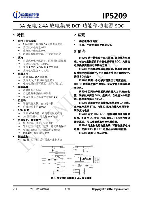
INJ4120 产品说明书

IP5358支持SCP、VOOC、双向PD3.0等全部快充协议的移动电源SOC特性•同时支持多个USB口✧2个USB A口输出✧1个USB B口输入✧1个USB C口输入/输出•快充规格✧任意一个口都支持快充✧集成QC2.0/QC3.0输出快充协议✧集成FCP输入/输出快充协议✧集成AFC输入/输出快充协议✧集成SFCP输入/输出快充协议✧集成SCP输出快充协议✧集成VOOC输出快充协议✧集成MTK PE+ 1.1&2.0输出快充协议✧集成USB C DRP协议,支持输入输出快充✧兼容BC1.2、苹果、三星手机快充•集成USB Power Delivery(PD2.0/PD3.0)协议✧支持PD2.0双向输入/输出协议✧支持PD3.0输入/输出,PPS输出协议✧支持5V,9V,12V电压档位输入✧支持5V,9V,12V电压档位输出✧PPS支持5~11V,20mV/step输出电压档位✧集成硬件的双向标记编解码(BMC)协议✧集成物理层协议(PHY)✧集成硬件CRC✧支持Hard Reset•充电规格✧电池端充电电流最高可达5.0A✧自适应充电电流调节✧支持4.20V、4.3V、4.35V、4.40V电池•放电规格✧输出电流能力:5V:3.1A 9V:2.0A 12V:1.5A✧同步开关放电5V 2A效率达95%以上✧支持线补•电量显示✧内置14bit ADC和电量计✧支持1 / 2 / 4颗LED电量显示✧支持88、188等各种数码管电量显示✧智能识别LED电量显示灯数目✧外部PIN选数码管还是LED灯做电量显示✧可自学习的电量计,电量显示更均匀✧初始电池容量PIN选配置•其他功能✧自动检测手机插入和拔出✧快充状态指示✧支持电池温度检测和PCB板温度检测✧智能识别负载,轻负载自动进待机✧支持多种按键模式选择✧内置照明灯驱动•多重保护、高可靠性✧输入过压、欠压保护✧输出过流、过压、短路保护✧电池过充、过放、过流保护✧IC过温保护✧充放电电池温度NTC保护✧ESD 4KV,输入(含CC引脚)耐压20V •BOM极简✧内置开关功率MOS、路径MOS✧单电感实现充电、放电功能•封装规格:7mm × 7mm 0.5pitch QFN48概述IP5358是一款集成QC2.0 / QC3.0/SCP/VOOC输出快充协议、FCP/AFC/SFCP输入输出快充协议、MTK PE+ 1.1&2.0输出快充协议、USB C/PD2.0/PD3.0输入输出协议、USB C PD3.0 PPS输出协议、兼容BC1.2/苹果/三星手机、同步升/降压转换器、锂电池充电管理、电池电量指示等多功能的电源管理SOC,为快充移动电源提供完整的电源解决方案。
thinkstation-p520-datasheet

The most powerful single CPU workstation — a next-generation system that packs enough punch for any job and is reliable enough for mission-critical environments. Customize a ThinkStation® P520 for the power, performance, and usability you need, including the highest number of cores and insane frequencies with the latest high-performing Intel Xeon W processors and professional NVIDIA Quadro RTX graphics.VERSATILE WORKSTATION CONFIGURED YOUR WAYFEATURESE L I A B I L I T Y, A N D P E RF O R M A N C EUp to NVIDIA® Quadro RTX™ 8000 graphics card Intel® Xeon® W Series processorUp to 1000W power supply (up to 92% efficient)ThinkStation M.2 Quad Adapter supportUp to 8 total drives for ultimate flexibilitySupport for 10GB networking¹.W .W© 2020 Lenovo. All rights reserved. These products are available while supplies last. For any questions concerning price, please contact your Lenovo Account Executive. Lenovo is not responsible for photographic or typographic errors. Warranty: For a copy of applicable warranties, write to: Warranty Information, 500 Park Offices Drive, RTP, NC 27709, Attn: Dept. ZPYA/B600. Lenovo makes no representation or warranty regarding third-party products or services. Trademarks: Lenovo, the Lenovo logo, ThinkStation, ThinkVision, and Vantage are trademarks or registered trademarks of Lenovo. Microsoft and Windows are registered trademarks of Microsoft Corporation. Intel, Xeon, Core, Thunderbolt, and Intel vPro are trademarks of Intel Corporation or its subsidiaries in the U.S. and/or other countries. Bluetooth is a trademark of its proprietor and used by Lenovo under license. ENERGY STAR is a registered trademark of the U.S. Environmental Protection Agency. The NVIDIA logo, Quadro, and RTX are trademarks and/or registered trademarks of NVIDIACorporation in the U.S. and other countries. Linux is the registered trademark of Linus Torvalds in the U.S. and other countries. USB Type-C and USB-C aretrademarks of USB Implementers Forum. Other company, product, and service names may be trademarks or service marks of others.Lenovo ™ Options & AccessoriesLenovo 16GB 2933MHz ECC RDIMM Memory NVIDIA® Quadro RTX™ 4000ThinkVision® P24q-20PERFORMANCE ProcessorIntel® Xeon® W Series Processor (up to 18 cores, up to 4.7GHz)Chipset Intel C422Operating SystemWindows 10 Pro for Workstations Ubuntu ® Linux®²Red Hat® Linux (certified)GraphicsUp to NVIDIA Quadro RTX 8000Total MemoryUp to 512GB DDR4, 2933MHz Memory DIMM Capacity 8GB / 16GB / 32GB / 64GB 8 DIMM Slots Total StorageUp to 8 total drives 3Up to 4 internal storage bays Max M.2 = 2 (4TB) Max 3.5" = 6 (36TB) Max 2.5" = 6 (12TB)Storage Type Capacity M.2 PCIe SSD up to 2TB3.5" SATA 7200rpm up to 6TB 2.5" SATA SSD up to 2TB 2.5" SATA HDD up to 500GB RAID 0/1/5/10Power Supply690W, 900W, or 1000W 92% efficientCONNECTIVITY Front Ports(4) USB 3.1 Gen 1 Type-A* (1) Mic/Headphone Combo Jack(1) Thunderbolt™ 3 Type-C 4 (1) eSATA⁴ (1) USB 3.1 Gen 1 Type-C*⁴Rear Ports(4) USB 3.1 Gen 1 Type-A* (2) USB 2.0 T ype-A (2) PS/2(1) RJ-45 Gigabit Ethernet (1) Audio Line-In (1) Audio Line-Out (1) Microphone-In(1) Serial Port¹ (1) Rear Thunderbolt Adapter 1 (1) eSATA 1WLANIntel 8265 2x2 AC + Bluetooth™ 4.2 vPro Removable Storage(1) Media Card Reader⁵ (1) Slim ODD 4(1) Front Accessible Storage Enclosure¹Expansion Slots (2) PCIe x16 Gen 3 (1) PCIe x8 Gen 3 (2) PCIe x4 Gen 3 (1) PCI SOFTWARE Lenovo Preload ⁶Lenovo Vantage Lenovo ThinkShieldDESIGNDimensions (WxDxH)(mm): 165 x 460 x 440 (inches): 6.5 x 18.1 x 17.3WeightMax configuration: 52.91lbs (24kg)ISV CERTIFICATIONSAdobe®, Autodesk®, AVID®, Altair®, AVEVA™, Bentley®, Dassault®, Nemetschek®, PTC®, Siemens®, Barco®, Eizo®, McKesson®GREEN CERTIFICATIONSENERGY STAR® 7.0EPEAT®⁷GREENGUARD® RoHS Compliant80 PLUS® Platinum – 690W, 900W, and 1000W PSUFor a full list of accessories and options, please visit: https://1 Optional2 Select versions available via preload; versions are configuration specific3 Any combination of storage to equal maximum storage drives4 Optional; available in front bay via FLEX Module5 9-in-1 standard; 15-in-1 optional6 Available with Windows 10 Operating System only7 Certification available on select models; EPEAT registered whereapplicable. EPEAT registration varies by country. See for registration status by country.* The actual transfer speed of the USB 3.1 Gen1 will vary and, depending on many factors, such as the processing capability of host and peripheral devices, file attributes and other factors related tosystem configuration and your operating environments, will be slower than a speed of 5Gbit/s.Lenovo ThinkStation® P520 Specifications。
66205-2资料

66205-2 Product DetailsHome | Customer Support | Suppliers | Site Map | Privacy Policy | Browser Support© 2008 Tyco Electronics Corporation All Rights Reserved SearchProducts Documentation Resources My Account Customer Support Home > Products > By Type > Product Feature Selector > Product DetailsNo Image Available66205-2Active Taper Pins and BlocksNot reviewed for RoHS ComplianceProduct Highlights:?Taper Pins?Pin Type = Solid?Pin Style = Standard?53 Series?Loose PieceView all Features | Find SimilarProductsCheck Pricing &AvailabilitySearch for ToolingProduct FeatureSelectorContact Us AboutThis ProductQuick LinksDocumentation & Additional InformationProduct Drawings:?PIN, TAPER, ''53'' SERIES UNINSULATED(PDF, English)Catalog Pages/Data Sheets:?None AvailableProduct Specifications:?Contact, TAYP-AIR Pins and Blocks(PDF, English)?Contact, Taper Pins(PDF, English)Application Specifications:?None AvailableInstruction Sheets:?None AvailableCAD Files:?None AvailableList all Documents Additional Information:?Product Line InformationRelated Products:?ToolingProduct Features (Please use the Product Drawing for all design activity)Product Type Features:?Product Type = Taper Pins?Insulation Support = Un-Insulated Support?Insulation Diameter (mm [in]) = 0.79 – 1.22[0.031 –0.048]?Finish = Gold (30)?Comment = For Stranded Wire Only.Body Related Features:?Pin Type = Solid?Pin Style = Standard?Series = 53?Wire Range (mm [AWG]) = 0.08-0.24²[28-24] ?Overall Length (mm [in]) = 17.27 [0.680]?Mates With = 53 Series Connector Block Industry Standards:?RoHS/ELV Compliance = Not reviewed forELV/RoHS compliance?Lead Free Solder Processes = Not reviewed forlead free solder processPackaging Related Features:?Packaging Method = Loose PieceOther:?Brand = AMPProvide Website Feedback | Contact Customer Support。
什么是PIR被动红外

什么是PIR(被动红外探测器)PIR是Passive InfraRed的缩写,就是被动红外技术,PIR探测器的全称就是Passive Infrared Detection(被动红外探测,有时候被称为Passive Infrared Sensor,在安防行业探测器多被称为Detection)。
定义一:凡是温度超过绝对0℃的物体都能产生热辐射(红外光谱),而温度低于1725°C的物体产生的热辐射光谱集中在红外光区域,因此自然界的所有物体都能向外辐射红外热,不同温度的物体,其释放的红外能量的波长是不一样的,因此红外波长与温度的高低是相关的。
而任何物体由于本身的物理和化学性质的不同、本身温度不同所产生的红外辐射的波长和距离也不尽相同,通常分为三个波段。
•近红外:波长范围0.75~3μm•中红外:波长范围3~25μm•远红外:波长范围25~1000μm人体辐射的红外光波长3~50μm,其中8~14μm占46%,峰值波长在9.5μm。
在被动红外探测器中有两个关键性的元件,一个是热释电红外传感器(PIR),它能将波长为8-12um之间的红外信号变化转变为电信号,并能对自然界中的白光信号具有抑制作用,因此在被动红外探测器的警戒区内,当无人体移动时,热释电红外感应器感应到的只是背景温度,当人体进人警戒区,通过菲涅尔透镜,热释电红外感应器感应到的是人体温度与背景温度的差异信号,因此,红外探测器的红外探测的基本概念就是感应移动物体与背景物体的温度的差异。
另外一个器件就是菲涅尔透镜,菲涅尔透镜有两种形式,即折射式和反射式。
菲涅尔透镜作用有两个:一是聚焦作用,即将热释的红外信号折射(反射)在PIR上,第二个作用是将警戒区内分为若干个明区和暗区,使进入警戒区的移动物体能以温度变化的形式在PIR上产生变化热释红外信号,这样PIR就能产生变化的电信号。
定义二:在室温条件下,任何物品均有辐射。
温度越高的物体,红外辐射越强。
Fujitsu PRAID EP520i 商品说明书
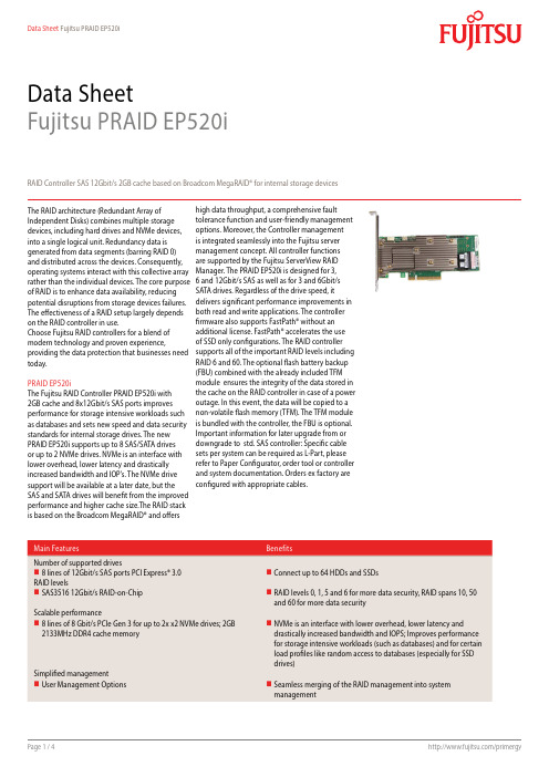
Data SheetFujitsu PRAID EP520iRAID Controller SAS 12Gbit/s 2GB cache based on Broadcom MegaRAID® for internal storage devices The RAID architecture (Redundant Array of Independent Disks) combines multiple storage devices, including hard drives and NVMe devices, into a single logical unit. Redundancy data is generated from data segments (barring RAID 0) and distributed across the devices. Consequently, operating systems interact with this collective array rather than the individual devices. The core purpose of RAID is to enhance data availability, reducing potential disruptions from storage devices failures. The effectiveness of a RAID setup largely depends on the RAID controller in use.Choose Fujitsu RAID controllers for a blend of modern technology and proven experience,providing the data protection that businesses need today.PRAID EP520iThe Fujitsu RAID Controller PRAID EP520i with2GB cache and 8x12Gbit/s SAS ports improvesperformance for storage intensive workloads such as databases and sets new speed and data security standards for internal storage drives. The newPRAID EP520i supports up to 8 SAS/SATA drivesor up to 2 NVMe drives. NVMe is an interface with lower overhead, lower latency and drasticallyincreased bandwidth and IOP’s. The NVMe drivesupport will be available at a later date, but theSAS and SATA drives will benefit from the improved performance and higher cache size.The RAID stack is based on the Broadcom MegaRAID® and offershigh data throughput, a comprehensive fault tolerance function and user-friendly management options. Moreover, the Controller management is integrated seamlessly into the Fujitsu server management concept. All controller functions are supported by the Fujitsu ServerView RAID Manager. The PRAID EP520i is designed for 3, 6 and 12Gbit/s SAS as well as for 3 and 6Gbit/s SATA drives. Regardless of the drive speed, itdelivers significant performance improvements in both read and write applications. The controller firmware also supports FastPath® without an additional license. FastPath® accelerates the use of SSD only configurations. The RAID controller supports all of the important RAID levels including RAID 6 and 60. The optional flash battery backup (FBU) combined with the already included TFM module ensures the integrity of the data stored in the cache on the RAID controller in case of a power outage. In this event, the data will be copied to a non-volatile flash memory (TFM). The TFM module is bundled with the controller, the FBU is optional.Important information for later upgrade from or downgrade to std. SAS controller: Specific cable sets per system can be required as L-Part, pleaserefer to Paper Configurator, order tool or controller and system documentation. Orders ex factory are configured with appropriate cables.Technical detailsTechnical detailsController Silicon RoC (RAID on Chip) SAS3508Adapter Type RAID 5/6 Ctrl.Operating system pre-installed Information to released operating systems can be found in the server datasheets. Details can be found in thereleased drivers list on the support portal.Released drivers list link /Download/Index.aspNumber of ports8 ports int.Connector internal2x SFF8643 (Mini-SAS HD)Data transfer rate up to12 Gbit/s; 8 Gbit/sBus type PCIe 3.0Bus width x8RAID Management ServerView RAID ManagerStorCLI (command-line interface)BIOS Configuration UtilityKey RAID Data Protection Feature- RAID levels 0, 1, 5 and 6- RAID spans 10, 50 and 60- Maximum number of spans is 8- Online Capacity Expansion (OCE)- Online RAID level Migration (RLM)- Auto resume after loss of system power during array rebuild or reconstruction (RLM)- Fast initialization for quick array setup- Load Balancing- Configurable stripe size up to 1MB- Fast initialisation for quick array setup- Check consistency for background data integrity - Make Data Consistent (MDC)- Patrol read for media scanning and repairing- Up to 64 logical drives per controller- S.M.A.R.T support- Global and dedicated Hot Spare with Revertible Hot Spare support- Automatic rebuild- Enclosure affinity- Enclosure management- SES (inband)- SGPIO (outband)RAID level0, 1, 10, 5, 50, 6, 60RAID cache backup unit Optional FBURAID controller notes based on SAS3516Interface technology SAS/SATA/PCIe-NVMeOrder code Product Name Height of bracket RAID controller cache size Number of Connectors S26361-F4042-E202PRAID EP520i Low Profile (LP) 2 GB2S26361-F4042-E2PRAID EP520i Full Height (FH) 2 GB2S26361-F4042-L502PRAID EP520i FH/LP Full Height / Low Profile 2 GB2Order code Product Name NotesS26361-F4042-E155RAID Ctrl FBU option for PRAID EP5xx with 55cm cable installed - Super-capacitor incl. cableS26361-F4042-E183RAID Ctrl FBU option for PRAID EP5xx with 83cm cable installed - Super-capacitor incl. cableinstalled - Super-capacitor incl. cableS26361-F4042-E171RAID Ctrl FBU option for PRAID EP5xx with 70cm cable forRX4770 M4S26361-F4042-L110RAID Ctrl FBU option for PRAID EP5xx with 25,55,83cm cable installed - Super-capacitor incl. cableinstalled - Super-capacitor incl. cableS26361-F4042-L113RAID Ctrl FBU option for PRAID EP5xx with 70cm cable forRX4770ComplianceCompliance notes According to the corresponding system Compliance link https:///sites/certificatesContactFujitsu LimitedWebsite: /primergy2023-11-27 WW-ENworldwide project for reducing burdens on the environment.Using our global know-how, we aim to contribute to the creation of a sustainable environment for future generations through IT.Please find further information at http://www./global/about/environmenttechnical specification with the maximum selection of components for the named system and not the detailed scope ofdelivery. The scope of delivery is defined by the selection of components at the time of ordering. The product was developed for normal business use.Technical data is subject to modification and delivery subject to availability. Any liability that the data and illustrations are complete, actual or correct is excluded. Designations may be trademarks and/or copyrights of the respective owner, the use of which by third parties for their own purposes may infringe the rights of such owner.More informationAll rights reserved, including intellectual property rights. Designations may be trademarks and/or copyrights of therespective owner, the use of which by third parties for their own purposes may infringe the rights of such owner. For further information see https:///global/about/resources/terms/ Copyright 2023 Fujitsu LIMITED。
INFINEON IPP50R520CP 数据手册

IPP50R520CPMaximum ratings, at T j =25 °C, unless otherwise specified ParameterSymbol Conditions Unit Continuous diode forward current I S ADiode pulse current2)I S,pulse 15Reverse diode d v /d t 4)d v /d t15V/nsParameter Symbol ConditionsUnitmin.typ.max.Thermal characteristicsThermal resistance, junction - case R thJC -- 1.9K/WR thJAleaded--62Soldering temperature,wavesoldering only allowed at leadsT sold 1.6 mm (0.063 in.) from case for 10 s--260°CElectrical characteristics, at T j =25 °C, unless otherwise specified Static characteristicsDrain-source breakdown voltage V (BR)DSS V GS =0 V, I D =250 µA 500--VGate threshold voltageV GS(th)V DS =V GS , I D =0.25 mA 2.533.5Zero gate voltage drain current I DSS V DS =500 V, V GS =0 V, T j =25 °C--1µAV DS =500 V, V GS =0 V, T j =150 °C-10-Gate-source leakage current I GSS V GS =20 V, V DS =0 V --100nA Drain-source on-state resistanceR DS(on)V GS =10 V, I D =3.8 A, T j =25 °C-0.470.52ΩV GS =10 V, I D =3.8 A, T j =150 °C- 1.2-Gate resistanceR Gf =1 MHz, open drain-2.2-ΩValues Thermal resistance, junction - ambientValue T C =25 °C3.8IPP50R520CPParameterSymbol ConditionsUnitmin.typ.max.Dynamic characteristics Input capacitance C iss -680-pFOutput capacitanceC oss-31-Effective output capacitance, energyrelated 5)C o(er)-29-Effective output capacitance, time related 6)C o(tr)-63-Turn-on delay time t d(on)-35-nsRise timet r -14-Turn-off delay time t d(off)-80-Fall timet f-17-Gate Charge Characteristics Gate to source charge Q gs -3-nCGate to drain charge Q gd -5-Gate charge total Q g -1317Gate plateau voltage V plateau-5.2-VReverse Diode Diode forward voltage V SD V GS =0 V, I F =3.8 A, T j =25 °C-0.9 1.2V Reverse recovery time t rr -240-ns Reverse recovery charge Q rr - 1.6-µC Peak reverse recovery currentI rrm-13-A1)J-STD20 and JESD222)Pulse width t p limited by T j,max3)Repetitive avalanche causes additional power losses that can be calculated as P AV =E AR *f.6)C o(tr) is a fixed capacitance that gives the same charging time as C oss while V DS is rising from 0 to 80% V DSS.4)I SD ≤I D , d i /d t ≤400A/µs, V DClink =400V, V peak <V (BR)DSS , T j <T jmax , identical low and high side switchV R =400 V, I F =I S , d i F /d t =100 A/µs5)C o(er) is a fixed capacitance that gives the same stored energy as C oss while V DS is rising from 0 to 80% V DSS.Values V GS =0 V, V DS =100 V, f =1 MHzV DD =400 V,V GS =10 V, I D =3.8 A, R G =48.3 ΩV DD =400 V, I D =3.8 A, V GS =0 to 10 VV GS =0 V, V DS =0 V to 400 V1 Power dissipation5 Typ. output characteristics9 Typ. gate charge13 Typ. capacitancesIPP50R520CP Definition of diode switching characteristicsIPP50R520CP PG-TO220-3-1/PG-TO220-3-21: OutlineIPP50R520CPPublished byInfineon Technologies AG81726 Munich, Germany© 2007 Infineon Technologies AGAll Rights Reserved.Legal DisclaimerThe information given in this document shall in no event be regarded as a guarantee ofconditions or characteristics. With respect to any examples or hints given herein, any typicalvalues stated herein and/or any information regarding the application of the device,Infineon Technologies hereby disclaims any and all warranties and liabilities of any kind,including without limitation, warranties of non-infringement of intellectual property rightsof any third party.InformationFor further information on technology, delivery terms and conditions and prices, pleasecontact the nearest Infineon Technologies Office().WarningsDue to technical requirements, components may contain dangerous substances. For informationon the types in question, please contact the nearest Infineon Technologies Office.Infineon Technologies components may be used in life-support devices or systems only withthe express written approval of Infineon Technologies, if a failure of such components canreasonably be expected to cause the failure of that life-support device or system or to affectthe safety or effectiveness of that device or system. Life support devices or systems areintended to be implanted in the human body or to support and/or maintain and sustainand/or protect human life. If they fail, it is reasonable to assume that the health of the useror other persons may be endangered.。
BFS520,115;BFS520,135;中文规格书,Datasheet资料
handbook, halfpage
50 gain (dB) 40
MRC024
MRC025
handbook, halfpage
50
G UM
gain (dB) 40 G UM
30 MSG 20 G max
30
MSG
20 G max 10
10
0 10−2
10−1
1
f (GHz)
10
0 1 halfpage
200
h FE 150
200
100
100
50
0 0 50 100 150 T ( o C) s 200
0 10−2
10−1
1
10 I C (mA)
102
VCE = 6 V; Tj = 25 C.
Fig.2 Power derating curve.
Fig.3
DC current gain as a function of collector current.
DISCRETE SEMICONDUCTORS
DATA SHEET
BFS520 NPN 9 GHz wideband transistor
Product specification September 1995
/
NXP Semiconductors
Product specification
handbook, halfpage handbook, halfpage
MRC027
BFS520
20
G UM (dB)
25 gain (dB) 20
MRC026
MSG 18 15 16 VCE = 6 V 10 3V 14 5 12 0 10 0 10 20 I C (mA) 30
cp50
CP50硬件结构-GESB
1:每个GESB板上有8 个相同千兆以太端口
CP50硬件结构-网络
CP50硬件结构-网络
1 CP之间通信
首选本端GESB,次选对端GESB
2 RPB-E到CP通信
每个RP都同CP建立通信,上行同时发出信号。(下行?)。同串行 RPS不一样。
3 CPT通信
正常:APG-主用CP的GESB-主用UPBB-备用UPBB-备用GESB-备用 CP 异常:APG-备用CP的GESB-备用UPBB-备用CP
4:定义BSC
MGBSC,MGBSC源自5:注意在MSC中使用TID,和MGW中具体设备关联,将TID分解为二进制后, 可以得出MGW中的中继、时隙(类型华为TID-CIC转换表)
CP50数据制作-Pool MSC定义
1:TMSI重分配及结构改变
2B-4B,引入NRI和TMSI GENE 一些重要AXEPARS参数 MGNDL指派NRI长度和参数值
CP50培训
• CP50硬件结构
1 2 3 4 5 6 总体介绍 整体结构 单板 内存 以太RP 网络
• CP50数据制作
1 2 3 4 MGW定义 BSC定义 SIGTRAN定义 MSC POOL
CP50硬件结构-总体
• 平台
HW:HP CX2620 ;SW:LINUX
• 处理能力
以33为基数,CP40为1.9,CP50为3.8
CP50数据制作-SIGTRAN定义
1:用GARP实现宽带信令, 2:不需要GSS部分 3:可以和ST共存 4:相关指令 IHCOI:IPPORT=IP-0-2,IPADDR=
CP50数据制作-BSC定义
1:定义MGW 2:定义MGG 3:定义REMOTE设备
IRF520NPBF;中文规格书,Datasheet资料

The TO-220 package is universally preferred for all commercial-industrial applications at power dissipation levels to approximately 50 watts. The low thermal resistance and low package cost of the TO-220 contribute to its wide acceptance throughout the industry.
IDSS
Drain-to-Source Leakage Current
IGSS
Qg Qgs Qgd td(on) tr td(off) tf
Gate-to-Source Forward Leakage Gate-to-Source Reverse Leakage Total Gate Charge Gate-to-Source Charge Gate-to-Drain ("Miller") Charge Turn-On Delay Time Rise Time Turn-Off Delay Time Fall Time
––– ––– 25 ––– ––– 250
µA VDS = 100V, VGS = 0V VDS = 80V, VGS = 0V, TJ = 150°C
––– ––– 100 nA VGS = 20V
––– ––– -100
VGS = -20V
––– ––– 25
ID = 5.7A
––– ––– 4.8 nC VDS = 80V
20µs PULSE WIDTH
1
TC = 175°C
PRFS-P2020-005中文资料
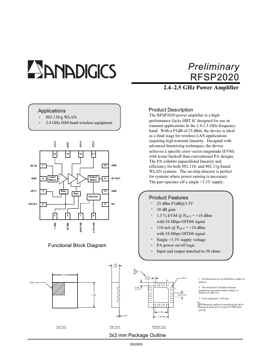
Preliminary RFSP20202.4–2.5 GHz Power AmplifierProduct DescriptionThe RFSP2020 power amplifier is a high-performance GaAs HBT IC designed for use in transmit applications in the 2.4-2.5 GHz frequency band. With a P1dB of 25 dBm, the device is ideal as a final stage for wireless LAN applications requiring high transmit linearity. Designed with advanced linearizing techniques, the deviceVCC1VCC2VCC3GNDRFSP20202.4–2.5 GHz Power AmplifierNote 1: Test Conditions: V CC = 3.3V, Freq. = 2450 MHz, T =25°C, Small S ignal Con ditions unless otherwise stated. Note 2: Increase in EVM o ver system EVM floor.Note 3: Load VSWR is set to 7:1 and the angle is varied 360 degrees.NOTESANADIGICS, Inc.141 Mount Bethel RoadWarren, New Jersey 07059,U.S.A.Tel: +1(908)668-5000Fax: +1(908)668-5132URL: E-mail: Mktg@IMPORTANT NOTICEANADIGICS,Inc.reserves the right to make changes to its products or to discontinue any product at any time without notice.The product specifications contained in Advanced Product Information sheets and Preliminary Data Sheets are subject to change prior to a product’s formal rmation in Data Sheets have been carefully checked and are assumed to be reliable;however,ANADIGICS assumes no responsibilities for inaccuracies.ANADIGICS strongly urges customers to verify that the information they are using is current before placing orders.WARNINGANADIGICS products are not intended for use in life support appliances,devices or e of an ANADIGICS product in any such application。
NC5200C交换设备

IBM_小型机P520_AIX5.3操作系统安装指导书-华为资料

资料编码... 产品名称IBM小型机P520使用对象培训工程师产品版本版本V5.3编写部门VAS 资料版本V1.0-20060718培训环境IBM 小型机P520 AIX5.3操作系统安装指导书V1.0-20060718拟制:才天恒日期:20060718审核:才天恒日期:20060718审核:日期:批准:日期:华为技术有限公司版权所有侵权必究目录第1章软件相关概念 (5)1.1 基本介绍 (5)1.2 重要概念介绍 (5)1.2.1软件产品的命名格式: (5)1.2.2 FILE_SET (5)1.2.3 PACKAGE (5)1.2.4 LPP (6)1.2.5 ML (6)1.2.6 RML (6)1.2.7 PTF & APAR (7)第2章软件安装和配置 (8)2.1 软件安装前提 (8)2.2 操作系统软件安装过程 (8)2.2.1 安装基本操作系统包(BOS) (8)2.2.2 系统自动重启,并自动运行配置助手 (21)2.2.3 补充安装需要的包 pakage (28)2.2.4 安装 RML(ML) 推荐维护包 (维护包) (33)2.2.5 安装必要的APAR 以及 PTF(instfix –I ,smitty update_all) (39)2.2.6 系统备份mksysb –i /dev/rmt0 (39)2.2.7 重启系统 (39)2.3 安装HACMP 机群软件 (39)2.3.1 安装HACMP软件(smitty installp) (39)2.3.2 安装HACMP软件补丁包(smitty installp) (40)2.3.3 安装成功后再次系统备份mksysb –i /dev/rmt0 (40)2.3.4 重启系统 (40)2.4 AIX操作系统配置 (41)安装完成后,需要完成后续配置工作: (41)本部分内容仅供参考,具体实施请参考各产品的安装手册 (41)2.4.1 修改主机名 (41)2.4.2 修改时间 (41)2.4.3 检查网卡及设置 IP地址 (41)2.4.4 如何做根盘镜象: (41)2.4.5 如何将操作系统内核改为64Bit (42)2.4.6 如何清除小型机上由于告警造成的黄灯 (42)2.4.7 如何修改系统参数 (42)设置用户license数 (42)2.4.8 如何使64位应用环境生效 (43)2.4.9 如何修改每个用户使用的最大进程数和IO参数 (43)2.4.10 如何修改异步IO参数 (44)2.4.11 如何修改/etc/security/limits文件 (45)2.4.12 如何设置本地磁盘空间 (46)2.4.13 如何设置PAGINGSPACE (47)2.4.14 如何设置系统提示符带主机名及路径 (47)2.4.15 如何CDE配置环境 (47)第3章常用命令 (47)第4章常用网址 (48)关键词:AIX 安装指导书摘要:缩略语清单:参考资料清单:《AIX 5L 系统管理技术》电子工业出版社IBM 小型机操作系统安装指导书第1章软件相关概念1.1 基本介绍AIX 操作系统系统是 IBM 公司专为 IBM pSeries 和 RS6000服务器开发的unix操作系统。
A2550N中文资料
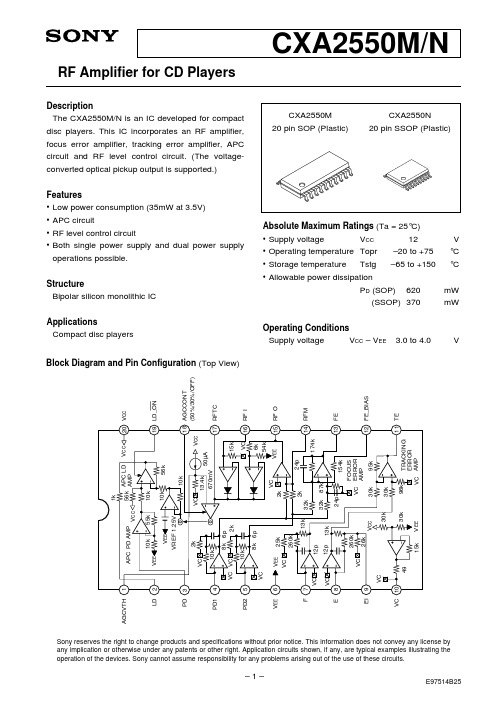
Maximum output amplitude L
V13-5
O
O
13
Maximum output amplitude H
V13-6
O
O
14
Offset voltage 1 V11-1
15
Voltage gain 1
V11-2
O
16
Voltage gain 2
V11-3
O
300mV 300mV
TE amplifier
23
Maximum output amplitude
V2-5 O
OO OO
1V 1V 450µA 570µA 0µA 0.8mA 0µA
2.7V 2.7V 2.7V 2.7V
Description of I/O waveform Min. Typ. Max. Unit
E4
and measurement method
20 Input GND
6.37 9.8 13.23 mA
6 Input GND
–13.23 –9.8 –6.37 mA
15
Input resistance 33kΩ
Output DC measurement
–50.0
–10
60.0
mV
15
Input 1kHz 120mVp-p
Output AC measurement
V15-5
OO
O
8
Offset voltage
V13-1
9
Voltage gain 1
V13-2
O
10
Voltage gain 2
V13-3
O
IP5209 datasheet v1.0 2A充电,2A放电
L2 亮 亮 亮 灭 灭 灭
L3 亮 亮 灭 灭 灭 灭
L4 亮 灭 灭 灭 灭 灭
灭
V1.0
Tel:13510832836
7 / 13
Copyright © 2014, Injoinic Corp.
IP5209
充电模式 4 颗 LED 显示 电量 C(%) 充满 75%≤C 50%≤C<75% 25%≤C<50% C<25% L1 亮 亮 亮 亮
按键
KEY
图 3 KEY 按键
按键连接方式如图 2 所示, 可识别长按键和短按键操作。 按键持续时间长于 30ms,但小于 2s, 即为短按动作,短按会打开电量显示灯和升压输出。 按键持续时间长于 2s, 即为长按动作, 长按会开启或者关闭照明 LED。 小于 30ms 的按键动作不会有任何响应。 在 1s 内连续两次短按键,会关闭升压输出、电量显示和照明 LEz 闪烁
L3 亮 亮
1.5Hz 闪烁
L4 亮
1.5Hz 闪烁
灭 灭 灭
灭 灭
灭
三灯、五灯的显示方式和四灯类似,每颗灯对应的电池电量如下表 D1 D2 D3 D4 D5
三颗灯 四颗灯 五颗灯
3% 25% 20%
66% 50% 40%
100% 75% 60%
无 100% 80%
IP5101 IP5105 IP5206 IP5108 IP5109 IP5209 IP5209S
V1.0
Tel:13510832836
3 / 13
Copyright © 2014, Injoinic Corp.
IP5209
6 极限参数
参数 端口输入电压范围 工作环境温度范围 结温范围 存储温度范围 热阻(结温到环境) 人体模型(HBM) 符号 VIN TA TJ Tstg θJA ESD 值 -0.3 ~ 5.5 0 ~ 70 -40 ~ 150 -60 ~ 150 40 4 单位 V ℃ ℃ ℃ ℃/W KV
CP50中文翻译版
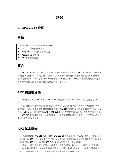
CP501、APZ 212 50介绍目标简介APZ 212 50是AXE 10的控制系统,重点关注的是高端容量。
APZ 212 50是为实现更大处理能力的交换节点而提供的。
它利用中央处理器中的高速以太连接来连接I/O和处理器。
这种处理器集成了英特尔的Itanium处理器和HP的运行在Linux上的便携式级别的服务器,再整合爱立信的通信功能从而为未来提供了一个平台。
APZ的演变发展第一代的APZ是APZ 210,从APZ 210 03演变到210 04,最后在1970年代演变为APZ 210 06。
为了提供应用系统的容量例如转接局和国际交换局从而产生了比APZ 210更强的APZ 212处理器。
但是,并不是所有的交换机都需要比APZ 210所可以提供的更多的处理能力。
于是产生了APZ 211。
这种类型的APZ与APZ 210相比没有提供更高处理能力但是生产成本更低。
APZ 212仍在不断发展。
无论处理能力还是存储容量都获得了引人注目的提高,从而产生了今天的超强处理器。
APZ基本概念中央处理器的APZ 212系列一直到APZ 212 33(本章简称传统APZ)都基于专用的平台和操作系统。
APZ 212 40在引入硬件和unix作为操作系统方面等两方面向公开平台迈出了巨大的步伐。
APZ 212 50是继APZ 212 40之后的第二代商用处理器。
虽然APZ的平台有所改变但是一些基本的概念仍保留一样。
APZ 212系列的处理器到APZ 212 33的物理组成都分成独立的两部分单元,分别是指令处理单元(IPU)和信号处理单元(SPU)。
两部分处理单元运行的操作系统主要都由微程序组成,MIP。
SPU根据它们的优先级别分配由应用单元产生的进程,然后由IPU协调执行。
当执行进程的时候IPU会使用存储在程序各自的数据存储中的应用代码和数据内容。
AXE的硬件和软件设备及单元定义在核心软件中。
传统APZ 212系列的核心软件在PLEX中编码然后在转载入APZ前编译成ASA。
- 1、下载文档前请自行甄别文档内容的完整性,平台不提供额外的编辑、内容补充、找答案等附加服务。
- 2、"仅部分预览"的文档,不可在线预览部分如存在完整性等问题,可反馈申请退款(可完整预览的文档不适用该条件!)。
- 3、如文档侵犯您的权益,请联系客服反馈,我们会尽快为您处理(人工客服工作时间:9:00-18:30)。
IPP50R520CPMaximum ratings, at T j =25 °C, unless otherwise specified ParameterSymbol Conditions Unit Continuous diode forward current I S ADiode pulse current2)I S,pulse 15Reverse diode d v /d t 4)d v /d t15V/nsParameter Symbol ConditionsUnitmin.typ.max.Thermal characteristicsThermal resistance, junction - case R thJC -- 1.9K/WR thJAleaded--62Soldering temperature,wavesoldering only allowed at leadsT sold 1.6 mm (0.063 in.) from case for 10 s--260°CElectrical characteristics, at T j =25 °C, unless otherwise specified Static characteristicsDrain-source breakdown voltage V (BR)DSS V GS =0 V, I D =250 µA 500--VGate threshold voltageV GS(th)V DS =V GS , I D =0.25 mA 2.533.5Zero gate voltage drain current I DSS V DS =500 V, V GS =0 V, T j =25 °C--1µAV DS =500 V, V GS =0 V, T j =150 °C-10-Gate-source leakage current I GSS V GS =20 V, V DS =0 V --100nA Drain-source on-state resistanceR DS(on)V GS =10 V, I D =3.8 A, T j =25 °C-0.470.52ΩV GS =10 V, I D =3.8 A, T j =150 °C- 1.2-Gate resistanceR Gf =1 MHz, open drain-2.2-ΩValues Thermal resistance, junction - ambientValue T C =25 °C3.8IPP50R520CPParameterSymbol ConditionsUnitmin.typ.max.Dynamic characteristics Input capacitance C iss -680-pFOutput capacitanceC oss-31-Effective output capacitance, energyrelated 5)C o(er)-29-Effective output capacitance, time related 6)C o(tr)-63-Turn-on delay time t d(on)-35-nsRise timet r -14-Turn-off delay time t d(off)-80-Fall timet f-17-Gate Charge Characteristics Gate to source charge Q gs -3-nCGate to drain charge Q gd -5-Gate charge total Q g -1317Gate plateau voltage V plateau-5.2-VReverse Diode Diode forward voltage V SD V GS =0 V, I F =3.8 A, T j =25 °C-0.9 1.2V Reverse recovery time t rr -240-ns Reverse recovery charge Q rr - 1.6-µC Peak reverse recovery currentI rrm-13-A1)J-STD20 and JESD222)Pulse width t p limited by T j,max3)Repetitive avalanche causes additional power losses that can be calculated as P AV =E AR *f.6)C o(tr) is a fixed capacitance that gives the same charging time as C oss while V DS is rising from 0 to 80% V DSS.4)I SD ≤I D , d i /d t ≤400A/µs, V DClink =400V, V peak <V (BR)DSS , T j <T jmax , identical low and high side switchV R =400 V, I F =I S , d i F /d t =100 A/µs5)C o(er) is a fixed capacitance that gives the same stored energy as C oss while V DS is rising from 0 to 80% V DSS.Values V GS =0 V, V DS =100 V, f =1 MHzV DD =400 V,V GS =10 V, I D =3.8 A, R G =48.3 ΩV DD =400 V, I D =3.8 A, V GS =0 to 10 VV GS =0 V, V DS =0 V to 400 V1 Power dissipation5 Typ. output characteristics9 Typ. gate charge13 Typ. capacitancesIPP50R520CP Definition of diode switching characteristicsIPP50R520CP PG-TO220-3-1/PG-TO220-3-21: OutlineIPP50R520CPPublished byInfineon Technologies AG81726 Munich, Germany© 2007 Infineon Technologies AGAll Rights Reserved.Legal DisclaimerThe information given in this document shall in no event be regarded as a guarantee ofconditions or characteristics. With respect to any examples or hints given herein, any typicalvalues stated herein and/or any information regarding the application of the device,Infineon Technologies hereby disclaims any and all warranties and liabilities of any kind,including without limitation, warranties of non-infringement of intellectual property rightsof any third party.InformationFor further information on technology, delivery terms and conditions and prices, pleasecontact the nearest Infineon Technologies Office().WarningsDue to technical requirements, components may contain dangerous substances. For informationon the types in question, please contact the nearest Infineon Technologies Office.Infineon Technologies components may be used in life-support devices or systems only withthe express written approval of Infineon Technologies, if a failure of such components canreasonably be expected to cause the failure of that life-support device or system or to affectthe safety or effectiveness of that device or system. Life support devices or systems areintended to be implanted in the human body or to support and/or maintain and sustainand/or protect human life. If they fail, it is reasonable to assume that the health of the useror other persons may be endangered.。
