声光报警控制说明书
AL120 声光报警器 用户手册说明书

产品描述与应用应用于工程机械(行车、履带吊、轮胎吊等)、港口机械(门吊、桥吊等)等起重设备及皮带传送机等物料传输设备。
O 密封性能良好,具有很好的防水防尘功能。
O 灯管使用高亮度RGB ,使用寿命超过10万小时。
O 灯罩采用PC 料,有特别好的抗冲击强度、热稳定性和光泽度。
O 专用集成芯片设计,超强的电磁抗干扰性能。
O 工业级微型芯片设计,综合多种音调于一体,根据不同场所可选择对应所需的音调,以此可扩大产品的应用领域。
功能特性电气参数机械结构参数工作电压 DC18~48V/AC100~240V 壳体材质 PC/ABS 电源频率 50Hz/60Hz 灯罩材质 PC 额定功率 <45W颜色红色●音调U 盘自定义 防护等级 IEC60529 IP65 单/双语音 U 盘自定义 工作温度Ta-30 C ~+55 C 示警方式 声光分开调节 工作环境湿度 10%~95%RH声 级 >120dB(max) 安装方式 墙面安装/墙面安装(带支架)/地面安装 光源类型 LED 进线方式 填料函M20(φ6-12.5) 颜 色 RGB参考重量 3Kg 光源寿命100,000h主要技术参数Specifications墙面安装墙面安装墙面安装(带支架)地面安装安装尺寸图(单位:mm )工作模式及接线示意图示警灯控制及指示部分颜色选择拨码(表1)盘插口(注)闪烁方式选择拨码(表)音调选择拨码(表)语音忙指示灯系统工作指示灯语音下载按键(注)音量选择拨码(注)系统电源指示灯音调外部调节(表)选择拨码拨码方法灯灭带有color标示的拨码红色带有color标示的拨码蓝色带有color标示的拨码酒红色带有color标示的拨码绿色带有color标示的拨码黄色带有color标示的拨码青色带有color标示的拨码白色带有color标示的拨码选择拨码拨码方法带有Flash标示的拨码闪烁方式1:常亮带有Flash标示的拨码闪烁方式:连续闪烁带有Flash标示的拨码闪烁方式:间隔闪烁带有Flash标示的拨码闪烁方式:旋转·ExSelect1(NC)ExSelect2(NC)ExSelect1(24V)ExSelect2(NC)ExSelect1(NC)ExSelect2(24V)ExSelect1(24V)ExSelect2(24V)Tone标示的拨码(出厂默认)音调/语音1(音调和语音内容详见附表1,2)音调/语音2(音调和语音内容详见附表1,2)音调/语音3(音调和语音内容详见附表1,2)静音Tone标示的拨码音调/语音2(音调和语音内容详见附表1,2)音调/语音3(音调和语音内容详见附表1,2)音调/语音4(音调和语音内容详见附表1,2)静音Tone标示的拨码音调/语音3(音调和语音内容详见附表1,2)音调/语音4(音调和语音内容详见附表1,2)音调/语音5(音调和语音内容详见附表1,2)静音Tone标示的拨码音调/语音4(音调和语音内容详见附表1,2)音调/语音5(音调和语音内容详见附表1,2)音调/语音6(音调和语音内容详见附表1,2)静音Tone标示的拨码音调/语音5(音调和语音内容详见附表1,2)音调/语音6(音调和语音内容详见附表1,2)音调/语音7(音调和语音内容详见附表1,2)静音Tone标示的拨码音调/语音6(音调和语音内容详见附表1,2)音调/语音7(音调和语音内容详见附表1,2)音调/语音8(音调和语音内容详见附表1,2)静音以此类推,出厂共设置32种(6,7,8三路拨码是为扩展预留)以上类推以上类推以上类推静音注1:语音下载方法,此功能用于客户临时需修改语音所使用的。
声光报警器说明书
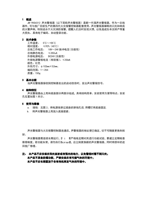
1 概述JB-YKS4312声光警报器(以下简称声光警报器)是新一代强声光警报器,作为一总线器件,可与我厂目前生产的第四代火灾报警控制器配套使用。
声光警报器耀眼的闪光和响亮的火警声响,特别适合于火灾消防报警,提醒人们及时发现火情,以免造成生命及财产等重大损失。
具有电子编码、自动登录功能。
2 技术参数工作温度: 0℃~+55℃相对湿度: ≤92%(40℃)总线工作电压: 18V ~24V 脉冲电压(无极性)总线静态电流: ≤350uA外部电源电压: DC24V(无极性)外部电源警报电流(有效值):≤50mA颜色:红色外形尺寸:φ102mm ×52mm 。
编码范围:1~254质量:150g3 基本功能当声光警报器接收到控制器发出的启动信息时,发出声光警报信号。
4 结构特征声光警报器由上壳和底座部分两部分组成,具有结构简单、安装使用方便等特点。
安装孔位置如图1所示。
5 使用与维修a. 接线: 见图2。
将电源线穿过底座的穿线孔后,用螺钉将底座固定.b. 将声光警报器上壳放入底座旋紧。
声光警报器与火灾报警控制器连通后,声警报器的地址便已确定,切不可随意更换和拆卸。
要建立定期检查维修制度,若功能失常,应立刻更换新的声光警报器,同时将损坏的送回我厂修理。
注: 本产品不应安装在阳光直射或有强光的地方,以免警报时看不到闪光;本产品不具备防爆功能,严禁安装在有可燃气体的环境中;本产品不应长期置放于含有有机挥发气体的环境中。
图2 23图1JB-YKS4312声光警报器使用说明书–)营口新山鹰报警设备有限公司。
串口语音报警灯YX2071使用说明V1.0
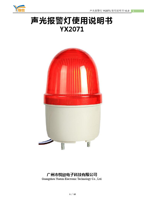
声光报警灯使用说明书YX2071广州市悦欣电子科技有限公司Guangzhou Yuexin Electronic Technology Co., Ltd.1、概述YX0271声光报警器用于在事故现场的声音报警和闪光报警,多种功作方式,只要触发即发出闪光信号和大于85dB的声报警信号,让现场人员迅速知道现场已发生事故或设备故障提示,尽快采取相应措施,避免产生重大人员、财物损失。
可应用在所有AC220V(配合电源适配器)或DC6V-30V电压工作的报警控制系统、安防监控报警系统及其他报警系统中。
2、特征✧采用悦欣研制的MP3芯片作为CPU控制核心,声音还原清晰;✧多种供电方式,DC6V-DC30V供电,可外接适配器AC220V供电等;✧硬件调节音量,可以断电记忆播放音量级别;✧通过控制模块可接入编码/模拟量火灾报警控制系统中。
✧通过智能控制模块可接入分布智能火灾自动报警控制系统中。
✧具有低功耗、长寿命、安装灵活、方便等特点。
✧支持USB自行下载声音,可以设定单次播放或循环播放;✧支持6路开关量、RS485控制和串口232控制。
3、技术参数4、产品尺寸:5、产品接线方式:产品有多种控制方式,不同方式接线参考(下图为基本接法,用户可根据实际条件更改接线方法)(1)通电就响:简单来说,通电即报警的方式是接线最方便的一种方式。
用户只需要控制设备的通断电即可实现开启或关闭报警器,很方便!但这种方式只能控制一种报警声音。
(2)四路报警模式及接线方法:报警器多路触发模式为低电平或开关量触发。
最多可实现4段不同声音的开启或关闭报警器,这种方法常用于接在PLC自动报警或接在常开开关上便于手动控制不同声音。
(3)串口RS232控制方式:串口RS232出厂带DB9针接口,直接接入PC配合相应软件或接入单片机即可使用。
(4)串口RS485控制方式:串口RS485出厂带A+/B-两线,可接入各种工控系统,实现多设备多功能报警。
SG-991 型火灾声光警报器说明书
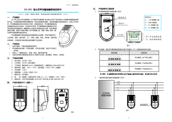
版本号:2026100811 SG-991 型火灾声光警报器使用说明书------ 安装、使用产品前,请详细阅读产品使用说明书 -----一、 产品概述SG-991型火灾声光警报器(以下简称声光警报器)是与我公司生产的总线型火灾报警控制器配套使用的产品。
声光警报器采用微处理器控制,能与控制器实时通讯,接收控制器给出的控制命令。
巡检工作状态时,声光警报器的红色状态指示灯闪烁;当事故发生时,声光警报器接收到控制器的启动命令后动作,状态指示灯常亮,声光警报器发出耀眼的闪光信号和刺耳的声报警信号,提醒现场人员迅速了解现场发生火警,尽快采取措施进行疏散,避免产生重大事故。
按下控制器上的“消音”键或“复位”键,可使声光警报器恢复监视状态。
声光警报器用于事故现场的声音报警和闪光报警,可用于高层住宅、公共场所、酒店、娱乐场所、工厂、商场、医院、学校、写字楼、证券交易所等场所,尤其适用于能见度低或有烟雾产生的场所。
二、 产品特点9 全电子编码,可通过编码器现场改写。
9 声光警报自由设置,可同时报警,也可独立报警,适应于不同的工作环境。
9 采用上、下盖结构设计,安装、调试、维护简单方便。
9光显示采用多只超高亮红色发光二极管作为光源,显示醒目、寿命长、功耗低。
三、 产品技术参数1. 执行标准:GA385- 20022. 工作电压:DC24V(脉冲调制)3. 工作电流:静态电流≤1mA(总线消耗电流),报警电流≤120mA@DC24V4. 使用环境:温度:-10℃~+55℃,相对湿度:≤95%(40℃ 无凝露)5. 闪光频率:1次/S6. 报警音量:>85dB(正前方3米)7. 编码方式:电子编码8. 线 制:四线制,无极性信号二总线(L1、L2)+电源线(+24V、GND) 9. 配接主机:9000系列控制器(如JB-QTL-9000或JB-QBL-MN/300)等四、 产品外观及尺寸(见图1)图1五、 产品使用与工程应用1. 声光警报器后盖示意图如图2所示:1 6图22. 声光选择:通过声光警报器后面调试孔盖下的跳线(JP1)按跳线说明进行选择。
南华AL600U声光报警器说明书

AL600U 声光报警器 说明书 AL600U-C1-V12应用领域应用于工程机械(行车、履带吊、轮胎吊等)、港口机械(门吊、桥吊等)等起重设备,作为设备的声光警示装置;亦可用于厂房、电气房等作为声光警报装置;也可以作为各种报警信号的终端装置。
主要功能及特点 •多种音调手动可调,报警声音响亮。
•示警灯采用超亮发光二极管,亮度高,警示效果好,使用寿命长。
•可选择报警音调与示警灯一体工作,也可选择声、光分开报警。
•可根据实际需要特制音调或语音内容(不同型号)。
安装使用方法•请务必检查报警器铭牌所示的额定电压,确认供电电源与其相符。
•报警器用4个M6的螺丝与安装面固定,安装面应平整和有足够的机械强度。
•打开铭牌盖板,将电源线(和控制线)从填料函中接入。
•接入电源和控制线后,检查接线正确无误,启动电源,报警器开始报警。
•可依照音调调节说明调节音调,先断开电源,用螺丝刀拨动拨码开关,然后上电试听。
音调调节方法•产品接线柱右边有预留拨码开关的, 才具有调节音调功能。
.•调节音调时, 应用一字螺丝刀操作, 注意手指勿触碰线路板上任何元件和走线, 以免触电.•调节音调时,拨码朝上/朝下应拨到位, 否则可能达不到预定音调.•请参照下表拨动拨码开关。
专利号ZL 2012 3 0648310.6安装尺寸图(单位:mm )接线端子图例声、光一体报警接线图例声、光分开报警接线图例本例图拨码值:00 001声压温度曲线图紧急材质部件(如灯罩、壳体),不能与工业酒精、香蕉水、异丙醇、四氯化碳、环已酮等。
北大青鸟火灾声光警报器安装使用说明书
JBF4374-Ex 火灾声光警报器安装使用说明书一.概述JBF4374-Ex型火灾声光警报器为隔爆型,可发出周期性的变调声响和闪烁光信号提示火警。
该产品外壳材料为铝合金,LED灯罩为PC材质,整个产品密封,具有防尘、防水功能,防护等级达到IP66。
防爆性能符合GB 3836.1-2010《爆炸性环境第1部分:设备通用要求》、GB 3836.2-2010《爆炸性环境第2部分:由隔爆外壳“d”保护的设备》、GB 3836.4-2010《爆炸性环境第4部分:由本质安全型“i”保护的设备》,防爆标志为Exd ib IIC T6 Gb,适用于含有II类A、B、C级T1~T6组可燃气体或蒸汽与空气形成的爆炸性混合物的1区、2区危险场所;有关技术资料、图样和样机均经国家防爆电气产品质量监督检验测试中心(CQST)审查检验合格。
JBF4374-Ex型火灾声光警报器的连接电缆或导线需选用具有防爆合格证书的连接配件引入及连接,连接时应采取措施防止电缆受力或扭转时损坏接线端子;根据防爆场所实际情况,可选择墙壁安装或管道安装方式,安装时,产品外壳需就近连接大地。
认证证书编号为:CNEx18.2539X。
1. 产品特点1.1 内置微处理器。
1.2 采用SMT表面贴装工艺。
1.3 可设置为编址型和非编址型两种工作模式。
1.4 需选用具有防爆合格证书的连接配件引入及连接。
2. 主要用途2.1 火灾声光警报器可应用于北大青鸟火灾报警系统中。
2.2 用于公共场所发生火灾时,控制器发出启动命令,火灾声光警报器发出高分贝火警声,LED灯闪烁。
3. 使用环境条件3.1 工作温度:-40~+753.2 相对湿度:≤95%(40±2)1将接线端子旁的二位拨码开关拨向“ON”时,为编址模式,火灾声光警报器由总线接口,DC24V,火警声电路和LED灯电路及相应的控制电路组成,当有火灾发生时,控制器发出启动命令,声光警报器发出火警声,同时LED灯闪亮。
声光报警仪使用说明书
声光报警仪使用说明书规格说明:整机尺寸:210×250×60(单位mm)一、主要技术指标:1、电源线:220VAC±10%2、整机功耗:<5W3、温度显示范围:一10℃一50.0℃ 0.1℃显示分辩率4、测量精度:±1.0℃5、传感器:NTC,护套引线6、触点容量:30A、240VAC7、电磁换向阀输出接点容量:7A、240VAC8、断电保护延时时间:3分钟9、温度校准范围:0—10.0℃,出厂为5.0℃一般不用调。
二、适用场所:现代社会是信息化的社会,随着机房设备安全化程度的日益提高,机房一一作为现代化的枢纽,其安全工作已成为重中之重,机房内一旦发生故障,造成机房高温火灾有:电气线路短路、过载、接触电阻过大等引发高温;静电产生高温;雷电等强电侵入导致高温;最主要是机房内电脑、空调等用电设备长时间通电工作,导致设备老化,空调发生故障,而不能降温;因此机房内所属的电子产品发热快,在短时间内机房温度升高超出设备正常温度,导致系统瘫痪,火灾,造成巨大的损失和社会影响;,这时超温报警系统就发挥应有的功能。
本地声光报警:也叫本地报警,当参数异常时,发出声音和灯光,以醒目方式通知现场管理人员该产品为自主研发生产银行、信用社、企事业单位等地点。
三、适用空调:三洋、大金、日立机房使用。
四、使用方法:线路接好检查无误后,合上电源开关,仪表显示实际室温,按动设定键,仪表显示原下限设定值,此时按动上升键或下降键来增大或减少设定值,按一次增加或减少0.1℃,按住不松手,设定值快速增长或减少至所需值松手即可,再按一次设定键,仪表显示A_ _,后两位为上下限偏差值,此值最小为1.0℃,再按上述方法设定好其值即可,此值设好后再按设定键,仪表显示P_ _,后两位显示测量值与实际值偏差值,出厂时定为P5.0一般不调,如有误差再按上下键调整,使显示和实际值一致即可,再按一次设定键,仪表返回测量状态,所设值存入电脑,仪表按你所设值自动控制温度。
智能声光报警器a100 用户手册说明书

联系电话邮件地址*****************************.cn2020-4-10202000410-001 版本号/修订号V2.1本文件版权属于本公司所有,未经许可,不得复制引用版本变更记录目录第一章A100介绍 (5)1.1产品简介 (5)1.2产品特性 (5)1.3产品规格 (6)1.4外观尺寸及安装固定孔位置 (7)第二章接口定义及通讯协议 (8)2.1接口定义 (8)2.2通讯协议 (8)第三章功能检查 (10)3.1测试工具 (10)3.2功能测试 (10)3.3电器特性测试 (11)3.4防水测试 (11)3.5跌落测试 (11)第四章安装指导 (12)4.1安装前准备 (12)4.2安装注意事项 (12)第五章技术支持 (12)尊敬的客户:您好!感谢您选用深圳市雨滴科技有限公司的产品。
我们将竭诚地为您提供全面周到的服务和技术支持。
本手册提供了深圳市雨滴科技智能声光报警A100终端设备的配置、外观尺寸,通信协议,工作环境等相关说明。
在使用之前,请认真阅读本说明书,以便正确的使用本产品。
欢迎您在使用过程中向我们反馈您的疑问、看法和建议,我们将热忱为您处理和解答。
第一章A100介绍1.1产品简介A100是雨滴科技自主研发设计的一款应用于多领域的声光报警器,采用宽电压输入,内置高亮发光二极管和5W大功率喇叭输出,可以实现语音播报和模拟旋转灯光报警。
工业外观设置,一体化铸铝外壳,IP69K防护等级,可在非常恶劣环境中使用。
A100终端设备满足JT/T794-2011、JT/T808-2011、GB/T 19056-2012标准。
目前该设备已成功应用于特种车辆管控,智能仓库管理,停车场管理等。
1.2产品特性●∙支持LED亮度可调,功率调节范围3W-16W●∙暖光设计,雾霾穿透力强●∙解决光污染,节能环保●∙外壳防护等级达到IP69k●∙原装进口光源,有效降低光衰减●∙采用新型散热材料,产品寿命长●∙灯体设计新颖别致,安装操作简便●∙自主电气化结构与控制系统,性能稳定●∙低至零下30度,满足恶劣严寒环境下使用同一型号产品可能有多个版本,不同版本的产品会存在差异(包括功能参数、LOGO设计、外观细节、产品资料等),请以实物为准。
Eaton Wheelock Exceder LED3低频声光报警器系列产品说明说明书

DescriptionEaton has developed the Wheelock Exceder LED3 Low Frequency Sounder Strobes (LFHSK3/LFHSH3) and Sounders (LFHNK3) tomeet the National Fire Protection Association (NFPA) low frequency sounder requirements for sleeping rooms - NFPA 72 for fire alarm and NFPA 720 for Carbon Monoxide (CO) alarm. In a single device, the Exceder LED Low Frequency Sounders can provide alarm signals for dual applications - T3 (Fire) and T4 (CO) tones. Eaton offers low frequency sounder strobe models for both low and high candela settings, ideal for retrofits and new construction.The Exceder LED3 Low Frequency Sounder Strobes and Sounders feature multiple 520 Hz modes of operation: T3 (fire), T4 (CO), Continuous, T3/T4 Sync Control.Like the entire Wheelock Exceder LED3 product line, the Low Frequency Sounder Strobes feature an advanced power saving LED technology in a sleek, modern, single-gang enclosure that will provide high energy efficiency and an aesthetically pleasing low profile design that will blend with the building‘s interior décor. LFHSK3 strobe models include a 110 candela setting, and LFHSH3 strobe models include a 177 candela setting.Providing a sleek aesthetic appearance, the Exceder LFHSK3/LFHSH3 and LFHNK3 models feature one of the industry’s smallest footprints and a sleek, modern, low-profile design. Installers will benefit from its comprehensive feature list, multiple 520 Hz modes of operation, lowest current draw, no tools needed for setting changes, and convenient mounting options. The LFTP trim plate, which is included in all LFHNK3/LFHSK3/LFHSH3 models, allows for ease of installation for retrofit projects that have single-gang backboxes installed. These products are suitable for indoor wall-mount applications. The Sounder and Sounder Strobe models are for 24V operation.Eaton’s Exceder LED3 strobes meet the 20 millisecond light pulse duration requirements of the 2016 edition of NFPA 72. By meeting this latest requirement, xenon and LED devices can now be in the same field of view. With the Exceder LED3 line, Eaton now offers a full range of products with low and high candela settings ideal for both retrofits and new construction.The Exceder LED3 Low Frequency Sounders and Sounder Strobes are UL Listed for indoor use under Standard 1971 and 464 and ULC under S525 and S526.In addition, the Wheelock Exceder LED3 product line has been UL/ULC listed as compatible with all Fire Alarm Control Panels (FACP) and accessories that have been determined to be compatible with Wheelock RSS strobe-based products including the RSS, CH, E, EH, ET , ST , HS, MT , S8, SA, STH and Z Series. The listing alsoincludes the ability to install the Exceder LED3 strobes in the same notification zone and field of view with any Wheelock RSS strobe models.Exceder LED3 Low FrequencySounder Strobes and Sounders2EATON Features•Meets dual low frequency sounder codes for sleeping rooms in a single device• NFPA 72 for fire alarm•NFPA 720 for CO alarm•4 Settings in 1 device • T3 (fire)• T4 (CO)• Continuous (Coded)•T3/T4•Energy efficient• Patented LED technology provides industry’s lowest current draw •Low-profile design• Smallest footprint with sleek, modern aesthetics • 110 or 177 candela setting (dependent on model)•Easy-to-install• Finger slide switches--No tools needed for setting changes• Built-in level adjustment feature and snap-on grille cover •IN/OUT screw terminals using #12 to #18 AWG wires•Mounting Options: Trim plate (LFTP) for single-gang backbox included in all LFHNK3/LFHSK3/LFHSH3 models; Exceder LSPKBB backboxes and 4” square backboxes•Strobe synchronization components• Meet synchronizing standards with Wheelock’s DSM Sync Modules or Power Supplies •Compliance• NFPA 72 2016 - 20 ms flash duration requirements• UL 1971, UL 464, ULC S525, ULC S526• California State Fire Marshal (CSFM) - Pending for LFHSH3• ADA/NFPA/ANSI/OSHA •RoHSNote:N Please read these specifications and associated installationinstructions, before using, specifying, or installing this product. Visit /massnotification for current installation instructions.G eneral Notes•Strobes are designed to flash at 1 flash per second minimum over their “Regulated Voltage Range.” Note that NFPA-72 specifies a flash rate of 1 to 2 flashes per second and ADA Guidelines specify a flash rate of 1 to 3 flashes per second.•All candela ratings represent minimum effective Strobe intensity based on UL 1971.SettingsThe 520 tone is generated within the appliance itself. When the selector switch is set for T3 or T4, the sound pattern is also generated within the appliance. When the selection switch is set to continuous, the product is listed for coded operations. The T3/T4 pattern or other pattern must be generated by the FACP according to the alarm condition sensed by the panel (fire or CO alarm).When the device is set to T3/T4, the appliance can switch from T3 to T4 based upon the condition sensed by the FACP and passed to the Wheelock DSM module.DrawingsFigure 1. Wall Low Frequency Sounder StrobeFigure 2. Wall Low Frequency Sounder Exceder LED3 Sounders UL/ULC Max Current a24VDC ModelHorn Settings16.0-33.0LFHNK3Continuous Code 3Code 4Code 3/Code 40.0980.0980.0980.098T able 2. Horn Only Current DrawExceder LED3 Sounder Strobes UL/ULC Max Current a24VDC ModelsHorn Setting16-33 Volts 110 cd177 cdLFHSK3/LFHSH3Continuous Code 3Code 4Code 3/Code 40.2900.2900.290 0.2900.3440.3440.3440.344Table 1. Horn Strobe Current Draw3EATON T able 5. Specification & Ordering InformationModelStrobe CandelaRedWhiteLetteringSync w/ DSM orWheelock Power SuppliesSounder Strobes LFHSKR3LFHSKW3 LFHSKR3-AL LFHSKW3-AL LFHSKR3-CO LFHSKW3-CO LFHSKR3-N LFHSKW3-N LFHSHR3LFHSHW3 LFHSHR3-AL LFHSHW3-AL LFHSHR3-CO LFHSHW3-CO LFHSHR3-N LFHSHW3-N 110 110 110 110 110 110110110 177177177177177177177177X X X X X X X XX X X X X X X XFIRE FIRE ALERT ALERT CO CONo Lettering No Lettering FIRE FIRE ALERT ALERT CO CONo Lettering No Lettering X X X X X X X X X X X X X X X XSounders LFHNKR3LFHNKW3LFHNKR3-AL LFHNKW3-AL LFHNKR3-CO LFHNKW3-CO LFHNKR3-N LFHNKW3-N X X X XX X X XFIRE FIRE ALERT ALERT CO CONo Lettering No LetteringX X X X X X X XAccessoriesDescriptionRedWhiteLSPKBB-R LSPKBB-W07560757Exceder LED Backbox Exceder LED BackboxXXT able 6. Specifications Physical Material Red or white textured UV stabilized, colored impregnated engineered plastic. Exceeds 94V-0 UL flammability rating Weight 1.10 lbs.LensLight Emitting Diode (LED) in a rugged Lexan lens Dimensions6.23”H x 4.69” W x 1.77” D (with LFTP trim plate)Operating TemperatureIndoor: 32°F to 122°F (0°C to 50°C) and maximum humidity of 93%Mounting & Wire Connections Mounting (indoor only)Wall-mount applications for sounder strobe (LFHSK3/LFHSH3); Wall and ceiling-mount applications for the sounder only model (LFHNK3). Trim plate for single-gang backbox included in all LFHNK3/LFHSK3/LFHSH3 models; Exceder LSPKBB backboxes and 4” square backboxes Wire Connections #12 through #18 AWGPower & General Operating voltage 24 VDC: 16 - 33 VDCStrobe Output Rating UL 1971: 110 candela output (LFHSK3 models)/ 177 candela output (LFHSH3 models)Strobe Flash RateStrobes are designed to flash at 1 flash per secondSynchronization Models Strobes can be synchronized with Wheelock’s DSM Sync Modules, PS Power Supplies, using Wheelock patented sync protocolTemporal Audible PatternContinuous, Code 3, Code 4 or Code 3/Code 4 Sync Control. The Code 3 temporal pattern (1/2 second on, 1/2 second off, 1/2 second on, 1/2 second off, 1/2 second on, 1-1/2 off and repeat) is specified by ANSI and NFPA 72 for standard emergency evacuation signaling. The Code 4 temporal pattern (four cycles of 100 milliseconds ± 10 percent “on” and 100 milliseconds ± 10 percent “off,” followed by 5 seconds ± 10 percent “off)is specified by NFPA 720.a RMS current ratings are per UL maximum RMS method. UL max current rating is the maximum RMS current within the listed voltage range (16-33v). For strobesthe UL max current is usually at the minimum listed voltage. For audibles the max current is usually at the maximum listed voltage. For unfiltered FWR ratings, see installation instructions.LFHSK3/LFHSH3/LFHNK3 24V Reverberant dBA per UL 464Description16.0V24.0V33.0VContinuous Code 3Code 4 bCode 3/Code 4 b 808080808080808080808080T able 3. Sound Output (SPL) - ULLFHSK3/LFHSH3/LFHNK3 dBA per ULC S525-16cDescription16.0V24.0V33.0VContinuous Code 3Code 4Code 3/Code 4808080808080808080808080T able 4. Sound Output (SPL) - ULCEaton is a registered trademark.All other trademarks are property of their respective owners.Eaton1000 Eaton Boulevard Cleveland, OH 44122United States EatonLife safety & mass notification solutions 273 Branchport Ave.Long Branch, NJ /massnotification © 2018 EatonAll Rights Reserved Printed in USAPublication No. TD450121EN May 2018Architects and Engineers SpecificationsThe low frequency sounders and sounder strobes appliances shall be Wheelock ® Exceder™ LED3 series LFHNK3 Sounder for wall- and ceiling-mount applications and LFHSK3/LFHSH3 Sounder Strobe for wall-mount applications with a low-profile design or approved equals. The sounders shall be UL Listed under UL 464 for Fire Protective Service and ULC S525. Sounders equipped with strobes shall be listed under UL 1971 for Emergency Devices for the Hearing-Impaired and ULC S526. The Series shall be Restriction of Hazardous Substances (RoHS) compliant and contain no mercury or other hazardous substances. In addition, the sounder strobes shall meet the requirements of FCC Part 15 and ICES-003. All inputs shall be compatible with standard reverse polarity supervision of circuit wiring by a Fire Alarm Control Panel (FACP) with the ability to operate from 16 to 33 VDC.The LFHSK3/LFHSH3 Sounder Strobe shall produce a flash rate of one (1) flash per second over the Regulated Voltage Range and shall incorporate a Light Emitting Diode (LED) as the light source with a rugged Lexan® lens. The strobe shall be of low current design. The LED strobe flash duration shall be 20 ms. The strobe intensity of LFHSK3 models shall have a 110 candela, and the LFHSH3 models shall have a 177 candela.The audible shall have a minimum of four (4) 520 Hz modes of operation: T3 (fire), T4 (CO), Continuous, T3/T4 Sync Control.The LFHSK3, LFHSH3 and LFHNK3 shall be designed for indoor surface or flush mounting. Mounting options shall include LEDspeaker backboxes and to standard 4” square backboxes and single-gang backboxes with LFTP trim plate. The sounder and sounder strobe shall incorporate a mounting plate with a snap-on grille cover and shall mount to standard electrical hardware requiring no additional trimplate or adapter. Removal of an appliance shall result in a supervision fault condition by the Fire Alarm Control Panel (FACP). All notification appliances shall be backwards compatible.The LFHNK3, LFHSK3, and LFHSH3 wall models, which shall include the LFTP trimplate, shall have a low profile measuring 6.23” H x 4.69” W x 1.77” D. Finish shall be red or white. Special lettering, ALERT , CO and No lettering, shall be available.When synchronization is required, the appliance shall be compatible with Wheelock’s DSM Sync Modules, PS Power Supplies, or other manufacturer’s panels with built-in Wheelock Patented Sync Protocol. The strobes shall not drift out of synchro-nization at any time during operation. If the sync protocol fails to operate, the strobe shall revert to a non-synchronized flash-rate and still maintain (1) flash per second over its Regulated Voltage Range. The appliance shall also be designed so that the audible signal may be silenced while maintaining strobe activation when used with Wheelock patented sync protocol.UL 1971, UL 464, ULC S525, ULC S526, CSFM, FCC, RoHS, ICESNote:N Due to continuous development of our products, specifications and offerings are subject to change without notice in accordance with Cooper Wheelock Inc., dba Eaton standard terms and conditions.WE ENCOURAGE AND SUPPORT NICET CERTIFICATION3 YEAR WARRANTY。
江苏三恒科技集团 KXH18(原 KHJ6.4)矿用本质安全型声 光报警器 说明书
防爆合格证号:2084141安全标志证号:MAJ080056KXH18(原KHJ6.4)矿用本质安全型声光报警器使用说明书江苏三恒科技集团有限公司JiangSu Shine Technology Group Co.,Ltd重要的安全使用防范措施:阅读以下简单说明,并遵守这些规则,谨防因违规操作而导致危险的发生。
1.本手册详细介绍了产品的性能、安装及使用方法,无论您是第一次使用该产品,还是以前接触过很多类似设备,都必须在使用前仔细阅读本说明书。
江苏三恒科技集团有限公司不对任何由于违反安全事项而造成的损失承担任何责任!!2.本传感器维修时,不得改变本安电路和本安电路有关的元器件的电器参数、规格和型号,本安产品不得随意与其他未经联检的设备连接!!3.传感器的安装位置及调校周期应符合煤矿安全规程的有关规定!!4.设备具有一定的防水能力,但绝对不能浸泡在水里使用!!执行标准:Q/3204JSSH025-2008KXH18(原KHJ6.4)矿用本质安全型声光报警器企业标准关联设备:DJ4G-Z煤矿用固定式甲烷断电仪主机安标证号:MFC080099 KDW0.7/18-J(原KHJ6.2)矿用隔爆兼本安电源继电器箱安标证号:MAB080207 KDW17矿用隔爆兼本安电源安标证号:20011148 KDW28-18矿用隔爆兼本安不间断电源安标证号:MFC080025目录1、概述 (3)2、环境条件 (3)3、工作原理 (3)4、主要技术指标 (4)5、使用方法 (4)6、常见故障及排除方法 (5)7、运输与贮存 (6)8、质量保证 (6)9、附件 (6)1、概述KXH18(原KHJ6.4)矿用本质安全型声光报警器(以下简称报警器)是一种将声和光相结合并交替产生报警的一种矿用本质安全型仪器。
作为甲烷断电仪的组成部分之一,由KHJ6.1型控制主机监测掘进工作面及其相关巷道里的甲烷浓度,当甲烷浓度达到报警值时,由KHJ6.1型控制主机发出信号作为报警器输入信号从而;产生声光的报警信号。
DL-150S声光报警器说明书

DL-150S声光报警器说明书
产品介绍:
DL-150S声光报警器声光报警器,是针对推焦机的工作特点和结构特性而开发的专用报警器,具有许多专业化的特点。
特点:
1.明显的警灯、警号报警能警示现场人员躲闪、离开。
2.坚固的结构和警灯的防护罩保护了本机的耐用。
3.内部电路经过灌注技术和防水工艺处理,使其适合露天恶劣环境。
4.220V一触即发和警灯、警号整体安装,安装和使用非常简便。
5.警灯罩为高透明材料,灯泡为高亮度卤钨灯泡,即使环境亮度很
大也非常明显。
6.警号有5W、25W,警灯有大型、小型多种规格可供选择,另可增
加语音报警。
7.5W、25W报警音响,声音宏亮。
8.带不锈钢防护罩旋转警灯,高亮度、耐冲击。
9.防风雨电路工艺设计,防水、防尘、质量可靠。
10.警灯、警号一体化,安装简便。
11.交流220V触发即报警,操作简单。
12.三种报警声即“工程警报”、“短警报”、“汽笛声”自由选择。
遥控模型声光遥控器说明书
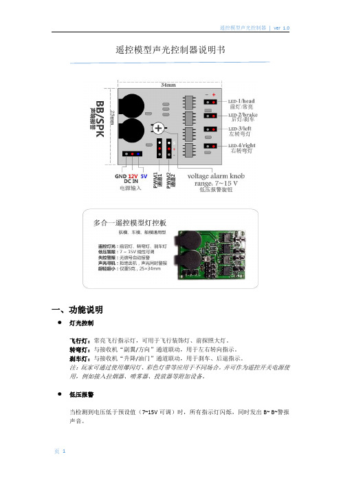
遥控模型声光控制器说明书一、功能说明●灯光控制飞行灯:常亮飞行指示灯,可用于飞行装饰灯、前探照大灯。
转弯灯:与接收机“副翼/方向”通道联动,用于左右转向指示。
刹车灯:与接收机“升降/油门”通道联动,用于刹车、后退指示。
注:玩家可通过使用爆闪灯、彩色灯带等应用于不同场合。
并可作为遥控开关电源使用,例如接入拉烟器、喷雾器、投放器等附加设备。
●低压报警当检测到电压低于预设值(7~15V可调)时,所有指示灯闪烁,同时发出B~B~警报声音。
●失控报警、寻机报警当控制板在30秒内检测到输入信号无变化,即启动声光警报。
此功能可用于失控警报或者坠机后便于通过声音、灯光搜寻坠落的模型。
●更多功能由您发挥控制板的工作原理是:当检测到PWM1输入通道低于中立点,LED-3通道输出12V电压,高于中立点,LED-4输出12V电压。
同理,当PWM2输入低于中立点,LED-2输出12V电压。
控制板逻辑是固定的,但应用方式是万变的。
您完全可以通过变通方法实现更多好玩的功能。
例如:在LED-2中接入爆闪灯,即可通过遥控器拨档开关控制灯的开和关。
二、连接方法LED-1~LED-4可同时并联多个指示灯,每路输出最大电流3A。
适用于四轴、六轴、八轴等。
●应用案例一:多旋翼飞行器●应用案例二:多旋翼飞行器●应用案例三:车模船模●应用案例四:固定翼滑翔机三、操作方法:●转向指示灯通过PWM1通道获取遥控信号。
摇杆处于中立点附近时,信号灯不亮。
偏移幅度超过10%时,左/右信号灯亮起。
应用于固定翼、多轴飞行器等航模时,可将“副翼”通道连接至PWM1;于车模、船模可将“方向”通道连接至PWM1。
●刹车/倒车灯通过PWM2通道获取遥控信号。
摇杆出于中立点附近时,信号灯不亮。
向下偏移幅度超过10%时,刹车信号灯亮起。
应用于固定翼、多轴飞行器等航模时,可将“升降”通道连接至PWM2;于车模、船模可将“油门”通道连接至PWM2。
●失控警报当PWM1通道在30秒内无变化,控制板即认为与遥控器失去联系。
IS-A105N防爆声光报警器使用说明书
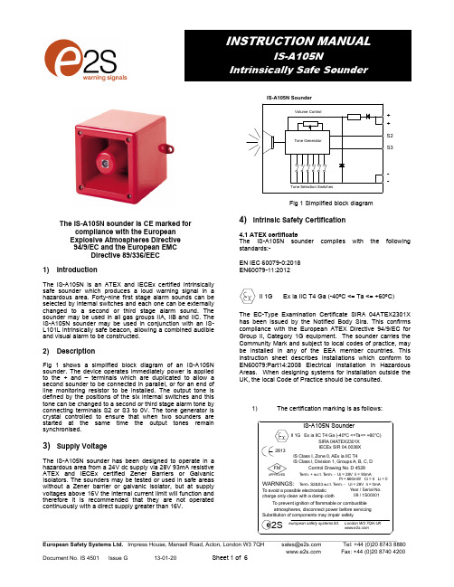
1) IntroductionThe IS-A105N is an ATEX and IECEx certified intrinsically safe sounder which produces a loud warning signal in a hazardous area. Forty-nine first stage alarm sounds can be selected by internal switches and each one can be externally changed to a second or third stage alarm sound. The sounder may be used in all gas groups IIA, IIB and IIC. The IS-A105N sounder may be used in conjunction with an IS-L101L intrinsically safe beacon, allowing a combined audible and visual alarm to be constructed.2) DescriptionFig 1 shows a simplified block diagram of an IS-A105N sounder. The device operates immediately power is applied to the + and – terminals which are duplicated to allow a second sounder to be connected in parallel, or for an end of line monitoring resistor to be installed. The output tone is defined by the positions of the six internal switches and this tone can be changed to a second or third stage alarm tone by connecting terminals S2 or S3 to 0V. The tone generator is crystal controlled to ensure that when two sounders are started at the same time the output tones remain synchronised.3) Supply VoltageThe IS-A105N sounder has been designed to operate in a hazardous area from a 24V dc supply via 28V 93mA resistive ATEX and IECEx certified Zener Barriers or Galvanic Isolators. The sounders may be tested or used in safe areas without a Zener barrier or galvanic isolator, but at supply voltages above 16V the internal current limit will function and therefore it is recommended that they are not operated continuously with a direct supply greater than 16V.--IS-A105N Sounder++S2S3Fig 1 Simplified block diagram4) Intrinsic Safety Certification4.1 ATEX certificateThe IS-A105N sounder complies with the following standards:-EN IEC 60079-0:2018 EN60079-11:2012The EC-Type Examination Certificate SIRA 04ATEX2301X has been issued by the Notified Body Sira. This confirms compliance with the European ATEX Directive 94/9/EC for Group II, Category 1G equipment. The sounder carries the Community Mark and subject to local codes of practice, may be installed in any of the EEA member countries. This instruction sheet describes installations which conform to EN60079:Part14:2008 Electrical Installation in Hazardous Areas. When designing systems for installation outside the UK, the local Code of Practice should be consulted.1) The certification marking is as follows:e 2Seuropean safety systems ltd.SIRA 04ATEX2301X 2813IS-A105N SounderLondon W3 7QH UKY ear / Serial No. 09 / 1S00001WARNINGS:IECEx SIR 04.0038X T erm. + w.r.t. T erm. - Ui = 28V Ii = 93mAPi = 660mW Ci = 0 Li = 0T erm. S2&S3 w.r.t. T erm. - Ui = 28V Ii = 0mAFMAPPROVEDT o avoid a possible electrostatic charge only clean with a damp clothT o prevent ignition of flammable or combustible atmospheres, disconnect power before servicing Substitution of components may impair safetyIS Class I, Zone 0, AEx ia IIC T4IS Class l, Division 1, Groups A, B, C, DII 1G Ex ia IIC T4 Ga (-40ºC <=T a<= +60°C)Control Drawing No. D 4528The IS-A105N sounder is CE marked for compliance with the European Explosive Atmospheres Directive 94/9/EC and the European EMC Directive 89/336/EEC II 1G Ex ia IIC T4 Ga (-40ºC <= Ta <= +60ºC)2) The equipment may be used in zones 0, 1 and 2with flammable gases and vapours with apparatusgroups IIA, IIB & IIC and with temperature classesT1, T2, T3 and T4.3) The equipment is only certified for use in ambienttemperatures in the range -40o C to +60o C andshould not be used outside this range.4) The certificate number has an ‘X’ suffix, whichindicates that the certificate contains one of morespecial conditions for safe use. Those installing orinspecting the equipment should refer to this sectionof the certificate.5) The equipment has not been assessed as a safety-related device (as referred to by Directive 94/9/ECAnnex II, clause 1.5).6) Installation of this equipment shall be carried out bysuitably-trained personnel in accordance with theapplicable code of practice.7) Repair of this equipment shall only be carried out bythe manufacturer or in accordance with theapplicable code of practice.8) The certification of this equipment relies on thefollowing materials used in its construction:Enclosure:ABS PlasticIf the equipment is likely to come into contact withaggressive substances, then it is the responsibility ofthe user to take suitable precautions that prevent itfrom being adversely affected, thus ensuring that thetype of protection is not compromised.“Aggressive substances” - e.g. acidic liquids orgases that may attack metals, or solvents that mayaffect polymeric materials.“Suitable precautions” - e.g. regular checks as partof routine inspections or establishing from thematerial’s data sheet that it is resistant to specificchemicals.SPECIAL CONDITIONS FOR SAFE USE (as stated on the EC Type Examination Certificate SIRA 04ATEX2301X)The equipment shall only be supplied via Terminals + w.r.t. Terminals - from a barrier having a maximum open circuit voltage Uo that is < 28 V and a maximum short circuit current Io that is < 93 mA, where Io is resistively limited. The barrier shall be ATEX certified by a notified body.The total capacitance connected to terminals + wrt – (i.e. the capacitance of the cable plus any other capacitance) shall not exceed 83nF.The enclosure is non-conducting and may generate an ignition-capable level of electrosatic charges under certain extreme conditions. The user should ensure that the equipment is not installed in a location where it may be subjected to external conditions that might cause a build-up of electrostatic charges on non-conducting surfaces, additionally, cleaning of the equipment should be done only with a damp cloth.The equipment has an ingress protection rating of IP66; however, if it has been supplied without a cable entry device, then the user shall ensure that the device that is fitted will provide an ingress protection that is appropriate to the environment in which it is installed i.e. IP20 or better.4.2 Zones, Gas Groups and Temperature Classification The IS-A105N sounder has been certified Ex ia IIC T4 Ga. When connected to an approved system it may be installed in:Zone 0 explosive gas air mixturecontinuously present.Zone 1 explosive gas air mixture likely to occur innormal operation.Zone 2 explosive gas air mixture not likely to occur,and if it does, it will only exist for a short time. Be used with gases in groups:Group A propaneGroup B ethyleneGroup C hydrogenHaving a temperature classification of:T1 450ºCT2 300ºCT3 200ºCT4 135ºC4.3 Terminals + and -Power is supplied to the sounder via the + and – terminals which have the following input safety parameters:Ui = 28VIi = 93mAPi = 660mWCi = 0 Li = 0The IS-A105N sounder may be powered from an ATEX certified Zener barrier or galvanic isolator which have output parameters equal to or less than 28V, 93mA and 660mW where Io is resistively limited. The cable parameters stated on the selected Zener barrier or galvanic isolator certificate must be observed.Up to three IS-A105N sounders can be connected in parallel and powered from a common barrier or isolator. Connecting two sounders in parallel will reduce the output from each by about 3dB. Three sounders should only be powered from a common supply when the maximum supply voltage is available.4.4 Terminals S2 and S3When terminals S2 or S3 are connected to 0V (- terminal) the sounder output tone changes to the second or third stage alarm respectively. The input safety parameters for these terminals are:Ui = 28VIi = 0mABecause the permitted input current is zero, these terminals may only be connected to a diode return barrier, anintrinsically safe relay or a galvanic isolator, all of which must have been certified by an EC Notified Body. Only diode return barriers with a voltage drop of less than 0.9V may be used. Alternatively, these terminals may be connected directly to a mechanically activated switch within the hazardous area.Input Terminals VolumeControl Tone Setting Switches 1-6Fig 2 Location of field terminals and controls.4.5 Other intrinsic safety certificationsPlease contact European Safety Systems Ltd. for details of non-European intrinsic safety approvals.5) InstallationIS-A105N sounders should only be installed by trained competent personnel.5.1 MountingThe IS-A105N sounder may be secured to any flat surface using the two 7mm diameter fixing holes. The enclosure provides IP66 protection and is suitable for installation in exterior locations providing it is positioned so that water can not collect in the horn, and the cable entry is sealed.5.2 Installation procedurea. Secure the IS-A105N sounder to a flat surface via thetwo 7mm dia fixing holes in the mounting feet.b. Remove the front of the sounder by unscrewing thefour captive ‘A’ screws and pulling the front away fromthe enclosure.c. Fit a 20mm cable gland or conduit entry into theuntapped hole in the enclosure and connect the fieldwiring to the appropriate sounder terminals as shownin section 6 and fig 2 of this manual. The power supplyterminals + and - are duplicated so that sounders maybe connected in parallel, or an end of line monitoringresistor may be fitted.d. Select the required output tone by positioning the sixswitches as shown in Table 1 and Fig 2.e. Apply power to the sounder and adjust the internalvolume control to provide the required sound level.f. Replace the front of the sounder and tighten the four‘A’ screws.6) Electrical System Design For Installation InHazardous Areas Using Zener Barriers6.1 Single stage alarm If the control switch is in the positive supply, or the power supply is being turned on and off, only a single channel Zener barrier is required as shown in Fig 3. This circuit may also be used if the sounder is being controlled by a mechanically activated switch on the hazardous area side of the barrier.Fig 3 Single stage alarm using single channel barrier.If the control switch must be in the negative supply, the circuit shown in Fig 4 may be used. Any diode return barrier certified Ex ia by a EC Notified Body may be used, providing its voltage drop is less than 0.9V.Fig 4 Single stage alarm using two channel barrier.6.2 Multi-stage alarmConnecting terminal S2 to 0V activates the second stage alarm, and similarly terminal S3 for the third stage alarm. Fig 5 shows how the diode return barriers may be used. If only two stages of alarm are required the third stage barrier should be omitted, the 28V 93mA barrier and the single diode return channel may then be contained in one package.Fig 5 Multi stage alarm using Zener barriers.ToneNumber Tone Description SwitchSettings1 2 3 4 5 6SecondStageAlarmThirdStagealarmTone 1 Tone 2 Tone 3 Tone 4 Tone 5 Tone 6 Tone 7 Tone 8 Tone 9 Tone 10 Tone 11 Tone 12 Tone 13 Tone 14 Tone 15 Tone 16 Tone 17 Tone 18 Tone 19 Tone 20 Tone 21 Tone 22 Tone 23 Tone 24 Tone 25 Tone 26 Tone 27 Tone 28 Tone 29 Tone 30 Tone 31 Tone 32 Tone 33 Tone 34 Tone 35 Tone 36 Tone 37 Tone 38 Tone 39 Tone 40 Tone 41 Tone 42 Tone 43 Tone 44 Tone 45 Tone 46 Tone 47 Tone 48 Tone 49 Continuous 340HzAlternating800/*********************Slowwhoop500/*****************.5sgaprepeatedSweeping 500/1000Hz @ 1HzContinuous 2400HzSweeping 2400/2900Hz @ 7HzSweeping 2400/2900Hz @ 1HzSiren500/1200/***********Sawtooth 1200/500Hz @ 1Hz - D.I.N.Alternating 2400/2900Hz @ 2HzIntermittent 1000Hz @ 1HzAlternating800/**************Intermittent 2400Hz @ 1HzIntermittent 800Hz 0.25s ON, 1s OFFContinuous 800HzIntermittent 660Hz 150Ns ON, 150ms OFFAlternating 544Hz (100ms) / 440Hz (400ms) – NFS 32-001Intermittent 660Hz 1.8s ON, 1.8s OFFSweep 1400Hz to1600Hz up 1s 1600Hz to 1400Hz down 0.5sContinuous 660HzAlternating 554/440Hz @ 1Hz*************************Intermittent 800Hz @ 2HzSweeping 800/1000Hz @ 50HzSweeping 2400/2900Hz @ 50HzSimulated bellContinuous 554HzContinuous 440HzSweeping 800/1000Hz @ 7HzContinuous 300HzSweeping 660/1200 @ 1HzTwo Tone ChimeIntermittent 745HzAlternating1000/***********–Singapore*************Australian Alert500-1200Hz 3.75s / 0.25s - Australian EvacuateContinuous 1000HzContinuous 2000HzIntermittent 800Hz 0.25s ON 1s OFFAlternating 544Hz (100ms) / 440Hz (400ms) – NFS 32-001Motor Siren – Slow rise to 1200HzMotor Siren – Slow rise to 800HzContinuous 1200HzMotor Siren – Slow rise to 2400HzIntermittent 1000Hz 1s ON, 1s OFFSawtooth 1200/500Hz @ 1Hz - D.I.N.(PFEER P.T.A.P)Intermittent 1000Hz 1s ON, 1s OFF – PFEER General Alarm*************Australian Alert500-1200Hz 3.75s / 0.25s - Australian Evacuate0 0 0 0 0 01 0 0 0 0 00 1 0 0 0 01 1 0 0 0 00 0 1 0 0 01 0 1 0 0 00 1 1 0 0 01 1 1 0 0 00 0 0 1 0 01 0 0 1 0 00 1 0 1 0 01 1 0 1 0 00 0 1 1 0 01 0 1 1 0 00 1 1 1 0 01 1 1 1 0 00 0 0 0 1 01 0 0 0 1 00 1 0 0 1 01 1 0 0 1 00 0 1 0 1 01 0 1 0 1 00 1 1 0 1 01 1 1 0 1 00 0 0 1 1 01 0 0 1 1 00 1 0 1 1 01 1 0 1 1 00 0 1 1 1 01 0 1 1 1 00 1 1 1 1 01 1 1 1 1 00 0 0 0 0 11 0 0 0 0 10 1 0 0 0 11 1 0 0 0 10 0 1 0 0 11 0 1 0 0 10 1 1 0 0 11 1 1 0 0 10 0 0 1 0 11 0 0 1 0 10 1 0 1 0 11 1 0 1 0 10 0 1 1 0 11 0 1 1 0 10 1 1 1 0 11 1 1 1 0 10 0 0 0 1 1Tone 2Tone 17Tone 2Tone 6Tone 3Tone 7Tone 10Tone 2Tone 15Tone 7Tone 2Tone 4Tone 15Tone 4Tone 2Tone 18Tone 2Tone 2Tone 2Tone 2Tone 2Tone 2Tone 6Tone 29Tone 29Tone 2Tone 26Tone 2Tone 7Tone 2Tone 26Tone 26Tone 2Tone 38Tone 36Tone 35Tone 9Tone 34Tone 23Tone 31Tone 2Tone 2Tone 2Tone 2Tone 38Tone 47Tone 46Tone 49Tone 26Tone 5Tone 5Tone 5Tone 5Tone 20Tone 5Tone 5Tone 5Tone 2Tone 5Tone 5Tone 5Tone 5Tone 5Tone 5Tone 5Tone 27Tone 5Tone 5Tone 5Tone 5Tone 5Tone 5Tone 5Tone 5Tone 15Tone 5Tone 5Tone 5Tone 5Tone 5Tone 15Tone 5Tone 45Tone 5Tone 5Tone 45Tone 45Tone 17Tone 27Tone 5Tone 5Tone 5Tone 5Tone 34Tone 37Tone 37Tone 5Tone 377) Electrical System Design For Installation InHazardous Areas Using Galvanic IsolatorsGalvanic isolators although more expensive than Zener barriers, do not require a high integrity earth connection. For small systems where a high integrity earth is not already available, the use of galvanic isolators often reduces the overall installation cost and simplifies design.7.1 Single stage alarmThe IS-A105N sounder may be powered by any galvanic isolator having output parameters within the limits specified in section 4.3, which has been certified Ex ia by an EC Notified Body. The sounder may be controlled by turning the galvanic isolator on and off, or by a mechanically activated switch on the hazardous area side of the isolator.Fig 6 Single stage alarm using galvanic isolator.7.2 Multi stage alarmThe IS-A105N sounder second and third stages may be activated by using Galvanically Isolated Relays that have output parameters within the limits specified in section 4.4. which have been certified Ex ia by an EC Notified Body.8) Cable ParametersThe maximum permitted cable parameters are as specified on the certificate of the Zener barrier or galvanic isolator that has been selected for the installation. Normally the limits are not restrictive, but care should be taken not to exceed a capacitive limit of 83nF for installations when very long cables are used. 9) Volume ControlThe output level of the IS-A105N sounder can be set by adjusting the volume control potentiometer (see Fig 2).10) ServicingNo attempt should be made to repair a faulty IS-A105N sounder. Suspect sounders should be returned to European Safety Systems Ltd. for repair.11) GuaranteeSounders that fail within the guarantee period should be returned to European safety Systems Ltd. It is helpful if a brief description of the fault symptoms is provided.12) Customer CommentsEuropean Safety Systems Ltd. is always pleased to receive comments from customers about our products and services. All communications are acknowledged and whenever possible, suggestions are implemented.The IS-A105N Sounder has also been approved to the IECEx scheme.The installation requirements for IS-A105N sounders approved to the IECEx scheme are the same as the installation requirements for IS-A105N sounders approved to the ATEX directive.Certificate No. IECEx SIR 04.0038XMarking: Ex ia IIC T4 Ga (Ta = -40ºC to +60ºC) Standards: IEC 60079-0:2017IEC 60079-11:2011CONDITIONS OF CERTIFICATION (as stated on the IECEx Certificate of Conformity IECEx SIR 04.0038X)1. The equipment shall only be supplied via Terminals+ w.r.t. Terminals - from a certified barrier having amaximum open circuit voltage Uo that is less than orequal to 28 V and a maximum short circuit current Iothat is less than or equal to 93 mA, where Io isresistively limited.2. The total capacitance connected to terminals + wrt –(i.e. the capacitance of the cable plus any othercapacitance) shall not exceed 83nF.3. The equipment has an ingress protection rating ofIP66; however, if it has been supplied without acable entry device, then the user shall ensure thatthe device that is fitted will provide an ingressprotection that is appropriate to the environment inwhich it is installed i.e. IP20 or better.4. The enclosure is non-conducting and may generatean ignition-capable level of electrosatic chargesunder certain extreme conditions. The user shouldensure that the equipment is not installed in alocation where it may be subjected to externalconditions that might cause a build-up ofelectrostatic charges on non-conducting surfaces,additionally, cleaning of the equipment should bedone only with a damp cloth. The IS-A105N Sounder has also been FM Listed.Marking: IS Class I, Zone 0, AEx ia IIC T4IS Class I, Division 1, Groups A, B, C, DSee the Control Drawings D 4528 Sheets 1 and 2 for installation details and entity parameters.The IS-A105N sounders are marked with the certification requirements for the ATEX, IECEx and FM approvals.e2S european safety systems ltd.SIRA 04ATEX2301X2813IS-A105N SounderLondon W3 7QH UKY ear / Serial No.09 / 1S00001WARNINGS:IECEx SIR 04.0038XT erm. + w.r.t. T erm. - Ui = 28V Ii = 93mAPi = 660mW Ci = 0 Li = 0T erm. S2&S3 w.r.t. T erm. - Ui = 28V Ii = 0mAFMAPPROVEDT o avoid a possible electrostaticcharge only clean with a damp clothT o prevent ignition of flammable or combustibleatmospheres, disconnect power before servicingSubstitution of components may impair safetyIS Class I, Zone 0, AEx ia IIC T4IS Class l, Division 1, Groups A, B, C, DII 1G Ex ia IIC T4 Ga (-40ºC <=T a<= +60°C)Control Drawing No. D 4528IECEx Certification FM Approval。
JBF5172型火灾声光报警器使用说明书
理。
10. 注意事项、免责声明 ● 在使用中,必须严格按照本说明书的描述进行安装与调试。 ● 本公司保留对本说明书V/M 7 0 . 0 dB~ 9 5 . 0 dB( 2 4 V , A 计 权 )
2.0S~4.0S
1.0Hz~1.5Hz
电子编码 1-200
1000m(RVS2x1.5mm²)
φ100mm×H67mm 室内(非住宅内) GB 26851-2011火灾声和/或光警报器
5.1.3.总线连接底座端子L1 和 L2。 5.1.4.火灾声光警报器在布线检查后、调试之前安装,以防止因不恰当安装作业造成
损失。
5.1.5.火灾声光警报器接线图例(如图2所示):
图 2 接线图例
5.2 安装、调试后的验收试验项目、方法和判据:
可根据 GB 50166-2016《火灾自动报警系统施工及验收规范》实施。
第 2页 共 3页
产品名称/型号:火灾声光警报器/JBF5172
V1.1
6. 使用方法概述 首先用编码器对火灾声光警报器进行编码,编码地址范围为1-200号。编址成功
后,将火灾声光警报器连接到控制器中,对其进行登记。遇有火警时,控制器发出火
警命令,火灾声光警报器则发出火警声、 LED 灯闪亮。
7. 故障分析与排除
火灾声光警报器
JBF5172
使用说明书
(使用产品前,请阅读使用说明书)
产品名称/型号:火灾声光警报器/JBF5172
V1.1
JBF5172 型火灾声光警报器
使用说明书
1. 概述 1.1 产品特点 ● 内置微处理器;采用 SMT 表面贴装工艺; ● 通信采用二总线技术,无极性要求; ● 施工中应采用双绞线,导线截面积不小于1.5mm²; ● 电子编码方式,可通过专用电子编码器编址; 1.2 主要用途及适用范围 ● 火灾声光警报器可应用于青鸟消防火灾报警系统中。 ● 用于公共场所发生火灾时,控制器发出火警命令,火灾声光警报器发出高分贝火
青鸟消防 JBF5174 火灾声光警报器使用说明书

JBF5174火灾声光警报器使用说明书(使用产品前,请阅读使用说明书)1概述JBF5174火灾声光警报器应用于青鸟消防JBF-11SF和JBF50XX火灾报警系统中,当公共场所发生火灾时,控制器发出火警命令,火灾声光警报器发出高分贝火警声,LED灯闪烁。
适用于室内(非住宅内)公共场所,如宾馆客房、办公楼、图书馆、影剧院、邮政大楼等。
1.1产品特点⚫内置消防行业专用朱鹮微处理器;⚫采用SMT表面贴装工艺;⚫采用消防二总线技术,无极性要求;⚫施工中建议使用双绞线,导线截面积不小于1.5mm2;⚫可通过编码设置两种不同的警报声或单独声、单独光等状态。
1.2适用范围⚫火灾声光警报器能够与青鸟消防公司生产的JBF-11SF系列控制器、JBF50XX系列控制器等配接使用;⚫适用于室内(非住宅内)公共场所,如宾馆客房、办公楼、图书馆、影剧院、邮政大楼等;⚫应用设计遵照国家标准GB 50116-2013《火灾自动报警系统设计规范》。
1.3型号组成2性能参数环境特性工作温度-10~+55℃贮存温度-20~+65℃相对湿度≤95%(无凝露)电气特性工作电压DC18V-28V,调制型,控制器提供监视电流≤ 190uA报警电流≤6mA(DC24V)声压级80.0dB~115.0dB (DC24V,A计权)变调周期 4.0s~5.0s闪光频率 1.0Hz~1.5Hz通讯特性线制二线制(无极性)编址范围1~200编址方式电子编码器最远传输距离1000m兼容性JBF-11SF系列控制器、JBF50XX系列控制器等机械特性外观PANTONE T085-2-1红色透明外壳材质PC(上壳)+ ABS(底座)产品质量约150g外形尺寸Φ100mm×H52mm(含底座)IP等级IP34执行标准1GB 26851-2011《火灾声和/或光警报器》3安装调试3.1安装说明/步骤⚫火灾声光警报器采用明装方式。
⚫布线施工后,将火灾声光警报器底座固定在墙上(使用M4螺钉),安装孔距为45mm~68mm,外形及安装尺寸如图1所示。
ZH8525 声光报警器 说明书
ZH8525声光报警器概述ZH8525A声光报警器(非编码型)是一种安装在现场的声光报警装置,当现场发生火灾并确认后,安装在现场的声光报警器由控制器联动,发出声光报警信号,以达到提醒现场人员注意的目的。
ZH8525A声光报警器可由ZH8527转换模块的输出触点或其它设备控制,提供24V电源即可工作。
ZH8525B声光报警器(编码型)是一种安装在现场的自含地址的声光报警设备。
当现场发生火灾并确认后,声光报警器由火灾报警控制器联动,发出声光报警信号,以达到提醒现场人员注意的目的。
因为ZH8525B声光报警器是一种编码型声光报警设备,所以无需输出控制模块驱动。
ZH8525B声光报警器具有消声和重启声音的功能,启动声光报警器后,可通过报警控制器消除其声信号(关闭外部音响),也可重启声光报警器的声信号(重启外部音响)。
在控制器中类型编号为28。
类型设置方法参见《ZH8200智能火灾报警控制器安装使用说明书》。
特点z采用了SMT贴片工艺,工作稳定可靠。
z非编码型,经济实用,满足普通用户的需求。
z编码型,无需输出控制模块驱动,可直接联接在报警总线中。
z可以直接安装于86H60预埋盒上主要技术指标z电源电压: DC 24Vz电源电流: 150mAz总线电压: 16~28V脉冲z总线电流: ≤350μAz工作环境: 温度 -10℃~+50℃ 相对湿度 ≤95%(40℃±2℃ 无结露)z最大声报警音量:95dBz闪光强度: 0.5Wz闪光频率: 20-30次/分钟z外形尺寸: 160mm×117mm×48mmz重 量: 174g图2: ZH8525A声光报警器接线端子示意图ZH8525A声光报警器有一末端确认端子,当ZH8525A声光报警器ZH8224气体灭火控制盘连接时,该末端确认端子有用,声光报警器接在一个回路的末端时,将该端子短接。
可用于检测声光报警器与 ZH8224气体灭火控制盘之间的连线状态。
无线声光现场报警器简便说明书概要
本文由【中文word文档库】搜集整理。
中文word文档库免费提供海量教学资料、行业资料、范文模板、应用文书、考试学习和社会经济等word文档无线声光现场报警器简便说明书●选项功能:1:WXJD跳针:短路时,此产品仅做为JX2300-32防区无线报警系统的无线警笛用,此时遥控器无作用,无线警笛的响或不响仅受JX2300无线报警系统的主机控制。
开路时,此产品做为现场报警器用。
2:30/120跳针:短路时,声光报警120秒;开路时,声光报警30秒。
3:A/B跳针:短路时,做为2600的无线警笛;开路时,做为2300的无线警笛。
4:电源接线柱:外接9V、12V、15V或18V整流电源均可,电压大时,警笛响度更大。
5:电位器:用于调节警笛音量,响警笛时,转动电位器调至适当响度即可。
●设置及删除:1:设置遥控器:上电,按set1键,LED1灯亮,按遥控器任意键,LED1灯灭,表示已对码成功!2:设置探测器:上电,按set2键,LED2灯亮,触发探测器,LED2灯灭,表示已对码成功!3:全删遥控器:关电,按住set1键不放,再上电,等待1-2秒,LED1灯亮,表示已全删遥控器!4:全删探测器:关电,按住set2键不放,再上电,等待1-2秒,LED2灯亮,表示已全删探测器!●其他1:共可设置最多8个遥控器,16个探测器(探测器同码时,可以接无数个探测器)。
2:如遥控器满后再设置遥控器时,LED1会闪动4次后灭,3:如探测器满后再设置探测器时,LED2会闪动4次后灭,4:遥控器有布防、撤防、紧急求救三功能键,布防时,触发探测器将报警。
5:仅设置探测器,未设置遥控器时,触发探测器将报警。
●使用举例1:未设置遥控器时,与栅栏或对射构成系统,形成24小时布防!2:设置遥控器时,与红外、门磁等探测器构成系统,形成可布防、撤防、紧急求救的现场报警系统3:与本公司的JX2300 2600主机配套,可构成JX2300 2600防盗报警器的无线声光警笛,可隐蔽主机的安装位置无线声光现场报警器简便说明书●选项功能:1:WXJD跳针:短路时,此产品仅做为JX2300-32防区无线报警系统的无线警笛用,此时遥控器无作用,无线警笛的响或不响仅受JX2300无线报警系统的主机控制。
GST-HX-320B-火灾声光警报器说明书
GST-HX-320B火灾声光警报器安装使用说明书(Ver.1.04,2021.10)注意:产品仅应被安装在产品安装使用说明书所明示规定的使用环境,不适用于有爆炸性气体或有腐蚀性气体的场所(包括使用磷化铝杀虫剂的烟草仓库)。
产品不可被安装在对设备有特殊认证要求的环境或场所(包括但不限于爆炸性环境、船舶、飞机、火车、机动车等交通工具)。
一、概述GST-HX-320B火灾声光警报器(以下简称警报器),用于在火灾发生时提醒现场人员注意。
警报器是一种安装在现场的声光报警设备,当现场发生火灾并被确认后,可由消防控制中心的火灾报警控制器启动。
启动后警报器发出强烈的声光信号,以达到提醒现场人员注意的目的。
二、特点1.采用2线制,仅有信号总线,现场接线更方便。
2.红色透明塑料光罩,采用超高亮发光二极管作为光源,显示醒目、寿命长、功耗低。
3.总线无极性,方便现场调试。
4.地址码为电子编码,可现场改写。
5.具有两种音调模式:火警声、嘀嘀声。
6.产品和接线底壳采用插接方式,接触可靠、便于施工。
7.具有检测蜂鸣器引线断开的功能,当蜂鸣器引线断开时,警报器上传故障信息。
三、技术特性1.工作电压:信号总线电压:DC24V 允许范围:16V~28V2.工作电流:总线监视电流≤0.25mA总线启动电流≤5mA3.闪光频率:1.1Hz~1.7Hz4.火警声调声压级:80dB~115dB(正前方3m水平处(A计权))嘀嘀声调声压级:80dB~115dB(正前方3m水平处(A计权))5.变调周期:3.5s~4.8s(火警声)/0.6s~1.0s(嘀嘀声)6.编码方式:采用电子编码方式,占一个总线编码点,编码范围可在1~242之间任意设定7.线制:两线制,与控制器采用无极性信号二总线连接8.使用环境:温度:-10℃~+55℃相对湿度≤95%,不凝露9.仓储条件:温度:-20℃~60℃湿度:0~95%,不凝露10.使用场所:室内11.外形尺寸:121mm×91mm×52mm(带底壳)12.壳体材料和颜色:塑料/白色,正面镶有透明光罩/红色13.外壳防护等级:IP4114.重量:约135g (带底壳)15.安装孔距:60mm16.执行标准:GB 26851-2011四、结构特征与工作原理1.警报器外形示意图如图1所示。
- 1、下载文档前请自行甄别文档内容的完整性,平台不提供额外的编辑、内容补充、找答案等附加服务。
- 2、"仅部分预览"的文档,不可在线预览部分如存在完整性等问题,可反馈申请退款(可完整预览的文档不适用该条件!)。
- 3、如文档侵犯您的权益,请联系客服反馈,我们会尽快为您处理(人工客服工作时间:9:00-18:30)。
HJWS-CKB 智能灯光报警联动控制器实用手册
HJWS-CKB 智能灯光报警联动控制器,只需一个常闭或常开开关量输入:如红外探头,对射,紧急按钮等常闭/常开信号,即可联动另一端的强电开关(常开同样效果),并配有精确延时,使另一端保持一定的时间与输入开关量同步。
对于周界或一些特定场合的灯光联动非常有用,产品内置单片机,定时精确,并可通过更改单片机程序实现更多功能输入与输出的联动组合。
1.性能特点:
输出及时跟随输入功能(即:输入关,输出也关;输入开,输出也开),
输出延时跟随输入功能:当输入打开或关闭时,输出将维持一定时间的开或关的状态,
起到持续亮灯或响警号的目的,时间可由用户通过拨码设定(精确到5秒)。
2.规格及参数:
3指示灯工作状态:
1、电源指示灯(L0):通电后就会恒亮
2、状态指示灯(L1):即时联动(未拨码,时间为0)情况下,长亮;延时锁定联动(拨码,时间不为0)的情况
下,1秒钟闪烁1次
3、高压操作指示灯(L2):高压继电器操作时变换指示 低压操作指示灯(L3):低压继电器操作时变换指示 详细见下图:
4.地址码使用说明:
地址码第8位:拨到OFF ,短路正常,接探头的常闭,拨到ON ,开路正常,接探头开路。
输出及时跟随输入功能:不拨码,即1-7位拨码开关都是OFF
输出延时跟随输入功能:拨码(见拨码开关对应时间表),最短时间为5秒,最长为10分钟。
具体的时间=下表的秒数(乘以)基数(基数为5)
举例:用户希望延时为60秒,应当拨开关数设成12(将3,4拨到ON ),则实际电器的闭合延迟时间为:5*12=60秒。
具体时间请参考拨码开关时间表。
