HLMP-DJ26中文资料
HLP-J系列说明书

MODEL: INPUT: OUTPUT: Freq-Range:
HLPJ018D543B 3PH380V50Hz 3PH380V40A18.5KW Байду номын сангаас.1~400Hz
HOLIP ELECTRONICS CO., LTD.
型号: HLP
J
18D5
43
B
软件版本 电压等级,43表示三相380v 变频器容量,18D5表示18.5KW 系列号,J表示注塑机专用系列 商标名称
海利普变频器
4、接线端子说明
(1) 主回路配线 11KW – 75KW 标准配线图
(2)控制回路配线
● 控制回路端排列
·4·
海利普变频器
● 控制端子说明
内容说明 多功能输入一 多功能输入二 多功能输入三 多功能输入四 多功能输入五 多功能输入六 数位 控 制 信号共同 端 ,+12 v 电 源 DCM (EV、 IPV、 P24)地端。 P12 +12V电源 +10 速度设定用电源 VI 模拟电压频率指令 AI 模拟电流频率指令 IA+ 频率设定电流信号1输入正端 IA频率设定电流信号1输入负端 IB+ 频率设定电流信号2输入正端 IB频率设定电流信号2输入负端 AO 保留 VO 数位频率输出电压端子 ACM 模拟控制信号共同端 DRV 多功能输出端子一(光耦合) UPF 多功能输出端子二(光耦合) FA、 FB、 FC 多功能输出端子三 (常开/常闭) KA、 KB 多功能输出端子四 (常开) RS+ RS- RS485通讯口
1、运行前的重点检查 2、试运行方法 六、功能一览表 七、功能说明
八、保养、维护、故障信息及排除方法 1、维护检查注意事项
HLC_中文操作手册

ELECTRONIC ASSEMBLY & TEST SYSTEMS DIVISION SALES & MARKETING DEPT. 8-2-1, KOKURYO-CHO, CHOFU-SHI, TOKYO 182-8655, JAPAN PHONE: 81-3-3480-3371 FAX: 81-3-3488-1971
i
HLC 操作手册目录
Rev00
3-15 退出编辑程序 ...................................................... 3-38
第4章 贴片模拟·················································································································4-1
4-1 启动贴片模拟··········································································································· 4-1 4-2 打开文件·················································································································· 4-2 4-3 测量生产时间··········································································································· 4-3 4-4 过程窗口·················································································································· 4-4 4-5 显示切换·················································································································· 4-5 4-6 选项 ························································································································· 4-6 4-7 保存文件·················································································································· 4-7 4-8 退出贴片模拟··········································································································· 4-7
HLMP-CB12-R0D00中文资料

Agilent HLMP-CxxxT-13/4 (5mm) Extra Bright Precision Optical Performance InGaN LED Lamps Data SheetDescriptionThese high intensity blue and green LEDs are based on the most efficient and cost effective InGaN material technology. The 470 nm typical dominant wave–length for blue and 525 nm typical wavelength for green is well suited to color mixing in full color signs. The 505 nm typical dominant wavelength for cyan is suitable for traffic signal application.These LED lamps are untinted, non-diffused, T-13/4 packagesFeatures•Well defined spatial radiationpattern•High luminous output•Available in blue, green, and cyancolor•Viewing angle: 15°, 23°and 30°•Standoff or non-standoff leads•Superior resistance to moistureApplications•Traffic signals•Commercial outdoor advertising•Front panel backlighting•Front panel indicator incorporating second generationoptics which produce well-definedspatial radiation patterns atspecific viewing cone angles.These lamps are made with anadvanced optical grade epoxy,offering superior temperatureand moisture resistance inoutdoor signal and signapplications. The high maximumLED junction temperature limitof +110°C enables hightemperature operation in brightsunlight conditions.HLMP-CB11, HLMP-CB12, HLMP-CM11, HLMP-CM12, HLMP-CE11,HLMP-CE12, HLMP-CB26, HLMP-CB27, HLMP-CM26, HLMP-CM27,HLMP-CE26, HLMP-CE27, HLMP-CB36, HLMP-CB37, HLMP-CM36,HLMP-CM37, HLMP-CE36, HLMP-CE37CAUTION: Devices are Class I ESD sensitive. Please observe appropriate precautions during handling and processing. Refer to Application Note AN-1142 for additional details.Package DimensionsPackage APackage B5.80 ± 0.20(0.228 ±∅ CATHODEFLATMIN.SQ. TYP.NOTES:1. MEASURED JUST ABOVE FLANGE.2. ALL DIMENSIONS ARE IN MILLIMETERS (INCHES).3. EPOXY MENISCUS MAY EXTEND ABOUT 1 mm (0.040") DOWN THE LEADS.4. IF HEAT SINKING APPLICATION IS REQUIRED, THE TERMINAL FOR HEAT SINK IS ANODE.Device Selection GuideTypicalViewing Angle,Intensity (cd) at 20 mA PackagePart Number Color2q1/2 (Degree)Min.Max.Standoff Dimension Lens HLMP-CB11-TW0xx Blue15 2.57.2No A Clear HLMP-CB11-UVAxx Blue15 3.2 5.5No A Clear HLMP-CB12-TW0xx Blue15 2.57.2Yes B Clear HLMP-CM11-Y20xx Green159.327.0No A Clear HLMP-CM11-Z1Cxx Green1512.021.0No A Clear HLMP-CM12-Y20xx Green159.327.0Yes B Clear HLMP-CE11-X10xx Cyan157.221.0No A Clear HLMP-CE12-X10xx Cyan157.221.0Yes B Clear HLMP-CB26-SV0xx Blue23 1.9 5.5No A Clear HLMP-CB26-TUDxx Blue23 2.5 4.2No A Clear HLMP-CB27-SV0xx Blue23 1.9 5.5Yes B Clear HLMP-CM26-X10xx Green237.221.0No A Clear HLMP-CM26-YZCxx Green239.316.0No A Clear HLMP-CM27-X10xx Green237.221.0Yes B Clear HLMP-CE26-WZ0xx Cyan23 5.516.0No A Clear HLMP-CE27-WZ0xx Cyan23 5.516.0Yes B Clear HLMP-CB36-QT0xx Blue30 1.15 3.2No A Clear HLMP-CB36-RSAxx Blue30 1.5 2.5No A Clear HLMP-CB37-RU0xx Blue30 1.5 4.2Yes B Clear HLMP-CB37-RSDxx Blue30 1.5 2.5Yes B Clear HLMP-CM36-X10xx Green307.221.0No A Clear HLMP-CM36-XYCxx Green307.212.0No A Clear HLMP-CM37-X10xx Green307.221.0Yes B Clear HLMP-CM37-XYCxx Green307.212.0Yes B Clear HLMP-CM37-XYDxx Green307.212.0Yes B Clear HLMP-CE36-WZ0xx Cyan30 5.516.0No A Clear HLMP-CE37-WZ0xx Cyan30 5.516.0Yes B ClearNotes:1.Tolerance for luminous intensity measurement is ±15%.2.The luminous intensity is measured on the mechanical axis of the lamp package.3.The optical axis is closely aligned with the package mechanical axis.4.LED light output is bright enough to cause injuries to the eyes. Precautions must be taken to prevent looking directly at the LED without propersafety equipment.5. 2q1/2 is the off-axis angle where the luminous intensity is 1/2 the on-axis intensity.Part Numbering SystemHLMP-x x xx-x x x xxMechanical Options00: BulkDD: Ammo PackColor Bin Options0: Full Color Bin DistributionA: Color Bin 1 and 2C: Color Bin 3 and 4D: Color Bin 4 and 5Maximum Intensity Bin0: No Maximum Intensity Bin LimitationOthers: Refer to Device Selection GuideMinimum Intensity BinRefer to Device Selection GuideViewing Intensity Bin11: 15° Without Standoff12: 15°With Standoff26: 23°Without Standoff27: 23°With Standoff36: 30°Without standoff37: 30°With StandoffColorB: Blue 470 nmM: Green 525 nmE: Cyan 505 nmPackageC: T-13/4 (5 mm) Round LampAbsolute Maximum Rating at T A = 25°CParameters Value UnitDC Forward Current [1]30mAPeak Pulsed Forward Current[3]100mAAverage Forward Current30mAPower Dissipation120mWLED Junction Temperature110°COperating Temperature Range–40 to +85°CStorage Temperature Range–40 to +100°CWave Soldering Temperature[2]250 for 3 secs°CNotes:1.Derate linearly as shown in Figure2.2.1.59 mm (0.060 inch) below body.3.Duty factor 10%, frequency 1 KHz.Electrical/Optical CharacteristicsT A = 25o CBlue Green CyanParameters Symbol Min.Typ.Max.Min.Typ.Max.Min.Typ.Max.Units Test Condition Forward Voltage V F 3.5 4.0 3.6 4.0 3.5 4.0V I F = 20 mA Reverse Voltage[1]V R 5.0 5.0 5.0V I R = 10 µA Thermal Resistance R q J-PIN240240240o C/W LED Junction toAnode Lead Dominant l d460470480520525540490505510nm I F = 20 mA Wavelength[2]Peak Wavelength l PEAK464516501nm Peak of Wavelengthof Spectral Distribu-tion at I F = 20 mA Spectral Half Width Dl1/2233230nm Wavelength Widthat Spectral Distribu-tion Power Pointat I F = 20 mA Luminous Efficacy[3]h v74484319lm/W Emitted LuminousPower/EmittedRadiant Power Notes:1.The reverse voltage of the product is equivalent to the forward voltage of the protective chip at I R = 10 µA.2.The dominant wavelength, l d, is derived from the Chromaticity Diagram and represents the color of the lamp.3.The radiant intensity, Ie in watts/steradian, may be found from the equation Ie = Iv/h v, where Iv is the luminous intensity in candelas and h v is theluminous efficacy in lumens/watt.Figure 5. Relative intensity vs. DC forward current.Figure 4. Relative dominant wavelength vs. DC forward current.DC FORWARD CURRENT – mAR E L A T I V E D O M I N A N T W A V E L E N G T H (N O R M A L I Z E D A T 20 m A )1020301.0250.9901.0151.0201.0101.0051.0000.995GREENBLUER E L A T I V E I N T E N S I T Y (N O R M A L I Z E D A T 20 m A )FORWARD CURRENT – mAFigure 1. Relative intensity vs. wavelength.Figure 3. Forward current vs. forward voltage.Figure 2. Forward current vs. ambient temperature.WAVELENGTH – nmR E L A T I V E I N T E N S I T Y1.0000.800.600.400.20030103.0202.01.0F O R W A R D C U R R E N T – m AFORWARD VOLTAGE – V 4.0CYANGREENBLUEI F – F O R W A R D C U R R E N T – m AV F – FORWARD VOLTAGE – VOLTSFigure 6. Spatial radiation pattern for Cx11 and Cx12.R E L A T I V E L U M I N O U S I N T E N S I T Y10ANGULAR DISPLACEMENT – DEGREES0.5-90-600-30306090Figure 7. Spatial radiation pattern for Cx26 and Cx27.Figure 8. Spatial radiation pattern for Cx36 and Cx37.R E L A T I V E L U M I N O U S I N T E N S I T Y10ANGULAR DISPLACEMENT – DEGREES0.5-90-600-30306090R E L A T I V E L U M I N O U S I N T E N S I T Y10ANGULAR DISPLACEMENT – DEGREES0.5-90-600-30306090Intensity Bin Limit TableIntensity (mcd) at 20 mA Bin Min MaxN680880P8801150Q11501500R15001900S1*******T25003200U32004200V42005500W55007200X72009300Y930012000Z1200016000 11600021000 Tolerance for each bin limit is ±15%.Blue Color Bin TableBin Min Dom Max Dom Xmin Ymin Xmax Ymax 1460.0464.00.14400.02970.17660.09660.18180.09040.13740.0374 2464.0468.00.13740.03740.16990.10620.17660.09660.12910.0495 3468.0472.00.12910.04950.16160.12090.16990.10620.11870.0671 4472.0476.00.11870.06710.15170.14230.16160.12090.10630.0945 5476.0480.00.10630.09450.13970.17280.15170.14230.09130.1327 Tolerance for each bin limit is ±0.5 nm.Cyan Color Bin TableBin Min Dom Max Dom Xmin Ymin Xmax Ymax 1490.0495.00.04540.29450.11640.38890.13180.3060.02350.4127 2495.0500.00.03450.41270.10570.47690.11640.38890.00820.5384 3500.0505.00.00820.53840.10270.55840.10570.47690.00390.6548 4505.0510.00.00390.65480.10970.62510.10270.55840.01390.7502 7498.0503.00.01320.48820.10280.52730.10920.44170.00400.6104 8503.0508.00.00400.61040.10560.60070.10280.52730.00800.7153 Tolerance for each bin limit is ±0.5 nm.Green Color Bin TableBin Min Dom Max Dom Xmin Ymin Xmax Ymax 1520.0524.00.07430.83380.18560.65560.16500.65860.10600.8292 2524.0528.00.10600.82920.20680.64630.18560.65560.13870.8148 3528.0532.00.13870.81480.22730.63440.20680.64630.17020.7965 4532.0536.00.17020.79650.24690.62130.22730.63440.20030.7764 5536.0540.00.20030.77640.26590.60700.24690.62130.22960.7543 Tolerance for each bin limit is ±0.5 nm./semiconductors For product information and a complete list of distributors, please go to our web site.For technical assistance call:Americas/Canada: +1 (800) 235-0312 or (916) 788-6763Europe: +49 (0) 6441 92460China: 10800 650 0017Hong Kong: (+65) 6756 2394India, Australia, New Zealand: (+65) 6755 1939 Japan: (+81 3) 3335-8152(Domestic/Interna-tional), or 0120-61-1280(Domestic Only) Korea: (+65) 6755 1989Singapore, Malaysia, Vietnam, Thailand, Philippines, Indonesia: (+65) 6755 2044 Taiwan: (+65) 6755 1843Data subject to change.Copyright © 2004 Agilent Technologies, Inc. December 7, 20045989-1022EN。
HLMP-CB11-R0A00中文资料

Agilent HLMP-CxxxT-13/4 (5mm) Extra Bright Precision Optical Performance InGaN LED Lamps Data SheetDescriptionThese high intensity blue and green LEDs are based on the most efficient and cost effective InGaN material technology. The 470 nm typical dominant wave–length for blue and 525 nm typical wavelength for green is well suited to color mixing in full color signs. The 505 nm typical dominant wavelength for cyan is suitable for traffic signal application.These LED lamps are untinted, non-diffused, T-13/4 packagesFeatures•Well defined spatial radiationpattern•High luminous output•Available in blue, green, and cyancolor•Viewing angle: 15°, 23°and 30°•Standoff or non-standoff leads•Superior resistance to moistureApplications•Traffic signals•Commercial outdoor advertising•Front panel backlighting•Front panel indicator incorporating second generationoptics which produce well-definedspatial radiation patterns atspecific viewing cone angles.These lamps are made with anadvanced optical grade epoxy,offering superior temperatureand moisture resistance inoutdoor signal and signapplications. The high maximumLED junction temperature limitof +110°C enables hightemperature operation in brightsunlight conditions.HLMP-CB11, HLMP-CB12, HLMP-CM11, HLMP-CM12, HLMP-CE11,HLMP-CE12, HLMP-CB26, HLMP-CB27, HLMP-CM26, HLMP-CM27,HLMP-CE26, HLMP-CE27, HLMP-CB36, HLMP-CB37, HLMP-CM36,HLMP-CM37, HLMP-CE36, HLMP-CE37CAUTION: Devices are Class I ESD sensitive. Please observe appropriate precautions during handling and processing. Refer to Application Note AN-1142 for additional details.Package DimensionsPackage APackage B5.80 ± 0.20(0.228 ±∅ CATHODEFLATMIN.SQ. TYP.NOTES:1. MEASURED JUST ABOVE FLANGE.2. ALL DIMENSIONS ARE IN MILLIMETERS (INCHES).3. EPOXY MENISCUS MAY EXTEND ABOUT 1 mm (0.040") DOWN THE LEADS.4. IF HEAT SINKING APPLICATION IS REQUIRED, THE TERMINAL FOR HEAT SINK IS ANODE.Device Selection GuideTypicalViewing Angle,Intensity (cd) at 20 mA PackagePart Number Color2q1/2 (Degree)Min.Max.Standoff Dimension Lens HLMP-CB11-TW0xx Blue15 2.57.2No A Clear HLMP-CB11-UVAxx Blue15 3.2 5.5No A Clear HLMP-CB12-TW0xx Blue15 2.57.2Yes B Clear HLMP-CM11-Y20xx Green159.327.0No A Clear HLMP-CM11-Z1Cxx Green1512.021.0No A Clear HLMP-CM12-Y20xx Green159.327.0Yes B Clear HLMP-CE11-X10xx Cyan157.221.0No A Clear HLMP-CE12-X10xx Cyan157.221.0Yes B Clear HLMP-CB26-SV0xx Blue23 1.9 5.5No A Clear HLMP-CB26-TUDxx Blue23 2.5 4.2No A Clear HLMP-CB27-SV0xx Blue23 1.9 5.5Yes B Clear HLMP-CM26-X10xx Green237.221.0No A Clear HLMP-CM26-YZCxx Green239.316.0No A Clear HLMP-CM27-X10xx Green237.221.0Yes B Clear HLMP-CE26-WZ0xx Cyan23 5.516.0No A Clear HLMP-CE27-WZ0xx Cyan23 5.516.0Yes B Clear HLMP-CB36-QT0xx Blue30 1.15 3.2No A Clear HLMP-CB36-RSAxx Blue30 1.5 2.5No A Clear HLMP-CB37-RU0xx Blue30 1.5 4.2Yes B Clear HLMP-CB37-RSDxx Blue30 1.5 2.5Yes B Clear HLMP-CM36-X10xx Green307.221.0No A Clear HLMP-CM36-XYCxx Green307.212.0No A Clear HLMP-CM37-X10xx Green307.221.0Yes B Clear HLMP-CM37-XYCxx Green307.212.0Yes B Clear HLMP-CM37-XYDxx Green307.212.0Yes B Clear HLMP-CE36-WZ0xx Cyan30 5.516.0No A Clear HLMP-CE37-WZ0xx Cyan30 5.516.0Yes B ClearNotes:1.Tolerance for luminous intensity measurement is ±15%.2.The luminous intensity is measured on the mechanical axis of the lamp package.3.The optical axis is closely aligned with the package mechanical axis.4.LED light output is bright enough to cause injuries to the eyes. Precautions must be taken to prevent looking directly at the LED without propersafety equipment.5. 2q1/2 is the off-axis angle where the luminous intensity is 1/2 the on-axis intensity.Part Numbering SystemHLMP-x x xx-x x x xxMechanical Options00: BulkDD: Ammo PackColor Bin Options0: Full Color Bin DistributionA: Color Bin 1 and 2C: Color Bin 3 and 4D: Color Bin 4 and 5Maximum Intensity Bin0: No Maximum Intensity Bin LimitationOthers: Refer to Device Selection GuideMinimum Intensity BinRefer to Device Selection GuideViewing Intensity Bin11: 15° Without Standoff12: 15°With Standoff26: 23°Without Standoff27: 23°With Standoff36: 30°Without standoff37: 30°With StandoffColorB: Blue 470 nmM: Green 525 nmE: Cyan 505 nmPackageC: T-13/4 (5 mm) Round LampAbsolute Maximum Rating at T A = 25°CParameters Value UnitDC Forward Current [1]30mAPeak Pulsed Forward Current[3]100mAAverage Forward Current30mAPower Dissipation120mWLED Junction Temperature110°COperating Temperature Range–40 to +85°CStorage Temperature Range–40 to +100°CWave Soldering Temperature[2]250 for 3 secs°CNotes:1.Derate linearly as shown in Figure2.2.1.59 mm (0.060 inch) below body.3.Duty factor 10%, frequency 1 KHz.Electrical/Optical CharacteristicsT A = 25o CBlue Green CyanParameters Symbol Min.Typ.Max.Min.Typ.Max.Min.Typ.Max.Units Test Condition Forward Voltage V F 3.5 4.0 3.6 4.0 3.5 4.0V I F = 20 mA Reverse Voltage[1]V R 5.0 5.0 5.0V I R = 10 µA Thermal Resistance R q J-PIN240240240o C/W LED Junction toAnode Lead Dominant l d460470480520525540490505510nm I F = 20 mA Wavelength[2]Peak Wavelength l PEAK464516501nm Peak of Wavelengthof Spectral Distribu-tion at I F = 20 mA Spectral Half Width Dl1/2233230nm Wavelength Widthat Spectral Distribu-tion Power Pointat I F = 20 mA Luminous Efficacy[3]h v74484319lm/W Emitted LuminousPower/EmittedRadiant Power Notes:1.The reverse voltage of the product is equivalent to the forward voltage of the protective chip at I R = 10 µA.2.The dominant wavelength, l d, is derived from the Chromaticity Diagram and represents the color of the lamp.3.The radiant intensity, Ie in watts/steradian, may be found from the equation Ie = Iv/h v, where Iv is the luminous intensity in candelas and h v is theluminous efficacy in lumens/watt.Figure 5. Relative intensity vs. DC forward current.Figure 4. Relative dominant wavelength vs. DC forward current.DC FORWARD CURRENT – mAR E L A T I V E D O M I N A N T W A V E L E N G T H (N O R M A L I Z E D A T 20 m A )1020301.0250.9901.0151.0201.0101.0051.0000.995GREENBLUER E L A T I V E I N T E N S I T Y (N O R M A L I Z E D A T 20 m A )FORWARD CURRENT – mAFigure 1. Relative intensity vs. wavelength.Figure 3. Forward current vs. forward voltage.Figure 2. Forward current vs. ambient temperature.WAVELENGTH – nmR E L A T I V E I N T E N S I T Y1.0000.800.600.400.20030103.0202.01.0F O R W A R D C U R R E N T – m AFORWARD VOLTAGE – V 4.0CYANGREENBLUEI F – F O R W A R D C U R R E N T – m AV F – FORWARD VOLTAGE – VOLTSFigure 6. Spatial radiation pattern for Cx11 and Cx12.R E L A T I V E L U M I N O U S I N T E N S I T Y10ANGULAR DISPLACEMENT – DEGREES0.5-90-600-30306090Figure 7. Spatial radiation pattern for Cx26 and Cx27.Figure 8. Spatial radiation pattern for Cx36 and Cx37.R E L A T I V E L U M I N O U S I N T E N S I T Y10ANGULAR DISPLACEMENT – DEGREES0.5-90-600-30306090R E L A T I V E L U M I N O U S I N T E N S I T Y10ANGULAR DISPLACEMENT – DEGREES0.5-90-600-30306090Intensity Bin Limit TableIntensity (mcd) at 20 mA Bin Min MaxN680880P8801150Q11501500R15001900S1*******T25003200U32004200V42005500W55007200X72009300Y930012000Z1200016000 11600021000 Tolerance for each bin limit is ±15%.Blue Color Bin TableBin Min Dom Max Dom Xmin Ymin Xmax Ymax 1460.0464.00.14400.02970.17660.09660.18180.09040.13740.0374 2464.0468.00.13740.03740.16990.10620.17660.09660.12910.0495 3468.0472.00.12910.04950.16160.12090.16990.10620.11870.0671 4472.0476.00.11870.06710.15170.14230.16160.12090.10630.0945 5476.0480.00.10630.09450.13970.17280.15170.14230.09130.1327 Tolerance for each bin limit is ±0.5 nm.Cyan Color Bin TableBin Min Dom Max Dom Xmin Ymin Xmax Ymax 1490.0495.00.04540.29450.11640.38890.13180.3060.02350.4127 2495.0500.00.03450.41270.10570.47690.11640.38890.00820.5384 3500.0505.00.00820.53840.10270.55840.10570.47690.00390.6548 4505.0510.00.00390.65480.10970.62510.10270.55840.01390.7502 7498.0503.00.01320.48820.10280.52730.10920.44170.00400.6104 8503.0508.00.00400.61040.10560.60070.10280.52730.00800.7153 Tolerance for each bin limit is ±0.5 nm.Green Color Bin TableBin Min Dom Max Dom Xmin Ymin Xmax Ymax 1520.0524.00.07430.83380.18560.65560.16500.65860.10600.8292 2524.0528.00.10600.82920.20680.64630.18560.65560.13870.8148 3528.0532.00.13870.81480.22730.63440.20680.64630.17020.7965 4532.0536.00.17020.79650.24690.62130.22730.63440.20030.7764 5536.0540.00.20030.77640.26590.60700.24690.62130.22960.7543 Tolerance for each bin limit is ±0.5 nm./semiconductors For product information and a complete list of distributors, please go to our web site.For technical assistance call:Americas/Canada: +1 (800) 235-0312 or (916) 788-6763Europe: +49 (0) 6441 92460China: 10800 650 0017Hong Kong: (+65) 6756 2394India, Australia, New Zealand: (+65) 6755 1939 Japan: (+81 3) 3335-8152(Domestic/Interna-tional), or 0120-61-1280(Domestic Only) Korea: (+65) 6755 1989Singapore, Malaysia, Vietnam, Thailand, Philippines, Indonesia: (+65) 6755 2044 Taiwan: (+65) 6755 1843Data subject to change.Copyright © 2004 Agilent Technologies, Inc. December 7, 20045989-1022EN。
LXM26参考手册

Lexium 26 基础培训教材~220V 含义R 单相或三相220VAC驱动器主电源输入STL1 单相220VAC驱动器控制电源输入L2Motor 含义PE 电机地线U 电机U相V 电机V相W 电机W相Resistor 含义PBe 制动电阻公共端PBi 内部制动电阻PA/+ 外部制动电阻CN2 含义E 电机编码器CN3 含义Modbus 调试及Modbus接口CN1 含义I/O 各数字量/模拟量/脉冲信号输入输出接口CN1 信号含义Mode35 PULL HI_S 开集电极方向信号正P36 /SIGN 线驱动方向信号正P37 SIGN 方向信号负P39 PULL HI_P 开集电极脉冲信号正P43 /PULSE 线驱动脉冲信号正P41 PULSE 脉冲信号负P46 HSIGN 高速脉冲方向信号正P40 /HSIGN 高速脉冲方向信号负P38 HPULSE 高速脉冲脉冲信号正P29 /HPULSE 高速脉冲脉冲信号负P42 V_REF 速度参考模拟电压Vz44 GND 速度参考模拟电压地Vz18 T_REF 扭矩参考模拟电压Tz19 GND 扭矩参考模拟电压地Tz CN1 信号含义Mode 17 VDD 内部24V电源24V+ ALL 45/47/49 COM- 内部24V电源0V ALL 11 COM+ 输入信号公共端ALL09 DI1- 数字输入1 ALL10 DI2- 数字输入2 ALL 34 DI3- 数字输入3 ALL 08 DI4- 数字输入4 ALL 33 DI5- 数字输入5 ALL 32 DI6- 数字输入6 ALL 31 DI7- 数字输入7 ALL 30 DI8- 数字输入8 ALLCN1 信号含义Mode 07 DO1+ 数字输出1正ALL 06 DO1- 数字输出1负ALL 05 DO2+ 数字输出2正ALL 04 DO2- 数字输出2负ALL 03 DO3+ 数字输出3正ALL 02 DO3- 数字输出3负ALL 01 DO4+ 数字输出4正ALL 26 DO4- 数字输出4负ALL 28 DO5+ 数字输出5正ALL 27 DO5- 数字输出5负ALL CN1 信号含义Mode21 OA 模拟编码器输出A ALL22 /OA 模拟编码器输出/A ALL 25 OB 模拟编码器输出B ALL 23 /OB 模拟编码器输出/B ALL 50 OZ 模拟编码器输出Z ALL 24 /OZ 模拟编码器输出/Z ALL2.1PT 模式PT (Pulse Train) Mode -- 脉冲串控制模式(P1-01最后两位设为00): 在PT运行模式中,驱动器与一组主输入端输入的脉冲串同步。
Sennheiser HME 26-II HD 26 PRO HMD 26-II 安全说明书
HME 26-II HD 26 PROHMD 26-II Broadcast HMDC 26-IIImportant safety instructionsImportant safety instructions•Please read this instruction manual carefully and com-pletely before using the product.•Make this instruction manual easily accessible to all users at all times.•Always include this instruction manual when passing the product on to third parties.•The product is capable of producing sound pressure levels exceeding 85 db (A). In many countries 85 db (A) is the maximum legally permissible level for continuous noise exposure during the working day. Exposure to sounds of higher volume levels or for longer durations can perma-nently damage your hearing.•Never repair or attempt to repair a defective product yourself. Contact your Sennheiser partner or the Sennheiser Service Department.•Only replace those parts of the product whose replace-ment is described in this instruction manual. Only use attachments, accessories or spare parts specified by Sennheiser. All other parts of the product must be replaced by your Sennheiser agent.•Protect the product from humidity. Use only a dry cloth to clean the product. For information on how to clean the headset, contact your Sennheiser partner.1Important safety instructionsIntended useIntended use includes :•having read and this instruction manual, especially the chapter “Important safety instructions”.•using the product within the operating conditions and limitations described in this instruction manual. Improper useImproper use means using the product other than as described in this instruction manual, or under operating con-ditions which differ from those described herein.2The 26-II headset series and the HD 26 PRO headphonesThe 26-II headset seriesand the HD 26 PRO headphonesThe HMD 26-II/HME 26-II/HMDC 26-II headsets and the HD 26 PRO headphones feature dynamic, closed head-phones. The noise-compensating microphone of the HMD 26-II and HMDC 26-II ensures excellent speech trans-mission even in noisy environments.The headsets have been designed for broadcast use, e.g. for outdoor broadcast or broadcast van applications. The HMDC 26-II features NoiseGard™ professional active noise compensation. The HME 26-II is available with an omni-direc-tional or a cardioid microphone, making it suitable for either outdoor or studio use.Features•Lightweight•Extremely comfortable to wear, even for extended lis-tening, due to the patented two-piece automatic head-band and soft ear pads•ActiveGard™ (switchable) safeguards you from volume peaks above 105 db (HME 26-II/HMD 26-II/HD 26 PRO)•NoiseGard™ professional active noise compensation reduces ambient noise by up to 18 db (HMDC 26-II)•“Flip-away” headphone allows single-sided listening3Package contents•Detailed, linear sound reproduction for demanding appli-cations•Flexible microphone boom, can be worn on either left or right-hand side•Noise-compensating dynamic microphone ensures excel-lent speech transmission (HMD 26-II/HMDC 26-II)•Omni-directional condenser microphone with extremely linear frequency response (HME 26-II)•Single-sided cable, easy to replacePackage contents1HMD 26-II / HME 26-II / HMDC 26-II / HD 26 PRO1cable clip1wind and pop screen (except HD 26 PRO)1headband padding, large1instruction manual4Operation5OperationTurning the microphone boomthe head.Putting on the headsetheadset, the patented two-automatically.Operation6Positioning the microphoneBend the flexible microphone boom so that the microphone is placed at the corner of the mouth. Maintain a distance of 2 cm between microphone and mouth. Always use the sup-plied wind and pop screen.Do not position the microphone directly in front of your mouth as it will pick up your breathing and plosive noises from your mouth. In addition, moisture can adversely affect the sound and performance of your microphone.sound inlet basket, makeplace with an audibleclick.the sound inlet.Operation7Flipping away one ear cupThe headset’s “flip-away” ear cup can be flipped backwards by approx. 45°, allowing for singled-sided listening.Connecting the HD 26 PRO headphones to the audio system ̈If necessary, screw the screw-on adapter for ¼“ (6.3 mm) jack plug onto the 3.5 mm jack plug.Operation8Adjusting the volume on the audio systemConnect the headset to the corresponding sockets of your audio system.̈Adjust the volume directly on the audio system.This headset is capable of producing high sound pressure levels. Higher volumes or longer durations can damage your hearing!̈Set the volume to a medium level. Make sure that you can hear critical environmental sounds.OperationSwitching ActiveGard™ on and off(HME 26-II/HMD 26-II/HD 26 PRO)ActiveGard™ safeguards your ears from volume peaks above 105 db, which can be transmitted via the audio system or radio equipment.9OperationControl unit for HMDC 26-II in conjunction with cable -B-7Switching NoiseGard™ on and off (HMDC 26-II)The NoiseGard™ ON /OFF switch 1 allows you to switch the NoiseGard™ active noise compensation on or off. With Noise-Gard™ switched off, the headset can be used as a conven-tional headset.̈Set the NoiseGard™ ON /OFF switch 1 to the desired position:1NoiseGard™ ON /OFFswitch2LED Position FunctionON NoiseGard™ is switched on.The LED 2 lights up, indicating the battery chargestatus.OFFNoiseGard™ is switched off.The LED 2is off.OperationPowering NoiseGard™ via two (rechargeable) batteries̈Insert two 1.5 V AA alkaline batteries (IEC LR 6) or two1.2 V AA rechargeable batteries (IEC LR 6). Observecorrect polarity when inserting the batteries.The operating time with batteries/rechargeable batteries is approx. 60 hours. With NoiseGard™ switched on, the LED 2 provides information on the remaining battery/ rechargeable battery capacity:LED 2Meaninglights up yellow The battery capacity is sufficient.lights up red The batteries are flat. Replace the batteries.Care and maintenanceCare and maintenanceCleaning and maintaining the headseẗOnly use a soft, dry cloth to clean the product.Replacing the ear padsFor reasons of hygiene, you should replace the ear pads annually.̈Grasp the edge of the ear pad and pull sharply.̈Attach the new ear pad to the ear cup by pressing firmly around the ear pad until you hear all 12 latches lock intoCAUTIONLiquids can damage the product!Liquids entering the product can short-circuit the electronics or damage the mechanics. Solvents or cleansing agents can damage the surface of the product.̈Keep all liquids far away from the product.Care and maintenanceReplacing the headband paddingsFor reasons of hygiene, you should replace the headband paddings at least once annually.̈Pull the Ziploc type fastening strips of the old headband̈̈Attach the new headband paddings by joining the fasten-ings strips.The tongue and groove of the fastening strips click into place.Care and maintenanceCleaning the sound inlet baskeẗCarefully pull the sound inlet basket from the capsule.̈Moisten a small brush (bristle brush or toothbrush) with isopropyl alcohol.̈inlet basket.̈Allow the sound inlet basket toair dry for approx. 1 hour sothat the remaining isopropylalcohol can evaporate.̈basket to the capsule so that itlocks into place with an audibleclick.When attaching the sound inletbasket, make sure not to coverthe sound inlet.SpecificationsSpecificationsHeadphonesTransducer principle dynamic, closedEar coupling supra-auralFrequency response20 to 18,000 HzImpedance HMD 26-II-600:300 Ω mono/600 Ω stereoHMD 26-II-600S:600 Ω monoHMD 26-II-100:50 Ω mono/100 Ω stereo Characteristic SPL ActiveGard™ switched on:105 dB SPL at 1 kHz, 1 mWActiveGard™ switched off:HMD 26-II-600/-600S:107 dB SPL at 1 kHz, 1 VHMD 26-II-100:115 dB SPL at 1 kHz, 1 V Max. SPL ActiveGard™ switched on:105 dB SPL at 1 kHzActiveGard™ switched off:HMD 26-II-600/-600S:127 dB SPL at 1 kHz, 200 mWHMD 26-II-100:128 dB SPL at 1 kHz, 200 mW THD< 0,5% at 1 kHzContact pressure HMD 26-II-600/-100:approx. 3.9 NHMD 26-II-600S:approx. 4.0 NMicrophoneType BMD 424Transducer principle dynamic, noise-compensating, hyper-cardioid Frequency response40 to 16,000 HzOutput voltage0.4 mV/Pa at 1 kHzImpedance300 ΩGeneral dataTemperature range operation:–15 °C to 55 °Cstorage:–55 °C to 70 °CWeight without cable HMD 26-II-600/-100:approx. 200 gHMD 26-II-600S:approx. 130 gHMD 26-II-600/-600S/-100SpecificationsHMDC 26-II-600HeadphonesTransducer principle dynamic, closedEar coupling supra-auralFrequency response20 to 18,000 HzImpedance600 Ω mono/1200 Ω stereoCharacteristic SPL ActiveGard™ switched on:108 dB SPL at 1 kHz, 1 mWActiveGard™ switched off:110 dB SPL at 1 kHz, 1 VMax. SPL120 dB SPL at 1 kHzActive noisecompensation≥ 18 dB (100 to 300 Hz)Attenuation(active/passive)15 to 30 dBTHD< 0.5% at 1 kHzContact pressure approx. 3.9 NMicrophoneType BMD 424Transducer principle dynamic, noise-compensating, hyper-cardioid Frequency response40 to 16,000 HzOutput voltage0.4 mV/Pa at 1 kHzImpedance300 ΩGeneral dataTemperature range operation: –15 °C to 55 °Cstorage: –55 °C to 70 °CWeight without cable approx. 210 gPower supply for Noise-Gard™2x 1.5 V AA alkaline battery (IEC LR 6) or2x 1.2 V AA rechargeable battery (IEC LR 6), operating time approx. 60 hSpecificationsHME 26-II-600/-100HeadphonesTransducer principle dynamic, closedEar coupling supra-auralFrequency response20 to 18,000 HzImpedance HME 26-II-600:300 Ω mono/600 Ω stereoHME 26-II-100:50 Ω mono/100 Ω stereo Characteristic SPL ActiveGard™ switched on:105 dB SPL at 1 kHz, 1 mWActiveGard™ switched off:HME 26-II-600:107 dB SPL at 1 kHz, 1 VHME 26-II-100:115 dB SPL at 1 kHz, 1 V Max. SPL ActiveGard™ switched on:105 dB SPL at 1 kHzActiveGard™ switched off:HME 26-II-600:127 dB SPL at 1 kHz, 200 mWHME 26-II-100:128 dB SPL at 1 kHz, 200 mW THD< 0.5% at 1 kHzContact pressure approx. 3.9 NMicrophoneType BKE 4-2Transducer principle pre-polarized condenser microphone,omni-directionalFrequency response40 to 20,000 HzOutput voltage 4 mV/Pa ±2.5 dBMax. SPL150 dB at 1 kHz, 0.5 % THDTerminating impedance min. 4.7 kΩSupply voltage 5 to 15 V DCGeneral dataTemperature range operation: –15 °C to 55 °Cstorage: –55 °C to 70 °CWeight without cable approx. 200 gSpecificationsHME 26-II-600(4)/-100(4)HeadphonesTransducer principle dynamic, closedEar coupling supra-auralFrequency response20 to 18,000 HzImpedance HME 26-II-600(4):300 Ω mono/600 Ω stereoHME 26-II-100(4):50 Ω mono/100 Ω stereo Characteristic SPL ActiveGard™ switched on:105 dB SPL at 1 kHz, 1 mWActiveGard™ switched off:HME 26-II-600(4):107 dB SPL at 1 kHz, 1 VHME 26-II-100(4):115 dB SPL at 1 kHz, 1 V Max. SPL ActiveGard™ switched on:105 dB SPL at 1 kHzActiveGard™ switched off:HME 26-II-600(4):127 dB SPL at 1 kHz, 200 mWHME 26-II-100(4):128 dB SPL at 1 kHz, 200 mW THD< 0.5% at 1 kHzContact pressure approx. 3.9 NMicrophoneType BKE 4-4Transducer principle pre-polarized condenser microphone, cardioid Frequency response40 to 20,000 HzOutput voltage 4 mV/Pa ±2.5 dBMax. SPL150 dB at 1 kHz, 0.5 % THDTerminating impedance min. 4.7 kΩSupply voltage 5 to 15 V DCGeneral dataTemperature range operation: –15 °C to 55 °Cstorage: –55 °C to 70 °CWeight without cable approx. 200 gSpecificationsHD 26 PROHeadphonesTransducer principle dynamic, closedEar coupling supra-auralFrequency response20 to 18,000 Hz Impedance100 Ω stereo Characteristic SPL ActiveGard™ switched on:105 dB SPL at 1 kHz, 1 mWActiveGard™ switched off:115 dB SPL at 1 kHz, 1 V Max. SPL ActiveGard™ switched on:105 dB SPL at 1 kHzActiveGard™ switched off:128 dB SPL at 1 kHz, 200 mW THD< 0.5% at 1 kHzContact pressure approx. 3.9 NGeneral dataTemperature range operation: –15 °C to 55 °Cstorage: –55 °C to 70 °C Weight without cable approx. 180 gManufacturer DeclarationsManufacturer DeclarationsWarrantySennheiser electronic GmbH & Co. KG gives a warranty of 24 months on this product.For the current warranty conditions, please visit our website at or or contact your Sennheiser partner.FOR AUSTRALIA ONLYSennheiser goods come with guarantees that cannot be excluded under the Australian Consumer Law. You are enti-tled to a replacement or refund for a major failure and com-pensation for any other reasonably foreseeable loss or damage. You are also entitled to have the goods repaired or replaced if the goods fail to be of acceptable quality and the failure does not amount to a major failure.This warranty is in addition to other rights or remedies under law. Nothing in this warranty excludes, limits or modifies any liability of Sennheiser which is imposed by law, or limits or modifies any remedy available to the consumer which is granted by law.To make a claim under this warranty, contactSennheiser Australia Pty Ltd, Unit 3, 31 Gibbes Street Chatswood NSW 2067, AUSTRALIA.Phone:(02)99106700,email:**********************.au. 20Manufacturer DeclarationsAll expenses of claiming the warranty will be borne by the person making the claim.The Sennheiser International Warranty is provided by Sennheiser Australia Pty Ltd (ABN 68 165 388 312), Unit 3, 31 Gibbes Street Chatswood NSW 2067 Australia.CE Declaration of Conformity•RoHS Directive (2011/65/EU)•EMC Directive (2004/108/EC)The declaration is available at .In compliance withEurope EMC EN 55103-1/-2ChinaTrademarksSennheiser and NoiseGard TM professional are registered trademarks of Sennheiser electronic GmbH & Co. KG.Other product and company names mentioned in this instruction manual may be the trademarks or registered trademarks of their respective owners.FCC User InformationNOTE: This equipment has been tested and found to comply with the limits for a Class B digital device of the FCC Rules, pursuant to part 15 of the FCC Rules and ICES 003 of Industry21Manufacturer DeclarationsCanada. These limits are designed to provide reasonable pro-tection against harmful interference in a residential installa-tion. This equipment generates, uses and can radiate radio frequency energy and, if not installed and used in accordance with the instructions, may cause harmful interference to radio communications. However, there is no guarantee that interference will not occur in a particular installation. If this equipment does cause harmful interference to radio or tele-vision reception, which can be determined by turning the equipment off and on, the user is encouraged to try to correct the interference by one or more of the following measures:•Reorient or relocate the receiving antenna.•Increase the separation between the equipment and receiver.•Connect the equipment into an outlet on a circuit dif-ferent from that to which the receiver is connected.•Consult the dealer or an experienced radio/ TV technician for help.Changes or modifications made to this equipment not expressly approved by Sennheiser electronic Corp. may void FCC authorization to operate this equipment.22Sennheiser electronic GmbH & Co. KGAm Labor 1, 30900 Wedemark, Germany Printed in Germany, Publ. 12/15, 552002/A02。
Sennheiser 26-II HD 26 PRO 头戴式耳机用户手册说明书

HME 26-II HD 26 PROHMD 26-II Broadcast HMDC 26-IIWichtige SicherheitshinweiseWichtige Sicherheitshinweise•Lesen Sie diese Bedienungsanleitung sorgfältig und voll-ständig, bevor Sie das Headset benutzen.•Bewahren Sie die Bedienungsanleitung für die weitere Nutzung so auf, dass sie jederzeit für alle Benutzer zugänglich ist.•Geben Sie das Produkt an Dritte stets zusammen mit der Bedienungsanleitung weiter.•Das Produkt kann Schalldrücke über 85 dB(A) erzeugen.Dies ist der maximal zulässige Wert, der über die Dauer eines Arbeitstages auf Ihr Gehör einwirken darf. Höhere Lautstärken oder eine längere Einwirkzeit können Ihr Gehör schädigen.•Reparieren Sie ein defektes Produkt nicht selbst. Wenden Sie sich an Ihren Sennheiser-Vertriebspartner oder den Sennheiser-Kundendienst.•Wechseln Sie nur die Teile aus, deren Austausch in dieser Bedienungsanleitung beschrieben ist. Verwenden Sie ausschließlich von Sennheiser zugelassene Anbau-, Zubehör- und Ersatzteile. Alle anderen Teile tauscht Ihnen Ihr Sennheiser-Vertriebspartner aus.•Schützen Sie das Produkt vor Nässe. Reinigen Sie es aus-schließlich mit einem trockenen Tuch. Fragen zur Reini-gung des Produkts besprechen Sie mit Ihrem Sennheiser-Vertriebspartner.1Wichtige SicherheitshinweiseBestimmungsgemäßer GebrauchDer bestimmungsgemäße Gebrauch schließt ein,•dass Sie diese Bedienungsanleitung und insbesondere das Kapitel …Wichtige Sicherheitshinweise“ gelesen haben.•dass Sie das Produkt innerhalb der Betriebsbedingungen, die in dieser Bedienungsanleitung beschrieben sind, einsetzen.Nicht bestimmungsgemäßer GebrauchAls nicht bestimmungsgemäßer Gebrauch gilt, wenn Sie das Produkt anders einsetzen, als es in dieser Bedienungsanlei-tung beschrieben ist oder die Betriebsbedingungen nicht einhalten.2Die Headsetserie 26-II und der Kopfhörer HD 26 PRODie Headsetserie 26-II undder Kopfhörer HD 26 PRODas Headset HMD 26-II/HME 26-II/HMDC 26-II und der Kopf-hörer HD 26 PRO sind mit dynamischen, geschlossenen Hörer-systemen ausgestattet. Das geräuschkompensierende Mik-rofon der Headsets HMD 26-II und HMDC 26-II gewährleistet auch in lärmerfüllter Umgebung hohe Sprachverständlichkeit. Die Headsets wurden für den Einsatz im Broadcast-Bereich, z. B. bei Außenübertragung oder im Ü-Wagen konzipiert. Das HMDC 26-II ist mit aktiver Lärmkompensation NoiseGard™ professional ausgestattet. Das HME 26-II ist, je nach Anwen-dung im Außen- oder Studiobereich, mit einem Mikrofon mit Kugel- oder Nierencharakteristik ausgestattet. Merkmale•geringes Gewicht•erstklassiger Tragekomfort über mehrere Stunden durch patentierten automatischen Spreizkopfbügel und weiche Ohrpolster•ActiveGard™ (abschaltbar) schützt vor Lautstärkespitzen über 105 dB (HME 26-II/HMD 26-II/HD 26 PRO)•aktive Lärmkompensation NoiseGard™ professional redu-ziert Lärm um bis zu 18 dB (HMDC 26-II)•schwenkbares Hörersystem für einohriges Hören3Lieferumfang•detailgetreue, lineare Wiedergabe für anspruchsvolle Anwendungen•flexibler Mikrofonarm, links oder rechts tragbar•geräuschkompensierendes, dynamisches Mikrofon für brillante Sprachübertragung (HMD 26-II/HMDC 26-II)•Kondensatormikrofon omnidirektional mit sehr linearem Frequenzgang (HME 26-II)•einseitige Kabelführung, Kabel leicht austauschbarLieferumfang1HMD 26-II / HME 26-II / HMDC 26-II / HD 26 PRO1Kabelklemme1Windschirm (nicht beim HD 26 PRO)1Kopfpolster, breit1Bedienungsanleitung4Bedienung5BedienungMikrofonarm drehenauch linksseitig tragen.Headset aufsetzenWenn Sie das Headset auf-setzen, klappt der paten-tierte Spreizkopfbügel auto-matisch auseinander.Bedienung6Mikrofon ausrichtenBiegen Sie den flexiblen Mikrofonarm so, dass das Mikrofon am Mundwinkel sitzt. Der Abstand zum Mund sollte 2 cm betragen. Verwenden Sie grundsätzlich den mitgelieferten Windschirm.Vermeiden Sie eine Positionierung direkt vor dem Mund, da das Mikrofon sonst verstärkt Atemgeräu-sche aufnimmt und Feuchtigkeit das Klangbild verän-dern kann.aufgesteckt wird.Beachten Sie dabei unbe-dingt die Einsprechrich-tung.Bedienung7Hörersystem nach hinten schwenkenDas Headset hat ein schwenkbares Hörersystem, das Sie für einohriges Hören ca. 45° nach hinten schwenken können.Kopfhörer HD 26 PRO mit Audiosystem verbinden̈Schrauben Sie ggf. den Schraubadapter für 6,3-mm-Klinkenstecker auf den 3,5-mm-Klinkenstecker.Bedienung8Lautstärke am Audiosystem einstellenVerbinden Sie das Headset mit den Buchsen des jeweiligen Audiosystems.̈Stellen Sie die Lautstärke direkt am Audiosystem ein.Das Headset kann hohe Schalldrücke erzeugen. Höhere Lautstärken oder eine längere Einwirkzeit können Ihr Gehör schädigen!̈Stellen Sie eine mittlere Lautstärke ein, sodass Sie wichtige Umgebungsgeräusche hören können.BedienungActiveGard™ ein- und ausschalten (HME 26-II/HMD 26-II/ HD 26 PRO)Die Funktion ActiveGard™ schützt vor Lautstärkespitzen über 105 dB, die über das Audiosystem oder Funkgerät über-tragen werden können.9BedienungBedienteil für HMDC 26-II in Verbindung mit Kabel -B-7NoiseGard™ ein- und ausschalten (HMDC 26-II)Mit dem ON /OFF -Schalter 1 können Sie die aktive Lärmkom-pensation NoiseGard™ ein- bzw. ausschalten. Ist NoiseGard™ ausgeschaltet, können Sie das Headset wie ein gewöhnliches Headset einsetzen.̈Schieben Sie den ON /OFF -Schalter 1 für die NoiseGard™-Funktion in die gewünschte Position:1ON /OFF -Schalter fürNoiseGard™2LED Position FunktionON NoiseGard™ ist eingeschaltet.Die LED 2 leuchtet und zeigt den Ladezustand derBatterien/Akkus an.OFFNoiseGard™ ist ausgeschaltet.Die LED 2leuchtet nicht.BedienungNoiseGard™ über Batterien oder Akkus mit Spannung versorgen̈Setzen Sie zwei Alkaline-Batterien (Typ LR 6 = AA, 1,5 V) oder zwei Akkus (Typ LR 6 = AA, 1,2 V) ein. Achten Sie dabei auf die Polarität.Die Betriebszeit mit Batterien oder Akkus beträgt ca. 60 Stunden. Ist NoiseGard™ eingeschaltet, informiert Sie die LED 2 über den Betriebszustand der Batterien oder Akkus:LED 2Bedeutungleuchtet gelb Der Ladezustand der Batterien oder Akkus istausreichend.leuchtet rot Der Ladezustand der Batterien oder Akkusreicht nur noch für eine kurze Betriebszeit.Pflege und WartungPflege und WartungHeadset reinigen und pflegen̈Reinigen Sie das Produkt ausschließlich mit einem weichen, trockenen Tuch.Ohrpolster austauschenAus hygienischen Gründen sollten Sie die Ohrpolster jährlich wechseln.̈Fassen Sie in das Ohrpolster und ziehen Sie kräftig.̈Befestigen Sie das neue Ohrpolster auf der Hörerkappe, indem Sie das Ohrpolster rundherum fest andrücken, bisVORSICHTProduktschäden durch Flüssigkeit!Flüssigkeit kann in das Produkt eindringen, einen Kurz-schluss in der Elektronik verursachen oder die Mechanik beschädigen. Löse- oder Reinigungsmittel können die Produktoberflächen beschädigen.̈Halten Sie Flüssigkeiten jeglicher Art vom Produkt fern.Pflege und WartungKopfpolster austauschenAus hygienischen Gründen sollten Sie die Kopfpolster min-destens 1 x jährlich wechseln.̈Lösen Sie von der Seite eines Kopfpolsters aus die Form-̈̈Befestigen Sie die neuen Kopfpolster, indem Sie die Form-profile auf der Oberseite zusammendrücken.Die Nut und Feder der Formprofile rasten hörbar ein.Pflege und WartungEinsprachekorb reinigen̈Ziehen Sie den Einsprachekorb vorsichtig von der Kapsel ab.̈Benetzen Sie eine kleine Bürste (Borstenpinsel oder Zahn-bürste) mit Isopropanol.̈Bürsten Sie den Einsprachekorbvorsichtig ab.̈etwa 1 Stunde offen trocknen,damit sich noch vorhandenesIsopropanol verflüchtigt.̈wieder auf den Mikrofonarm, biser hörbar mit einem Klick ein-rastet.die Einsprechrichtung.Technische DatenTechnische DatenHMD 26-II-600/-600S/-100 KopfhörerWandlerprinzip dynamisch, geschlossenAnkopplung an das Ohr ohraufliegendÜbertragungsbereich20 bis 18.000 HzImpedanz HMD 26-II-600:300 Ω mono/600 Ω stereoHMD 26-II-600S:600 Ω monoHMD 26-II-100:50 Ω mono/100 Ω stereo Kennschalldruckpegel ActiveGard™ eingeschaltet:105 db SPL bei 1 kHz, 1 mWActiveGard™ ausgeschaltet:HMD 26-II-600/-600S:107 db SPL bei 1 kHz, 1 VHMD 26-II-100:115 db SPL bei 1 kHz, 1 V Max. Schalldruckpegel ActiveGard™ eingeschaltet:105 db SPL bei 1 kHzActiveGard™ ausgeschaltet:HMD 26-II-600/-600S:127 db SPL bei 1 kHz, 200 mWHMD 26-II-100:128 db SPL bei 1 kHz, 200 mW Klirrfaktor< 0,5 % bei 1 kHzAndruckkraft HMD 26-II-600/-100:ca. 3,9 NHMD 26-II-600S:ca. 4,0 NMikrofonTyp BMD 424Wandlerprinzip dynamisch, geräuschkompensierend, Hyperniere Übertragungsbereich40 bis 16.000 HzAusgangsspannung0,4 mV/Pa bei 1 kHzImpedanz300 ΩAllgemeine DatenUmgebungstemperatur Betrieb:–15 °C bis 55 °CLagerung:–55 °C bis 70 °CGewicht ohne Kabel HMD 26-II-600/-100:ca. 200 gHMD 26-II-600S:ca. 130 gTechnische DatenHMDC 26-II-600KopfhörerWandlerprinzip dynamisch, geschlossenAnkopplung an das Ohr ohraufliegendÜbertragungsbereich20 bis 18.000 HzImpedanz600 Ω mono/1200 Ω stereo Kennschalldruckpegel ActiveGard™ eingeschaltet:108 db SPL bei 1 kHz, 1 mWActiveGard™ ausgeschaltet:110 db SPL bei 1 kHz, 1 VMax. Schalldruckpegel120 db SPL bei 1 kHzAktiveLärmkompensation≥ 18 db (100 bis 300 Hz)Lärmdämpfung(aktiv/passiv)15 bis 30 dbKlirrfaktor< 0,5 % bei 1 kHzAndruckkraft ca. 3,9 NMikrofonTyp BMD 424Wandlerprinzip dynamisch, geräuschkompensierend, Hyperniere Übertragungsbereich40 bis 16.000 HzAusgangsspannung0,4 mV/Pa bei 1 kHzImpedanz300 ΩAllgemeine DatenUmgebungstemperatur Betrieb: –15 °C bis 55 °CLagerung: –55 °C bis 70 °CGewicht ohne Kabel ca. 210 gStromversorgung für NoiseGard™2 x 1,5 V-Alkaline-Batterie (Typ LR 6 = AA) oder 2 x 1,2 V-Akku (Typ LR 6 = AA)Betriebszeit ca. 60 hTechnische DatenHME 26-II-600/-100KopfhörerWandlerprinzip dynamisch, geschlossenAnkopplung an das Ohr ohraufliegendÜbertragungsbereich20 bis 18.000 HzImpedanz HME 26-II-600:300 Ω mono/600 Ω stereoHME 26-II-100:50 Ω mono/100 Ω stereo Kennschalldruckpegel ActiveGard™ eingeschaltet:105 db SPL bei 1 kHz, 1 mWActiveGard™ ausgeschaltet:HME 26-II-600:107 db SPL bei 1 kHz, 1 VHME 26-II-100:115 db SPL bei 1 kHz, 1 V Max. Schalldruckpegel ActiveGard™ eingeschaltet:105 db SPL bei 1 kHzActiveGard™ ausgeschaltet:HME 26-II-600:127 db SPL bei 1 kHz, 200 mWHME 26-II-100:128 db SPL bei 1 kHz, 200 mW Klirrfaktor< 0,5 % bei 1 kHzAndruckkraft ca. 3,9 NMikrofonTyp BKE 4-2Wandlerprinzip dauerpolarisiertes Kondensatormikrofon,omnidirektionalÜbertragungsbereich40 bis 20.000 HzAusgangsspannung 4 mV/Pa ±2,5 dbGrenzschalldruckpegel150 db bei 1 kHz, 0,5 % THD Abschlussimpedanz min. 4,7 kΩVersorgungsspannung 5 bis 15 V DCAllgemeine DatenUmgebungstemperatur Betrieb: –15 °C bis 55 °CLagerung: –55 °C bis 70 °CGewicht ohne Kabel ca. 200 gTechnische DatenHME 26-II-600(4)/-100(4)KopfhörerWandlerprinzip dynamisch, geschlossenAnkopplung an das Ohr ohraufliegendÜbertragungsbereich20 bis 18.000 HzImpedanz HME 26-II-600(4):300 Ω mono/600 Ω stereoHME 26-II-100(4):50 Ω mono/100 Ω stereo Kennschalldruckpegel ActiveGard™ eingeschaltet:105 db SPL bei 1 kHz, 1 mWActiveGard™ ausgeschaltet:HME 26-II-600(4):107 db SPL bei 1 kHz, 1 VHME 26-II-100(4):115 db SPL bei 1 kHz, 1 V Max. Schalldruckpegel ActiveGard™ eingeschaltet:105 db SPL bei 1 kHzActiveGard™ ausgeschaltet:HME 26-II-600(4):127 db SPL bei 1 kHz, 200 mWHME 26-II-100(4):128 db SPL bei 1 kHz, 200 mW Klirrfaktor< 0,5 % bei 1 kHzAndruckkraft ca. 3,9 NMikrofonTyp BKE 4-4Wandlerprinzip dauerpolarisiertes Kondensatormikrofon,NierencharakteristikÜbertragungsbereich40 bis 20.000 HzAusgangsspannung 4 mV/Pa ±2,5 dbGrenzschalldruckpegel150 db bei 1 kHz, 0,5 % THD Abschlussimpedanz min. 4,7 kΩVersorgungsspannung 5 bis 15 V DCAllgemeine DatenUmgebungstemperatur Betrieb: –15 °C bis 55 °CLagerung: –55 °C bis 70 °CGewicht ohne Kabel ca. 200 gTechnische DatenHD 26 PROKopfhörerWandlerprinzip dynamisch, geschlossen Ankopplung an das Ohr ohraufliegendÜbertragungsbereich20 bis 18.000 HzImpedanz100 Ω stereo Kennschalldruckpegel ActiveGard™ eingeschaltet:105 db SPL bei 1 kHz, 1 mWActiveGard™ ausgeschaltet:115 db SPL bei 1 kHz, 1 V Max. Schalldruckpegel ActiveGard™ eingeschaltet:105 db SPL bei 1 kHzActiveGard™ ausgeschaltet:128 db SPL bei 1 kHz, 200 mW Klirrfaktor< 0,5 % bei 1 kHz Andruckkraft ca. 3,9 NAllgemeine DatenUmgebungstemperatur Betrieb: –15 °C bis 55 °CLagerung: –55 °C bis 70 °C Gewicht ohne Kabel ca. 180 gHerstellererklärungenHerstellererklärungenGarantieSennheiser electronic GmbH & Co. KG übernimmt für dieses Produkt eine Garantie von 2 Jahren.Die aktuell geltenden Garantieleistungen können Sie über das Internet unter oder Ihren Sennheiser-Partner beziehen.CE-Konformität•RoHS-Richtlinie (2011/65/EU)•EMV-Richtlinie (2004/108/EG)Die Erklärung steht im Internet unter zur Verfügung.Anforderungen werden erfüllt fürEuropa EMV EN 55103-1/-2ChinaWarenzeichenSennheiser und NoiseGard TM professional sind eingetragene Warenzeichen der Sennheiser electronic GmbH & Co. KG. Andere in dieser Bedienungsanleitung erwähnten Produkt- und Firmennamen können Marken- oder Handelsnamen ihrer jeweiligen Inhaber sein.20Sennheiser electronic GmbH & Co. KGAm Labor 1, 30900 Wedemark, Germany Printed in Germany, Publ. 12/15, 552002/A02。
HLMP-EH15中文资料

T-13/4 (5 mm) Precision Optical Performance AlInGaP LED LampsData SheetFeatures• Well Defined Spatial Radiation Patterns• Viewing Angles: 6°, 15°, 23°, 30°• High Luminous Output• Colors:590 nm Amber605 nm Orange615 nm Reddish-Orange626 nm Red• High Operating Temperature:T J LED=+130°C• Superior Resistance to Moisture• Package Options:With or Without Lead Stand-OffsBenefits• Viewing Angles Match Traffic Management Sign Requirements• Colors Meet Automotive and Pedestrian Signal Specifications• Superior Performance in Outdoor Environments• Suitable for Autoinsertion onto PC Boards Applications• Traffic Management:Traffic SignalsPedestrian SignalsWork Zone Warning LightsVariable Message Signs• Commercial OutdoorAdvertising:SignsMarquees• Automotive:Exterior and Interior LightsDescriptionThese Precision Optical Perform-ance AlInGaP LEDs providesuperior light output for excellentreadability in sunlight and areextremely reliable. AlInGaP LEDtechnology provides extremelystable light output over longperiods of time. Precision OpticalPerformance lamps utilize thealuminum indium gallium phos-phide (AlInGaP) technology.These LED lamps are untinted,nondiffused, T-13/4 packagesincorporating second generationoptics producing well definedspatial radiation patterns atspecific viewing cone angles.SunPower SeriesHLMP-ELxxHLMP-EJxxHLMP-EHxxHLMP-EGxxThese lamps are made with anadvanced optical grade epoxy,offering superior high tempera-ture and high moisture resistanceperformance in outdoor signaland sign applications. The highmaximum LED junction tempera-ture limit of +130°C enables hightemperature operation in brightsunlight conditions. The packageepoxy contains both uv-a anduv-b inhibitors to reduce theeffects of long term exposure todirect sunlight.These lamps are available in twopackage options to give thedesigner flexibility with devicemounting.Device Selection GuideTypicalViewing Color and Luminous Angle Dominant Lamps Without Standoffs Lamps With Standoffs Intensity Iv (mcd) [1,2] 2θ1/2Wavelength on Leads on Leads@ 20 mA (Deg.)[4](nm), Typ.[3] (Outline Drawing A)(Outline Drawing B)Min.Max.HLMP-EL08-VY000HLMP-EL10-VY000360013800HLMP-EL08-VYK00*360013800HLMP-EL08-VXK00*360010700HLMP-EL08-VX400**360010700HLMP-EL08-VX000360010700HLMP-EL08-WZ000HLMP-EL10-WZ000470018400HLMP-EL08-XZ400**620018400 Amber 590HLMP-EL08-XZ000620018400HLMP-EL08-XZK00*620018400HLMP-EL08-XY000620013800HLMP-EL08-XYK00*620013800HLMP-EL08-X1K00*620024100HLMP-EL08-X1000HLMP-EL10-X1000620024100 6°[5]HLMP-EJ08-WZ000HLMP-EJ10-WZ000470018400 Orange 605HLMP-EJ08-X1000HLMP-EJ10-X1000620024100HLMP-EJ08-Y2000HLMP-EJ10-Y2000800031000HLMP-EH08-UX000HLMP-EH10-UX000275010700HLMP-EH08-VY000HLMP-EH10-VY000360013800 Red-Orange 615HLMP-EH08-WZ000HLMP-EH10-WZ000470018400HLMP-EH08-X1000HLMP-EH10-X1000620024100HLMP-EH08-Y2000HLMP-EH10-Y2000800031000HLMP-EG08-VW00036008300HLMP-EG08-VY000HLMP-EG10-VY000360013800HLMP-EG08-WZ000HLMP-EG10-WZ000470018400 Red 626HLMP-EG08-X1000HLMP-EG10-X1000620024100HLMP-EG08-YZ000800018400HLMP-EG08-Y1000800024100HLMP-EG08-Y2000HLMP-EG10-Y2000800031000 Notes:1. The luminous intensity is measured on the mechanical axis of the lamp package.2.The optical axis is closely aligned with the package mechanical axis.3. The dominant wavelength, λd, is derived from the CIE Chromaticity Diagram and represents the color of the lamp.4. θ1/2 is the off-axis angle where the luminous intensity is one half the on-axis intensity.5.The intensity of narrow viewing angle lamps is measured at the intensity peak.Part numbers in bold are recommended for new designs.*HLMP-xLxx-xxK00 are selected to amber color bins 2 and 4 only.Device Selection Guide (Continued)TypicalViewing Color and Luminous Angle Dominant Lamps Without Standoffs Lamps With Standoffs Intensity Iv (mcd) [1,2] 2θ1/2Wavelength on Leads on Leads@ 20 mA (Deg.)[4](nm), Typ.[3] (Outline Drawing A)(Outline Drawing B)Min.Max.HLMP-EL15-PS000HLMP-EL17-PS0007652900HLMP-EL15-QR00010002200HLMP-EL15-QRK00*10002200HLMP-EL15-QS00010002900 Amber 590HLMP-EL15-QS400**10002900HLMP-EL15-QSK00*10002900HLMP-EL15-QT000HLMP-EL17-QT00010003700 15°HLMP-EL15-QTK00*10003700HLMP-EL15-RU000HLMP-EL17-RU00013004800HLMP-EJ15-PS0007652900 Orange 605HLMP-EJ15-RU000HLMP-EJ17-RU00013004800HLMP-EJ15-SV000HLMP-EJ17-SV00016506300 Red-Orange 615HLMP-EH15-QT000HLMP-EH17-QT00010003700HLMP-EH15-RU000HLMP-EH17-RU00013004800HLMP-EG15-PS0007652900 Red 626HLMP-EG15-QT000HLMP-EG17-QT00010003700HLMP-EG15-RU000HLMP-EG17-RU00013004800HLMP-EL24-MQ0004501730HLMP-EL24-NR000HLMP-EL26-NR0005902200HLMP-EL24-PS000HLMP-EL26-PS0007652900HLMP-EL24-PSK00*7652900HLMP-EL24-PR400**7652200HLMP-EL24-PQK00*7651730 Amber 590HLMP-EL24-QR00010002200HLMP-EL24-QRK00*10002200 23°HLMP-EL24-QS00010002900HLMP-EL24-QSK00*10002900HLMP-EL24-QS400**10002900HLMP-EL24-QT000HLMP-EL26-QT00010003700HLMP-EL24-QTK00*10003700 Notes:1. The luminous intensity is measured on the mechanical axis of the lamp package.2.The optical axis is closely aligned with the package mechanical axis.3. The dominant wavelength, λd, is derived from the CIE Chromaticity Diagram and represents the color of the lamp.4. θ1/2 is the off-axis angle where the luminous intensity is one half the on-axis intensity.5.The intensity of narrow viewing angle lamps is measured at the intensity peak.Device Selection Guide (Continued)TypicalViewing Color and Luminous Angle Dominant Lamps Without Standoffs Lamps With Standoffs Intensity Iv (mcd) [1,2] 2θ1/2Wavelength on Leads on Leads@ 20 mA (Deg.)[4](nm), Typ.[3] (Outline Drawing A)(Outline Drawing B)Min.Max.Orange 605HLMP-EJ24-QT000HLMP-EJ26-QT00010003700HLMP-EJ24-RU000HLMP-EJ26-RU00013004800HLMP-EH26-PS0007652900 Red-Orange 615HLMP-EH24-QT000HLMP-EH26-QT00010003700 23ºHLMP-EH24-RU000HLMP-EH26-RU00013004800HLMP-EG24-PS000HLMP-EG26-PS0007652900 Red 626HLMP-EG24-QT000HLMP-EG26-QT00010003700HLMP-EG24-RU000HLMP-EG26-RU00013004800HLMP-EL30-MQ000HLMP-EL32-MQ0004501730HLMP-EL30-NR000HLMP-EL32-NR0005902200HLMP-EL30-PQ0007651730HLMP-EL30-PQK00*7651730 Amber 590HLMP-EL30-PR0007652200HLMP-EL30-PR400**7652200HLMP-EL30-PRK00*7652200HLMP-EL30-PS000HLMP-EL32-PS0007652900HLMP-EL30-PSK00*7652900 30°HLMP-EJ30-MQ0004501730 Orange 605HLMP-EJ30-NR000HLMP-EJ32-NR0005902200HLMP-EJ30-PS000HLMP-EJ32-PS0007652900HLMP-EH30-MQ000HLMP-EH32-MQ0004501730 Red-Orange 615HLMP-EH30-NR000HLMP-EH32-NR0005902200HLMP-EH30-PS000HLMP-EH32-PS0007652900HLMP-EG30-KN0002701010HLMP-EG30-MQ000HLMP-EG32-MQ0004501730HLMP-EG30-NQ0005901730HLMP-EG30-NR000HLMP-EG32-NR0005902200 Red 626HLMP-EG30-PQ0007651730HLMP-EG30-PR0007652200HLMP-EG30-PS000HLMP-EG32-PS0007652900 Notes:1. The luminous intensity is measured on the mechanical axis of the lamp package.2.The optical axis is closely aligned with the package mechanical axis.3. The dominant wavelength, λd, is derived from the CIE Chromaticity Diagram and represents the color of the lamp.4. θ1/2 is the off-axis angle where the luminous intensity is one half the on-axis intensity.5.The intensity of narrow viewing angle lamps is measured at the intensity peak.Part Numbering SystemHLMP-x x xx-x x x xxMechanical Options00: Bulk PackagingDD: Ammo PackYY: Flexi-Bin; Bulk PackagingZZ: Flexi-Bin; Ammo PackColor Bin Selections0: No color bin limitation4: Amber color bin 4 onlyK: Amber color bins 2 and 4 onlyMaximum Intensity Bin0: No Iv bin limitationMinimum Intensity BinViewing Angle & Lead Stand Offs08: 6 deg without lead stand offs10: 6 deg with lead stand offs15: 15 deg without lead stand offs17: 15 deg with lead stand offs24: 23 deg without lead stand offs26: 23 deg with lead stand offs30: 30 deg without lead stand offs32: 30 deg with lead stand offsColorG: 626 nm RedH: 615 nm Red-OrangeJ: 605 nm OrangeL: 590 nm AmberPackageE: 5 mm RoundNOTES:1. ALL DIMENSIONS ARE IN MILLIMETERS (INCHES).2. LEADS ARE MILD STEEL, SOLDER DIPPED.3. TAPERS SHOWN AT TOP OF LEADS (BOTTOM OF LAMP PACKAGE) INDICATE AN EPOXY MENISCUS THAT MAY EXTEND ABOUT 1 mm (0.040 in.) DOWN THE LEADS.4. RECOMMENDED PC BOARD HOLE DIAMETERS:• LAMP PACKAGE A WITHOUT STAND-OFFS: FLUSH MOUNTING AT BASE OF LAMP PACKAGE = 1.143/1.067 (0.044/0.042).• LAMP PACKAGE B WITH STAND-OFFS: MOUNTING AT LEAD STAND-OFFS = 0.965/0.889 (0.038/0.035).5. FOR DOME HEIGHTS ABOVE LEAD STAND-OFF SEATING PLANE, d, LAMP PACKAGE B, SEE TABLE.BPackage DimensionsA(0.039)(0.039)PART NO.d HLMP-XX1012.37 ± 0.25 (0.487 ± 0.010)HLMP-XX1712.42 ± 0.25 (0.489 ± 0.010)HLMP-XX2612.52 ± 0.25 (0.493 ± 0.010)HLMP-XX3211.96 ± 0.25 (0.471 ± 0.010)Electrical/Optical Characteristics at T A = 25°CParameter SymbolMin.Typ.Max.UnitsTest Conditions Forward VoltageI F = 20 mAAmber (λd = 590 nm) 2.02Orange (λd = 605 nm)V F 1.98 2.4VRed-Orange (λd = 615 nm) 1.94Red (λd = 626 nm) 1.90Reverse Voltage V R 520VI F = 100 µAPeak Wavelength:Peak of Wavelength of Amber (λd = 590 nm)592Spectral Distribution Orange (λd = 605 nm)λPEAK 609nmat I F = 20 mARed-Orange (λd = 615 nm)621Red (λd = 626 nm)635Spectral Halfwidth∆λ1/217nmWavelength Width at Spectral Distribution 1/2 Power Point at I F = 20 mASpeed of Response τs 20ns Exponential Time Constant, e -t/τCapacitanceC 40pF V F = 0, f = 1 MHzThermal Resistance R θJ-PIN240°C/WLED Junction-to-Cathode LeadLuminous Efficacy [1]Emitted LuminousAmber (λd = 590 nm)480Power/Emitted Radiant Orange (λd = 605 nm)ηv370lm/WPowerRed-Orange (λd = 615 nm)260Red (λd = 626 nm)150Note:Absolute Maximum Ratings at T A = 25°CDC Forward Current [1,2,3]............................................................50 mA Peak Pulsed Forward Current [2,3]..............................................100 mA Average Forward Current [3].........................................................30 mA Reverse Voltage (I R = 100 µA).........................................................5 V LED Junction Temperature..........................................................130°C Operating Temperature ..............................................-40°C to +100°C Storage Temperature ..................................................-40°C to +120°C Dip/Drag Soldering Temperature...........................260°C for 6 seconds Through-the-Wave Preheat Temperature......................................145°C Through-the-Wave Solder Temperature.................245°C for 3 seconds [1.59 mm (0.060 in.) below seating plane]Notes:1. Derate linearly as shown in Figure 4.2. For long term performance with minimal light output degradation, drive currentsbetween 10 mA and 30 mA are recommended. For more information on recommended drive conditions, please refer to Application Brief I-024 (5966-3087E).3. Operating at currents below 1 mA is not recommended. Please contact your local representative for further information.sFigure 2. Forward Current vs.Forward Voltage.Figure 3. Relative Luminous Intensity vs. Forward Current.Figure 4. Maximum Forward Current vs. Ambient Temperature. Derating Based on T JMAX = 130°C.Figure 1. Relative Intensity vs. Peak Wavelength.I F – F O R W A R D C U R R E N T – m AT A – AMBIENT TEMPERATURE – °CR E L A T I V E I N T E N S I T Y – %1000θ – ANGULAR DISPLACEMENT – DEGREES8060507020-20-15103040-1051015202590-25-5WAVELENGTH – nmR E L A T I V E I N T E N S I T YR E L A T I V E L U M I N O U S I N T E N S I T Y (N O R M A L I Z E D A T 20 m A )00I F – DC FORWARD CURRENT – mA 403.02.01.51.00.520602.5C U R R E NT – m AV F – FORWARD VOLTAGE – VBin Name Min.Max.K 310400L 400520M 520680N680880P 8801150Q 11501500R 15001900S 19002500T 25003200U 32004200V 42005500W 55007200X 72009300Y 930012000Z 12000160001160002100022100027000Intensity Bin Limits (mcd at 20 mA)Tolerance for each bin limit is ± 15%.Bin Name Min.Max.1584.5587.02587.0589.54589.5592.06592.0594.5Amber Color Bin Limits (nm at 20 mA)Tolerance for each bin limit is ± 0.5 nm.Note:1.Bin categories are established for classification of products. Products Figure 7. Representative Spatial Radiation Pattern for 23° Viewing Angle Lamps.R E L A T I V E I N T E N S I T Y – %1000θ – ANGULAR DISPLACEMENT – DEGREES806050702010304090-20-15-10510152025-25-5R E L A T I V E I N T E N S I T Y – %1000θ – ANGULAR DISPLACEMENT – DEGREES806050702010304090-20-15-10510152025-25-5R E L A T I V E I N T E N S I T Y – %1000θ – ANGULAR DISPLACEMENT – DEGREES806050702010304090-20-15-10510152025-25-5Figure 6. Representative Spatial Radiation Pattern for 15° Viewing Angle Lamps.Data subject to change.Copyright © 2001 Agilent Technologies, Inc. August 13, 2001。
HLMP-EJ26-QT000中文资料

T-13/4 (5 mm) Precision Optical Performance AlInGaP LED LampsData SheetFeatures• Well Defined Spatial Radiation Patterns• Viewing Angles: 6°, 15°, 23°, 30°• High Luminous Output• Colors:590 nm Amber605 nm Orange615 nm Reddish-Orange626 nm Red• High Operating Temperature:T J LED=+130°C• Superior Resistance to Moisture• Package Options:With or Without Lead Stand-OffsBenefits• Viewing Angles Match Traffic Management Sign Requirements• Colors Meet Automotive and Pedestrian Signal Specifications• Superior Performance in Outdoor Environments• Suitable for Autoinsertion onto PC Boards Applications• Traffic Management:Traffic SignalsPedestrian SignalsWork Zone Warning LightsVariable Message Signs• Commercial OutdoorAdvertising:SignsMarquees• Automotive:Exterior and Interior LightsDescriptionThese Precision Optical Perform-ance AlInGaP LEDs providesuperior light output for excellentreadability in sunlight and areextremely reliable. AlInGaP LEDtechnology provides extremelystable light output over longperiods of time. Precision OpticalPerformance lamps utilize thealuminum indium gallium phos-phide (AlInGaP) technology.These LED lamps are untinted,nondiffused, T-13/4 packagesincorporating second generationoptics producing well definedspatial radiation patterns atspecific viewing cone angles.SunPower SeriesHLMP-ELxxHLMP-EJxxHLMP-EHxxHLMP-EGxxThese lamps are made with anadvanced optical grade epoxy,offering superior high tempera-ture and high moisture resistanceperformance in outdoor signaland sign applications. The highmaximum LED junction tempera-ture limit of +130°C enables hightemperature operation in brightsunlight conditions. The packageepoxy contains both uv-a anduv-b inhibitors to reduce theeffects of long term exposure todirect sunlight.These lamps are available in twopackage options to give thedesigner flexibility with devicemounting.Device Selection GuideTypicalViewing Color and Luminous Angle Dominant Lamps Without Standoffs Lamps With Standoffs Intensity Iv (mcd) [1,2] 2θ1/2Wavelength on Leads on Leads@ 20 mA (Deg.)[4](nm), Typ.[3] (Outline Drawing A)(Outline Drawing B)Min.Max.HLMP-EL08-VY000HLMP-EL10-VY000360013800HLMP-EL08-VYK00*360013800HLMP-EL08-VXK00*360010700HLMP-EL08-VX400**360010700HLMP-EL08-VX000360010700HLMP-EL08-WZ000HLMP-EL10-WZ000470018400HLMP-EL08-XZ400**620018400 Amber 590HLMP-EL08-XZ000620018400HLMP-EL08-XZK00*620018400HLMP-EL08-XY000620013800HLMP-EL08-XYK00*620013800HLMP-EL08-X1K00*620024100HLMP-EL08-X1000HLMP-EL10-X1000620024100 6°[5]HLMP-EJ08-WZ000HLMP-EJ10-WZ000470018400 Orange 605HLMP-EJ08-X1000HLMP-EJ10-X1000620024100HLMP-EJ08-Y2000HLMP-EJ10-Y2000800031000HLMP-EH08-UX000HLMP-EH10-UX000275010700HLMP-EH08-VY000HLMP-EH10-VY000360013800 Red-Orange 615HLMP-EH08-WZ000HLMP-EH10-WZ000470018400HLMP-EH08-X1000HLMP-EH10-X1000620024100HLMP-EH08-Y2000HLMP-EH10-Y2000800031000HLMP-EG08-VW00036008300HLMP-EG08-VY000HLMP-EG10-VY000360013800HLMP-EG08-WZ000HLMP-EG10-WZ000470018400 Red 626HLMP-EG08-X1000HLMP-EG10-X1000620024100HLMP-EG08-YZ000800018400HLMP-EG08-Y1000800024100HLMP-EG08-Y2000HLMP-EG10-Y2000800031000 Notes:1. The luminous intensity is measured on the mechanical axis of the lamp package.2.The optical axis is closely aligned with the package mechanical axis.3. The dominant wavelength, λd, is derived from the CIE Chromaticity Diagram and represents the color of the lamp.4. θ1/2 is the off-axis angle where the luminous intensity is one half the on-axis intensity.5.The intensity of narrow viewing angle lamps is measured at the intensity peak.Part numbers in bold are recommended for new designs.*HLMP-xLxx-xxK00 are selected to amber color bins 2 and 4 only.Device Selection Guide (Continued)TypicalViewing Color and Luminous Angle Dominant Lamps Without Standoffs Lamps With Standoffs Intensity Iv (mcd) [1,2] 2θ1/2Wavelength on Leads on Leads@ 20 mA (Deg.)[4](nm), Typ.[3] (Outline Drawing A)(Outline Drawing B)Min.Max.HLMP-EL15-PS000HLMP-EL17-PS0007652900HLMP-EL15-QR00010002200HLMP-EL15-QRK00*10002200HLMP-EL15-QS00010002900 Amber 590HLMP-EL15-QS400**10002900HLMP-EL15-QSK00*10002900HLMP-EL15-QT000HLMP-EL17-QT00010003700 15°HLMP-EL15-QTK00*10003700HLMP-EL15-RU000HLMP-EL17-RU00013004800HLMP-EJ15-PS0007652900 Orange 605HLMP-EJ15-RU000HLMP-EJ17-RU00013004800HLMP-EJ15-SV000HLMP-EJ17-SV00016506300 Red-Orange 615HLMP-EH15-QT000HLMP-EH17-QT00010003700HLMP-EH15-RU000HLMP-EH17-RU00013004800HLMP-EG15-PS0007652900 Red 626HLMP-EG15-QT000HLMP-EG17-QT00010003700HLMP-EG15-RU000HLMP-EG17-RU00013004800HLMP-EL24-MQ0004501730HLMP-EL24-NR000HLMP-EL26-NR0005902200HLMP-EL24-PS000HLMP-EL26-PS0007652900HLMP-EL24-PSK00*7652900HLMP-EL24-PR400**7652200HLMP-EL24-PQK00*7651730 Amber 590HLMP-EL24-QR00010002200HLMP-EL24-QRK00*10002200 23°HLMP-EL24-QS00010002900HLMP-EL24-QSK00*10002900HLMP-EL24-QS400**10002900HLMP-EL24-QT000HLMP-EL26-QT00010003700HLMP-EL24-QTK00*10003700 Notes:1. The luminous intensity is measured on the mechanical axis of the lamp package.2.The optical axis is closely aligned with the package mechanical axis.3. The dominant wavelength, λd, is derived from the CIE Chromaticity Diagram and represents the color of the lamp.4. θ1/2 is the off-axis angle where the luminous intensity is one half the on-axis intensity.5.The intensity of narrow viewing angle lamps is measured at the intensity peak.Device Selection Guide (Continued)TypicalViewing Color and Luminous Angle Dominant Lamps Without Standoffs Lamps With Standoffs Intensity Iv (mcd) [1,2] 2θ1/2Wavelength on Leads on Leads@ 20 mA (Deg.)[4](nm), Typ.[3] (Outline Drawing A)(Outline Drawing B)Min.Max.Orange 605HLMP-EJ24-QT000HLMP-EJ26-QT00010003700HLMP-EJ24-RU000HLMP-EJ26-RU00013004800HLMP-EH26-PS0007652900 Red-Orange 615HLMP-EH24-QT000HLMP-EH26-QT00010003700 23ºHLMP-EH24-RU000HLMP-EH26-RU00013004800HLMP-EG24-PS000HLMP-EG26-PS0007652900 Red 626HLMP-EG24-QT000HLMP-EG26-QT00010003700HLMP-EG24-RU000HLMP-EG26-RU00013004800HLMP-EL30-MQ000HLMP-EL32-MQ0004501730HLMP-EL30-NR000HLMP-EL32-NR0005902200HLMP-EL30-PQ0007651730HLMP-EL30-PQK00*7651730 Amber 590HLMP-EL30-PR0007652200HLMP-EL30-PR400**7652200HLMP-EL30-PRK00*7652200HLMP-EL30-PS000HLMP-EL32-PS0007652900HLMP-EL30-PSK00*7652900 30°HLMP-EJ30-MQ0004501730 Orange 605HLMP-EJ30-NR000HLMP-EJ32-NR0005902200HLMP-EJ30-PS000HLMP-EJ32-PS0007652900HLMP-EH30-MQ000HLMP-EH32-MQ0004501730 Red-Orange 615HLMP-EH30-NR000HLMP-EH32-NR0005902200HLMP-EH30-PS000HLMP-EH32-PS0007652900HLMP-EG30-KN0002701010HLMP-EG30-MQ000HLMP-EG32-MQ0004501730HLMP-EG30-NQ0005901730HLMP-EG30-NR000HLMP-EG32-NR0005902200 Red 626HLMP-EG30-PQ0007651730HLMP-EG30-PR0007652200HLMP-EG30-PS000HLMP-EG32-PS0007652900 Notes:1. The luminous intensity is measured on the mechanical axis of the lamp package.2.The optical axis is closely aligned with the package mechanical axis.3. The dominant wavelength, λd, is derived from the CIE Chromaticity Diagram and represents the color of the lamp.4. θ1/2 is the off-axis angle where the luminous intensity is one half the on-axis intensity.5.The intensity of narrow viewing angle lamps is measured at the intensity peak.Part Numbering SystemHLMP-x x xx-x x x xxMechanical Options00: Bulk PackagingDD: Ammo PackYY: Flexi-Bin; Bulk PackagingZZ: Flexi-Bin; Ammo PackColor Bin Selections0: No color bin limitation4: Amber color bin 4 onlyK: Amber color bins 2 and 4 onlyMaximum Intensity Bin0: No Iv bin limitationMinimum Intensity BinViewing Angle & Lead Stand Offs08: 6 deg without lead stand offs10: 6 deg with lead stand offs15: 15 deg without lead stand offs17: 15 deg with lead stand offs24: 23 deg without lead stand offs26: 23 deg with lead stand offs30: 30 deg without lead stand offs32: 30 deg with lead stand offsColorG: 626 nm RedH: 615 nm Red-OrangeJ: 605 nm OrangeL: 590 nm AmberPackageE: 5 mm RoundNOTES:1. ALL DIMENSIONS ARE IN MILLIMETERS (INCHES).2. LEADS ARE MILD STEEL, SOLDER DIPPED.3. TAPERS SHOWN AT TOP OF LEADS (BOTTOM OF LAMP PACKAGE) INDICATE AN EPOXY MENISCUS THAT MAY EXTEND ABOUT 1 mm (0.040 in.) DOWN THE LEADS.4. RECOMMENDED PC BOARD HOLE DIAMETERS:• LAMP PACKAGE A WITHOUT STAND-OFFS: FLUSH MOUNTING AT BASE OF LAMP PACKAGE = 1.143/1.067 (0.044/0.042).• LAMP PACKAGE B WITH STAND-OFFS: MOUNTING AT LEAD STAND-OFFS = 0.965/0.889 (0.038/0.035).5. FOR DOME HEIGHTS ABOVE LEAD STAND-OFF SEATING PLANE, d, LAMP PACKAGE B, SEE TABLE.BPackage DimensionsA(0.039)(0.039)PART NO.d HLMP-XX1012.37 ± 0.25 (0.487 ± 0.010)HLMP-XX1712.42 ± 0.25 (0.489 ± 0.010)HLMP-XX2612.52 ± 0.25 (0.493 ± 0.010)HLMP-XX3211.96 ± 0.25 (0.471 ± 0.010)Electrical/Optical Characteristics at T A = 25°CParameter SymbolMin.Typ.Max.UnitsTest Conditions Forward VoltageI F = 20 mAAmber (λd = 590 nm) 2.02Orange (λd = 605 nm)V F 1.98 2.4VRed-Orange (λd = 615 nm) 1.94Red (λd = 626 nm) 1.90Reverse Voltage V R 520VI F = 100 µAPeak Wavelength:Peak of Wavelength of Amber (λd = 590 nm)592Spectral Distribution Orange (λd = 605 nm)λPEAK 609nmat I F = 20 mARed-Orange (λd = 615 nm)621Red (λd = 626 nm)635Spectral Halfwidth∆λ1/217nmWavelength Width at Spectral Distribution 1/2 Power Point at I F = 20 mASpeed of Response τs 20ns Exponential Time Constant, e -t/τCapacitanceC 40pF V F = 0, f = 1 MHzThermal Resistance R θJ-PIN240°C/WLED Junction-to-Cathode LeadLuminous Efficacy [1]Emitted LuminousAmber (λd = 590 nm)480Power/Emitted Radiant Orange (λd = 605 nm)ηv370lm/WPowerRed-Orange (λd = 615 nm)260Red (λd = 626 nm)150Note:Absolute Maximum Ratings at T A = 25°CDC Forward Current [1,2,3]............................................................50 mA Peak Pulsed Forward Current [2,3]..............................................100 mA Average Forward Current [3].........................................................30 mA Reverse Voltage (I R = 100 µA).........................................................5 V LED Junction Temperature..........................................................130°C Operating Temperature ..............................................-40°C to +100°C Storage Temperature ..................................................-40°C to +120°C Dip/Drag Soldering Temperature...........................260°C for 6 seconds Through-the-Wave Preheat Temperature......................................145°C Through-the-Wave Solder Temperature.................245°C for 3 seconds [1.59 mm (0.060 in.) below seating plane]Notes:1. Derate linearly as shown in Figure 4.2. For long term performance with minimal light output degradation, drive currentsbetween 10 mA and 30 mA are recommended. For more information on recommended drive conditions, please refer to Application Brief I-024 (5966-3087E).3. Operating at currents below 1 mA is not recommended. Please contact your local representative for further information.sFigure 2. Forward Current vs.Forward Voltage.Figure 3. Relative Luminous Intensity vs. Forward Current.Figure 4. Maximum Forward Current vs. Ambient Temperature. Derating Based on T JMAX = 130°C.Figure 1. Relative Intensity vs. Peak Wavelength.I F – F O R W A R D C U R R E N T – m AT A – AMBIENT TEMPERATURE – °CR E L A T I V E I N T E N S I T Y – %1000θ – ANGULAR DISPLACEMENT – DEGREES8060507020-20-15103040-1051015202590-25-5WAVELENGTH – nmR E L A T I V E I N T E N S I T YR E L A T I V E L U M I N O U S I N T E N S I T Y (N O R M A L I Z E D A T 20 m A )00I F – DC FORWARD CURRENT – mA 403.02.01.51.00.520602.5C U R R E NT – m AV F – FORWARD VOLTAGE – VBin Name Min.Max.K 310400L 400520M 520680N680880P 8801150Q 11501500R 15001900S 19002500T 25003200U 32004200V 42005500W 55007200X 72009300Y 930012000Z 12000160001160002100022100027000Intensity Bin Limits (mcd at 20 mA)Tolerance for each bin limit is ± 15%.Bin Name Min.Max.1584.5587.02587.0589.54589.5592.06592.0594.5Amber Color Bin Limits (nm at 20 mA)Tolerance for each bin limit is ± 0.5 nm.Note:1.Bin categories are established for classification of products. Products Figure 7. Representative Spatial Radiation Pattern for 23° Viewing Angle Lamps.R E L A T I V E I N T E N S I T Y – %1000θ – ANGULAR DISPLACEMENT – DEGREES806050702010304090-20-15-10510152025-25-5R E L A T I V E I N T E N S I T Y – %1000θ – ANGULAR DISPLACEMENT – DEGREES806050702010304090-20-15-10510152025-25-5R E L A T I V E I N T E N S I T Y – %1000θ – ANGULAR DISPLACEMENT – DEGREES806050702010304090-20-15-10510152025-25-5Figure 6. Representative Spatial Radiation Pattern for 15° Viewing Angle Lamps.Data subject to change.Copyright © 2001 Agilent Technologies, Inc. August 13, 2001。
HLMP-CM26中文资料

Agilent HLMP-CxxxT-13/4 (5mm) Extra Bright Precision Optical Performance InGaN LED Lamps Data SheetDescriptionThese high intensity blue and green LEDs are based on the most efficient and cost effective InGaN material technology. The 470 nm typical dominant wave–length for blue and 525 nm typical wavelength for green is well suited to color mixing in full color signs. The 505 nm typical dominant wavelength for cyan is suitable for traffic signal application.These LED lamps are untinted, non-diffused, T-13/4 packagesFeatures•Well defined spatial radiationpattern•High luminous output•Available in blue, green, and cyancolor•Viewing angle: 15°, 23°and 30°•Standoff or non-standoff leads•Superior resistance to moistureApplications•Traffic signals•Commercial outdoor advertising•Front panel backlighting•Front panel indicator incorporating second generationoptics which produce well-definedspatial radiation patterns atspecific viewing cone angles.These lamps are made with anadvanced optical grade epoxy,offering superior temperatureand moisture resistance inoutdoor signal and signapplications. The high maximumLED junction temperature limitof +110°C enables hightemperature operation in brightsunlight conditions.HLMP-CB11, HLMP-CB12, HLMP-CM11, HLMP-CM12, HLMP-CE11,HLMP-CE12, HLMP-CB26, HLMP-CB27, HLMP-CM26, HLMP-CM27,HLMP-CE26, HLMP-CE27, HLMP-CB36, HLMP-CB37, HLMP-CM36,HLMP-CM37, HLMP-CE36, HLMP-CE37CAUTION: Devices are Class I ESD sensitive. Please observe appropriate precautions during handling and processing. Refer to Application Note AN-1142 for additional details.Package DimensionsPackage APackage B5.80 ± 0.20(0.228 ±∅ CATHODEFLATMIN.SQ. TYP.NOTES:1. MEASURED JUST ABOVE FLANGE.2. ALL DIMENSIONS ARE IN MILLIMETERS (INCHES).3. EPOXY MENISCUS MAY EXTEND ABOUT 1 mm (0.040") DOWN THE LEADS.4. IF HEAT SINKING APPLICATION IS REQUIRED, THE TERMINAL FOR HEAT SINK IS ANODE.Device Selection GuideTypicalViewing Angle,Intensity (cd) at 20 mA PackagePart Number Color2q1/2 (Degree)Min.Max.Standoff Dimension Lens HLMP-CB11-TW0xx Blue15 2.57.2No A Clear HLMP-CB11-UVAxx Blue15 3.2 5.5No A Clear HLMP-CB12-TW0xx Blue15 2.57.2Yes B Clear HLMP-CM11-Y20xx Green159.327.0No A Clear HLMP-CM11-Z1Cxx Green1512.021.0No A Clear HLMP-CM12-Y20xx Green159.327.0Yes B Clear HLMP-CE11-X10xx Cyan157.221.0No A Clear HLMP-CE12-X10xx Cyan157.221.0Yes B Clear HLMP-CB26-SV0xx Blue23 1.9 5.5No A Clear HLMP-CB26-TUDxx Blue23 2.5 4.2No A Clear HLMP-CB27-SV0xx Blue23 1.9 5.5Yes B Clear HLMP-CM26-X10xx Green237.221.0No A Clear HLMP-CM26-YZCxx Green239.316.0No A Clear HLMP-CM27-X10xx Green237.221.0Yes B Clear HLMP-CE26-WZ0xx Cyan23 5.516.0No A Clear HLMP-CE27-WZ0xx Cyan23 5.516.0Yes B Clear HLMP-CB36-QT0xx Blue30 1.15 3.2No A Clear HLMP-CB36-RSAxx Blue30 1.5 2.5No A Clear HLMP-CB37-RU0xx Blue30 1.5 4.2Yes B Clear HLMP-CB37-RSDxx Blue30 1.5 2.5Yes B Clear HLMP-CM36-X10xx Green307.221.0No A Clear HLMP-CM36-XYCxx Green307.212.0No A Clear HLMP-CM37-X10xx Green307.221.0Yes B Clear HLMP-CM37-XYCxx Green307.212.0Yes B Clear HLMP-CM37-XYDxx Green307.212.0Yes B Clear HLMP-CE36-WZ0xx Cyan30 5.516.0No A Clear HLMP-CE37-WZ0xx Cyan30 5.516.0Yes B ClearNotes:1.Tolerance for luminous intensity measurement is ±15%.2.The luminous intensity is measured on the mechanical axis of the lamp package.3.The optical axis is closely aligned with the package mechanical axis.4.LED light output is bright enough to cause injuries to the eyes. Precautions must be taken to prevent looking directly at the LED without propersafety equipment.5. 2q1/2 is the off-axis angle where the luminous intensity is 1/2 the on-axis intensity.Part Numbering SystemHLMP-x x xx-x x x xxMechanical Options00: BulkDD: Ammo PackColor Bin Options0: Full Color Bin DistributionA: Color Bin 1 and 2C: Color Bin 3 and 4D: Color Bin 4 and 5Maximum Intensity Bin0: No Maximum Intensity Bin LimitationOthers: Refer to Device Selection GuideMinimum Intensity BinRefer to Device Selection GuideViewing Intensity Bin11: 15° Without Standoff12: 15°With Standoff26: 23°Without Standoff27: 23°With Standoff36: 30°Without standoff37: 30°With StandoffColorB: Blue 470 nmM: Green 525 nmE: Cyan 505 nmPackageC: T-13/4 (5 mm) Round LampAbsolute Maximum Rating at T A = 25°CParameters Value UnitDC Forward Current [1]30mAPeak Pulsed Forward Current[3]100mAAverage Forward Current30mAPower Dissipation120mWLED Junction Temperature110°COperating Temperature Range–40 to +85°CStorage Temperature Range–40 to +100°CWave Soldering Temperature[2]250 for 3 secs°CNotes:1.Derate linearly as shown in Figure2.2.1.59 mm (0.060 inch) below body.3.Duty factor 10%, frequency 1 KHz.Electrical/Optical CharacteristicsT A = 25o CBlue Green CyanParameters Symbol Min.Typ.Max.Min.Typ.Max.Min.Typ.Max.Units Test Condition Forward Voltage V F 3.5 4.0 3.6 4.0 3.5 4.0V I F = 20 mA Reverse Voltage[1]V R 5.0 5.0 5.0V I R = 10 µA Thermal Resistance R q J-PIN240240240o C/W LED Junction toAnode Lead Dominant l d460470480520525540490505510nm I F = 20 mA Wavelength[2]Peak Wavelength l PEAK464516501nm Peak of Wavelengthof Spectral Distribu-tion at I F = 20 mA Spectral Half Width Dl1/2233230nm Wavelength Widthat Spectral Distribu-tion Power Pointat I F = 20 mA Luminous Efficacy[3]h v74484319lm/W Emitted LuminousPower/EmittedRadiant Power Notes:1.The reverse voltage of the product is equivalent to the forward voltage of the protective chip at I R = 10 µA.2.The dominant wavelength, l d, is derived from the Chromaticity Diagram and represents the color of the lamp.3.The radiant intensity, Ie in watts/steradian, may be found from the equation Ie = Iv/h v, where Iv is the luminous intensity in candelas and h v is theluminous efficacy in lumens/watt.Figure 5. Relative intensity vs. DC forward current.Figure 4. Relative dominant wavelength vs. DC forward current.DC FORWARD CURRENT – mAR E L A T I V E D O M I N A N T W A V E L E N G T H (N O R M A L I Z E D A T 20 m A )1020301.0250.9901.0151.0201.0101.0051.0000.995GREENBLUER E L A T I V E I N T E N S I T Y (N O R M A L I Z E D A T 20 m A )FORWARD CURRENT – mAFigure 1. Relative intensity vs. wavelength.Figure 3. Forward current vs. forward voltage.Figure 2. Forward current vs. ambient temperature.WAVELENGTH – nmR E L A T I V E I N T E N S I T Y1.0000.800.600.400.20030103.0202.01.0F O R W A R D C U R R E N T – m AFORWARD VOLTAGE – V 4.0CYANGREENBLUEI F – F O R W A R D C U R R E N T – m AV F – FORWARD VOLTAGE – VOLTSFigure 6. Spatial radiation pattern for Cx11 and Cx12.R E L A T I V E L U M I N O U S I N T E N S I T Y10ANGULAR DISPLACEMENT – DEGREES0.5-90-600-30306090Figure 7. Spatial radiation pattern for Cx26 and Cx27.Figure 8. Spatial radiation pattern for Cx36 and Cx37.R E L A T I V E L U M I N O U S I N T E N S I T Y10ANGULAR DISPLACEMENT – DEGREES0.5-90-600-30306090R E L A T I V E L U M I N O U S I N T E N S I T Y10ANGULAR DISPLACEMENT – DEGREES0.5-90-600-30306090Intensity Bin Limit TableIntensity (mcd) at 20 mA Bin Min MaxN680880P8801150Q11501500R15001900S1*******T25003200U32004200V42005500W55007200X72009300Y930012000Z1200016000 11600021000 Tolerance for each bin limit is ±15%.Blue Color Bin TableBin Min Dom Max Dom Xmin Ymin Xmax Ymax 1460.0464.00.14400.02970.17660.09660.18180.09040.13740.0374 2464.0468.00.13740.03740.16990.10620.17660.09660.12910.0495 3468.0472.00.12910.04950.16160.12090.16990.10620.11870.0671 4472.0476.00.11870.06710.15170.14230.16160.12090.10630.0945 5476.0480.00.10630.09450.13970.17280.15170.14230.09130.1327 Tolerance for each bin limit is ±0.5 nm.Cyan Color Bin TableBin Min Dom Max Dom Xmin Ymin Xmax Ymax 1490.0495.00.04540.29450.11640.38890.13180.3060.02350.4127 2495.0500.00.03450.41270.10570.47690.11640.38890.00820.5384 3500.0505.00.00820.53840.10270.55840.10570.47690.00390.6548 4505.0510.00.00390.65480.10970.62510.10270.55840.01390.7502 7498.0503.00.01320.48820.10280.52730.10920.44170.00400.6104 8503.0508.00.00400.61040.10560.60070.10280.52730.00800.7153 Tolerance for each bin limit is ±0.5 nm.Green Color Bin TableBin Min Dom Max Dom Xmin Ymin Xmax Ymax 1520.0524.00.07430.83380.18560.65560.16500.65860.10600.8292 2524.0528.00.10600.82920.20680.64630.18560.65560.13870.8148 3528.0532.00.13870.81480.22730.63440.20680.64630.17020.7965 4532.0536.00.17020.79650.24690.62130.22730.63440.20030.7764 5536.0540.00.20030.77640.26590.60700.24690.62130.22960.7543 Tolerance for each bin limit is ±0.5 nm./semiconductors For product information and a complete list of distributors, please go to our web site.For technical assistance call:Americas/Canada: +1 (800) 235-0312 or (916) 788-6763Europe: +49 (0) 6441 92460China: 10800 650 0017Hong Kong: (+65) 6756 2394India, Australia, New Zealand: (+65) 6755 1939 Japan: (+81 3) 3335-8152(Domestic/Interna-tional), or 0120-61-1280(Domestic Only) Korea: (+65) 6755 1989Singapore, Malaysia, Vietnam, Thailand, Philippines, Indonesia: (+65) 6755 2044 Taiwan: (+65) 6755 1843Data subject to change.Copyright © 2004 Agilent Technologies, Inc. December 7, 20045989-1022EN。
海事救生器械HRL.26手册说明书

HRL.26 - GBR - Rev.DINSTRUCTION MANUALCombined OFF-LOAD and AUTOMATIC release hookType: HRL.26Content PageGeneral 3 Release modes 4 Main components 6 Operation 7 Lifting ring 12 Installation 13 Maintenance 14GENERALThis combined OFF-LOAD andAUTOMATIC release hook meets withthe current regulations of IMO/SOLAS,EU, USCG and most other officialMaritime Authorities’. According to theseregulations the hook can be deployed forsingle fall davit launched rescue boatsand liferafts.SAFE WORKING LOADThis combined OFF-LOAD andAUTOMATIC release hook has beendesigned and dimensioned to handlelife-saving crafts with a maximumweight of 2.600 kg.The hook is designed to withstand theharsh conditions at sea and is approvedfor a minimum temperature of -40°C.RELEASE MODESFitted to the thimble at the end of the wire rope and set for AUTOMATIC release (rafts only), the following release operations are possible:AUTOMATIC RELEASE (RAFT)When set for AUTOMATIC release, thehook will release the liferaft when it iswaterborne.MANUALLY ENFORCED RELEASE(RAFT)In case the AUTOMATIC release of awaterborne raft is being prevented, bysea current or strong wind, theemergency manual enforced release canbe deployed to force the release of theraft.OFF-LOAD RELEASE (RESCUE BOAT)Standing in the rescue boat, the hookcan be used to release the boat whenwaterborne (OFF-LOAD only).If the AUTOMATIC release hasaccidentally been actuated, then it willautomatically be RESET to "SAFE" whenactuating the OFF-LOAD release handgrip. The Handgrip is spring returnedafter release.MAIN COMPONENTS1 Suspension shaft2 Lever for AUTOMATIC release3 Distance bush4Instruction / type plate 5 Securing plate 6 Securing grub M5*6 7Hand grip for OFF-LOAD release 8 Lever for enforced release 9Hook10 Safety wire rope11 Snap shackle 12 Actuating wire rope with hand grip 13Actuating lanyard for AUTOMATIC release11 101213 1345679 82Hand grip secured In snap shackleOPERATIONHOOK SAFEThe hook is safely locked when both the lever for AUTOMATIC release and handgrip for OFF-LOAD release point upwards and the enforced lever is horizontal as indicated. The positions are marked on the instruction plate as “SAFE”. The hand grip for enforced release should be secured in the snap shackle as shown.AUTOMATIC RELEASE(For raft handling)The AUTOMATIC release mechanism is alanyard operated and spring loadedmechanism. After pulling the actuatinglanyard for AUTOMATIC release, thespring mechanism wants to push thehook in the "open" position. As long asthere is more than 30kg loadsuspended, the hook remains closed.The hook opens as soon as the load willbe less than 30kg.This release mechanism is marked onthe instruction plate as “AUTOMATIC”.ENFORCED RELEASE (For raft handling)In the event sea current or strong wind on the raft cause a pulling force on the hook of 150kg (maximum) which prevents the hook to release automatically, a secondary hand grip can be operated to force the hook to open.Preparation:First unlock the snap shackle (pull pin in direction of blue arrow), to release the hand grip for enforced release.Actuation:Pull the red hand grip firmly down to force the hook to open.This release is marked on the Instruction plate as “ENFORCED”.Warning : Depending on the maximum load on the hook the required force on the handgrip can increase to 70 kg!CautionPull pinSafety wireropeActuatingwire ropeOFF-LOAD RELEASE(Rescue boat handling)The hook can be opened from within the rescue boat by applying the OFF-LOAD hand grip. Pull the hand grip firmly in the direction of the arrow. This position is marked on the instruction plate as “OFF-LOAD”.In the event sea current or strong wind on the rescue boat cause a pulling force on the hook which prevents the hook from opening, the hand grip has to be operated with greater force in order to open the hook.Warning : Depending on the maximum load on the hook the required force on the hand grip may increase to15 kg!CautionNever CLOSING AFTER ANY RELEASE The hook can be closed by applyingsimultaneously force on the hook (green arrow [1]) and on the hand grip for OFF-LOAD release (blue arrow [2]). Follow the movement of the hand grip for OFF-LOAD release all the way through to the end. Due to the RESETmechanism, the hook will bring itself in closed "SAFE" position. When released the hand grip for OFF-LOAD release is spring returned to its neutral position. The hook is now ready to be deployed again.The engraving for this instruction is indicated on the opposite side of theNEVER : Put fingers between the jaw of the hook during closing.INSERTING A SUSPENSION LINKAfter the hook is closed, a suspension link can be inserted by actuating the hand grip for OFF-LOAD release. Follow the movement all the way through to maximize the opening. Once the link is inserted the hand grip for OFF-LOAD release can be released to let it return to its neutral position. The link is now attached.Never21LIFTING RINGDimensions of any suspension shackle or ring areto be within the limits as shown below.Deviation from these dimensions is notacceptable, as the hook might not functionproperly.The use of slings fitted directly into the hook cancause premature opening of the hook when thehook is tripped; the life-saving craft may dropcausing fatal injuries.For raft handling :Diameter "Ø D" betweenØ20 mm and Ø27 mmWidth minimum 50 mm @ Ø20mm Width minimum 100 mm @ Ø27mm For rescue boat handling : Diameter "Ø D" up to a maximum of Ø27 mmCaution MandatoryINSTALLATIONOnly the top-shaft may be dismounted for connecting of the hook to the wire rope.The top shaft and bush can be dismounted for connection into the thimble on the end of the wire rope. After installation the securing screw should be installed again to prevent the nut from turning loose. Required tools: two standard spanners size 24mm and one Allen key size 2,5mmTop shaft Distance bushNut Securing grub(2:1)The instruction sticker should be placed on a good visible location inside the rescue boat.NoteMAINTENANCEA maximum of ease of maintenance has been achieved by a careful choice of marine environment resisting non-corrodible materials. All functional or load-bearing parts are made of easy to maintain polished stainless steel or high-quality bronze.Do not grease or oil the HOOK.NoteThe open hook construction provides for an easy access to check hook components without any need for disassembly.Disassembly only by Authorized persons!Only the top-shaft may be dismounted forconnecting of the hook to the wire rope.NeverTHREE MONTHS CHECK (CREW)•Remove any build-up of salt, dirt or any other contaminant.•Check the clean, good working condition of all components.•Assure that all mechanisms can move freely.•Assure that no paint has been applied.ANNUAL (1 YEAR) CHECK•The annual inspection needs to be carried out by an OEM Authorized Service Partner. The inspection should be recorded.•In case of any malfunction, the hook should be returned to the OEM for further investigations/repairs.FIVE YEAR CHECK•After 5 years the hook needs to be returned to one of the OEM Authorized Service Partners or to the OEM for a complete general overhaul. The hook will be inspected, worn parts will be replaced and the hook will be returned after full function- and overload testing.•The hook will be returned with renewed certificate.END OF LIFE•If the hook gets damaged or passes a total lifetime of 10 years the hook needs to be replaced by a new hook.。
HLMP-CY27-VY0DD中文资料

HLMP-CYxxPrecision Optical Performance 5mm Round Warm White LED LampsData SheetPackage DimensionsFeatures• Well defined spatial radiation pattern • High luminous white emission • Viewing angle: 15°, 23°, 30° and 50°• Standoff or non-standoff leadsDescriptionThese high intensity white LED lamps are based on InGaN material technology. A blue LED die is coated by phosphor to produce white.The typical resulting color is described by the coordi-nates x= 0.41, y = 0.39 using the CIE 1931 Chromaticity Diagram. These T-1¾ lamps are untinted, non-diffused, and incorporate precise optics which produce well-defined spatial radiation patterns at specific viewing cone angle.DIMENSION H:15°: 12.24 ± 0.25mm (0.482 ± 0.01 inches)23°: 12.50 ± 0.25mm (0.492 ± 0.01 inches)30°: 12.00 ± 0.25mm (0.472 ± 0.01 inches)Package Dimension APackage Dimension BCaution: InGaN devices are Class 1C HBM ESD sensitive per JEDEC Standard. Please observe appropriate during handling and processing. Refer to Application Note AN-1142 for additional details.DIMENSION H:50°: 11.98 ± 0.25mm (0.4715 ± 0.01 inches)Note:1. All dimensions are in millimeters/ inches.2. Epoxy meniscus may extend about 1mm (0.040”) down the leads.3. If heat sinking application is required, the terminal for heat sink is anode.Package Dimension CHLMP-CY46/47 Package drawingPackage Dimension DDevice Selection GuidePart NumberTypicalViewing Angle (˚)Luminous Intensity (mcd) at 20mAStandoff Package DimensionMin.Max.HLMP-CY -WZ0DD 55500 6000No AHLMP-CY -WZ0DD 55500 6000Yes BHLMP-CY 6-VY0DD 34 00 000No AHLMP-CY 7-VY0DD 34 00 000Yes BHLMP-CY36-UX0DD303 009300No AHLMP-CY37-UX0DD303 009300Yes BHLMP-CY46-TW0DD50 5005500No CHLMP-CY47-TW0DD50 5005500Yes DTolerance for each intensity limit is ± 15%.Part Numbering SystemAbsolute Maximum Rating T A = 25°CParameter White Unit DC Forward Current 30mA Peak Forward Current 00[ ]mA Power Dissipation 6mW Reverse Voltage 5 (I R = 0 μA)V LED Junction Temperature 0°C Operating Temperature Range -40 to +85°C Storage Temperature Range-40 to + 00°CNotes:1. Derate linearly as shown in Figure 22. Duty Factor 10%, frequency 1kHz.Optical/ Electrical Performance at 25°CParameter Symbol Min Typ Max Units Test Condition Forward Voltage V F .8 3.3.8V I F = 0 mA Reverse Voltage V R 5.0V I R = 0 µAThermal Resistance RθJ-PIN 40˚C/WLED junction to anode lead Chromaticity CoordinateX y0.4 0.39I F = 0 mANotes:1. The reverse voltage of the product is equivalent to the forward voltage of the protective chip at IR = 10 µA2. The chromaticity coordinates are derived from the CIE 1931 Chromaticity Diagram and represent the perceived color of the device.Packaging Option DD: Ammopacks Color Bin Selection 0: Open distribution Maximum Intensity Bin 0: No maximum intensity limit Minimum Intensity BinRefer to Device Selection Guide Viewing Angle Color:Y: Warm White PackageC: 5mm round Lamps11/12: 15° package 26/27: 23° package 36/37: 30° package 46/47: 50° packageFigure 1. Relative Intensity vs. Wavelength Figure 2. Forward current vs Ambient TemperatureFigure 3. Relative Intensity vs Forward CurrentFigure 4. Chromaticity shift vs forward current0.00.20.40.60.81.0380480580680780WAVELENGTH - nmR E L A T I V E I N T E N S I TY05101520253035020406080100T A - AMBIENT TEMPERATURE - °CI F m a x . - M A X I M U M F O R W A R D C U R R E N T - m AFigure 5. Forward current vs forward voltageX-COORDINATEY -C O O R D I N A T E0510152025303501234FORWARD VOLTAGE - VF O R W A R D C U R R E N T - m A0.20.40.60.811.21.41.605101520253035DC FORWARD CURRENT - mAR E L A T I V E L U M I N O U S I N T E N S I T Y (N O R M A L I Z E D A T 20 m A )Radiation PatternFigure 6. Radiation pattern for HLMP-CY11/12Figure 7. Radiation pattern for HLMP-CY26/27Figure 8. Radiation pattern for HLMP-CY36/37Figure 9. Radiation pattern for HLMP-CY46/4700.20.40.60.810306090120150180ANGULAR DISPLACEMENT - DEGREES N O R M A L I Z E D I N T E N S I T Y00.20.40.60.810306090120150180ANGULAR DISPLACEMENT - DEGREESN O R M A L I Z E D I N T E N S I T Y00.20.40.60.81-90-60-300306090ANGULAR DISPLACEMENT - DEGREESN O R M A L I Z E D I N T E N S I TY0.20.40.60.81-90-60-30306090ANGULAR DISPLACEMENT - DEGREESN O R M A L I Z E D I N T E N S I T YIntensity Bin Limit Table at 20mABin Intensity (mcd) at 20 mAMin Max T 5003 00U 3 004 00V 4 005500W 55007 00X 7 009300Y 9300 000Z0006000Tolerance for each bin limit is ± 15%Color bin limitsRank Chromaticity Coordinates Limits X 0.36 00.39880.38 0.35450.36 0Y 0.38500.4 60.35800.34080.3850 X 0.39880.43900.4 90.38 0.3988Y 0.4 60.43 00.37 50.35800.4 63X 0.43900.49700.45880.4 90.4390Y0.43 00.44660.38380.37 50.43 0Tolerance for each bin limit is ± 0.01Avago Warm white binning on CIE 1931 Chromaticity Diagram0.3000.3500.4000.4500.5000.3000.3500.4000.4500.5000.550xyAvago Technologies LED configurationPrecautions:Lead Forming:• The leads of an LED lamp may be performed or cut to length prior to insertion and soldering on PC board.• If lead forming is required before soldering, care must be taken to avoid any excessive mechanical stress that induced into the LED package. Otherwise, cut the leads to applicable length after soldering process at room temperature. The solder joint formed will absorb the mechanical stress, due to the lead cutting, from traveling to the LED chip die attach and wirebond. • For better control, it is recommended to use proper tool to precisely form and cut the leads to applicable length rather than doing it manually.Soldering condition:• Care must be taken during PCB assembly and soldering process to prevent damage to the LED component. • The closest manual soldering distance of the soldering heat source (soldering iron’s tip) to the body is 1.59mm. Soldering the LED closer than 1.59mm might damage the LED.• Recommended soldering condition:Wave SolderingManual Solder Dipping Pre-heat temperature 05 °C Max.-Preheat time 30 sec Max -Peak temperature50 °C Max.60 °C Max.Dwell time 3 sec Max. 5 sec Max• Wave soldering parameter must be set and maintain according to the recommended temperature and dwell time. Customer is advised to daily check on the soldering profile to ensure that the soldering profile is always conforming to recommended soldering condition.Note:1. PCB with different size and design (component density) will have different heat mass (heat capacity). This might cause a change in temperature experienced by the board if same wave soldering setting is used. So, it is recommended to re-calibrate the soldering profile again before loading a new type of PCB.2. Avago Technologies’ high brightness LED are using high efficiency LED die with single wire bond as shown below. Customer is advised to take extra precaution during wave soldering to ensure that the maximum wave temperature is not exceeding 250°C. Over-stressing the LED during soldering process might cause premature failure to the LED due todelamination.Note: Electrical connection between bottom surface of LED die and the lead frame material through conductive paste of solder.• If necessary, use fixture to hold the LED component in proper orientation with respect to the PCB during soldering process.• At elevated temperature, the LED is more susceptible to mechanical stress. Therefore, PCB must allowed to cool down to room temperature prior to handling, which includes removal of jigs, fixtures or pallet.• Special attention must be given to board fabrication, solder masking, surface platting and lead holes size and component orientation to assure the solderability.• Recommended PC board plated through holes size for LED component leads.LED component lead size Diagonal Plated through hole diameter 0.457 x 0.457 mm (0.0 8 x 0.0 8 inch)0.646 mm (0.0 5 inch)0.976 to .078 mm (0.038 to 0.04 inch)0.508 x 0.508 mm (0.0 0 x 0.0 0 inch)0.7 8 mm (0.0 8 inch).049 to . 50 mm (0.04 to 0.045 inch)• Under sizing of plated through hole can lead to twisting or improper LED placement during auto insertion. Over sizing plated through hole can lead to mechanical stress on the epoxy lens during clinching.Note: Refer to application note AN1027 for more information on soldering LED components.InGaN DeviceNote: The ammo-packs drawing is applicable for packaging option –DD & -ZZ and regardless standoff or non-standoffAmmo Packs DrawingRecommended Wave Soldering ProfileBOTTOM SIDE TOP SIDE NOTE: ALLOW FOR BOARDS TO BE CONVEYOR SPEED = 1.83 M/MIN (6 FT/MIN)250200150TIME - SECONDST E M P E R A T U R E - °C1005030LEAD FREE SOLDER96.5%Sn; 3.0%Ag; 0.5% Cu SUFFICIENTLY COOLED BEFORE EXERTING MECHANICAL FORCE.OF PC BOARDOF PC BOARD PREHEAT SETTING = 150°C (100°C PCB)SOLDER WAVE TEMPERATURE = 245°C ± 5˚C AIR KNIFE AIR TEMPERATURE = 390°C AIR KNIFE DISTANCE = 1.91 mm (0.25 IN.)SOLDER: SN63; FLUX: RMA AIR KNIFE ANGLE = 40Packaging Box for Ammo PacksNote: For InGaN device, the ammo pack packaging box contain ESD logoFor product information and a complete list of distributors, please go to our web site: Avago, Avago Technologies, and the A logo are trademarks of Avago Technologies, Limited in the United States and other countries. Data subject to change. Copyright © 007 Avago Technologies Limited. All rights reserved.AV0 -0 EN - March 9, 007。
HLMP-K150CD001中文资料

Package DimensionsA 1.52 (0.060)1.02 (0.040)BNote:1. θ1/2 is the off axis angle from lamp centerline where the luminous intensity is 1/2 the on-axis value. Part Numbering SystemHLMP-x1xx-x x x xxMechanical Option00: Bulk01: Tape & Reel, Crimped Leads02: Tape & Reel, Straight LeadsA1, B1: Right Angle Housing, Uneven LeadsA2, B2: Right Angle Housing, Even LeadsDD, DH: Ammo PackColor Bin Optioms0: Full color bin distributionMaximum Iv Bin Options0: Open (No max. limit)Others: Please refer to the Iv bin tableMinimum Iv Bin OptionsPlease refer to the Iv bin tableLens Option50: Tinted, Diffused55: Untinted, NondiffusedPackage OptionsD: T-13/4 (5 mm)K: T-1 (3 mm)Absolute Maximum Ratings at T A = 25°CPeak Forward Current[1]......................................................................................................................300 mA Average Forward Current.......................................................................................................................20 mA DC Current[2].........................................................................................................................................30 mA Power Dissipation.................................................................................................................................87 mW Reverse Voltage (I R = 100 µA)....................................................................................................................5 V Transient Forward Current (10 µs Pulse)[3].........................................................................................500 mA LED Junction Temperature.....................................................................................................................110°C Operating Temperature Range...................................................................................................-20 to +100°C Storage Temperature Range.......................................................................................................-55 to +100°C Lead Soldering Temperature [1.6 mm (0.063 in.) from body]...........................................260°C for 5 seconds Notes:1. Maximum I PEAK at f = 1 kHz, DF = 6.7%.2. Derate linearly as shown in Figure 4.3. The transient peak current is the maximum non-recurring peak current the device can withstand without damaging the LED die andwire bonds. It is not recommended that the device be operated at peak currents beyond the Absolute Maximum Peak Forward Current.Electrical/Optical Characteristics at T A = 25°CSymbol Description Min.Typ.Max.Unit Test Condition V F Forward Voltage 1.6 1.8V I F = 1 mAV R Reverse Breakdown Voltage 5.015.0V I R = 100 µAλp Peak Wavelength645nm Measurement at Peakλd Dominant Wavelength637nm Note 1∆λ1/2Spectral Line Halfwidth20nmτS Speed of Response30ns Exponential TimeConstant, e-t/T SC Capacitance30pF V F = 0, f = 1 MHzRθJ-PIN Thermal Resistance260[3]°C/W Junction to Cathode Lead210[4]290[5]ηV Luminous Efficacy80Im/W Note 2Notes:1. The dominant wavelength, λd, is derived from the CIE chromaticity diagram and represents the color of the device.2. The radiant intensity, I e, in watts per steradian, may be found from the equation I e = l V/ηV, where I V is the luminous intensity incandelas and ηV is luminous efficacy in lumens/watt.3. HLMP-D150.4. HLMP-D155.5. HLMP-K150/-K155.Figure 3. Relative Luminous Intensity vs. DC Forward Current.Figure 4. Maximum Forward DC Current vs. Ambient Temperature. Derating Based on T J Max. = 110 °C.Figure 5. Relative Luminous Intensity vs. Angular Displacement. HLMP-D150.Figure 6. Relative Luminous Intensity vs. Angular Displacement. HLMP-K150.6Maximum tolerance for each bin limit is ±18%.Mechanical Option MatrixMechanicalOption Code Definition00Bulk Packaging, minimum increment 500 pcs/bag01Tape & Reel, crimped leads, minimum increment 1300 pcs for T-13/4, 1800 pcs for T-102Tape & Reel, straight leads, minimum increment 1300 pcs for T-13/4, 1800 pcs for T-1A1T-1, Right Angle Housing, uneven leads, minimum increment 500 pcs/bagA2T-1, Right Angle Housing, even leads, minimum increment 500 pcs/bagB1T-13/4, Right Angle Housing, uneven leads, minimum increment 500 pcs/bagB2T-13/4, Right Angle Housing, even leads, minimum increment 500 pcs/bagDD Ammo Pack, straight leads with minimum 2K incrementDH Ammo Pack, straight leads with minimum 2K incrementNote:All categories are established for classification of products. Products may not be available in all categories. Please contact your local Agilent representative for further clarification/information./semiconductors For product information and a complete list of distributors, please go to our web site.For technical assistance call:Americas/Canada: +1 (800) 235-0312 or (408) 654-8675Europe: +49 (0) 6441 92460China: 10800 650 0017Hong Kong: (+65) 271 2451India, Australia, New Zealand: (+65) 271 2394 Japan: (+81 3) 3335-8152(Domestic/Interna-tional), or 0120-61-1280(Domestic Only) Korea: (+65) 271 2194Malaysia, Singapore: (+65) 271 2054Taiwan: (+65) 271 2654Data subject to change.Copyright © 2001 Agilent Technologies, Inc. Obsoletes 5968-1438ENDecember 11, 20015988-2229EN。
HLMP-CB11-S0C00中文资料

Agilent HLMP-CxxxT-13/4 (5mm) Extra Bright Precision Optical Performance InGaN LED Lamps Data SheetDescriptionThese high intensity blue and green LEDs are based on the most efficient and cost effective InGaN material technology. The 470 nm typical dominant wave–length for blue and 525 nm typical wavelength for green is well suited to color mixing in full color signs. The 505 nm typical dominant wavelength for cyan is suitable for traffic signal application.These LED lamps are untinted, non-diffused, T-13/4 packagesFeatures•Well defined spatial radiationpattern•High luminous output•Available in blue, green, and cyancolor•Viewing angle: 15°, 23°and 30°•Standoff or non-standoff leads•Superior resistance to moistureApplications•Traffic signals•Commercial outdoor advertising•Front panel backlighting•Front panel indicator incorporating second generationoptics which produce well-definedspatial radiation patterns atspecific viewing cone angles.These lamps are made with anadvanced optical grade epoxy,offering superior temperatureand moisture resistance inoutdoor signal and signapplications. The high maximumLED junction temperature limitof +110°C enables hightemperature operation in brightsunlight conditions.HLMP-CB11, HLMP-CB12, HLMP-CM11, HLMP-CM12, HLMP-CE11,HLMP-CE12, HLMP-CB26, HLMP-CB27, HLMP-CM26, HLMP-CM27,HLMP-CE26, HLMP-CE27, HLMP-CB36, HLMP-CB37, HLMP-CM36,HLMP-CM37, HLMP-CE36, HLMP-CE37CAUTION: Devices are Class I ESD sensitive. Please observe appropriate precautions during handling and processing. Refer to Application Note AN-1142 for additional details.Package DimensionsPackage APackage B5.80 ± 0.20(0.228 ±∅ CATHODEFLATMIN.SQ. TYP.NOTES:1. MEASURED JUST ABOVE FLANGE.2. ALL DIMENSIONS ARE IN MILLIMETERS (INCHES).3. EPOXY MENISCUS MAY EXTEND ABOUT 1 mm (0.040") DOWN THE LEADS.4. IF HEAT SINKING APPLICATION IS REQUIRED, THE TERMINAL FOR HEAT SINK IS ANODE.Device Selection GuideTypicalViewing Angle,Intensity (cd) at 20 mA PackagePart Number Color2q1/2 (Degree)Min.Max.Standoff Dimension Lens HLMP-CB11-TW0xx Blue15 2.57.2No A Clear HLMP-CB11-UVAxx Blue15 3.2 5.5No A Clear HLMP-CB12-TW0xx Blue15 2.57.2Yes B Clear HLMP-CM11-Y20xx Green159.327.0No A Clear HLMP-CM11-Z1Cxx Green1512.021.0No A Clear HLMP-CM12-Y20xx Green159.327.0Yes B Clear HLMP-CE11-X10xx Cyan157.221.0No A Clear HLMP-CE12-X10xx Cyan157.221.0Yes B Clear HLMP-CB26-SV0xx Blue23 1.9 5.5No A Clear HLMP-CB26-TUDxx Blue23 2.5 4.2No A Clear HLMP-CB27-SV0xx Blue23 1.9 5.5Yes B Clear HLMP-CM26-X10xx Green237.221.0No A Clear HLMP-CM26-YZCxx Green239.316.0No A Clear HLMP-CM27-X10xx Green237.221.0Yes B Clear HLMP-CE26-WZ0xx Cyan23 5.516.0No A Clear HLMP-CE27-WZ0xx Cyan23 5.516.0Yes B Clear HLMP-CB36-QT0xx Blue30 1.15 3.2No A Clear HLMP-CB36-RSAxx Blue30 1.5 2.5No A Clear HLMP-CB37-RU0xx Blue30 1.5 4.2Yes B Clear HLMP-CB37-RSDxx Blue30 1.5 2.5Yes B Clear HLMP-CM36-X10xx Green307.221.0No A Clear HLMP-CM36-XYCxx Green307.212.0No A Clear HLMP-CM37-X10xx Green307.221.0Yes B Clear HLMP-CM37-XYCxx Green307.212.0Yes B Clear HLMP-CM37-XYDxx Green307.212.0Yes B Clear HLMP-CE36-WZ0xx Cyan30 5.516.0No A Clear HLMP-CE37-WZ0xx Cyan30 5.516.0Yes B ClearNotes:1.Tolerance for luminous intensity measurement is ±15%.2.The luminous intensity is measured on the mechanical axis of the lamp package.3.The optical axis is closely aligned with the package mechanical axis.4.LED light output is bright enough to cause injuries to the eyes. Precautions must be taken to prevent looking directly at the LED without propersafety equipment.5. 2q1/2 is the off-axis angle where the luminous intensity is 1/2 the on-axis intensity.Part Numbering SystemHLMP-x x xx-x x x xxMechanical Options00: BulkDD: Ammo PackColor Bin Options0: Full Color Bin DistributionA: Color Bin 1 and 2C: Color Bin 3 and 4D: Color Bin 4 and 5Maximum Intensity Bin0: No Maximum Intensity Bin LimitationOthers: Refer to Device Selection GuideMinimum Intensity BinRefer to Device Selection GuideViewing Intensity Bin11: 15° Without Standoff12: 15°With Standoff26: 23°Without Standoff27: 23°With Standoff36: 30°Without standoff37: 30°With StandoffColorB: Blue 470 nmM: Green 525 nmE: Cyan 505 nmPackageC: T-13/4 (5 mm) Round LampAbsolute Maximum Rating at T A = 25°CParameters Value UnitDC Forward Current [1]30mAPeak Pulsed Forward Current[3]100mAAverage Forward Current30mAPower Dissipation120mWLED Junction Temperature110°COperating Temperature Range–40 to +85°CStorage Temperature Range–40 to +100°CWave Soldering Temperature[2]250 for 3 secs°CNotes:1.Derate linearly as shown in Figure2.2.1.59 mm (0.060 inch) below body.3.Duty factor 10%, frequency 1 KHz.Electrical/Optical CharacteristicsT A = 25o CBlue Green CyanParameters Symbol Min.Typ.Max.Min.Typ.Max.Min.Typ.Max.Units Test Condition Forward Voltage V F 3.5 4.0 3.6 4.0 3.5 4.0V I F = 20 mA Reverse Voltage[1]V R 5.0 5.0 5.0V I R = 10 µA Thermal Resistance R q J-PIN240240240o C/W LED Junction toAnode Lead Dominant l d460470480520525540490505510nm I F = 20 mA Wavelength[2]Peak Wavelength l PEAK464516501nm Peak of Wavelengthof Spectral Distribu-tion at I F = 20 mA Spectral Half Width Dl1/2233230nm Wavelength Widthat Spectral Distribu-tion Power Pointat I F = 20 mA Luminous Efficacy[3]h v74484319lm/W Emitted LuminousPower/EmittedRadiant Power Notes:1.The reverse voltage of the product is equivalent to the forward voltage of the protective chip at I R = 10 µA.2.The dominant wavelength, l d, is derived from the Chromaticity Diagram and represents the color of the lamp.3.The radiant intensity, Ie in watts/steradian, may be found from the equation Ie = Iv/h v, where Iv is the luminous intensity in candelas and h v is theluminous efficacy in lumens/watt.Figure 5. Relative intensity vs. DC forward current.Figure 4. Relative dominant wavelength vs. DC forward current.DC FORWARD CURRENT – mAR E L A T I V E D O M I N A N T W A V E L E N G T H (N O R M A L I Z E D A T 20 m A )1020301.0250.9901.0151.0201.0101.0051.0000.995GREENBLUER E L A T I V E I N T E N S I T Y (N O R M A L I Z E D A T 20 m A )FORWARD CURRENT – mAFigure 1. Relative intensity vs. wavelength.Figure 3. Forward current vs. forward voltage.Figure 2. Forward current vs. ambient temperature.WAVELENGTH – nmR E L A T I V E I N T E N S I T Y1.0000.800.600.400.20030103.0202.01.0F O R W A R D C U R R E N T – m AFORWARD VOLTAGE – V 4.0CYANGREENBLUEI F – F O R W A R D C U R R E N T – m AV F – FORWARD VOLTAGE – VOLTSFigure 6. Spatial radiation pattern for Cx11 and Cx12.R E L A T I V E L U M I N O U S I N T E N S I T Y10ANGULAR DISPLACEMENT – DEGREES0.5-90-600-30306090Figure 7. Spatial radiation pattern for Cx26 and Cx27.Figure 8. Spatial radiation pattern for Cx36 and Cx37.R E L A T I V E L U M I N O U S I N T E N S I T Y10ANGULAR DISPLACEMENT – DEGREES0.5-90-600-30306090R E L A T I V E L U M I N O U S I N T E N S I T Y10ANGULAR DISPLACEMENT – DEGREES0.5-90-600-30306090Intensity Bin Limit TableIntensity (mcd) at 20 mA Bin Min MaxN680880P8801150Q11501500R15001900S1*******T25003200U32004200V42005500W55007200X72009300Y930012000Z1200016000 11600021000 Tolerance for each bin limit is ±15%.Blue Color Bin TableBin Min Dom Max Dom Xmin Ymin Xmax Ymax 1460.0464.00.14400.02970.17660.09660.18180.09040.13740.0374 2464.0468.00.13740.03740.16990.10620.17660.09660.12910.0495 3468.0472.00.12910.04950.16160.12090.16990.10620.11870.0671 4472.0476.00.11870.06710.15170.14230.16160.12090.10630.0945 5476.0480.00.10630.09450.13970.17280.15170.14230.09130.1327 Tolerance for each bin limit is ±0.5 nm.Cyan Color Bin TableBin Min Dom Max Dom Xmin Ymin Xmax Ymax 1490.0495.00.04540.29450.11640.38890.13180.3060.02350.4127 2495.0500.00.03450.41270.10570.47690.11640.38890.00820.5384 3500.0505.00.00820.53840.10270.55840.10570.47690.00390.6548 4505.0510.00.00390.65480.10970.62510.10270.55840.01390.7502 7498.0503.00.01320.48820.10280.52730.10920.44170.00400.6104 8503.0508.00.00400.61040.10560.60070.10280.52730.00800.7153 Tolerance for each bin limit is ±0.5 nm.Green Color Bin TableBin Min Dom Max Dom Xmin Ymin Xmax Ymax 1520.0524.00.07430.83380.18560.65560.16500.65860.10600.8292 2524.0528.00.10600.82920.20680.64630.18560.65560.13870.8148 3528.0532.00.13870.81480.22730.63440.20680.64630.17020.7965 4532.0536.00.17020.79650.24690.62130.22730.63440.20030.7764 5536.0540.00.20030.77640.26590.60700.24690.62130.22960.7543 Tolerance for each bin limit is ±0.5 nm./semiconductors For product information and a complete list of distributors, please go to our web site.For technical assistance call:Americas/Canada: +1 (800) 235-0312 or (916) 788-6763Europe: +49 (0) 6441 92460China: 10800 650 0017Hong Kong: (+65) 6756 2394India, Australia, New Zealand: (+65) 6755 1939 Japan: (+81 3) 3335-8152(Domestic/Interna-tional), or 0120-61-1280(Domestic Only) Korea: (+65) 6755 1989Singapore, Malaysia, Vietnam, Thailand, Philippines, Indonesia: (+65) 6755 2044 Taiwan: (+65) 6755 1843Data subject to change.Copyright © 2004 Agilent Technologies, Inc. December 7, 20045989-1022EN。
海利普变频器说明书C100

围。
HLP-C100 系列使用说明书
系列
危险
● 变频器运转中严禁将电机机组投入或切离,否则会造成变频器 过电流跳脱,甚至烧毁变频器主回路。
72
10.1 故障列表
72
10.2 操作异常及处理
73
第11章 日常维护
75
11.1 注意事项
75
11.2 变频器存储和运输
75
第12章 通讯协议
76
12.1 格式说明
76
12.2 线圈寄存器编址
76
12.3 读线圈状态
78
12.4 读保持寄存器
79
12.5 写单个线圈状态
79
12.6 写单个保持寄存器值 12.7 写多个线圈状态 12.8 写多个保持寄存器 12.9 读写数组参数 12.10 通信错误代码
系列
1 1 2 2 3 4 4 5 5 8 8 8 8 9 9 9 9 11 13 14 14 14 15 16 18 19 20 21 21 21 21
系列
5.4 正反转、点动
21
5.5 多段速
22
5.6 故障复位
23
第6章 功能参数表
24
第7章 参数详细说明
34
7.1 第00组参数:操作/显示
34
7.2 第01组参数:负载/电动机
36
7.3 第02组参数:制动功能
40
7.4 第03组参数:设定值/加减速
41
7.5 第04组参数:极限/警告设置
HLMP-2950中文资料

LED Light Bars Technical DataFeatures•Large Bright, Uniform Light Emitting Areas•Choice of Colors •Categorized for Light Output •Yellow and Green Categorized for Dominant Wavelength•Excellent ON-OFF Contrast •X-Y Stackable•Flush Mountable•Can be Used with Panel and Legend Mounts• Light Emitting Surface Suitable for Legend Attachment per Application Note 1012•HLCP-X100 Series Designed for Low Current Operation •Bicolor Devices Available Applications•Business MachineMessage Annunciators •Telecommunications Indicators•Front Panel Process Status Indicators•PC Board Identifiers•Bar Graphs DescriptionThe HLCP-X100 and HLMP-2XXXseries light bars are rectangularlight sources designed for avariety of applications where alarge bright source of light isrequired. These light bars areconfigured in single-in-line anddual-in-line packages that containeither single or segmented lightemitting areas. The AlGaAs RedHLCP-X100 series LEDs usedouble heterojunction AlGaAs ona GaAs substrate. The HERHLMP-2300/2600 and YellowHLMP-2400/2700 series LEDshave their p-n junctions diffusedinto a GaAsP epitaxial layer on aGaP substrate. The Green HLMP-2500/2800 series LEDs use aliquid phase GaP epitaxial layeron a GaP substrate. The bicolorHLMP-2900 series use acombination of HER/Yellow orHER/Green LEDs.HLCP-A100, -B100, -C100,-D100, -E100, -F100, -G100,-H100HLMP-2300, -2350, -2400,-2450, -2500, -2550, -2600,-2620, -2635, -2655, -2670,-2685, -2700, -2720, -2735,-2755, -2770, -2785, -2800,-2820, -2835, -2855, -2870,-2885, -2950, -2965Selection GuideLight Bar Part Number Corresponding Size ofPackage Panel and HLCP-HLMP-Light Emitting AreasOutlineLegend Mount Part No. HLMP-AlGaAs HER Yellow Green A1002300240025008.89 mm x 3.81 mm 1A 2599(.350 in. x .150 in.)B10023502450255019.05 mm x 3.81 mm 1B 2598(.750 in. x .150 in.)D1002600270028008.89 mm x 3.81 mm 2D 2898(.350 in. x .150 in.)E1002620272028208.89 mm x 3.81 mm 4E 2899(.350 in. x .150 in.)F100263527352835 3.81 mm x 19.05 mm 2F 2899(.150 in. x .750 in.)C1002655275528558.89 mm x 8.89 mm 1C 2898(.350 in. x .350 in.)G1002670277028708.89 mm x 8.89 mm 2G 2899(.350 in. x .350 in.)H1002685278528858.89 mm x 19.05 mm 1H 2899(.350 in. x .750 in.)295029508.89 mm x 8.89 mm Bicolor I 2898(.350 in. x .350 in.)296529658.89 mm x 8.89 mm BicolorI2898(.350 in. x .350 in.)Number of Light Emitting AreasPart Numbering SystemHLCP- xx xx-xx x xxHLMP-xx xx-xx x xxMechanical Options[1]00: No mechanical optionColor Bin Options[1,2]0: No color bin limitationB: Color bins 2 & 3 (applicable for yellow devices only)C: Color bins 3 & 4 only (applicable for green devices only)Maximum Intensity Bin[1,2]0: No maximum intensity bin limitationMinimum Intensity Bin[1,2]0: No minimum intensity bin limitationDevice Specific Configuration[1]Refer to respective data sheetColor[1]x1: AlGaAs Red (applicable for HLCP-x100 only)23: High Efficiency Red24: Yellow25: Green26: High Efficiency Red27: Yellow28: Green29: Bicolor (High Efficiency Red/Yellow) OR (High Efficiency Red/Green) Notes:1. For codes not listed in the figure above, please refer to the respective data sheet or contact your nearest Agilent representativefor details.2. Bin options refer to shippable bins for a part-number. Color and Intensity Bins are typically restricted to 1 bin per tube(exceptions may apply). Please refer to respective data sheet for specific bin limit information.Package DimensionsNOTES:1. DIMENSIONS IN MILLIMETRES (INCHES). TOLERANCES ±0.25 mm (±0.010 IN.) UNLESS OTHERWISE INDICATED.2. FOR YELLOW AND GREEN DEVICES ONLY.Internal Circuit DiagramsIAbsolute Maximum RatingsHER Yellow GreenAlGaAs Red HLMP-2300/HLMP-2400/HLMP-2500/ ParameterHLCP-X1002600/29XX2700/29502800/2965Series Series Series Series Average Power Dissipated per LED Chip37 mW[1]135 mW[2]85 mW[3]135 mW[2] Peak Forward Current per LED Chip45 mA[4]90 mA[5]60 mA[5]90 mA[5] Average Forward Current per LED Chip15 mA25 mA20 mA25 mADC Forward Current per LED Chip15 mA[1]30 mA[2]25 mA[3]30 mA[2] Reverse Voltage per LED Chip 5 V 6 V[6]Operating Temperature Range–20°C to +100°C[7]–40°C to +85°C–20°C to +85°C Storage Temperature Range –40°C to +85°CWave Soldering Temperature250°C for 3 seconds1.6 mm (1/16 inch) below BodyNotes:1.Derate above 87°C at 1.7 mW/°C per LED chip. For DC operation, derate above 91°C at 0.8 mA/°C.2.Derate above 25°C at 1.8 mW/°C per LED chip. For DC operation, derate above 50°C at 0.5 mA/°C.3.Derate above 50°C at 1.8 mW/°C per LED chip. For DC operation, derate above 60°C at 0.5 mA/°C.4.See Figure 1 to establish pulsed operation. Maximum pulse width is 1.5 mS.5.See Figure 6 to establish pulsed operation. Maximum pulse width is 2 mS.6.Does not apply to bicolor parts.7.For operation below –20°C, contact your local Agilent sales representative.Electrical/Optical Characteristics at T A = 25°CAlGaAs Red HLCP-X100 SeriesParameter HLCP-Symbol Min.Typ.Max.Units Test ConditionsA100/D100/E100I V37.5mcd I F = 3 mA Luminous Intensityper Lighting Emitting B100/C100/F100/G100615mcdArea[1]H1001230mcdPeak WavelengthλPEAK645nmDominant Wavelength[2]λd637nmForward Voltage per LED V F 1.8 2.2V I F = 20 mA Reverse Breakdown Voltage per LED V R515V I R = 100 µA Thermal Resistance LED Junction-to-Pin RθJ-PIN250°C/W/LEDParameter HLMP-Symbol Min.Typ.Max.Units Test Conditions2400/2700/2720IV 620mcd IF= 20 mALuminous Intensityper Lighting Emitting2450/2735/2755/2770/2950[3]1338mcd Area[1]27852670mcdPeak WavelengthλPEAK583nmDominant Wavelength[2]λd585nmForward Voltage per LED VF 2.1 2.6V IF= 20 mAReverse Breakdown Voltage per LED[5]VR 615V IR= 100 µAThermal Resistance LED Junction-to-Pin RθJ-PIN 150°C/W/LEDHigh Efficiency Red HLMP-2300/2600/2900 SeriesParameter HLMP-Symbol Min.Typ.Max.Units Test Conditions2300/2600/2620IV 623mcd IF= 20 mALuminous Intensityper Lighting Emitting2350/2635/2655/2670/2950[3]1345mcd Area[1]2965[4]1945mcd26852280mcdPeak WavelengthλPEAK635nmDominant Wavelength[2]λd626nmForward Voltage per LED VF 2.0 2.6V IF= 20 mAReverse Breakdown Voltage per LED[5]VR 615V IR= 100 µAThermal Resistance LED Junction-to-Pin RθJ-PIN 150°C/W/LEDYellow HLMP-2400/2700/2950 SeriesHigh Performance Green HLMP-2500/2800/2965 SeriesParameter HLMP-Symbol Min.Typ.Max.Units Test Conditions2500/2800/2820IV 525mcd IF= 20 mALuminous Intensityper Lighting Emitting2550/2835/2855/28701150mcd Area[1]2965[4]2550mcd288522100mcdPeak WavelengthλPEAK565nmDominant Wavelength[2]λd572nmForward Voltage per LED VF 2.2 2.6V IF= 20 mAReverse Breakdown Voltage per LED[5]VR 615V IR= 100 µAThermal Resistance LED Junction-to-Pin RθJ-PIN 150°C/W/LEDNotes:1.These devices are categorized for luminous intensity. The intensity category is designated by a letter code on the side of the package.2.The dominant wavelength, λd , is derived from the CIE chromaticity diagram and is the single wavelength which defines the color of thedevice. Yellow and Green devices are categorized for dominant wavelength with the color bin designated by a number code on the side of the package.3.This is an HER/Yellow bicolor light bar. HER electrical/optical characteristics are shown in the HER table. Yellow electrical/opticalcharacteristics are shown in the Yellow table.4.This is an HER/Green bicolor light bar. HER electrical/optical characteristics are shown in the HER table. Green electrical/opticalcharacteristics are shown in the Green table.5.Does not apply to HLMP-2950 or HLMP-2965.Figure 1. Maximum Allowable Peak Current vs. Pulse Duration.Figure 4. Forward Current vs. Forward Voltage.Figure 5. Relative Luminous Intensity vs. DC Forward Current.AlGaAs RedFigure 2. Maximum Allowed DC Current per LED vs.Ambient Temperature, T J MAX = 110°C.Figure 3. Relative Efficiency (Luminous Intensity per UnitCurrent) vs. Peak LED Current.For a detailed explanation on the use of data sheet information and recommended soldering procedures,see Application Notes 1005, 1027, and 1031.HER, Yellow, GreenFigure 9. Forward Current vs. Forward Voltage Characteristics.Figure 10. Relative Luminous Intensity vs. DC ForwardCurrent.Figure 6. Maximum Allowed Peak Current vs. Pulse Duration.Figure 7. Maximum Allowable DC Current per LED vs.Ambient Temperature, T J MAX = 100°C.Figure 8. Relative Efficiency (Luminous Intensity per Unit Current) vs. Peak LED Current.Intensity Bin Limits (mcd)HLMP-2300/2600/2620 Annunciators (.2 x .4 HER/AlGaAs), HLCP-A100/D100/E100IV Bin Category Min.Max.A 3.00 5.60B 4.508.20C 6.8012.10D10.1018.50E15.3027.80F22.8045.50G36.9073.80Notes:1. Minimum category A for Red L/C AlGaAs (-A100/-D100/-E100).2. Minimum category C for HER (-2300/-2600/-2620).HLMP-2350/2635/2655/2670 Annunciators (.2 x .8 HER/AlGaAs), HLCP-B100/C100/F100/G100 (.4 x .4 HER/AlGaAs)IV Bin Category Min.Max.A 5.4010.90B9.0016.00C13.1024.00D19.7036.10E29.6054.20F44.9088.80G71.90143.80Notes:1. Minimum category A for Red L/C AlGaAs (-B100/-C100/-F100/-G100).2. Minimum category C for HER (-2350/-2635/-2670).HLMP-2685/HLCP-H100 Annunciators (.4 x .8 HER/AlGaAs) IV Bin Category Min.Max.A10.8022.00B18.0027.10C22.0040.80D33.3061.10E50.0091.80F75.10150.00G121.70243.40Notes:1. Minimum category A for Red L/C AlGaAs (-H100).2. Minimum category C for HER (-2685).HLMP-2400/2700/2720 Annunciators (.2 x .4 Yellow)IV Bin Category Min.Max.C 6.1011.20D9.2016.80E13.8025.30F20.7041.40G33.6067.20HLMP-2450/2735/2755/2770 Annunciators (.2 x .8 Yellow & .4 x .4 Yellow) IV Bin Category Min.Max.C13.0022.00D18.0033.00E27.0050.00F40.5081.00G65.60131.20HLMP-2785 Annunciators (.4 x .8 Yellow)IV Bin Category Min.Max.C26.0044.40D36.0066.00E54.0099.00F81.00162.00G131.40262.80HLMP-2500/2800/2820 Annunciators (.2 x .4 Yellow)IV Bin Category Min.Max.C 5.6010.20D8.4015.30E12.6023.10F18.9037.80G30.6061.20H49.5097.90I80.10158.40HLMP-2550/2835/2855/2870 Annunciators (.2 x .8/.4 x .4 Green) IV Bin Category Min.Max.C11.3020.60D17.0031.00E25.4046.50F38.1076.20G61.60123.20H99.81197.67I161.73320.21HLMP-2885 Annunciators (.4 x .8 Green)IV Bin Category Min.Max.C22.2040.80D33.4061.20E50.1091.90F75.10150.30G121.10242.20H196.10383.50I313.70613.60HLMP-2950 Bi-Color Annunciators (.4 x .4 HER/Yellow) IV Bin Category Min.Max.Red Iv CategoriesC11.3020.60D17.0031.00E25.4046.50F38.1076.20G61.60123.20Yellow Iv CategoriesC13.0022.00D18.0033.00E27.0050.00F40.5081.00G65.60131.20HLMP-2965 Bi-Color Annunciators (.4 x .4/.2 x .8 HER/Green) IV Bin Category Min.Max.Red Iv CategoriesD19.7036.10E29.6054.20F44.9088.80G71.90143.80Green Iv CategoriesB7.5013.90C11.3020.60D17.0031.00E25.4046.50F38.1076.20G61.60123.20H100.00200.00Notes:1. Minimum category D for LPE Green (-2965).2. In green mode, the devices are to be color binned into standard color bins, perTable 2. (-2685).Color CategoriesNote:All categories are established for classification of products. Products may not be available in all categories. Please contact your local Agilent representatives for further clarification/information.I AVG I v TIME AVG =I TESTwhere:I TEST =3 mA for AlGaAs Red(HLMP-X000 series)20 mA for HER,Yellow and Green (HLMP-2XXX series)Example:For HLMP-2735 series ηI PEAK = 1.18 at I PEAK = 48 mA12 mA I v TIME AVG =20 mA= 25 mcd[][]ElectricalThese light bars are composed of two, four, or eight light emitting diodes, with the light from each LED optically scattered to form an evenly illuminated light emitting surface.The anode and cathode of each LED is brought out by separate pins. This universal pinoutarrangement allows the LEDs to be connected in three possible configurations: parallel, series, or series parallel. The typical forward voltage values can be scaled from Figures 4 and 9.These values should be used to calculate the current limiting resistor value and typical power consumption. Expected maximum V F values for driver circuit design and maximum power dissipation,may be calculated using the following V F MAX models:AlGaAs Red HLCP-X100 series V F MAX = 1.8 V + I Peak (20 Ω)For: I Peak ≤ 20 mAV F MAX = 2.0 V + I Peak (10 Ω)For: 20 mA ≤ I Peak ≤ 45 mA HER (HLMP-2300/2600/2900),Yellow (HLMP-2400/2700/2900)and Green (HLMP-2500/2800/2900) seriesV F MAX = 1.6 + I Peak (50 Ω)For: 5 mA ≤ I Peak ≤ 20 mA V F MAX = 1.8 + I Peak (40 Ω)For: I Peak ≥ 20 mAThe maximum power dissipation can be calculated for any pulsed or DC drive condition. For DC operation, the maximum powerdissipation is the product of the maximum forward voltage and the maximum forward current. For pulsed operation, the maximum power dissipation is the product of the maximum forward voltage at the peak forward current times the maximum average forward current. Maximum allowable power dissipation for any given ambient temperature and thermal resistance (R θJ-A ) can be deter-mined by using Figure 2 or 7. The solid line in Figure 2 or 7 (R θJ-A of 600/538 C/W) represents a typical thermal resistance of a device socketed in a printed circuitboard. The dashed lines represent achievable thermal resistances that can be obtained through improved thermal design. Once the maximum allowable power dissipation is determined, the maximum pulsed or DC forward current can be calculated.OpticalSize of Light Surface Area Emitting Area Sq. Metres Sq. Feet 8.89 mm x 8.89 mm 67.74 x 10–6729.16 x 10–68.89 mm x 3.81 mm 33.87 x 10–6364.58 x 10–68.89 mm x 19.05 mm 135.48 x 10–61458.32 x 10–63.81 mm x 19.05 mm72.85 x 10–6781.25 x 10–6The radiation pattern for these light bar devices is approximately Lambertian. The luminoussterance may be calculated using one of the two following formulas:I v (cd)L v (cd/m 2) =A (m 2)πI v (cd)L v (footlamberts) =A (ft 2)Refresh rates of 1 kHz or faster provide the most efficientoperation resulting in the maxi-mum possible time average luminous intensity.The time average luminousintensity may be calculated using the relative efficiency character-istic of Figure 3 or 8, ηI PEAK , and adjusted for operating ambient temperature. The time average luminous intensity at T A = 25°C is calculated as follows:(ηI PEAK ) (I v Data Sheet)(1.18) (35 mcd)The time average luminous intensity may be adjusted for operating ambient temperature by the following exponential equation:I v (T A) = I V (25°C)e[K (T –25°C)]Color KAlGaAs Red–0.0095/°CHER–0.0131/°C Yellow–0.0112/°C Green–0.0104/°CExample:I v (80°C) = (25 mcd)e[-0.0112 (80-25)] = 14 mcd.MechanicalThese light bar devices may beoperated in ambient temperaturesabove +60°C without deratingwhen installed in a PC boardconfiguration that provides athermal resistance pin to ambientvalue less than 280°C/W/LED. SeeFigure 2 or 7 to determine themaximum allowed thermalresistance for the PC board,RθPC-A, which will permitnonderated operation in a givenambient temperature.To optimize device opticalperformance, specially developedplastics are used which restrictthe solvents that may be used forcleaning. It is recommended thatonly mixtures of Freon (F113)and alcohol be used for vaporcleaning processes, with animmersion time in the vapors ofless than two (2) minutesmaximum. Some suggested vaporcleaning solvents are Freon TE,Genesolv DES, Arklone A or K. A60°C (140°F) water cleaningprocess may also be used, whichincludes a neutralizer rinse (3%ammonia solution or equivalent),a surfactant rinse (1% detergentsolution or equivalent), a hotwater rinse and a thorough airdry. Room temperature cleaningmay be accomplished with FreonT-E35 or T-P35, Ethanol,Isopropanol or water with a milddetergent.For further information onsoldering LEDs please refer toApplication Note 1027.A/semiconductorsFor product information and a complete list ofdistributors, please go to our web site.For technical assistance call:Americas/Canada: +1 (800) 235-0312 or(916) 788-6763Europe: +49 (0) 6441 92460China: 10800 650 0017Hong Kong: (+65) 6756 2394India, Australia, New Zealand: (+65) 6755 1939Japan: (+81 3) 3335-8152 (Domestic/Interna-tional), or 0120-61-1280 (Domestic Only)Korea: (+65) 6755 1989Singapore, Malaysia, Vietnam, Thailand,Philippines, Indonesia: (+65) 6755 2044Taiwan: (+65) 6755 1843Data subject to change.Copyright © 2004 Agilent Technologies, Inc.Obsoletes 5962-7197EJuly 8, 20045988-2221EN。
PKH26说明书(中文)
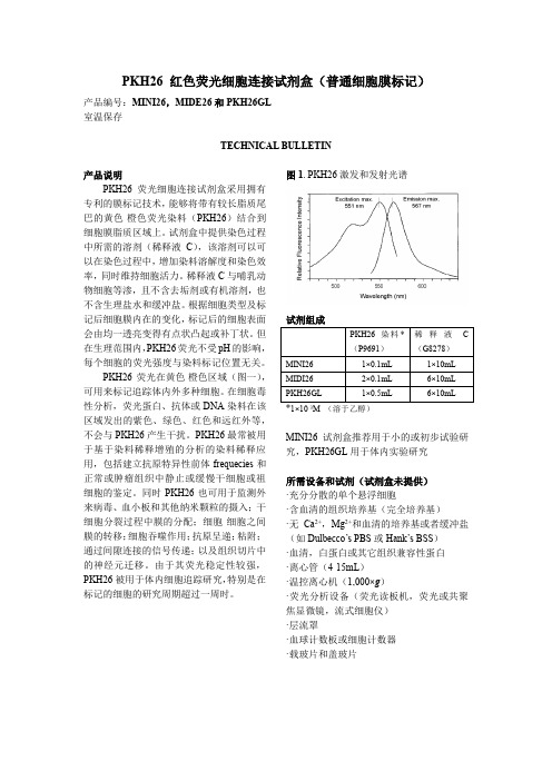
PKH26 红色荧光细胞连接试剂盒(普通细胞膜标记)产品编号:MINI26,MIDE26和PKH26GL室温保存TECHNICAL BULLETIN产品说明PKH26荧光细胞连接试剂盒采用拥有专利的膜标记技术,能够将带有较长脂质尾巴的黄色-橙色荧光染料(PKH26)结合到细胞膜脂质区域上。
试剂盒中提供染色过程中所需的溶剂(稀释液C),该溶剂可以可以在染色过程中,增加染料溶解度和染色效率,同时维持细胞活力。
稀释液C与哺乳动物细胞等渗,且不含去垢剂或有机溶剂,也不含生理盐水和缓冲盐。
根据细胞类型及标记后细胞膜内在的变化,标记后的细胞表面会由均一透亮变得有点状凸起或补丁状。
但在生理范围内,PKH26荧光不受pH的影响,每个细胞的荧光强度与染料标记位置无关。
PKH26荧光在黄色-橙色区域(图一),可用来标记追踪体内外多种细胞。
在细胞毒性分析,荧光蛋白、抗体或DNA染料在该区域发出的紫色、绿色、红色和远红外等,不会与PKH26产生干扰。
PKH26最常被用于基于染料稀释增殖的分析的染料稀释应用,包括建立抗原特异性前体frequecies和正常或肿瘤组织中静止或缓慢干细胞或祖细胞的鉴定。
同时PKH26也可用于监测外来病毒、血小板和其他纳米颗粒的摄入;干细胞分裂过程中膜的分配;细胞-细胞之间膜的转移;细胞吞噬作用;抗原呈递;粘附;通过间隙连接的信号传递;以及组织切片中的神经元迁移。
由于其荧光稳定性较强,PKH26被用于体内细胞追踪研究,特别是在标记的细胞的研究周期超过一周时。
图1. PKH26激发和发射光谱1×10⁻³M (溶于乙醇)MINI26试剂盒推荐用于小的或初步试验研究,PKH26GL用于体内实验研究所需设备和试剂(试剂盒未提供)·充分分散的单个悬浮细胞·含血清的组织培养基(完全培养基)·无Ca2+,Mg2+和血清的培养基或者缓冲盐(如Dulbecco’s PBS或Hank’s BSS)·血清,白蛋白或其它组织兼容性蛋白·离心管(4-15mL)·温控离心机(1,000×g)·荧光分析设备(荧光读板机,荧光或共聚焦显微镜,流式细胞仪)·层流罩·血球计数板或细胞计数器·载玻片和盖玻片注意事项和免责说明该产品仅用于科研,不用于制药、家庭或其它用途。
- 1、下载文档前请自行甄别文档内容的完整性,平台不提供额外的编辑、内容补充、找答案等附加服务。
- 2、"仅部分预览"的文档,不可在线预览部分如存在完整性等问题,可反馈申请退款(可完整预览的文档不适用该条件!)。
- 3、如文档侵犯您的权益,请联系客服反馈,我们会尽快为您处理(人工客服工作时间:9:00-18:30)。
T-13/4 (5 mm) Precision Optical Performance AlInGaP LED LampsTechnical DataFeatures• Well Defined Spatial Radiation Patterns• Viewing Angles: 6°, 15°, 23°, 30°• High Luminous Output• Colors:590 nm Amber605 nm Orange615 nm Reddish-Orange626 nm Red• High Operating Temperature:T J LED=+130°C• Superior Resistance to Moisture• Four Package Options:With or Without Flange Base; With or Without Lead Stand-OffsBenefits• Viewing Angles Match Traffic Management Sign Requirements• Colors Meet Automotive and Pedestrian Signal Specifications• Superior Performance in Outdoor Environments• Suitable for Autoinsertion onto PC Boards Applications• Traffic Management:Traffic SignalsPedestrian SignalsWork Zone Warning LightsVariable Message Signs• Commercial OutdoorAdvertising:SignsMarquees• Automotive:Exterior and Interior LightsDescriptionThese Precision Optical Perform-ance AlInGaP LEDs providesuperior light output for excellentreadability in sunlight and areextremely reliable. AlInGaP LEDtechnology provides extremelystable light output over longperiods of time. Precision OpticalPerformance lamps utilize thealuminum indium gallium phos-phide (AlInGaP) technology.These LED lamps are untinted,nondiffused, T-13/4 packagesincorporating second generationoptics producing well definedspatial radiation patterns atspecific viewing cone angles.SunPower SeriesHLMP-DLXXHLMP-DJXXHLMP-DHXXHLMP-DGXXHLMP-GLXXHLMP-GJXXThese lamps are made with anadvanced optical grade epoxy,offering superior high tempera-ture and high moisture resistanceperformance in outdoor signaland sign applications. The highmaximum LED junction tempera-ture limit of +130°C enables hightemperature operation in brightsunlight conditions. The packageepoxy contains both uv-a anduv-b inhibitors to reduce theeffects of long term exposure todirect sunlight.These lamps are available in fourpackage options to give thedesigner flexibility with devicemounting.HLMP-GHXXHLMP-GGXXHLMP-ULXXHLMP-UJXXHLMP-UHXXHLMP-UGXXDevice Selection GuideColor,Luminous Intensity,Part Typical Dominant I v (mcd),[1,2]Number Viewing Angle,Wavelength,@ 20 mA Leads with Flanged Package HLMP-2θ1/2 (Deg.)[4]λd (nm),[3] Typ.Min.Typ.Stand-Offs Base Drawing DL08[5]6Amber, 59040009300No Yes A GL08[5]6Amber, 59040009300No No B DL10[5]6Amber, 59040009300Yes Yes C GL10[5]6Amber, 59040009300Yes No D UL06[5]6Amber, 59016004000No Yes A UL07[5]6Amber, 59016004000Yes Yes C DJ08[5]6Orange, 60542009500No Yes A GJ08[5]6Orange, 60542009500No No B DJ10[5]6Orange, 60542009500Yes Yes C GJ10[5]6Orange, 60542009500Yes No D UJ06[5]6Orange, 60520004500No Yes A UJ07[5]6Orange, 60520004500Yes Yes C DH08[5]6Red-Orange, 61529008000No Yes A GH08[5]6Red-Orange, 61529008000No No B DH10[5]6Red-Orange, 61529008000Yes Yes C GH10[5]6Red-Orange, 61529008000Yes No D UH06[5]6Red-Orange, 61514003500No Yes A UH07[5]6Red-Orange, 61514003500Yes Yes C DG08[5]6Red, 62629006500No Yes A GG08[5]6Red, 62629006500No No B DG10[5]6Red, 62629006500Yes Yes C GG10[5]6Red, 62629006500Yes No D UG06[5]6Red, 62610003000No Yes A UG07[5]6Red, 62610003000Yes Yes C DL1515Amber, 59016003100No Yes A GL1515Amber, 59016003100No No B DL1715Amber, 59016003100Yes Yes C GL1715Amber, 59016003100Yes No D UL1315Amber, 590 7001600No Yes A UL1415Amber, 590 7001600Yes Yes C DJ1515Orange, 60514003400No Yes A GJ1515Orange, 60514003400No No B DJ1715Orange, 60514003400Yes Yes C GJ1715Orange, 60514003400Yes No DNotes:1. The luminous intensity is measured on the mechanical axis of the lamp package.2. The optical axis is closely aligned with the package mechanical axis.3. The dominant wavelength, λd, is derived from the CIE Chromaticity Diagram and represents the color of the lamp.4. θ1/2 is the off-axis angle where the luminous intensity is one half the on-axis intensity.5. The intensity of narrow viewing angle lamps is measured at the intensity peak.Device Selection Guide, continuedColor,Luminous Intensity,Part Typical Dominant I v (mcd),[1,2]Number Viewing Angle,Wavelength,@ 20 mA Leads with Flanged Package HLMP-2θ1/2 (Deg.)[4]λd (nm),[3] Typ.Min.Typ.Stand-Offs Base Drawing UJ1315Orange, 605 7001800No Yes A UJ1415Orange, 605 7001800Yes Yes C DH1515Red-Orange, 61514002500No Yes A GH1515Red-Orange, 61514002500No No B DH1715Red-Orange, 61514002500Yes Yes C GH1715Red-Orange, 61514002500Yes No D UH1315Red-Orange, 615 5001400No Yes A UH1415Red-Orange, 615 5001400Yes Yes C DG1515Red, 62614002100No Yes A GG1515Red, 62614002100No No B DG1715Red, 62614002100Yes Yes C GG1715Red, 62614002100Yes No D UG1315Red, 626 500 1000No Yes A UG1415Red, 626 500 1000Yes Yes C DL2423Amber, 59010001800No Yes A GL2423Amber, 59010001800No No B DL2623Amber, 59010001800Yes Yes C GL2623Amber, 59010001800Yes No D UL2223Amber, 590 450 1000No Yes A UL2323Amber, 590 450 1000Yes Yes C DJ2423Orange, 605 10002000No Yes A GJ2423Orange, 605 10002000No No B DJ2623Orange, 605 10002000Yes Yes C GJ2623Orange, 60510002000Yes No D UJ2223Orange, 605 2901200No Yes A UJ2323Orange, 605 290 1200Yes Yes C DH2423Red-Orange, 615 700 1500No Yes A GH2423Red-Orange, 615 700 1500No No B DH2623Red-Orange, 615 700 1500Yes Yes C GH2623Red-Orange, 615 700 1500Yes No D UH2223Red-Orange, 615 290 900No Yes A UH2323Red-Orange, 615 290 900Yes Yes CNotes:1. The luminous intensity is measured on the mechanical axis of the lamp package.2. The optical axis is closely aligned with the package mechanical axis.3. The dominant wavelength, λd, is derived from the CIE Chromaticity Diagram and represents the color of the lamp.4. θ1/2 is the off-axis angle where the luminous intensity is one half the on-axis intensity.5. The intensity of narrow viewing angle lamps is measured at the intensity peak.Device Selection Guide, continuedColor,Luminous Intensity,Part Typical Dominant I v (mcd),[1,2]Number Viewing Angle,Wavelength,@ 20 mA Leads with Flanged Package HLMP-2θ1/2 (Deg.)[4]λd (nm),[3] Typ.Min.Typ.Stand-Offs Base Drawing DG2423Red, 626 7001300No Yes A GG2423Red, 626 7001300No No B DG2623Red, 626 7001300Yes Yes C GG2623Red, 626 7001300Yes No D UG2223Red, 626 290 700No Yes A UG2323Red, 626 290 700Yes Yes C DL3030Amber, 590 7001300No Yes A GL3030Amber, 590 7001300No No B DL3230Amber, 590 7001300Yes Yes C GL3230Amber, 590 7001300Yes No D UL2830Amber, 590 300 750No Yes A UL2930Amber, 590 300 750Yes Yes C DJ3030Orange, 605 7001500No Yes A GJ3030Orange, 605 7001500No No B DJ3230Orange, 605 7001500Yes Yes C GJ3230Orange, 605 7001500Yes No D UJ2830Orange, 605 200 800No Yes A UJ2930Orange, 605 200 800Yes Yes C DH3030Red-Orange, 615 5001100No Yes A GH3030Red-Orange, 615 5001100No No B DH3230Red-Orange, 615 5001100Yes Yes C GH3230Red-Orange, 615 5001100Yes No D UH2830Red-Orange, 615 200 600No Yes A UH2930Red-Orange, 615 200 600Yes Yes C DG3030Red, 626 500 900No Yes A GG3030Red, 626 500 900No No B DG3230Red, 626 500 900Yes Yes C GG3230Red, 626 500 900Yes No D UG2830Red, 626 200 500No Yes A UG2930Red, 626 200 500Yes Yes CNotes:1. The luminous intensity is measured on the mechanical axis of the lamp package.2. The optical axis is closely aligned with the package mechanical axis.3. The dominant wavelength, λd, is derived from the CIE Chromaticity Diagram and represents the color of the lamp.4. θ1/2 is the off-axis angle where the luminous intensity is one half the on-axis intensity.5. The intensity of narrow viewing angle lamps is measured at the intensity peak.DCPackage DimensionsBAPART NO.d HLMP-XX10 -XX0712.37 ± 0.25(0.487 ± 0.010)HLMP-XX17 -XX1412.42 ± 0.25(0.489 ± 0.010)HLMP-XX26 -XX2312.52 ± 0.25(0.493 ± 0.010)HLMA-XX32 -XX2911.96 ± 0.25(0.471 ± 0.010)(0.039)(0.039)MAX.(0.039)2.54 ± 0.380.50 ± 0.10SQ. TYP.NOTES:1. ALL DIMENSIONS ARE IN MILLIMETERS (INCHES).2. LEADS ARE MILD STEEL, SOLDER DIPPED.3. TAPERS SHOWN AT TOP OF LEADS (BOTTOM OF LAMP PACKAGE) INDICATE AN EPOXY MENISCUS THAT MAY EXTEND ABOUT 1 mm (0.040 in.) DOWN THE LEADS.4. RECOMMENDED PC BOARD HOLE DIAMETERS:• LAMP PACKAGES A AND B WITHOUT STAND-OFFS: FLUSH MOUNTING AT BASE OF LAMP PACKAGE = 1.143/1.067 (0.044/0.042).• LAMP PACKAGES C AND D WITH STAND-OFFS: MOUNTING AT LEAD STAND-OFFS = 0.965/0.889 (0.038/0.035).5. FOR DOME HEIGHTS ABOVE LEAD STAND-OFF SEATING PLANE, d, LAMP PACKAGESC AND D, SEE TABLE.(0.039)2.54 ± 0.38SQ. TYP.Electrical/Optical Characteristics at T A = 25°CParameter SymbolMin.Typ.Max.UnitsTest Conditions Forward VoltageI F = 20 mAAmber (λd = 590 nm) 2.02Orange (λd = 605 nm)V F 1.98 2.4VRed-Orange (λd = 615 nm) 1.94Red (λd = 626 nm) 1.90Reverse Voltage V R 520VI F = 100 µAPeak Wavelength:Peak of Wavelength of Amber (λd = 590 nm)592Spectral Distribution Orange (λd = 605 nm)λPEAK609nmat I F = 20 mARed-Orange (λd = 615 nm)621Red (λd = 626 nm)635Spectral Halfwidth∆λ1/217nmWavelength Width at Spectral Distribution 1/2 Power Point at I F = 20 mASpeed of Response τs 20ns Exponential Time Constant, e -t/τCapacitanceC 40pF V F = 0, f = 1 MHzThermal Resistance R θJ-PIN240°C/WLED Junction-to-Cathode LeadLuminous Efficacy [1]Emitted LuminousAmber (λd = 590 nm)480Power/Emitted Radiant Orange (λd = 605 nm)ηv370lm/WPowerRed-Orange (λd = 615 nm)260Red (λd = 626 nm)150Note:1. The radiant intensity, I e , in watts per steradian, may be found from the equation I e = I v /ηv , where I v is the luminous intensity in candelas and ηv is the luminous efficacy in lumens/watt.Absolute Maximum Ratings at T A = 25°CDC Forward Current [1,2,3]............................................................50 mA Peak Pulsed Forward Current [2,3]................................................70 mA Average Forward Current [3].........................................................30 mA Reverse Voltage (I R = 100 µA).........................................................5 V LED Junction Temperature..........................................................130°C Operating Temperature ..............................................-40°C to +100°C Storage Temperature ..................................................-40°C to +120°C Soldering Temperature ..........................................260°C for 5 seconds [1.59 mm (0.060 in.) below seating plane]Notes:1. Derate linearly as shown in Figure 4.2. For long term performance with minimal light output degradation, drive currents between 10 mA and 30 mA are recommended.3. Please contact your Hewlett-Packard sales representative about operating currents below 10 mA.sFigure 2. Forward Current vs.Forward Voltage.Figure 3. Relative Luminous Intensity vs. Forward Current.Figure 4. Maximum Forward Current vs. Ambient Temperature. Derating Based on T JMAX = 130°C.Figure 1. Relative Intensity vs. Peak Wavelength.Figure 5. Representative Spatial Radiation Pattern for 6° Viewing Angle Lamps.WAVELENGTH – nmR E L A T I V E I N T E N S I T YI F – F O R W A R D C U R R E N T – m AT A – AMBIENT TEMPERATURE – °CR E L A T I V E I N T E N S I T Y – %1000θ – ANGULAR DISPLACEMENT – DEGREES8060507020-20-15103040-1051015202590-25-5C U R RE N T – m AV F – FORWARD VOLTAGE – V R E L A T I V E L U M I N O U S I N T E N S I T Y (N O R M A L I Z E D A T 20 m A )00I F – DC FORWARD CURRENT – mA 403.02.01.51.00.520602.5For technical assistance or the location of your nearest Hewlett-Packard sales office, distributor or representative call: Americas/Canada: 1-800-235-0312 or 408-654-8675Far East/Australasia: (65) 290-6305 Japan: (81 3) 3335-8152Europe: Call your local HP sales office. Data subject to change.Copyright © 1997 Hewlett-Packard Co. Obsoletes 5965-5265EPrinted in U.S.A.5965-6807E (1/97)。