贝克的封隔器Packer_FB3
8、KE3004中文说明书(天津贝克)

在腔室的右侧有本安型显示单元和接线腔,腔室上有两个显示单元分别对应着隔爆腔室中的两个插入模块。显示单元显示所有必要的信息,操作状态、错误信息和实际输出的电流值。在每个隔爆腔室内提供以下元气件:
动力母线回路板
模块辅助回路的连接电缆(带有端子)
两路接触器模块
两路用于把动力输出接地的隔离机构
98/37/EC:机械设备
89/336/EC:电磁兼容
2.4.2标准
EN50014-1977+A1到A5:通用要求
EN50018-1977+A1到A3:防爆外壳“d”
EN50020-1977+A1到A5:本质安全“i”
EN50028-1987:浇封型“m”
2.4.3规定
VDE118:井下电气安装规定
人员对此设备进行操作时要格外小心
谨防挤压
此危险标记指示此设备相当危险,如果不按规程操作有可能致人死亡、严重伤残或对财产造成损坏
人员对此设备进行操作时要格外小心
警告!防止烫伤
此危险标记表明设备表面很热。接触其表面可能会烫伤人体。
警告:高压
对此设备进行处理的人员必须有必要的能力(例如:电气技师),而且要有公司的授权
3.3.1井下安装
3.3.1.1安装环境条件
3.4安装说明
3.4.1设备安装
3.4.1.1电气连接
3.4.1.1.1输入及输出连接
3.4.1.1.2本安回路连接
3.4.1.2控制单元
3.4.1.3显示单元
3.4.2用前准备
3.4.2.1系统集成
3.4.2.2安全措施
3.4.2.3连接回路
3.4.3操作指导
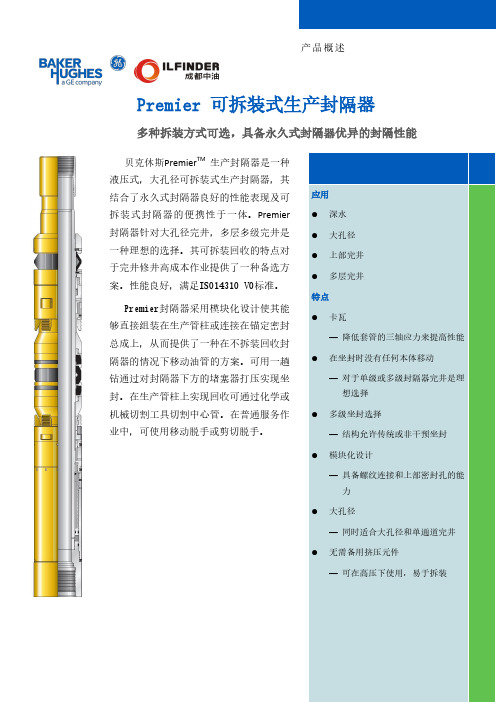
Premier可拆装式生产封隔器
in.
mm
3.625
92.1
4.750
120.7
3.625
92.1
4.750
120.7
3.625
92.1
4.750
120.7
3.625
92.1
4.750
120.7
6.000 4.750 6.000 4.750 7.375 6.000 10.183 10.183
155.8 120.7 155.8 120.7 187.3 155.8 258.6 258.6
最大外径
in.
mm
4.500
114.3
5.820
147.8
5.910
150.1
5.983
152.0
6.450
163.8
6.590
167.4
8.310
211.1
8.450
214.6
9.345
237.3
12.090 12.090
307.1 307.1
•5.500尺寸是ISO 14310 V3认定的 *AFLASTM 是日本旭硝子玻璃股份有限公司的品牌商标
最小外径
in.
mm
2.390
60.7
3.875
98.4
3.760
95.5
2.870
72.9
3.875
98.4
3.760
95.5
2.870
72.9
3.875
98.4
3.760
95.5
2.870
72.9
3.875
98.4
3.760
95.5
3.875
98.4
Frac+Point+Presentation贝克分段压裂工具
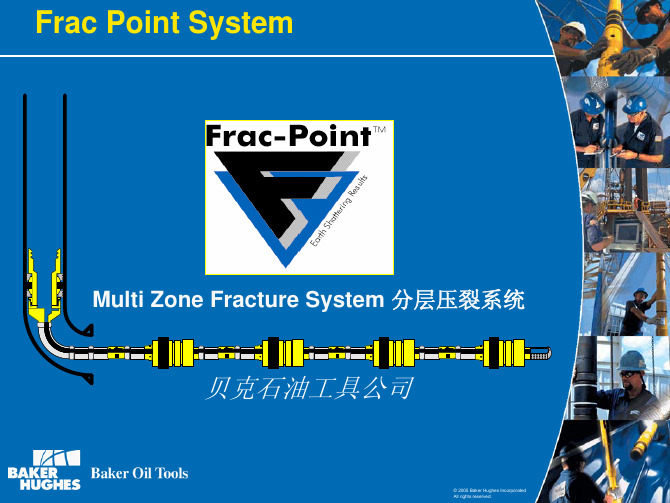
Four Element Packing System四个胶筒 Expandable Metal Back Up Rings 膨胀式金属
支撑环
Job number here-21
© 2005 Baker Hughes Incorporated All rights reserved.
Ball Activated Frac Sleeve 投球开关滑套
Well Name 井名
Well Frac Point Well 压裂井 Well #1 Well #2 Well #3 Well #4 Well #5 Well #6 Well #7
Initial Production Rate (mcf) 产量
Initial Production Rate of Frac Point Well vs Offset Vertical Fractured Wells
实现压裂作业井段横向分段隔离
Create fractures over the entire length of the lateral
实现全井段完全压裂作业
Increase NPV 增加投资回报率 ¾ Higher initial rate of production 提高产量 ¾ Increased reservoir drainage 增加采收率 ¾ Lower operational expenses降低作业成本
3000 2500
2753
IP (m cf)
Knowles 2-26-H McGee 1-35 Hillis 1-27 Hildreth 1-36 Cassell 1-26 Koone 1-34 Knowles 1-26 Koone 2-35
封隔器的特点与原理课件

Y241-100封隔器
封隔器的特点与原理
一、用途
该 封 隔 器 主 要 用 于 51/2″ 套 管变形的油、水井卡层。
二、工作原理
1、坐封:将封隔器用油管
输送至设计井段。油管内加压5 MPa时,防坐封剪钉被剪断, 上活塞带动缸套及压紧套上行, 压缩胶筒,同时分瓣爪被释放, 在下活塞的推动下,下行推动 锥体,撑开卡瓦,咬住套管壁, 当压力逐渐增大至15 MPa时, 胶筒完全被压缩,密封油套环 形空间,此时,缸套被锁环紧 紧锁住,使胶筒无法弹回,始 终处于密封状态。
封隔器的特点与原理
5)洗井:在需要洗井时,从油套环形空间进行洗
井液,此时由于压差作用,打开封隔器上部的洗井 阀,洗井液由内外中心管环形空间穿过封隔器,再 由低部球座进入油管返到井口,形成洗井通到达到 洗井的目的。
6)解封:上提管柱,由于封隔件与套管是贴紧的
有摩擦力,此时内中心管上行,带动解封套上行收 缩分瓣爪,分瓣爪不能锁住封隔件,在封隔件回弹 力的作用下,封隔件收回不再贴紧套管,从而使封 隔器解封。
封隔器的特点与原理
四、注意事项:
1.封隔器下井前应用相应的通井规通井,用套 管刮 削器进行刮削作业。
2.所选用的封隔器是否与所适用的套管规格相 符。
3.封隔器的坐封位置要避开套管接箍。 4.封隔器的下入速度应维持在每根不应少于10
秒,且速度要均匀。 5.下井前要检查封隔器换轨是否灵活、可靠。
封隔器的特点与原理
Y441-115(B)丢手封隔 器
封隔器的特点与原理
一、用途与特点:
该封隔器主要用于油、水井卡堵底层,若将丢手部分 去掉,也可用于分层采油,具有如下特点:
1、采用双锥体双向卡瓦锚定机构,具有锚定可靠, 承受负荷大的特性。。
永久封隔器完成程序
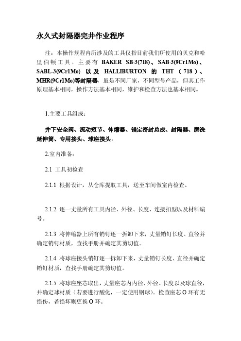
永久式封隔器完井作业程序注:本操作规程内所涉及的工具仅指目前我们所使用的贝克和哈里伯顿工具。
主要有BAKER SB-3(718)、SAB-3(9Cr1Mo)、SABL-3(9Cr1Mo) 以及HALLIBURTON的THT(718)、MHR(9Cr1Mo)等封隔器,虽是不同厂家,不同型号产品,但其工作原理基本相同,操作方法基本相同,维护和检查方法也基本相同。
1.主要工具组成:井下安全阀、流动短节、伸缩器、锚定密封总成、封隔器、磨洗延伸筒、专用接头、球座接头。
2.室内准备:2.1 工具初检查2.1.1 根据设计,从仓库提取工具,送至车间做室内检查。
2.1.2 逐一丈量所有工具内径、外径、长度、连接扣型以及材料编号。
2.1.3 将伸缩器上所有销钉逐一拆卸下来,丈量销钉长度、直径并确定销钉材质,查找手册并确定其剪切值。
2.1.4 将球座接头销钉逐一拆卸下来,丈量销钉长度、直径并确定销钉材质,查找手册确定其剪切值。
2.1.5 将球座座芯取出,丈量座芯内内径、外径、长度以及球直径,并确定球材质(若要进行酸化,一定使用钢球)。
检查座芯O环有无损伤,若损坏则更换O环。
2.1.6 检查封隔器胶筒有无损伤,并确定封隔器启动销钉、卡瓦销钉等都齐全。
2.1.7 检查井下安全阀毛细管SWAGELOC接头等是否齐全。
2.2 连接2.2.1 从上到下将锚定式密封总成+封隔器+磨洗延伸筒+变扣短节连接成串。
注:a.锚定式密封总成与封隔器为反扣连接,连接时应左旋上扣。
b.目前,贝克和哈里伯顿的718材质的封隔器都没有配合的锚定密封总成及磨洗延伸筒。
2.2.2 从上至下依次连接上流动短节+井下安全阀+下流动短节。
注:上流动短节与下流动短节均为相同产品,只是连接位置不同而取不同的名字。
2.3 试压2.3.1 将伸缩器置于拉压机上,中部用支撑架支撑,根据产品手册规定的试压值进行试压。
注:施压时,伸缩器会自动伸长,此时应随时调整支撑架位置,防止工具过度弯曲。
Halliburton EZSV派克和裸眼挤水泥封隔器及座封工具使用指南

EZSV和EZSV裸眼挤水泥封隔器及座封工具使用指南零件号:802.00005EZSV及EZSV裸眼挤水泥封隔器(下称EZSV派克和裸眼派克)是为控制其上下双向的流体运动而设计的,这种运动是通过一个压力平衡式的滑阀(sliding value)控制的。
在挤水泥前后,通过上下活动油管,可以方便的开关滑阀。
当滑阀处于关闭位置时(上方),座封的派克就隔绝了它上、下流体的流动;当滑阀处于打开位置时(下方),则可以把流体挤入下部井眼或释放其下圈闭的压力,同时,流体通过的不会改变滑阀的位置。
当滑阀开启时,通过派克上的侧孔,会形成一个自由的流体通道。
由于只有很小一部分外表面接触水泥浆,故滑阀不会被固死在那儿个地方。
滑阀可以通过下放管串重量而打开,通过上提管串而关闭。
管串的上下活动能够准确无误地开、关滑阀。
当位于关闭位置时,滑阀上部一个可开合的指形环(collapsible fingers)是自由张开在派克心轴内壁上的一个凹槽切口内的。
在下放管串时,司丁克(stinger)的下缘触在滑阀和指形环连接处的内倒角上,把滑阀下推到打开位置,同时,指形环也由切口锲入心轴内并且抱住司丁克下端的加厚啮合头(profile)。
上提管串则(以相反的过程)把滑阀拉出关闭。
此时,指形环又展开到切口且松开司丁克,这样就能提出司丁克而滑阀则仍锁死在关闭位置了。
EZSV派克能用油管、钻杆和电缆座封工具座封,而EZSV裸眼派克则只能用油管和钻杆。
使用电缆座封的EZSV派克时,请向哈里伯顿工具工程师咨询适当的工具接头以匹配不同的座封工具。
EZSV裸眼派克绝不能用电缆或钢丝座封工具来座封,因为这些工具没有座封派克所需要的足够长的作用距离。
座封工具EZSV座封工具主要是为操作EZSV派克而设计的,但它也能通过更换座封工具的下心轴(即通常所谓的stinger)以改装成EZSV裸眼派克的座封工具。
EZSV裸眼派克的滑阀在心轴内腔中比EZSV派克的深,因此,EZSV座封工具需要一个较长的插入头来操作裸眼派克。
(贝克休斯的关于裸眼封隔器的材料)

Run Liner Assy to Depth, Correlate, Hang, Circulate Hole Volume w/ DIF
Set Liner Top Packer
Pull up Inner String, Set MPas Packers
Pull Above Liner Top, Spot Spacers, Displace Casing w/ Brine
© 2005 Baker Hughes Incorporated All rights reserved.
9-1/2” x
MPas™ Packer Specifications
Size : 4-1/2” Maximum Packer O.D. : 5.625” Minimum ID : 3.8” Setting Mechanism: Hydrostatic / Hydraulic Tested w/ 4,100 psi Hydrostatic + 3,000 psi Hydraulic Setting Pressure Cylinder Collapse Rating: 7,500 psi (80ksi MYS) Mandrel Burst Rating: 8,440 psi (80ksi MYS) Mandrel Tensile Strength: 289,000 # (80ksi MYS) Setting Tool Required: Workstring Cup Tool Maximum Ovality Tested (to date): 6” x 7-1/2”
© 2005 Baker Hughes Incorporated All rights reserved.
Example Installation Sequence
封隔器

封隔器
封隔器Packer 是指用来密封管柱(或裸眼井壁)与管柱之间环空,隔离目的层段,控制注入或采出流体,并能承受压差的井下工具。
(位于射孔井段的顶端)
封隔器封隔件实现密封的方式进行分类。
自封式:靠封隔件外径与套管内径的过盈和工作压差实现密封的封隔器。
压缩式:靠轴向力压缩封隔件,使封隔件外径变大实现密封的封隔器。
扩张式:靠径向力作用于封隔件内腔,使封隔件外径扩大实现密封的封隔器。
组合式:由自封式、压缩式、扩张式任意组合实现密封的封隔器。
Mechanical packer
Packer. There are many types and designs of packer in common use in oil and gas operations. In each case, the principal function is to isolate the annulus from the tubing conduit to enable controlled production, injection or treatment. The mechanical packer shown here is used to isolate zones during stimulation treatments.。
封隔器技术说明
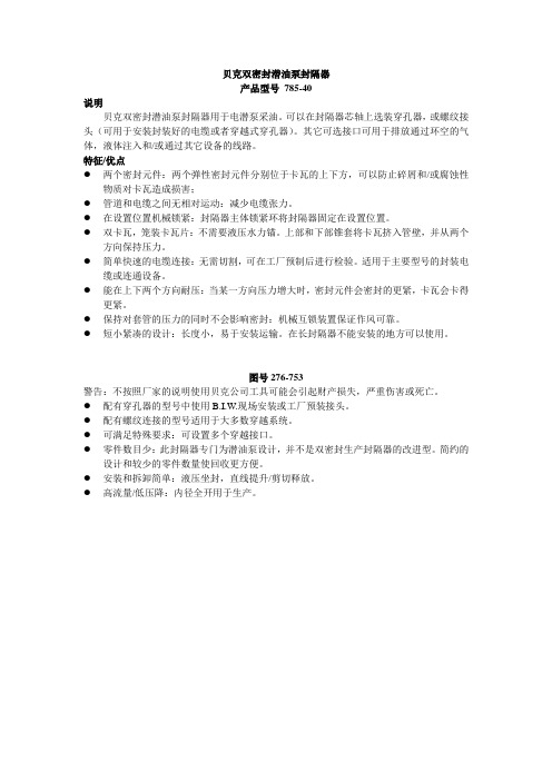
贝克双密封潜油泵封隔器产品型号785-40说明贝克双密封潜油泵封隔器用于电潜泵采油。
可以在封隔器芯轴上选装穿孔器,或螺纹接头(可用于安装封装好的电缆或者穿越式穿孔器)。
其它可选接口可用于排放通过环空的气体,液体注入和/或通过其它设备的线路。
特征/优点●两个密封元件:两个弹性密封元件分别位于卡瓦的上下方,可以防止碎屑和/或腐蚀性物质对卡瓦造成损害;●管道和电缆之间无相对运动:减少电缆张力。
●在设置位置机械锁紧:封隔器主体锁紧环将封隔器固定在设置位置。
●双卡瓦,笼装卡瓦片:不需要液压水力锚。
上部和下部锥套将卡瓦挤入管壁,并从两个方向保持压力。
●简单快速的电缆连接:无需切割,可在工厂预制后进行检验。
适用于主要型号的封装电缆或连通设备。
●能在上下两个方向耐压:当某一方向压力增大时,密封元件会密封的更紧,卡瓦会卡得更紧。
●保持对套管的压力的同时不会影响密封:机械互锁装置保证作风可靠。
●短小紧凑的设计:长度小,易于安装运输。
在长封隔器不能安装的地方可以使用。
图号276-753警告:不按照厂家的说明使用贝克公司工具可能会引起财产损失,严重伤害或死亡。
●配有穿孔器的型号中使用B.I.W.现场安装或工厂预装接头。
●配有螺纹连接的型号适用于大多数穿越系统。
●可满足特殊要求:可设置多个穿越接口。
●零件数目少:此封隔器专门为潜油泵设计,并不是双密封生产封隔器的改进型。
简约的设计和较少的零件数量使回收更方便。
●安装和拆卸简单:液压坐封,直线提升/剪切释放。
●高流量/低压降:内径全开用于生产。
规格表作的封隔器,根据要求可使用高性能材料和弹性体。
下井和设置步骤双密封封隔器的坐封通过给管柱内加压完成。
在封隔器的芯轴下端要装座节,球座,水力活塞接头,或者其他暂时型的封堵设备。
1.将封隔器下入设定的深度。
2.将连接芯轴的管线暂时封堵。
3.缓慢升压到2500PSI剪断所有销钉使封隔器坐封。
稳压两分钟。
4.缓慢降压致1000PSI,在套管上加压到1500PS I◆。
贝克休斯封隔器

,
^
>
(449-40)
QAKEJ*
B M £d ^ . l ^H-M^r^^l I ^ H ^ H FORMULA "B" TUBING SEAL GREASE (499-26) Snou|d be app|jed to the seal areas of packer accessories to fill the spaces between the accessory and packer bore to keep out particles that might interfere with the seal or with removal of the accessory.
Infrared Spectrometers Provide chemical analysis of elastomer components.
Manufacturing Locations
CAD/CAM Techniques Are used to optimize product design and manufacturing
1| • l •4 |B •
•
• •
=& B 1| • -W BE 1 •
MODEL "K" LOCATOR TUBING SEAL NIPPLE (442-51) Used for landing and sealing in the upper bore Models
SEAL BORE EXTENSION
Permanent Packer Systems
Tubing Seal Systems
Baker provides an array of tubing seal assemblies desioned tO ^cwtrnmnrlatfa thfa environmental requirements of present and future well conditions. Baker products address the problems associated with pressure, temperature, well fluids and seal movement. These environmental considerations will determine the best combination of seal (elastomer), accessory material (steel) and accessory type (locator, anchor or other) for use in each case.
blackcat威德福封隔器说明书

BlackCat Retrievable Sealbore Packer-WFX The Weatherford BlackCat WFX Retrievable Sealbore Packer is a reliable, high-pressure packer is specifically intended for use as a gravel pack packer, but can be used for production, stimulation, or injection applications. The BlackCat is normally set on tubing with a WFX hydraulic setting tool, and it may be retrieved with a pulling tool on a workstring. Rotationally locked components ease milling when retrieval is not possible. The BlackCat’s patented ECNER Array packing element system is designed for high pressure and resists swab-off. The BlackCat shares accessories with the UltraPak Permanent Packer system.Features•High-pressure ECNER Array packing element system•Tested to ISO 14310 levels in Q-125 casing•Conveyed on tubing or wireline•Rotationally locked for ease in milling•Retrieval mechanism protected from debris•Materials available suitable for hostile environments•No rotation required running or retrieving the packer•Slips below element simplify retrieval•Uses the same accessories as the UltraPak Permanent Packer System •Castellated setting sleeve for torque through capabilityBenefits•Reliable, dependable field-proven design•Easy to retrieve and redress•High performance in compact size•Versatile packer with wide selection of accessories and materials Applications•High-pressure production or injection•Anchored or floating seal applications•High-rate gravel packing•Stimulation and fracturing•TCP guns suspended below a packer•Deviated and horizontal wellsSPECIFICATION GUIDESPECIFICATION GUIDESPECIFICATION GUIDECAUTION:Before starting work, ensure all personal protection equipment is available and being used. Evaluate job site to ensure work can be completed safely. All safety procedures are to be observed.PRE-RUN INSPECTION1. Inspect packing element for cuts, cracks or shipping damage.2. Verify O.D. of packing element is below O.D. of gage rings.3. Verify slips are not protruding above slip cage O.D.4. Ensure all shear screws and set screws are installed.PRECAUTIONS AND HANDLING1. Do not lift tool at packing element and slip locations.2. Running speed should not exceed 60 ft/min.3. Place a back-up on bottom when installing equipment below packer.SETTING PROCEDURERun the Weatherford BlackCat WFX with gravel pack extension and screen to setting depth on tubing using a hydraulic setting tool. [Size 70 WFX Hydraulic Setting Tool with (7.0” Adapter Kit 00906785). When used in a gravel pack application, the seats for the setting tool are normally contained in the crossover tool. In its normal configuration, drop the primary setting ball and allow it to gravitate to the shearable ball seat. Pressure up until observing the startto set shear pins shear. Hold the pressure for five minutes. Increase pressure in 500-psi increments and hold at each stage for five minutes. Increase pressure until the desired setting pressure is reached. When run on tubing using a hydraulic setting tool, a maximum running speed of 90 feet per/minute should be used. When running in heavier fluids, a slower running speed should be considered.If it is desired to run this packer on wireline, refer to the standard BlackCat tech unit for wireline setting kit information. Maximum recommended running speed on wireline, 180 feet/minute.RELEASING PROCEDUREThe retrieving tool is run in the hole and set down force is applied when the packer is contacted. Applying 2,000 to 3,000 lb. down force is sufficient to fully latch the retrieving tool into the packer. At this point, the release collet is positioned directly below the support ring of the packer. Straight pull will engage the release collet and the support ring. Tension force is applied which will shear screws in the support ring and shift it upward thus releasing the packer. If the support ring does not shear out easily, there is a built in jar stroke in the retrieving tool. By jarring upward, either the support ring will shear or the shear ring in the retrieving tool will shear. This is a safety shear, allowing the retrieving tool to be rotated free of the packer if the packer will not release. If this is necessary, pull slight tension and rotate to the right approximately 8 turns at the packer to release the retrieving tool from the packer. The shear value of the shear ring is adjustable and should be considered prior to running the retrieving tool.STORAGEStore in a cool dry place out of direct sun light. Wrap slips and packing element with bubble wrap or cardboard and tape in place to protect element and slips from damage. Wrap packer with wax coated pump wrap to prevent corrosion for extended storage.TORQUE THROUGH CAPABILITYThis version of the BlackCat Packer has a modified torque lock feature allowing torque to be transmitted through the packer, bypassing the external components. This feature is regularly required to get liner assemblies into liner tops or getting past obstructions in highly deviated open hole sections.The castellated setting sleeve is designed to mate up with drive sleeves used with the WFX Setting Tool. Torque transmitted through the setting tool is transferred to the packer through the setting sleeve. The torque continues through the cap screws, into the top body, mandrel, collet and through the shear screws into the bottom housing. From this point it would be transmitted into the bottom hole assembly through threaded connections.TORQUE LIMITS FOR THE MAJOR TORQUE TRANSMISSION POINTSBOTTOM SUBTo keep this packer most versatile, the assembly is left with a stub acme box down on the bottom housing. In order to be used in its normal application, a separate bottom sub will have to be installed. Do not run the packer without a proper bottom sub. The bottom sub must be built to proper Weatherford design specifications to ensure sufficient clearance exists for the operation of the retrieving tool. See page 9.APPLICATIONNormally, this packer would be used for a gravel pack packer, though it is certainly suitable for any application that the standard BlackCat packer would be used for. The bottom connection readily adapts to Weatherford’s Model G1 Closing Sleeve assembly. The top thread is compatible with Weatherford’s dual piston setting tools used in gravel pack applications which adapt to the Model 4P crossover tools.ASSEMBLY1. Place upper cone (16) in slip cage (19).2. Install cap screws (17) in upper cone (16) through slots in slip cage (19).3. Install slips (20) and slip springs (21) in slip cage (19).4. Place lower cone (24) in slip cage (19) and install one cap screw (23) forassembly.5. Slide lower retainer (14) onto upper end of mandrel (15).6. Slide mandrel (15) into slip cage sub assembly and install upper cone (16) inlower retainer (14).7. Place mandrel subassembly in vise with lower cone (24) in vise.8. Place support ring (32) inside fingers of collet (30).9. Align slots in support ring (32) with shear screw holes in collet (30) and installshear screws (31). Thread shear screws into collet until they touch bottom of support ring slots, then back screw out 1/8 turn. Do not tighten shearscrews.10. Install back-up rings (26 & 28) o-rings (27 & 29) in collet (30).11. Install collet (30) on mandrel (15).12. Install element support ring (13) in packing element (12).13. Install packing element (12) on mandrel (15).14. Install upper gage ring (11) onto upper retainer (10). LEFT-HAND Thread.15. Place upper retainer (10) onto mandrel (15).16. Install lock ring (9) in lock ring housing (7).17. Install shear screw (8) in lock ring housing (7) and hole of lock ring (9). Donot extend shear screw below I.D. of inside threads of lock ring.18. Install lock ring housing on upper retainer (10).19. Install top body (4) onto mandrel (15).20. Install bottom (35) in lower cone (24) and install set screws (25).21. Thread collet (30) into bottom (35). Do not tighten.22. Install setting sleeve (1) onto lock ring housing (7).23. Install torque screws (5) in top sub (4) through slots in setting sleeve (1).24. Install shear screws (6) in setting sleeve (1) and into slots in top body (4).25. Remove cap screw (23) from lower cone (24).26. Rotate mandrel (15) to close gage between packing element (12) lowerretainer (14). There should be 1/16” to 1/8” space between packing element and lower retainer.27. Install shear screws (6) in bottom (35) and into slots in collet (30).28. Align shear screw holes in slip cage (19) and slots in upper cone (16) andinstall shear screws (18).29. Align shear screw holes in slip cage (19) and slots in lower cone (24) andinstall shear screws (22).30. Install remaining cap screws (23) in lower cone (24).31. Install shear screws (6) in bottom (35) and slots in collet (30).32. Install back-up rings (33) and o-ring (34) in bottom (35).33. Install set screws (36) in bottom (35).34. Install shipping bolt and nut (3 & 2) in setting sleeve (1).DISASSEMBLY - WHEN PACKER IS SHEAR RELEASED1. Place packer in vise with lower cone (24) in vise.2. Remove torque screws (5) from top sub (4).3. Remove shear screws (6) from setting sleeve (1).4. Remove setting sleeve (1) from lock ring housing (7).5. Remove top sub (4) from mandrel (15).6. Remove lock ring housing (7) from upper retainer (7).7. Remove shear screw (8) from lock ring housing (7).8. Remove lock ring (9) from lock ring housing (7).9. Remove set screws (25) from bottom (35).10. Remove shear screws (6) from bottom (35).11. Remove bottom (35) from lower cone (24).12. Remove bottom (33) from collet (30).13. Remove set screws (36) from bottom (35).14. Remove back-up rings (33) and o-ring (34) from bottom (35).15. Remove collet (30) from mandrel (15).16. Remove o-rings (27 & 29) and back-up rings (26 & 28) from collet (30).17. Remove shear screws (31) from collet (30).18. Remove support ring (32) from collet (30).19. Remove upper retainer (10) from mandrel (15).20. Remove upper gage ring (11) from upper retainer (10).21. Remove packing element (12) from mandrel (15).22. Remove lower retainer (14) from upper cone (16).23. Remove torque screws (17 & 23) from upper and lower cones (16 & 24).24. Remove shear screws (18 7 22) from cage (19).25. Remove mandrel (15) from cage (19).26. Remove slip cage (19) from lower cone (22).27. Remove slips (20) and slip springs (21) and upper cone (16) from cage (19).28. Clean and inspect all parts.29. Replace any worn or damaged parts.DIMENSIONAL DATAPARTS LISTPARTS LISTPARTS LISTSTANDARD BOTTOM SUBSPARTS LIST - WAKASSEMBLY1. Place setting sleeve (3) over setting tool (wireline or hydraulic). Install outer adapter (1) on setting tool.3. Install adapter cap (7) onto inner adapter (5) and install set screws (6).4. Install inner adapter (5) onto setting tool and install set screws (4).5. Install inner adapter in packer and install drive lock pins furnished with packer.6. Rotate setting sleeve (3) over outer adapter (1) until it shoulders up on packer. HAND TIGHT ONLY.7. Install set screws (2) in setting sleeve (3).DIMENSIONAL DATAREVISIONSDocument created 10-10-081. 11-04-08, Add additional tool P/N. 012255402. 02-02-09, Add WAK to tech doc.3. 07-17-09, Change setting sleeve drawing per ECN 81632.4. 10-26-09, Add bottom sub 01311890 to page 13.。
过电缆封隔器培训手册

贝克“DESP”封隔器培训手册贝克公司产品系列号为H78560的“DESP”型封隔器是为便于电潜泵(ESP)生产而设计的。
本手册将针对该型号过电缆封隔器的特点、结构、原理、操作规程及注意事项等方面进行逐一阐述。
一、“DESP”型封隔器的特点1、部件较少,设计简单,可方便的回收及修理。
2、坐封及解封容易,液压坐封,上提管柱剪断剪切环解封。
3、设计简短紧凑,长度不足3英尺,便于下入及操作。
4、有单独的气体排放管。
5、有可选的通过封隔器的通道。
6、油管与电缆之间没有相对运动,消除电缆应变。
7、在坐封位置机械锁定,整体锁环使封隔器可保持在坐封位置。
8、双向、整体卡瓦不需要液压控制,上下锥体使卡瓦锚定住套管壁,可使封隔器双向承受载荷。
9、双向承压,当压力从上下两个方向增加时,密封元件密封更好、卡瓦锚定更牢靠。
10、螺纹连接可用于大多数其他直通系统。
二、不同规格“DESP”封隔器相关参数:三、“DESP”封隔器结构该封隔器主要由以下几部分构成:①本体部分,包括本体、上下通径环、下端盖、开口环、止动块、定位销钉。
②密封部分,包括封隔器胶筒及所有“O”形盘根及“O”形盘根支撑环。
③坐封部分,包括活塞套、坐封活塞、坐封销钉。
④锁紧部分,包括主体锁环、键。
⑤锚定部分,包括上下锥体、卡瓦套、卡瓦、卡瓦弹簧、弹簧、滑动销钉。
⑥解封部分,包括剪切套,剪切环。
⑦附件部分,包括过电缆密封筒,放气阀,压力计电缆/毛细管和注入管线穿越孔。
各部分元件的分布及结构详见附图。
四、“DESP”封隔器的工作原理封堵住封隔器大通径底部,向封隔器加液压,液体通过本体上的传压孔作用于坐封活塞上,当压差达到800—1100PSI时,剪断坐封销钉,同时,卡瓦套及下锥体上的剪切销钉也被剪断,当压差达到1200—2000PSI时,卡瓦套及上锥体上的剪切销钉被剪断,卡瓦锚定住管柱,保持2500PSI的压力,使封隔器胶筒压缩完全。
锁紧部分使封隔器始终保持密封状态。
封隔器的工作原理
封隔器的工作原理封隔器是一种常用的工业设备,用于在管道系统中实现流体的封闭和控制。
它通过阻挠流体的流动来实现封闭,并通过开关或者调节装置来控制流体的通断和流量。
封隔器通常由阀门、活塞、膜片等组成,其工作原理如下:1. 阀门式封隔器:阀门式封隔器是最常见的一种类型,它通过阀门的开启和关闭来实现流体的封闭和控制。
当阀门关闭时,阀门内部的密封面与阀座密切贴合,阻挠流体的通过。
当阀门打开时,密封面与阀座分离,使流体可以自由流动。
阀门式封隔器可以通过手动、电动、气动等方式进行控制。
2. 活塞式封隔器:活塞式封隔器通过活塞的上下运动来实现流体的封闭和控制。
当活塞向下挪移时,活塞与阀座密切贴合,阻挠流体的通过。
当活塞向上挪移时,流体可以通过活塞上方的通道流动。
活塞式封隔器通常用于高压或者高温的工况下,具有良好的密封性能和耐腐蚀性能。
3. 膜片式封隔器:膜片式封隔器是一种采用薄膜片作为密封元件的封隔器。
膜片通常由橡胶或者金属材料制成,具有良好的弹性和密封性能。
当膜片处于正常状态时,流体可以通过膜片两侧的通道流动。
当需要封闭流体时,膜片会被压紧,与阀座密切贴合,阻挠流体的通过。
膜片式封隔器通常用于对流体流动要求较高的场合,如食品、制药等行业。
封隔器的工作原理可以简单总结为:通过阀门、活塞或者膜片等密封元件的开启和关闭,实现对流体的封闭和控制。
不同类型的封隔器适合于不同的工况和流体要求,选择合适的封隔器可以提高系统的安全性和效率。
需要注意的是,封隔器的工作原理与具体的应用场景、型号和厂家有关,上述内容仅为普通性介绍,具体情况请参考相关产品说明书或者咨询专业人士。
浩克堵口盖操作说明书
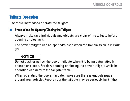
tailgate hits or closes on their heads. Be especially cautious if children are around.n Power Tailgate ButtonTo open or close the power tailgate,press the power tailgate button for about one second.If you press the button again while the power tailgate is moving, the power tailgate will stop and reverse direction.n Power Tailgate Outer HandleAutomatic OperationIf you press and hold the outer handle of the tailgate for no longer than one second, the tailgate opens automatically.Manual OperationTo open the tailgate manually, press the outer handle for more than onesecond.VEHICLE CONTROLSn Programmable Tailgate PositionYou can set the maximum opening of the tailgate to suit your needs.1.Manually adjust the tailgate to your desired position.2.Press and hold the tailgate inner button until you hear one long and two short beeps.n Power Tailgate Inner ButtonPress the button on the tailgate to close the power tailgate.If you press the button again while the power tailgate is moving, the power tailgate will stop and reverses direction.n Hands-Free Access Power Tailgate *1Use a forward and back kicking motion under the center of the rear bumper to open or close the power tailgate while carrying the smart entry remote. Some exterior lights flash twice and a beep sounds once, then the tailgate begins to move.Note: This function will not operate if you don't have the smart entry remote on you. Please make sure you have the smart entry remote on you.During rain or in other instances when the vehicle becomes wet, the sensor may not properly detect your foot motion.The duration of the kicking motion should be approximately one second.*1 - If equipped VEHICLE CONTROLS。
E阀英文资料

the baker model differential displacing valve is a hydraulicalty operated completion valve designed to allow an operator to flange up the well贝克E型差动循环阀是靠液压操作、有计划的允许操作工给井装上法兰的阀perform an annulus test on a packer and displace the tubing fluid, Iis capable of holding a maximum of 10000psi annulus pressure while testing the packer在封隔器上方完成一个环形空间试验和循环出管柱流体,当测试封隔器的时候,它最大能承受10000PSI的环空压力when run below a Baker Hydrostatic Single-string or Dual Packer,this valve may be used to replace the Hydro-Trip Pressure Sub provided the tubing will not have to be pressured internally at any time prior to opening the valve当用在一个贝克的液压的双管或单管封隔器以下时,这个阀可以用来代替水力活塞压力接头,倘若在任何时间打开阀之前这个接头不承受内压。
the model valve is run in the well on the tubing string above or below a packer,after performing the packer test on the annulus,a preselected differential tubing pressure forces the outer shifting sleeve 11 down shearing the shear screw(headless brass screw 9)allowing displacement of fluid in either direction贝克E型差动循环阀用在井眼的油管柱之上或封隔器之下,封隔器坐封后,一个预先选择好的管柱压力施加在外滑套上(序11)向下剪切这个剪切螺钉(无头的黄铜螺钉序9)使流体在任一方向循环。
- 1、下载文档前请自行甄别文档内容的完整性,平台不提供额外的编辑、内容补充、找答案等附加服务。
- 2、"仅部分预览"的文档,不可在线预览部分如存在完整性等问题,可反馈申请退款(可完整预览的文档不适用该条件!)。
- 3、如文档侵犯您的权益,请联系客服反馈,我们会尽快为您处理(人工客服工作时间:9:00-18:30)。
✸
Packer OD mm 91.2 139.7
✸
Lower Sealing Bore ID in. mm 2.390 60.7 3.875 98.4 3.625 92.0
7-5/8 7-3/4
193.7 196.9
6.000 5.875 6.000
✸
152.4 149.2 152.4✸Biblioteka 4.000101.6
Tools Representative. NOTE: Contact your local Baker Oil Tools Representative for information regarding pressure and temperature ratings, and elastomer availability.
Baker Oil Tools
PERMANENT PACKER SYSTEMS
MODEL FB-3™ HIGH PRESSURE RETAINER PRODUCTION PACKER
Product Family No. H41350 thus limit the transmission of compression into the packer. The seal bore sizes have been optimized to be compatible with large diameter TCP guns, allowing removal after firing. PERFORM Packer Performance Envelopes are available for all sizes of the Model FB-3 Packers (see page 12).
✸ Contact your local Baker Oil Tools Representative for packer OD. q When proposed for use in other than the casing weight range shown, contact your Baker Oil
FEATURES/BENEFITS
• Packers rated for differential pressures up to 15,000 psi dependent on size • Largest possible opening through packer for high pressure applications • Uniquely designed sealing element eliminates need for wire mesh in extreme applications • One piece body with premium thread down for Seal Bore Extension enhances reliability • Standard slips will grip V-150 casing • May be set with standard wireline or drill pipe setting tools
DESCRIPTION/APPLICATION
The Baker Model FB-3 High Pressure Retainer Production Packer is designed for deep well tests where high hydrostatic annulus pressures may be encountered. The most common use of this packer is in high pressure DST completions, where possible evacuation of tubing fluids during perforating induce extreme loads on packers. These packers differ from the conventional FB-1 Packers in that they have non-sealing bores. Seal Bore Extensions attached below the packer will function as the tubing to packer sealing device, while the packer effects the casing seal and supports the induced loads. In cases of extreme annulus pressure from above, the seal assembly may be spaced-out to prevent contact with the locating shoulder, and
SPECIFICATION GUIDE
Casing OD in. 5 7 mm 127.0 177.8 Weight lb/ft 26.7 42.7 32-41 26 51.2 -55.3 47.1 39 46.1 Size q 22-23 82-38 83-36 83-40 87-40 85-40 87-40 89-40 in. 3.594 5.500