PS2561AL2-1-A中文资料
PA2561L1-1(NEC)光耦规格书
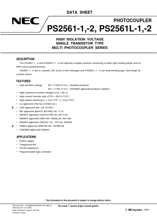
DATA SHEETThe information in this document is subject to change without notice.©1992Document No. P12989EJ4V0DS00 (4th edition)(Previous No. LC-2225)Date Published August 1997 NS Printed in JapanPHOTOCOUPLERPS2561-1,-2, PS2561L-1,-2HIGH ISOLATION VOLTAGE SINGLE TRANSISTOR TYPE MULTI PHOTOCOUPLER SERIESThe mark shows major revised points.DESCRIPTIONThe PS2561-1, -2 and PS2561L-1, -2 are optically coupled isolators containing a GaAs light emitting diode and an NPN silicon phototransistor.PS2561-1, -2 are in a plastic DIP (Dual In-line Package) and PS2561L-1, -2 are lead bending type (Gull-wing) for surface mount.FEATURES•High isolation voltageBV = 5 000 Vr.m.s.: standard productsBV = 3 750 Vr.m.s.: VDE0884 approved products (Option)•High collector to emitter voltage (V CEO = 80 V)•High current transfer ratio (CTR = 200 % TYP.)•High-speed switching (t r = 3 µs TYP., t f = 5 µs TYP.)•UL approved (File No. E72422 (S) )•CSA approved (No. CA 101391)•BSI approved (BS415, BS7002) No. 7112•SEMKO approved (SS4410165) No. 9317144•NEMKO approved (NEK-HD 195S6) No. A21409•DEMKO approved (Section 101, 137) No. 300535•FIMKO approved (E69-89) No. 167265-08•VDE0884 approved (Option)APPLICATIONS•Power supply •Telephone/FAX.•FA/OA equipment•Programmable logic controller2PACKAGE DIMENSIONS (in millimeters)DIP Type5.1 MAX.6.53.8M A X .4.55M A X .2.8M I N .0.652.547.620.50 ± 0.100.25M4312PS2561-1 (New Package)10.2 MAX.1.25±0.156.53.8M A X .4.55M A X .2.8M I N .0.652.547.620.50 ± 0.100.25M871265340 to 15˚PS2561-20 to 15˚PS2561-14.6 ± 0.351.25±0.156.53.8M A X .4.55M A X .2.8M I N .0.650.50 ± 0.100.25M0 to 15˚7.622.5443121.25±0.15PS2561L1-15.1 MAX.6.53.8M A X .4.25M A X .2.8M I N .0.352.547.620.50 ± 0.100.25M0 to 15˚43121.25±0.1510.161. Anode 2. Cathode 3. Emitter 4. Collector 1, 3. Anode 2, 4. Cathode 5, 7. Emitter 6, 8. Collector1. Anode2. Cathode3. Emitter4. Collector 1. Anode 2. Cathode 3. Emitter 4. Collector Caution New package 1ch only3Lead Bending Type5.1 MAX.6.53.8M A X .2.547.620.25M4312PS2561L-1 (New Package)10.2 MAX.1.25±0.156.53.8M A X .2.547.6287126534PS2561L-2PS2561L-14.6 ± 0.351.25±0.156.53.8M A X .0.25M7.622.5443121.25±0.150.05 t o 0.29.60 ± 0.40.90 ± 0.250.05 t o 0.29.60 ± 0.40.90 ± 0.250.25M0.05 t o 0.29.60 ± 0.40.90 ± 0.255.1 MAX.6.53.8M A X .2.547.620.25MPS2561L2-143121.25±0.150.05 t o 0.210.160.9 ± 0.2512.0 MAX.1. Anode2. Cathode3. Emitter4. Collector1, 3. Anode 2, 4. Cathode 5, 7. Emitter 6, 8. Collector 1. Anode 2. Cathode 3. Emitter 4. Collector 1. Anode 2. Cathode 3. Emitter 4. Collector Caution New package 1ch only4ORDERING INFORMATIONPart NumberPackageSafety Standard ApprovalApplication partnumber *1PS2561-1PS2561L-1PS2561L1-1PS2561L2-14-pin DIP4-pin DIP (lead bending surface mount)4-pin DIP (for long distance)4-pin DIP (for long distance surfacemount)Standard products PS2561-1PS2561-2PS2561L-28-pin DIP8-pin DIP (lead bending surface mount)PS2561-2PS2561-1-V PS2561L-1-V PS2561L1-1-V PS2561L2-1-V 4-pin DIP4-pin DIP (lead bending surface mount)4-pin DIP (for long distance)4-pin DIP (for long distance surfacemount)VDE0884 approved products (Option)PS2561-1PS2561-2-V PS2561L-2-V8-pin DIP8-pin DIP (lead bending surface mount)PS2561-2*1 As applying to Safety Standard, following part number should be used.ABSOLUTE MAXIMUM RATINGS (T A = 25 °C, unless otherwise specified)ParameterSymbolRatingsUnitPS2561-1,PS2561L-1PS2561-2,PS2561L-2DiodeReverse Voltage V R 6V Forward Current (DC)I F80mAPower Dissipation Derating ∆P D /°C 1.5 1.2mW/°C Power Dissipation P D 150120mW/ch Peak Forward Current*1I FP 1A TransistorCollector to Emitter Voltage V CEO 80V Emitter to Collector Voltage V ECO 7V Collector CurrentI C50mA/chPower Dissipation Derating ∆P C /°C 1.5 1.2mW/°C Power DissipationP C 150120mW/ch Isolation Voltage*2BV5 0003 750*3Vr.m.s.Operating Ambient Temperature T A –55 to +100°C Storage TemperatureT stg–55 to +150°C*1PW = 100 µs, Duty Cycle = 1 %*2AC voltage for 1 minute at T A = 25 °C, RH = 60 % between input and output *3VDE0884 approved products (Option)•UL approved •CSA approved •BSI approved•NEMKO approved •DEMKO approved •SEMKO approved•FIMKO approved5ELECTRICAL CHARACTERISTICS (T A = 25 °C)ParameterSymbol Conditions MIN.TYP.MAX.Unit DiodeForward Voltage V F I F = 10 mA 1.171.4VReverse Current I R V R = 5 V5µA Terminal CapacitanceC t V = 0 V, f = 1.0 MHz 50pFTransistorCollector to Emitter Dark CurrentI CEOV CE = 80 V, I F = 0 mA100nACoupled Current Transfer Ratio *1CTR I F = 5 mA, V CE = 5 V 80200400%Collector Saturation VoltageV CE (sat)I F = 10 mA, I C = 2 mA0.3V Isolation Resistance R I-O V I-O = 1.0 kV 1011ΩIsolation Capacitance C I-O V = 0 V, f = 1.0 MHz0.5pFRise Time *2t r V CC = 10 V, I C = 2 mA, R L = 100 Ω3µsFall Time*2t f5*1CTR rank (only PS2561-1, PS2561L-1)*2Test circuit for switching timeL: 200 to 400 (%)M : 80 to 240 (%)D : 100 to 300 (%)H : 80 to 160 (%)W : 130 to 260 (%)V CCV OUTR L = 100 Ω50 ΩI F µPulse InputPW = 100 sDuty Cycle = 1/106TYPICAL CHARACTERISTICS (T A = 25 °C, unless otherwise specified)150100500255075100125150 1.5 mW/˚C1.2 mW/˚C15010050255075100125150010 0001001 000100101755025–25–50V CE = 80 V10 1.00.80.60.40.20510.50.110 m A401.5 mW/˚C1.2 mW/˚C20 m A 50 m A 2 m AI F = 1 mA5 m A 70260504030201004681020 m A I F = 5 mA10m A 50 m A 40 V 24 V 10 V 5 VPS2561-1PS2561L-1PS2561-2PS2561L-2PS2561-1PS2561L-1PS2561-2PS2561L-2100 1.51.41.31.21.11.00.90.80.75010510.50.10 ˚C –25 ˚C –55 ˚C+60 ˚C +25 ˚CT A = +100 ˚CD i o d e P o w e r D i s s i p a t i o n P D (m W )T r a n s i s t o r P o w e r D i s s i p a t i o n P C (m W )Ambient Temperature T A (˚C)F o r w a r d C u r r e n t I F (m A )Forward Voltage V F (V)C o l l e c t o r C u r r e n t I C (m A )Collector to Emitter Voltage V CE (V)C o l l e c t o r t o E m i t t e rD a r k C u r r e n t I CE O (n A )Collector Saturation Voltage V CE(sat) (V)Ambient Temperature T A (˚C)Ambient Temperature T A (˚C)DIODE POWER DISSIPATION vs.AMBIENT TEMPERATURETRANSISTOR POWER DISSIPATION vs. AMBIENT TEMPERATUREFORWARD CURRENT vs.FORWARD VOLTAGECOLLECTOR CURRENT vs.COLLECTOR TO EMITTER VOLTAGECOLLECTOR TO EMITTER DARKCURRENT vs. AMBIENT TEMPERATURECOLLECTOR CURRENT vs.COLLECTOR SATURATION VOLTAGEC o l l e c t o r C u r r e n t I C (m A )7PS2561-1,-2,PS2561L-1,-21.2–501.00.80.60.40.20–252550751004504003503002502001501005000.050.10.5151050501010.110 k5 k 1 k50010050101 000100101100 k50 k 10 k5 k 1 k5001000–5–10–15–200.5125102050100200500I C = 2 mA,V CC = 10 V,CTR = 290 %t f t rt dt sI F = 5 mA,V CC = 5 V,CTR = 290 %t st dt rt fI F = 5 mA,V CE = 5 V100 Ω300 ΩR L = 1 k ΩI F = 5 mA T A = 25 ˚CI F = 5 mA T A = 60 ˚C 1.21.00.80.60.40.2102103104105Normalized to 1.0at T A = 25 ˚C,I F = 5 mA, V CE = 5 VForward Current I F (mA)Ambient Temperature T A (˚C)Load Resistance R L (Ω)Frequency f (kHz)N o r m a l i z e d C u r r e n t T r a n s f e r R a t i o C T RC u r r e n t T r a n s f e r R a t i o C T R (%)N o r m a l i z e d G a i n G VLoad Resistance R L (Ω)S w i t c h i n g T i m e t ( s )µNORMALIZED CURRENT TRANSFER RATIO vs. AMBIENT TEMPERATURECURRENT TRANSFER RATIO vs.FORWARD CURRENTSWITCHING TIME vs.LOAD RESISTANCESWITCHING TIME vs.LOAD RESISTANCEFREQUENCY RESPONSELONG TIME CTR DEGRADATIONS w i t c h i n g T i m e t ( s )µTYP.Time (Hr)C T R (R e l a t i v e V a l u e )8TAPING SPECIFICATIONS (in millimeters)Taping DirectionPS2561L-1-E3PS2561L-1-F3PS2561L-1-E4PS2561L-1-F4Outline and Dimensions (Tape)1.55±0.12.0±0.14.0±0.11.55±0.11.75±0.14.3±0.210.3±0.10.37.5±0.116.0±0.35.6±0.18.0±0.1Outline and Dimensions (Reel)Packing: PS2561L-1-E3, E4 1 000 pcs/reel2.0±0.5R 1.013.0±0.5φ21.0±0.8φ16.4+2.0–0.0P S 2561L -1-E 3, E 4: 250P S 2561L -1-F 3, F 4: 330φ80.0±5.0φφPS2561L-1-F3, F4 2 000 pcs/reel9Taping DirectionPS2561L-2-E3PS2561L-2-E4Outline and Dimensions (Tape)1.55±0.12.0±0.14.0±0.11.55±0.11.75±0.14.3±0.210.3±0.10.37.5±0.116.0±0.310.4±0.112.0±0.1Outline and Dimensions (Reel)Packing: 1 000 pcs/reel16.4+2.0–0.080.0±5.0φ330φ2.0±0.5R 1.013.0±0.5φ21.0±0.8φ10RECOMMENDED SOLDERING CONDITIONS(1) Infrared reflow soldering • Peak reflow temperature235 °C (package surface temperature)• Time of temperature higher than 210 °C 30 seconds or less • Number of reflows Three• FluxRosin flux containing small amount of chlorine (The flux with a maximum chlorine content of 0.2 Wt % is recommended.)60 to 90 s (preheating)210 ˚C120 to 160 ˚CP a c k a g e S u r f a c e T e m p e r a t u r e T (˚C )Time (s)(heating)to 10 sto 30 s235 ˚C (peak temperature)Recommended Temperature Profile of Infrared ReflowPeak temperature 235 ˚C or belowCaution Please avoid to removed the residual flux by water after the first reflow processes.(2) Dip soldering • Temperature 260 °C or below (molten solder temperature)• Time10 seconds or less • Number of times One• FluxRosin flux containing small amount of chlorine (The flux with a maximum chlorine content of 0.2 Wt % is recommended.)11SPECIFICATION OF VDE MARKS LICENSE DOCUMENT (VDE0884)ParameterSymbolSpeckUnitApplication classification (DIN VDE 0109)for rated line voltages ≤ 300 Vr.m.s.for rated line voltages ≤ 600 Vr.m.s.IV III Climatic test class (DIN IEC 68 Teil 1/09.80)55/100/21Dielectric strength maximum operating isolation voltageTest voltage (partial discharge test procedure a for type test and random test)U pr = 1.2 × U IORM , P d < 5 pCU IORM U pr 8901 068V peak V peakTest voltage (partial discharge test procedure b for random test)U pr = 1.6 × U IORM , P d < 5 pC U pr 1 424V peakHighest permissible overvoltage U TR 6 000V peakDegree of pollution (DIN VDE 0109)2Clearance distance > 7.0mm Creepage distance> 7.0mmComparative tracking index (DIN IEC 112/VDE 0303 part 1)CTI 175Material group (DIN VDE 0109)III a Storage temperature range T stg –55 to +150°C Operating temperature rangeT A –55 to +100°C Isolation resistance, minimum value V IO = 500 V dc at T A = 25 °CV IO = 500 V dc at T A MAX. at least 100 °CRis MIN.Ris MIN.10121011ΩΩSafety maximum ratings (maximum permissible in case of fault, see thermal derating curve)Package temperatureCurrent (input current I F , Psi = 0)Power (output or total power dissipation)Isolation resistanceV IO = 500 V dc at T A = 175 °C (Tsi)Tsi Isi Psi Ris MIN.175********9°C mA mW ΩCAUTIONWithin this device there exists GaAs (Gallium Arsenide) material which is aharmful substance if ingested. Please do not under any circumstances break thehermetic seal.No part of this document may be copied or reproduced in any form or by any means without the prior written consent of NEC Corporation. NEC Corporation assumes no responsibility for any errors which may appear in this document.NEC Corporation does not assume any liability for infringement of patents, copyrights or other intellectual property rights of third parties by or arising from use of a device described herein or any other liability arising from use of such device. No license, either express, implied or otherwise, is granted under any patents, copyrights or other intellectual property rights of NEC Corporation or others.While NEC Corporation has been making continuous effort to enhance the reliability of its semiconductor devices, the possibility of defects cannot be eliminated entirely. To minimize risks of damage or injury to persons or property arising from a defect in an NEC semiconductor device, customers must incorporate sufficient safety measures in its design, such as redundancy, fire-containment, and anti-failure features.NEC devices are classified into the following three quality grades:"Standard", "Special", and "Specific". The Specific quality grade applies only to devices developed based on a customer designated "quality assurance program" for a specific application. The recommended applications of a device depend on its quality grade, as indicated below. Customers must check the quality grade of each device before using it in a particular application.Standard: Computers, office equipment, communications equipment, test and measurement equipment, audio and visual equipment, home electronic appliances, machine tools, personal electronicequipment and industrial robotsSpecial: Transportation equipment (automobiles, trains, ships, etc.), traffic control systems, anti-disaster systems, anti-crime systems, safety equipment and medical equipment (not specifically designedfor life support)Specific: Aircrafts, aerospace equipment, submersible repeaters, nuclear reactor control systems, life support systems or medical equipment for life support, etc.The quality grade of NEC devices is "Standard" unless otherwise specified in NEC's Data Sheets or Data Books. If customers intend to use NEC devices for applications other than those specified for Standard quality grade, they should contact an NEC sales representative in advance.Anti-radioactive design is not implemented in this product.M4 96. 5。
PS2501-1-A中文资料
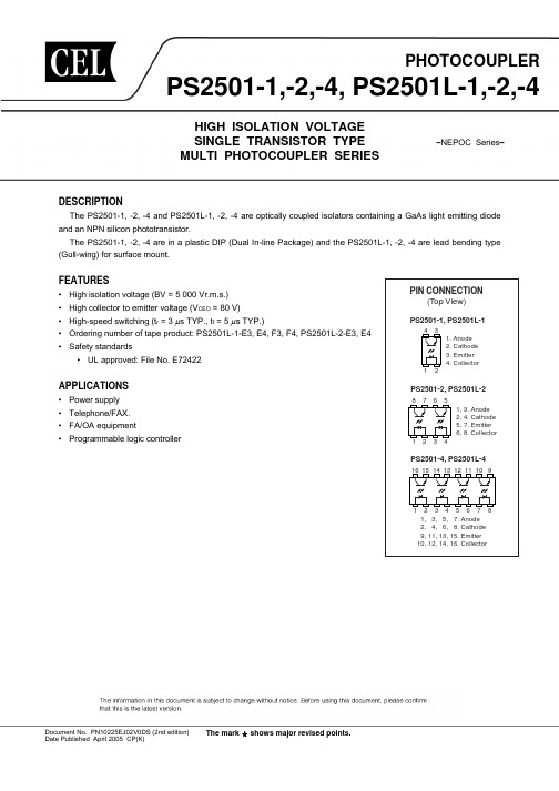
12
PS2501-2, PS2501L-2
8765 1234
1, 3. Anode 2, 4. Cathode 5, 7. Emitter 6, 8. Collector
PS2501-4, PS2501L-4
0.50±0.10
2.54
0.25 M
0
to 15˚ 0.25
+0.1 –0.05
2
Data Sheet PN10225EJ02V0DS
元器件交易网
Lead Bending Type (New package) PS2501L-1
4.6±0.35
PS2501-1,-2,-4, PS2501L-1,-2,-4
• UL approved: File No. E72422
APPLICATIONS
• Power supply • Telephone/FAX. • FA/OA equipment • Programmable logic controller
PIN CONNECTION (Top View)
PS2501-1, PS2501L-1
PS2501L-4
19.8±0.5
6.5±0.5
6.5±0.5
+0.1 –0.05
+0.1 –0.05
+0.1 –0.05
+0.1 –0.05
0.1
0.25
3.5±0.3
0.1
0.25
3.5±0.3
1.25±0.15 0.25 M 2.54
0.9±0.25 9.60±0.4 0.15
TCL 24英寸LED二合一电源板规格书说明书

TCL集团多媒体电子事业本部 文件编号:QP7.3-F01-2006.1 研发中心第 1 页 共 1 页新规格物料■认可书/□取消认可书编制日期:Power Supply Specification(电源规格书)Customer (客户):TCL 王牌Part No. (机种型号):PLE50P-2ERevision (版本): REV 1.0Description(描述1): 24 寸LED LIPSDescription(描述2): LED 55V*120mA*2承认鉴章后请寄回承认书正本一份Please return to us one original of “SPECIFICATION FOR APPROVAL” withyour approved signatures.APPROVED SHEET(承认书)核准人 APPROVED BY:日期 DATE:盖章鉴署 CHOP & SIGNATURES:惠州TCL王牌高频电子有限公司地址:广东省惠州市仲恺高新技术开发区华宇路75号,邮编516006TEL:+86-752-2096984DATE PREPARED CHECKED APPROVED7.1. PCB Dimension: 150mm(L) * 118mm(W) * 15mm(H))7.2. Dimension with soleplate: NONE8. WEIGHT重量9. Pin Connection 连接器脚位定义2PIN-CN1: pitch 3.96mm Connection and FunctionConnection Function Item Pin1 AC-L AC INPUT LINEPLE50P.BZXPLE50PS C H S C H112.5V2A廖静2012-01-09A C I N P U T符运豪张军胜2012-01-092012-01-09CN1F1CX1C414C419C422C403C411C Y 3C412C4164312LF12134LF2R100R101R102R434R443R447R444R445R446R407R406R422R427R428R429R430R425R426R103CE1C424QW1PC1-BPC1-AD401D402DS2L400C405C404A_1R KIC3D400C415C402R414R403R402VDD GATESENSE GND RIFB 123456D101D103D104D102R449FB401RN115VIN 16VCC 1COMP 2EN 5OSC7BOSC 3DBRT 6ISET8LED49LED310LED211LED112OVP 4GND 13ISENSE 14GATE IC5MP3394L601INDD600Q603C 601C 602C 603R 601R 617R 618C 616R 619R 620C 613C 614C 615C 604C 605R 602R 603C 606R 604R 605R 606C 607R 608C 608R 609R 607C 612R 616R 621R 622R 623R 624123456Z 401R 431D 403R 432R 441R 433Q 402D 404R 442R 439Q 401R 438C 417R 440C 418CE2C 420L 602INDD 405R 625C 430C 429C Y 1C Y 2123TS1-A456TS1-B 87TS1-C C 426C 40787654321SWCSWETCGNDCIIVCCIPKDRC I C 4R 436R 43512L 401D 406C 425R421C 406R 450R 451R 453R 452C 421C 413Q 404483Q 403R 408C 620C 619C 618C 617C 623R 423R 612R 615C 610R 610R 611C 428D 601R 437R 401R 627R 628SGNDHV Q1-SQ1-G+12VB+12VT+12V A LED+L E D 1-L E D 2-L E D 3-L E D 4-B L -O NVCCVCC VCC1LED1-LED2-LED+LED3-LED4-DIMVCC1+3_3V+12V BIC1-3-TC+12V B+12VA +12V B+12V P S .O N+12V+3_3V DIM36贴片电容102/50V +/-10%0805/X7R PCS2三新国巨风华高科B C425,C612 37贴片电容102/100V +/-10%0805/X7R PCS2三新国巨风华高科B C618,C620 38贴片电容103/50V +/-10%0805/X7R PCS1三新国巨风华高科B C41939贴片电容104/50V ±10%0805/X7R PCS8三新国巨风华高科BC411,C606,C608,C406,C413,C421,C426,C41840贴片电容104/100V +/-10%0805/X7R PCS2三新国巨风华高科BC613,C61541贴片电容334/50V+/-10%0805/X7R PCS1三新国巨风华高科B C41742贴片电容471/50V+/-10%0805/X7R PCS1三新国巨风华高科B C42243贴片电容474/25V+/-10%0805/X7R PCS2三新国巨风华高科B C604,C60544贴片电容105/50V +/-10%1206/X7R PCS2三新国巨风华高科B C429,C43045贴片电容102/500V +/-10%1206/X7R PCS1三新国巨风华高科B C40346贴片电容101/100V+/-5%0805/NPO PCS1三新国巨风华高科B C61047IC MC34063A SOP-8 HTC PCS1HTC UTC Diodes B IC448IC LD7536R SOT-26 Leadtrend PCS1Leadtrend A IC149IC MP3394 SOIC16PCS1MPS A IC550IC AZ431AZ-AE1 TO-92 BCD PCS1BCD B IC351贴片二极管BAS16H 215mA/100V SOD-123F PCS4NXP先科B D401,D403,D405,D404 52贴片三极管NPN PMBT2222A 600mA/40V SOT-23PCS1NXP先科B Q40453贴片MOS2N7002 300mA/60V SOT-23 NXP PCS2NXP先科B Q401,Q40254MOS管AOD417 P-Channel MOSFET -25A/-30V TO-252 34mΩPCS1AOS B Q40355N-MOS AOD478 11A/100V T0-252PCS1AOS B Q60356N-MOS TK6A60D 6A/600V TO-220F 东芝PCS1东芝华微A QW157快恢复二极管FR104 1A/400V DO-41PCS1沂光佳讯固得D40258快恢复二极管FR207 2A/1000V DO-15 沂光PCS1沂光佳讯固得B D40059整流二极管RL255 2.5A/600V SDO-15 沂光PCS4沂光佳讯固得B D101,D102,D103,D104 60肖特基二极管SB140 1A/40V DO-41 沂光PCS1沂光佳讯固得B D40661肖特基二极管SB260 2A/60V DO-15 沂光PCS2沂光佳讯固得B D600,D60162肖特基二极管MBR20100CTP 20A/100V ITO-220S DIODES PCS1DIODES A DS263光耦PS2561AL1-1(Dip-4) NEC PCS1NEC A PC164金属氧化膜电阻3WS 82KΩ+/-5% T PCS1百亨恒辉B R43465绕线无感电阻NKN2W 0.43Ω ±5% T 百亨PCS1百亨恒辉B R40366热敏电阻MF72-3D11 3Ω±20% 5A 内弯脚 时恒PCS1时恒A RN167电解电容ZP 22uF/100V ±20% 8*11.5 105℃ 275mA 东阳光PCS2东阳光华威A C614,C62368电解电容ZP 470uF/10V ±20% 8*11.5*5 105℃ 东阳光PCS1东阳光华威A C40169电解电容ZP 220uF/25V ±20% 8*11.5*5 105℃ 东阳光PCS2东阳光华威A C405,C60370电解电容ZP 22uF50V ±20% 5×11*5 105℃ 东阳光PCS1东阳光华威A C42471电解电容ZP 1000uF/25V ±20% 12.5*25*5 105℃ 东阳光PCS2东阳光华威A C402,C404第 2 页,共 3 页第 3 页,共 3 页。
PS2566L-1-V-E4-A中文资料
0.50±0.10 0.25 M
2.54
Caution New package 1-ch only
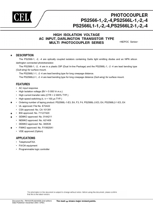
DIP Type
PS2566-1
4.6±0.5 4
TOP VIEW
3 1. Anode, Cathode 2. Cathode, Anode 3. Emitter 4. Collector
3.3±0.5 4.15±0.4
PS2566-2
9.7±0.5 8 7
TOP VIEW
6 5 1, 3. Anode, Cathode 2, 4. Cathode, Anode 5, 7. Emitter 6, 8. Collector
6.5±0.5
6.5±0.5
1
2 7.62
1
2
3 4 7.62
3.3±0.5 4.15±0.4
3.5±0.3
PS2566L2-1
4.6±0.5 4 3 1. Anode, Cathode 2. Cathode, Anode 3. Emitter 4. Collector 1 2 10.16
0.25–0.05
2
+0.1
PS2566L2-2 TOP VIEW
9.7±0.5 8 7
TOP VIEW
6 5 1, 3. Anode, Cathode 2, 4. Cathode, Anode 5, 7. Emitter 6, 8. Collector
The mark shows major revised points.
元器件交易网
PS2566-1,-2,-4,PS2566L-1,-2,-4,PS2566L1-1,-2,-4,PS2566L2-1,-2,-4
CXA2581中文资料
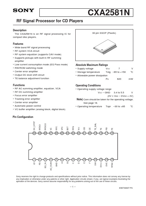
5 GND
I GND.
6A
I A signal input.
7B
I B signal input.
8C
I C signal input.
9D
I D signal input.
10 E
I E signal input.
11 F
I F signal input.
12 SW
I Mode switching signal input.
F 10 E 11
VC RW/ROM
DVC
VOFST DVC RW/ROM
VC
RW/ROM
VC gm
VOFST
DVCC
gm VOFST VC
RW/ROM
DVCC 29 RFDCI 28 RFDCO
DVCC 17 FEI 16 FE
19 TE_BAL RW/ROM
18 TE
SW 12 PD 2 LD 1
LD PD EQ_IN AC_SUM GND
A B C D E F SW DVCC DVC RFAC
Sony reserves the right to change products and specifications without prior notice. This information does not convey any license by any implication or otherwise under any patents or other right. Application circuits shown, if any, are typical examples illustrating the operation of the devices. Sony cannot assume responsibility for any problems arising out of the use of these circuits.
光耦器件选型列表

高速,转换时间:0.5us
SHARP 电流转换率 50%-400%@5mA 50%-400%@5mA 50%-600%@5mA [Min] 1000%@1mA [Min] 20%@1mA [Min] 20%@1mA [Min] 50%@5mA [Min] 80%@5mA [Min] 80%@5mA [Min] 80%@5mA NEC 电流转换率 转换率范围:80%-600%@5mA, 详见PDF 转换率范围:80%-600%@5mA, 详见PDF 转换率范围:80%-600%@5mA, 详见PDF 转换率范围:80%-400%@5mA, 详见PDF 转换率范围:50%-300%@5mA, 详见PDF 转换率范围:50%-400%@5mA, 详见PDF 转换率范围:50%-300%@5mA, 详见PDF 转换率范围:80%-600%@5mA, 详见PDF 转换率范围:80%-600%@5mA, 详见PDF 转换率范围:80%-600%@5mA, 详见PDF AVAGO 电流转换率 [Min] 0.25%@10mA [Min] 0.36%@10mA 其它描述 高速,10MBd 其它描述 其它描述
HCPL-4504 HCPL-4506
1 1
8mA 15mA
20V -
3750Vrms 3750Vrms
FAIRCHILD 最大 电流输出 100mA 100mA 100mA 100mA 150mA 150mA 150mA 2mA / 100mA 100mA 8mA 8mA 50mA 60mA 60mA 最大 电压输出 30V 30V 30V 30V 30V 30V 30V 20V 20V 7V 7V / 18V 隔离 电压 2500Vrms 7500Vrms 7500Vrms 7500Vrms 5300Vrms 多种 5300Vrms 多种 7500Vrms 2500Vrms 2500Vrms 2500Vrms 2500Vrms 2500Vrms
TSL2561传感器中文资料
TSL2561是光-数字转换器,它将光强转换成数字信号输出,具有直接I2C接口或者SMBus接口。
每个设备都连接一个带宽的光敏二极管和在单独CMOS集成电路上的一个红外响应的光敏二极管,这个集成电路具有提供20bit动态范围的近-适光响应的能力。
两个集成的ADCs将光敏电流转换成一个数字输出,这个数字输出表示测量每一个通道的发光。
这个数字输出可以是一个微处理器的输入。
在这个微处理器里亮度(周围光的水平)使用试验化公式来得到。
TSL2560设备允许SNBTSL256x是TAOS公司推出的一种高速、低功耗、宽量程、可编程灵活配置的光强传感器芯片。
本文简要介绍了TSL256x的基本特点、引脚功能、内部结构和工作原理,给出了TSL2561的实用电路、软件设计流程连同核心程式。
关键词光强传感器 TSL256x I2C总线积分式A/D转换器1TSL256x简介TSL2560和TSL2561是TAOS公司推出的一种高速、低功耗、宽量程、可编程灵活配置的光强度数字转换芯片。
该芯片可广泛应用于各类显示屏的监控,目的是在多变的光照条件下,使得显示屏提供最好的显示亮度并尽可能降低电源功耗;还能够用于街道光照控制、安全照明等众多场合。
该芯片的主要特点如下:◇可编程配置许可的光强度上下阈值,当实际光照度超过该阈值时给出中断信号;◇数字输出符合标准的SMBus(TSL2560)和I2C(TSL2561)总线协议;◇模拟增益和数字输出时间可编程控制;◇1.25 mm×1.75 mm超小封装,在低功耗模式下,功耗仅为0.75 mW;◇自动抑制50 Hz/60 Hz的光照波动。
2TSL256x的引脚功能TSL256x有2种封装形式: 6LEAD CHIPSCALE和6LEAD TMB。
封装形式不同,相应的光照度计算公式也不同。
图1为这两种封装形式的引脚分布图。
图1TSL256x封装各引脚的功能如下:脚1和脚3:分别是电源引脚和信号地。
安森美(5-12V)20W

R6
C5 510K Z1 25V C6 1nF 4.7uF C7
2.4K R9A/B 0.5W 1.8 Ohms x 2 9 R12
7
22uF C8 R11 D6 D7
R14
1K (12V) 240 (5V)
R17 R16 C12
20K NCP431 0.1 39K (12V) 10K (5V)
0 ohms MMSD 1N4937 2.0 4148A
1
DN05043/D For applications requiring 10 to 15 watts output, the NCP1126 version of the controller can be used which has exactly the same circuitry as the NCP1129, but with a different MOSFET. For optimum thermal characteristics, the printed circuit board should be laid out to include clad “pours” around pins 5 and 6 of the DIP8 package (MOSFET drain pins). Resistors 9A & B (paralleled) set the peak current limit point for the internal overcurrent protection circuit of U1 and can be adjusted for desired max output current (see NCP112x data sheet). For output voltages other than 5 volts, typical circuit changes include the transformer turns ratio for both the secondary and the primary aux winding (12V transformer design included below), the value of R17 in the output voltage sense divider, and selecting appropriate voltage ratings for output rectifier D8 and output capacitors C9A, B & C. Depending on the transformer aux winding characteristics, it may be necessary to change R11 to a higher value resistance value to adjust the nominal Vcc voltage. Z1 can be added as an option in the event that the compliance range of the Vcc over the output load range exceeds the OVP trip point on pin 1 of U1 (28 volts). Such a scenario would be the result of a transformer with high leakage inductance.
适配器安全件清单 (1)

厦门TDK有限公司
GB/T14472-1998
CQC03001004816
可替代
SE,SB
Success
Success
GB/T14472-1998
CQC02001001788
可替代
JN
嘉耐股份有限公司
东莞嘉耐电子有限公司
南京鸿科电子有限公司
GB/T14472-1998
CQC03001008419
Min.V-0,150℃
Sumitomo Bakelite
---
---
E41429
cp-j-8800
Min.V-0,150℃
HitachiChemical
---
---
E42956
绝缘胶带
1350F-1
Min.130℃
Minnesotamining&mfg co.,ltd
---
---
E17385
MY130#
GB4943-2001
CQC08001026788
4
CX1
X电容
HQX
0.1uF ,X2, ,Min.250V,100°C
台湾昱电实业股份有限公司
东莞企石新昱电容器厂
GB/T14472-1998
CQC03001003067
可替代
R.46
意大利阿可公司
ARCOTRONICS ITALIA S.P.A.
序号
位号
部件号
关键件名称
型号
规格/材料
生产者(制造商)
生产企业
认证标准
备注
1.
F1
保险丝
L3T
T8.0A,250V,KHC
TSL2561传感器中文资料

TSL2561是光-数字转换器,它将光强转换成数字信号输出,具有直接I2C接口或者SMBus接口。
每个设备都连接一个带宽的光敏二极管和在单独CMOS集成电路上的一个红外响应的光敏二极管,这个集成电路具有提供20bit动态范围的近-适光响应的能力。
两个集成的ADCs将光敏电流转换成一个数字输出,这个数字输出表示测量每一个通道的发光。
这个数字输出可以是一个微处理器的输入。
在这个微处理器里亮度(周围光的水平)使用试验化公式来得到。
TSL2560设备允许SNBTSL256x是TAOS公司推出的一种高速、低功耗、宽量程、可编程灵活配置的光强传感器芯片。
本文简要介绍了TSL256x的基本特点、引脚功能、内部结构和工作原理,给出了TSL2561的实用电路、软件设计流程连同核心程式。
关键词光强传感器 TSL256x I2C总线积分式A/D转换器1TSL256x简介TSL2560和TSL2561是TAOS公司推出的一种高速、低功耗、宽量程、可编程灵活配置的光强度数字转换芯片。
该芯片可广泛应用于各类显示屏的监控,目的是在多变的光照条件下,使得显示屏提供最好的显示亮度并尽可能降低电源功耗;还能够用于街道光照控制、安全照明等众多场合。
该芯片的主要特点如下:◇可编程配置许可的光强度上下阈值,当实际光照度超过该阈值时给出中断信号;◇数字输出符合标准的SMBus(TSL2560)和I2C(TSL2561)总线协议;◇模拟增益和数字输出时间可编程控制;◇1.25 mm×1.75 mm超小封装,在低功耗模式下,功耗仅为0.75 mW;◇自动抑制50 Hz/60 Hz的光照波动。
2TSL256x的引脚功能TSL256x有2种封装形式: 6LEAD CHIPSCALE和6LEAD TMB。
封装形式不同,相应的光照度计算公式也不同。
图1为这两种封装形式的引脚分布图。
图1TSL256x封装各引脚的功能如下:脚1和脚3:分别是电源引脚和信号地。
tsl2561 (2)
TSL2561IntroductionTSL2561是一种数字光传感器,能够测量环境中的光强度。
它采用了比较器、积分计数器和16位ADC等多种技术,可以实现高精度和广泛的测量范围。
TSL2561非常适合用于光照控制、照明系统和环境监测等领域。
Features•双通道光敏器件,包括一个可见光通道和一个红外通道•测量范围广泛,从0.1-40,000 LUX•16位ADC,能够提供高精度的测量结果•选择性增益和易制定的积分时间,以满足不同应用的需求•支持硬件和软件阈值比较器,可以方便地进行光强度门限检测•低功耗,工作电流仅为0.5 mA(typ)•小尺寸和表面贴装封装,方便集成到各种应用中InterfaceTSL2561使用标准的I2C接口进行通信。
它具有一个7位I2C设备地址,可以通过连接到不同的电平来选择不同的地址。
为了方便使用,TSL2561还提供了一个中断引脚,用于通知主控设备测量结果已经超过或低于预设的阈值。
Register MapTSL2561通过I2C访问其内部寄存器,进行配置和数据读取。
以下是一些重要的寄存器及其功能:•0x00 CONTROL: 用于配置工作模式和增益等相关设置。
可以通过写入不同的模式来选择不同的光强度范围和积分时间。
•0x01 TIMING: 包含了积分时间的设置,可以用于调整测量的精度和响应速度。
•0x12 DATA0: 可见光通道的原始光强度数据,低字节。
•0x13 DATA1: 可见光通道的原始光强度数据,高字节。
•0x14 DATA2: 红外通道的原始光强度数据,低字节。
•0x15 DATA3: 红外通道的原始光强度数据,高字节。
Example Usage以下是一个使用TSL2561进行光强度测量的示例代码:```python import smbus初始化I2C总线bus = smbus.SMBus(1) # 这里使用的是树莓派的I2C接口,根据实际情况修改TSL2561的I2C地址,默认为0x39TSL2561_ADDR = 0x39打开TSL2561传感器def tsl2561_power_on():bus.write_byte_data(TSL2561_ADDR, 0x00, 0x03)关闭TSL2561传感器def tsl2561_power_off():bus.write_byte_data(TSL2561_ADDR, 0x00, 0x00)读取光强度数据def read_lux(): # 设置积分时间为402msbus.write_byte_data(TSL2561_ADDR, 0x01, 0x02)# 等待一段时间,让传感器完成测量time.sleep(0.5)# 读取数据data0 = bus.read_byte_data(TSL2561_ADDR, 0x12) data1 = bus.read_byte_data(TSL2561_ADDR, 0x13) data2 = bus.read_byte_data(TSL2561_ADDR, 0x14) data3 = bus.read_byte_data(TSL2561_ADDR, 0x15)# 结合高字节和低字节计算光强度visible = (data1 << 8) | data0infrared = (data3 << 8) | data2# 计算光照强度(单位:lux)ratio = infrared / visibleif ratio < 0.5:lux = 0.0304 * visible - 0.062 * visible * (r atio ** 1.4)elif ratio < 0.61:lux = 0.0224 * visible - 0.031 * infraredelif ratio < 0.80:lux = 0.0128 * visible - 0.0153 * infrared elif ratio < 1.30:lux = 0.00146 * visible - 0.00112 * infrared else:lux = 0return lux主程序if name ==。
TSL2561传感器中文资料

TSL2561是光-数字转换器,它将光强转换成数字信号输出,具有直接I2C接口或者SMBus接口。
每个设备都连接一个带宽的光敏二极管和在单独CMOS集成电路上的一个红外响应的光敏二极管,这个集成电路具有提供20bit动态范围的近-适光响应的能力。
两个集成的ADCs将光敏电流转换成一个数字输出,这个数字输出表示测量每一个通道的发光。
这个数字输出可以是一个微处理器的输入。
在这个微处理器里亮度(周围光的水平)使用试验化公式来得到。
TSL2560设备允许SNBTSL256x是TAOS公司推出的一种高速、低功耗、宽量程、可编程灵活配置的光强传感器芯片。
本文简要介绍了TSL256x的基本特点、引脚功能、内部结构和工作原理,给出了TSL2561的实用电路、软件设计流程连同核心程式。
关键词光强传感器 TSL256x I2C总线积分式A/D转换器1TSL256x简介TSL2560和TSL2561是TAOS公司推出的一种高速、低功耗、宽量程、可编程灵活配置的光强度数字转换芯片。
该芯片可广泛应用于各类显示屏的监控,目的是在多变的光照条件下,使得显示屏提供最好的显示亮度并尽可能降低电源功耗;还能够用于街道光照控制、安全照明等众多场合。
该芯片的主要特点如下:◇可编程配置许可的光强度上下阈值,当实际光照度超过该阈值时给出中断信号;◇数字输出符合标准的SMBus(TSL2560)和I2C(TSL2561)总线协议;◇模拟增益和数字输出时间可编程控制;◇1.25 mm×1.75 mm超小封装,在低功耗模式下,功耗仅为0.75 mW;◇自动抑制50 Hz/60 Hz的光照波动。
2TSL256x的引脚功能TSL256x有2种封装形式: 6LEAD CHIPSCALE和6LEAD TMB。
封装形式不同,相应的光照度计算公式也不同。
图1为这两种封装形式的引脚分布图。
图1TSL256x封装各引脚的功能如下:脚1和脚3:分别是电源引脚和信号地。
- 1、下载文档前请自行甄别文档内容的完整性,平台不提供额外的编辑、内容补充、找答案等附加服务。
- 2、"仅部分预览"的文档,不可在线预览部分如存在完整性等问题,可反馈申请退款(可完整预览的文档不适用该条件!)。
- 3、如文档侵犯您的权益,请联系客服反馈,我们会尽快为您处理(人工客服工作时间:9:00-18:30)。
2003, 2008The mark <R> shows major revised points.The revised points can be easily searched by copying an "<R>" in the PDF file and specifying it in the "Find what:" field.DESCRIPTIONThe PS2561A-1 is an optically coupled isolator containing a G aAs light emitting diode and an NPN silicon phototransistor to realize an excellent cost performance.The PS2561A-1 is in a plastic DIP (Dual In-line Package) and the PS2561AL-1 is lead bending type (Gull-wing) for surface mount.The PS2561AL1-1 is lead bending L1 type and the PS2561AL2-1 is lead bending L2 type (Gull-wing).FEATURES• High isolation voltage (BV = 5 000 Vr.m.s.)• Ordering number of taping product: PS2561AL-1-E3, E4, F3, F4: PS2561AL2-1-E3, E4• Pb-Free product• Safety standards • UL approved: No. E72422 • CSA approved: No. CA 101391 • BSI approved: No. 7112, 7420 • SEMKO approved: No. 607784 • NEMKO approved: No. P0******* • DEMKO approved: No. 312032 • FIMKO approved: No. FI 22778• DIN EN60747-5-2 (VDE0884 Part2) approved: No. 40008862 (Option)APPLICATIONS• Power supply • Telephone/FAX. • FA/OA equipment• Programmable logic controller<R>DATA SHEETThe information in this document is subject to change without notice. Before using this document, pleaseconfirm that this is the latest version.Not all products and/or types are available in every country. Please check with an NEC Electronics sales representative for availability and additional information.Document No. PN10222EJ05V0DS (5th edition)Date Published September 2008 NS Printed in JapanPACKAGE DIMENSIONS (UNIT : mm)DistanceCreepage Type LongDIPLead Bending Type (Gull-Wing) Long Creepage Distance (Gull-Wing)2Data Sheet PN10222EJ05V0DSMARKING EXAMPLE<R>Data Sheet PN10222EJ05V0DS3ORDERING INFORMATIONPart Number Order Number Solder PlatingSpecification Packing Style Safety StandardApprovalApplication PartNumber *1PS2561A-1 PS2561A-1-A Pb-Free Magazine case 100 pcs Standard products PS2561A-1 PS2561AL-1 PS2561AL-1-A (UL,CSA,BSI,PS2561AL1-1 PS2561AL1-1-A NEMKO,DEMKO,PS2561AL2-1 PS2561AL2-1-A SEMKO,FIMKOPS2561AL-1-E3 PS2561AL-1-E3-A Embossed Tape 1 000 pcs/reel approved)PS2561AL-1-E4 PS2561AL-1-E4-APS2561AL2-1-E3 PS2561AL2-1-E3-A Embossed Tape 1 000 pcs/reelPS2561AL2-1-E4 PS2561AL2-1-E4-APS2561AL-1-F3 PS2561AL-1-F3-A Embossed Tape 2 000 pcs/reelPS2561AL-1-F4 PS2561AL-1-F4-APS2561A-1-V PS2561A-1-V-A Magazine case 100 pcs DIN EN60747-5-2PS2561AL-1-V PS2561AL-1-V-A (VDE0884Part2)PS2561AL1-1-V PS2561AL1-1-V-A Approved(option)PS2561AL2-1-V PS2561AL2-1-V-APS2561AL-1-V-E3 PS2561AL-1-V-E3-A Embossed Tape 1 000 pcs/reelPS2561AL-1-V-E4 PS2561AL-1-V-E4-APS2561AL2-1-V-E3 PS2561AL2-1-V-E3-A Embossed Tape 1 000 pcs/reelPS2561AL2-1-V-E4 PS2561AL2-1-V-E4-APS2561AL-1-V-F3 PS2561AL-1-V-F3-A Embossed Tape 2 000 pcs/reelPS2561AL-1-V-F4 PS2561AL-1-V-F4-A*1 For the application of the Safety Standard, following part number should be used.Data Sheet PN10222EJ05V0DS4ABSOLUTE MAXIMUM RATINGS (T A = 25°C, unless otherwise specified)Ratings UnitParameter SymbolVoltage V R 6 VDiode Reverse(DC) I F 30 mAForwardCurrentPower Dissipation Derating ΔP D/°C 1.5 mW/°CDissipation P D 150 mWPowerPeak Forward Current*1I FP 0.5 ATransistor Collector to Emitter Voltage V CEO 70 VEmitter to Collector Voltage V ECO 5 VCurrent I C 30 mACollectorPower Dissipation Delay ΔP C/°C 1.5 mW/°CPowerDissipation P C 150 mWVr.m.s.0005Isolation Voltage*2 BVOperating Ambient Temperature T A−55 to +100 °CStorage Temperature T stg−55 to +150 °C*1PW = 100 μs, Duty Cycle = 1%*2AC voltage for 1 minute at T A = 25°C, RH = 60% between input and outputPins 1-2 shorted together, 3-4 shorted together.Data Sheet PN10222EJ05V0DS 5ELECTRICAL CHARACTERISTICS (T A = 25°C)Parameter Symbol Conditions MIN. TYP. MAX. UnitDiode Forward VoltageV FI F = 10 mA 1.2 1.4 VReverse Current I R V R = 5 V5 μATerminal Capacitance C t V = 0 V, f = 1.0 MHz 10 pFTransistor Collector to Emitter DarkCurrentI CEOV CE = 70 V, I F= 0 mA100nACoupled Current Transfer Ratio (I C /I F )*1CTR I F = 5 mA, V CE = 5 V50 400 %Collector Saturation Voltage V CE (sat) I F = 10 mA, I C = 2 mA0.13 0.3 VIsolation Resistance R I-O V I-O = 1.0 kV DC 1011Ω Isolation Capacitance C I-O V = 0 V, f = 1.0 MHz0.4pFRise Time *2t r V CC = 10 V, I C = 2 mA, R L = 100 Ω 5 μsFall Time *2t f7*1 CTR rank N : 50 to 300 (%) H : 80 to 160 (%) Q : 100 to 200 (%)W : 130 to 260 (%) L : 200 to 400 (%)*2 Test circuit for switching timeV CCV OUTInputOutput<R><R> <R>Data Sheet PN10222EJ05V0DS6TYPICAL CHARACTERISTICS (T A = 25°C, unless otherwise specified)2001501005002550751001251.5 mW/˚CD i o d e P o w e r D i s s i p a t i o n P D (m W )Ambient Temperature T A (˚C)DIODE POWER DISSIPATION vs.AMBIENT TEMPERATURE2001501005002550751001251.5 mW/˚CT r a n s i s t o r P o w e r D i s s i p a t i o n P C (m W )Ambient Temperature T A (˚C)TRANSISTOR POWER DISSIPATION vs. AMBIENT TEMPERATURE1F o r w a r d C u r r e n t I F (m A )Forward Voltage V F (V)FORWARD CURRENT vs.FORWARD VOLTAGEC o l l e c t o r C u r r e n t I C (m A )Collector to Emitter Voltage V CE (V)COLLECTOR CURRENT vs.COLLECTOR TO EMITTER VOLTAGEC o l l e c t o r t o E m i t t e rD a r k C u r r e n t I CE O (n A )Ambient Temperature T A (˚C)COLLECTOR TO EMITTER DARKCURRENT vs. AMBIENT TEMPERATURECollector Saturation Voltage V CE(sat) (V)COLLECTOR CURRENT vs.COLLECTOR SATURATION VOLTAGEC o l l e c t o r C u r r en t I C (m A)Remark The graphs indicate nominal characteristics.Data Sheet PN10222EJ05V0DS7Ambient Temperature T A (˚C)N o r m a l i z e d C u r r e n t T r a n s f e r R a t i o C T RNORMALIZED CURRENT TRANSFER RATIO vs. AMBIENT TEMPERATURELoad Resistance R L (Ω)S w i t c h i n g T i m e t( s )μSWITCHING TIME vs.LOAD RESISTANCE0.111010010100 1 00010 000t ft rt dt sI C = 2 mA, V CC = 10 V,CTR = 216%Frequency f (kHz)N o r m a l i z e d G a i n G VFREQUENCY RESPONSE–––––Load Resistance R L (k Ω)SWITCHING TIME vs.LOAD RESISTANCES w i t c h i n g T i m e t ( s )μTime (Hr)C T R (R e l a t i v e V a l u e )LONG TERM CTR DEGRADATIONForward Current I F (mA)C u r r e n t T r a n s f e r R a t i o C T R (%)CURRENT TRANSFER RATIO vs.FORWARD CURRENTRemark The graphs indicate nominal characteristics.Data Sheet PN10222EJ05V0DS8TAPING SPECIFICATIONS (UNIT : mm)Data Sheet PN10222EJ05V0DS 9Data Sheet PN10222EJ05V0DS10Data Sheet PN10222EJ05V0DS 11NOTES ON HANDLING1. Recommended soldering conditions(1) Infrared reflow soldering • Peak reflow temperature 260°C or below (package surface temperature) • Time of peak reflow temperature 10 seconds or less • Time of temperature higher than 220°C 60 seconds or less • Time to preheat temperature from 120 to 180°C 120±30 s• Number of reflows Three• Flux Rosin flux containing small amount of chlorine (The flux with a maximum chlorine content of 0.2 Wt% is recommended.)P a c k a g e S u r f a c e T e m p e r a t u r e T (˚C)Time (s)Recommended Temperature Profile of Infrared Reflow(2) Wave soldering • Temperature 260°C or below (molten solder temperature) • Time10 seconds or less• Preheating conditions 120°C or below (package surface temperature)• Number of times One (Allowed to be dipped in solder including plastic mold portion.)• Flux Rosin flux containing small amount of chlorine (The flux with a maximum chlorine content of 0.2 Wt% is recommended.)(3) Soldering by soldering iron• Peak temperature (lead part temperature) 350°C or below • Time (each pins)3 seconds or less• Flux Rosin flux containing small amount of chlorine (The flux with a maximum chlorine content of 0.2 Wt% is recommended.)(a) Soldering of leads should be made at the point 1.5 to 2.0 mm from the root of the lead. (b) Please be sure that the temperature of the package would not be heated over 100°C.Data Sheet PN10222EJ05V0DS12(4) Cautions• FluxesAvoid removing the residual flux with freon-based and chlorine-based cleaning solvent.2. Cautions regarding noiseBe aware that when voltage is applied suddenly between the photocoupler’s input and output or between collector-emitters at startup, the output transistor may enter the on state, even if the voltage is within the absolute maximum ratings.3. Measurement conditions of current transfer ratios (CTR), which differ according to photocouplerCheck the setting values before use, since the forward current conditions at CTR measurement differ according to product.When using products other than at the specified forward current, the characteristics curves may differ from the standard curves due to CTR value variations or the like. This tendency may sometimes be obvious, especially below I F = 1 mA.Therefore, check the characteristics under the actual operating conditions and thoroughly take variations or the like into consideration before use.USAGE CAUTIONS1.Protect against static electricity when handling.2.Avoid storage at a high temperature and high humidity.Data Sheet PN10222EJ05V0DS 13SPECIFICATION OF VDE MARKS LICENSE DOCUMENTParameter Symbol Spec.UnitApplication classification (DIN EN 60664-1 VDE0110 Part 1) for rated line voltages ≤ 300 Vr.m.s.for rated line voltages ≤ 600 Vr.m.s.IV IIIClimatic test class (DIN EN 60664-1 VDE0110) 55/100/21Dielectric strengthmaximum operating isolation voltageTest voltage (partial discharge test, procedure a for type test and random test)U pr = 1.5 × U IORM , P d < 5 pCU IORM U pr 890 1 335V peak V peak Test voltage (partial discharge test, procedure b for all devices) U pr = 1.875 × U IORM , P d < 5 pC U pr 1 669 V peakHighest permissible overvoltageU TR 8 000 V peak Degree of pollution (DIN EN 60664-1 VDE0110 Part 1) 2Clearance distance >7.0 mm Creepage distance>7.0 mm Comparative tracking index (DIN IEC 112/VDE 0303 Part 1) CTI 175 Material group (DIN EN 60664-1 VDE0110 Part 1) III a Storage temperature range T stg –55 to +150 °C Operating temperature range T A –55 to +100°C Isolation resistance, minimum value V IO = 500 V dc at T A = 25°CV IO = 500 V dc at T A MAX. at least 100°CRis MIN. Ris MIN.10121011 Ω Ω Safety maximum ratings (maximum permissible in case of fault, see thermal derating curve) Package temperatureCurrent (input current I F , Psi = 0) Power (output or total power dissipation) Isolation resistanceV IO = 500 V dc at T A = TsiTsi Isi Psi Ris MIN.175 400 700 109°C mA mW Ω<R>Data Sheet PN10222EJ05V0DS14The information in this document is current as of September, 2008. The information is subject to change without notice. For actual design-in, refer to the latest publications of NEC Electronics data sheets or data books, etc., for the most up-to-date specifications of NEC Electronics products. Not all products and/or types are available in every country. Please check with an NEC Electronics sales representative for availability and additional information.No part of this document may be copied or reproduced in any form or by any means without the prior written consent of NEC Electronics. NEC Electronics assumes no responsibility for any errors that may appear in this document.NEC Electronics does not assume any liability for infringement of patents, copyrights or other intellectual property rights of third parties by or arising from the use of NEC Electronics products listed in this document or any other liability arising from the use of such products. No license, express, implied or otherwise, is granted under any patents, copyrights or other intellectual property rights of NEC Electronics or others.Descriptions of circuits, software and other related information in this document are provided for illustrative purposes in semiconductor product operation and application examples. The incorporation of these circuits, software and information in the design of a customer's equipment shall be done under the full responsibility of the customer. NEC Electronics assumes no responsibility for any losses incurred by customers or third parties arising from the use of these circuits, software and information.While NEC Electronics endeavors to enhance the quality, reliability and safety of NEC Electronics products, customers agree and acknowledge that the possibility of defects thereof cannot be eliminated entirely. To minimize risks of damage to property or injury (including death) to persons arising from defects in NEC Electronics products, customers must incorporate sufficient safety measures in their design, such as redundancy, fire-containment and anti-failure features.NEC Electronics products are classified into the following three quality grades: "Standard", "Special" and "Specific".The "Specific" quality grade applies only to NEC Electronics products developed based on a customer-designated "quality assurance program" for a specific application. The recommended applications of an NEC Electronics product depend on its quality grade, as indicated below. Customers must check the quality grade of each NEC Electronics product before using it in a particular application.The quality grade of NEC Electronics products is "Standard" unless otherwise expressly specified in NEC Electronics data sheets or data books, etc. If customers wish to use NEC Electronics products in applications not intended by NEC Electronics, they must contact an NEC Electronics sales representative in advance to determine NEC Electronics' willingness to support a given application.(Note)••••••M8E 02. 11-1(1)(2)"NEC Electronics" as used in this statement means NEC Electronics Corporation and also includes itsmajority-owned subsidiaries."NEC Electronics products" means any product developed or manufactured by or for NEC Electronics (asdefined above).Computers, office equipment, communications equipment, test and measurement equipment, audioand visual equipment, home electronic appliances, machine tools, personal electronic equipment and industrial robots.Transportation equipment (automobiles, trains, ships, etc.), traffic control systems, anti-disastersystems, anti-crime systems, safety equipment and medical equipment (not specifically designed for life support).Aircraft, aerospace equipment, submersible repeaters, nuclear reactor control systems, lifesupport systems and medical equipment for life support, etc."Standard":"Special":"Specific":Data Sheet PN10222EJ05V0DS15G。
