HEDS-5120-K01中文资料
海德拉伊克组合产品信息表说明书

<BR>HYDRAULICS GROUP PRODUCTINFORMATION FORM<BR>Subject : Replacement and Mounting Kits Frame Size 3-Series PVplus-UKIssue Number Owner Created By Date of Issue DocumentNumberStefan Schindler/COR/PARKER Stefan Schindler/COR/PARKER11/07/2002SSCR-5FNHYN 1.0Main BodyThis document contains the following information:Exploded view Frame Size 3zSeal Kits "SK"zReplacement Kits "RK"zMounting Kits "MK"zall design changeszPVI-BG3-GB-42-sw.pdf PVI-BG3-GB-41-sw.pdfPVI-BG3-DE-42-sw.pdf PVI-BG3-DE-41-sw.pdfexploded view, PV series, frame size 3, PV063 - PV092correlation between position numbers and replacement kitspos. No.description page replacement kit 1, 2pump body, end cover--3swash plate, finished6swashplate kit4body seal4seal kit5cradle--6trunnion bearing, HX6trunnion bearing kit7spring washer, servo spring8servo spring kit8servo spring8servo spring kit9connector servo spring6swashplate kit10servo spring plug8servo spring kit11swash plate connector6swashplate kit13tapered / contour sleeve8tapered / contour sleeve 14shaft7shaft unit15piston and slipper, crimped6rotating group, set of pistons 16cylinder block6rotating group17retainer spring, cylinder block6rotating group18pilot cover--20distance washer6rotating group21slipper retainer6rotating group22retainer segment6rotating group23valve plate6valve plate26servo piston sleeve7servo piston sleeve27servo piston7servo piston kit28servo piston cover8displacement adjuster kit 29set screw8displacement limiter kit 30thru drive adaptor10mounting kit, thru drive 31thru drive cover--32air bleed valve8air bleed valve35, 36rotation indicator, name plate--37key7shaft unit38snap ring for shaft7shaft unit39snap ring for bore6rotating group41hexagon socket head cap screw, retainer6rotating group42hexagon socket head cap screw, body6connecting bolt kit43hexagon socket head cap screw, pilot6connecting bolt kit44rivet--45guide pin, servo spring8servo spring kit46locator pin cradle--47locator pin, valve plate6valve plate48locator pin, body6connecting bolt kit50washer, servo piston7servo piston kit51washer, cylinder block6rotating group52washer, shaft7shaft unit53, 54magnet cover for ports, thru drive--55protection plug, drain port--57roller bearing, rear7shaft unit58plug, compensator interface4seal kit59plug, feedback4seal kit60chain link6swashplate kit62roller bearing, front7shaft unit63 - 71o-ring4seal kit72shaft seal4seal kit73self sealing lock nut4, 8seal kit, displacement limiter 75 - 77, 78backup rings, retainer for shaft seal4seal kit79 - 81pipe plug4seal kit82hexagon socket countersunk head cap screw6trunnion bearing kit83hexagon socket head cap screw, cradle--84o-ring4seal kit85hexagon socket head cap screw, thru drive10mounting kit, thru drive 87locator pin, thru drive adaptor10mounting kit, thru drive 90o-ring4seal kit91coupling9mounting kit, couplingSK-seal kitPVBG3PV series, frame size 3, PV063 - PV092N seal option NBRV seal option FPME seal option EPRW seal option NBR with PTFE shaft seal (for water glycole)W seal option NBR with PTFE shaft seal (for water glycole)1threads: metric, port option: BSPP3threads: UNC, port option: UNF7threads: metric, port option: ISO 61498threads: UNC, port option: ISO 614942design series 42includes:41body seal, frame size 3581port plug VSTI-10x1-OR-A3C ISO 6149 NBR seal option NBR 58(1)port plug VSTI-10x1-OR-A3C ISO 6149 FPM seal option FPM 58(1)port plug VSTI-10x1-OR-A3C, ISO 6149 EPR seal option EPR 591port plug M 27 x 2 ISO 6149, NBR seal option NBR 59(1)port plug M 27 x 2 ISO 6149, FPM seal option FPM 59(1)port plug M 27 x 2 ISO 6149, EPR seal option EPR 632o-ring 2-010-N552-90; 6,07 x 1,78seal option NBR 63(2)o-ring 2-010-V747-75; 6,07 x 1,78seal option FPM 63(2)o-ring 2-010-E540-80; 6,07 x 1,78seal option EPR 651o-ring 2-129-N552-90; 39,34 x 2,62seal option NBR 65(1)o-ring 2-129-V747-75; 39,34 x 2,62seal option FPM 65(1)o-ring 2-129-E540-80; 39,34 x 2,62seal option EPR 661o-ring 2-032-N552-90; 47,35 x 1,78seal option NBR 66(1)o-ring 2-032-V747-75; 47,35 x 1,78seal option FPM 66(1)o-ring 2-032-E540-80; 47,35 x 1,78seal option EPR 671o-ring 2-042-N552-90; 82,72 x 1,78seal option NBR 67(1)o-ring 2-042-V747-75; 82,72 x 1,78seal option FPM 67(1)o-ring 2-042-E540-80; 82,72 x 1,78seal option EPR 681o-ring 2-224-N552-90; 44,04 x 3,53seal option NBR 68(1)o-ring 2-224-V747-75; 44,04 x 3,53seal option FPM 68(1)o-ring 2-224-E540-80; 44,04 x 3,53seal option EPR 691o-ring 2-032-N552-90; 47,35 x 1,78seal option NBR 69(1)o-ring 2-032-V747-75; 47,35 x 1,78seal option FPM 69(1)o-ring 2-032-E540-80; 47,35 x 1,78seal option EPR 69(1)o-ring 2-146-N552-90; 66,34 x 2,62seal option NBR 69(1)o-ring 2-146-V747-75; 66,34 x 2,62seal option FPM 69(1)o-ring 2-146-E540-80; 66,34 x 2,62seal option EPR 701o-ring 2-137-N552-90; 52,07 x 2,62seal option NBR 70(1)o-ring 2-137-V747-75; 52,07 x 2,62seal option FPM 70(1)o-ring 2-137-E540-80; 52,07 x 2,62seal option EPR 711o-ring 2-031-N552-90; 44,17 x 1,78seal option NBR 71(1)o-ring 2-031-V747-75; 44,17 x 1,78seal option FPM 71(1)o-ring 2-031-E540-80; 44,17 x 1,78seal option EPR 721shaft seal BABSL 0,5 45 x 62 x 7-NBR seal option NBR 72(1)shaft seal BABSL 0,5 45 x 62 x 7-FPM seal option FPM 72(1)shaft seal PTFE, frame size 3 with EPR o-ring seal option EPR, S 72(1)shaft seal PTFE, frame size 3seal option P, W 731self sealing lock nut M 12 x 1,5; SEAL LOCK751backup ring 8-129-N300-90; 40,16 x 2,18seal option NBR 75(1)backup ring 8-129-V709-90; 40,16 x 2,18seal option FPM 75(1)backup ring 8-129-E652-90; 40,16 x 2,18seal option EPR761backup ring 8-031-N300-90; 44,91 x 1,35seal option NBR 76(1)backup ring 8-031-V709-90; 44,91 x 1,35seal option FPM 76(1)backup ring 8-031-E652-90; 44,91 x 1,35seal option EPR 771backup ring 8-031-N300-90; 44,91 x 1,35seal option NBR 77(1)backup ring 8-031-V709-90; 44,91 x 1,35seal option FPM 77(1)backup ring 8-031-E652-90; 44,91 x 1,35seal option EPR 781J64 x 2 DIN 472, retainer for shaft seal791port plug VSTI R1/2" ED NBR NBR, threads: 1 79(1)port plug VSTI R1/2" ED FPM FPM, threads: 1 79(1)port plug VSTI R1/2" ED EPR EPR, threads: 1 79(1)port plug 10HP50NS-NBR, 7/8-14 UNF NBR, threads: 3 79(1)port plug 10HP50NS-FPM, 7/8-14 UNF FPM, threads: 3 79(1)port plug 10HP50NS-EPR, 7/8-14 UNF EPR, threads: 3 79(1)port plug VSTI-22 x 1,5-OR-A3C ISO 6149 NBR NBR, threads: 7, 8 79(1)port plug VSTI-22 x 1,5-OR-A3C ISO 6149 FPM FPM, threads: 7, 8 79(1)port plug VSTI-22 x 1,5-OR-A3C ISO 6149 EPR EPR, threads: 7, 8 801port plug VSTI R1/4" ED NBR NBR, threads: 1 80(1)port plug VSTI R1/4" ED FPM FPM, threads: 1 80(1)port plug VSTI R1/4" ED EPR EPR, threads: 1 80(1)port plug 4HP50NS-NBR, 7/16-20 UNF NBR, threads: 3 80(1)port plug 4HP50NS-FPM, 7/16-20 UNF FPM, threads: 3 80(1)port plug 4HP50NS-EPR, 7/16-20 UNF EPR, threads: 3 80(1)port plug VSTI-12 x 1,5-OR-A3C ISO 6149 NBR NBR, threads: 7, 8 80(1)port plug VSTI-12 x 1,5-OR-A3C ISO 6149 FPM FPM, threads: 7, 8 80(1)port plug VSTI-12 x 1,5-OR-A3C ISO 6149 EPR EPR, threads: 7, 8 811port plug VSTI R3/4" ED NBR NBR, threads: 1 81(1)port plug VSTI R3/4" ED FPM FPM, threads: 1 81(1)port plug VSTI R3/4" ED EPR EPR, threads: 1 81(1)port plug 12HP50NS-NBR, 1 1/16-12 UNF NBR, threads: 3 81(1)port plug 12HP50NS-FPM, 1 1/16-12 UNF FPM, threads: 3 81(1)port plug 12HP50NS-EPR, 1 1/16-12 UNF EPR, threads: 3 81(1)port plug VSTI-27 x 2-OR-A3C ISO 6149 NBR NBR, threads: 7, 8 81(1)port plug VSTI-27 x 2-OR-A3C ISO 6149 FPM FPM, threads: 7, 8 81(1)port plug VSTI-27 x 2-OR-A3C ISO 6149 EPR EPR, threads: 7, 8 841o-ring 2-036-N552-90; 60,05 x 1,78seal option NBR 84(1)o-ring 2-036-V747-75; 60,05 x 1,78seal option FPM 84(1)o-ring 2-036-E540-80; 60,05 x 1,78seal option EPR 841o-ring 2-041-N552-90; 75,92 x 1,78seal option NBR 84(1)o-ring 2-041-V747-75; 75,92 x 1,78seal option FPM 84(1)o-ring 2-041-E540-80; 75,92 x 1,78seal option EPR 841o-ring 2-042-N552-90; 82,27 x 1,78seal option NBR 84(1)o-ring 2-042-V747-75; 82,27 x 1,78seal option FPM 84(1)o-ring 2-042-E540-80; 82,27 x 1,78seal option EPR 841o-ring 2-044-N552-90; 94,97 x 1,78seal option NBR 84(1)o-ring 2-044-V747-75; 94,97 x 1,78seal option FPM 84(1)o-ring 2-044-E540-80; 94,97 x 1,78seal option EPR 841o-ring 2-048-N552-90; 120,37 x 1,78seal option NBR 84(1)o-ring 2-048-V747-75; 120,37 x 1,78seal option FPM 84(1)o-ring 2-048-E540-80; 120,37 x 1,78seal option EPR 841o-ring 2-163-N552-90; 152,07 x 2,62seal option NBR 84(1)o-ring 2-163-V747-75; 152,07 x 2,62seal option FPM 84(1)o-ring 2-163-E540-80; 152,07 x 2,62seal option EPR 841o-ring 2-164-N552-90; 158,42 x 2,62seal option NBR 84(1)o-ring 2-164-V747-75; 158,42 x 2,62seal option FPM 84(1)o-ring 2-164-E540-80; 158,42 x 2,62seal option EPR 901o-ring 2-012-N552-90; 9,25 x 1,78seal option NBR 90(1)o-ring 2-012-V747-75; 9,25 x 1,78seal option FPM 90(1)o-ring 2-012-E540-80; 9,25 x 1,78seal option EPR 2611o-ring 6-346-N552-90; 9,4 x 2,1seal option NBR 261(1)o-ring 6-346-V747-75; 9,4 x 2,1seal option FPM 261(1)o-ring 6-346-E540-80; 9,4 x 2,1seal option EPRPVBG3PV series, frame size 3, PV063 - PV092VT Verbindungsteile-SatzM metric versionS SAE/UNC version41design series 41 - 42includes:424hexagon socket head cap screw M 16 x 75 DIN 912 12.9threads: M 42(4)hexagon socket head cap screw 5/8" - 11 UNC x 3"threads: S 434hexagon socket head cap screw M 5 x 12 DIN 912 12.9threads: M 43(4)hexagon socket head cap screw Nr. 10 - 24 UNC x 1/2"threads: S 482locating pin 8 M6 x 16 DIN 7 StRK-spare parts kitPVBG3PV series, frame size 3, PV063 - PV092GLE trunnion bearing unit41design series 41 - 42includes:62trunnion bearing HX, frame size 3822hexagon socket countersunk head cap screw M 5 x 10 DIN 7991, c RK-spare parts kitPVBG3PV series, frame size 3, PV063 - PV092ROG rotating group41design series 41 - 42includes:159piston and slipper, crimped161cylinder block with bronce sleeves171retainer spring, cylinder block204distance washer211slipper retainer plate222retainer segment391snap ring for bores, 56 x 2 DIN 472414hexagon socket head cap screw M 6 x 25 DIN 912 12.9 TUF511washer SS 40 x 50 x 2,5 DIN 988521washer SS 45 x 56 x 2 DIN 988RK-spare parts kitPVBG3PV series, frame size 3, PV063 - PV092KOS piston set41design series 41 - 42includes:159piston and slipper, crimpedRK-spare parts kitPVBG3PV series, frame size 3, PV063 - PV092SS valve plateR rotation clockwiseL rotation counter-clockwise41design series 41 - 42includes:231valve plate clockwise rotation, frame size 3rotation R 23(1)valve plate counter-clockwise rotation, frame size 3rotation L 471locating pin 6 M6 x 14 DIN 7 StRK-spare parts kitPVBG3PV series, frame size 3, PV063 - PV092SRS swash plate kit41design series 41 - 42includes:31swash plate, finished, frame size 391connector servo spring, frame size 3111connector swash plate, frame size 3, Keilstop601chain link 548 - 11 DIN 8187PVBG3PV series, frame size 3, PV063 - PV092WP shaft unit, keyedWZ shaft unit, splinedM metric versionS SAE/UNC version41design series 41 - 42includes:141shaft, keyed, metric, frame size 3keyed, metric14(1)shaft, keyed, SAE, frame size 3keyed, SAE14(1)shaft, splined, metric, frame size 3splined, metric 14(1)shaft, splined, SAE, frame size 3splined, SAE371key A12 x 8 x 80 DIN 6885 St keyed, metric37(1)key 11,11 x 11,11 x 80keyed, SAE381snap ring for shaft, 45 x 1,75 DIN 471522washer PS 45 x 56 x 2 DIN 988571roller bearing, RNU - 2206 - ECP,621roller bearing NUP - 2209 - ECP,RK-spare parts kitPV063PV series, frame size 3, PV063PV080PV series, frame size 3, PV080PV092PV series, frame size 3, PV092HE displacement limiter, adjustableN seal option NBRV seal option FPME seal option EPR41design series 41 - 42includes:281port plug M 55 x 2291set screw M 12 x 1,5; displacement 63 cm³/U displacement 063 29(1)set screw M 12 x 1,5; displacement 80 cm³/U displacement 080 29(1)set screw M 12 x 1,5; displacement 92 cm³/U displacement 092 701o-ring 2-137-N552-90; 52,07 x 2,62seal option NBR 70(1)o-ring 2-137-V747-75; 52,07 x 2,62seal option FPM 70(1)o-ring 2-137-E540-80; 52,07 x 2,62seal option EPR 731self sealing lock nut M 12 x 1,5; SEAL LOCKRK-spare parts kitPVBG3PV series, frame size 3, PV063 - PV092SB servo piston sleeveN seal option NBRV seal option FPME seal option EPR42design series 41 - 42includes:261servo piston sleeve, frame size 3661o-ring 2-032-N552-90; 47,35 x 1,78seal option NBR 66(1)o-ring 2-032-V747-75; 47,35 x 1,78seal option FPM 66(1)o-ring 2-032-E540-80; 47,35 x 1,78seal option EPR 711o-ring 2-031-N552-90; 44,17 x 1,78seal option NBR 71(1)o-ring 2-031-V747-75; 44,17 x 1,78seal option FPM 71(1)o-ring 2-031-E540-80; 44,17 x 1,78seal option EPR 761backup ring 8-031-N300-90; 44,91 x 1,35seal option NBR 76(1)backup ring 8-031-V709-90; 44,91 x 1,35seal option FPM 76(1)backup ring 8-031-E652-90; 44,91 x 1,35seal option EPR 771backup ring 8-031-N300-90; 44,91 x 1,35seal option NBR 77(1)backup ring 8-031-V709-90; 44,91 x 1,35seal option FPM 77(1)backup ring 8-031-E652-90; 44,91 x 1,35seal option EPRPVBG3PV series, frame size 3, PV063SKS servo piston kit42design series 42includes:271servo piston frame size 3501washer SS 17 x 24 x 1,5 DIN 988RK-spare parts kitPVBG3PV series, frame size 3, PV063 - PV092RFS servo spring kit41design series 41 - 42includes:71spring washer servo spring frame size 381servo spring frame size 3101servo spring cover frame size 3451roll pin Connex LG 18 x 10032RK-spare parts kitPV000PV series, alle frame sizenEV air bleed valveN seal option NBRV seal option FPME seal option EPR40design series 41 - 42includes:2601body, air bleed valvegehäuse2611o-ring 6-346-N552-90; 9,4 x 2,1seal option NBR 261(1)o-ring 6-346-V747-75; 9,4 x 2,1seal option FPM 261(1)o-ring 6-346-E540-80; 9,4 x 2,1seal option EPR 2621spring, air bleed valve2631ball Ø 6,35, tungston carbide, class G202641roll pin, 2 x 10 DIN 148113RK-spare parts kitPVBG3PV series, frame size 3, PV063 - PV092KH tapered / contour sleeve0tapered sleeve for standard pumpsG contour sleeve for horse power comp. pumps, 11 kWH contour sleeve for horse power comp. pumps, 15 kWK contour sleeve for horse power comp. pumps, 18,5 kWM contour sleeve for horse power comp. pumps, 22 kWS contour sleeve for horse power comp. pumps, 27 kWT contour sleeve for horse power comp. pumps, 37 kWU contour sleeve for horse power comp. pumps, 45 kW41design series 41 - 42includes:131tapered sleeve frame size 313(1)contour sleeve frame size 3, 11 kW horse power code G 13(1)contour sleeve frame size 3, 15 kW horse power code H 13(1)contour sleeve frame size 3, 18,5 kW horse power code K 13(1)contour sleeve frame size 3, 22 kW horse power code M 13(1)contour sleeve frame size 3, 30 kW horse power code S 13(1)contour sleeve frame size 3, 37 kW horse power code Tpos.qty ordering code description remark MK-mounting kit: coupling for thru drive pumpPVBG3PV series, frame size 3, PV063 - PV092K01second pump: metric splined shaft N25 x 1,5 x 15 DIN 5480K02second pump: metric splined shaft N32 x 1,5 x 20 DIN 5480K03second pump: metric splined shaft N40 x 1,5 x 25 DIN 5480K11second pump: SAE splined shaft 9T16/32DP, flat root, side fitK12second pump: SAE splined shaft 11T16/32DP, flat root, side fitK13second pump: SAE splined shaft 13T16/32DP, flat root, side fitK14second pump: SAE splined shaft 15T16/32DP, flat root, side fitK15second pump: SAE splined shaft 14T12/24DP, flat root, side fitK16second pump: SAE splined shaft 17T12/24DP, flat root, side fitK17second pump: SAE splined shaft 13T8/16DP, flat root, side fitK20second pump: metric keyed shaft Ø 12 mmK21second pump: metric keyed shaft Ø 16 mmK22second pump: metric keyed shaft Ø 18 mm41design series 41 - 42includes:911coupling, metric, N40 x 1,5 x 25 DIN 5480shaft K0391(1)coupling, metric, N32 x 1,5 x 20 DIN 5480shaft K02, K20, K21, K2291(1)coupling, metric, N25 x 1,5 x 15 DIN 5480shaft K01 91(1)coupling, SAE, 13T8/16DP, flat root, side fit shaft K17 91(1)coupling, SAE, 17T12/24DP, flat root, side fit shaft K16 91(1)coupling, SAE, 14T12/24DP, flat root, side fit shaft K15 91(1)coupling, SAE, 15T16/32DP, flat root, side fit shaft K14 91(1)coupling, SAE, 13T16/32DP, flat root, side fit shaft K13 91(1)coupling, SAE, 11T16/32DP, flat root, side fit shaft K12 91(1)coupling, SAE, 9T16/32DP, flat root, side fit shaft K11 92(1)adaptor for keyed shaft Ø 18 (also needed: pos 91, shaft K02)shaft K22 92(1)adaptor for keyed shaft Ø 16 (also needed: pos 91, shaft K02)shaft K21 92(1)adaptor for keyed shaft Ø 12 (also needed: pos 91, shaft K02)shaft K20pos.qty ordering codedescriptionremarkMK-mounting kit, adaptor for second pump PVBG3PV series, frame size 3, PV063 - PV092 A second pump: SAE A, Ø 82,55 B second pump: SAE B, Ø 101,6 C second pump: SAE C, Ø 127 D second pump: SAE D, Ø 152,4 G second pump: metric Ø 63 H second pump: metric Ø 80 J second pump: metric Ø 100 K second pump: metric Ø 125 L second pump: metric Ø 160T for pump prepared for thru drive (with cover plate) M metric screws S UNC screws N seal option NBR V seal option FPM E seal option EPR41design series 41 - 42includes:301thru drive adaptor SAE A, Ø 82,55, metric screws pilot: A, screws: M 30(1)thru drive adaptor SAE A, Ø 82,55, UNC screws pilot: A, screws: S 30(1)thru drive adaptor SAE B, Ø 101,6, metric screws pilot: B, screws: M 30(1)thru drive adaptor SAE B, Ø 101,6, UNC screws pilot: B, screws: S 30(1)thru drive adaptor SAE C, Ø 127, metric screws pilot: C, screws: M 30(1)thru drive adaptor SAE C, Ø 127, UNC screws pilot: C, screws: S 30(1)thru drive adaptor SAE D, Ø 152,4, metric screws pilot: D, screws: M 30(1)thru drive adaptor SAE D, Ø 152,4, UNC screws pilot: D, screws: S 30(1)thru drive adaptor: metric Ø 63, metric srews pilot: G, screws: M 30(1)thru drive adaptor: metric Ø 63, UNC srews pilot: G, screws: S 30(1)thru drive adaptor: metric Ø 80, metric srews pilot: H, screws: M 30(1)thru drive adaptor: metric Ø 80, UNC srews pilot: H, screws: S 30(1)thru drive adaptor: metric Ø 100, metric srews pilot: J, screws: M 30(1)thru drive adaptor: metric Ø 100, UNC srews pilot: J, screws: S 30(1)thru drive adaptor: metric Ø 125, metric srews pilot: K, screws: M 30(1)thru drive adaptor: metric Ø 125, UNC srews pilot: K, screws: S 30(1)thru drive adaptor: metric Ø 160, metric srews pilot: L, screws: M 30(1)thru drive adaptor: metric Ø 160, UNC srews pilot: L, screws: S 311cover plate for thru driveoption T691o-ring 2-146-N552-90; 66,34 x 2,62seal option NBR 69(1)o-ring 2-146-V747-75; 66,34 x 2,62seal option FPM 69(1)o-ring 2-146-E540-80; 66,34 x 2,62seal option EPRscrews, washers etc. to fix the second pump are not included in kitsReplacement and mounting kits, PV series, frame size 3, PV063 - PV092file: PVI302-GB-42.xls design series 42pos.qty ordering code description remark 841o-ring 2-036-N552-90; 60,05 x 1,78pilot: G, NBR 84(1)o-ring 2-036-V747-75; 60,05 x 1,78pilot: G, FPM 84(1)o-ring 2-036-E540-80; 60,05 x 1,78pilot: G, EPR 84(1)o-ring 2-041-N552-90; 75,92 x 1,78pilot: H, NBR 84(1)o-ring 2-041-V747-75; 75,92 x 1,78pilot: H, FPM 84(1)o-ring 2-041-E540-80; 75,92 x 1,78pilot: H, EPR841o-ring 2-042-N552-90; 82,27 x 1,78pilot: A, NBR 84(1)o-ring 2-042-V747-75; 82,27 x 1,78pilot: A, FPM 84(1)o-ring 2-042-E540-80; 82,27 x 1,78pilot: A, EPR84(1)o-ring 2-044-N552-90; 94,97 x 1,78pilot: B, J, NBR 84(1)o-ring 2-044-V747-75; 94,97 x 1,78pilot: B, J, FPM 84(1)o-ring 2-044-E540-80; 94,97 x 1,78pilot: B, J, EPR 84(1)o-ring 2-048-N552-90; 120,37 x 1,78pilot: C, K, NBR 84(1)o-ring 2-048-V747-75; 120,37 x 1,78pilot: C, K, FPM 84(1)o-ring 2-048-E540-80; 120,37 x 1,78pilot: C, K, EPR 84(1)o-ring 2-163-N552-90; 152,07 x 2,62pilot: D, NBR84(1)o-ring 2-163-V747-75; 152,07 x 2,62pilot: D, FPM84(1)o-ring 2-163-E540-80; 152,07 x 2,62pilot: D, EPR84(1)o-ring 2-164-N552-90; 158,42 x 2,62pilot: L, NBR84(1)o-ring 2-164-V747-75; 158,42 x 2,62pilot: L, FPM84(1)o-ring 2-164-E540-80; 158,42 x 2,62pilot: L, EPR854hexagon socket head cap screw M 12 x 35 DIN 912 12.9screws: M85(4)hexagon socket head cap screw 1/2" - 13 UNC x 1 1/4" 12.9screws: S872locating pin 8 M6 x 16 DIN 7not for option T 972hexagon socket head cap screw M 10 x 20 DIN 912 12.9option T, screws: M 97(2)hexagon socket head cap screw 3/8" - 16 UNC x 3/4" 12.9option T, screws: Spage 11 of 1123.06.2003。
HEDR-5420-ES201中文资料
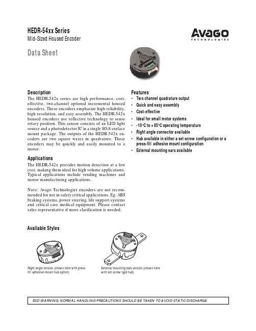
Available StylesRight angle version (shown here with pressfit/adhesive mount hub option)External mounting ears version (shown herewith set screw type hub)DescriptionThe HEDR-542x series are high performance, cost-effective, two-channel optional incremental housed encoders. These encoders emphasize high reliability, high resolution, and easy assembly. The HEDR-542x housed encoders use reflective technology to sense rotary position. This sensor consists of an LED light source and a photodetector IC in a single SO-8 surface mount package. The outputs of the HEDR-542x en-coders are two square waves in quadrature. These encoders may be quickly and easily mounted to a motor.ApplicationsThe HEDR-542x provides motion detection at a low cost, making them ideal for high volume applications. Typical applications include vending machines and motor manufacturing applications.Note: Avago Technologies encoders are not recom-mended for use in safety critical applications. Eg. ABS braking systems, power steering, life support systems and critical care medical equipment. Please contact sales representative if more clarification is needed.Features•Two channel quadrature output•Quick and easy assembly•Cost-effective•Ideal for small motor systems•-10°C to +85°C operating temperature•Right angle connector available•Hub available in either a set screw configuration or a press-fit/adhesive mount configuration•External mounting ears availableHEDR-54xx Series Mid-Sized Housed Encoder Data SheetPackage DimensionsTheory of OperationThe HEDR-542X translates rotary motion of a shaft into a two chan-nel digital output. As seen in the block diagram, the HEDR-542X series has three key parts: a single Light Emitting Diode (LED) light source, a photodetec-tor IC with a set of uniquely con-figured photodiodes, and a pair of lenses. The lens over the LED focuses light onto the codewheel. Light is either reflected or not reflected back to the lens over the photodetector IC. As the codewheel rotates an alternating pattern of light and dark corre-sponding to the pattern of the codewheel falls upon the photo-diodes. This light is used to pro-duce internal signals A and A', and B and B'. As part of this "push-pull" detector system, these signals are fed through compara-tors that are part of the signal processing circuitry to produce the final outputs for channels A and B.DefinitionsCount (N): For rotary motion, the number of bar and window pairs or Counts Per Revolution (CPR) of the codewheel. For lin-ear motion, the number of bar and window pairs per unit length (Lines Per Inch [LPI] or Lines Per mm [LPmm]).One Cycle (C): 360 electrical degree (˚e), 1 bar and window pair.One Shaft Rotation: 360 me-chanical degrees, N cycles (rotary motion only).Line Density: The number ofreflective and non-reflective pairsper unit length, expressed aseither Lines Per Inch (LPI) orLines Per mm (LPmm).Pulse Width (P): The number ofelectrical degrees that an outputis high during one cycle, nomi-nally 180˚e or 1/2 a cycle.Pulse Width Error (∆P): Thedeviation in electrical degrees ofthe pulse width from its idealvalue of 180˚e.State Width (S): The number ofthe electrical degrees between atransition in the output of thechannel B. There are 4 states percycle, each nominally 90˚e.State Width Error (∆S): Thedeviation in electrical degrees ofeach state width from its idealvalue of 90˚e.Phase (φ): The number of electri-cal degrees between the center ofthe high state on the channel Aand the center of the high state ofchannel B. This value is nomi-nally 90˚e.Phase Error (∆φ): The deviationin electrical degrees of the phasefrom its ideal value of 90˚e.SIGNALPROCESSINGCIRCUITRYRV LEDGNDV CCCH ACH BGNDCODEWHEELOutput Waveforms Direction of Motor RotationWhen the codewheel rotates in the clockwise direction (asviewed from the encoder end of the motor), channel A will lead channel B. If the codewheel ro-tates in the counterclockwise direction, channel B will lead channel A.Absolute Maximum RatingsStorage Temperature –40˚C to +85˚C Operating Temperature –10˚C to +85˚C Supply Voltage –0.5 V to 7 V Output Voltage–0.5 V to V CCOutput Current per Channel –2.0 mA to 12 mA Shaft Axial Play± 0.25 mm Shaft Eccentricity Plus Radial Play0.04 mmRadial Play between Housing and Cover0.2 mm – 0.5 mm Distance between Tip of Codewheel Shaft and PC Board 0.4 mm – 0.5 mm Distance between Codewheel and Stopper before Reset 0.25 mm – 0.35 mm Distance between Codewheel and Stopper after Reset 0.75 mm Concentricity Misalignment between Mounted Base 0.12 mm Plate Center Bore and Motor Shaft Frequency16 kHzRecommended Operating ConditionsParameter Symbol Min.Typical Max.Units NotesTemperature T A 085˚C Supply Voltage V CC 4.5 5.0 5.5Volts Ripple < 100 mV p–p LED CurrentI LED 131518mA Load CapacitanceC L100pF2.7 K Ω Pull-UpElectrical Characteristics(Over recommended operating conditions. Typically at 25˚C)Parameter Symbol Min.Typical Max.Units NotesSupply Current I CC1833mAHigh Level Output Voltage V OH 2.4V I OH = –2 mA min. Low Level Output Voltage V OL0.4V I OL = 12 mA max.Encoding CharacteristicsParameter Symbol Typical Max.UnitsPulse Width Error∆P775˚eState Width Error∆S1560˚ePhase Error∆φ1560˚ePosition Error∆Θ50120arcminCycle Error∆C1045˚eMechanical CharacteristicsParameter Dimension Tolerance Units Codewheel Fits these Standard Shaft DiametersPress Fit/Adhesive Mount Hub2, 3, 4+0/–0.01mm Set Screw Hub2, 3, 4, 5, (1/8)(+0/–0.0005)(in.) Allowable Motor Shaft LengthPress Fit/Adhesive Mount Hub Between 7.5 and 8.0mm Set Screw Hub (uses size M1.5 Allen wrench, not included)Between 7.5 and 11.5Bolt Circle Diameter (2 holes)16 to 18mm Mounting Screw Size M2mm (in.)M2.5, (2-56) forexternal mounting earsElectrical InterfacePull up resistors on output pins 2, 3, and 5 have already been inte-grated into the mid-sized encoder. Each of the three encoder out-puts can drive a single TTL load in this configuration.ConnectorsThe connector to be used withthe mid-sized encoder is MolexPart Number 51021-0500. This isa 5 connector crimp wire toboard connector.The connector used on theencoder is orientation proof type,2 different cables configurationrequired for connection to rightangle and axial angle typeencoder.Pin 1GNDPin 2NCPin 3Ch.APin 4 5 VPin 5Ch.BPins configuration HEDR-542x series.Mounting ConsiderationsThe mid-sized encoder must be aligned using the optional align-ing pins, as specified in Figure 1,Standard Mounting Figure 2.Figure 1.Mounting with External Earsby using the optional motor boss shown in Figure 2, or by using an alignment tool or as shown in Encoder Mounting and Assembly.ON BOLT CIRCLE BETWEEN 16 AND 20Encoder Mounting and AssemblyPress Fit Style Encoder1.If not using optional alignmentpins or motor boss to locatethe base plate, slip alignmenttool onto motor shaft. Slipencoder base plate into placeon motor as shown below.Tighten screws or attach withan adhesive. If using alignment tool, remove it.2.Place the hub in the housingassembly on top of the motorshaft. Lining up the guide(connector side) at the bottom of the housing with the slot(indicator side) on the encoder base plate, the housing latches should be aligned to the re-spective baseplate catches now. Press the housing assem-bly downward and slide the hub into and along the shaft, until the 3 latches make con-tact with the catches.ing the end of a pen or other appropriate tool, press the triangular portion of the hous-ing assembly downward. Rec-ommended force is between 3.5 kgf to 4.0 kgf. This will set the codewheel and hub into their proper position through the internal guide of the trian-gular piece. When the triangu-lar piece is released, it should naturally spring back to its original position, eliminating contact between the housing assembly and the codewheel.The encoder is now ready for use.3.Press down the housing assembly until it snaps into place. Recommended force is 3.5 kgf minimum,4.0 kgf nominal, and 4.5 kgf maxi-mum. Note that the encoder is shipped such that the housing assembly and the base plate are not being snappedtogether.while aligning it on the Allen wrench groove. Lining up the guide (connector side) at the bottom of the housing with the slot (indicator side) on the encoder baseplate, the housing Set Screw Style Encoder1.If not using optional alignment pins or motor boss to locate the base plate, slip alignment tool onto motor shaft. Slip encoder base plate into place on motor as shown below.Tighten screws or attach with an adhesive. If using alignment tool, remove it.2.Slip the set screw hub into the shaft. Proper finger-wear must be worn to avoid contamina-tion on codewheel surface (top of hub). Place an Allen wrench into the socket of the set screw latches should be aligned to the respective baseplate catches. Move the housing assembly downward until the 3latches make contact with the catches.SLOT(INDICATOR SIDE)3.Press down the housing assem-bly, holding the set screw andAllen wrench in their initialposition until the housing as-sembly snaps into place. Rec-ommended force is 3.5 kgfminimum, 4.0 kgf nominal,and 4.5 kgf maximum.ing the end of a pen or otherappropriate tool, press thetriangular portion of the hous-ing assembly downward. Rec-ommended force is between3.5 kgf to4.0 kgf. Then applya downward force on the endof the Allen wrench. This setsthe codewheel position bylevering the codewheel upward against internal guide of thetriangular piece. While con-tinuing to apply a downwardforce on both tools, rotate theAllen wrench in the clockwisedirection until the hub setscrew is tightened against themotor shaft. Remove the Allenwrench by pulling it straightout of the housing assembly.When the triangular piece isreleased, it should naturallyspring back to its original posi-tion, eliminating contact be-tween the housing assemblyand the codewheel. The en-coder is now ready for use.Ordering Information*H E D R - 5 4 X X – X X X X XConnector0 = standard/axial1 = right angle/radialShaft01 = 2 mm02 = 3 mm03 = 1/8 inch11 = 4 mm14 = 5 mmResolutionE = 200 CPRHubS2 = Set screw with mounting ears base plateP1 = Pressfit without mounting ears base plateOutput2 = 2 channel*Note:Part numbers currently available:a.)HEDR-5420-ES201b.)HEDR-5420-ES202c.)HEDR-5420-ES203d.)HEDR-5420-ES211e.)HEDR-5420-ES214f.)HEDR-5421-EP111Ordering Information for Alignment ToolHEDR-5900-000Shaft01 = 2 mm02 = 3 mm03 = 1/8"11 = 4 mm14 = 5 mmFor product information and a complete list of distributors, please go to our website: Avago, Avago Technologies, and the A logo are trademarks of Avago Technologies, Pte. in the United States and other countries. Data subject to change. Copyright © 2006 Avago Technologies Pte. All rights reserved. Obsoletes 5988-8671EN5988-9450EN May 2, 2006。
ABS塑料性能和部分牌号介绍

ABS塑料性能和部分牌号介绍ABS塑料- ABS树脂是五大合成树脂之一,其抗冲击性、耐热性、耐低温性、耐化学药品性及电气性能优良,还具有易加工、制品尺寸稳定、表面光泽性好等特点,容易涂装、着色,还可以进行表面喷镀金属、电镀、焊接、热压和粘接等二次加工,广泛应用于机械、汽车、电子电器、仪器仪表、纺织和建筑等工业领域,是一种用途极广的热塑性工程塑料。
ABS树脂是目前产量最大,应用最广泛的聚合物,它将PS,SAN,BS的各种性能有机地统一起来,兼具韧、硬、刚相均衡的优良力学性能。
ABS是丙烯腈、丁二烯和苯乙烯的三元共聚物,A代表丙烯腈,B代表丁二烯,S代表苯乙烯。
ABS塑料-名称化学名称丙烯腈-丁二烯-苯乙烯塑料英文名称 Acrylonitrile Butadiene Styrene plasticABS塑料-性能一般性能ABS外观为不透明呈象牙色粒料,其制品可着成五颜六色,并具有高光泽度。
ABS相对密度为1.05左右,吸水率低。
ABS同其他材料的结合性好,易于表面印刷、涂层和镀层处理。
ABS的氧指数为18~20,属易燃聚合物,火焰呈黄色,有黑烟,并发出特殊的臭味。
力学性能ABS有优良的力学性能,其冲击强度极好,可以在极低的温度下使用;ABS 的耐磨性优良,尺寸稳定性好,又具有耐油性,可用于中等载荷和转速下的轴承。
ABS的耐蠕变性比PSF及PC大,但比PA及POM小。
ABS的弯曲强度和压缩强度属塑料中较差的。
ABS的力学性能受温度的影响较大。
热学性能ABS的热变形温度为93~118℃,制品经退火处理后还可提高10℃左右。
ABS 在-40℃时仍能表现出一定的韧性,可在-40~100℃的温度范围内使用。
电学性能ABS的电绝缘性较好,并且几乎不受温度、湿度和频率的影响,可在大多数1环境下使用。
环境性能ABS不受水、无机盐、碱及多种酸的影响,但可溶于酮类、醛类及氯代烃中,受冰乙酸、植物油等侵蚀会产生应力开裂。
日本横河氧化锆
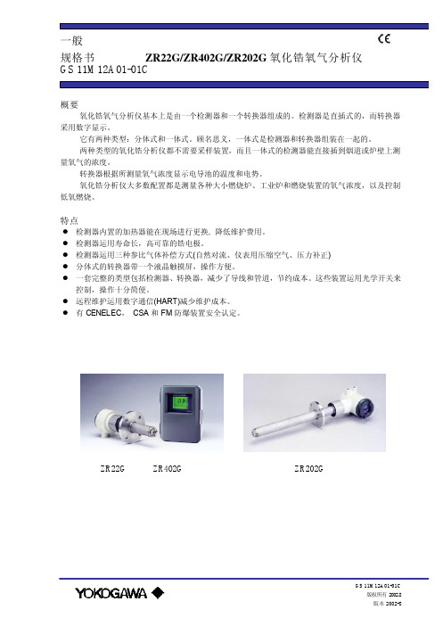
l 应用:在锅炉和加热炉内监视和控制氧气的浓度。
检测器ZR22G
转换器ZR402G
检查阀
信号(6芯屏蔽电缆) 加热器(2芯屏蔽电缆)
参比气体 校验气体
流量计 针形阀
100~240VAC
接点输入 模拟输出、接点输出 数字输出(HART) 气体调节阀
SUS304(JIS)(法兰), 镍基合金 B
(Inconel 600,601) 结构:加热器和热电偶可更换结构;非防爆产品;
相当于国际电气制造业协会 4X/IP 66( 只 适用于经压力补正的熔炉进行再循环) 端子盒材料:铝合金 端子盒颜色:外壳:白色(Munsell 0.6GY3.1/2.0)
盖子:墨绿(Munsell 2.5GY8.4/1.2) 底部:聚亚安酯防腐材料 气体连接:Rc1/4 或 1/4FNPT 配线连接:G1/2,Pg13.5,M20×1.5mm,1/2NPT 安装:法兰安装 探头安装角度: 当探头插入长度为 2m 以下时,
导线两路阻抗小于 10Ω(相当于用
约 11kg(ANSI 150-4)
1.25mm2 电缆,300m 以内)
插入长度为 1.0m:约 8kg(JIS 5K-65)/
结构:外部设备相当于 NEMA 4
约 13kg(ANSI 150-4)
(管道口完全用一个电缆密闭盖封闭)
插入长度为 1.5m:约 10kg(JIS 5K-65)/
配线连接:G1/2,Pg13.5,M20×1.5mm,1/2 NPT
约 15kg(ANSI 150-4)
安装方式:盘装,墙装或 2 英寸管道安装
插入长度为 2.0m:约 12kg(JIS 5K-65)/
HEDR-5421-EP111中文资料

Available StylesRight angle version (shown here with pressfit/adhesive mount hub option)External mounting ears version (shown herewith set screw type hub)DescriptionThe HEDR-542x series are high performance, cost-effective, two-channel optional incremental housed encoders. These encoders emphasize high reliability, high resolution, and easy assembly. The HEDR-542x housed encoders use reflective technology to sense rotary position. This sensor consists of an LED light source and a photodetector IC in a single SO-8 surface mount package. The outputs of the HEDR-542x en-coders are two square waves in quadrature. These encoders may be quickly and easily mounted to a motor.ApplicationsThe HEDR-542x provides motion detection at a low cost, making them ideal for high volume applications. Typical applications include vending machines and motor manufacturing applications.Note: Avago Technologies encoders are not recom-mended for use in safety critical applications. Eg. ABS braking systems, power steering, life support systems and critical care medical equipment. Please contact sales representative if more clarification is needed.Features•Two channel quadrature output•Quick and easy assembly•Cost-effective•Ideal for small motor systems•-10°C to +85°C operating temperature•Right angle connector available•Hub available in either a set screw configuration or a press-fit/adhesive mount configuration•External mounting ears availableHEDR-54xx Series Mid-Sized Housed Encoder Data SheetPackage DimensionsTheory of OperationThe HEDR-542X translates rotary motion of a shaft into a two chan-nel digital output. As seen in the block diagram, the HEDR-542X series has three key parts: a single Light Emitting Diode (LED) light source, a photodetec-tor IC with a set of uniquely con-figured photodiodes, and a pair of lenses. The lens over the LED focuses light onto the codewheel. Light is either reflected or not reflected back to the lens over the photodetector IC. As the codewheel rotates an alternating pattern of light and dark corre-sponding to the pattern of the codewheel falls upon the photo-diodes. This light is used to pro-duce internal signals A and A', and B and B'. As part of this "push-pull" detector system, these signals are fed through compara-tors that are part of the signal processing circuitry to produce the final outputs for channels A and B.DefinitionsCount (N): For rotary motion, the number of bar and window pairs or Counts Per Revolution (CPR) of the codewheel. For lin-ear motion, the number of bar and window pairs per unit length (Lines Per Inch [LPI] or Lines Per mm [LPmm]).One Cycle (C): 360 electrical degree (˚e), 1 bar and window pair.One Shaft Rotation: 360 me-chanical degrees, N cycles (rotary motion only).Line Density: The number ofreflective and non-reflective pairsper unit length, expressed aseither Lines Per Inch (LPI) orLines Per mm (LPmm).Pulse Width (P): The number ofelectrical degrees that an outputis high during one cycle, nomi-nally 180˚e or 1/2 a cycle.Pulse Width Error (∆P): Thedeviation in electrical degrees ofthe pulse width from its idealvalue of 180˚e.State Width (S): The number ofthe electrical degrees between atransition in the output of thechannel B. There are 4 states percycle, each nominally 90˚e.State Width Error (∆S): Thedeviation in electrical degrees ofeach state width from its idealvalue of 90˚e.Phase (φ): The number of electri-cal degrees between the center ofthe high state on the channel Aand the center of the high state ofchannel B. This value is nomi-nally 90˚e.Phase Error (∆φ): The deviationin electrical degrees of the phasefrom its ideal value of 90˚e.SIGNALPROCESSINGCIRCUITRYRV LEDGNDV CCCH ACH BGNDCODEWHEELOutput Waveforms Direction of Motor RotationWhen the codewheel rotates in the clockwise direction (asviewed from the encoder end of the motor), channel A will lead channel B. If the codewheel ro-tates in the counterclockwise direction, channel B will lead channel A.Absolute Maximum RatingsStorage Temperature –40˚C to +85˚C Operating Temperature –10˚C to +85˚C Supply Voltage –0.5 V to 7 V Output Voltage–0.5 V to V CCOutput Current per Channel –2.0 mA to 12 mA Shaft Axial Play± 0.25 mm Shaft Eccentricity Plus Radial Play0.04 mmRadial Play between Housing and Cover0.2 mm – 0.5 mm Distance between Tip of Codewheel Shaft and PC Board 0.4 mm – 0.5 mm Distance between Codewheel and Stopper before Reset 0.25 mm – 0.35 mm Distance between Codewheel and Stopper after Reset 0.75 mm Concentricity Misalignment between Mounted Base 0.12 mm Plate Center Bore and Motor Shaft Frequency16 kHzRecommended Operating ConditionsParameter Symbol Min.Typical Max.Units NotesTemperature T A 085˚C Supply Voltage V CC 4.5 5.0 5.5Volts Ripple < 100 mV p–p LED CurrentI LED 131518mA Load CapacitanceC L100pF2.7 K Ω Pull-UpElectrical Characteristics(Over recommended operating conditions. Typically at 25˚C)Parameter Symbol Min.Typical Max.Units NotesSupply Current I CC1833mAHigh Level Output Voltage V OH 2.4V I OH = –2 mA min. Low Level Output Voltage V OL0.4V I OL = 12 mA max.Encoding CharacteristicsParameter Symbol Typical Max.UnitsPulse Width Error∆P775˚eState Width Error∆S1560˚ePhase Error∆φ1560˚ePosition Error∆Θ50120arcminCycle Error∆C1045˚eMechanical CharacteristicsParameter Dimension Tolerance Units Codewheel Fits these Standard Shaft DiametersPress Fit/Adhesive Mount Hub2, 3, 4+0/–0.01mm Set Screw Hub2, 3, 4, 5, (1/8)(+0/–0.0005)(in.) Allowable Motor Shaft LengthPress Fit/Adhesive Mount Hub Between 7.5 and 8.0mm Set Screw Hub (uses size M1.5 Allen wrench, not included)Between 7.5 and 11.5Bolt Circle Diameter (2 holes)16 to 18mm Mounting Screw Size M2mm (in.)M2.5, (2-56) forexternal mounting earsElectrical InterfacePull up resistors on output pins 2, 3, and 5 have already been inte-grated into the mid-sized encoder. Each of the three encoder out-puts can drive a single TTL load in this configuration.ConnectorsThe connector to be used withthe mid-sized encoder is MolexPart Number 51021-0500. This isa 5 connector crimp wire toboard connector.The connector used on theencoder is orientation proof type,2 different cables configurationrequired for connection to rightangle and axial angle typeencoder.Pin 1GNDPin 2NCPin 3Ch.APin 4 5 VPin 5Ch.BPins configuration HEDR-542x series.Mounting ConsiderationsThe mid-sized encoder must be aligned using the optional align-ing pins, as specified in Figure 1,Standard Mounting Figure 2.Figure 1.Mounting with External Earsby using the optional motor boss shown in Figure 2, or by using an alignment tool or as shown in Encoder Mounting and Assembly.ON BOLT CIRCLE BETWEEN 16 AND 20Encoder Mounting and AssemblyPress Fit Style Encoder1.If not using optional alignmentpins or motor boss to locatethe base plate, slip alignmenttool onto motor shaft. Slipencoder base plate into placeon motor as shown below.Tighten screws or attach withan adhesive. If using alignment tool, remove it.2.Place the hub in the housingassembly on top of the motorshaft. Lining up the guide(connector side) at the bottom of the housing with the slot(indicator side) on the encoder base plate, the housing latches should be aligned to the re-spective baseplate catches now. Press the housing assem-bly downward and slide the hub into and along the shaft, until the 3 latches make con-tact with the catches.ing the end of a pen or other appropriate tool, press the triangular portion of the hous-ing assembly downward. Rec-ommended force is between 3.5 kgf to 4.0 kgf. This will set the codewheel and hub into their proper position through the internal guide of the trian-gular piece. When the triangu-lar piece is released, it should naturally spring back to its original position, eliminating contact between the housing assembly and the codewheel.The encoder is now ready for use.3.Press down the housing assembly until it snaps into place. Recommended force is 3.5 kgf minimum,4.0 kgf nominal, and 4.5 kgf maxi-mum. Note that the encoder is shipped such that the housing assembly and the base plate are not being snappedtogether.while aligning it on the Allen wrench groove. Lining up the guide (connector side) at the bottom of the housing with the slot (indicator side) on the encoder baseplate, the housing Set Screw Style Encoder1.If not using optional alignment pins or motor boss to locate the base plate, slip alignment tool onto motor shaft. Slip encoder base plate into place on motor as shown below.Tighten screws or attach with an adhesive. If using alignment tool, remove it.2.Slip the set screw hub into the shaft. Proper finger-wear must be worn to avoid contamina-tion on codewheel surface (top of hub). Place an Allen wrench into the socket of the set screw latches should be aligned to the respective baseplate catches. Move the housing assembly downward until the 3latches make contact with the catches.SLOT(INDICATOR SIDE)3.Press down the housing assem-bly, holding the set screw andAllen wrench in their initialposition until the housing as-sembly snaps into place. Rec-ommended force is 3.5 kgfminimum, 4.0 kgf nominal,and 4.5 kgf maximum.ing the end of a pen or otherappropriate tool, press thetriangular portion of the hous-ing assembly downward. Rec-ommended force is between3.5 kgf to4.0 kgf. Then applya downward force on the endof the Allen wrench. This setsthe codewheel position bylevering the codewheel upward against internal guide of thetriangular piece. While con-tinuing to apply a downwardforce on both tools, rotate theAllen wrench in the clockwisedirection until the hub setscrew is tightened against themotor shaft. Remove the Allenwrench by pulling it straightout of the housing assembly.When the triangular piece isreleased, it should naturallyspring back to its original posi-tion, eliminating contact be-tween the housing assemblyand the codewheel. The en-coder is now ready for use.Ordering Information*H E D R - 5 4 X X – X X X X XConnector0 = standard/axial1 = right angle/radialShaft01 = 2 mm02 = 3 mm03 = 1/8 inch11 = 4 mm14 = 5 mmResolutionE = 200 CPRHubS2 = Set screw with mounting ears base plateP1 = Pressfit without mounting ears base plateOutput2 = 2 channel*Note:Part numbers currently available:a.)HEDR-5420-ES201b.)HEDR-5420-ES202c.)HEDR-5420-ES203d.)HEDR-5420-ES211e.)HEDR-5420-ES214f.)HEDR-5421-EP111Ordering Information for Alignment ToolHEDR-5900-000Shaft01 = 2 mm02 = 3 mm03 = 1/8"11 = 4 mm14 = 5 mmFor product information and a complete list of distributors, please go to our website: Avago, Avago Technologies, and the A logo are trademarks of Avago Technologies, Pte. in the United States and other countries. Data subject to change. Copyright © 2006 Avago Technologies Pte. All rights reserved. Obsoletes 5988-8671EN5988-9450EN May 2, 2006。
巴氏硬度计使用说明书

巴氏硬度计简介:巴氏硬度计(巴克尔硬度计)是一种压痕硬度计,它以特定压头在标准弹簧力的作用下压入试样,以压痕的深度确定试样的硬度。
巴氏硬度计有100个刻度,每个刻度代表压入0.0076mm的深度。
可测量的材料:铝、铝合金、软金属、塑料、光纤、消防梯、复合材料、橡胶或皮革。
玻璃钢等。
用途巴氏硬度计主要用于测试铝及铝合金。
测试铝型材、板材、管材、棒材及铝合金铸件、锻件、机械加工零件,测试超厚铝合金材料及组装后的铝合金制品(例如铝合金门窗、幕墙、消防梯等)。
相关标准:ASTM B648《巴柯尔硬度计测量铝合金硬度的试验方法》。
巴氏硬度计的另一主要应用是用于测试玻璃钢(玻璃纤维增强塑料)和硬塑料。
大部分玻璃钢制品的产品标准中都要求测试巴氏硬度。
相关标准:GB/T3854—2005《增强塑料巴柯尔硬度试验方法》、ASTM D2583—07《巴氏硬度计测量硬塑料压痕硬度的试验方法》。
巴氏硬度计的改进型935—1、936—1可用于测试很软的金属、软塑料、皮革、橡胶、木材等。
工作原理巴氏硬度计(巴柯尔硬度计)是一种压痕式硬度计,它以特定压头在标准弹簧的压力作用下压入试样表面,以压痕的深浅表征试样硬度的高低。
巴氏硬度计有100个分度,每个分度单位代表压入0.0076mm的深度。
压入越深,读数越高,材料越软。
巴氏硬度公式为:HBa=100-L/0.0076式中:HBa—巴氏硬度符号; L —压痕深度(mm); 0.0076—单位硬度值代表的压痕深度(mm)目录一、概述 (1)二、原理与结构 (2)三、技术参数 (3)四、使用方法 (3)五、仪器校正 (4)六、压针 (5)七、硬度块 (7)八、测量次数 (7)九、型号选择 (8)十、配置 (8)十一、硬度换算表 (9)一、概述巴氏硬度计(巴柯尔硬度计)是一种压痕式硬度计,最早产自美国。
巴氏硬度计有三种型号,其中OU2800-1型巴氏硬度计是代表型产品,应用量最大,一般提到巴氏硬度计主要是指OU2800-1型。
美国传力传感器
美国传力传感器广州南创李工美国传力电子集团于1981年在美国芝加哥成立,是一家专业生产传感器及各种电子衡器等产品的知名企业集团,产品行销全美洲、欧洲、东南亚及澳洲等地区。
基于全球化的经营战略,传力在全球都具有多个分支机构。
在亚洲地区,主要分支机构有台北全立、南京传力、上海全立、常州传力、天津传力等。
传力电子衡器有限公司成立于1997年底,为集团在中国的生产基地,主要生产各类称重传感器、称重仪表、电子衡器以及自动控制检测设备等数十个系列、数百个品种,涵盖各种精度、量程。
在多个国家设立了分支机构或办事处,生产基地遍布美洲、东欧、中国等地;并在中国设立了广州南创传感器事业部,可为用户的实验和生产提供最佳的服务与解决方案。
南京传力拥有完备的科研开发机构、先进的机械制造设备、完善的检测实验手段。
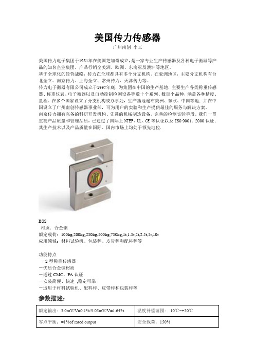
我们一贯重视产品质量和管理品质,已通过了国际上NTEP、UL、CE等认证以及ISO 9001:2000认证;其生产技术以及产品质量在国际、国内市场上均处于领先地位.BSS材质:合金钢额定载荷:100kg,200kg,250kg,500kg,750kg,1t,1.5t,2t,2.5t,5t,10t应用领域:材料试验机、包装秤、皮带秤和配料秤等功能特点-S型称重传感器-优质合金钢材质-通过CMC、PA认证-安装简便、快速,稳定可靠-适用于材料试验机、配料秤、皮带秤和包装秤等参数描述:额定输出:3.0mV/V±0.1%/3.05mV/V±1.64% 温度补偿范围:-10℃~+50℃零点平衡:±1%of rated output 安全载荷:150%蠕变:±0.03% of rated output 输入阻抗:387Ω±5Ω非线性:±0.03% of rated output 输出阻抗:350Ω±3Ω滞后:±0.03% of rated output 绝缘阻抗:≥5000MΩ(50V DC)重复性:±0.03% of rated output 推荐激励电压:10V DC/AC灵敏度温漂:≤0.002%of applied output/℃最大激励电压:15V DC/AC零点温漂:≤0.002% of rated output/℃导线长度:6m可用温度范围:-10℃~+70℃导线颜色:红(+E)黑(-E)绿(+S)白(-S)以上内容技术参数以《OIML60号国际建议》92年版为基础,最新具体变化可查看《JJG669—12transcell广州南创传感器事业部检定规程》美国传力传感器拉压S型称重传感器BSS-100kg, BSS-200kg, BSS-250kg, BSS-500kg, BSS-750kg, BSS-1t, BSS-1.5t, BSS-2t, BSS-2.5t, BSS-5t, BSS-10t BAB-5kg, BAB-7.5kg, BAB-10kg, BAB-15kg, BAB-20kg, BAB-30kg, BAB-50kg, BAB-75kg, BSS-100kg BSSD-15t, BSSD-20t BAC-5kg, BAC-7.5kg, BAC-10kg, BAC-20kg, BAC-30kg, BAC-50kg, BAC-100kg BS-750kg, BS-1000kg, BS-1500kg, BS-2000kg BSA-25kg, BSA-50kg, BSA-100kg, BSA-150kg, BSA-200kg, BSA-250kg BSE-500kg, BSE-1000kg, BSE-1500kg, BSE-2000kg BSS-ESH-1000kg, BSS-ESH -1500kg, BSS-ESH--2000kg, BSS-ESH-2500kg, BSS-ESH 5000kg 悬臂梁式称重传感器SBS-250lb, SBS-250kg, SBS-500kg, SBS-1000kg, SBS-1500kg, SBS-2000kg, SBS-2500kg, SBS-5000kg, SBS-7500kg, SBS-10000kg SB-5t, SB-10t, SB-15t, SB-20t SBSA-1500kg SBSK-25kg, SBSK- 50kg SBST-200kg, SBST-500kg, SBST-1000kg, SBST-2000kg SBT- 0.5t, SBT-1t, SBT-2t, SBT-3t广州南创电子科技有限公司仅供传感器事业部内部使用。
复合酶协同微波提取沙棘叶黄酮工艺优化
第58卷 第4期 广 东 蚕 业 V ol.58,No.04 2024年4月GUANGDONG CANYE Apr . 2024DOI :10.3969/j .issn .2095-1205.2024.04.13复合酶协同微波提取沙棘叶黄酮工艺优化李丽丹 梁丹丹 郑帅印 伊合巴拉依·吾巴提 比丽克孜·阿不都克尤木 刘星星(新疆第二医学院 新疆克拉玛依 834000)摘 要 沙棘中黄酮类化合物含量较高,主要存在于沙棘的叶和果实中,沙棘中黄酮提取工艺的优化是提高黄酮提取效率和降低成本的关键环节。
文章以沙棘叶总黄酮得率为指标,通过单因素试验及响应面法优化复合酶协同微波法提取沙棘叶总黄酮的工艺。
结果显示:影响该法提取沙棘叶黄酮的因素从大到小为提取时间、微波功率、复合酶用量,微波功率与复合酶用量两因素交互作用影响极显著(P <0.01),提取时间对黄酮得率的影响显著(P <0.05);最佳提取工艺条件为复合酶用量3%、果胶酶与纤维素酶的质量比1∶2、微波时间145 s 、微波功率320 W 、料液比1∶100(g /mL ),在此条件下的沙棘叶黄酮得率为7.20%。
关键词 沙棘;黄酮;复合酶;微波提取;响应面 中图分类号:TQ28文献标识码:B文章编号:2095-1205(2024)04-38-06沙棘(Hippophae rhamnoides L .)是一种落叶灌木或小乔木,属于胡颓子科,其果实、叶和根部都具有多种药用价值和保健功效。
沙棘原产于我国,主要分布在华北和西北等地区,新疆是全国沙棘种植园的重要分布区域之一[1]。
沙棘叶中的活性成分较为丰富,主要有黄酮类、有机酸、多糖类、氨基酸等[2],其中具有抗氧化、抗炎和改善免疫功能等多种活性的黄酮类化合物受到了广泛的关注和研究。
微波是一种电磁波,在其电磁场中,被照射的极性小分子会受到电磁能的影响,产生电磁振荡,在1 s 之内,它会引起几十亿次的振动,并迅速产生热,在持续高温下,结构发生膨胀,可促进物质分子溶出。
TPS51200中文资料

VEN = 3.3 V
VREFOUT = 1.25 V (DDR1), IO = 0 A
VVOSNS
Output DC voltage, VO
1
Please be aware that an important notice concerning availability, standard warranty, and use in critical applications of Texas Instruments semiconductor products and disclaimers thereto appears at the end of this data sheet. PowerPAD is a trademark of Texas Instruments.
TPS51200
SLUS812 – FEBRUARY 2008
ELECTRICAL CHARACTERISTICS
Over recommended free-air temperature range, VVIN = 3.3 V,VVLDOIN = 1.8 V, VREFIN = 0.9 V, VVOSNS = 0.9 V, VEN = VVIN, COUT = 3 × 10 µF and circuit shown in Section 1. (unless otherwise noted)
帕克硬管接头说明书
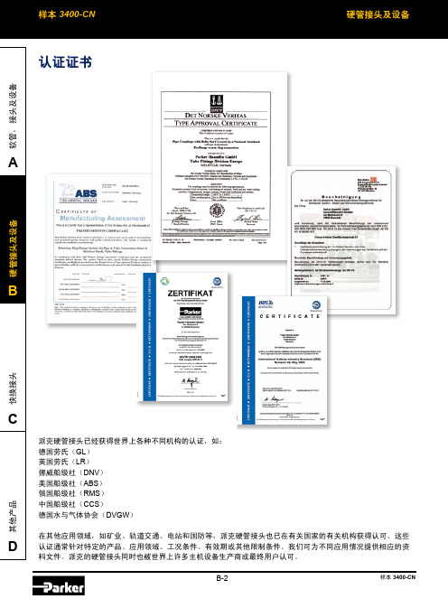
派克硬管接头已经获得世界上各种不同机构的认证,如:德国劳氏(GL)英国劳氏(LR)挪威船级社(DNV)美国船级社(ABS)认证通常针对特定的产品、应用领域、工况条件、有效期或其他限制条件。
我们可为不同应用情况提供相应的资料文件。
派克的硬管接头同时也被世界上许多主机设备生产商或最终用户认可。
目 录技术信息认证证书 .................................................................................................................................... B -2简介 ........................................................................................................................................... B -5硬管接头产品及应用概览 ........................................................................................................... B -6PSR 卡套及特点 .........................................................................................................................B-8DPR 不锈钢卡套及特点 ...........................................................................................................B-10EO-2 型接头及特点..................................................................................................................B-11EO2-FORM 型接头及特点 .......................................................................................................B-13O-Lok ® 型接头及特点 ..............................................................................................................B-15如何选择合适的硬管接头产品..................................................................................................B-17硬管接头产品的国际标准 .........................................................................................................B-25推荐使用的钢管 .......................................................................................................................B-26温度的压降影响 .......................................................................................................................B-28表面处理 ..................................................................................................................................B-29介质兼容性表 ...........................................................................................................................B-30安全指南 ..................................................................................................................................B-32装配指南装配流程简介 ...........................................................................................................................B-33EO 卡套接头装配指南 .............................................................................................................B-34EO-2 卡套接头装配指南 ..........................................................................................................B-38EO 安装工具检查.....................................................................................................................B-42EO2-FORM 装配指南 ..............................................................................................................B-43EO2-FROM 安装工具检查 .......................................................................................................B-48O-Lok ® 装配指南 .....................................................................................................................B-49Parflange ® 工具检查及夹具调整..............................................................................................B-52油口端安装指导 .......................................................................................................................B-53目录可调向接头及旋转螺母安装指导 ..............................................................................................B-57法兰连接安装指导....................................................................................................................B-59硬管布管指导 ..........................................................................................................................B-60安装设备KONU 锥面规 ..........................................................................................................................B-62AKL 测距仪 .............................................................................................................................B-63EO-KARRYMAT.......................................................................................................................B-64EOMAT UNI ............................................................................................................................B-65EO2-FORM F3 ........................................................................................................................B-69KARRYFLARE .........................................................................................................................B-72Parflange ® 1025 ......................................................................................................................B-75Parflange ® 50 .........................................................................................................................B-76EO-NIROMINT ........................................................................................................................B-81手动去毛刺工具 .......................................................................................................................B-82电动去毛刺工具 .......................................................................................................................B-82螺纹识别包 ..............................................................................................................................B-82接头产品EO 接头产品目录.....................................................................................................................B-83如何订购EO 接头......................................................................................................................B-87阀 产品目录..............................................................................................................................B-163阀 技术信息 .............................................................................................................................B-165EO 旋转接头 ............................................................................................................................B-187旋转接头技术信息....................................................................................................................B-188O-Lok ® 产品目录 ...................................................................................................................B-200如何订购O-Lok ® 接头 ..............................................................................................................B-203公制钢管信息及订货 ..............................................................................................................B-236钢管管夹概览 ...........................................................................................................................B-240目录作为管路元件供应商,派克一直致力于为您提供一个更高压力,更易安装,无需维护的无泄漏液压系统。
SMH-50 50 50-150-XL 硬體操作說明書说明书

SMH-50/50/50-150-XL 硬体操作说明书匯出日期:2023-10-19修改日期:2021-04-19•••••••••••••••••••••••目录序言适用机型硬体规格说明外观介绍外形尺寸驱动器规格搬运与安装搬运安装环境条件与注意事项配线与信号周边装置接线图驱动器的连接器与端子说明各式配线图串列向量配线图新代编码器外接类比温感配线图多台四合一串联说明回生电阻选用简易回生电阻选择详细回生电阻选择KTY84温感器与过温度保护功能安装驱动器参数设定版本号编修日期编修内容作者审查核准V1.22022-6-30修正为SMD-34B-50150-xx 硬体操作说明书带电池盒乃维V1.12020-7-23刪去電容吸收能量Ec黃揚程V1.02018/10/04新增SMD-34B-50150-xx 硬体操作说明书杨娟HomePageSYNTEC伺服操作说明书文件资讯文件履历文件资讯文件履历1 序言感谢您长期对本公司产品的使用与支持。
本公司伺服团队不断致力於各项产品的研发,期许本公司产品与服务能给使用者带来最大的效益。
新代高性能驱动器系列产品为本公司最新推出之伺服驱动器,本产品使用高品质之元件与材料,并经过严格测试,采用精密向量控制,具有高精确度、高稳定性、高效率之特性。
本使用说明内容包括驱动器的硬体规格、安装、配线与讯号,能提供给使用者最正确的指引与操作,为充分发挥产品应有的优异性能与维护人员及设备的安全,在使用前请详细阅读本使用手册,并且妥善保存,以备日後调校与保养时使用,若有任何疑虑,请与本公司联络,本公司专业人员将竭诚为您服务。
2 适用机型本操作手册适用於新代 3KWX3+18.5KW四合一驱动器3 硬体规格3.1 说明每部驱动器在出厂前均经过详细品管检查与防撞包装处理,请使用者收到产品後应先检查外观有无撞击损伤,并将外盒与产品上之序号做比对是否一致,若有不符,请第一时间与本公司联络。
型号说明3.2 外观介绍SMH-50/50/50-150-XL驱动器功能模块说明A外供电源输入接点连接380V~440V三相交流电(RST) B马达驱动电源输出接点连接马达侧提供马达电源(UVW)由右至左分别为第一至第四轴C煞车电阻接点煞车电阻接点(P-B)D MIII串行通讯接孔连接上位控制器(MIII讯号)连接串行驱动器 (MIII讯号) E Mini USB接孔连接个人计算机调机使用F I/O讯号端口外接电池端口连接I/O设备(急停、警示灯…等)连接绝对型编码器供电电池G STO讯号端口STO接口,2组安全输入,1组安全功能回授H编码器回授接孔由上至下分别为第一至第四埠。
HS1J中文资料

- 300 -
元器件交易网
RATINGS AND CHARACTERISTIC CURVES (HS1A THRU HS1M)
FIG.1- REVERSE RECOVERY TIME CHARACTERISTIC AND TEST CIRCUIT DIAGRAM
trr +0.5A (-) DUT (+) 50Vdc (approx) (-) PULSE GENERATOR (NOTE 2) 1W NON INDUCTIVE OSCILLOSCOPE (NOTE 1) (+) 0 -0.25A
HS
1.4
Tj=25 0C
1J
-H
10
1
S1
1.6 FORWARD VOLTAGE. (V)
FIG.5- MAXIMUM NON-REPETITIVE FORWARD SURGE CURRENT
40 70
FIG.6- TYPICAL JUNCTION CAPACITANCE
PEAK FORWARD SURGE CURRENT. (A)
.056(1.41) .035(0.90) .210(5.33) .195(4.95)
.012(.31) .006(.15) .008(.20) .004(.10)
Dimensions in inches and (millimeters)
Maximum Ratings and Electrical Characteristics
HS 1F
HS 1G
HS 1J
HS 1K
HS 1M
Units V V V A A
VRRM VRMS VDC I(AV) IFSM VF IR Trr Cj RθJA
圆形插头

18
M12x1 插座 (母头), 系列 CN2 ▶ 插座, M12x1, 5-針, A-编码
19
M12x1 插座 (母头), 系列 CN2 ▶ 插座, M12x1, 5-針, A-编码 ▶ 屏蔽
20
M12x1 插座 (母头), 系列 CN2 ▶ 插座, M12x1, 5-針, B-编码 ▶ 屏蔽
聚酯树脂 氟(石炭)橡胶(FKM)
技术性备注 ■ 规定的保护等级只适用于已安装和检查的状态。
额定电压 电流,最大值
AC
[V]
[A]
240
4
电缆引线 可连接的电缆的最 小/最大直径
直线 180° 呈 90° 弯角
[mm] 4/8
外壳颜色 黑色
重量
注
产品代码
[kg] 0,028 0,027
Fig. 1 Fig. 2
1
BN
3 4
BU BK
产品代码
1834484173 1834484174
额定电压 电流,最大值
DC
AC
[V]
[V]
[A]
75
60
4
安装位置
位置1
电极数目 3
电缆引线 可连接的电缆的 最小/最大直径
直线 180°
[mm]
呈 90° 弯角
-- / 4,5
产品代码 1834484173 1834484174
8941054324 8941054424
Fig. 1
52,5
1
4 2 3
额定电压
电流,最大值
DC
AC
[V]
[V]
[A]
75
60
4
电缆引线 直线 180°
HES12-150080-8中文资料

H HiTRON04/22/2002UNIVERSAL OR U.S. INPUT RANGE AC TO DC EXTERNALWALLMOUNT ADAPTERS SINGLE OUTPUT 12 WATTSSWITCHING POWER SUPPLIES HES12 OR HES12B SERIESFEATURES:LOW COST WALLMOUNT ADAPTER DIVERSE AC PLUGS A V AILABLE MEET DIVERSE SAFETY STANDARDS EMI MEET EN 55022 OR FCC CLASS B CE MARKING COMPLIANCEGENERAL SPECIFICATIONEfficiency: Typ. 80.5%.Switching Frequency: Typ. 56-76K Hz.@ full load. Circuit Topology: Free-running flyback circuit.Transient Response: Output voltage returns typ. 1mSfollowing a 25% load change.Safety Standard: UL1950/EN60950.Class II. Power Density: 2.3 Watts. / Cubic Inch.Operating Temperature: 0 to +40°C. Storage Temperature: -20 to +85°C.Temperature Coefficient: Typ. 0.04% /°C. Cooling: Free air convection.Construction: Impact resistant thermo-plasticenclosure case.Wallmount or Desktop format.Notes: (1) All measurements are at nominal input, full load, and +25°C unless otherwise specified.(2) Load regulation is measured at 230Vac or 120Vac in percentage to indicate the change in output voltage as the load is varied from half load to full load (±%). (3) The exact obtainable load regulation depends upon the output cord selected and load current. Upper data are for 6 ft. (2 m) cord AWG#18 wires.SPECIFICATIONINPUT SPECIFICATIONInput Voltage: HES12 typ. 90-264Vac, rating 100-240Vac.HES12B typ. 90-132Vac, rating 120Vac. Input Connector:HES12: WM1 (U.S.2-blade)/WM3 (Euro-stecker)/DT8(IEC320-2P).HES12B: WM1 (U.S.2-blade). Input Frequency: 47-63Hz. Inrush Current:HES12: Typ. 28A @ 230Vac by adding thermister. HES12B: Typ. 22.5A @ 115Vac.Input Current: HES12 Typ. 0.15A @ 230Vac.HES12B Typ. 0.24A @ 115Vac. Dielectric Withstand: Meet IEC950. EMI: Meet EN 55022 or FCC Class B.Hold-up Time: Typ. 13.2mS@115Vac/42.0mS@230Vac.OUTPUT SPECIFICATIONOutput Voltage: See Ratings Chart. Output Current: See Ratings Chart. Output Wattage : Typ. 12 Watts. Output Connector: Optional. Line Regulation: Typ. 0.1%. Load Regulation: Typ. ±2-3%.Noise & Ripple : Typ. 1.0% peak to peak. OVP: Built-in. By Zener diode clamping. Adjustability: Factory set.Overload Protection (OLP): Fully protected against outputoverload or short circuit. Typ. 120-150% max. load.Consult the factory for special OLP settingMODEL NO. DESCRIPTION: HES12 or B - XXX YYY – S 04/22/2002INPUT AC PLUG: HES12: [1]WM1, [3]WM3, [8]DT8HES12B: WM1OUTPUT CURRENTOUTPUT VOLTAGESERIES NAME (Hitron External Switcher): About 12W.OUTPUT VOLTAGE/CURRENT RATINGS CHARTSINGLE OUTPUTMODEL NO. AC INPUT AC PLUG O/P VOLTAGE O/P CURRENT FORMATHES12-033240-1,3,8 90-264Vac WM1/WM3/DT8 3.3V 2.40A Wallmount/DesktopHES12B-033240 120Vac WM1 3.3V 2.40A Wallmount HES12-050240-1,3,8 90-264Vac WM1/WM3/DT8 5.0V 2.40A Wallmount/DesktopHES12B-050240 120Vac WM1 5.0V 2.40A Wallmount HES12-060200-1,3,8 90-264Vac WM1/WM3/DT8 6.0V 2.00A Wallmount/DesktopHES12B-060200 120Vac WM1 6.0V 2.00A Wallmount HES12-065180-1,3,8 90-264Vac WM1/WM3/DT8 6.5V 1.80A Wallmount/DesktopHES12B-065180 120Vac WM1 6.5V 1.80A Wallmount HES12-075160-1,3,8 90-264Vac WM1/WM3/DT87.5V 1.60A Wallmount/DesktopHES12B-075160 120Vac WM1 7.5V 1.60A Wallmount HES12-090130-1,3,8 90-264Vac WM1/WM3/DT89.0V 1.30A Wallmount/DesktopHES12B-090130 120Vac WM1 9.0V 1.30A WallmounttHES12-120100-1,3,8 90-264Vac WM1/WM3/DT812.0V 1.00A Wallmount/Desktop HES12B-120100 120Vac WM1 12.0V 1.00A Wallmount HES12-150080-1,3,8 90-264Vac WM1/WM3/DT815.0V0.80A Wallmount/DesktopHES12B-150080 120Vac WM1 15.0V0.80A Wallmount HES12-240050-1,3,8 90-264Vac WM1/WM3/DT824.0V0.50A Wallmount/DesktopHES12B-240050 120Vac WM1 24.0V0.50A Wallmount HES12-480025-1,3,8 90-264Vac WM1/WM3/DT848.0V0.25A Wallmount/DesktopHES12B-480025 120Vac WM1 48.0V0.25A Wallmount MECHANICAL DIMENSIONS: MM [INCHES] WEIGHT: 113g (4.0 Oz.)。
氩弧焊焊丝牌号大全
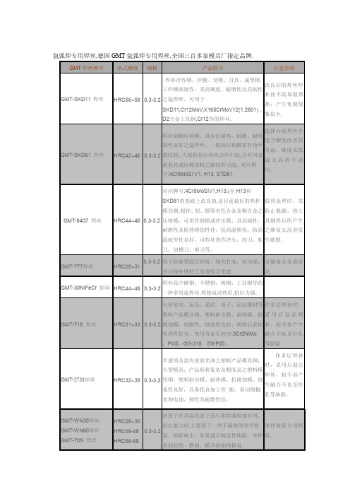
可用于铜合金之焊接修补,也可用于焊接钢
和生铁、铁的接合。
GMT-铝焊丝
5356、5183、5554、5556、5A06铝镁焊丝。 4043、4047铝硅焊丝。 1100、1050、1070、1080纯铝焊丝 6061、6063锌铝焊丝
GMT-铜焊丝
hs221锡黄铜焊丝,hs201,HS212,HS213, HS214,HS215,HS222,HS225铜焊丝。
导热性能好,热强度高,具高温耐磨性及高
韧性,适合于水冷不足的模具,热作钢材应 抛光性能优良,
HRC43-46 0.3-3.2 用于压铸、锻制模及模芯,塑料啷筒、热剪 易切削,高韧性
口刀片。
及延展性
GMT-60E 焊丝
HB320
专用焊高拉力钢之接合,硬面制作之打底,
抗拉强度: 760 0.4-4. 龟裂之焊合。 高强度焊丝,含镍铬合金成
大型家电、玩具、通信、电子、运动器材等 作多层焊补时,
塑料产品模具钢。塑料射出模、耐热模、抗 采 用 后 退 法 焊
HRC31~33 0.3-3.2 腐蚀模,切削性、蚀花性良好,研磨后表面 补,较不易产生 光泽性优良,使用寿命长对应:3Cr2NiMo 融合不良及针孔
,PX5,GS-318,SWP20。
特殊工具钢、耐磨、油冷 。
GMT-PX5焊丝
适用于塑胶射出模之氩焊丝,耐热模、抗腐 HRC-28-30 0.3-3.2
蚀模,切削性,蚀花性良好。
GMT- CENA1焊丝
HRC38-43
可达镜面、可进行蚀化加工,电火花加工。 试用于办公室自动化电气用品、手机、摄像 0.3-3.2 机、光碟盒,吸尘器、电熨斗,尾灯、镜壳、 汽车仪表罩,化妆用品盒等各种模具。焊后切 削性佳,抗腐蚀性能好,抛光性极佳
基尔斯特 2151b-ncfh 型号 nc 连接模块技术手册说明书
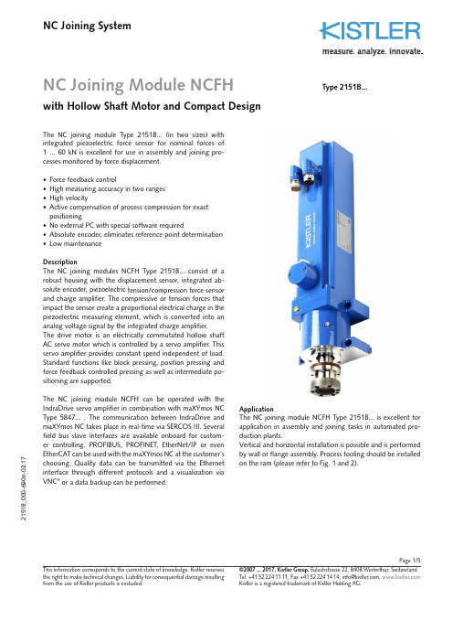
Page 1/5NC Joining Module NCFHwith Hollow Shaft Motor and Compact DesignNC Joining System2151B _000-690e -02.17This information corresponds to the current state of knowledge. Kistler reserves the right to make technical changes. Liability for consequential damage resulting ©2007 ... 2017, Kistler Group, Eulachstrasse 22, 8408 Winterthur, Switzerland The NC joining module Type 2151B... (in two sizes) with integrated piezoelectric force sensor for nominal forces of 1 ... 60 kN is excellent for use in assembly and joining pro-cesses monitored by force displacement.• Force feedback control• High measuring accuracy in two ranges • High velocity• Active compensation of process compression for exact positioning• No external PC with special software required• Absolute encoder, eliminates reference point determination • Low maintenanceDescriptionThe NC joining modules NCFH Type 2151B... consist of a robust housing with the displacement sensor, integrated ab-solute encoder, piezoelectric tension/compression force sensor and charge amplifier. The compressive or tension forces that impact the sensor create a proportional electrical charge in the piezoelectric measuring element, which is converted into an analog voltage signal by the integrated charge amplifier.The drive motor is an electrically commutated hollow shaft AC servo motor which is controlled by a servo amplifier. This servo amplifier provides constant speed independent of load.Standard functions like block pressing, position pressing and force feedback controlled pressing as well as intermediate po-sitioning are supported.The NC joining module NCFH can be operated with the IndraDrive servo amplifier in combination with maXYmos NC Type 5847... . The communication between I ndraDrive and maXYmos NC takes place in real-time via SERCOS III. Several field bus slave interfaces are available onboard for custom-er controlling. PROFI BUS, PROFI NET, EtherNet/I P or even EtherCAT can be used with the maXYmos NC at the customer’s choosing. Quality data can be transmitted via the Ethernet interface through different protocols and a visualization via VNC ® or a data backup can be performed.Type 2151B...ApplicationThe NC joining module NCFH Type 2151B... is excellent for application in assembly and joining tasks in automated pro-duction plants.Vertical and horizontal installation is possible and is performed by wall or flange assembly. Process tooling should be installed on the ram (please refer to Fig. 1 and 2).Page 2/52151B _000-690e -02.17This information corresponds to the current state of knowledge. Kistler reserves the right to make technical changes. Liability for consequential damage resulting ©2007 ... 2017, Kistler Group, Eulachstrasse 22, 8408 Winterthur, Switzerland Tel.+41522241111,Fax+41522241414,****************, Comment about temperature:According to the load profile the size 2 housing can heat up to 80 °C.Cycle time <10 sec please contact technical service.2) Servo amplifier see accessories data sheet 003-125 Type 2180A...3)Evaluation unit maXYmos NC Type 5847B... see data sheet 003-272Technical DataDimensions mm Fig. 1 and 2Assembly options wall or flange assembly Weightsize 1, 10 or 15 kN kg 17 size 2, 30 kN kg 69 size 2, 60 kN kg 75Max. tool weight 1) size 1 kg 50 size 2 kg 100Direction of measurement compression/ tension Measuring rangesize 1 kN 1, 2, 5, 10, 15 size 2 kN 15, 30, 60Practical repeatability mm 0,01Length of strokesize 1 mm 200size 2 mm 400Tool holder mm Fig. 1 and 2Holding brake V/A 24/1Max. movement speed mm/s 300Displacement sensor system absolute encoder Resolution mm 0,001Force sensor piezoelectric Temperature range °C 10 (40)Protection class IP54Linearity in all ranges %FSO ≤1Accuracy class force sensor % 0,5Service life of spindle cycles approx. 10 million (acc. to defined drive profile)Short strokesize 1 mm ≤60 size 2 mm ≤110Lubrication connection standard- (exterior) lubricating nipple Servo amplifier 2) Bosch-Rexroth Type 2180A...Standard interface SERCOS III (internal bus)Evaluation unit 3) maXYmos NC Type 5847...Standard interface PROFIBUS, PROFINET,EtherNet/IP , EtherCAT Power supplyVDC 24 ±5 %1)P ossible radial forces must be considered independent of themounting. Tool weight must be reduced using with manual loading.A bending of the plunger depending on the tool weight must be considered for a horizontal installation.Page 3/52151B _000-6This information corresponds to the current state of knowledge. Kistler reserves the right to make technical changes. Liability for consequential damage resulting ©2007 ... 2017, Kistler Group, Eulachstrasse 22, 8408 Winterthur, Switzerland Tel.+41522241111,Fax+41522241414,****************,The radial forces (for example due to the weight of the tool) must be considered for the installation. An external guide may have to be provided for the plunger.Fig. 2: Dimension NC joining module NCFH Type 2151B... size 2 for measuring range 30 and 60 kNDimension NC joining module NCFH Type 2151B... size 1 for measuring range 1, 2, 5, 10 and 15 kNWarnings and Notes:Lubrication points Electrical connection points Warning high temperaturesPage 4/52151B _000-690e -02.17This information corresponds to the current state of knowledge. Kistler reserves the right to make technical changes. Liability for consequential damage resulting ©2007 ... 2017, Kistler Group, Eulachstrasse 22, 8408 Winterthur, Switzerland Tel.+41522241111,Fax+41522241414,****************, Fig. 3: Functional principle of NC joining system with NC joining module NCFH Type 2151B... and maXYmos NC Type 5847...Included Accessories• NoneOptional Accessories Type/Art. No.• Evaluation unit maXYmos NC 4)(MEM) 5847...• Bearing rail adapter for 35 mm Cap rail including 2 fastening screws M3x10 5700A31• Display module (DIM) with pedestal 5877AZ000• Connection cable maXYmos MEM on DIM, length 5 m1200A161A5• Servo amplifier 2)2180A...CableType/Art. No.• NCFH Motor cable, length 5 m for size 1 KSM333040-5• NCFH Motor cable, length 5 m for size 2 KSM333010-5• NCFH Feedback cable, length 5 mKSM18028885-5• maXYmos Force transmitter cable, length 5 m KSM18028884-5• SERCOS III connection cable, length 5 m KSM18029160-5• Safety zone box cable, 2 cables required), length 1 m KSM18029161-1Other length on request.Functional Principle with maXYmos NC Type 5847...IndraDriveAbsolutwertgeber(Kabellänge max. 5 m)Sicherheitszonenbox Ladungsverstärker piezoelektrischer 2) Servo amplifier Type 2180A... see accessory data sheet 003-125 4)Evaluation unit maXYmos NC Type 5847B... see data sheet 003-272Charge amplifier Safety zone Servo amplifier KSM18029160-51200A161A...(Cable length max. 5 m)Absoulte encoder AC servo motor safety zone box KSM18029161-1Page 5/52151B _000-690e -02.17This information corresponds to the current state of knowledge. Kistler reserves the right to make technical changes. Liability for consequential damage resulting ©2007 ... 2017, Kistler Group, Eulachstrasse 22, 8408 Winterthur, Switzerland Tel.+41522241111,Fax+41522241414,****************, Application ExampleFig. 4: Application example for joining process of bearing and pinOrdering Example Type 2151B05022001NC joining module NCFH Type 2151B..., measuring range 1: 5 kN , measuring range 2: 2 kN , stroke: 200 mm , overall size: 1Ordering Key。
焊丝牌号对照一览表
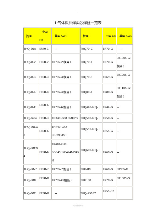
H08Mn2SiA
--
THM-43A
H08MnA
EM12
THM08Mn2Si
H08Mn2Si
THM-43B
H10Mn2
EH14
THM11Mn2SiA
H11Mn2SiA
THM-43C
H10MnSi
--
THM500-NQ-Ⅲ
TH500-NQ-Ⅲ
THM-55G
--
--
THM550-NQ-Ⅲ
E620T5-B3C
--
THY-J552Ni-2
E551T1-Ni2C
E551T1-Ni2C
THY-R502
协议标准
--
THY-J607Ni
E550T5-K1C
--
THY-QD127
EDPMn3-16
--
THY-J602Ni
E601T1-K2C
E91T1-K2
THY-QD172
EDPCrMo-A4-03
--
THY-J957Ni
协议标准
--
THY-ZD-3
EDCr-A2-15
--
THY-J107Ni(M)
协议标准
--
牌号
中国GB
美国AWS
牌号
中国GB
美国AWS
THY-MD301-1
协议标准HRC:42--46
THY-A308LQ
E308LT1-1
E308LT1-1
THY-MD301-4
协议标准HRC:43--48
THQ-50G
ER50-G
ER70S-G(相当)
THG100
ER70-G
ER100S-G
E+H溶解氧分析仪 中文
0 min
0...2000(min)S
ห้องสมุดไป่ตู้
0 min P2
Err.Delay
备注 对于传感器及过程监测 的设置
根据F2中的单位选择 以S或 min来输入报警延时 如P5=AC 或AC+CC,报警延时为有效
6
P3
低 报 的 阈 值 0.00mg/l
0.00...20.00mg/l
0.00% SAT 0.0...200.0% SAT
Altitude
A4
输入测量值的
阻尼系数
1 1...60
1 A4
Damping
测量值阻尼是取一定数 量的测量值作平均值 它被用于稳定波动非常 厉害的测量值 如果输 入1 则没有阻尼
2
5.2.2.SETUP 2
代码
含义
B
功能组
SETUP 2
B1
盐度
选择或范围 的出厂设定
0.0% 0.0...4.0%
lin O2
Sel.Type
该特性的斜体可以是正 或负 模拟或表格特性参阅 02(2) 02(3)
0211
选择电流范围
4-20 0-20
0212
0/4mA对 应 的 值 输入相应的氧
量值或温度值
0.00 mg/l 0.00...20.00 mg/l 0.0%SAT 0.0...200.0% SAT 0.0 -10.0...60.0
数值可以增加或改变 输入的数值会自动地 以电充上升顺序排列.
read O231
Sel.Table
1 O232
No.Elem.
输出X和Y数据组的数量 (X指测量值和Y指相应的 电流值)
1 O233
赫斯曼接头
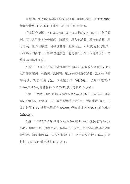
电磁阀、变送器用赫斯曼接头连接器,电磁阀插头,HIRSCHMANN 赫斯曼接头 DIN43650接线盒直角保护套连接器。
产品符合德国DIN43650/EN175301-803标准,A、B、C三个子系列,可以适用于各种电磁阀,液压阀,压力变送器,温度变送器,压力开关,压力传感器,机械设备等,互换性强,可以满足不同客户、不同场合的需求。
有各种普通黑色,透明带指示灯,带电路保护,带整流器的插头可选。
A型——2+PE/3+PE;插针间距为18mm,圆形或方型底座,***应用于液压阀,电磁阀,比例阀,压力传感器及变送器,温度传感器等领域。
额定电流10A,电缆密封管PG9/PG11,适用电缆直径6-8mm/8-10mm,壳体材料PA+30%GF,触点材料CuZn(Ag)。
B型——2+PE;插针间距有两种规格9mm或11mm,该产品在电磁阀,液压阀,比例阀,伺服阀等领域有***应用。
额定电流10A,电缆密封管PG9,适用电缆直径6-8mmm,壳体材料PA+30%GF,触点材料CuZn(Ag)。
C型——2+PE/3+PE;插针间距为8mm或9.4mm;该系列产品外形小巧,插拔方便,价格便宜。
***应用于压力、温度等各种自动化测量领域。
额定电流6A,电缆密封管PG7,适用电缆直径4-6mm,壳体材料PA+30%GF,触点材料CuZn(Ag)。
- 1、下载文档前请自行甄别文档内容的完整性,平台不提供额外的编辑、内容补充、找答案等附加服务。
- 2、"仅部分预览"的文档,不可在线预览部分如存在完整性等问题,可反馈申请退款(可完整预览的文档不适用该条件!)。
- 3、如文档侵犯您的权益,请联系客服反馈,我们会尽快为您处理(人工客服工作时间:9:00-18:30)。
High Temperature 125°C Two Channel Optical Incremental Encoder Modules Technical DataHEDT-9000HEDT-9100Features• High Performance • High Resolution • Low Cost• Easy to Mount• No Signal Adjustment Required• Insensitive to Radial and Axial Play • Small Size• -40°C to 125°C Operating Temperature• Two Channel Quadrature Output• TTL Compatible • Single 5 V SupplyDescriptionThe HEDT-9000 and the HEDT-9100 series are highperformance, low cost, optical incremental encoder modules that operate to 125°C. When used with a codewheel, these modules detect rotary position. Themodules consist of a lensed (LED)source and a detector IC enclosed in a small C-shaped plastic pack-age. Due to a highly collimated light source and unique photodetector array, thesemodules are extremely tolerant to mounting misalignment.The two channel digital outputs and the single 5 V supply input are accessed through five 0.025inch square pins located on 0.1inch centers.ESD WARNING: NORMAL HANDLING PRECAUTIONS SHOULD BE TAKEN TO AVOID STATIC DISCHARGE.Package Dimensions26.67 (1.05)H E D S -9X 0015.2 (0.60)C L 17.27 (0.680)20.96 (0.825)1.85 (0.073)8.64 (0.340) REF.ALIGNING RECESS 2.44/2.41 DIA.(0.096/0.095)2.16 (0.085) DEEP 1.02 ± 0.10 (0.040 ± 0.004)5.1 (0.20)X00YYXXOPTION CODE 0.63 (0.025) SQR. TYP.2.54 (0.100) TYP.DATE CODE1.0 (0.04)3.73 ± 0.05 (0.147 ± 0.002)2.67 (0.105) DIA. MOUNTING THRU HOLE 2 PLACES 2.44/2.41 X 2.79 (0.096/0.095 X 0.110) 2.16 (0.085) DEEP OPTICAL CENTER1.52 (0.060)20.8(0.82)11.7 (0.46)8.6 (0.34)1.78 ± 0.10 (0.070 ± 0.004)2.92 ± 0.10 (0.115 ± 0.004)10.2 (0.400)5.46 ± 0.10 (0.215 ± 0.004)OPTICALCENTER LINE 2.54(0.100)2.21(0.087) 5.8(0.23)6.35 (0.250) REF.ALIGNING RECESS 2.44/2.41 X 2.79(0.096/0.095 X 0.110) 2.16 (0.085) DEEP4.11 (0.162)ALIGNING RECESS 2.44/2.41 DIA. (0.096/0.095)2.16 (0.085) DEEP OPTICAL CENTER45°8.81(0.347)11.9 (0.47)4.75 ± 0.10 (0.187 ± 0.004)2.9 (0.11)1.8 (0.07)6.9 (0.27)V C CG N D5 C H . B 4 V C C 3 C H . A 2 N .C .1 G N DSIDE ASIDE BTYPICAL DIMENSIONS IN MILLIMETERS AND (INCHES)元器件交易网2Standard resolutions for the HEDT-9000 are 500 CPR and 1000 CPR for use with a HEDS-6100 codewheel or equivalent. For the HEDT-9100, standard resolutions between 96 CPR and 512 CPR are available for use with a HEDS-5120 codewheel or equivalent.ApplicationsThe HEDT-9000 and 9100 provide sophisticated motion detection at a low cost, at temperatures to 125°C, making them ideal for high volume automotive applications.Note: Agilent Technologies encoders are not recommended for use in safety critical applications. Eg. ABS braking systems, power steering, life support systems and critical care medical equipment. Please contact sales representative if more clarification is needed. Theory of OperationThe HEDT-9000 and 9100 are C-shaped emitter/detector modules. Coupled with a codewheel, they translate the rotary motion of a shaft into a two-channel digital output.As seen in the block diagram, each module contains a single Light Emitting Diode (LED) as its light source. The light is collimated into a parallel beam by means of a single polyetherimide lens located directly over the LED. Opposite the emitter is the integrated detector circuit. This IC consists of multiple sets of photodetectors and the signal processing circuitry necessary to product the digital waveforms. The codewheel rotates between the emitter and detector, causing the light beam to be interrupted Block DiagramOutput Waveformsby the pattern of spaces and barson the codewheel. Thephotodiodes which detect theseinterruptions are arranged in apattern that corresponds to theradius and design of the code-wheel. These detectors are alsospaced such that a light period onone pair of detectors correspondsto a dark period on the adjacentpair of detectors. The photodiodeoutputs are then fed through thesignal processing circuitryresulting in A, A, B, and B. Twocomparators receive these signalsand produce the final outputs forchannels A and B. Due to thisintegrated phasing technique, thedigital output of channel A is inquadrature with that of channel B(90 degrees out of phase).DefinitionsCount (N): The number of barand window pairs or counts perrevolution (CPR) of thecodewheel.3Absolute Maximum RatingsStorage Temperature, T S .....................................................................-40°C to 125°C Operating Temperature, T A ................................................................-40°C to 125°C Supply Voltage, V CC ......................................................................................-0.5 V to 7 V Output Voltage, V O ........................................................................................-0.5 V to V CC Output Current per Channel, I out .................................................-1.0 mA to 5 mA Pulse Width (P): The number of electrical degrees that an output is high during 1 cycle. This value is nominally 180°e or 1/2 cycle.Pulse Width Error (∆P): The deviation, in electrical degrees of the pulse width from its ideal value of 180°e.State Width (S): The number of electrical degrees between atransition in the output of channel A and the neighboring transition in the output of channel B. There are 4 states per cycle, each nominally 90°e.State Width Error (∆S): The deviation, in electrical degrees, of each state width from its ideal value of 90°e.Phase (φ): The number of elec-trical degrees between the center of the high state of channel A and the center of the high state of channel B. This value is nominally 90°e for quadrature output.Phase Error (∆φ): The deviation of the phase from its ideal value of 90°e.Direction of Rotation: When the codewheel rotates in the direction of the arrow on top of themodule, channel A will lead channel B. If the codewheelrotates in the opposite direction,channel B will lead channel A.Optical Radius (R op ): The dis-tance from the codewheel’s center of rotation to the optical center (O.C.) of the encoder module.Recommended Operating ConditionsParameter SymbolMin.Typ.Max.Units NotesTemperature T -40125°C Supply Voltage V CC 4.55.5Volts Ripple < 100 mV p-p Load Capacitance C L 100pF 3.3 k Ω pull-up resistor Count Frequencyf100kHzVelocity (rpm) x N60Note: The module performance is guaranteed to 100 kHz but can operate at higher frequencies.Encoding CharacteristicsEncoding Characteristics over Recommended Operating Range and Recommended Mounting Tolerances.These Characteristics do not include codewheel/codestrip contributions.Description Sym.Typ.Case 1 Max.Case 2 Max.Units NotesPulse Width Error ∆P 73545°e Logic State Width Error ∆S 53545°e Phase Error∆φ21520°eCase 1:Module mounted on tolerance circle of ±0.13 mm (±0.005 in.).Case 2:HEDT-9000 mounted on tolerances of ±0.50 mm (0.020").HEDT-9100 mounted ontolerances of ±0.38 mm (0.015").元器件交易网Electrical CharacteristicsElectrical Characteristics over Recommended Operating Range, typical at 25°C.Parameter Symbol Min.Typical Max.Units Notes Supply Current I CC1740mAHigh Level Output Voltage V OH 2.4Volts I OH = -40 µA max. Low Level Output Voltage V OL0.4Volts I OL = 3.2 mARise Time t r200ns C L = 25 pFFall Time t f50nsR L = 11 kΩ pull-up Recommended Codewheel CharacteristicsFigure 1. Codestrip Design.Codewheel OptionsOptical HEDS CPR Radius Series(N)Option mm (in.)512096K11.00 (0.433) 5120100C11.00 (0.433) 5120192D11.00 (0.433) 5120200E11.00 (0.433) 5120256F11.00 (0.433) 5120360G11.00 (0.433) 5120400H11.00 (0.433) 5120500A11.00 (0.433) 5120512I11.00 (0.433)6100500A23.36 (0.920)61001000B23.36 (0.920)Parameter Symbol Minimum Maximum Units Notes Window/Bar Ratioφw/φb0.7 1.4Window Length L 1.8 (0.07) 2.3 (0.09)mm (inch)Absolute Maximum R C R OP + 1.9 (0.075)mm (inch)Includes eccentricity Codewheel Radius errorsMounting ConsiderationsHEDT-9001 OptionHEDS-6100 Option00Resolution (Cycles/Rev)A - 500Ordering InformationShaft Diameter 06 - 1/4 in.09 - 1/2 in.08 - 3/8 in.10 - 5/8 in.601020304050608091011121314HEDS-6100A***01020304050608091011121314HEDS-5120A *********C ******D *E **F *G ******H *****I *K**AC D E G IHEDT-9001*HEDT-9100*****HEDT-9101******HEDT-910 Option HEDS-5120 OptionShaft Diameter 01 - 2 mm 11 - 4 mm 02 - 3 mm 14 - 5 mm 03 - 1/8 in.12 - 6 mm 04 - 5/32 in.13 - 8 mm05 - 3/16 in.06 - 1/4 in.Resolution (Cycles/Rev)C - 100 CPR D - 192 CPR E - 200 CPRG - 360 CPR A - 500 CPR I - 512 CPR00Lead 0 - Straight Leads 1 - Bent Leads/semiconductors For product information and a complete list of distributors, please go to our web site.For technical assistance call:Americas/Canada: +1 (800) 235-0312 or (408) 654-8675Europe: +49 (0) 6441 92460China: 10800 650 0017Hong Kong: (+65) 271 2451India, Australia, New Zealand: (+65) 271 2394 Japan: (+81 3) 3335-8152(Domestic/Interna-tional), or 0120-61-1280(Domestic Only) Korea: (+65) 271 2194Malaysia, Singapore: (+65) 271 2054Taiwan: (+65) 271 2654Data subject to change.Copyright © 2002 Agilent Technologies, Inc. Obsoletes 5988-2577ENFebruary 11, 20025988-5280EN。
