沃特斯 新风主机
艾膈xStorage家型单相,3.6kW,4.2kWh,AC耦合,灰色 蜂窝模式,PV6说明书
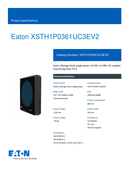
Eaton XSTH1P0361UC3EV2Eaton xStorage Home single-phase, 3.6 kW, 4.2 kWh, AC coupled, Grey/Honeycomb, PV 6General specificationsEaton xStorage Home single-phase XSTH1P0361UC3EV2XST 1Ph 3.6kW 4.2kWh Grey/Honeycomb3553340100666890 mm1230 mm 220 mm 159 kgCE Marked CE LVD RoHS CompliantEN 61000-6-3 EN 61000-6-2EN 62109 (part 1:2010, part 2:2011)Product NameCatalog Number Model CodeEANProduct Length/Depth Product Height Product Width Product Weight Compliances Certifications0.99 (Grid-Tie), 0.8 (ind) - 0.8 (cap) (Grid Tie-PF regulation, Off-Grid)3,6 kW17.4 A230V97%Residual current circuit breaker (RCCB)Overload-/temperature protectionShort-circuit protectedBuilt-in batteryWith data loggingEthernetWLANEmergency power compatible3600 VA550 V20 AIP20Power metering of critical loads and PV production Eaton xstorage Home Brochure enxStorage Home BrochurexStorage Home Product team guidelinesxStorage Home Installation manualEaton xStorage Home Quick Start Guide xStorage Home User Interface Manual xStorage Home User manualEaton xStorage Home Safety GuidelinesHow to onboard xStorage Home into the Cloud xStorage Home - Technical data sheetOutput power factorPower rangeAC current - maxAC inputEfficiency (PV to grid) - max Fitted with:Nominal output powerDC voltage on PV input - max Input Current on PV Input – Max Degree of ProtectionLED indicator colorMetering capability BrochuresCase studiesManuals and user guidesMultimediaTechnical data sheetsGreen (ON): Normal status. Red (ON): Fault status. Inverter is unable to connect to the grid.Green (Blinking): Communication activitySpecial featuresThe xStorage Home system offers three different power inverter ranges.Nominal DC Operating Voltage – Max550 VCoolingNatural airflowStorage temperature - max40 °CTopologyTransformerlessBattery nominal capacity4,2 kWhProtective classIAC wiring systemsSingle phase/N/PE, TN, TT, IT (additional fuse or CB required)Relative humidity - min5 %C/D DC current - Max70 ANominal AC output current15.6 AStandby losses< 10WStorage temperature - min-10 °CDC battery voltage - min74.4 VOver voltage categoryOVC II (PV and Battery), OVC III (AC grid/load)PhaseSingle phaseOperating temperature - min0 °CRelative humidity - maxEfficiency (Battery to AC) - Max>90%Grid integrationDC and AC coupledNumber of MPPT Trackers2Noise level35 dB (indoor application)Rated MPP-voltage – min240 VMaterial coverPlasticNominal DC Operating Voltage – Min 100 VPower consumption3.6 kWOperating temperature - max30 °CHazard substance restrictionLead free, compliance with RoHS GP2Initial feeding voltage150 VProtocolHTTPAPIRESTMPPT efficiency> 99%Recommended PV power3 kWp - 7 kWpSolar DC switchYesNominal AC grid voltage230 V (Grid-Tie), 230 V ± 3 % (Off-Grid)DC battery voltage - max98.4 VEaton Corporation plc Eaton House30 Pembroke Road Dublin 4, Ireland © 2023 Eaton. All rights reserved. Eaton is a registered trademark.All other trademarks areproperty of their respectiveowners./socialmedia35 A90 V< 3%AC Synchronized operation 50 Hz / 60 Hz ± 1 Hz 2000 m Standard550 VBattery voltage rating Total Harmonic Distortion (THD)Nominal frequencyAltitude Display Rated MPP-voltage – max。
全热交换器技术参数

全热交换器技术参数1.概述1.1 工作原理XFHQ系列全热交换器采用先进科技及工艺,芯体用特殊纸质经过化学处理加工而成,对温度、湿度、冷热能量回收起到最佳效果。
高效换热芯体,当室内空调排风与室外新风分别呈交叉方式流经换热芯体时,由于平隔板两侧气流存在温度差,产生传热,夏季运行时,新风从空调排风获得冷能,使温度降低;在冬季运行时,新风从空调排风中获得热能,使温度升高,这样通过换热芯体的热交换过程使新风从空调排风中回收了能量。
1.2特点双向换气功能将室外新风空气经过过滤后送入室内的同时,将室内污浊空气排出室外,彻底改善室内空气品质;静音设计内置空调专用低噪音离心风机,机箱内部覆有高效的吸音材料,全静音设计,人性化体现;能量回收机组内置高效的热交换器,将排出去的室内空气与送进来的室外空气进行冷热交换,在提供舒适温度空气的同时回收能量,节约能源;控制方便电气系统采用二次回路设计,使用开关面板,启动停止机组安全快速简单,可选择远程集中控制系统,与多联机室内机联网控制。
317MDV4+i 直流变频智能多联中央空调3181.3 命名法A,B,……Z 设计序列 S-三相,单相缺省Z-纸芯式、L-轮转式、P-普通式 D-吊顶式、L-立柜式 新风量,单位100m 3/h XFH-显换热式新风机 XFHQ-全换热式新风机MDV4+i直流变频智能多联中央空调2.参数2.200~1200m3/h的产品采用发泡风道,具备旁通功能;2500~12000m3/h机型不带网络集中控制功能。
3.表中噪音是在额定静压安装条件半消音室测得,实际使用条件下的运行噪音可能高于此值,请根据设计安装具体条件,考虑相应的消音措施。
319MDV4+i直流变频智能多联中央空调2.200~1200m3/h的产品采用发泡风道,具备旁通功能;2500~12000m3/h机型不带网络集中控制功能。
3.表中噪音是在额定静压安装条件半消音室测得,实际使用条件下的运行噪音可能高于此值,请根据设计安装具体条件,考虑相应的消音措施。
麦克维尔产品手册

750
800
800
850
850
900
950
1000
1100
1200
1300
输入功率
kW
447.3
462
489.1
504.5
518.5
526.4
558.4
587.5
619.9
680.1
759
824.7
电源
380V/3N〜/50Hz
注:■ 以上选型适用于冷冻水进/出水温度为 12℃/7℃,冷却水进/出水温度为 32℃/37℃,换热器流程数为 2 流程。
40 热泵热水机组
模块式空气源热泵热水机组MHA
42 末端空调机组
组合式空气处理机组 MDM 洁净室用空气调节机组 MDX 单壁柜式空气处理机组 MSW 双壁柜式空气处理机组 MDW 超薄吊顶式空气处理机组 MHW 卧式暗装风机盘管 MCW 立式暗装风机盘管 MFCW 立式明装风机盘管 MFMW 天花嵌入式风机盘管 MCKW 卧式明装风机盘管 MCMW 吊顶式全热热回收新风机组 HRB
79 轻型商用空调机组
天花嵌入式分体空调器 MCK-T 明装吊顶/座地式分体空调器 MCM-D 暗装吊顶式分体空调机组 MCC-T 风冷冷风/热泵型管道式空调机 MDB“T”系列 风冷冷风/热泵型管道式空调机 MDB“M”系列 风冷冷风/热泵型管道式空调机 MDB“S”系列 “旋风”系列水冷柜机 MWCP 屋顶式空调机组 MRT
新风机内全热交换器性能分析

新风机内全热交换器性能分析樊启志【摘要】近几年家用小型新风机产品在市面上快速出现,但其全热交换效率很少能完全达到国家标准.文章着重对全热交换器国际主流标准做了简单对比,并对其性能进行了简要分析.【期刊名称】《建筑热能通风空调》【年(卷),期】2019(038)004【总页数】3页(P67-69)【关键词】全热交换器;全热交换效率;中性膜【作者】樊启志【作者单位】上海泰豪环境科技有限公司【正文语种】中文家用小型新风机(额定风量在 800 m3 / h 以下)作为一个区分空气净化器的产品,除了能有效为室内输送新鲜洁净空气的特点外,还能进行部分能量回收(设备内基本带有一个全热交换器)。
这样,带全热交换器的新风机有效地解决了提供室内空气品质与空调节能之间的矛盾。
但是受全热交换器本身技术以及材料成本的限制,目前市面上的小型新风机很少能做到在额定风量下有较高的全热交换效率。
另外,由于新风机全热交换效率的测定条件比较困难,尤其是焓交换效率需要在专门的焓差实验室进行测试,而建立一套焓差实验室对中小企业前期投入比较高。
针对上述问题,文中对全热交换器进行了综合性概述分析。
重要对比了一下目前关于全热交换器的主流标准,简要分析了全热交换器的作用机理,以及目前主流板式全热交换器的相关问题。
1 主要标准对比目前各国参照的全热交换器能量回收装置标准主要如下[1] :1)由美国供暖制冷与空调工程师协会发布的ANSI/ASHRAE 84-2008 Method of Testing Air-to-Air Heat/Energy Exchangers(简称ASHERE 84或美标)。
该标准将进行实验的热交换器分类为:旋转式能量回收轮、热管换热器、热虹吸管式换热器、盘管回收环形管状换热器。
主要参数有热湿交换效率,空气摩擦压降,排风压降,空气污染以及漏风量等。
2)由德国标准化学会发布的 DIN EN 308-1997 Test Procedures for Establishing Performance of Air to Air Flue Gases Heat Recovery Devices (简称 EN 308 或欧标)。
艾尔斯派新风净化机画册(新)
空气——人类一刻也离不开的生命基础艾尔斯派恒氧恒净新风净化系列改变大环境但可以改变家居小气候这里有着德国范围内最密集的科研机构。
全德约11%的科研成果均出自这里。
在20世纪初,欧洲正处于第二次工业革命的高潮期;人类工业巨大发展的同时,严重破坏了自然环境;空气污染和气候恶化尤为突出。
德国气候环境研究领域的权威专家,William. Raul深知气候环境对人类健康的重要性,为了让人们拥有健康舒适的室内气候环境, William. Raul在斯图加特创建了研发空调类综合技术的实验室和企业,并把企业命名为——AIRSPA。
William. Raul根据多年经过数十万人实验;得出人体最健康、最舒适的室内气候是由:①温度 ②湿度 ③洁净度 ④氧气含量 ⑤有害气体浓度 ⑥室内风速——6大室内气候要素主导的;并且6大要素要一起达到最佳舒适值,才能实现完美的家居气候——人类最健康最舒适的家居气候环境。
实验为AIRSPA气候系统的奠定了研发方向和理论基础。
2010年,AIRSPA艾尔斯派积极开拓中国市场,把中国列为其全球战略的重要组成部分,并选择传统空调产业链极为成熟的广东顺德设立大中华区的生产基地,为中国高端用户带来了高品质的产品和完美的室内空气享受,感受清新的、诗意的艾尔斯派。
(广东艾尔斯派电器是德国艾尔斯派在中国的生产基地)目录目前室内外空气质量艾尔斯派新风净化解决方案艾尔斯派暗藏式新风净化选配参考艾尔斯派暗藏式新风净化产品参数表艾尔斯派过滤网清洗或更换操作步骤VMC (住宅微循环空气置换系统)什么是新风净化机艾尔斯派暗藏式新风净化安装示意图艾尔斯派明装新风净化安装示意图艾尔斯派新风净化与普通新风净化机的对比艾尔斯派明装新风净化与产品参数表11111111111艾尔斯派德国品牌证书艾尔斯派高效过滤网过滤效率检验报告艾尔斯派高效过滤网过滤效率检验报告艾尔斯派高效过滤网过滤效率检验报告艾尔斯派德国专利证书艾尔斯派中国专利证书艾尔斯派中国专利证书中国3C产品认证证书ISO9001国际质量体系认证证书ISO9001国际质量体系认证证书中国节能产品认证证书空气质量传感器检验报告艾尔斯派证书一览表莱蒙国际南京水榭阳光 样板房莱蒙国际南昌莱蒙都会 样板房艾尔斯派恒氧恒净系列客户案例莱蒙国际房地产与艾尔斯派合作,引入航天技术,首度将航天技术——恒氧恒净民用化,采用航天三级滤网技术,是目前少数能将PM2.5过滤掉98%以上的滤网。
cxw-220-et03s产品知识与cxw-220-jd01g产品知识

1规格及附件1:规格12外部装配部件图3 外形尺寸图4 安装方法及注意事项1:安装方法①吸油烟机最低部位与炉灶表面的参考距离为670~750mm,但该距离应至少为650mm。
如果炉灶规定了较大的安装距离,则应以炉灶的规定为准。
②如安装参考图所示,在墙上钻5个深度约为60mm的Φ10孔,最上方2孔埋入2个Φ 10金属膨胀螺栓,其余3孔埋入Φ 10塑料膨胀管,用膨胀螺栓的螺母和2只Φ5木螺钉将主机挂板紧固在墙上(中间一孔暂不拧螺钉)。
③若需安装上装饰罩,请在主机挂板正上方的适当位置,钻2个Φ10孔(如安装参考图所示),分别埋入2只Φ10塑料膨胀管,用Φ5只木螺钉将上装饰罩挂板水平紧固在墙上。
④将主机挂在主机挂板上,并确保主机挂牢和平稳。
⑤如安装参考图所示,将Φ5木螺钉拧入主机挂板的中间孔,以防主机掀翻。
⑥将出风管插入出风口环槽底部,用2只ST4*10自攻螺钉将出风管固定在出风口上,并在衔接处用铝箔胶带固定密封。
⑦将出风管从预先钻好的Φ185墙孔中引出室外,室外的出口应低于室内。
若墙内排烟口径小于出风管时,可采用转接头进行转接,连接方式见右图。
注意:1. 加装转接头后,会降低吸烟排气能力。
2.安装时请将出风管充分拉展开,避免排气不畅和增加噪音,并将出风管多余部分截出。
⑧拉出上装饰罩,用2只M4*8螺钉将其紧固在上装饰罩挂板上。
⑧将油杯水平插入器具底部的油杯挂脚中,并平推到位。
⑩接通器具的电源,试运行机器,确认机器的各功能是否正常。
2:注意事项①.本器具请勿与建筑物的金属部(壁内钢丝等)接触,施工时请注意。
②.请勿将机体埋入墙内,墙壁内的钢丝有漏电场合,会流至机体。
③.使用灶具的宽度应在吸油烟机宽度之内。
④. 吸油烟机排除的气体不应排到用于排出燃烧燃气或其他燃料的烟雾使用的热烟道中。
⑤.请使用随机附件中的出风管,不可采用其他规格的出风管,否则会影响吸烟排气效果。
⑥.出风管不可拉开太长和弯曲太多,以免影响吸烟排气效果。
蜂巢微型快动开关ZX系列数据手册说明书
MICRO SWITCH™ Subminiature Basic SwitchesDatasheet2What makes our switches better?Designed to operate in a variety of applicationsCurrent carrying capacity, up to 3 A, allows for a solution inmany applications where space is a premiumCost-effective switch in a compact packageSubminiature switch package designed to meet a widerange of temperature requirementsMICRO SWITCH™ ZX Series Subminiature Basic SwitchesHoneywell’s MICRO SWITCH™ ZX Series is a subminiature snap-action switch from the family of Z seriessubminiature basic switches. Although small in size, the ZX Series is rated for controlling electrical loads ranging from logic-level/computer-based circuits to limited power-duty switching (up to 3 A/125 Vac). The ZX subminiature switch package is available with either solder terminals or a variety of different styles of printed circuit board (PCB) terminals to fulfill the requirements for electrical connectivity.A wide variety of stainless steel levers are available and when combined with the subminiature package size, can adapt the ZX Series to a wide range of applications. T o enhance the versatility of ZX switches, the family is certified to UL, cUL, ENEC, and CQC for worldwide use. The ZX Series is the right choice for a cost-effective subminiature switch package.RIGHT SWITCH FOR THE RIGHT APPLICATIONRELIABILITY • ELECTRICAL RATING3Features and BenefitsSMALL PACKAGE SIZESubminiature package size (6,5 mm x 12,8 mm [0.25 in x 0.50 in]) allows the MICRO SWITCH™ ZX Series switch to fit in applications where other sensors or switches are too large.WELL SUITED FOR POWER-DUTY AND LOGIC-LEVEL LOADSZX switch design helps assure control of limited power-duty switching with silver contacts or logic-level (low voltage, and milliamperes) with gold-plated contacts.DESIGN FLEXIBILITYDesigned with a pin plunger for actuation, the ZX Series is also available with various styles of levers. The optional levers expand the versatility of the switch in the application. In addition, the ZX Series features a variety of terminations designed to provide flexibility for the electrical connectivity. Certified to cUL, UL, ENEC, and CQC for global applications, as well as RoHS compliant.WORLDWIDE AVAILABILITYEntire family of ZX switches is available worldwide through Honeywell’s network.Enhanced performance in a compact packageINDUSTRIALCircuit breaker box module interlock Electric utility meter tamper switch T amper switch for computer modulesCOMMERCIALSmall residential appliances ATM equipmentMEDICALHospital bed pendant controls Infusion pumps (end of travel)Syringes (end of travel)Potential Applications4ZX SeriesPRODUCT NOMENCLATUREZXSwitch TypeCurrent Rating10CircuitryNOTES: 1Not all combinations of model code are available.Please contact your Honeywell provider/representative for assistance.2Actuator Type “99” and/or Actuator Type “S” designates a special and requires a special designator at the end of the listing.3Operating force is measured at the plunger. Adding an actuator/lever will change the operating force. See pages 6 and 7 for operating forces.4Lever length dimension is measured as follows: Straight lever - from center line of lever pivot to end of lever;Roller and simulated roller lever - from center line of pivot to center of roller diameter. See page 8 for dimension details.Operating Force 3(at pin plunger)EZX SeriesBasicSwitchTerminal TypeActuator Type 4(Levers Mounted Internal)—A01A special designator is used to indicate non-standard features. This code consists of three alphanumeric characters max.A special designator is required when Terminal Type is “99” Special Designator 210MICRO SWITCH™ Subminiature Basic SwitchesNote: Refer to engineering drawing for additional information.Note: UL, cUL; CQC and ENEC “use temperature”; 0 °C to 55 °C [32 °F to 131 °F].5Pin plungerStd. straightLever13 mm[0.51 in]Short straightlever10 mm[0.40 in]Std. sim.roller lever,11,8 mm[0.47 in]Short sim.roller lever,10 mm[0.40 in]Long sim.roller lever15 mm[0.59 in]Long straightlever, 30 mm[1.18 in]78ZX Series3X 1,20[0.047]3X 2,00[0.079]3X 2,20[0.087]5,08[0.200]TYPE APIN PLUNGERTYPE BTYPE CTYPE EOP FROM BASE OP FROM TERMINAL(FOR TYPE 20 & 30 TERMINAL) (FOR TYPE 50 & 60 TERMINAL)004990-2-EN IL50 GLOFebruary 2016Copyright © 2016 Honeywell International Inc. All rights reserved.Sensing and Productivity Solutions Honeywell1985 Douglas Drive North Golden Valley, MN 55422 Find out moreHoneywell serves its customers through a worldwide network of sales offices, representatives and distributors. For application assistance, current specifications, pricing or name of the nearest Authorized Distributor, contact your local sales office.To learn more about Honeywell’s sensing and switching products, call +1-815-235-6847 or 1-800-537-6945,visit , or e-mail inquiries to *********************ADDITIONAL INFORMATIONThe following associated literature is available on the Honeywell web site at :• Product installation instructions • Product range guide • Product nomenclature tree• Product application-specific information– Application note: Sensors and switches in chemistry analyzers – Application note: Sensors and switches for potential HVAC/Rapplications – Application note: Sensors and switches for potential medicalapplications – Technical bulletin: Applying precision switches – Technical bulletin: Low energy switch guideWARRANTY/REMEDYHoneywell warrants goods of its manufacture as being free of defective materials and faulty workmanship. Honeywell’s standard product warranty applies unless agreed to otherwise by Honeywell in writing; please refer to your order acknowledgement or consult your local sales office for specific warranty details. If warranted goods are returned to Honeywell during the period of coverage, Honeywell will repair or replace, at its option, without charge those items it finds defective. The foregoing is buyer’s sole remedy and is in lieu of all other warranties, expressed or implied, including those of merchantability and fitness for a particu-lar purpose. In no event shall Honeywell be liable for conse-quential, special, or indirect damages.While we provide application assistance personally, through our literature and the Honeywell website, it is up to the customer to determine the suitability of the product in the application.Specifications may change without notice. The information we supply is believed to be accurate and reliable as of this printing. However, we assume no responsibility for its use.Mouser ElectronicsAuthorized DistributorClick to View Pricing, Inventory, Delivery & Lifecycle Information:H oneywell:ZX10C10A01ZX10E10A01ZX10E10C01ZX10E10E01ZX10E50E01ZX40C30A01ZX40C30C01ZX40E10C01 ZX40E10E01ZX40E30A01ZX40E30C01ZX40E30S01-A ZX40E50E01ZX40E60A01ZX10E60C01ZX10C30J01 ZX10C30B01ZX40E30E01ZX10C10S01-A ZX10C30E01ZX40C10C01ZX10E20G01ZX10C10B01ZX10C20C01 ZX10E20E01ZX40E10S01-A ZX40C50C01ZX10C50C01ZX10C60E01ZX10C10C01ZX40E10J01ZX40C60C01ZX40E50A01ZX10C20A01ZX10C50A01ZX40E60C01ZX10C20J01ZX40C20A01ZX40E20C01 ZX10C60A01ZX40E50C01ZX40E10S01-B ZX10E20G01-1ZX10E10F01。
格兰斯柯新风机控制面板使用说明

格兰斯柯新风机控制面板使用说明引言:格兰斯柯新风机是一种先进的通风设备,其控制面板是操作该设备的核心部分。
本文将详细介绍如何正确使用格兰斯柯新风机控制面板,以便用户能够充分利用其功能,提供舒适的室内环境。
一、控制面板概述格兰斯柯新风机控制面板位于设备的正面,具有直观的操作界面和清晰的显示屏。
通过控制面板,用户可以调整风速、温度、湿度等参数,实现个性化的空气调节。
二、基本操作1. 开关机:控制面板上有一个明显的开关按钮,用户只需轻按该按钮即可实现开关机操作。
开机后,显示屏将显示当前的工作状态。
2. 调整风速:通过控制面板上的风速调节按钮,用户可以选择适合的风速档位。
一般来说,低档位适合夜间睡眠时使用,中档位适合日常通风,高档位适合快速通风。
3. 温度调节:格兰斯柯新风机支持温度调节功能。
用户可以通过控制面板上的温度调节按钮,逐步提高或降低室内温度。
显示屏将实时显示当前设定的温度值。
4. 湿度调节:格兰斯柯新风机还具备湿度调节功能。
用户可以通过控制面板上的湿度调节按钮,调整室内湿度。
显示屏将显示当前设定的湿度值。
三、高级功能1. 定时功能:格兰斯柯新风机控制面板支持定时功能,用户可以预设开关机时间。
通过控制面板上的定时设置按钮,用户可以设置具体的开关机时间,实现自动化控制。
2. 智能模式:格兰斯柯新风机还具备智能模式功能,通过控制面板上的智能模式按钮,用户可以启用智能调节功能。
在智能模式下,设备将根据室内环境自动调整风速、温度和湿度,提供最佳的舒适度。
3. 过滤器更换提醒:格兰斯柯新风机配备了高效的空气过滤器,以保证室内空气的清洁。
控制面板上的过滤器更换提醒功能会在过滤器寿命结束时发出提醒,提醒用户及时更换过滤器,保证设备的正常运行。
四、常见问题解答1. 如何调整风速?用户可以通过控制面板上的风速调节按钮,选择适合的风速档位。
2. 如何调节温度?用户可以通过控制面板上的温度调节按钮,逐步提高或降低室内温度。
户式新风除湿机
GB/T ×××××—××××目次(征求意见稿)2020年前言 ................................................................................................................... 错误!未定义书签。
1 范围 (3)2 规范性引用文件 (3)3 术语和定义 (4)4 分类与标记 ................................................................................................... 错误!未定义书签。
5 一般要求 ....................................................................................................... 错误!未定义书签。
6 要求 (5)7 试验方法 (7)8 检验规则 ....................................................................................................... 错误!未定义书签。
9 标志、包装、运输和贮存............................................................................ 错误!未定义书签。
附录A(规范性附录)冷水式新风除湿机主要技术参数试验方法 (16)附录B(规范性附录)直膨式新风除湿机主要技术参数试验方法 (20)附录C(规范性附录)双冷源新风除湿机主要技术参数试验方法 (22)前言本标准按照GB/T 1.1—2020给出的规则起草。
特灵奥迪斯Odyssey机组 TWA TWE使用说明书
第 4,5,6 位 名义冷量
080
100
注 :对接方式为焊接连接 ;
第 7 位 S= 标准静压
L= 低静压 ( 仅 080)
无低静压,取消此项
第 8 位 电源类型 :
D=380V/50Hz/3Ph
第 9 位 辅助电加热器选项 :
N= 无 ( 标配 )
M=13.5kW
Q=20kW
R=(10+10)kW
5
机组外型尺寸图 ( 室内机 )
1298
1043
TWE080
848 800 25 15
ۗጎӱ
ۉ੦ ૐౡ੨
1165
190
190
190
190
826
1438 1183
243
ޅ੨
ඤಎ࠶ದॲ
243
295
502
120
ோӱ ࡗ୳ྪ߃ӱ
TWE100
343
࣮ޅ੨
848 800
ۉ੦ ૐౡ੨
)! )! )! )! )!
MICRA 60单间空调处理单元安装指南说明书

SINGLE-ROOM AIR HANDLING UNIT WITH HEAT RECOVERY MICRA 60INSTALLATIONTools requiredPencil Drill Ø 8 (Ø 5/16''), 40 mm (1 9/16'') Screwdriver Dowel Ø 8 (Ø 5/16''), 40 mm (1 9/16'')2 pcs.Screws 5 (1/5''),50 (2)2 pcs. MOUNTINGThe unit is mounted with the master plate from thedelivery set, fig. 1. Please prepare also two air ducts ofmounting of the unit at general construction stage. Itincludes two plastic air ducts, each 19 13/16'' long and two1. Fix the master plate from the delivery set on the wall with a sealing tape on required level, fig.2.2. Use the master plate to mark two Ø 130 (5 1/8'') mm holes for the air ducts and two Ø 8 (5/16'') mm holes for the dowels.3. Remove the master plate and drill through holes for the air ducts and the 60 mm (2 3/8'') deep holes for the dowels. Drill theholes for the air ducts sloped down by 2-3o. T hen insert the dowels(included intro delivery set) intro respective holes.4. Remove the perforated holes for the air ducts from the master plate. Re-install it with a sealing tape. If you use either MICRA 60 set, fix the master plate from the mounting set on outer wall side to align the air ducts with respect to each other. Fix this master plate somewhat lower to ensure the minimum required slope by 3° to outside.5. Inset the air ducts into the master plate holes and seal those with a mounting foam through the provided openings in the master plate, fig. 4. Install the air ducts sloped down by 2-3° outside to ensure the condensate drainage.6. After the mounting foam hardening (see the solidification time in the product specification) remove the master plates. At the inner wall cut the protruding parts of the air ducts to be flush with the wall. On outer wall side, the air ducts must protrude by 10 mm (3/8'') to prevent condensate dropping on the wall.- Open the front panel and remove the heat exchanger.- Connect the unit spigots to the plastic air ducts.- Fix the unit to wall with the screws 5,0x50 from the delivery set by inserting those to the Ø 8 mm (5/16'') holes.-Install the heat exchanger and close the front panel.-Install the NB MICRA 60 outer ventilation hood outer of the building to prevent ingress of large foreign objects into the air ducts, fig. 5.Attention! The round plastic air ducts and the outer ventilation hood are not included intro thr delivery set and are available on separate order. You may use other ventilationgrilles and hoods of the matching size.SPEED SWITCH MOUNTING- Route all the required cables and wires to the speed switch installation place.- Insert the junction box from the delivery set inside the wall.P3-1-300 mechanical speed switch mounting:- Connect the executive element according to the wiring diagram and insert it introjunction box.- Fasten the executive element with two screws from the delivery set.- Cover the executive element of the speed switch with a decorative panel and press thelatches to fix the panel.CONNECTION TO POWER MAINSDISCONNECT THE UNIT FROM POWER MAINS PRIOR TO ANY ELECTRIC INSTALLATION OPERATIONS.CONNECT THE UNIT TO A CORRECT INSTALLED SOCKET WITH A GROUNDED TERMINAL.ANY INTERNAL CONNECTION MODIFICATIONS ARE NOT ALLOWED AND RESULT IN WARRANTY LOSS.• The unit is rated for connection to single-phase ac 1~100-240 V/ 50-60 Hz power mains.• The control unit is installed under the unit protecting panel.• The unit is connected to the control unit via a 3 m long four-wire cable from the delivery set.WIRING DIAGRAM FOR THE UNIT WITH P3-1-300 MECHANICAL SPEED SWIITCH。
空调主机更换采购需求及要求
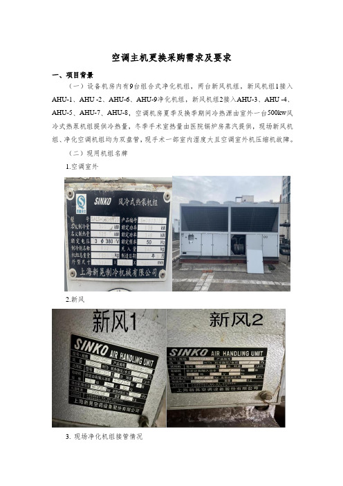
空调主机更换采购需求及要求一、项目背景(一)设备机房内有9台组合式净化机组,两台新风机组,新风机组1接入AHU-1、AHU -2、AHU-6、AHU-9净化机组,新风机组2接入AHU-3、AHU -4、AHU-5、AHU-7、AHU-8,空调机房夏季及换季期间冷热源由室外一台500kw风冷式热泵机组提供冷热量,冬季手术室热量由医院锅炉房蒸汽提供,现场新风机组、净化空调机组均为双盘管,现手术一部室内湿度大且空调室外机压缩机故障。
(二)现用机组名牌1.空调室外2.新风3.现场净化机组接管情况4.机房机组接管图二、改造要求及技术标准(一)本次改造更换新风机组2台,更换七层辅区冷热源,冷热源冬季由供热机房板换提供热量,制冷季冷热源、换季期间空调冷热源由屋面空调机组提供。
现需要对新风机组1、新风机组2、新风管道、送风管更换,室外机、室外管道、阀件、电缆及净化空调机组供回水管支管、阀门、保温及配件进行更换,新机组控制系统安装(控制与原系统进行连接),并对净化机组密封性进行维修。
(二)具体改造要求:1、新风机组1参数(新风量:≥7500m³/h;制冷:≥95kw;制热量:≥80kw;新风预热量:≥10kw;深度除湿:≥5HP;电功率:≥4.5KW 总功率:≥14.5KW ;机外余压:≥450Pa;电源:≥380V);2、新风机组2参数(新风量:≥12000m³/h;制冷:≥140kw;制热量:≥115kw;新风预热量:≥15kw;深度除湿:≥5HP;电功率:≥7.5KW;总功率:≥22.5KW;机外余压≥550Pa;电源:≥380V);3、室外机更换为四台模块式风冷热泵机组(制冷量:≥130kw;制热量:≥132kw)。
4、新风机组段位为预热段、新风段、除湿段、粗效过滤段、中效过滤、亚高效过滤段、表冷段、加热段、出风段。
5、现有室外机机组、基础、管道的拆除。
新设备、设备基础、管道、电缆、线路、控制柜及控制系统的购买与安装。
沃乐夫新风系统如何开关使用说明书
沃乐夫新风系统如何开关使用说明书新风系统是一种净化室内空气的环境优化产品,主要由新风换气机及管道附件组成。
当新风系统工作时,新风换气机将室外的气体进行过滤、净化,然后将干净的空气通过管道输送到室内,同时排出室内污浊的空气,实现空气净化的目的。
新风系统控制器就像一个管家,掌握和控制着新风系统的运行状态。
它可自动对室内二氧化碳浓度、挥发性有机化合物含量以及空气污染指数进行检测,从而调节风机的启停和风速的大小;同时也能有效检测室内温度、湿度,还可分段控制风速启停,不仅节能还为用户创造一个清新自然的环境。
新风系统能够高效的运作,除了产品本身外,还得益于新风系统控制器的使用,新风系统控制器设有手动及自动风量调节功能和滤网使用时间提醒等功能,下面我们一起来了解一下新风系统控制器使用方法。
1、手动风量调节:新风系统控制器电源接通后,过5秒后按开关键,液晶屏出现手动运行模式图标以及风量调节图标,然后按风量切换键,可在高、中、低风量间自由切换。
2、自动风量调节:按新风系统控制器界面的上下键,便进入自动运行模式,并且液晶屏显示自动运行模式图标。
3、滤网使用时间提醒设置:按设置选择键,在液晶屏上会显示“F”,同时过滤时间闪烁;再通过按上或下键选择时间即可。
BS80WCQ 墙外型Split壁式空气调节器操作手册说明书

Manual de instruccionesdel Acondicionador de Airede pared Tipo SplitLea atentamente todo este manualantes de utilizar su nuevo equipo de aire acondicionadoModelo:BS80WCQESPECIFICACIONES DE USO2. Consideraciones variasPreparación antes del funcionamiento1. Consultar al distruibuidor o al especialista para la instalación.2. Colocar el cable en forma correcta.3. No utilizar un cable dañado o que no corresponda.4. No compartir el enchufe de la unidad con otros equipos.5. No utilizar un prolongador eléctrico.6. No prender o apagar el acondicionador de aire tirando del cable.Uso1. La exposición prolongada a las corrientes de aire podría ser perjudicial para su salud. No exponer a las personas, a las mascotas o a las plantas a las corrientes de aire durante un tiempo prolongado.2. Debido a la posibilidad de escasez de oxígeno, ventilar la habitación al utilizar la unidad junto con una calefacción o junto a otros equipos que emitan calor.3. No utilizar el acondicionador de aire con própositos especiales. (ej. Conservación de otros equipos, alimentos, plantas, animales u objetos de arte). Utilizarlo con este próposito podría causar severo deterioro en los mismos.Limpieza y mantenimiento1. Al retirar el filtro no tocar las partes metálicas que posee el acondicionador de aire. Podría lastimarse con los bordes filosos que posee la unidad.2. No utilizar agua para limpiar el interior de la unidad. La exposición al agua podría no aislar la eléctricidad y provocar una descarga eléctrica.3. Aségurese de apagar y desenchufar la unidad al limpiarla.Servicio TécnicoPara repaciones y mantenimiento consulte a servicio técnico autorizado.MODE SMARTTEMP.SUPERTEMP.NOTATodas las ilustraciones de este manual son sólo con fines explicativos. Podrían ser diferentes del acondicionador de aire que usted compró.6. Ajuste de la dirección del flujo de aireAjuste de la dirección de aire• Ajustar la dirección del aire correctamente, de lo contrario podría incomodar o causar temperaturas dispares en la habitación.• Ajustar la rejilla en forma horizontal utilizando el control remoto.• Ajustar la rejilla vertical manualmente.• Ajustar la dirección vertical del aire hacia arriba o hacia abajo (up - down).El acondicionador ajustará automáticamente la dirección vertical del aire de acuerdoa la función utilizada.Para seleccionar la dirección del aireUtilizar esta función cuando la unidad esté en funcionamiento.Presione el botón de control automático de dirección de flujo de aire SWING (Mov. Deflec-tor) en el control remoto para mover la rejilla, luego presione nuevamente hasta que la rejilla alcance la dirección deseada.• Ajustar el flujo de aire vertical a la dirección deseada.• Cuando se enciende la unidad el flujo de aire vertical se programa en la dirección escrita en el microprocesador.Para ajustar la dirección del flujo de aire vertical (izquierda - derecha) Ajustar la rejilla vertical de forma manual utilizando la palanca que se encuentra en la rejilla (esto varía según el modelo). Preste atención de no engancharse los dedos con el ventilador, con la rejilla horizontal o de dañar las rejillas verticales.• Cuando el acondicionador este encendido y la rejilla horizontal esté en posición, mueva la palanca hacia el extremo izquierdo (o derecho, dependiendo del modelo) a la salida de aire deseada.PRECAUCION• El botón de dirección de flujo de aire SWING (Mov.Deflector) será desactivado si el acondicionador de aire se apaga.• No utilizar el acondicionador de aire por largos períodos apuntando hacia abajo en la función frío o de secado. De lo contrario podría producirse condensación en la superficie de la rejilla vertical causando humedad y posible goteo de agua.• No mover la rejilla vertical en forma manual.Siempre utilice el botón de dirección de flujo de aire SWING (Mov.Deflector).• Mover el deflector horizontal manualmente podría producir fallas en el funcionamiento de la unidad. Si no funcionara correctamente el deflector reiniciar la unidad.• Al reiniciar el acondicionador de aire inmediatamente despúes de ser apagado, el deflector horizontal no se moverá durante aproxima damente 10 segundos.El ángulo de apertura de la rejilla horizontal no debe ser muy pequeño, esto podría afectar el funcionamiento de la salida de aire.• No utilizar la unidad con el deflector cerrado.• Cuando se enciende el acondicionador de aire, el deflector puede generar un sonido durante 10 segundos, esto es normal.7. Rendimiento óptimoPara alcanzar un rendimiento óptimo siga estas instrucciones:• Ajuste la dirección del aire correctamente sin que esta esté dirigida directamente a las personas.• Ajuste el valor de temperatura (Se recomienda una temperatura confortable de 22ºC - 25° C). No ajustar la unidad a temperaturas extremas.• Cierre todas las puertas y ventanas cuando utilice las funciones de frío y calor. De no hacerlo el rendimiento se verá disminuído.• Utilice el botón encendido del temporizador TIMER ON (Enc.Auto) para seleccionar la hora en la que quiere que su acondicionador de aire se encienda.• No bloquear la salida de aire de la unidad interior o exterior, el rendimiento puede verse disminuído y el acondicionador podría apagarse.• Limpiar el filtro de aire periodicamente, de no hacerlo el rendimiento dismimuye.• No utilizar la unidad con el deflector horizontal cerrado.Los equipos no están diseñados para trabajar en modo Frío con temperatura exterior menor a los 18º C.Equipos Frío/Calor por bomba de calor: durante el funcionamiento en modo de calor,el equipo absorbe calor del exterior y lo descarga en el ambiente. Si la temperatura exterior es inferior de 0º, la capacidad de calefacción disminuye.NOTANOTA9. Consejos para el funcionamiento1. Protección del acondicionador de aire• Protección del compresor: el compresor no podrá reiniciarse hasta 3 minutos despúesde apagado.• Anti-aire frío (sólo para modelos con ciclo revertido): la unidad está diseñada para no generar aire frío durante la función de calor, cuando la unidad interior se encuentre en las siguientes situaciones:A) Cuando la función calor acaba de iniciarse.B) Descongelamiento.La ventilación se detiene durante la función de descongelamiento (Sólo para los modelos con bomba de calor).• Descongelamiento (Sólo para los modelos con bomba de calor): se puede producir escarcha en la unidad exterior cuando la temperatura exterior es muy baja y la humedad es muy alta, esto afectará el funcionamiento de la unidad.Bajo estas condiciones, el acondicionador de aire detendrá la función calor y comenzará la función de descongelamiento.El tiempo de descongelamiento puede variar entre 6 y 10 minutos según la temperatura exterior y la cantidad de escarcha acumulada en la unidad exterior.2. Un humo blanco proviene de la unidad interior• Este humo puede ser generado a la gran diferencia de temperatura entre la salida y la entrada de aire en la función frío en una habitación donde haya mucha humedad.• También puede ser generado por la humedad que produce la función de descongelamiento cuando el acondicionador de aire se reinicia en la función calor.3. Ruido en el acondicionador de aire• Se puede escuchar un silbido cuando el compresor está funcionando o cuando acabade apagarse. Este sonido es el refr igerante al fluir o al detenerse.• Se puede escuchar un chirrido cuando el compresor está funcionando o cuando acaba de apagarse. Esto es causado por la expansión por el calor o la contracción por el frío de las piezas plásticas de la unidad debido al cambio de temperatura.• Podría escucharse un sonido cuando se coloca nuevamente la rejilla en su posición original.4. Podría gotear agua en la superficie de la unidad interior cuando se refrigera con una humedad muy alta (cuando la humedad sea mayor al 80%).Ajustar la rejilla horizontal para que la salida de aire sea óptima y seleccione la función de ventilación alta.5. Función de reinicio autómaticoSi durante el funcionamiento del equipo este dejase de trabajar por falta de fluído eléctrico, no será necesario accionar nuevamente el control del equipo. Una vez que se reponga la alimentación, el equipo se pondrá en marcha en las mismas condiciones en que se encontraba antes del corte de energía.6. Relámpagos o cables de télefono que funcionen próximos podrían causar un mal funcio-namiento de la unidadDesconectar la unidad y luego reiniciarla.Presionar el botón ON/OFF (SI/NO) en el control remoto para realizar esta operación.ESPECIFICACIONES DE INSTALACIÓN• Asegúrese de colocar la manguera de drenaje más abajo del equipo. Si se coloca muy alta podría • Colocar la manguera de drenaje inclinada hacia abajo para que el agua condensada drene.Realizar el trabajo de abocardado tal como se indica en la ilustración.。
沃尔夫-弗斯产品说明书:NCN3-F31-N4-V16-V16 感应传感器

12R e l e a s e d a t e : 2 0 1 6 -1 2 -0 1 1 3 : 5 4 D a t e o f i s s u e : 2 0 1 6 -1 2 -0 1 2 2 3 9 6 1 _ e n g . x m lElectrical Connection3R e l e a s e d a t e : 2016-12-01 13:54D a t e o f i s s u e : 2016-12-01223961_e n g .x m lInstructionManual electrical apparatus for hazardous areas Device category 1Gfor use in hazardous areas with gas, vapour and mist EC-T ype Examination CertificateCE marking ATEX marking ¬ II 1G Ex ia IIC T6…T1 G aStandards EN 60079-0:2012, EN 60079-11:2012, EN 60079-26:2007 Ignition protection "Intrinsic safety"Use is restricted to the following stated conditions Appropriate typeNCN3-F31.-N4...Effective internal inductivity C i ≤ 100 nF A cable length of 10 m is considered. The value is applicable for one sensor circuit.Effective internal inductance L i≤ 100 µH A cable length of 10 m is considered. The value is applicable for one sensor circuit.G eneralThe apparatus has to be operated according to the appropriate data in the data sheet and in this instruction manual.The EU-type examination certificate has to be observed. The special conditions must be adhered to!The ATEX directive and therefore the EU-type examination certificates apply in gen-eral only to the use of electrical apparatus under atmospheric conditions.The use in ambient temperatures of > 60 °C was tested with regard to hot surfaces by the mentioned certification authority.If the equipment is not used under atmospheric conditions, a reduction of the permis-sible minimum ignition energies may have to be taken into consideration.Ambient temperatureThe temperature ranges, according to temperature class, are given in the EC-T ype Examination Certificate. The maximum permissible ambient temperature of the data sheet must be noted, in addition, the lower of the two values must be maintained. Note: Use the temperature table for category 1 The 20 % reduction in accordance with EN 1127-1:2007 has already been accounted for in the tempera-ture table for category 1.Installation, commissioningLaws and/or regulations and standards governing the use or intended usage goal must be observed.The intrinsic safety is only assured in connection with an appropriate related appara-tus and according to the proof of intrinsic safety.The associated apparatus must satisfy the requirements of category ia.Due to the possible danger of ignition, which can arise due to faults and/or transient currents in the equipotential bonding system, galvanic isolation of the power supply and signal circuit is preferable. Associated apparatus without electrical isolation must only be used if the appropriate requirements of IEC 60079-14 are met.Install the device in such a way that the resin surface is not exposed to mechanical hazards.Maintenance No changes can be made to apparatus, which are operated in hazardous areas.Repairs to these apparatus are not possible.Special conditionsProtection from mechanical danger When used in the temperature range below -20 °C the sensor should be protected from knocks by the provision of an additional housing.Electrostatic chargeAdditional requirements for gas group IIC. Avoid electrostatic charges that can cause electrostatic discharge when installing or operating the device. Information on elec-trostatic hazards can be found in the technical specification IEC/TS 60079-32-1.4Releasedate:216-12-113:54Dateofissue:216-12-1223961_eng.xml Instruction Manual electrical apparatus for hazardous areasDevice category 2G for use in hazardous areas with gas, vapour and mistEC-T ype Examination CertificateCE markingATEX marking ¬ II 1G Ex ia IIC T6…T1 G aStandards EN 60079-0:2012, EN 60079-11:2012Ignition protection "Intrinsic safety"Use is restricted to the following stated conditionsAppropriate type NCN3-F31.-N4...Effective internal inductivity C i≤ 100 nF ; a cable length of 10 m is considered. The value is applicable for one sen-sor circuit.Effective internal inductance L i≤ 100 µH ; a cable length of 10 m is considered. The value is applicable for one sen-sor circuit.G eneral The apparatus has to be operated according to the appropriate data in the data sheetand in this instruction manual. The EU-type examination certificate has to beobserved. The special conditions must be adhered to!The ATEX directive and therefore the EU-type examination certificates apply in gen-eral only to the use of electrical apparatus under atmospheric conditions.The use in ambient temperatures of > 60 °C was tested with regard to hot surfacesby the mentioned certification authority.If the equipment is not used under atmospheric conditions, a reduction of the permis-sible minimum ignition energies may have to be taken into consideration.Maximum permissible ambient temperature T amb The temperature ranges, according to temperature class, are given in the EC-T ypeExamination Certificate. The maximum permissible ambient temperature of thedata sheet must be noted, in addition, the lower of the two values must bemaintained.Installation, commissioning Laws and/or regulations and standards governing the use or intended usage goalmust be observed. The intrinsic safety is only assured in connection with an appro-priate related apparatus and according to the proof of intrinsic safety. Install thedevice in such a way that the resin surface is not exposed to mechanical hazards.Maintenance No changes can be made to apparatus, which are operated in hazardous areas.Repairs to these apparatus are not possible.Special conditionsProtection from mechanical danger When used in the temperature range below -20 °C the sensor should be protectedfrom knocks by the provision of an additional housing.5R e l e a s e d a t e : 2016-12-01 13:54D a t e o f i s s u e : 2016-12-01223961_e n g .x m lInstructionManual electrical apparatus for hazardous areas Device category 3G (ic) for use in hazardous areas with gas, vapour and mist CertificateCE marking ATEX marking ¬ II 3G Ex ic IIC T6…T1 GcStandardsEN 60079-0:2012, EN 60079-11:2012 Ignition protection category "ic" Use is restricted to the following stated conditions Effective internal inductivity C i ≤ 100 nF ; A cable length of 10 m is considered.The value is applicable for one sensor circuit.Effective internal inductance L i≤ 100 µH ; A cable length of 10 m is considered.The value is applicable for one sensor circuit.G eneralThe apparatus has to be operated according to the appropriate data in the data sheet and in this instruction manual. The data stated in the data sheet are restricted by this operating instruction!The special conditions must be observed!The ATEX Directive applies only to the use of apparatus under atmospheric condi-tions.If you use the device outside atmospheric conditions, consider that the permissible safety parameters should be reduced.Installation, commissioningLaws and/or regulations and standards governing the use or intended usage goal must be observed. The sensor must only be operated with energy-limited circuits, which satisfy the requirements of IEC 60079-11. The explosion group depends on the connected, energy-limited power supply circuits.The maximum values of the connected, energy-limited valve circuits, must be observed. Install the device in such a way that the resin surface is not exposed to mechanical hazards.Maintenance No changes can be made to apparatus, which are operated in hazardous areas.Repairs to these apparatus are not possible.Special conditionsMaximum permissible ambient temperature T Umax at Ui = 20 V Each sensor circuit can be operated with the stated maximum values and with simul-taneous operation of the valve circuits. for Pi=34 mW, Ii=25 mA, T6 70 °C (158 °F) for Pi=34 mW, Ii=25 mA, T5 70 °C (158 °F) for Pi=34 mW, Ii=25 mA, T4-T1 70 °C (158 °F) for Pi=64 mW, Ii=25 mA, T6 70 °C (158 °F) for Pi=64 mW, Ii=25 mA, T5 70 °C (158 °F) for Pi=64 mW, Ii=25 mA, T4-T1 70 °C (158 °F) for Pi=169 mW, Ii=52 mA, T6 67 °C (152.6 °F) for Pi=169 mW, Ii=52 mA, T5 70 °C (158 °F) for Pi=169 mW, Ii=52 mA, T4-T1 70 °C (158 °F)Maximum values of the valve circuit U i = 32 V; I i = 240 mA; C i = 10 nF; L i = 20 µHThe values are applicable to each valve circuit. A cable length of 10 m is taken into account.Protection from mechanical dangerThe sensor must not be mechanically damaged.When used in the temperature range below -20 °C the sensor should be protected from knocks by the provision of an additional housing.Connection partsThe connection parts are to be installed, such that a minimum protection class of IP20 is achieved, in accordance with IEC 60529.。
智能性房屋呼吸系统:普米欧全智能高效新风热交换机组
智能性房屋呼吸系统:普米欧全智能高效新风热交换机组佚名
【期刊名称】《中国建设信息》
【年(卷),期】2010(000)011
【摘要】上海协佳楼宇科技有限公司日前推出意大利沃特斯低能耗新风系统,VORTICEPROMETEOHR400普米欧全智能高效新风热交换机组。
该机组内含二氧化碳浓度探测器,符合绿色节能LEED认证,无线遥控面板。
随时监测二氧化碳浓度及温湿度,先进的节能科技使居室能最大化节省制冷和制热量。
【总页数】1页(P56)
【正文语种】中文
【中图分类】TU995
【相关文献】
1.基于排风冷凝热回收技术的高效除湿新风机组 [J], 张国华;许亚兵
2.浅谈DHE111型高效节能热交换机组的独特优势 [J], 曲小秋
3.除霾杀菌技术的全热交换新风机组应用设计 [J], 刘莹;杨力;陈佑杨
因版权原因,仅展示原文概要,查看原文内容请购买。
基站节能新风系统(TLK)

基站节能新风系统TLKS-SPF方案书目录目录 (1)一、应用背景 01.1.基站电费支出增大 (7)1.2.基站空调电费支出所占比例较大 (7)1.3.基站空调用电浪费现象较为严重 (8)二、原理、组成、工作流程及参数 (9)2.1.系统原理 (9)2.2.系统组成 (9)2.3.系统工作流程 (10)三、系统设备示意图(图片仅供参考,具体以实物为准) (11)3.1.主控机箱 ...................................................................................................... 错误!未定义书签。
3.2.进风箱 (13)3.3.排风箱 (14)3.4.室内温度探测器 (14)3.5.室外温、湿度探测器 (15)3.6.室外灰尘探测器 (15)3.7.交流互感器 (16)3.8.交流接触器 (16)3.9.滤尘装置(中高效过滤器) (17)3.10.防雨透风口 (18)3.11.网管连接线 (18)3.12.报警器 (18)四、主控板的结构 (3)五、主要技术性能 (4)六、主要技术指标 (6)七、系统设置及操作说明 (7)7.1.系统设置的参数 (7)7.2.系统运行逻辑 (8)7.3.主控面板指示 (8)7.4.系统操作说明 (8)八、基站智能通风系统的设备组成清单 (13)九、售后服务计划及承诺 (14)9.1.壹年免费维修,终身维护 (14)9.2.最快速的抢修服务 (14)9.3.保证系统不间断运行 (14)9.4.终身跟踪服务和长期技术支持 (14)9.5.完善的培训体制 (14)9.6.用户意见反馈 (14)第2页科技立足创新致远公司简介深圳市特力康科技有限公司位于深圳市龙岗区坂田,西邻华为,东接布吉。
公司有研发中心、生产中心、销售中心、财务中心等执行机构。
公司坚持创新研发和市场销售并重的理念,不能有订单的产品不是产品,产品没有创新是特力康人的耻辱,做出对世界有用的产品。
01-XRow系列列间空调-手册-说明书

- 1、下载文档前请自行甄别文档内容的完整性,平台不提供额外的编辑、内容补充、找答案等附加服务。
- 2、"仅部分预览"的文档,不可在线预览部分如存在完整性等问题,可反馈申请退款(可完整预览的文档不适用该条件!)。
- 3、如文档侵犯您的权益,请联系客服反馈,我们会尽快为您处理(人工客服工作时间:9:00-18:30)。
沃特斯新风主机
怎么选择新风主机
1、选择知名品牌(是否是原装进口,出产地证明、报关单、有何荣誉);
2、听噪音(这个方法是最简单的,进口的产品噪音一般较低,不影响睡眠);
3、看外形(最好小巧,因为我们要考虑是否会影响到吊顶高度,此外可以看看做工是否精细);
4、了解使用寿命(原装进口机使用寿命较长,不会用不了几年就坏掉了,成了多余的废品,建议约定质保期);
5、看能耗(如果瓦数过高,那就成了电老虎,能耗指标一定要注意);
6、感受风量(用手就能感觉到了,这个方法挺简单);
沃特斯(VORTICE)灵诺LINEO125突出优势:新风系统主力机型
1、雅典奥运会场馆指定通风产品;
2、多次荣获欧洲工业设计大奖——世界首创无螺丝搭扣链接,轻松拆卸;
3、专利双层保护外壳,清洗、维护相当方便;
4、能耗极低,最大风量365M3/h的风机,高速能耗仅33瓦,低速能耗更是低至25瓦,24小时运行最多仅耗电0.79度(这一点业主会非常喜欢);
5、选用双速长寿命高效静音马达,调节更方便,噪音更低(高速运行时最大噪音不超过33分贝),支持三万小时不间断连续运行;
6、极大地优化了通风机内部的空间利用,以大幅减少产品的总体尺寸,本款主机的安装高度可低至189mm,堪称全球最小安装空间的管道风机;
7、IP×4防水等级,马达自带过载保护,可在60℃温度/95%相对湿度的恶劣环境下工作;
8、沃特斯(VORTICE)产品为所有通风机里最高级别的UL98-VO级高阻燃材料标准(美国保险协会标准),可完全杜绝主机长期在吊顶内运行产生高温而燃烧的风险;
9、安装后第一年可提供两次免费系统维护和清洗风口服务,让您轻轻松松享受新风;
10、基于对沃特斯(VORTICE)品质的绝对自信,我们承诺:两年内非人为因素损坏,无条件更换新机。
8种型号:
LINEO 100 ES (直径100mm)
LINEO 100 QES (直径100mm)
LINEO 125 ES (直径125mm)
LINEO 150 ES (直径150mm)
LINEO 160 ES (直径160mm)
LINEO 200 ES (直径200mm)
LINEO 250 ES (直径250mm)
LINEO 315 QES (直径315mm)。
