GS3010中文资料
晟皋SG3010数字式接地电阻测试仪

SG3010数字式接地电阻测试仪使用说明书上海晟皋电气科技有限公司目录一.安全规则及注意事项 (2)二.简介 (2)三.量程及精度 (3)四.技术规格 (3)五.仪表结构 (4)六.测量原理 (5)七.功能速查 (5)八.操作方法 (6)1.开关机 (6)2.电池电压检查 (6)3.接地电压测量 (6)4.线阻校验 (6)5.接地电阻精密测量 (7)6.简易法测量接地电阻 (7)7.背光控制 (8)8.报警设置 (8)9.数据锁定/存储 (8)10.数据查阅/删除 (9)九.电池说明 (9)十.装箱单 (10)一.安全规则及注意事项感谢您购买了本公司数字式接地电阻测试仪,在你初次使用该仪器前,为避免发生可能的触电或人身伤害,请一定:详细阅读并严格遵守本手册所列出的安全规则及注意事项。
任何情况下,使用本仪表应特别注意安全。
●本仪表根据IEC61010安全规格进行设计、生产、检验。
●任何情况下,使用本仪表应特别注意安全。
●测量时,移动电话等高频信号发生器请勿在仪表旁使用,以免引起误差。
●注意本仪表机身的标贴文字及符号。
●使用前应确认仪表及附件完好,仪表、测试线绝缘层无破损、无裸露、无断线才能使用。
●测量过程中,严禁接触裸露导体及正在测量的回路。
●确认导线的连接插头已紧密地插入仪表接口内。
●请勿在测试端与接口之间施加超过600V的交流电压或直流电压,否则可能损坏仪表。
●请勿在易燃性场所测量,火花可能引起爆炸。
●仪表在使用中,机壳或测试线发生断裂而造成金属外露时,请停止使用。
●请勿于高温潮湿,有结露的场所及日光直射下长时间放置和存放仪表。
●给仪表更换电池时,请确认测试线已移离仪表,仪表处于关机状态。
●仪表显示电池电压低符号“”,应及时更换电池。
●注意本仪表所规定的测量范围及使用环境。
●使用、拆卸、校准、维修本仪表,必须由有授权资格的人员操作。
●由于本仪表原因,继续使用会带来危险时,应立即停止使用,并马上封存,由有●全操作。
Leica GS10 GS15 用户手册

Leica GS10/GS15用户手册版本 3.0中文2GS10/GS15, 简介简介购买恭贺您购买了Leica GS10/GS15。
本手册包括了重要的安全指南,可指导您安全地安装并使用仪器。
详情请参见"5 安全指南"。
请您在使用本产品之前仔细阅读用户手册。
仪器标识仪器的型号和序列号标注在仪器标签上。
请将仪器型号和序列号填写在下面。
当您需要与经销商或Leica Geosystems 授权的维修部门联系时,将会用到这些信息。
符号本手册中所使用的符号有如下的含义:类型:_______________序列号:_______________类型说明ƽ危险指出一个即将来临的危险情形,如果不加以避免,将导致死机或严重损害。
GS10/GS15, 简介3商标•Windows 是微软公司(Microsoft Corporation)在美国和其他国家的注册商标。
•Bluetooth 是蓝牙标准化组织(Bluetooth SIG, Inc)的注册商标。
•SD 是 SD 卡协会的注册商标。
其他商标所有权归各自拥有者。
本手册的有效性本手册用于GS10/GS15。
ƽ警告表示潜在的或操作不当所致的危险情况,如果不加以避免,将将造成伤亡或严重损害。
ƽ注意表示潜在的或操作不当所导致的危害,如果不加以避免,将导致轻微的人身伤害或明显的设备、经济损失和环境的损害。
)表示在实际使用中必须注意的重要章节,以便能够正确、有效地使用该仪器。
类型说明4GS10/GS15, 简介可用文档关于GS10/GS15可查阅下述所有文档/软件资源:•Leica Viva Series DVD•https://myWorld@Leica Geosystems (https://)提供许多服务,信息和培训材料。
通过直接访问 myWorld,您在任何时候(7天×24小时)都可以获取相关服务。
它能提高您的工作效率,保证您和您的仪器能及时从Leica Geosystems获取最新的信息。
戴尔 OptiPlex 3010 小型计算机 用户手册说明书

Dell OptiPlex 3010 小型计算机用户手册管制型号: D04S管制类型: D04S001注、小心和警告注: “注”表示可以帮助您更好地使用计算机的重要信息。
小心: “小心”表示可能会损坏硬件或导致数据丢失,并说明如何避免此类问题。
警告: “警告”表示可能会造成财产损失、人身伤害甚至死亡。
© 2013 Dell Inc.本文中使用的商标: Dell™、 DELL 徽标、 Dell Precision™、 Precision ON™、ExpressCharge™、 Latitude™、Latitude ON™、 OptiPlex™、 Vostro™和 Wi-Fi Catcher™是 Dell Inc. 的商标。
Intel®、 Pentium®、 Xeon®、 Core™、 Atom™、 Centrino®和 Celeron®是 Intel Corporation 在美国和/或其他国家或地区的注册商标。
AMD®是注册商标, AMD Opteron™、 AMD Phenom™、AMD Sempron™、 AMD Athlon™、 ATI Radeon™和 ATI FirePro™是 Advanced Micro Devices, Inc. 的商标。
Microsoft®、 Windows®、 MS-DOS®、 Windows Vista®、Windows Vista 开始按钮和 Office Outlook®是 Microsoft Corporation 在美国和/或其他国家或地区的注册商标。
Blu-ray Disc™是 Blu-ray Disc Association (BDA) 拥有的商标,经其许可在磁盘和播放器上使用。
Bluetooth®文字标记是 Bluetooth® SIG, Inc. 拥有的注册商标,Dell Inc. 经其许可使用这些标记。
Dell Inspiron N3010 服务手册说明书
Dell™ Inspiron™ N3010 服务手册注、小心和警告本说明文件中的信息如有更改,恕不另行通知。
© 2010 Dell Inc. 版权所有,翻印必究。
未经 Dell Inc. 书面许可,严禁以任何形式复制这些材料。
在此文本中使用的商标:Dell 和 DELL 徽标是 Dell Inc. 的商标;Bluetooth 是 Bluetooth SIG, Inc. 拥有的注册商标,由 Dell 公司依许可证使用;Microsoft 和 Windows 是 Microsoft Corporation 在美国和/或其它国家或地区的商标或注册商标。
本说明文件中述及的其它商标和商品名称是指拥有相应标记和名称的公司或其制造的产品。
Dell Inc. 对不属于自己的商标和商品名称不拥有任何专有权益。
管制型号:P10S 系列管制类型:P10S0012010 年 3 月 Rev. A00开始之前电池内存模块护盖内存模块键盘掌垫部件电源按钮板采用 Bluetooth ® 无线技术的内部模块显示屏摄像头模块处理器散热器风扇 中心控制护盖 VGA 连接器板 系统板 硬盘驱动器 处理器散热器 处理器模块 无线小型插卡 币形电池 扬声器 刷新 BIOS注:“注”表示可以帮助您更好地使用计算机的重要信息。
小心:“小心”表示如果不遵循说明,有可能会损坏硬件或导致数据丢失。
警告:“警告”表示可能会造成财产损失、人身伤害甚至死亡。
1 电池释放闩锁23 电池锁定闩锁返回目录页面开始之前Dell™ Inspiron™ N3010 服务手册建议工具关闭计算机电源拆装计算机内部组件之前本手册提供卸下和安装计算机中组件的步骤。
除非另有说明,否则将假设在执行每个过程时均满足以下条件:l您已经执行了关闭计算机电源和拆装计算机内部组件之前中的步骤。
l您已经阅读了计算机附带的安全信息。
l 以相反顺序执行拆卸步骤可以装回组件或安装单独购买的组件。
PMEG3010EJ,115;PMEG3010EH,115;中文规格书,Datasheet资料
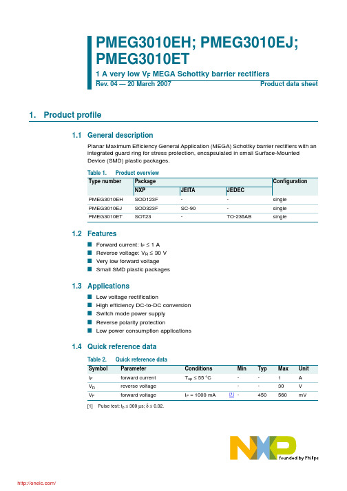
Marking code[1] AA AK *AV
PMEG3010EH_EJ_ET_4
Product data sheet
/
Rev. 04 — 20 March 2007
© NXP B.V. 2007. All rights reserved.
2 of 11
NXP Semiconductors
Conditions in free air
PMEG3010EJ
PMEG301esistance from junction to solder point
PMEG3010EH PMEG3010EJ PMEG3010ET
Min Typ Max Unit
[1]
Rev. 04 — 20 March 2007
© NXP B.V. 2007. All rights reserved.
4 of 11
NXP Semiconductors
PMEG3010EH/EJ/ET
1 A very low VF MEGA Schottky barrier rectifiers
103 IF (mA)
3. Ordering information
Simplified outline Symbol
[1]
1
2
001aab540
1
2
sym001
3
1
2
3
1
2 n.c.
006aaa436
Table 4. Ordering information
Type number Package
Name
Description
[4] Soldering point of cathode tab.
LT3010EMS8E-5中文资料
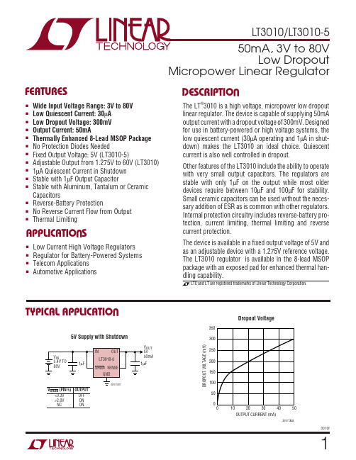
(Note 1)IN Pin Voltage................................................... ±80V OUT Pin Voltage ............................................... ±60V IN to OUT Differential Voltage........................... ±80V ADJ Pin Voltage.................................................. ±7V SHDN Pin Input Voltage ................................... ±80V Output Short-Circuit Duration..................... Indefinite Storage Temperature Range............ –65°C to 150°C Operating Junction Temperature Range(Notes 3, 10, 11)......................... –40°C to 125°C Lead Temperature (Soldering, 10 sec)............ 300°C*SENSE FOR LT3010-5, ADJ FOR LT3010T JMAX = 125°C, θJA = 40°C/W, θJC = 16°C/W †SEE APPLICATIONS INFORMATION SECTION.EXPOSED PAD IS GND (MUST BE SOLDERED TO PCB)†MEASURED AT BOTTOM PADORDER PART NUMBER MS8 PART MARKINGLT3010EMS8E LT3010EMS8E-5LTZF LTAEFABSOLUTE AXI U RATI GSW W WU PACKAGE/ORDER I FOR ATIOU U WELECTRICAL CHARACTERISTICSConsult LTC Marketing for parts specified with wider operating temperature ranges.1234OUTSENSE/ADJ*NC GND8765IN NC NC SHDNTOP VIEWMS8E PACKAGE 8-LEAD PLASTIC MSOPPARAMETER CONDITIONS MIN TYP MAX UNITSMinimum Input VoltageLT3010I LOAD = 50mAq34V Regulated Output Voltage (Note 3)LT3010-5V IN = 5.5V, I LOAD = 1mA4.9255.000 5.075V 6V < V IN < 80V, 1mA < I LOAD < 50mA q 4.850 5.000 5.150V ADJ Pin Voltage LT3010V IN = 3V, I LOAD = 1mA1.258 1.275 1.292V (Notes 2,3)4V < V IN < 80V, 1mA < I LOAD < 50mA q 1.2371.275 1.313V Line Regulation LT3010-5∆V IN = 5.5V to 80V, I LOAD = 1mA q 315mV LT3010 (Note 2)∆V IN = 3V to 80V, I LOAD = 1mA q 313mV Load RegulationLT3010-5V IN = 6V, ∆I LOAD = 1mA to 50mA 2550mV V IN = 6V, ∆I LOAD = 1mA to 50mA q90mV LT3010 (Note 2)V IN = 4V, ∆I LOAD = 1mA to 50mA 1020mV V IN = 4V, ∆I LOAD = 1mA to 50mAq32mV Dropout Voltage I LOAD = 1mA 100150mV V IN = V OUT(NOMINAL)I LOAD = 1mA q190mV (Notes 4, 5)I LOAD = 10mA 200260mV I LOAD = 10mA q350mV I LOAD = 50mA 300370mV I LOAD = 50mAq 550mV GND Pin Current I LOAD = 0mA q 3060µA V IN = V OUT(NOMINAL)I LOAD = 1mA q 100180µA (Notes 4, 6)I LOAD = 10mA q 400700µA I LOAD = 50mAq1.8 3.3mA Output Voltage Noise C OUT = 10µF, I LOAD = 50mA, BW = 10Hz to 100kHz 100µV RMSADJ Pin Bias Current (Note 7)50100nA Shutdown Threshold V OUT = Off to On 1.32V V OUT = On to Off 0.30.8V SHDN Pin Current V SHDN = 0V 0.52µA (Note 8)V SHDN = 6V 0.10.5µA Quiescent Current in ShutdownV IN = 6V, V SHDN = 0V15µAThe q denotes specifications which apply over the full operating temperature range, otherwise specifications are at T J = 25°C.C OUT = 1µF1ms/DIV3010 G25 I L = 50mAThe LT3010 series regulators have internal thermal limit-ing designed to protect the device during overload condi-tions. For continuous normal conditions the maximum junction temperature rating of 125°C must not be ex-ceeded. It is important to give careful consideration to all sources of thermal resistance from junction to ambient.Additional heat sources mounted nearby must also be considered.For surface mount devices, heat sinking is accomplished by using the heat spreading capabilities of the PC board and its copper traces. Copper board stiffeners and plated through-holes can also be used to spread the heat gener-ated by power devices.The following table lists thermal resistance for several different board sizes and copper areas. All measurements were taken in still air on 3/32" FR-4 board with one ounce copper.Table 1. Measured Thermal ResistanceCOPPER AREA THERMAL RESISTANCE TOPSIDE BACKSIDE BOARD AREA (JUNCTION-TO-AMBIENT)2500 sq mm 2500 sq mm 2500 sq mm 40°C/W 1000 sq mm 2500 sq mm 2500 sq mm 45°C/W 225 sq mm 2500 sq mm 2500 sq mm 50°C/W 100 sq mm2500 sq mm2500 sq mm62°C/WThe thermal resistance junction-to-case (θJC ), measured at the exposed pad on the back of the die, is 16°C/W.Continuous operation at large input/output voltage differ-entials and maximum load current is not practical due to thermal limitations. Transient operation at high input/output differentials is possible. The approximate thermal time constant for a 2500sq mm 3/32" FR-4 board withmaximum topside and backside area for one ounce copper is 3 seconds. This time constant will increase as more thermal mass is added (i.e. vias, larger board, and other components).For an application with transient high power peaks, aver-age power dissipation can be used for junction tempera-ture calculations as long as the pulse period is significantly less than the thermal time constant of the device and board.Calculating Junction TemperatureExample 1: Given an output voltage of 5V, an input voltage range of 24V to 30V, an output current range of 0mA to 50mA, and a maximum ambient temperature of 50°C,what will the maximum junction temperature be?The power dissipated by the device will be equal to:I OUT(MAX) • (V IN(MAX) – V OUT ) + (I GND • V IN(MAX))where:I OUT(MAX) = 50mA V IN(MAX) = 30VI GND at (I OUT = 50mA, V IN = 30V) = 1mA So:P = 50mA • (30V – 5V) + (1mA • 30V) = 1.28W The thermal resistance will be in the range of 40°C/W to 62°C/W depending on the copper area. So the junction temperature rise above ambient will be approximately equal to:1.31W • 50°C/W = 65.5°CAPPLICATIO S I FOR ATIOW UUU113010fAPPLICATIO S I FOR ATIOW UUU The maximum junction temperature will then be equal to the maximum junction temperature rise above ambient plus the maximum ambient temperature or:T JMAX = 50°C + 65.5°C = 115.5°CExample 2: Given an output voltage of 5V, an input voltage of 48V that rises to 72V for 5ms(max) out of every 100ms,and a 5mA load that steps to 50mA for 50ms out of every 250ms, what is the junction temperature rise above ambi-ent? Using a 500ms period (well under the time constant of the board), power dissipation is as follows:P1(48V in, 5mA load) =5mA • (48V – 5V)+ (200µA • 48V) = 0.23W P2(48V in, 50mA load) = 50mA • (48V – 5V)+ (1mA • 48V) = 2.20W P3(72V in, 5mA load) =5mA • (72V – 5V)+ (200µA • 72V) = 0.35W P4(72V in, 50mA load) =50mA • (72V – 5V)+ (1mA • 72V) = 3.42W Operation at the different power levels is as follows:76% operation at P1, 19% for P2, 4% for P3, and1% for P4.P EFF = 76%(0.23W) + 19%(2.20W) + 4%(0.35W)+ 1%(3.42W) = 0.64WWith a thermal resistance in the range of 40°C/W to 62°C/W, this translates to a junction temperature rise above ambient of 26°C to 38°C.Protection FeaturesThe LT3010 incorporates several protection features which make it ideal for use in battery-powered circuits. In addi-tion to the normal protection features associated with monolithic regulators, such as current limiting and ther-mal limiting, the device is protected against reverse-input voltages, and reverse voltages from output to input.Current limit protection and thermal overload protection are intended to protect the device against current overload conditions at the output of the device. For normal opera-tion, the junction temperature should not exceed 125°C.The input of the device will withstand reverse voltages of 80V. Current flow into the device will be limited to less than 6mA (typically less than 100µA) and no negative voltage will appear at the output. The device will protect both itself and the load. This provides protection against batteries which can be plugged in backward.The ADJ pin of the adjustable device can be pulled above or below ground by as much as 7V without damaging the device. If the input is left open circuit or grounded, the ADJ pin will act like an open circuit when pulled below ground,and like a large resistor (typically 100k) in series with a diode when pulled above ground. If the input is powered by a voltage source, pulling the ADJ pin below the refer-ence voltage will cause the device to try and force the current limit current out of the output. This will cause the output to go to a unregulated high voltage. Pulling the ADJ pin above the reference voltage will turn off all output current.121314Information furnished by Linear Technology Corporation is believed to be accurate and reliable. However, no responsibility is assumed for its use. Linear Technology Corporation makes no represen-tation that the interconnection of its circuits as described herein will not infringe on existing patent rights.15PART NUMBER DESCRIPTION COMMENTSLT1020125mA, Micropower Regulator and Comparator V IN: 4.5V to 36V, V OUT = 2.5V, V DO = 0.4V, I Q = 40µA, I SD = 40µA,Comparator and Reference, Class B Outputs, S16, PDIP14 PackagesLT1120/LT1120A125mA, Micropower Regulator and Comparator V IN: 4.5V to 36V, V OUT = 2.5V, V DO = 0.4V, I Q = 40µA, I SD = 10µA,Comparator and Reference,Logic Shutdown, Ref Sources and Sinks 2/4mA,S8, N8 PackagesLT1121/150mA, Micropower, LDO V IN: 4.2V to 30/36V, V OUT = 3.75V, V DO = 0.42V, I Q = 30µA, I SD = 16µA,LT1121HV Reverse Battery Protection, SOT-223, S8, Z PackagesLT1129700mA, Micropower, LDO V IN: 4.2V to 30V, V OUT = 3.75V, V DO = 0.4V, I Q = 50µA, I SD = 16µA,DD, S0T-223, S8,TO220-5, TSSOP20 PackagesLT161625V, 500mA (I OUT), 1.4MHz, High Efficiency V IN: 3.6V to 25V, V OUT = 1.25V, I Q = 1.9mA, I SD = <1µA, ThinSOT Package Step-Down DC/DC ConverterLT167660V, 440mA (I OUT), 100kHz, High Efficiency V IN: 7.4V to 60V, V OUT = 1.24V, I Q = 3.2mA, I SD = 2.5µA, S8 Package Step-Down DC/DC ConverterLT1761100mA, Low Noise Micropower, LDO V IN: 1.8V to 20V, V OUT = 1.22V, V DO = 0.3V, I Q = 20µA, I SD = <1µA,Low Noise < 20µV RMS P-P, Stable with 1µF Ceramic Capacitors, ThinSOT Package LT1762150mA, Low Noise Micropower, LDO V IN: 1.8V to 20V, V OUT = 1.22V, V DO = 0.3V, I Q = 25µA, I SD = <1µA,Low Noise < 20µV RMS P-P, MS8 PackageLT1763500mA, Low Noise Micropower, LDO V IN: 1.8V to 20V, V OUT = 1.22V, V DO = 0.3V, I Q = 30µA, I SD = <1µA,Low Noise < 20µV RMS P-P, S8 PackageLT1764/LT1764A3A, Low Noise, Fast Transient Response, LDO V IN: 2.7V to 20V, V OUT = 1.21V, V DO = 0.34V, I Q = 1mA, I SD = <1µA,Low Noise < 40µV RMS P-P, “A” Version Stable with Ceramic Capacitors,DD, TO220-5 PackagesLT176660V, 1.2A (I OUT), 200kHz, High Efficiency V IN: 5.5V to 60V, V OUT = 1.20V, I Q = 2.5mA, I SD = 25µA, TSSOP16/E Package Step-Down DC/DC ConverterLT177640V, 550mA (I OUT), 200kHz, High Efficiency V IN: 7.4V to 40V, V OUT = 1.24V, I Q = 3.2mA, I SD = 30µA, N8, S8 Packages Step-Down DC/DC ConverterLT1934/300mA/60mA, (I OUT), Constant Off-Time, High90% Efficiency, V IN: 3.2V to 34V, V OUT = 1.25V, I Q = 14µA, I SD = <1µA,LT1934-1Efficiency Step-Down DC/DC Converter ThinSOT PackageLT195660V, 1.2A (I OUT), 500kHz, High Efficiency V IN: 5.5V to 60V, V OUT = 1.20V, I Q = 2.5mA, I SD = 25µA, TSSOP16/E Package Step-Down DC/DC ConverterLT1962300mA, Low Noise Micropower, LDO V IN: 1.8V to 20V, V OUT = 1.22V, V DO = 0.27V, I Q = 30µA, I SD = <1µA,Low Noise < 20µV RMS P-P, MS8 PackageLT1963/LT1963A 1.5A, Low Noise, Fast Transient Response, LDO V IN: 2.1V to 20V, V OUT = 1.21V, V DO = 0.34V, I Q = 1mA, I SD = <1µA,Low Noise < 40µV RMS P-P, “A” Version Stable with Ceramic Capacitors,DD, TO220-5, S0T-223, S8 PackagesLT1964200mA, Low Noise Micropower, Negative LDO V IN: –0.9V to –20V, V OUT = –1.21V, V DO = 0.34V, I Q = 30µA, I SD = 3µA,Low Noise < 30µV RMS P-P, Stable with Ceramic Capacitors, ThinSOT Package RELATED PARTSLinear Technology Corporation 1630 McCarthy Blvd., Milpitas, CA 95035-7417 (408) 432-1900 q FAX: (408) 434-0507 q LT/TP 0403 2K • PRINTED IN USA © LINEAR TECHNOLOGY CORPORA TION 2003163010f。
派克液压密封件说明书

派克汉尼汾公司版权所有未经许可不能摘录,翻印。
保留修改权利2021年6月警告销售条件本样本中产品和/或系统或相关产品出现故障,选型不当或使用不当,均可能导致人身伤亡和财产损失。
本文档以及由派克·汉尼汾公司及其子公司和授权经销商提供的其他资料,为具有技术知识的用户提供进一步研究所需的产品和/或系统选项。
重要的是,用户必须对您的应用进行全面的分析,并对当前产品样本中与产品或系统相关的资料进行评估。
由于工作条件以及产品或系统的多样性,用户必须自行分析和测试,并独自承担一切后果,包括:产品和系统的最终选型以及确保满足应用的所有性能、安全和警告等方面的要求。
派克·汉尼汾及其子公司可能会随时对本样本中的产品,包括但不限于:产品的特性、产品的规格、产品的结构、产品的有效性以及产品的价格作出变更而不另行通知.本样本中的所有产品均由派克·汉尼汾公司及其子公司和援权经销商销售。
与派克签订的任何销售合同均按照派克标准条件和销售条件中规定的条款执行(提供复印件备索)。
本公司的密封件,只能在本公司的文件资料述及的应用参数范围与接触介质、压力、温度和存放时间相一致的情况下才能使用。
在规定的应用参数范围外使用以及错误选用不同的材料都可能导致密封件寿命的缩短以及设备的损坏,甚至更严重的后果(如生命安全,环境污染等)。
样本中所列出的工作压力、温度范围、运动速度是极限值,它们之间相互关联、相互影响;在极端的工况下,建议不要同时把各个参数都同时用到极限值。
对于特殊的要求(压力、温度、速度、介质等),请联系派克汉尼汾公司以咨询合适的密封结构、材料、配置、安装建议等。
由于诸多工作参数会影响到流体传动系统及密封元件,这些设备的制造商必须在实际工作条件下测试、验证并批准密封系统的功能与可靠性。
此外,对于不断出现的新的介质(液压油、润滑脂、清洗剂等),用户特别注意它们与目前所用的密封件弹性体材料的兼容性。
我们建议用户在大批量应用之前,在厂内或现场先做密封材料的兼容性能测试,作为密封产品与系统供应商,我们建议用户遵循我们的这些建议。
SFH3010中文资料
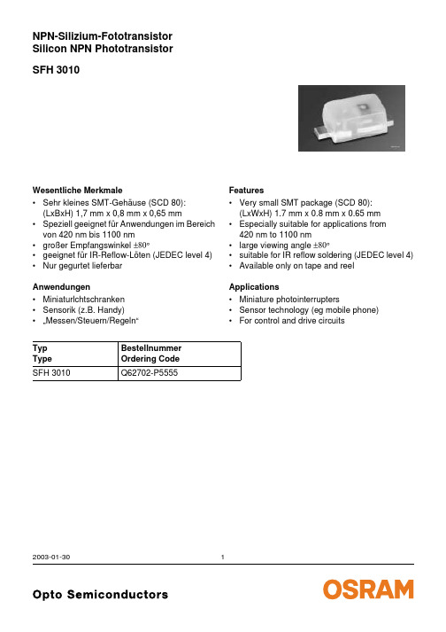
SFH 3010NPN-Silizium-FototransistorSilicon NPN Phototransistor 2003-01-301Wesentliche Merkmale•Sehr kleines SMT-Gehäuse (SCD 80):(LxBxH) 1,7 mm x 0,8 mm x 0,65 mm•Speziell geeignet für Anwendungen im Bereich von 420nm bis 1100nm •großer Empfangswinkel ±80°•geeignet für IR-Reflow-Löten (JEDEC level 4)•Nur gegurtet lieferbar Anwendungen•Miniaturlchtschranken •Sensorik (z.B. Handy)•…Messen/Steuern/Regeln“Typ Type Bestellnummer Ordering Code SFH 3010Q62702-P5555Features•Very small SMT package (SCD 80):(LxWxH) 1.7 mm x 0.8 mm x 0.65 mm •Especially suitable for applications from 420nm to 1100nm•large viewing angle ±80°•suitable for IR reflow soldering (JEDEC level 4)•Available only on tape and reel Applications•Miniature photointerrupters•Sensor technology (eg mobile phone)•For control and drive circuitsGrenzwerte Maximum RatingsBezeichnung Parameter SymbolSymbolWertValueEinheitUnitBetriebs- und Lagertemperatur Operating and storage temperature range Top; T stg– 40…+ 100°CKollektor-Emitterspannung Collector-emitter voltage VCEVCE(t<2min)1530VKollektorstrom Collector current IC15mAKollektorspitzenstrom, τ < 10 µs Collector surge current ICS75mAEmitter-Kollektorspannung Emitter-collector voltage VEC7VVerlustleistung, T A = 25 °C Total power dissipation Ptot130mWWärmewiderstand Sperrschicht - Umgebung bei Montage auf FR4 Platine, Padgröße je 16 mm2 Thermal resistance junction - ambient mounted on PC-board (FR4), padsize 16 mm2 each RthJA585K/W2003-01-3022003-01-303Kennwerte (T A = 25 °C, λ = 950 nm)Characteristics Bezeichnung ParameterSymbol Symbol Wert Value Einheit Unit Wellenlänge der max. Fotoempfindlichkeit Wavelength of max. sensitivityλS max 860nm Spektraler Bereich der Fotoempfindlichkeit S = 10% von S maxSpectral range of sensitivity S = 10% of S maxλ420 (1100)nmBestrahlungsempfindliche Fläche Radiant sensitive area A 0.02mm 2Abmessungen der Chipfläche Dimensions of chip area L ×B L ×W0.38×0.38mm ×mm Halbwinkel Half angleϕ± 80Grad deg.Kapazität CapacitanceV CE = 5 V, f = 1 MHz, E =0C CE1.3pFDunkelstrom Dark currentV CE = 20 V, E =0I CEO2 (≤50)nAFotostrom PhotocurrentE e = 0.5 mW/cm 2,V CE = 5 V I PCE>25µAAnstiegszeit/Abfallzeit Rise and fall timeI C = 1 mA, V CC = 5 V, R L = 1 k Ωt r ,t f7µsKollektrr-Emitter-Sättigungsspannung Collector-emitter saturation voltage I C = 10µAE e = 0.5 mW/cm 2, λ= 950nmV CEsat140mVDirectional CharacteristicsS= f (ϕ)rel2003-01-304Rel. Spectral Sensitivity,PhotocurrentPCE = (A),Dark CurrentCollector-Emitter CapacitanceDark CurrentTotal Power Dissipation2003-01-3052003-01-306Maßzeichnung Package OutlinesMa ße werden wie folgt angegeben: mm (inch) / Dimensions are specified as follows: mm (inch).Published by OSRAM Opto Semiconductors GmbH & Co. OHGWernerwerkstrasse 2, D-93049 Regensburg © All Rights Reserved.Attention please!The information describes the type of component and shall not be considered as assured characteristics.Terms of delivery and rights to change design reserved. Due to technical requirements components may contain dangerous substances. For information on the types in question please contact our Sales Organization.PackingPlease use the recycling operators known to you. We can also help you – get in touch with your nearest sales office.By agreement we will take packing material back, if it is sorted. You must bear the costs of transport. For packing material that is returned to us unsorted or which we are not obliged to accept, we shall have to invoice you for any costs incurred.Components used in life-support devices or systems must be expressly authorized for such purpose! Critical components 1 , may only be used in life-support devices or systems 2 with the express written approval of OSRAM OS.1A critical component is a component usedin a life-support device or system whose failure can reasonably be expected to cause the failure of that life-support device or system, or to affect its safety or effectiveness of that device or system.2Life support devices or systems are intended (a) to be implanted in the human body, or (b) to support and/or maintain and sustain human life. If they fail, it is reasonable to assume that the health of the user may be endangered.Package Epoxy, SmartLED (SCD 80)Colourcolourless, light diffusedPackage marking Collector。
PC塑胶原料特性、用途

PC塑胶原料特性、用途PC塑胶原料特性、用途资料由友人塑胶提供TEL 136 **** ****PC沙特SABIC(原美国GE)100、100R 特性:通用级,良好的综合物理性能,符合FDA 标准,用于食品包装、容器、医疗包装、板材、片材、薄膜以及各种型材等。
PC沙特SABIC(原美国GE)101、101R 特性:通用级,良好的物理机械性能,易脱模,用于一般电子、电气、机械厚壁部件及非对称形状复杂的通用制品等。
PC沙特SABIC(原美国GE)103、103R 特性:通用级,良好的物理机械性能,抗紫外线,优异的耐候性能,用于电子、电气、机械工业部件、家庭日用制品、照明器材以及露天室外器材等。
PC沙特SABIC(原美国GE)104、104R 特性:通用级,良好的物理机械性能,符合FDA 标准,用于食品包装、容器、医疗包装、家庭器皿等。
PC沙特SABIC(原美国GE)121、121R 特性:通用级,超低粘度,高流动,良好的综合物理性能,耐热,用于大型薄壁制品等。
PC沙特SABIC(原美国GE)123、123R 特性:通用级,超低粘度,高流动,良好的综合物理性能,抗紫外线,极好的耐候性能,用于大型薄壁制品等。
PC沙特SABIC(原美国GE)124、124R 特性:超低粘度,高流动,良好的物理机械性能,符合FDA标准,用于食品包装、大型容器、医疗包装、家庭器皿以及薄壁制品等。
PC沙特SABIC(原美国GE)131、131R 特性:挤出或中空吹塑成型,良好的物理机械性能,热稳定,用于管材、板材、中空容器、奶瓶、玩具和各种型材等。
PC沙特SABIC(原美国GE)133、133R 特性:挤出或中空吹塑成型,良好的物理机械性能,耐高温,抗紫外线,优异的耐候性能,用于户外部件、制品、管材、板材、薄膜、中空容器、奶瓶、玩具和各种型材等。
PC沙特SABIC(原美国GE)134、134R 特性:挤出或中空吹塑成型,具有良好的耐冲击强度与耐热性能,符合FDA标准,用于食品包装、容器、板材、薄膜制品、医疗包装、家庭器皿等。
SAA3010中文资料
QUICK REFERENCE DATA
PARAMETER
Supply voltage range Input voltage range (note 1) Input current Output voltage range (note 1) Output current Operating ambient temperature range
Inputs
In the quiescent state the command inputs X0 to X7 are held HIGH by an internal pull-up transistor. When the system mode selection (SSM) input is LOW and the system is quiescent, the system inputs Z0 to Z3 are also held HIGH by an internal pull-up transistor. When SSM is HIGH the pull-up transistor for the Z-inputs is switched off, in order to prevent current flow, and a wired connection in the Z-DR matrix provides the system number.
ground (0 V) scan drivers
oscillator input test point 2 test point 1 sense inputs from key matrix voltage supply
Note
1. (I) = input (IPU) = input with p-channel pull-up transistor (ODN) = output with open drain n-channel transistor (OP3) = output 3-state
异味传感器GS3010空气质量模块
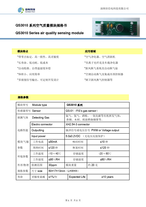
QS3010系列空气质量模块规格书QS3010 Series air quality sensing module模块特点应用领域*带零点标定、高一致性、高灵敏度*空气净化器、空气清新机*长寿命、低功耗、低成本*负离子光纤花及车载净化器*自动校准、自带温湿度补偿*新风换气系统及自动换气扇*体积小、应用简单*空调自动换气及集成吊顶控制器*多级别信号输出,可定制开发设计*厨卫新风换气控制器等规格参数模块型号 Module type QS3010系列传感器型号 Sensor QS-01(FIS’s gas sensor)探测气体 Detecting Gas 氨气、氢气、酒精、一氧化碳等有机挥发气体;香烟、木材、纸张燃烧烟雾等。
Electro connector XH2.54-3 connectorOutputting 脉冲信号或电压信号PWM or Voltage output 电路性能Input power 5.0±0.2VDC (无电压反接保护)工作电流≤50mA 响应时间≤10秒模块气敏参数预热时间≤120秒恢复时间≤120秒工作温度-10 ~ 40℃存储温度-20 ~ 60℃环境参数工作湿度≤95%RH 存储湿度≤60%RH检测范围30ppm 模块重量约20克外形物理规格参数尺寸size 50×17×13mm(L×W×H)寿命灵敏度衰减≤1%/年Expected Life≥10 years引脚定义占空比与污染等级的对应关系:10%~90% 对应于输出值 0~100端口输出信号定义(A loop is 100ms )备注:污染等级数值越高表示空气质量越差注意事项*初次上电使用需预热5分钟以上,灵敏度较佳; *请勿将该模块应用于涉及人身安全的系统中 *请勿将该模块长时间置于高浓度有机气体中 *请勿将模块安装在强空气对流环境下使用Pin 1 VCC (+5V ) Pin 2 GND Pin 3 DATA输出值污染等级 0 0 10 1 20 2 30 3 40 4 50 5 60 6 70 7 80 8 90 9 10010 Pin1。
PMEG3010EP,115;中文规格书,Datasheet资料
103 Zth(j-a) (K/W)
102
10
1
duty cycle =
1 0.75
0.5 0.33
0.25 0.2
0.1 0.05
0.02 0.01
0
006aab298
10−1
10−3
10−2
10−1
1
10
102
103
tp (s)
Ceramic PCB, Al2O3, standard footprint Fig 3. Transient thermal impedance from junction to ambient as a function of pulse duration; typical values
1 A low VF MEGA Schottky barrier rectifier
2. Pinning information
Table 2. Pin 1 2
Pinning Description cathode anode
[1] The marking bar indicates the cathode.
square wave; δ = 0.5; f = 20 kHz
Tamb ≤ 130 °C [1] -
-
1
Tsp ≤ 145 °C
-
-
1
VR
reverse voltage
-
-
30
VF
forward voltage
IR
reverse current
IF = 1 A VR = 30 V
-
320 360
-
total power dissipation
吉尼升降机 GS-30 GS-32 GS-46 GS-47 操作手册说明书

序號範圍GS-1530從GS3010A-110000ANSI/CSA North America South America AsiaGS-1930從GS3010A-110000GS-2032從 GS3211A-110000GS-2632從 GS3211A-110000GS-3232從 GS3211A-110000包含維修資訊GS-2046從 GS4612A-110000GS-2646從 GS4612A-110000GS-3246從 GS4612A-110000GS-4047從 GS4714D-317Sixth Edition Ninth PrintingPart No. T107026CT操作手冊 第六版 • 第九印刷廠GS-30 • GS-32 • GS-46 • GS-47零件號 T107026CT要點操作機器前,應閱讀、瞭解並遵守這些安全規則和操作說明。
只有訓練有素和授權的人員才被允許操作此機器。
應將此手冊當作機器的一部分並永遠與機器一同存放。
如有任何疑問,請與我們聯繫。
請與我們聯繫:網址:電子郵件:*********************目錄簡介 ...................................................................1 符號與危險圖像定義 ..........................................3 一般安全 ............................................................5 人員安全 ..........................................................10 工作區安全 ......................................................11 示意圖 .............................................................20 控制器 .............................................................23 檢驗 .................................................................28 操作說明 ..........................................................54 搬運與提升說明 ...............................................67 維護 .................................................................72 規格 .. (74)© 1997 Terex Corporation 版權所有 第六版:第九印刷廠,2014 年 12 月「Genie 」 是 Terex South Dakota, Inc. 在美國及許多其他國家 的註冊商標。
CW3010 CW3010Y 温湿度变送器 产品手册说明书
温湿度变送器CW3010/CW3010Y产品手册更多详情请登陆:-1-一、概述CW3010/CW3010Y 壁挂式电压输出温湿度变送器选用高质量高精度数字温湿度传感器,具有优良的长期稳定性、低延滞性、强抗化学污染能力和极优的可重复性。
是暖通空调应用中精确测量相对湿度及温度的理想解决方案,广泛应用于楼宇自动化、气候与暖通自动控制、博物馆和宾馆的气候站、暖通空调系统中闭环控制。
外形尺寸(单位:mm)二、产品亮点外型美观、数字化校准、长期稳定性好、标准工业信号输出、全量程温度补偿、温湿度测量范围宽、高低温湿度测量精确。
三、产品选型产品型号产品类型直流电压交流电压输出量规格CW3010壁挂式15~36V DC 12~24V AC 0~10V 常规型CW3010Y 壁挂式15~36V DC12~24V AC0~10VLCD 显示型四、机械安装1、选择一个典型的安装位置:安装变送器的位置必须具备该环境需要测量的典型温度和湿度。
2、务必使变送器周围有足够的空间能使空气能够流通。
3、变送器不要直接安装在发热、制冷物体上,不要直接安装在蒸汽、水雾环境中。
4、积线安装时,务必使变送器远离线路。
注意变送器安装方向,LCD 型以显示字符方向为准,普通型的以文字方向为准。
-2-五、墙面安装1、安装前先将变送器后盖打开,将需要连接的电缆穿过变送器后盖的电缆孔。
2、壳体可以直接安装于墙面或其它位置。
3、用3个M4螺丝(附件有提供)将变送器紧固在墙面上,见下图:六、电气连接以下所有安装操作均必须断开电源-3-连接头各引脚功能如下:安装顺序1、将4芯(或带屏蔽)连接电缆变送器端的四根线分别连接到变送器连接头的1、2、3、4脚(带屏蔽线的屏蔽层连接到电源地);2、另一端对应接入供电电源和电压检测设备或其它相应设备;3、将变送器前后外壳扣紧;4、经检查接线无误后方可接通电源,检查变送器输出是否正常;5、现在变送器可以正常工作了。
七、连接到电源如果每个变送器使用独立的电源,请处理好各变送器的共地问题。
华为海思 EMW3010 Wi-Fi 物联网模组 数据手册说明书

概要●电压输入:3.0V~3.6V●工作环境温度:-40℃to +85℃●处理器:Hi3861(L)处理器,主频高达160MHz●存储器▪352K字节的SRAM▪288K字节的ROM▪2M字节的XIP Flash●Wi-Fi▪IEEE 802.11 b/g/n 1T1R 2.4GHz单频(ch1~ch14)▪支持HT20,72.2Mbps@MCS7▪支持WPA/WPA2 PSK,Open/WEP/ TKIP/CCMP,▪支持WPS 2.0▪支持IEEE Power Save 节能模式▪支持RF 自校准方案▪支持STA 和AP形态,作为AP 时最大支持6 个STA●功耗Ultra Deep Sleep 模式:5μ******内置Hi3861处理器▪DTIM1:**********▪DTIM3:**********内置Hi3861L处理器▪DTIM1:0.9*******▪DTIM3:**********▪DTIM10:250u A@3.3V●接入丰富的外设▪13 x GPIO▪7 x ADC 通道▪ 3 x UART,支持硬件流控制▪ 1 x SPI,1 x I2S▪ 2 x I2C▪ 1 x SDIO▪ 6 x PWM接口和尺寸▪保持与同类封装模组的引脚兼容性▪邮票孔或插针▪适用于照明应用的白色PCB油墨▪板载PCB天线,18 mm x 20 mm●丰富的配套软件▪支持LiteOS操作系统▪支持HarmonyOS操作系统▪提供Hilink云平台接入SDK●典型应用▪智能家电▪智能电工产品▪工业自动化●订货代号订货代号说明EMW3010-PZI6 板载PCB天线,Hi3861处理器EMW3010-PI6A 板载PCB天线,Hi3861L超低功耗处理器EMW3010-EZI6 外接天线IPEX座,Hi3861处理器EMW3010-PZI6-TR 板载PCB天线,Hi3861处理器,卷带包装EMW3010 Wi-Fi物联网模组内置华为海思Hi3861 Wi-Fi Soc,接入华为物联网平台专用2.4G Hz IEEE 802.11 b/g/n,超高集成度,丰富的外设版本:1.4 日期:2021-08-25 编号:DS0160CN系列订货代码例如EMW 3 01 0 -P ZI 6 A -xxx产品系列EMW = 物联网Wi-Fi模组产品类型3 = 焊接类无线模组典型目标应用和功能01 = IOT物联网应用1系列外形尺寸,增强功能0 = 2 x 9 pins 1.5间距邮票孔射频接口P = 18 mm x 20 mm,2.4GHz板载PCB天线Z = 18 mm x 20 mm,2.4GHz 外置天线IPEX接口PSRAM容量(可选)Z=不含PSRAMJ=4M字节的PSRAM温度范围6 = 工业级温度范围,-40°C~85°C可选项A = 使用超低功耗处理器Hi3861L(默认使用Hi3861)可选项TR = 卷带包装(默认使用托盘)如需了解所有相关特性清单(如包装,最小订单量等)和其他方面的信息,请联系就近MXCHIP销售点和代理商。
智能变电站光数字测试仪说明书

目录1. 前言 (1)1.1关于本说明书 (1)1.2安全须知 (1)1.3产品清单 (2)1.4责任声明 (3)2. 概述 (4)2.1功能说明 (4)2.2性能参数 (4)2.2.1基本性能 (4)2.2.2接收性能 (4)2.2.3发送性能 (5)3. 技术参数 (6)3.1环境条件 (6)3.2机械尺寸及重量 (6)3.3电源 (6)3.4电磁兼容性能 (6)4. 操作说明 (7)4.1外观布局 (7)4.1.1接口 (8)4.1.2指示灯 (8)4.1.3按键 (9)4.2开机关机 (10)4.2.1开机 (10)4.2.2HOME菜单 (10)4.2.3锁定 (10)4.2.4关机 (11)4.3主界面 (13)5. 系统设置 (14)5.1基本设置 (14)5.2连接管理 (14)5.3存储器 (15)5.4备份还原 (16)5.5关于 (17)6. 参数配置 (18)6.1基本参数 (18)6.2SMV发送 (19)6.3GOOSE发送 (25)6.4GOOSE接收 (31)7. 手动试验 (36)7.1扩展菜单 (37)7.1.1SMV映射表 (38)7.1.2开入映射表 (40)7.1.3通道品质 (41)7.1.4状态字 (41)7.1.5异常设置 (42)7.1.6显示开入量 (42)7.1.7设置 (43)7.1.8试验结果 (45)8. 状态序列 (49)8.1状态设置 (49)8.1.1故障计算 (52)8.1.2谐波设置 (53)8.2扩展菜单 (54)9. SMV接收 (56)9.1SMV探测 (56)9.2有效值 (57)9.3波形 (62)9.4相量 (63)9.5序量 (64)9.6功率 (65)9.7谐波 (66)9.8双AD (67)9.9核相 (68)9.10极性 (70)9.11MU延时 (71)9.12报文统计 (72)9.13报文监测 (74)9.13.1SCL配置与报文比较 (74)9.13.2报文录波 (74)10. GOOSE接收 (79)10.1GOOSE探测 (79)10.2实时值 (80)10.3变位列表 (82)10.4报文统计 (84)10.5报文监测 (86)10.6间隔监测 (88)11. 录波分析 (89)11.1录制报文 (89)11.2加载文件 (91)12. 对时 (92)12.1对时功能 (92)12.2授时功能 (93)13. 网络压力 (94)13.1网络压力测试 (94)13.2网络流量统计 (95)14. 光功率 (96)15. SCL编辑器 (97)15.1主界面介绍 (97)15.2SMV/GOOSE控制块信息视图区 (97)15.2.1SMV信息视图 (98)15.2.2GOOSE信息视图 (100)15.3导入SCL或SCX文件 (102)15.4导出配置 (103)15.5SMV/GOOSE信息另存为 (103)15.6SMV/GOOSE信息切换 (104)15.7编辑SMV/GOOSE 信息 (104)15.8查找IED (108)16. 使用示例 (109)16.1示例1——IEC60044-7/8报文发送及GOOSE动作信号接收(手动试验) . 10916.2示例2——通过交换机发IEC61850-9-2,收GOOSE信号(状态序列) (110)16.3示例3——接收IEC60044-7/8报文 (111)16.4示例4——接收IEC61850-9-1/2 报文 (112)16.5示例5——接收GOOSE报文 (113)1. 前言1.1 关于本说明书本说明书提供如何以安全的方式使用GDDT6000智能变电站光数字测试仪的准确信息,说明书中详细介绍了安全、规范的操作要领以及各种测量功能的使用流程,请您在使用协议前完整的阅读完本说明书。
Korenix JetNet 3010G系列工业千兆以太网交换机用户手册说明书

JetNet3010G7 10/100TX + 3 Gigabit SFP/Gigabit CopperIndustrial Gigabit SwitchUser’s ManualVersion: 2.2, Jun-2011Korenix JetNet 3010G Series Industrial Gigabit Ethernet SwitchUser’s ManualCopyright NoticeCopyright © 2008 Korenix Technology Co., Ltd.All rights reserved.Reproduction in any form or by any means without permission is prohibited1. Introduction (4)1-1. Features (4)1-2. Packing Check List (4)2. Hardware Description (6)2-1. Dimension (6)2-2. Front Panel (7)2-3. Bottom View (7)2-4. Wiring the Power Input (8)2-5. wiring the Earth ground (9)2-6. LED Indicators (10)2-7. Ethernet interface introduction (11)2-8. Quality of Service (11)2-9. Wiring Cable (12)3. Mounting Installation (13)3-1. DIN Rail Mounting (13)3-2. Wall Mounting (14)4. Hardware Installation (16)4-1 Installation and Testing (16)5. Trouble Shooting (20)6. Technical Specification (20)7. SFP Fiber Transceiver Order Information (22)1. IntroductionIn the traditional industrial communication, the communicate infrastructure is combined with proprietary protocol and hard to connect with different layer. Today, the new trend of industrial communication is integrated all of layers to Ethernet protocol. As the bandwidth demands is growing up by several of applications, like video security, traffic signal monitoring and control; this is a need of Gigabit Ethernet becomes popular in recently.The JetNet3010G is a 10-port Gigabit Industrial switch which embedded 7-port10/100TX and 3 combo ports for Gigabit copper and SFP for Gigabit Ethernet uplink. With the high bandwidth switch fabric, JetNet3010G can deliver full wire speed without packet loss. This manual will introduce JetNet3010G hardware specification, system installation and the applications.1-1. Features7 10/100TX and 3 Gigabit copper/SFP comboIEEE802.3, 802.3u, 802.3z and 802.3ab ComplianceAuto detection Gigabit Transmission MediaFlexible Gigabit Fiber Link DistanceHigh performance 32Gbps Switch fabricSupports Auto MID/MDI-X with Flow controlIEEE802.1p for Quality of Service (QoS)Power redundancy with wide range input1.5KV Hi-pot passed for Port, Power, CaseRigid IP31 grade Aluminum Case-10~60℃ Hazardous Operating Temperature1-2. Packing Check ListJetNet3010G package include the following items:JetNet3010G x1One DIN-Rail clip (already screwed on the back of JetNet3010G) x1 One wall mounting plateUser’s manualQuick Installation GuideJetNet3010G Industrial Switch User’s Manual CD-ROM Quick Installation GuideWall Mounting Plate Screw x 4 (M3 x 6mm)Contact your sales representative if any item is missing or damaged.2. Hardware DescriptionThis session will introduce the enclosure interface, system power installation, dimension and the QoS.2-1. DimensionThe dimension of JetNet3010G is 96 mm (w) x 137 mm (H) x 119 mm (D)2-2. Front PanelThe following diagram shows the front panel of JetNet 3010G, it describes the LEDs, Fast Ethernet and Gigabit Ethernet ports.Figure A. Front Panel of JetNet 3010G2-3. Bottom ViewThe bottom view of the JetNet3010G Industrial Gigabit Switch consists of one terminal block connector with two DC power inputs.Figure B. Bottom view of the JetNet3010G Industrial Gigabit Switch2-4. Wiring the Power InputThe JetNet 3010G supports 2 power inputs with power redundance and polarity auto reverse functions; the typically input power voltage is DC 24V with 12~48V input range. On the bottom side, there is one 4-pin removable terminal block for the redundant power input and the suitable specification of power cable is 12 ~24 AWG.Following the instructions as below to wiring the cable and switching power system. 1. Insert the positive and negative wires into the V+ and V- contacts respectively ofthe terminal block connector2. Tighten the wire-clamp screws to prevent the DC wires from being loosened.3. The Power 1 and Power 2 support power redundancy and polarity reverseprotection functions.4. It accepts positive or negative power system input, but Power 1 and Power 2have to apply the same mode.Note 1: It is a good practice to turn off input and load power, and to unplug power terminal block before making wire connections. Otherwise, your screwdriver blade can inadvertently short your terminal connections to the grounded enclosure.Note 2: The range of the suitable electric wire is from 12 to 24 AWG.Note 3: If the 2 power inputs are connected, JetNet 3010G will be powered from the highest connected voltage. The unit will alarm for loss of power, either PWR1 or PWR2.Note 4: To use the UL Listed LPS Power supply with output Rating 12-48 Vdc, minimum 1 A2-5. wiring the Earth groundTo ensure that the system will not be damaged by noise or any electrical shock, we suggest you make exactly connection with JetNet3010G with Earth Ground.On the bottom side of JetNet3010G, there is one earth ground screw, loosen the earth ground screw by screw drive and tighten the screw after earth ground wire connectedEarth Ground2-6. LED IndicatorsThe front panel of JetNet3010G includes 2 Power LEDs, 6 LEDs for Gigabit SFP and RJ-45 ports. Each 10/100Base-TX ports includes 2 LEDs with Green and Yellow color. These LED indicators provide administrators with real-time system status. Table 1 gives descriptions of the function of each LED indicator.LEDStatus Description Green Power 1 is supplying DC power. Power 1Off No power is being supplied. GreenPower 2 is supplying DC power. Power 2 OffNo power is being supplied. GreenA network device is detected. BlinksThe port is transmitting or receiving packets from the TX device. RJ-45 (Gigabit Port 8~10) OffNo device is attached or not link with RJ-45 port. GreenThe port is transmitting or receiving packets from the TX device. BlinksThe port is transmitting or receiving packets from the TX device SFP (Gigabit Port 8~10) OffNo device is attached or not link with RJ-45 port. GreenA network device is detected. BlinksThe port is transmitting or receiving packets from the TX device 10/100Mbps (Port 1 ~7) off No device is attached or not link with RJ-45 port.Notes 1: It is recommended don’t connect SFP fiber transceiver and RJ-45 combo port at same time; it will cause internal wrong link signature detection and get wrong network connection.Notes 2: Gigabit Port 10 supports 1000Base-T (1000Mbps) or Gigabit Fiber only, but port 8 and 9 support 10/100/1000Mbps or Gigabit Fiber2-7. Ethernet interface introductionThe JetNet 3010G equipped 7 ports 10/100 Fast Ethernet, 3 Gigabit SFP / RJ-45 combo ports. The 10/100Mbps Fast Ethernet ports support auto negotiation andMDI/MDI-X; the Gigabit RJ-45 support 100/1000Mbps for port 8, 9 and port 10 supports 1000Mbps only.The following table shows the link ability of each Ethernet port.Port RJ-45 Link Speed SFPNot Avaliable1~7 10Mbps Full/Half Duplex100Mbps Full/Half Duplex8, 9 RJ-45 /SFP combo1000Mbps Fiber Transceiver10Mbps Full Duplex100Mbps Full/Half Duplex1000Mbps Full/Half Duplex1000Mbps Fiber TransceiverDuplexFull/Half10 1000MbpsNote:The combo port SFP fiber link first function may not work properly, since the most of SFP fiber transceiver vendors have applied energy saving technology into the transceiver and can’t trigger fiber link signature to inform hardware circuit to change the link mode; therefore, it is recommended don’t make connection for SFP fiber link and RJ-45 link at same time.2-8. Quality of ServiceThe JetNet3010G supports IEEE802.1p Tag based Quality of Service (QoS) and based on the priority ID which is embedded in VLAN Tag. The JetNet 3010G per port provides 4 priority queues for packet service and with 8:4:2:1 (Higher: High: Low: Lower) Weight Round Robin (W.R.R.) scheduling. The following table indicates the priority ID and queuing mapping for JetNet3010G.JetNet 3010GPriority Queue Priority IDHigh Queue 6,7Middle Queue 4,5Low Queue 0,3Lowest Queue 1,22-9. Wiring CableRJ-45 port: The RJ-45 cable connection between the JetNet3010G and the attached devices (switches, hubs, workstations, etc.) must be less than 100 meters (328 ft.) long and follows up IEEE 802.3 standard.SFP port: The SFP port permits standard SFP fiber transceiver, which is provided by Korenix with 3.3v DC power supply. The fiber cable of SFP transceiver will depends on SFP fiber transceiver specification. Please notice that the link connection supports either one of RJ-45 or SFP. The SFP Link/Activity LED will be on when Gigabit RJ-45 and SFP Transceiver link with device, because the Fiber link connection always with high priority than RJ-45 port.3. Mounting Installation3-1. DIN Rail MountingThe DIN-Rail clip is already attached to the JetNet3010G when packed. If the DIN-Rail clip is not screwed on the JetNet3010G, follow the instructions and the figure below to attach the DIN-Rail clip to the etNet 3010G.Rear Panel of the JetNet3010G1. Use the screws to attach the DIN-Rail clip to the realpanel of the JetNet3010G.2. To remove the DIN-Rail clip, reverse step 1.Follow the steps below to mount the JetNet3010G to the DIN-Rail track:1. Insert the upper end of the DIN-Rail clip into the back of the DIN-Rail track from its upper side.2. Lightly push the bottom of the DIN-Rail clip into the track.3. Check if the DIN-Rail clip is tightly attached to the track.4. To remove the JetNet3010G from the track, reverse the steps above.Notes: The DIN Rail should compliance with DIN EN50022 standard. Using wrong DIN rail may cause system install unsafe.3-2. Wall MountingFollow the steps below to install the JetNet3010G with the wall mounting plate.1. To remove the DIN-Rail clip from the JetNet3010G, loosen the screws from theDIN-Rail clip.2. Place the wall mounting plate on the rear panel of the JetNet3010G.3. Use the screws to tighten the wall mounting plate onto the JetNet3010G.e the hook holes at the corners of the wall mounting plate to hang theJetNet3010G onto the wall.5. To remove the wall mounting plate, reverse the steps above.4. Hardware InstallationThe following figure illustrates a typical application of JetNet3010G Industrial Gigabit Switch.This figure illustrates an application of JetNet3010G in factory automation. In the figure, JetNet3010G handle entry level control device, like P.Q., O.K.’S. or serial communication device and provides faster uplink ability with a backbone switch, and also provides gigabit interface for monitoring and H.M.I. stations. It aggregates 10/100Mbps bandwidth to Gigabit 1000Mbps and forward to higher level switch.4-1 Installation and Testing1. Take out your JetNet3010G Industrial Gigabit Switch from the packagebox.2. Check if the DIN-Rail clip is attached to the JetNet3010G. If theDIN-Rail clip is not attached to the JetNet3010G, refer to DIN-RailMounting section for DIN-Rail installation. If you want to wall-mountthe JetNet3010G, refer to Wall Mounting section for wall mounting installation.3. To place the JetNet3010G on the DIN-Rail track or wall, refer to theMounting Installation section.4. Pull the terminal block off the JetNet3010G and wire the power lines.Refer to the Wiring the DC Power Inputs section for how to wire the power inputs.5.PWR1 and PWR2 dual power inputs can be connected to powersources simultaneously. When the primary power source fails (the default setting is PWR1), the system will automatically switch to the secondary power source (PWR2), preventing any power interruption.Both of Power 1 and Power 2 support positive electricity and negative electricity power system. Please notice the power system for power 1 and power 2 only accept either positive or negative electricity power system at one time6. Check the LEDs of PWR1 and PWR2 to make sure that JetNet3010Gis operating normally. Use Category 5 straight through Ethernet cables with RJ45 connectors to connect network devices.7.Connect one side of an Ethernet cable with a RJ45 connector to theJetNet3010G’s Ethernet port (RJ-45 port), and the other side of the Ethernet cable to the network device’s Ethernet port (RJ-45 port).8. If you want to connect with Gigabit Fiber, please install appropriateSFP fiber transceiver and fiber cable. To ensure the connection is working, please notice the type of fiber transceiver of JetNet3010G’s and the other end of device.9. Check the port status LED indicator (blinking green) on theJetNet3010G to see if the network connection is successfully established.10. Power on the PC host, activate the Command Line mode, and ping theconnected Ethernet device to see if it will respond.11. To enable the “Command Line mode”, click Run in the Start menu, typeCommand, and click OK to continue.Type ping 192.168.1.1 command to check the connection. Here we use IP address 192.168.1.1 as an example. Before the testing, be sure your PC host and target device are in the same subnet.12. Repeat step 10 to make sure that the connection of each deviceconnected to the JetNet3010G is successfully established.13. Power on the host, activate the Command Line mode, and ping theconnected Ethernet device by typing “ping –t 192.168.1.1” command to see if it will respond.14. The parameter-”t” allow you to continue to ping the network device, asshown in the figure below.Before you continue, make sure that both PWR1 and PWR2 are successfully connected to power sources. When PWR1 fails, the LED for PWR1 will go out. At that moment, if the ping command is still replying, then it proves that redundant power input function works normally.15. E xit the Command Line mode, and connect PWR1 power input. At thisstage, your JetNet3010G has been tested and the installation iscompleted.The industrial network is now established successfully. Computer A is able to connect serial to Ethernet Device via JetNet3010G Industrial Gigabit Switch, providing a reliable network environment. About the test wiring architecture, please refer to the figures as following:5. Trouble ShootingMake sure you are using the correct DC power suppliers (DC12~ 48 V) or power adapters.Select Ethernet cables with specifications suitable for your applications to set up your systems. Ethernet cables are categorized into unshielded twisted-pair (UTP) and shielded twisted-pair (STP) cables. Category 3, 4,5 Ethernet cables are suitable for systems with 10 Mbps transmissionspeed. For systems with 100/1000 Mbps transmission speed, Category 5 Ethernet cables are the only suitable specifications for this environment.Also make sure that the distance between each node cannot be longer than 100 meters (328 feet).If the power LEDs goes off as the power cord plugged in, a power failure might occur. Check the power output connection to see if there is any error at the power source. If you still cannot solve the problem, contact your local dealer for assistance.6. Technical SpecificationStandards IEEE 802.3 10Base-T EthernetIEEE 802.3u 100Base-TX Fast Ethernet IEEE 802.3ab 1000Base-TIEEE 802.3z Gigabit FiberIEEE 802.3x Flow Control and Back pressureProtocols CSMA/CD Technology Store and ForwardTransmission Rate 14,880 pps for Ethernet port 148,800 pps for Fast Ethernet port 1488000 pps for Gigabit EthernetMAC address tablesize8K MAC address table Memory Buffer 1MbitsPort Link Speed Port 1~7: 10/100Base-TXPort 8~9 (Combo ): 10/100/1000Base-TX or Gigabit Fiber (SFP)Port 10 (Combo) : 1000Base-TX or Gigabit Fiber (SFP)Quality of Service Provides Tag Based Class of Service, per port 4 priority queues with 8:4:2:1 W.R.R. rule.Priority ID: High (6,7),Middle (4,5), Low (0,3), Lowest (1,2)LEDs Per Fast Ethernet: Link/Activity (Green) Full duplex/Collision (Orange)Per Gigabit Ethernet: Link/Activity (Green) Per unit: Power 1,Power 2(Green)Network Cables 10Base-T: twisted-pair UTP/STP Cat. 3, 5 cable EIA/TIA-568B 100-ohm (100m)100Base-TX: twisted-pair UTP/STP Cat. 5 cable EIA/TIA-568B 100-ohm (100m)1000Base-T: twisted-pair UTP/STP Cat. 5/5e cable EIA/TIA-568B 100-ohm (100m)Power Supply 12 to 48 VDC, redundant dual DC power inputs with reverse polarity protection.Powerconsumption15 WattsPerformance Switch Fabric: 32Gbps System throughput: 11MppsInstallation DIN-Rail kit or panel wall mountingOperatingTemperature-10℃ to 70℃ (14℉ to 158℉) Operating RelativeHumidity5 to 95% (non-condensing)StorageTemperature-40 to 85°CStorage RelativeHumidity5 to 95%(non-condensing) Dimensions 96 mm (W) x 137 mm (H) x 119mm (D)EMI FCC Class A, CE/EN55022EMS CE/EN61000-4-2 CE/EN61000-4-3 CE/EN-61000-4-4 CE/EN61000-4-5 CE/EN61000-4-6Safety CE/EN60950, IP-31 case protectionStability testing IEC60068-2-32 (Free fall) IEC60068-2-27 (Shock) IEC60068-2-6 (Vibration)7. SFP Fiber Transceiver Order InformationKorenix certificated many types of SFP transceiver. The SFP transceivers we certificated can meet up the industrial critical environment needs. We recommend you to use Korenix certificated SFP transceivers when you constructing your network.Korenix will keep on certificating and updating the certificated SFP transceivers in Korenix web site and purchase list. You can refer to the website to get the latest information about SFP transceivers.Note: Poor SFP transceivers may result in poor network performance or can’t meet up claimed distance or temperature.Model Name Gigabit SFP TransceiverSFPGSX 1000Base-SX multi-mode SFP transceiver,550m, -10~70°CSFPGSX-w 1000Base-SX multi-mode SFP transceiver,550m, wide operating temperature, -40~85°CSFPGSX2 1000Base-SX plus multi-mode SFP transceiver,2Km, -10~70°CSFPGSX2-w 1000Base-SX plus multi-mode SFP transceiver, 2Km,wide operating temperature, -10~70°CSFPGLX10 1000Base-LX single-mode SFP transceiver 10Km, -10~70°CSFPGLX10-w 1000Base-LX single-mode SFP transceiver, 10Km, wide operating temperature, -40~85°CSFPGLHX30 1000Base-LHX single-mode SFP transceiver,30Km, -10~70°CSFPGLHX30-w 1000Base-LHX single-mode SFP transceiver, 30Km, wide operating temperature, -40~85°CSFPGXD50 1000Base-XD single-mode SFP transceiver, 50Km, -10~70°CSFPGXD50-w 1000Base-XD single-mode SFP transceiver, 50Km, wide operating temperature, -40~85°CSFPGZX70 1000Base-ZX single-mode SFP transceiver, 70Km, -10~70°C SFPGZX70-w 1000Base-ZX single-mode SFP transceiver, 70Km, -40℃- 85°C Some of SFP Transceiver model is not listed on the table, please contact Korenix’s distributor for your inquire.Revision HistoryEdition Date ModificationsV2.0 31-July,2008 New Case design (no curve)1. Add port link speed table to remind user about theport 10 only support 1000Mbps in RJ-45.2. Add power installation diagram for UL certificate.Remove company addressV2.1 Apr,2009Modify chapter 2.7 – Ethernet interface:V2.2 Jun,2011Add explanation of Fiber link first functionand recommend don’t plug-in GigabitRJ-45/SFP transceiver at same time.As this result, it is recommended don’t plug-inSFP transceiver and RJ-45 cable at same time, itmay take long time to perform the fiber link firstfeature.。
YSI 3010M 手持导电度 淡度 TDS 温度仪表操作手册说明书
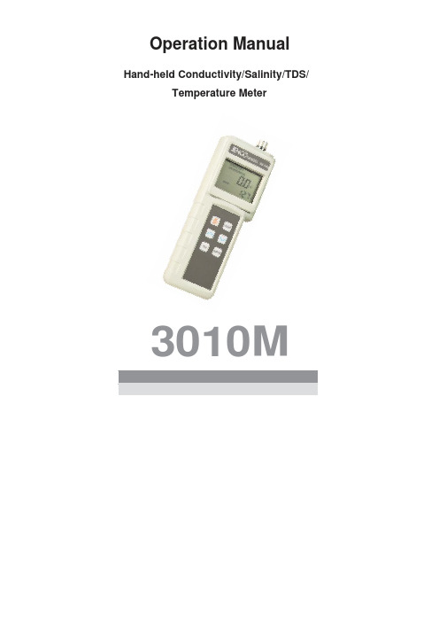
Operation Manual Hand-held Conductivity/Salinity/TDS/Temperature Meter3010MCONTENTS GENERAL INTRODUCTION (2)INITIAL INSPECTION (2)WATER PROOF (2)INSTALLING THE BATTERIES (3)DISPLAY & KEYS FUNCTIONS (4)A. Display (4)B. Keys (5)MODES OF THE METER (6)OPERATIONAL PROCEDURES (8)A. Preparing Standard Solutions (8)B. Calibration (8)C. Conductivity Measurements (10)D. Save, Recall and Delete Data (10)ERROR DISPLAYS AND TROUBLESHOOTING (12)SPECIFICATIONS (13)WARRANTY (14)1Thank you for selecting the 3010M meter. The 3010M is a precision tool that measure conductivity, salinity, TDS and temperature. A built-in microprocessor stores, calculates and compensates for all parameters related to conductivity and temperature determinations. This unit has a waterproof IP65 case. The touch mode keys are highly reliable with tactile and audio feedback. This meter can operate with one 9V battery. Re-calibration is not required when power is restored.The front of the meter has a large LCD that displays temperature and either temperature compensated or non-temperature compensated conductivity, salinity or TDS simultaneously along with user prompts and mode indicators. The unit prompts the user through calibration and measurement procedures.The unit is also equipped with a non-volatile memory allowing the user to store 50 different sets of readings. This unit will assign a site number for each set of reading so the user can review the data easily.The model 3010M is available with three two-wire conductivity cell (K=0.1; 1.0; 10.0). Other features include automatic conductivity ranging, automatic temperature compensation, long battery life, and 50/60 Hz AC noise rejection. This unit is universal and user-friendly for field, industrial and laboratory applications.Carefully unpack the unit and accessories. Inspect for damages made in shipment. If any damage is found, notify your Jenco representative immediately. All packing materials should be saved until satisfactory operation is confirmed.Though the 3010M meter is housed in a watertight case, DO NOTuse it underwater. The watertight case prevents permanent damage to the unit if accidentally dropped into non-corrosive solutions.Follow these steps immediately if the unit is immersed in any solution:1. Rinse unit carefully with distilled water. After rinsing and drying,inspect and clean connectors to remove all contaminants thatmay affect probe connections.22. Wait for the unit and probe to dry completely before resumingoperation.3. If the unit does not function correctly after steps1 and 2, callJENCO for possible repair or replacement (see Warranty).The 3010M meter is packaged with one 9V battery required for operation. To insert the batteries into the meter, follow the procedure outlined below.Figure 1: Battery compartment1. Use a screw driver to remove the two screws and battery coverto expose the battery compartment. (Figure 1.)2. Note the polarity and insert the batteries into the batterycompartment correctly.3. Replace the battery cover and make sure to secure the twoscrews for the water-tight feature.[Note: Press the “ON/OFF” key to turn the unit on. If the unit is running then you can press the “ON/OFF” key to turn the unit off.The unit will automatically turn off after 30 minutes of no key activity.]34A. Display1234567891011121314151617181920Figure 2: Active LCD screen1. BAT-Low battery indicator.8. Delete-To delete stored data.2. Full- This will indicate that all 50 data storage sites are used up.9. Each-To delete a single set of data from the data storage. 3. CELL-Indicates conductivity cellconstant value.10. ℃/%-Displays during calibration:“℃”: Indicates temperature reference unit. “%”: Indicates temperature coefficient unit. 4. TDS- Displays when measuring total dissolved solids. 11. ppt-Parts per thousand for salinity measurement. 5. SALINITY-Displays when measuringsalinity. 12. MAIN DISPLAY- For compensated anduncompensated conductivity,salinity and TDS values. 6. CAL-Calibration mode indicator13. uS/mS-microsiemens or millisiemens for conductivity measurement.7. All- To delete all the data in the data storage. 14. mg/L-Grams/Liter for TDS measurement.515. Temperature and unitdisplay18.CONDUCTIVITY-Displays when measuringconductivity.16. Data storage site number.19. Recall-To recall data from the data storage.17. Save- To save a reading into the data storage. 20. UNCOMPENSATED-Distinguish betweentemperature compensated and non-temperaturecompensated reading.B. KeysON/OFF-Powers on and shuts off the meter.MODE-Selects display mode. In normal operation, press this key to sequentially display compensated conductivity, salinity, total dissolved solids (TDS), uncompensated conductivity, Recall and Delete interface.In calibration mode, press this key to exit the current calibration parameter and enter into the next one. In “Recall” and “Delete” modes, press this key to exit “Recall” and “Delete” modes respectively.UP/DOWN-Increases or decreases the display value as desired.In “Recall” mode, view saved data and data storage site number by pressing these keys.In “Delete” mode, press these keys to select between the “Delete Each” and “Delete All” mode.In “Delete Each” mode, view to be deleted data and data site numbers by pressing these keys.CAL-In “Measurement” mode, press this key to enter into “Calibration” mode.6 ENTER-In “Calibration” mode, press this key to save the current parameter to memory.In “Measurement” mode, press this key to save reading into the next available data storage site.At the Recall interface, press this key to display the last set of saved data.At the Delete interface, press this key to go into “Delete” mode.In the “Delete All” mode, press this key to delete all saved data.In the “Delete Each” mode, press this key to delete a single set of data.1. UNCOMPENSATED mode:The unit will displaynon-temperature compensated conductivity reading.2.COMPENSATED mode: The unit will display temperature compensated conductivity reading.3.TDS mode:The unit will display TDS reading.74.SALINITY mode: The unit will display SALINITY reading.5. Recall interface: Press “ENTER” key to go into recall mode.6. Recall mode:In this mode, user can recall data saved in memory.7. Delete interface: Press “ENTER” key to go into delete mode.8. Delete mode:In this mode, user can erase each data or all data saved in memory.A. Preparing Standard SolutionsSuitable conductivity standards are available commercially or the user can prepare them using research grade reagents.Here are some standard solutions the user can prepare to calibrate the probe of the model 3010M.1. Standard solution of 1413uS at 25℃: Accurately weight out0.746 grams of research grade dried Potassium Chloride(KCL). Dissolve in 1000ml of distilled water.2. Standard solution of 12.90mS at 25℃: Accurately weight out7.4365 grams of research grade dried Potassium Chloride(KCL). Dissolve in 1000ml of distilled water.3. Standard solution of 111.9mS at 25℃: Accurately weight out74.264 grams of research grade dried Potassium Chloride(KCL). Dissolve in 1000ml of distilled water.4. Standard solution of 147uS at 25℃: Accurately measure out100ml of the 1413uS standard solution as in point 1. Dilute itwith 900ml of distilled water.5. Standard solution of 14.94uS at 25℃: Accurately measure out100ml of the 147uS standard solution as in point 4. Dilute itwith 900ml of distilled water.[Note: The user can store the remaining solution in a plastic container for one week but the air space between the cap and the solution must be kept to an absolute minimum. Storing the excess solution below 4℃can increase the storage life. If you have any doubt of the accuracy of the stored solution, a fresh batch should be prepared.]B. CalibrationCalibration setup contains five parameters: TDS, Cell, Temperature Coefficient, Temperature reference and Conductivity Calibration. To access these sections:1. Connect the conductivity probe either the 109A (K=0.1) or the106A (K=1.0) or the 107A (K=10.0) to the unit and turn theunit on. The screen will display the “CELL” icon and the cellconstant of the previous calibration. (Factory default is set atK=1.0).82. Allow temperature reading to stabilize, press “CAL” key toenter the calibration mode. The “CAL” icon appears on theLCD. Press “MODE” key to sequentially view previouscalibration settings.TDSTDS is determined by multiplying conductivity (mS) by a TDS factor. The default factor value is 0.65. To change the TDSfactor, use the “UP” and “DOWN” keys to adjust the valuebetween 0.30 and 1.00. Press “ENTER” key to save the new value and the unit will automatically go into the nextcalibration parameter. If “MODE” key is pressed instead of the “ENTER” key, any changes made will be cancelled and theprevious calibration settings will be retained.CELLUse “UP” and “DOWN” keys to select cell constant between“C0.1” or “C1.0” or “C10.0”on the secondary display. Press“ENTER” key to confirm selection and the unit will thenautomatically go into the next calibration parameter. If“MODE” key is pressed instead of the “ENTER” key, anychanges made will be cancelled and the previous calibration settings will be retained.Temperature CoefficientThe unit uses the temperature coefficient to calculatetemperature compensated conductivity. The default value is1.91%. To change the temperature coefficient, use the “UP”and “DOWN” keys to adjust the value between 0 and 4.00%.Press “ENTER” key to save the new value and the unit willautomatically go into the next calibration parameter. If“MODE” key is pressed instead of the “ENTER” key, anychanges made will be cancelled and the previous calibration settings will be retained.Temperature ReferenceThe unit uses the temperature reference value to calculatetemperature compensated conductivity. The default value is25℃. To change the temperature coefficient , use the “UP”and “DOWN” keys to adjust the value between 15℃ and 25℃. Press “ENTER” key to save the new value and the unit will automatically go into the next calibration parameter. If“MODE” key is pressed instead of the “ENTER” key, anychanges made will be cancelled and the previous calibration9settings will be retained.Conductivity Calibration(a) Immerse the probe in a standard of known conductivity,preferably a standard in the middle range of the solutionsto be measured. Immerse the probe (at least 2” to 3” or5~7cm from the tip) into standard solution without touchingthe sides of the calibration container. Shake the probelightly to remove any air bubbles trapped in theconductivity cell.(b) Allow temperature to stabilize. The message “rAGE”(range) may appear briefly on the display indicatingauto-ranging; this is normal. After temperature stabilization,use the “UP” and “DOWN” keys to adjust the conductivityvalue to that of the conductivity standard at 25℃. Press“ENTER” key to calibrate. The unit beeps to indicate asuccessful calibration. Calibration is now complete and theunit will automatically switch to “Measurement” mode.C. Conductivity Measurements1. Turn the unit on. Place the probe in the solution to bemeasured. Immerse the probe (at least 2” to 3” or 5~7cmfrom the tip) in the sample solution. Shake the probelightly to remove any trapped air bubbles in theconductivity cell.2. Press “MODE” key to enter into the desiredmeasurement mode. The message “rAGE” (range) mayappear briefly on the display indicating auto-ranging; thisis normal. Allow temperature to stabilize.D. Save, Recall and Delete Dataa. Saving readings to memory.1. In compensated conductivity, salinity, total dissolved solids(TDS) and uncompensated conductivity modes, press the“ENTER” key to save data. The “Save” icon with thecorresponding site number will lit up for a brief moment toindicate a successful data save.2. If the “Full” icon is displayed, this means that all 50 data savingsites are used up. No new data can be saved until existingsaved data are deleted.10b. Recalling readings from memory.1. To recall saved data, press “ENTER” key at the Recallinterface to go into “Recall” mode.2. Press the “UP” or “DOWN” keys to select the storage sitenumber.3. Press “MODE” key to exit “Recall” mode.c. Deleting data.1. Press the “ENTER” key at the Delete interface to go into“Delete” mode.2. Select “Delete All” or “Delete Each” mode by pressing the “UP”or “DOWN” key.3. In the “Delete all” mode, press “ENTER” key to clear all storeddata. Deletion is now complete.4. In the “Delete Each” mode, use “UP” and “DOWN” key toselect data to be deleted. Then press “ENTER” key to delete.Deletion is now complete. The next set of saved data willautomatically move up a slot in the storage site.5. Press “MODE” key to exit “Delete” mode.1112[Note: If the unit still does not perform normally after the above measures are taken, call Jenco Service Department.]Main Display Secondary DisplayPossibleCause(s) Corrective Action(s)"OvEr" during measurements/Conductivityis > 400.0mS(K=10.0).Conductivityis > 40.0mS(K=1.0)Conductivityis > 400.0uS (K=0.1)"OvEr " during calibration/Cell Constant Calibration is out of range. Ensure the probe isimmersed at least2”~3” or 5~7cm fromthe tip, below thesurface of thesample/standardsolution.Allow sufficient timefor the electrode and Temp probe to stabilize.Recalibrate with correct value for theconductivity standard. Replace conductivitystandard.Clean cell.ovrTemperature >90.0℃ "OvEr " during measurementsudrTemperature <-10.0℃Decrease/Increase the sample temperature.Display Range Resolution AccuracyConductivity K=0.1 0.000~9.999uS/cm;10.0~99.99uS/cm;100.0~400.0uS/cm0.001uS/cm0.01uS/cm0.1uS/cm±0.5% Full ScaleConductivity K=1.00.00~99.99uS/cm;100.0~999.9uS/cm;1000~9999uS/cm10.00~40.00mS/cm0.01uS/cm0.1uS/cm1uS/cm0.01mS/cm±0.5% Full ScaleConductivity K=10.00.0~999.9uS/cm;1000~9999uS/cm;10.00~99.99mS/cm;100.0~400.0mS/cm0.1uS/cm1uS/cm0.01mS/cm0.1mS/cm±0.5% Full ScaleSalinity 0.0 to 70.0ppt 0.1ppt ±0.2% Full ScaleTemperature -10.0 to 90.0 °C 0.1 °C ±0.2°C or ±0.4% Full Scale, whichever is greater.Reference Temperature 15.0 to 25.0 °C Temperature Coefficient0.0% to 4.0%Cell Constant Two-wire cell: K=0.1; 1.0; 10.0 TDS Constant Range0.30 to 1.00Power9Volt batteryCalibration Back-up EEPROMDatalogging capabilities 50 data setsAutomatic shut offfunction 30 minutes of non-use Audio Feedback All Touch KeysDisplay(Conductivity/Salinity /TDS/mV : Temp)12mm : 8mm high LCD Ambient TemperatureRange0 to 50 °CRelative Humidity At 90% RHCase IP65 waterproof Dimensions (W x D x H)70mm x 198mm x 37mmWeight 260 grams(Batteries included)13Jenco warrants this product to be free from significant deviations in material and workmanship for a period of 1 year from date of purchase. If repair or adjustment is necessary and has not been the result of abuse or misuse, within the year period, please return-freight-prepaid and the correction of the defect will be made free of charge. If you purchased the item from our Jenco distributors and it is under warranty, please contact them to notify us of the situation. Jenco Service Department alone will determine if the product problem is due to deviations or customer misuse.Out-of-warranty products will be repaired on a charge basis. RETURN OF ITEMSAuthorization must be obtained from one of our representatives before returning items for any reason. When applying for authorization, have the model and serial number handy, including data regarding the reason for return. For your protection, items must be carefully packed to prevent damage in shipment and insured against possible damage or loss. Jenco will not be responsible for damage resulting from careless or insufficient packing. A fee will be charged on all authorized returns.NOTE:Jenco reserves the right to make improvements in design, construction and appearance of our products without notice.14Jenco Instruments, Inc.7968 Arjons Drive, Suite CSan Diego, CA 92126 USATEL: 858-578-2828FAX: 858-578-2886E-Mail:********************;****************Website: Jenco Electronics Inc.1F., NO. 11, Lane 370, Sec. 6, Zhongxiao E. Rd. Nangang Dist., Taipei, TaiwanTEL: 886-2-2782-3226FAX: 886-2-2782-3234Shanghai Jenco Instruments, Ltd.18 Wang Dong Zhong RoadSijing Town, SongjiangShanghai, ChinaTEL: 86-021-5761-9599FAX: 86-021-5761-9598E-Mail:****************.cnWebsite: 1516。
- 1、下载文档前请自行甄别文档内容的完整性,平台不提供额外的编辑、内容补充、找答案等附加服务。
- 2、"仅部分预览"的文档,不可在线预览部分如存在完整性等问题,可反馈申请退款(可完整预览的文档不适用该条件!)。
- 3、如文档侵犯您的权益,请联系客服反馈,我们会尽快为您处理(人工客服工作时间:9:00-18:30)。
V MIC IN A IN A OUT A OUTR B INC B IN B OUT GND GND1 R1 GND2 R2 R3
MPO
OUT
MGND
V FEATURES
• Gennum’s LS509 3 stage amplifier
• independent preamp can be used as telecoil preamplifier • four “must use” capacitors mounted on hybrid • choice of 3 resistors to set transducer current • easy assembly and high reliability
STANDARD PACKAGING
•Hybrid typical dimensions
0.276 in x 0.101 in x 0.094in (7.01 mm x 2.57 mm x 2.39 mm)
GS3010 - HYB DATA SHEET
DESCRIPTION
The hybrid consists of an LS509 amplifier, four capacitors,and two selectable bias resistors. The values of the capacitors assure proper operation of the circuit for the most commonly required frequency responses.
If a different frequency response is required, external components can be easily connected to the additional solder pads connected to various amplifier access points.The jumper connection of the on-chip 125 Ω resistor and additional two resistors (58 Ω and 98 Ω) on the hybrid allow adjustment of the transducer bias current of the receiver.
FUNCTIONAL BLOCK DIAGRAM
GS3010 Hybrid with LS509 Amplifier
All resistors in ohms, all capacitors in farads unless otherwise stated.
Revision Date: May 1998GENNUM CORPORATION P.O. Box 489, Stn. A, Burlington, Ontario, Canada L7R 3Y3 tel. +1 (905) 632-2996
Web Site: E-mail: hipinfo@
Document No. 520 - 63 - 05
520 - 63 - 05
2
ABSOLUTE MAXIMUM RATINGS
PARAMETER VALUE/UNITS
Supply Voltage 3 V DC Power Dissipation
25 mW
Operating Temperature Range -10°C to +40°C Storage Temperature Range
-20°C to +70°C
PAD CONNECTION
PARAMETER SYMBOL CONDITIONS MIN TYP
MAX UNITS
Amplifier Current I AMP 75160245 µA Transducer Current I TRANS 1175
225290 µA Transducer Current I TRANS 2S1 = Closed, S3 = Closed 450520600 µA Transducer Current I TRANS 3S1 = Closed, S2 = Closed
650725820 µA Bias Voltage (Pad 15)V P15 1.27 1.3-V Bias Voltage (Pad 5)V P521.5
28.535.5mV System Voltage Gain Gain V IN = -90 dBV 61.564.567.5dB Maximum Power Output
MPO
V IN = -60 dBV
-17
-12
-9
dBV
ELECTRICAL CHARACTERISTICS
Conditions: Frequency = 3 kHz, Temperature = 25°C, Supply Voltage V B = 1.3 V
All conditions and parameters remain as shown in the Test Circuit unless otherwise specified in CONDITIONS Column.V PX - Actual voltage measured on the pin at given condition (X is pin number). Notes:
1. All capacitors on Hybrid ±20%, all screened on resistors ±5%.
1.3V
in farads unless otherwise stated.
Fig. 1 Production Test Circuit
MGND
IN
V MIC
MPO
V B OUT
B IN
C A OUT B OUT R3 GND
520 - 63 - 05
3
EK3033
All resistors in ohms, all capacitors in farads unless otherwise stated.
Fig. 3 Typical Assembly Diagram
Fig. 2 Typical Hearing Instrument Application
520 - 63 - 05
4
GT
VC
LC
FREQUENCY (Hz)
Fig. 5 Frequency Response for Different C LC Capacitors
0-10
-20
-30
-40-130 -120 -110 -100 -90 -80 -70 -60 -50 -40
INPUT LEVEL (dBV)
Fig. 6 I/O Curves at Various R VC Settings
All resistors in ohms, all capacitors in farads unless otherwise stated.
Fig. 4 Characterization Circuit (used to generate typical curves)
O U T P U T L E V E L (d B V )
520 - 63 - 05
5
Dimensions are in inches. Dimensions in parenthesis are in millimetres,converted from inches and include minor round off errors.1.0000 inches = 25.400 mm.
Dimensions ±0.005 (±0.13) unless otherwise stated.Pad numbers for illustration purposes only.Smallest pad 0.023 x 0.013 (0.58 x 0.33).Largest pad 0.036 x 0.027 (0.92 x 0.69).XXXXXX - work order number.
This hybrid is designed for point to point manual soldering.
Fig. 7 Hybrid Layout & Dimensions
DOCUMENT IDENTIFICATION: DATA SHEET
The product is in production. Gennum reserves the right to make changes at any time to improve reliability, function or design, in order to provide the best product possible.
Gennum Corporation assumes no responsibility for the use of any circuits described herein and makes no representations that they are free from patent infringement.
© Copyright August 1992 Gennum Corporation. All rights reserved. Printed in Canada.
REVISION NOTES:
Updated to Data sheet。
