UserDefinedPrimitiveReadMe
Java英语面试题(核心知识篇)

Java英语⾯试题(核⼼知识篇)Java英语⾯试题(核⼼知识篇)Question: What is transient variable?Answer: Transient variable can't be serialize. For example if a variable is declared as transient in a Serializable class and the class is written to an ObjectStream, the value of the variable can't be written to the stream instead when the class is retrieved from the ObjectStream the value of the variable becomes null.Question: Name the containers which uses Border Layout as their default layout?Answer: Containers which uses Border Layout as their default are: window, Frame and Dialog classes.Question: What do you understand by Synchronization?Answer: Synchronization is a process of controlling the access of shared resources by the multiple threads in such a manner that only one thread can access one resource at a time. In non synchronized multithreaded application, it is possible for one thread to modify a shared object while another thread is in the process of using or updating the object's value. Synchronization prevents such type of data corruption.E.g. Synchronizing a function:public synchronized void Method1 () {// Appropriate method-related code.}E.g. Synchronizing a block of code inside a function:public myFunction (){synchronized (this) {// Synchronized code here.}}Question: What is Collection API?Answer: The Collection API is a set of classes and interfaces that support operation on collections of objects. These classes and interfaces are more flexible, more powerful, and more regular than the vectors, arrays, and hashtables if effectively replaces.Example of classes: HashSet, HashMap, ArrayList, LinkedList, TreeSet and TreeMap.Example of interfaces: Collection, Set, List and Map.Question: Is Iterator a Class or Interface? What is its use?Answer: Iterator is an interface which is used to step through the elements of a Collection.Question: What is similarities/difference between an Abstract class and Interface?Answer: Differences are as follows:Interfaces provide a form of multiple inheritance. A class can extend only one other class.Interfaces are limited to public methods and constants with no implementation. Abstract classes can have a partial implementation, protected parts, static methods, etc.A Class may implement several interfaces. But in case of abstract class, a class may extend only one abstract class.Interfaces are slow as it requires extra indirection to to find corresponding method in in the actual class. Abstract classes are fast. Similarities:Neither Abstract classes or Interface can be instantiated.Question: How to define an Abstract class?Answer: A class containing abstract method is called Abstract class. An Abstract class can't be instantiated.Example of Abstract class:abstract class testAbstractClass {protected String myString;public String getMyString() {return myString;}public abstract string anyAbstractFunction();}Question: How to define an Interface?Answer: In Java Interface defines the methods but does not implement them. Interface can include constants. A class that implements the interfaces is bound to implement all the methods defined in Interface.Emaple of Interface:public interface sampleInterface {public void functionOne();public long CONSTANT_ONE = 1000;}Question: Explain the user defined Exceptions?Answer: User defined Exceptions are the separate Exception classes defined by the user for specific purposed. An user defined can created by simply sub-classing it to the Exception class. This allows custom exceptions to be generated (using throw) and caught in the same way as normal exceptions.Example:class myCustomException extends Exception {// The class simply has to exist to be an exception}Question: Explain the new Features of JDBC 2.0 Core API?Answer: The JDBC 2.0 API includes the complete JDBC API, which includes both core and Optional Package API, and provides inductrial-strength database computing capabilities.New Features in JDBC 2.0 Core API:Scrollable result sets- using new methods in the ResultSet interface allows programmatically move the to particular row or to a position relative to its current positionJDBC 2.0 Core API provides the Batch Updates functionality to the java applications.Java applications can now use the ResultSet.updateXXX methods.New data types - interfaces mapping the SQL3 data typesCustom mapping of user-defined types (UTDs)Miscellaneous features, including performance hints, the use of character streams, full precision for java.math.BigDecimal values, additional security, and support for time zones in date, time, and timestamp values.Question: Explain garbage collection?Answer: Garbage collection is one of the most important feature of Java. Garbage collection is also called automatic memory management as JVM automatically removes the unused variables/objects (value is null) from the memory. User program cann't directly free the object from memory, instead it is the job of the garbage collector to automatically free the objects that are no longer referenced by a program. Every class inherits finalize() method from ng.Object, the finalize() method is called by garbage collector when it determines no more references to the object exists. In Java, it is good idea to explicitly assign null into a variable when no more in use. I Java oncalling System.gc() and Runtime.gc(), JVM tries to recycle the unused objects, but there is no guarantee when all the objects will garbage collected.Question: How you can force the garbage collection?Answer: Garbage collection automatic process and can't be forced.Question: What is OOPS?Answer: OOP is the common abbreviation for Object-Oriented Programming.Question: Describe the principles of OOPS.Answer: There are three main principals of oops which are called Polymorphism, Inheritance and Encapsulation.Question: Explain the Encapsulation principle.Answer: Encapsulation is a process of binding or wrapping the data and the codes that operates on the data into a single entity. This keeps the data safe from outside interface and misuse. One way to think about encapsulation is as a protective wrapper that prevents code and data from being arbitrarily accessed by other code defined outside the wrapper.Question: Explain the Inheritance principle.Answer: Inheritance is the process by which one object acquires the properties of another object.Question: Explain the Polymorphism principle.Answer: The meaning of Polymorphism is something like one name many forms. Polymorphism enables one entity to be used as as general category for different types of actions. The specific action is determined by the exact nature of the situation. The concept ofpolymorphism can be explained as "one interface, multiple methods".Question: Explain the different forms of Polymorphism.Answer: From a practical programming viewpoint, polymorphism exists in three distinct forms in Java:Method overloadingMethod overriding through inheritanceMethod overriding through the Java interfaceQuestion: What are Access Specifiers available in Java?Answer: Access specifiers are keywords that determines the type of access to the member of a class. These are: PublicProtectedPrivateDefaultsQuestion: Describe the wrapper classes in Java.Answer: Wrapper class is wrapper around a primitive data type. An instance of a wrapper class contains, or wraps, a primitive value of the corresponding type.Following table lists the primitive types and the corresponding wrapper classes:Primitive Wrapperboolean ng.Booleanbyte ng.Bytechar ng.Characterdouble ng.Doublefloat ng.Floatint ng.Integerlong ng.Longshort ng.Shortvoid ng.VoidQuestion: Read the following program:public class test {public static void main(String [] args) {int x = 3;int y = 1;if (x = y)System.out.println("Not equal");elseSystem.out.println("Equal");}}What is the result?A. The output is equal?br>B. The output in not Equal?br>C. An error at " if (x = y)" causes compilation to fall.D. The program executes but no output is show on console.Answer: CQuestion: what is the class variables ?Answer: When we create a number of objects of the same class, then each object will share a common copy of variables. That means that there is only one copy per class, no matter how many objects are created from it. Class variables or static variables are declared with the static keyword in a class, but mind it that it should be declared outside outside a class. These variables are stored in static memory. Class variables are mostly used for constants, variable that never change its initial value. Static variables are always called by the class name. This variable is created when the program starts i.e. it is created before the instance is created of class by using new operator and gets destroyed when the programs stops. The scope of the class variable is same a instance variable. The class variable can be defined anywhere at class level with the keyword static. It initial value is same as instance variable. When the class variable is defined as int then it's initial value is by default zero, when declared boolean its default value is false and null for object references. Class variables are associated with the class, rather than with any object.Question: What is the difference between the instanceof and getclass, these two are same or not ?Answer: instanceof is a operator, not a function while getClass is a method of ng.Object class. Consider a condition where we use if(o.getClass().getName().equals("ng.Math")){ }This method only checks if the classname we have passed is equal to ng.Math. The class ng.Math is loaded by the bootstrap ClassLoader. This class is an abstract class.This class loader is responsible for loading classes. Every Class object contains a reference to the ClassLoader that defines. getClass() method returns the runtime class of an object. It fetches the java instance of the given fully qualified type name. The code we have written is not necessary, because we should not compare getClass.getName(). The reason behind it is that if the two different class loaders load the same class but for the JVM, it will consider both classes as different classes so, we can't compare their names. It can only gives the implementing class but can't compare a interface, but instanceof operator can.The instanceof operator compares an object to a specified type. We can use it to test if an object is an instance of a class, an instance of a subclass, or an instance of a class that implements a particular interface. We should try to use instanceof operator in place of getClass() method. Remember instanceof opeator and getClass are not same. Try this example, it will help you to better understand the difference between the two.Interface one{}Class Two implements one {}Class Three implements one {}public class Test {public static void main(String args[]) {one test1 = new Two();one test2 = new Three();System.out.println(test1 instanceof one); //trueSystem.out.println(test2 instanceof one); //trueSystem.out.println(Test.getClass().equals(test2.getClass())); //false}}。
IAR基本选项配置
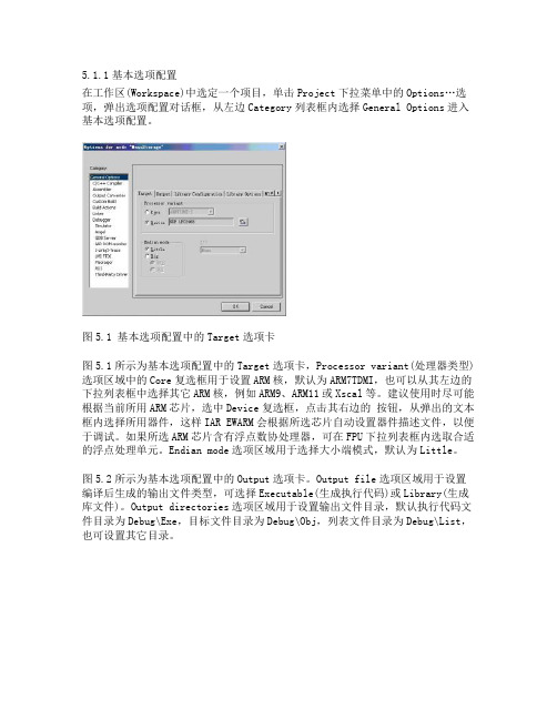
5.1.1基本选项配置在工作区(Workspace)中选定一个项目,单击Project下拉菜单中的Options…选项,弹出选项配置对话框,从左边Category列表框内选择General Options进入基本选项配置。
图5.1 基本选项配置中的Target选项卡图5.1所示为基本选项配置中的Target选项卡,Processor variant(处理器类型)选项区域中的Core复选框用于设置ARM核,默认为ARM7TDMI,也可以从其左边的下拉列表框中选择其它ARM核,例如ARM9、ARM11或Xscal等。
建议使用时尽可能根据当前所用ARM芯片,选中Device复选框,点击其右边的按钮,从弹出的文本框内选择所用器件,这样IAR EWARM会根据所选芯片自动设置器件描述文件,以便于调试。
如果所选ARM芯片含有浮点数协处理器,可在FPU下拉列表框内选取合适的浮点处理单元。
Endian mode选项区域用于选择大小端模式,默认为Little。
图5.2所示为基本选项配置中的Output选项卡。
Output file选项区域用于设置编译后生成的输出文件类型,可选择Executable(生成执行代码)或Library(生成库文件)。
Output directories选项区域用于设置输出文件目录,默认执行代码文件目录为Debug\Exe,目标文件目录为Debug\Obj,列表文件目录为Debug\List,也可设置其它目录。
图5.2基本选项配置中的Output选项卡图5.3基本选项配置中的Library Configuration选项卡图5.3所示为基本选项配置中的Library Configuration选项卡。
IAR C/C++编译器提供了DLIB库,支持ISO/ANSI C和C++以及IEEE754标准的浮点数。
通过Library下拉列表框选择希望采用的运行库。
选择None表示应用程序不链接运行库;选择Normal表示链接普通运行库,其中没有locale接口和C locale,不支持文件描述符,printf and scanf不支持多字节操作,strtod不支持十六进制浮点数操作。
promela 语法
promela 语法Promela(Process Meta Language)是一种用于规范和验证并发系统的建模语言,特别与SPIN模型检查器相关。
以下是Promela的基本语法概述:进程:Promela模型由一个或多个并发进程组成。
使用proctype关键字定义进程。
例如:proctype MyProcess() {// 进程体}变量:可以使用chan或mtype关键字声明变量。
例如:byte variable1;int variable2;chan channel;初始化:init进程是启动系统的初始进程。
例如:init {// 初始化代码}原子块:使用atomic块可以指定临界区。
例如:atomic {// 临界区代码}通道:进程之间的通信使用通道完成。
可以使用chan关键字声明通道。
例如:chan myChannel = [10] of {int};消息类型:可以使用mtype关键字定义消息类型。
例如:mtype = {MSG_TYPE1, MSG_TYPE2, MSG_TYPE3}; 发送和接收消息:使用!操作符发送消息,?接收消息。
例如:chan myChannel = [1] of {int}; // 发送myChannel!42;// 接收myChannel?x;条件语句:使用标准的if、else和do语句。
例如:if (condition) {// 条件为真时执行的代码} else {// 条件为假时执行的代码}循环:使用do循环进行迭代。
例如:do:: (condition) -> // 执行的代码:: else -> breakod断言:使用assert指定必须始终保持的属性。
例如:assert(condition);这些只是Promela语法的基础。
在实践中,Promela通常与SPIN 模型检查器一起使用,以验证并发系统的属性。
模型检查器会探索所有可能的进程交错,并检查指定的属性在所有情况下是否成立。
JMS ActiveMQ交流学习 演示文稿

简单的说,JMS制定了一个发消息的规范。是一个与具体平台无关的
API,绝大多数MOM提供商都对JMS提供支持。
ActiveMQ是Apache出品的开源项目,它是JMS规范的一个实现,
JMS的作用
在不同应用之间进行通信或者从一个系统传输数据到 另外一个系统。两个应用程序之间,或分布式系统中发送消息,进行异 步通信。
Jms消息订阅者流程图
JMS消息的事务
1.创建事务createSession(paramA,paramB);
paramA是设置事务的,paramB设置acknowledgment mode(应答模式) paramA设置为false时:paramB的值可为Session.AUTO_ACKNOWLEDGE,Session.CLIENT_ACKNOWLEDGE, DUPS_OK_ACKNOWLEDGE其中一个。
MOM在系统中的位置
JMS模型
Java消息服务应用程序结构支持两种模型: 1.点对点模型(基于队列)
每个消息只能有一个消费者。消息的生产者和消费者之间没有时间上的 相关性.可以由多个发送者,但只能被一个消费者消费。 • 一个消息只能被一个接受者接受一次 • 生产者把消息发送到队列中(Queue),这个队列可以理解为电视机频道(channel) • 在这个消息中间件上有多个这样的channel • 接受者无需订阅,当接受者未接受到消息时就会处于阻塞状态
JMS定义的消息类型有TextMessage、MapMessage、BytesMessage、 StreamMessage和ObjectMessage。
目的地:Destination,消息的目的地,是用来指定生产的消息的目标和 它消费的消息的来源的对象。 消息队列:Queue 点对点的消息队列 消息主题:Tipic 发布订阅的消息队列
createprocessasuser 命令行参数

CreateProcessAsUser是Windows API 中的一个函数,用于在另一个用户的上下文中创建一个新的进程。
这个函数通常用于提升权限或以特定用户的身份运行程序。
在使用CreateProcessAsUser函数时,你需要提供以下参数:hToken: 一个令牌句柄,代表要以其身份创建进程的用户的访问令牌。
lpApplicationName: 要执行的模块的名称。
这通常是一个可执行文件的路径,如C:\Windows\System32\notepad.exe。
lpCommandLine: 指向一个以空字符结尾的字符串,指定要执行的应用程序的命令行。
如果此参数为NULL,则lpApplicationName字符串用作命令行。
lpProcessAttributes: 一个安全描述符,用于确定新进程是否可以被子进程继承。
lpThreadAttributes: 一个安全描述符,用于确定新线程是否可以被子线程继承。
bInheritHandles: 如果为TRUE,则新进程继承调用进程的句柄。
dwCreationFlags: 控制新进程的创建标志。
lpEnvironment: 指向新进程的环境块的指针。
lpCurrentDirectory: 指向一个以空字符结尾的字符串,指定进程运行的目录。
如果此参数为NULL,则模块名称必须是lpCommandLine字符串中的第一个以空格分隔的标记。
lpStartupInfo: 指向STARTUPINFO 或STARTUPINFOEX 结构的指针,该结构包含有关新进程的主窗口的信息。
lpProcessInformation: 指向PROCESS_INFORMATION 结构的指针,该结构接收新进程的标识符和主线程的标识符。
请注意,为了使用CreateProcessAsUser,你需要有足够的权限来执行该操作,并且你可能需要处理各种错误情况。
在使用此函数之前,建议详细阅读相关的文档和示例代码。
oracle 常见英文

record relation 关系 view 视图 command insert query search sort restore恢复
object configuration配置 SQL:Structed Query Language :结构化查询语言 cursor:光标
OS:(Operateion System):操作系统 advanced高级的 administator管理员
guest permission:权限 priority优先级 valid 有效的 refresh setup,install安装
uninstall卸载 program程序 wizard向导 license 许可证 back,previous 上一步
css:Cascading Style sheet 样式表 CM:communication Management 通信管理 control 控制器 cross 通过 command命令 condition 条件 complete 完成,全部的 create 创建 category 类别 composite 合成的 custom 定制 compare 比较
argument参数 prompt 提示符 copyright 版权 project current-file path
enviroment variable环境变量 characterset字符集 release 发布 settings 设置
structrue 结构 new version datachange data flow data type database数据库
B/s :Browser /server 浏览器/服务器 network 网络 www :world wild web万维网
VC常用数据类型总结
VC常用数据类型总结VC(Visual C++)常用数据类型指的是在C++编程中经常使用的数据类型。
根据数据类型的特性和用途不同,VC常用数据类型可以分为以下几类:1. 基本数据类型(Primitive Data Types):- 整型(Integer Type):用于表示整数,包括有符号整数(signed)和无符号整数(unsigned),例如int、short、long、char等。
- 浮点型(Floating-Point Type):用于表示带小数点的数值,包括单精度浮点型(float)和双精度浮点型(double)。
- 字符型(Character Type):用于表示单个字符,例如char类型。
- 布尔型(Boolean Type):用于表示真(true)或假(false),例如bool类型。
2. 高级数据类型(Advanced Data Types):- 数组(Array):用于存储多个相同类型的元素,例如int数组、char数组等。
- 结构体(Structure):用于封装多个不同类型的变量,例如定义一个包含姓名、年龄等信息的Student结构体。
- 枚举(Enumeration):用于定义一组相关的常量,例如定义星期几的枚举类型。
3. 指针(Pointer):- 指针(Pointer):保存变量的内存地址,可以通过指针间接访问变量的值,例如int*指针。
- 空指针(Null Pointer):指向无效内存地址的指针,通常表示指针未初始化或指向不存在的对象。
- 空指针常量(Null Pointer Constant):表示空指针的特殊值,通常用NULL或nullptr表示。
4. 自定义数据类型(User-Defined Data Types):- 类(Class):用于创建自定义的数据类型,包含数据成员和成员函数。
- 模板(Template):用于创建通用的数据类型,支持不特定的数据类型参数,例如STL容器类(vector、list等)的模板类型。
Verilog HDL 用户定义原语(UDP)
只允许一个输出端口,输入最多 允许10个 输入/输出端口位宽只能是1位; UDP不支持inout端口; reg可选,只有时序逻辑才需要;
initial可选,只有时序逻辑才需 要 状态表的项可以包含0、1或x, 但不能是z,传递给UDP的z值被 当作x值。
UDP与模块同级,不能在模块 内部定义,只能在模块内部被 调用。UDP调用与门级内置原 语完全相同。
UDP一般是使用内存查找表来实现的。如果输入端口数过多,则不宜使用UDP。
UDP并不总是设计功能模块的最佳方式。有时将功能模块设计成module更容易。 例如,用UDP设计8选1多路选择器并不可取,因为输入项数太多。而用数据流 描 述方式或行为描述方式要简单得多。
应该尽可能完整地描述UDP的状态表。输入组合没有对应项的输出为x。
2. clr=0, clk=1, q=d; 3. clr=0, clk=0, q不变.
//以UDP形式编写电平敏感锁存器 primitive latch(q, d, clk, clr);
//端口声明 output reg q; //时序输出用reg类型 input d, clk, clr;
//时序UDP初始化,只允许有一条initial语句
5.2 用户定义原语—时序电路
【例】 带异步清零的D触发器的UDP描述。
primitive D_Async_FF(Q, Clk, Clr, Data);
output Q;
reg Q;
input Clr, Data, Clk ;
table //Clk Clr
Data : Q (State) :Q(next)
//UDP名和端口列表 primitive UDP_name (输出端口, 输入端口);
ch08_用户定义原语(UDP)a

第8 章用户定义原语(UDP)内容UDP基础组合逻辑的UDP时序逻辑的UDPUDP表中的缩写符号 UDP设计指南UDP基础UDP(User-Defined Primitives )Verilog 不仅提供了一套标准的内置原语,还允许用户定义自己的原语 UDP的类型有两种表示组合逻辑的UDP输出由输入信号的组合逻辑确定表示时序逻辑的UDP输出由当前输入信号和内部状态确定UDP 定义的组成主要定义规则只有一个1 bit 输出端,端口列表中的第一个如果定义的是表示时序逻辑的原语,输出端口必须声明为reg 类型使用input 声明输入端口,不支持inout 端口时序逻辑UDP 的输出可以用initial 初始化状态表中可包含的值为0、1和x ,不能有zUDP 与模块同级组合逻辑的UDP例、自定义与门——udp_and状态表中每一行的语法primitive udp_and(out, a, b);output out; //组合逻辑的输出端不能声明成 reg 类型input a, b; // 输入端口声明//定义状态表table// a b : out;0 0 : 0;0 1 : 0;1 0 : 0;1 1 : 1;endtableendprimitive所有输入组合必须在状态表中列出,否则,在状态表中找不到对应输入的项,产生输出为x例、所有可能的输入组合无关项的缩写表示无关项不影响输出值的输入项无关项可用符号“?”表示?——自动展开为0、1或x例primitive udp_or(out, a, b);output out;input a, b;table// a b : out;0 0 : 0;0 1 : 1;1 0 : 1;1 1 : 1;x 1 : 1;1 x : 1;endtableendprimitiveUDP 原语的实例引用primitive udp_or(out, a, b);output out;input a, b;table// a b : out0 0 : 0;1 ? : 1;? 1 : 1;0 x : x;x 0 : x;endtableendprimitive组合逻辑UDP 设计四选一多路器primitive mux4_to_1 ( output out,input i0, i1, i2, i3, s1, s0); table// i0 i1 i2 i3, s1 s0 : out1 ? ? ? 0 0 : 1 ;0 ? ? ? 0 0 : 0 ;? 1 ? ? 0 1 : 1 ;? 0 ? ? 0 1 : 0 ;? ? 1 ? 1 0 : 1 ;? ? 0 ? 1 0 : 0 ;? ? ? 1 1 1 : 1 ;? ? ? 0 1 1 : 0 ;? ? ? ? x ? : x ;? ? ? ? ? x : x ;endtableendprimitive四选一多路器UDP仿真测试时序逻辑的UDP特点输出必须为reg 类型 输出可用initial 初始化状态表格式两种时序逻辑UDP电平敏感对输入信号的电平敏感边沿敏感对输入信号的边沿敏感电平敏感的时序逻辑UDP带清零端的电平敏感锁存器根据输入电平改变状态功能若clear 为1,输出q 恒为0若clear 为0如果clock 为1,q = d如果clock 为0,保持q边沿敏感时序逻辑UDP根据边沿跳变与/或输入电平改变其状态例、带清零端的下降沿触发的D触发器功能若clear = 1,则q 的输出恒为0若clear = 0当clock 从1 跳变到0 时,则q = d,否则,q 保持不变当clock 保持稳定时,而d 改变值,q 不变带清零端的下降沿触发的D 触发器边沿跳变(10) ——从1 到0 负边沿跳变(1x) ——从1 到x 的跳变(0?) ——从0 到0、1或x 的跳变(??) ——从0、1和x 到0 、1和x 任意跳变状态表——每行只能输入一个跳变沿时序逻辑UDP举例使用UDP设计一个4位行波计数器 用UDP描述一个T 触发器引用T触发器// 行波计数器module counter(Q , clock, clear);output[3:0] Q;input clock, clear;T_FF tff0(Q[0], clock, clear);T_FF tff1(Q[1], Q[0], clear);T_FF tff2(Q[2], Q[1], clear);T_FF tff3(Q[3], Q[2], clear);endmoduleUDP 表中的缩写符号信号值的任意变化(??)*可能是下降沿(10), (1x) or (x0)n 可能是上升沿(01), (0x) or (x1)p 信号的下降沿(10)f 信号的上升沿(01)r 只能用于时序逻辑UDP 保持原值不变-不能用于输出部分0, 1b 不能用于输出部分0, 1, x ?解释含义缩写符UDP设计指南限制主要用于功能建模只能有唯一的输出端口输入端口的数目由仿真器决定要点应当完整地描述UDP的状态表注意电平敏感输入项的优先级高于边沿敏感的优先级。
8P12S电机的参数化建模与齿槽转矩分析
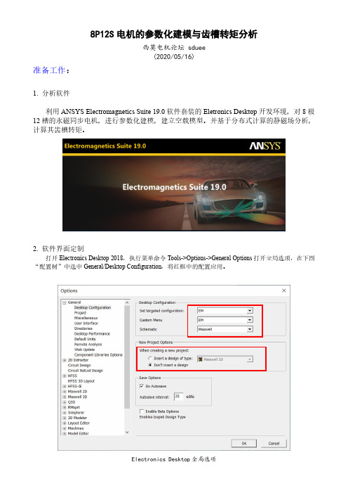
8P12S电机的参数化建模与齿槽转矩分析西莫电机论坛 sduee(2020/05/16)准备工作:1. 分析软件利用ANSYS Electromagnetics Suite 19.0软件套装的Eletronics Desktop开发环境,对8极12槽的永磁同步电机,进行参数化建模,建立空载模型。
并基于分布式计算的静磁场分析,计算其齿槽转矩。
2. 软件界面定制打开Electronics Desktop 2018,执行菜单命令Tools->Options->General Options打开全局选项,在下图“配置树”中选中General/Desktop Configuration,将红框中的配置应用。
Electronics Desktop全局选项退出Electronics Desktop 2018后,再次打开,在菜单栏执行View->Component Libraries ,去掉这一项的对号,关闭其显示。
同时在View 菜单中选择Message Manager 和Progress ,显示信息栏、进度栏,得到图3所示的界面布局。
一、 建立原始模型1. 执行File->New ,建立新工程文件(图1)图1 建立工程文件并重命名2. 右击Project1->Rename ,将工程名改为8P12S_Parametric3. 右击这个工程名,Insert-> Insert Maxwell 2D Design ,在工程文件内,建立Maxwell 2D 有限元项目4. 右击Maxwell2DDesign1->Rename ,将项目名改为Parametric_Design_1(图2)菜单栏 模型树信息栏进度栏图2 建立Maxwell 2D有限元分析项目并重命名5.右击Parametric_Design_1->Solution Type, 求解类型选择Magnetic: Transient,坐标系选择笛卡尔坐标系”Cartesian, XY”图3 Solution Type对话框6.生成定子铁心模型执行Draw->User Defined Primitive->RMxprt->SlotCore 。
redefinition of main怎么解决

redefinition of main怎么解决当你在编程中遇到“redefinition of main”的错误,这通常意味着你在同一个源文件中多次定义了main函数。
在C或C++等语言中,main函数是程序的入口点,只能有一个。
为了解决这个问题,你可以按照以下步骤操作:1.检查源文件:确保你的源文件中只有一个main函数定义。
如果你不小心在头文件中定义了main函数(这是非常不建议的),那么当你包含这个头文件到多个源文件中时,就会出现多次定义的问题。
2.检查包含的头文件:如果你在头文件中定义了函数或变量,确保它们被声明为extern,这样它们就只在某个源文件中定义,而在其他源文件中只是声明。
避免在头文件中定义main函数。
3.使用源文件编译:如果你有多个源文件,并且每个源文件都有一个main函数,那么你需要确保只有一个源文件被编译为可执行文件。
你可以使用编译器的选项来实现这一点,例如使用GCC的-c选项来只编译源文件,然后使用链接器来链接这些编译后的目标文件。
4.检查项目设置:如果你使用IDE(如Visual Studio、Code::Blocks等),检查项目设置,确保没有错误地包含了多个包含main函数的源文件。
5.重新组织代码:如果你的程序结构不合理,导致你需要在多个地方定义main函数,那么你可能需要重新组织你的代码,使其更符合逻辑和编程规范。
6.使用静态库或动态库:如果某些功能需要在多个源文件中使用,但又不希望main函数被多次定义,你可以考虑将这些功能放入静态库或动态库中,并在需要的地方链接这些库。
总之,当你遇到“redefinition of main”的错误时,最重要的是确保你的程序中只有一个main函数,并且它被正确地定义和链接。
cmakefile main的多重定义

cmakefile main的多重定义CMake是一个跨平台的开源构建工具,可以自动生成Makefile、Visual Studio等工程文件,方便项目的构建和管理。
然而,在使用CMake时,有时会遇到main函数多重定义的错误,这是因为在编译链接时,出现了多个相同的main函数。
本文将介绍该错误的原因及解决方法。
一、错误原因在编写C++程序时,每个文件都需要有一个唯一的main函数,这是程序的入口点。
在使用CMake构建项目时,如果多个源文件中都定义了main函数,则在编译链接时就会出现多重定义的错误。
二、解决方法1.将main函数放在一个源文件中将main函数放在一个源文件中,其他源文件只负责定义函数和变量。
这样,在编译链接时就不会出现多重定义的问题。
2.使用条件编译使用条件编译可以避免多重定义的问题。
在每个源文件中,使用#ifndef和#endif包含main函数,这样只有第一个包含main函数的文件会被编译链接。
例如,在每个源文件中添加以下代码:#ifndef MAIN_H_INCLUDED#define MAIN_H_INCLUDEDint main(){//...return 0;}#endif3.使用静态库将main函数放在一个源文件中,编译成静态库,并链接到其他源文件中。
这样,在编译链接时就不会出现多重定义的问题。
4.使用命名空间使用命名空间可以避免函数和变量名称的冲突。
将main函数放在命名空间中,其他源文件也使用相同的命名空间。
例如,在每个源文件中添加以下代码:namespace myNamespace{int main(){//...return 0;}}5.使用extern声明在每个源文件中,使用extern声明main函数,这样只有第一个定义main函数的文件会被编译链接。
例如,在每个源文件中添加以下代码:extern int main();三、总结main函数多重定义是一个常见的错误,但可以通过以上几种方法进行解决。
redmine 枚举
redmine 枚举(最新版)目录1.红矿概述2.红矿的安装与配置3.红矿的枚举功能4.红矿枚举的应用实例5.红矿枚举的优缺点正文红矿是一款开源的基于 Web 的项目管理工具,它可以帮助团队进行项目计划、任务分配、进度跟踪等工作。
红矿的枚举功能是其一个重要的特性,可以让用户自定义各种属性和状态,以便更好地管理项目。
下面我们就来详细介绍一下红矿的枚举功能。
红矿的安装与配置非常简单,只需要下载最新版本的红矿软件,然后按照官方的指导文档进行安装和配置即可。
安装完成后,用户可以登录红矿,开始创建项目和任务。
在红矿中,枚举是一种数据类型,它可以让用户自定义各种属性和状态。
例如,在创建一个项目时,用户可以定义项目的状态为“待开始”、“进行中”、“已完成”等。
同样,在创建一个任务时,用户也可以定义任务的状态为“待分配”、“进行中”、“已完成”等。
红矿的枚举功能不仅可以用于定义项目的状态,还可以用于定义其他各种属性和状态。
例如,用户可以定义一个“任务类型”的枚举,包括“开发任务”、“测试任务”、“部署任务”等。
这样,用户就可以根据不同的任务类型来分配任务,从而更好地管理项目。
红矿枚举的应用实例非常广泛,可以用于定义各种属性和状态,以便更好地管理项目。
例如,在创建一个项目时,用户可以定义项目的状态为“待开始”、“进行中”、“已完成”等。
同样,在创建一个任务时,用户也可以定义任务的状态为“待分配”、“进行中”、“已完成”等。
红矿枚举的优缺点也非常明显。
优点是可以让用户自定义各种属性和状态,更好地管理项目。
缺点是枚举的定义和使用需要用户具有一定的技术水平,否则可能会出现错误。
综上所述,红矿的枚举功能是一个非常实用的特性,可以让用户自定义各种属性和状态,更好地管理项目。
manual
Overview of this manualAbout this manualThis manual contains information about ford Handzhoukawasaki robot software .UsageThis manual describe base application software which handleplc basic IO communication(job,fault,interlock,HMI ..). This manual also describe all the routines usedfor sealing,welding,handling,stud welding,fastwelding, brushing.Who should read this manualThis manual is intended for :•Personnel in charge of robot programming•Personnel in charge of installation•Personnel in charge of commissioning•Personnel in charge of maintenanceUser qualificationAn operator only requires minimal information andinstruction for operating the installation in order to beable to work with kawasaki robot.A programmer should be familiar with kawasaki programmingand be sufficiently trained for the kawasaki robotprocedure.In particular he should be familiar with the followingitems :•Kawasaki robot programming language AS•Kawasaki bloc teaching languageWhat is base applicationDescriptionBase application is a software module that is present onevery robots which handles plc communication, HMI and whichgive service to other application.Base application handles :•robot program safety(robot position at start-up, robot stop on hold request from plc ..)•Jobs : in conjunction with plc base application start the requested job number•Work authorisation:in conjunction with plc work authorisation are handled•Interlocks:PLC manage interlocks and the case effective give a robot a privilege access .•Error and alarm reporting : Base application reports error and alarm to PLC for a centralised viewing.•A dedicated Human Machine Interface is displayed on the robot teach pendant to help users in case oftroubleshooting. This HMI allows in some special caseuser to make some configuration (e.g: gripper)Terms and conceptsUsageThis chapter contains information relative to path organisation and controls user can achieve.Production tasks are achieve through path chosen by a remote controller.The remote controller(eg PLC)send information (IO) through an industrial network (Profinet) the robot get this informations and select the path. Communication length is128bits.Each bit has a signification and these bits are the same on every robot on the line (standard definition of IO exchange for PLC). We define a cycle as a program number (eg a car type) , during the cycle program execution can be synchronised with PLC,such a way of programming avoid collision and allow PLC to track robot job on some specific positions.Specific positionsHOMEUsually a cycle starts from a specific position(HOMEposition) and finish at the same position.HOME position is a global and unique position , the robotinternal software checks if each axis position are in arange of 2 degrees and set the case of the output robot inHOME. A new cycle is only taken in account if the robot isat HOME position. For robot safety at program start-up thisposition is checked and if the robot is any elsewhere theuser is invited to drive the robot by hand to home .PLCsynchonisationKawasaki user program.PROGRAM pg10()#230HOME ; needed as standard commandCALL hometopeo10; must provide a home to pounce programCALL peojob(10); must call peojob with pg numberIF zendcyclereq GOTO endcycle ; needed by application; synchronisation primitiveCALL waitforsegment(16,"Spot Car Chb10GEO","¹Ì¶¨º¸½Ó")CALL spotchb10geo ; work programCALL endsegment(16) ; synchronisation primitiveHOME ; needed as standard commandendcycle: ; needed end of cycle management.ENDPEOX (E.G PounceX)To avoid cycle time issue ( we specified that HOME positionis a global position )we need to have another specificposition near the robot work. This position is to be taughtout of collision and is specific to the job number (programsent by PLC indicating task to be done).User must provide two program for safely drive to and fromHOME position•Hometopeo X•Peo X toHomeWhere X is the job number. User cannot change these namesbecause they are automatically called by base applicationwhen PLC request to drive back to HOME (abort the task).Nb : for code number 10 (PG10) these path are called•Hometopeo10•Peo10ToHomeService positionA service position is needed for some process,it allowuser to enter in the cell to do some maintenance operations(cleaning , check ..) .Service position can be freely programmed user must onlycall a routine named“inservice“.When this routine iscalled plc allow user to enter in the cell when allmaintenance operations are finish the operator issue acycle start and robot main cycle can restart.Tip change positionA service position is needed for some process,it allowuser to enter in the cell to do some operations.Forexample in welding process , tips need to be changed sowhen the robot is in service position user can enter in thecell and change them.Service position can be freely programmed user must onlycall a routine named“intipchg“.When this routine iscalled plc allow user to enter in the cell when tip arechanged the operator issue a cycle start and robot maincycle can restart.Robot main programDescriptionRobot main task is program“zmain”,this program ismonitored by background task and selected automaticallywhen the robot is in automatic mode (this to avoid that anunhallowed program run in automatic mode). The main task ofthis program is to check initialize some parameters, checkif robot at start-up is at HOME position and then selectthe task to be done according to PLC request.Synchronisation primitivesDescriptionIn order to synchronise robot movement and plc task wedefine some functions to allow user to interact with PLC.Through pre-defined IO robot communicate with PLC.There is 3 kind of synchronisation objects :•Area or segment•Interlocks•Service positionArea / segment synchronisation objectWhen performing job task the robot need to wait for someevent to arise(like car in position,table rotationfinished , …) to do this user need at some position to calla predefined routine and ask plc to grant him the access.This action is performed by calling :•WaitforSegmentUser should call this function after a fine point (accuracyset to 0) and provide some parameters :• area number : (integer from 1 to 16) given by PLC• area description in english (string)• area description in chinese (string); synchronisation primitiveCALL waitforsegment(16,"Spot Car Chb10GEO","¹Ì¶¨º¸½Ó")When requested operation is finished and in order to staysynchronised with PLC user need to inform PLC. To do souser must call :•EndSegmentAnd provide one argument :•area number; synchronisation primitiveCALL endsegment(16)Example :Here in this sample the robot task is pick a part ,weldthen drop it on the car. To perform such a task we willneed at least 3 area :•Area 1 - PLC grant access to pick the part•Area 2 – PLC grant access to weld the part•Area 2 – PLC grant access to drop the partThen the robot program should be like.PROGRAM pg 10()HOME ; needed as standard commandCALL hometopeo 10; must provide a home to pounce programCALL peojob(10); must call peojob with pg numberIF zendcyclereq GOTO endcycle ; needed by application ; synchronisation primitiveCALL waitforsegment(1,"Pick part 10 ","Pick part 10 ") CALL pickchb 10 ; work programCALL endsegment(1); synchronisation primitiveCALL waitforsegment(2,"Spot Part 10","Spot Part 10") CALL spotchb 10 ; work programCALL endsegment(2) ; synchronisation primitiveCALL waitforsegment(3,"Drop part 10","Drop part 10") CALL dropchb 10 ; work programCALL endsegment(3) ; synchronisation primitive HOME ; needed as standard commandendcycle: ; needed end of cycle management.ENDNB : Areas must first be taken (waitforsegment) and then released (endsegment) , a call to endsegment in a cyclewithout preceding it by waitforsegment will cause an error(“trying to free a segment never used”). Multiple areas canbe used in a program up to 16. Areas can be released inthe user convenience order.Ex : releasing segment in user define order.PROGRAM pg10()HOME ; needed as standard commandCALL hometopeo10; must provide a home to pounce programCALL peojob(10); must call peojob with pg numberIF zendcyclereq GOTO endcycle ; needed by application; synchronisation primitiveCALL waitforsegment(16,"Anticipation ","anticipation ")CALL waitforsegment(1,"Spot car model 10","Spot car ")CALL spotchb10 ; work programCALL endsegment(16) ; end of work open clampsCALL Moveback10 ; move back programCALL endsegment(1) ; release carHOME ; needed as standard commandendcycle: ; needed end of cycle management.ENDIn this program user request plc to open clamps on thelast welding point, and then when the robot is out of carcollision request plc to move the car.Interlock synchronisation objectIn a cell multiple robot cell sometimes robot can work inthe same workspace.Robot programmer need to synchronisethe execution of each robot path to avoid collisions. Baseapplication defines16interlock zone to be freelyprogrammed by robot programmer , therefore for each zoneone interlock must be programmed in accordance with PLC.To avoid master slave interlock programming in robotsoftware , each interlock line is sent to plc and then itis up to plc to decide which robot he will grant theaccess.To program an interlock user should use the routinecalled :•EnterzoneUser should call this function after a fine point (accuracyset to 1) and provide some parameters :• zone number : integer from 1 to 16When the robot is out of collision zone then it is time tofree the zone . To do so user must call :•ExitZoneUser should call this function after a fine point (accuracy set to 0) and provide some parameters :• zone number : integer from 1 to 16NB : Some cells contains 6 robots and some robots can work in the same workspace than all other means that this robot may need6interlocks.As we said that interlocks are freely programmable in accordance with plc,we set some strings to define which zone is connected to which robot ($ildescrp[1] .. $ildescrp[16] ).PROGRAM pgdescription()#21;Add a description to a pg programme;These pg programme can be called by Prgmanualselect;$pgname[X] ="description" X=PG CODE ACCORDING TO PLC;$pgname[1]="Ford program model 1";$pgname[200]="Tip dress gun 1;Interlock description english$pgname[10] = "Ford program model 10"$ildescrp[1] = "8x020-R02"$ildescrp[2] = "8x020-R02"$ildescrp[3] = "8x020-R02"$ildescrp[4] = "8x020-R03"$ildescrp[5] = "8x020-R04"$ildescrp[6] = "8x020-R05"$ildescrp[7] = "8x020-R08"$ildescrp[8] = "*********"$ildescrp[9] = "8x020-R12"$ildescrp[10] = "8x020-R32"$ildescrp[11] = "8x020-R42"$ildescrp[12] = "8x020-R52"$ildescrp[13] = "8x020-R62"$ildescrp[14] = "8x020-R72"$ildescrp[15] = "8x020-R82"$ildescrp[16] = "8x020-R92".ENDBlock teaching programIn this program the user take interlock 5 which is with robot R1 and free it later. Please notice the ACCU0 before each call.JOINT SPEED9 ACCU0 TIMER0TOOL1WORK0CLAMP1(OFF,0,1,1)OX=WX= CL1=0.000,10.0,10.0,0.0,0.0,0.0,0.0#[-8.7104,-8.6297,-18.952,92.273,-81.548,-22.625,245.02] ;CALL enterzone(5);r1_enterzoneJOINT SPEED9 ACCU4 TIMER0 TOOL1 WORK0 CLAMP1 (OFF,0,1,1) OX= WX=CL1=0.000,10.0,10.0,0.0,0.0,0.0,0.0 #[-7.3042,14.211,-17.398,91.139,-83.013,-20.949,245.02] ;JOINT SPEED9 ACCU4 TIMER0 TOOL1 WORK0 CLAMP1 (OFF,0,1,1) OX= WX=CL1=0.000,10.0,10.0,0.0,0.0,0.0,0.0 #[-7.3827,12.704,-13.079,90.625,-82.871,-16.599,259.3] ;…...........................JOINT SPEED9 ACCU0 TIMER0 TOOL1 WORK0 CLAMP1 (OFF,0,1,1) OX= WX=CL1=0.000,10.0,10.0,0.0,0.0,0.0,0.0 #[-9.5646,18.259,-16.781,85.214,-106.13,-16.167,222.32] ;CALL exitzone(5);r1_exitzoneJOINT SPEED9 ACCU0 TIMER0 TOOL1 WORK0 CLAMP1 (OFF,0,1,1) OX= WX=CL1=0.000,10.0,10.0,0.0,0.0,0.0,0.0 #[-9.7441,17.679,-12.65,86.46,-106.26,-11.863,29.999] ;In the present scenario the first robot who request the zone will be granted access by PLC. In case of simultaneous access PLC will only give the privilege to one robot avoiding in thatcase any collision.Human machine interfaceDescriptionA dedicated interface is present on the pendant of therobot.This interface is composed of6different panels.Panel 1, 2 and 6 are for base application 3,4,5 are forprocess.Panel descriptionPanel 1This panel is a general panel that•Display specific position HOME,SERVICE POS,POUNCE, Tip Change•Display specific Input Dry run,Task running,Pg fault ,Process fault•Display alarms•Display robot number•Display last Cycle time•display program name running•Display segment/Area used•Display interlock used•Make a backup on usb key•Navigate through panelsThis panel is used to display•Input and output used for segment (status and request)•Input and output used Interlocks (status and request)This panel also allow user to drive the robot in full automatic(normally not allowed)speed for maintenance purpose in a mode called“check mode”.This mode allow user to freely select a program for example“load determination”.When the robot in this mode PLC cannot request any program from robot.This panel is dedicated to display robot error that need validation from the operator.This panel is automatically displayed when robot is in error , user can still navigate through all panels but need to acknowledge the error.Panel 3,4,5These panels are used by process application , to display specific informations. The picture above show a screen of welding application with obara timer.ProcessSpot welding applicationThis manual will not cover all spot application. Kawasakiprovide bloc teaching instructions for teaching spot point.This manual will cover the adaptation made by abb to beable to use spot welding in conjunction with obara andbosch timer.A Timer(bosch or obara)communicates with the robotthrough profinet,our application handles(in a plcbackground task “kladder”) all input and output coming fromthe timer and then set then in order to make kawasaki spotapplication work with these timers.This application provide full functionality for spotwelding as :•Send timer programme number in advance•Count the number of weld•Handle tip dressing request•Handle tip change request•Handle for obara timer tip change(count number of spot , number of dress, tip end of life)•Handle spot fault (retry abort …)•Handle no weld in dry run•Handle water server•Handle pulled tip•Handle clear identification of error for bosch timer•Tip dress motor rotation•Automatic Tip changerSeveral programs are at user disposition and one process HMI.Program listName descriptionPG256This program is automaticallycalled by kawasaki software whenthe gun is closed.It contains spotwelding action in case of errorreportStartDresser Start the tip dress motorStopDresser Stop the tip dress motorClearTipDress Clear timer tip dress requestClearTipChange Clear timer tip change requestManChgTip Manual change tip.Request fromuser to change the tip and thenallow program to continueDescription of a welding pointJOINT SPEED9 ACCU0 TIMER0 TOOL1 WORK0 CLAMP1 (ON,3,1,1) OX= WX= CL1=0.000,10.0,10.0,0.0,0.0,0.0,0.0#[27.621,1.641,-14.289,83.793 , 66.986, -164.42 , 2.7527 ] ;UB-81201-04-LACCU0 : Accuracy of the point should be 0CLAMP1 (ON,3,1,1)•Clamp 1 for gun 1•ON means close the gun and apply force set by program• 3 program number2.7527 : Thickness of the partUB-81201-04-L : comment meaning pointNB : for more details please refer to kawasaki manualObara timer HMIBosch timer HMIHandling applicationDescriptionHandling application is a set of routine and two panel inrobot HMI. Handling application allow user to•configure a gripper•simulate some inputs of a gripper•open / close a gripper•display the status of a gripperIn our terminology to perform an action we define twoaction close and open. These actions are activated by oneor two outputs that can be•clamp•suction valve•locating pin•…and the resulting state is given by one or two inputs. Weusually also want to perform these actions in a certainorder. Sometimes to close a gripper user must first closeone set of clamp wait until these clamps are close thenclose some other. A gripper is defined as followed :• 1 or 2 outputs per sequence•Up to 6 associated states (1 or 2 inputs per state (open/closed))•Up to 6 sequence A,B,C,D,E,F•Up to 6 part presenceUser routinesCloseSeq : close a group of sequence of a gripper and waitfor a group of input.CloseSeq(.Gripper,.Seqno,.nowait, .Timeout)•Gripper : gripper number•Seqno:Sequence number(pré-defined sequence are SeqA,SeqB,SeqC,SeqD,SeqE,SeqF)•Nowait :▪False close sequence and wait▪True close sequence and don't wait• Timeout : time before trigger a fault message in the case sequence is not closedEx :CloseSeq (1 , SeqA+SeqB+SeqE,FALSE,2)Close sequence A,B,E , check associated inputs. If oneof the sequence is not close within 2 seconds a faultmessage will be triggered and the gripper HMI will be displayed on the pendant screen.OpenSeq: Open a group of sequence of a gripper and wait for a group of input.OpenSeq(.Gripper,.Seqno,.nowait, .Timeout)•Gripper : gripper number•Seqno:Sequence number(pré-defined sequence are SeqA,SeqB,SeqC,SeqD,SeqE,SeqF)•Nowait :▪False close sequence and wait▪True close sequence and don't wait• Timeout : time before trigger a fault message in the case sequence is not openEx :OpenSeq (1 , SeqA+SeqB+SeqE,FALSE,2)Open sequence A,B,E , check associated inputs. If one of the sequence is not open within 2 seconds a fault message will be triggered and the gripper HMI will be displayed on the pendant screen.OpenToolChanger : Open the tool changerCloseToolChanger : Close the tool changerChkBeforePick :Perform all necessary check before pick a gripper. For the moment just check tool ID.ChkAfterDrop:Perform all necessary check after drop a gripper. For the moment just check tool ID.DropGripper : Drop the gripper on a tool stand. Deactivate bus supervision and open tool changer.DropGripper (.Gripper)•Gripper : gripper numberPickGripper :Pick the gripper on a tool stand. Activate bus supervision and close tool changer.PickGripper (.Gripper,.Timeout)•Gripper : gripper number•Timeout : Timeout for bus detection.CheckPpOn / CheckPpOFF : check the state of part presence CheckPpOn (.Gripper,.ppart ,.Timeout)CheckPpOff (.Gripper,.ppart ,.Timeout)•Gripper : gripper number•.ppart : pre-defined PP1,PP2,PP3,PP4,PP5,PP6•Timeout : Timeout for bus detection.Human interfaceHandling application is composed of two panels :•Panel 1 : gripper general status•Panel2:gripper associated sequence state and definitionPanel 1In this panel the operator can :•Display the status of each sequence used by a gripper•Set a signal number for a part presence•Set a name for a part presence•Simulate a part presence•Change the gripper numberPanel 2In this panel the operator can :•Set a signal number•Set a signal name•Set a name•Simulate an input•Navigate through sequence•Open/Close a sequence•Display the state of a sequenceSealing applicationDescriptionSealing application is a set of routines and one panel inrobot HMI. This application cover sealing with one or twogun. Graco system is used to provide seal. Sealing startand sealing stop is achieve using clamp functions (clamp 1seal 1, clamp 2 seal 2). Robot is configured has a sealingrobot.Sealing application handle in background task thenecessary operations for applying glue. Sealing applicationalso check the amount of seal applied during the path andwith the help of an handshake with graco system warm userif the volume of seal is not in the wanted tolerance.User routinesSealingInit : Initialisation of the graco systemSealingInit (.Gun)•Gun : sealing system numberSealingEnd:Check graco system and volume of seal,report any error during the path.SealingEnd (.Gun)•Gun : sealing system numberSetFlow : Set a pre-pressure before start sealing and setalso the amount of seal dropped during sealing .SetFlow (.Flow,.FlowPerc)•Flow : amount of seal•FlowPerc:(pre-pressure)percentage of maximum flowSample pathCALL SealingInit (1)CALL SetFlow (12.5,50)LINEAR SPEED3 ACCU2 TIMER0 TOOL1 WORK0 CLAMP1 (OFF,0,0,O) 2(OFF,0,0,0)OX=WX=#[-60.623,53.431,-21.712,156.7,-76.667,-174.33] ;LINEAR SPEED3 ACCU2 TIMER0 TOOL1 WORK0 CLAMP1 (OFF,0,0,O) 2(OFF,0,0,0)OX=WX=#[-60.654,55.055,-20.967,156.81,-77.472,-174.69] ; sealing starts 100 mm after this pointLINEAR SPEED3 ACCU2 TIMER0 TOOL1 WORK0 CLAMP1 (ON,100,1,0) 2(OFF,0,0,0)OX=WX=#[-60.191,54.595,-22.326,156.42,-78.339,-174.95] ;LINEAR SPEED3 ACCU2 TIMER0 TOOL1 WORK0 CLAMP1 (ON,0,1,0) 2(OFF,0,0,0)OX=WX=#[-56.191,54.595,-32.326,156.42,-78.339,-174.95] ;LINEAR SPEED3 ACCU2 TIMER0 TOOL1 WORK0 CLAMP1 (ON,0,0,O) 2(OFF,0,0,0)OX=WX=#[-60.623,53.431,-21.712,156.7,-76.667,-174.33] ;LINEAR SPEED3 ACCU2 TIMER0 TOOL1 WORK0 CLAMP1 (ON,0,0,O) 2(OFF,0,0,0)OX=WX=#[-60.654,55.055,-20.967,156.81,-77.472,-174.69] ; Sealing stop 100 mm after this pointLINEAR SPEED3 ACCU2 TIMER0 TOOL1 WORK0 CLAMP1 (OFF,100,0,O)2(OFF,0,0,0)OX=WX=#[-60.623,53.431,-21.712,156.7,-76.667,-174.33] ;CALL SealingStop(1)NB : In case of a robot stop or fault issued by thegraco system the robot will not sealing any more untilthe program reach the instruction sealing stop,anerror will be reported,step number at start stepnumber at stop amount of seal provided.Human interfaceSealing application is composed of one panel, the operator can•Display general information about graco system•Read the amount of seal dropped•Reset the purge timeBrushing applicationDescriptionBrushing is the operation that consist in cleaning the car after laser welding. A rotating brush is carried by the robot . The brush rotate forward and backward a sensor detect the rotation of the brush if during the path the rotation stops then the robot move away from the car print a message and then wait for an acknowledge. When the the brush rotate again then robot path can be continued.Brush is made of an abrasive metal when entering in contact with the welded area the diameter of the brush is reduce. To allow the brush to stay in contact with the car , tool tip must be recalculated. A sensor is used to perform this action.Brushing pathSteps :1.Robot move to measure position , check the distance between first measure and actual measure(brush wear) then recalculate new tool tip . Ifthe calculation is outside tolerance then a erroris displayed on teach pendant.2.Robot drive back to Home position. If brush wear is greater than maximum wear allowed then therobot will move to change brush position and userwill be prompted to change the brush.3.Robot move to brushing path start position.4.Head pressure is set.Brush motor start in forward or backward direction. Monitoring of motorrotation is started.5.Motor stop, motor start forward/backward and monitoring is started.6.Motor stop and robot drive back to HOME.measureBrush wearBrushing path123456Brushing routinesBrushMotStart(On,1):start motor forward and check after 1 second if motor turningBrushMotStart (OFF,1): start motor backward and check 1 second if motor is turningSetPressure (500,1,OFF) :•OFF wait pressure achieve•ON don't waitBrushMotStop (1) : stop motor and check stateBrushcalcTcp (speed , init) :•speed: speed to reach the search point• init :▪TRUE indicate that the brush is new▪FALSE indicate that software must recalculate brush wearHuman interfacebrushing application is composed of one panel, the operator can :•Display process information•Monitor brush wear•Set a pressure for the brush headBrushing panelStud weld applicationDescriptionStud weld application expose only one routine. The purposeof this routine is to send a programme number to thewelding machine and then wait until job is finished. Studweld application monitor signals from the welding machineand reports any error message.Human interface is very simple and display only relevantinformation from the welding machine.Welding routineStudWeld(.pgnumber) : allow user to weld a stud , programnumber is sent to the machine.ARC weldingDescriptionArc welding application intensively uses kawasaki arcwelding software, please report to kawasaki documentationfor more information about how to use instruction set.Welding timer used for this application is a froniusgenerator , fronius uses jobs to describe a welding program(weld current, wire speed …) , our application sends thecorrect job number and remap all necessary informationneeded by kawasaki software (wire feed , wire stick..).Routine exposed to userCheckClean : check if torch cleanning has to be doneCleanTorch(.time):clean torch for a variabledurationadvancewire(.time):feed the wire for a variabledurationArc welding pathAC JOINT SPEED9ACCU4TIMER0OX=WX=#[-83.206,-27.462,-104.6,4.8059,-89.519,13.792,1099.9] ;AC JOINT SPEED9ACCU4TIMER0OX=WX=#[-27.425,-27.462,-104.61,-8.0802,-68.18,13.791,1099.9] ;WS JOINT SPEED9TIMER0OX=WX=#[-22.121,-11.615,-105.73,47.047,-48.129,-66.552,1099.9] ;WS JOINT SPEED9TIMER0OX=WX=#[-21.551,-14.412,-117.17,60.637,-41.698,-81.254,1099.9] ;WE LINEAR WELD_COND4OX=WX=#[-19.88,-15.011,-118.35,61.672,-42.849,-83.162,1099.9] ;AC JOINT SPEED9ACCU4TIMER0OX=WX=#[-14.251,6.4301,-87.49,61.408,-64.883,-33.34,1099.9] ;AC JOINT SPEED9ACCU4TIMER0OX=WX=#[-11.241,16.698,-91.585,83.769,-70.616,-43.722,1099.9] ;WS JOINT SPEED9 TIMER0 OX= WX= #[-11.88,20.393,-101.2,96.854,-73.816,-59.518,1099.9] ;WC LINEAR WELD_COND2OX=WX=#[-31.26,27.711,-60.074,36.52,-73.443,-0.59632,1034.9] ;WE LINEAR WELD_COND4OX=WX=#[-11.665,21.761,-99.479,96.633,-73.955,-59.126,1099.9] ;AC : air cut , move without welding WS : weld start pointWE : weld end point (weld condition) WC : weld continue (weld condition) HMI PanelThis panel allow user to :•Monitor process informations•Set cleaning counters•Reset fronius generator。
gitlabapi createproject withinitializewithreadme
gitlabapi createproject withinitializewithreadme GitLab API 允许你通过HTTP 请求来与GitLab 服务进行交互,执行各种操作,包括创建项目。
如果你想要通过GitLab API 创建一个新的项目并同时初始化一个带有README 的仓库,你需要发送一个包含必要参数的POST 请求到GitLab的 /api/v4/projects 端点。
以下是一个基本的示例,展示如何使用curl 命令来创建一个新的GitLab 项目并初始化它带有README 文件:bash复制代码curl --request POST \--header "PRIVATE-TOKEN: <你的私人访问令牌>" \--header "Content-Type: application/json" \--data '{"name": "你的项目名称", "description": "项目描述", "visibility_level": 10, "initialize_with_readme": true}' \ https://<你的GitLab域名>/api/v4/projects在这个例子中:•PRIVATE-TOKEN 是你的GitLab 私人访问令牌,用于认证。
你需要在GitLab 的用户设置中获取这个令牌。
•Content-Type 设置为 application/json,因为我们正在发送一个JSON 格式的请求体。
•data 参数是一个JSON 对象,包含了你想要创建的项目的信息。
在这个例子中,我们设置了项目的 name(名称)、description(描述)、visibility_level(可见性级别,10 表示私有项目)和 initialize_with_readme(设置为 true 以在项目创建时初始化一个README 文件)。
createprocess和createprocessasuser

createprocess和createprocessasuser
`CreateProcess`和`CreateProcessAsUser`都是Windows API中用于创建新进程的函数,但它们之间存在一些关键差异:
1. 用户上下文:`CreateProcessAsUser`允许你以其他用户的身份创建一个进程,而`CreateProcess`只能以当前用户的身份创建进程。
这意味着
`CreateProcessAsUser`可以用于跨用户会话创建进程。
2. 权限要求:为了使用`CreateProcessAsUser`,你需要有足够的权限来访问其他用户的会话。
相比之下,你只需要有足够的权限在当前用户会话中创建进程来使用`CreateProcess`。
因此,你应该根据具体需求选择使用哪个函数。
如果你需要在其他用户的会话中创建进程,并且有足够的权限,那么`CreateProcessAsUser`可能是更好的选择。
如果你只需要在当前用户的会话中创建进程,那么`CreateProcess`就足够了。
remove_definitions 作用 子工程 子项目 -回复
remove_definitions 作用子工程子项目-回复什么是remove_definitions?在软件开发中,remove_definitions是一个编译指令,用于取消之前定义的宏。
它可以用于C、C++和其他支持预处理的编程语言。
通过使用该指令,开发人员可以在编译过程中动态地修改宏定义,以便更好地控制代码的行为。
作用remove_definitions的主要作用是清除之前定义的宏,从而使代码在不同的环境中可以有不同的行为。
这对于软件开发来说非常重要,因为在不同环境下可能有不同的需求和配置。
例如,假设我们正在开发一个跨平台的应用程序,在Windows平台下需要使用特定的宏定义来处理Windows操作系统相关的特性,而在Linux 平台下则不需要这些定义。
通过使用remove_definitions,我们可以在编译过程中根据所在的平台取消这些定义,从而实现平台无关的代码。
子工程和子项目在大型软件开发中,通常会使用分层架构来组织代码。
一个工程可能包含多个子工程或子项目,每个子工程或子项目都有其特定的功能和目的。
子工程和子项目之间通常有相互依赖关系,这意味着一个子工程或子项目的输出(如库文件、头文件等)可能会被其他子工程或子项目使用。
在这种情况下,remove_definitions可以用于控制子工程或子项目之间的宏定义。
例如,假设我们正在开发一个大型的电商平台,其中包含多个模块,如用户管理、订单管理、支付管理等。
每个模块可以是一个子项目,它们之间可能会共享一些宏定义。
为了防止宏定义冲突,我们可以在编译每个子项目时使用remove_definitions来清除之前定义的宏,以确保每个子项目都有自己独立的宏定义。
一步一步回答1. 什么是remove_definitions?remove_definitions是一个编译指令,用于取消之前定义的宏。
2. remove_definitions的作用是什么?remove_definitions的主要作用是清除之前定义的宏,以便在编译过程中控制代码的行为。
vite manualchunks参数
vite manualchunks参数(原创实用版)目录1.Vite 概述2.ManualChunks 参数介绍3.ManualChunks 参数的使用方法4.ManualChunks 参数的实际应用案例5.总结正文1.Vite 概述Vite 是一款由 Vue.js 作者尤雨溪开发的现代化 Web 构建工具。
与传统构建工具相比,Vite 具有更快的构建速度、更小的体积和更好的性能。
Vite 基于 ES modules,支持 Vue 3、React、Angular 等多种主流框架,为用户提供了便捷的开发体验。
2.ManualChunks 参数介绍在 Vite 中,ManualChunks 是一个用于优化构建结果的配置参数。
默认情况下,Vite 会将所有模块按照它们的依赖关系进行自动拆分和打包,但这种方式有时会导致某些模块的代码重复出现,从而增加应用的体积。
为了解决这个问题,Vite 提供了 ManualChunks 参数,允许用户手动指定哪些模块应该被拆分,哪些模块应该保持原样。
3.ManualChunks 参数的使用方法要在 Vite 配置中使用 ManualChunks 参数,首先需要在vite.config.js 文件中进行配置。
具体做法如下:```javascriptimport { defineConfig } from "vite"export default defineConfig({build: {manualChunks: [{entry: "es/main",chunks: ["es/main"]},{entry: "es/some-module",chunks: ["es/some-module"]}]}})```在这个例子中,我们手动指定了 "es/main" 和 "es/some-module" 这两个模块应该被拆分,并且它们的依赖关系应该保持原样。
expecting member declaratio
expecting member declaratio “expecting member declaration”是一个编程错误,通常出现在C++或其他类似的面向对象的编程语言中。
这个错误意味着编译器在类的定义中期望找到一个成员声明,但是没有找到。
这通常是因为在类的主体中写了一些不应该出现的东西,或者忘记了在类的主体中写任何东西。
这里有一些可能导致“expecting member declaration”错误的常见原因:语法错误:在类的主体中,你可能不小心写了一些不符合语法的代码。
例如,你可能忘记了在成员函数的声明后面加上分号。
缺少成员声明:你可能只定义了一个空的类主体,而没有在里面声明任何成员。
虽然这在语法上是允许的,但通常不是一个好的做法,因为它创建了一个没有实际用途的类。
错误的成员声明:你可能试图在类的主体中声明一些不应该出现的东西,比如另一个类的定义或者一个全局变量的声明。
为了解决这个问题,你需要检查你的类定义,并确保所有的成员声明都是正确的,并且符合语法规则。
如果你不确定如何修复这个错误,你可以查阅相关的编程文档,或者在网上搜索类似的错误信息以找到解决方案。
这里有一个简单的C++类定义的例子,它应该不会导致“expecting member declaration”错误:cppclass MyClass {public:int myMemberVariable; // 成员变量声明void myMemberFunction(); // 成员函数声明};// 成员函数的定义可以在类的外部进行void MyClass::myMemberFunction() {// 这里是函数的实现}在这个例子中,MyClass 类有一个成员变量 myMemberVariable 和一个成员函数 myMemberFunction。
注意在类的主体中,成员函数的实现是被省略的,通常会在类的外部进行定义和实现。
- 1、下载文档前请自行甄别文档内容的完整性,平台不提供额外的编辑、内容补充、找答案等附加服务。
- 2、"仅部分预览"的文档,不可在线预览部分如存在完整性等问题,可反馈申请退款(可完整预览的文档不适用该条件!)。
- 3、如文档侵犯您的权益,请联系客服反馈,我们会尽快为您处理(人工客服工作时间:9:00-18:30)。
UserDefinedPrimitiyUDP.cpp
directory (suppose "UDPDir" is the path to this directory). Use the
sample workspaces (RectangularSpiral.dsw or Gear.dsw) as a template. Example:
- Open myUDP.dsw in Microsoft-Developer-Studio
- Build using "Win32 Release" configuration. Copy the resulting
"UDPDir/Release/myUDP.dll" to install_directory/userlib/UserDefinedPrimitives
old signature will be given precedence.
- If myUDP.cpp is in a different directory than Gear.cpp, make sure to copy
the sample "Headers" directory to "UDPDir"
- Replace all implementations of functions in myUDP.cpp to suit your needs!
On UNIX platform, following the same steps as above but create a
"shared-library" instead of a DLL.
1a.) Generating "myUDP.DLL" on PC:
- Create an appropriate Microsoft-Developer-Studio workspace in some
to user to define many more parameter types, and also associated property types and flags.
User should use either of these 2 signature. If both the signatures are present,
- Copy Gear.dsw/Gear.dsp to myDLL.dsw/myDLL.dsp respectively.
- Make sure that these files are "writable"
- Using a text editor, replace every occurance of "Gear" with "myDLL".
Make sure that the myDLL.dsp and myDLL.dsw are saved to the disk after edits.
- Create a source file "myUDP.cpp" in "UDPDir/Source" directory. This source
Following are the steps to create a user-defined-primitive on PC platform:
1.) Generate the DLL defining this new primitive
2.) Copy the DLL to install_directory/userlib/UserDefinedPrimitives directory
file defines myUDP primitive. Use the sample source files
(RectangularSpiral.cpp or Gear.cpp) as a template. Example:
- Copy Gear.cpp to UDPDir/myUDP.cpp
directory (as mentioned above)
1b.) Generating "myDLL.so" shared-library on UNIX workstations: TBD
2.) Now, there is second signature available to create UDP dll. This signature allows
- After these steps, your directory structure should resemble as:
UDPDir/
myUDP.dsw
myUDP.dsp
Headers/
