GS1D中文资料
6EGG8-2;1EHG1-2;1EGS1-1;1EGS1-2;3EGG8-2;中文规格书,Datasheet资料

Available Part Numbers
Filtered modules 1EGG1-1 3EGG1-1 6EGG1-1 10EGG1-1 1EGG1-2 3EGG1-2 6EGG1-2 10EGG1-2 1EGG8-1 3EGG8-1 6EGG8-1 10EGG8-1 1EGG8-2 3EGG8-2 6EGG8-2 10EGG8-2 1EGS1-1 3EGS1-1 6EGS1-1 10EGS1-1 1EGS1-2 3EGS1-2 6EGS1-2 10EGS1-2 Filtered modules with ground circuit inductor 1EGG1C-1 3EGG1C-1 6EGG1C-1 1EGG1C-2 3EGG1C-2 6EGG1C-2 1EGG8C-1 3EGG8C-1 6EGG8C-1 1EGG8C-2 3EGG8C-2 6EGG8C-2 Medical filter modules 1EHG1-2 3EHG1-2 6EHG1-2 10EHG1-2 1EHG8-2 3EHG8-2 6EHG8-2 10EHG8-2 1EHGS1-2 3EHGS1-2 6EHGS1-2 10EHGS1-2
For email, phone or live chat, please go to /help
/
Corcom Product Guide
Catalog: 1654001 Issue Date: 06.2011
Smallest Power Entry Module with Metric Fuse Holders (continued)
(not included)
HG Series
• Medical version of our GG Series • Mechanically identical to GG Series • Available only with dual fusing
GS-101D变压器油色谱分析仪说明书(续)
沪制 011000688 号
上海电力科技园高新企业 上海菲柯特电气科技有限公司
GS-101D 变压器油色谱分析仪
-----------------------------------使用说明书(续)
分析仪器事业部 (V1105)
【请仔细阅读本说明书;并妥善保存以备日后查阅或维修】
---------------------------------------本说明文件中的信息如有更改,恕不另行通知。由于技术进步而造成的仪器升级(硬件及软件) ,厂家不再提供书面通 知。 本说明书中的文字及插图皆为上海菲柯特电气科技有限公司版权所有,未经书面许可严禁翻印、摘录。 同时恳请您认为本说明书和仪器有需要改进的地方,以及在使用过程中遇到的疑问或异常现象反馈给我们,以推动我们 对产品不断做出改进,也能更好的为您服务,谢谢!
6 仪器的维护与保养....................................................................................................... 1
6.1 进样器的清洗 ................................................................................................................................................. 16 6.2 氢火焰离子化检测器的清洗............................................................................................................................ 1 6.3 色谱柱的安装..................................................................................................................................................16 6.3.1 填充柱的安装...................................................................................................................................................1 6.3.2 毛细管柱的安装 .............................................................................................................................................17 6.4 6.5 气体净化器的维护............................................................................................................................................1 气体净化管的维护..........................................................................................................................................17
GS001中文资料
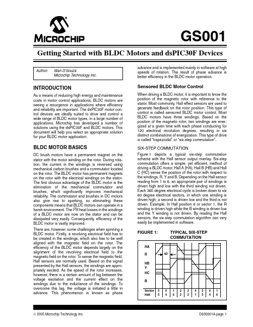
GS001INTRODUCTIONAs a means of reducing high energy and maintenance costs in motor control applications, BLDC motors are seeing a resurgence in applications where efficiency and reliability are important. The dsPIC30F motor con-trol devices are ideally suited to drive and control a wide range of BLDC motor types, in a large number of applications. Microchip has developed a number of solutions using the dsPIC30F and BLDC motors. This document will help you select an appropriate solution for your BLDC motor application.BLDC MOTOR BASICSDC brush motors have a permanent magnet on the stator with the motor winding on the rotor. During rota-tion, the current in the windings is reversed using mechanical carbon brushes and a commutator located on the rotor. The BLDC motor has permanent magnets on the rotor with the electrical windings on the stator. The first obvious advantage of the BLDC motor is the elimination of the mechanical commutator and brushes, which significantly improves mechanical reliability. The commutator and brushes in DC motors also give rise to sparking, so eliminating these components means that BLDC motors can operate in a harsh environment. The I2R heat losses in the windings of a BLDC motor are now on the stator and can be dissipated very easily. Consequently, efficiency of the BLDC motor is vastly improved.There are, however, some challenges when spinning a BLDC motor. Firstly, a revolving electrical field has to be created in the windings, which also has to be well aligned with the magnetic field on the rotor. The efficiency of the BLDC motor depends largely on the alignment of the revolving electrical field to the magnetic field on the rotor. To sense the magnetic field, Hall sensors are normally used. Based on the signal presented by the Hall sensors, the windings are appro-priately excited. As the speed of the rotor increases, however, there is a certain amount of lag between the voltage excitation and the current effect on the windings due to the inductance of the windings. To overcome this lag, the voltage is initiated a little in advance. This phenomenon is known as phase advance and is implemented mainly in software at high speeds of rotation. The result of phase advance is better efficiency in the BLDC motor operation. Sensored BLDC Motor ControlWhen driving a BLDC motor, it is important to know the position of the magnetic rotor with reference to the stator. Most commonly, Hall effect sensors are used to generate feedback on the rotor position. This type of control is called sensored BLDC motor control. Most BLDC motors have three windings. Based on the position of the magnetic rotor, two windings are ener-gized at a given time with each phase conducting for 120 electrical revolution degrees, resulting in six distinct combinations of energization. This type of drive is called “trapezoidal” or “six-step commutation”.SIX-STEP COMMUTATIONFigure1 depicts a typical six-step commutation scheme with the Hall sensor output overlay. Six-step commutation offers a simple, yet efficient, method of driving a BLDC motor. Hall A (HA), Hall B (HB) and Hall C (HC) sense the position of the rotor with respect to the windings, R, Y and B. Depending on the Hall sensor reading from 1 to 6, an appropriate pair of windings is driven high and low with the third winding not driven. Each 360 degree electrical cycle is broken down to six 60 degree electrical sectors, in which one winding is driven high, a second is driven low and the third is not driven. Example: In Hall position 6 or sector 1, the R winding is driven high while the B winding is driven low and the Y winding is not driven. By reading the Hall sensors, the six-step commutation algorithm can very easily be implemented in software.FIGURE 1:TYPICAL SIX-STEPCOMMUTATIONAuthor:Stan D’SouzaMicrochip Technology Inc.HARHBYHCB5 501234501 46231546Sector Hall 60°Getting Started with BLDC Motors and dsPIC30F Devices© 2005 Microchip Technology Inc.DS93001A-page 1GS153DS93001A-page 2© 2005 Microchip Technology Inc.DRIVING SENSORED BLDC MOTORS WITH A SINUSOIDAL VOLTAGEWhen it is rotated like a generator, a BLDC motor creates a sinusoidal voltage output (120 degrees apart)in all three phase windings. So the “natural” drivers for a BLDC motor are three sinusoidal voltages at 120degrees apart. The six-step commutation normally works very efficiently in most BLDC applications.However, in some applications, the DC switching of the PWM drive voltage used in six-step commutation some-times causes a phenomenon known as torque ripple.T orque ripple typically manifests as a low-frequency rumble in some systems.An alternative to the six-step method is to feed a PWM driven sine wave to the three phases (at 120 degrees apart) using a Space Vector Modulation (SVM)technique. This method is just as efficient as six-step commutation and delivers uniform torque to the load.Microchip is developing an application note on this technique.Sensorless BLDC Motor ControlSensors add cost to a BLDC motor application. Also,sensors need to be adjusted during the manufacturing process. In quite a few applications, however, the need to find the exact position of the rotor is not necessary.Fan blowers and compressor motors are typical appli-cations which run at a constant or limited speed range.In these applications, the back EMF detected on the third unexcited winding can be used to switch the PWM commutation of the motor windings.Figure 2 shows a typical sensorless commutation diagram. In this method, the back EMF voltage on the winding that is not driven in each sector is monitored.When this voltage crosses the imaginary “half-point” or “zero-crossing” line, zero crossing is detected. The algorithm now knows that it is in the center of the sector and has 30 electrical degrees remaining to do the next commutation. The time taken for each sector (60degrees) is known as, say T60. When the zero-crossing point is detected, a timer is loaded with half the value of T60. When this timer times out, an interrupt is generated and the next winding commutation is implemented. This method of control is called sensorless control of a BLDC motor.For example, in Sector 1, the Y winding is monitored for zero crossing. When that transition occurs, the timer is loaded with half the T60 time in a timer. When that timer times out, the windings are commutated as described earlier. That is, Y is driven high, B is kept at low and R is not driven.Microchip has developed two application notes on sen-sorless BLDC control: AN901, “Using the dsPIC30F for Sensoreless BLDC Control” and AN992, “Sensorless BLDC Motor Control Using dsPIC30F2010”.FIGURE 2:TYPICAL SENSORLESS COMMUTATION5511234SECTOR000R YBT60T30GS153dsPIC30F APPLICATION NOTESThe following are some applications notes on BLDC motor control with the dsPIC30F that will help you jump start your BLDC motor control projectAN957, “Sensored BLDC Motor Control Using dsPIC30F2010”This application note describes a simple open and closed-loop solution to control a sensored BLDC motor using a 28-pin dsPIC30F2010. The solution described uses the six-step commutation method described above to rotate and control the sensored BLDC motor. The hardware platform used is the PICDEM™ MC LV Board. With minor modifications, this application note can be used with any other hardware platform from Microchip (see the following section on motor control boards). The firmware, with minor modifications, can also be used with any motor control dsPIC30F device. The dsPIC30F2010 is ideally suited for this application due to on-chip availability of the motor control PWM, Hall sensor and QEI input modules and the ability of the DSP engine to compute multiple PID control loops. AN901, “Using the dsPIC30F for Sensorless BLDC Control”This application note describes how to implement sensorless control of a BLDC motor using the back EMF detection technique mentioned above. The back EMF voltage is attenuated and fed to the ADC inputs of the dsPIC® Digital Signal Controller (DSC). The high-speed ADC is then used to detect the zero crossing. This tech-nique provides a very efficient control method for starting and running a sensorless BLDC motor with a minimum of components. The hardware used is a dsPICDEM™MC1 Motor Control Development Board used in con-junction with either a dsPICDEM MC1L 3-Phase Low-Voltage Power module or a dsPICDEM MC1H 3-Phase High-Voltage Power module.A dsPIC30F6010 device is used on the MC1 board in this application. The application note describes in detail how to start and run a sensorless BLDC motor. The control method, however, is general enough to work with any BLDC motor available in the market. Details are provided to assist you in configuring the 45 param-eters needed to start and run the BLDC motor. All 45 of these user parameters can be set using the LCD and push buttons available on the MC1 development board. The firmware supports four different control modes and two starting modes. The hardware drive section is connected via a 37-pin D-type connector to either a high-voltage or low-voltage power module, which allows for BLDC motors that can operate in the voltage range from 10 to 400 VDC. The firmware can also be modified to work with any motor control dsPIC30F device.The dsPIC30F6010 is ideally suited for this application because it includes on-chip motor control PWM, Hall sensor and QEI input modules, along with a fast ADC required to sample the back EMF and detect zero crossing. A powerful DSP engine is available to compute multiple PID control loops.AN992, “Sensorless BDLC Motor Control Using dsPIC30F2010”This application note takes the application described in AN901 one step further and provides a low-cost, yet efficient, implementation on the smallest dsPIC30F motor control device available, namely the 28-pin dsPIC30F2010 with 12 Kbytes of program memory and 512 bytes of RAM. The hardware is simplified and uses the stand-alone PICDEM™ MC LV board as the hardware platform.Because the PICDEM MC LV board has no LCD and the dsPIC30F2010 has limited I/O, the 45 user param-eters are set using a PC via the serial port and a HyperTerminal link.The PICDEM MC LV only supports voltages from 10 to 40 VDC, hence, only low-voltage BLDC motors are able to run on this board. However, the technique used in this application can be extrapolated. If higher voltage and current drivers are provided to support higher volt-age and current, then a similar, but modified hardware can be used to run BLDC motors from 40V to 400V DC. The dsPIC30F2010 is ideally suited for this application. It includes on-chip motor control PWM, Hall sensor and QEI input modules, along with a fast ADC to sample the back EMF and detect zero crossing. A powerful DSP engine is available to compute multiple PID control loops.© 2005 Microchip Technology Inc.DS93001A-page 3GS153DS93001A-page 4© 2005 Microchip Technology Inc.dsPIC30F HARDWARE MODULES TO CONTROL BLDC MOTORSMicorchip offers a number of hardware tools to help you implement your own BLDC motor control solution.FIGURE 3:PICDEM™ MC LV BOARDPICDEM MC LV BoardThis board offers a self-contained, low-voltage platform (Figure 3) that supports all 28-pin motor control dsPIC30F devices, including the dsPIC30F2010,dsPIC30F3010 and the dsPIC30F4012. Hardware sup-port for sensored, as well as sensorless, BLDC motors is available on this board. The factory shipped board supports a motor voltage of 24V; however, the hardware can support voltages from 10V to 40V at motor currents of up to 4 Amps.A serial port is available to communicate with an external source. An MPLAB ® ICD 2 In-Circuit Debug-ger connection is available for programming and debugging purposes. A potentiometer is available for speed control, along with two switches for start/stop control.On-board power drivers support direct drive to the BLDC motor. A low-side power resistor supplies current and Fault feedback to the dsPIC DSC. The “PICDEM ™MC LV Development Board User’s Guide” (DS51554)provides details on the use of this board.dsPICDEM MC1 Motor Control Development BoardThe dsPICDEM MC1 Motor Control Development Board (Figure 4), is a general purpose development board that uses a dsPIC30F6010 to control a wide range of motor control applications, including sensored and sensorless BLDC motors. Serial RS-232 and CAN ports are supported, along with an ICD 2 In-Circuit Debugger connection for programming and debugging purposes.A two-lines by 20-character LCD is used along with four LEDs for display purposes. Four push buttons and two potentiometers are available for data entry and feed-back. Spare analog and digital pins are made available on two header banks.No drivers are available on the board, so the MC1board must be connected to an external drive system.A 37-pin D-type connector is used to connect the MC1board to a dsPICDEM MC1H 3-Phase High-Voltage module (Figure 5) or dsPICDEM MC1L 3-Phase Low-Voltage module (Figure 6). The D-type connector connects to external circuitry via opto isolators, thus allowing for a safe, electrically isolated drive to high voltage (400 VDC).The dsPICDEM MC1 Motor Control Development Board can be used with a dsPICDEM MC1H 3-Phase High-Voltage Power module to drive a high-voltage BLDC motor. Refer to the “dsPICDEM ™ MC1 Motor Control Development Board User’s Guide” (DS70098)for full details on the capabilities and functions available on this board.FIGURE 4:dsPICDEM™ MC1 MOTOR CONTROL DEVELOPMENT BOARD[Insert photo of dsPICDEM MC1 Board]© 2005 Microchip Technology Inc.DS93001A-page 5GS153FIGURE 5:dsPICDEM™ MC1H 3-PHASE HV MODULEdsPICDEM MC1H 3-Phase High-Voltage Power ModuleThe high-voltage module (Figure 5) connects to an MC1 board to form a high-voltage BLDC motor control system. The dsPICDEM MC1H 3-Phase High-Voltage Power module offers high-voltage isolation, as well as Fault, overcurrent and overvoltage protection. Each phase is monitored with fast current sensors and a robust latching network to disable the outputs in case any Fault condition occurs. This protection is neces-sary during code development and prevents accidental destruction of the drive circuitry due to inadvertent software issues.The high-voltage module rectifies a single-phase wall input voltage of 110 VAC to generate a DC bus voltage of 165 VDC. Alternatively, it can also rectify an input wall voltage of 220 VAC to get a DC bus voltage of 330VDC. This DC bus voltage is then converted to drive a 3-phase motor.The hardware can be used to drive ACIM and BLDC motors. For complete details on the features and capabilities of this module, refer to the “dsPICDEM ™MC1H 3-Phase High-Voltage Power Module User’s Guide” (DS70096).FIGURE 6:dsPICDEM™ MC1L 3-PHASE LV MODULEdsPICDEM MC1L 3-Phase Low-Voltage Power ModuleThe low-voltage module (Figure 6) connects to an MC1board to form a low-voltage BLDC motor control system. The dsPICDEM MC1L 3-Phase Low-Voltage Power module offers voltage isolation, along with Fault,overcurrent and overvoltage protection. Each phase is monitored with fast current sensors and a robust latch-ing network to disable the outputs in case any Fault condition occurs. This protection is necessary during code development and prevents accidental destruction of the drive circuitry due to inadvertent software issues. DC voltage is supplied externally from a power supply.This DC bus voltage is then converted to drive a 3-phase motor.The hardware can drive 3-phase low-voltage BLDC motors. For more details on the features and cap-abilities of this module, refer to the “dsPICDEM ™MC1L 3-Phase Low-Voltage Power Module User’s Guide (DS70097).GS153DS93001A-page 6© 2005 Microchip Technology Inc.DIFFERENT dsPIC30F BASEDHARDWARE PLATFORMS FOR BLDC MOTOR CONTROLYou can use the Selection Summary (Table 1) to select different Microchip hardware platforms for specific application needs. Note that although there are alimited number of dsPIC DSC devices supported on a given hardware platform, you can build a daughter board based on the motor control dsPIC30F device needed for your application and plug it into the avail-able socket or header pins on the PICDEM MC LV or MC1 development boards.TABLE 1:SELECTION SUMMARYORDERING INFORMATION AND NUMBERSPICDEM™ MC LV Development Board: DM183021Power Supply (optional): AC002013Motor with cables: AC300020“PICDEM ™ MC LV Development Board User’s Guide” (DS51554)dsPICDEM™ MC1 Motor Control Development Board: DM300020“dsPICDEM ™ MC1 Motor Control Development Board User’s Guide” (DS70098)dsPICDEM™ MC1H 3-Phase High-Voltage Power Module: DM300021“dsPICDEM ™ MC1H 3-Phase High-Voltage Power Module User’s Guide” (DS70096)dsPICDEM™ MC1L 3-Phase Low-Voltage Power Module: DM300022“dsPICDEM ™ MC1L 3-Phase Low-Voltage Power Module User’s Guide” (DS70097)BLDC Motor Type Operating Voltage Range (VDC)Power Range (Watts)ApplicationNote Hardware Platform RecommendationsSupported dsPIC30F Devices Sensored10 to 4050 to 200AN957PICDEM™ MC LVdsPIC30F2010 dsPIC30F3010 dsPIC30F4012Sensored 40 to 400Up to 800AN957MC1 and High-Voltage Power module dsPIC30F6010Sensored 10 to 48Up to 600AN957MC1 and Low-Voltage Power module dsPIC30F6010Sensorless10 to 40AN992PICDEM MC LVdsPIC30F2010dsPIC30F3010dsPIC30F4012Sensorless 40 to 400Up to 800AN901MC1 and High-Voltage Power module dsPIC30F6010Sensorless 10 to 48Up to 600AN901MC1 with Low-Voltage Power module dsPIC30F6010Sensorless40 to 400As per user’s designAN992PICDEM MC LV (user modified for high voltage)dsPIC30F2010dsPIC30F3010dsPIC30F4012© 2005 Microchip Technology Inc.Advance InformationDS93001A-page 7Information contained in this publication regarding device applications and the like is provided only for your convenience and may be superseded by updates. It is your responsibility to ensure that your application meets with your specifications.MICROCHIP MAKES NO REPRESENTATIONS OR WAR-RANTIES OF ANY KIND WHETHER EXPRESS OR IMPLIED,WRITTEN OR ORAL, STATUTORY OR OTHERWISE,RELATED TO THE INFORMATION, INCLUDING BUT NOT LIMITED TO ITS CONDITION, QUALITY , PERFORMANCE,MERCHANTABILITY OR FITNESS FOR PURPOSE .Microchip disclaims all liability arising from this information and its use. Use of Microchip’s products as critical components in life support systems is not authorized except with express written approval by Microchip. No licenses are conveyed,implicitly or otherwise, under any Microchip intellectual property rights.TrademarksThe Microchip name and logo, the Microchip logo, Accuron, dsPIC, K EE L OQ , micro ID , MPLAB, PIC, PICmicro, PICSTART, PRO MATE, PowerSmart, rfPIC, and SmartShunt areregistered trademarks of Microchip Technology Incorporated in the U.S.A. and other countries.AmpLab, FilterLab, Migratable Memory, MXDEV, MXLAB, PICMASTER, SEEVAL, SmartSensor and The Embedded Control Solutions Company are registered trademarks of Microchip Technology Incorporated in the U.S.A.Analog-for-the-Digital Age, Application Maestro, dsPICDEM, , dsPICworks, ECAN, ECONOMONITOR, FanSense, FlexROM, fuzzyLAB, In-Circuit SerialProgramming, ICSP , ICEPIC, Linear Active Thermistor, MPASM, MPLIB, MPLINK, MPSIM, PICkit, PICDEM, , PICLAB, PICtail, PowerCal, PowerInfo, PowerMate, PowerTool, rfLAB, rfPICDEM, Select Mode, Smart Serial, SmartTel, Total Endurance and WiperLock are trademarks of Microchip Technology Incorporated in the U.S.A. and other countries.SQTP is a service mark of Microchip Technology Incorporated in the U.S.A.All other trademarks mentioned herein are property of their respective companies.© 2005, Microchip Technology Incorporated, Printed in the U.S.A., All Rights Reserved.Printed on recycled paper.Note the following details of the code protection feature on Microchip devices:•Microchip products meet the specification contained in their particular Microchip Data Sheet.•Microchip believes that its family of products is one of the most secure families of its kind on the market today, when used in the intended manner and under normal conditions.•There are dishonest and possibly illegal methods used to breach the code protection feature. All of these methods, to ourknowledge, require using the Microchip products in a manner outside the operating specifications contained in Microchip’s Data Sheets. Most likely, the person doing so is engaged in theft of intellectual property.•Microchip is willing to work with the customer who is concerned about the integrity of their code.•Neither Microchip nor any other semiconductor manufacturer can guarantee the security of their code. Code protection does not mean that we are guaranteeing the product as “unbreakable.”Code protection is constantly evolving. We at Microchip are committed to continuously improving the code protection features of our products. Attempts to break Microchip’s code protection feature may be a violation of the Digital Millennium Copyright Act. If such acts allow unauthorized access to your software or other copyrighted work, you may have a right to sue for relief under that Act.Microchip received ISO/TS-16949:2002 quality system certification for its worldwide headquarters, design and wafer fabrication facilities in Chandler and Tempe, Arizona and Mountain View, California in October 2003. The Company’s quality system processes andprocedures are for its PICmicro ® 8-bit MCUs, K EE L OQ ® code hopping devices, Serial EEPROMs, microperipherals, nonvolatile memory and analog products. In addition, Microchip’s quality system for the design and manufacture of development systems is ISO 9001:2000 certified.AMERICASCorporate Office2355 West Chandler Blvd. Chandler, AZ 85224-6199 Tel: 480-792-7200Fax: 480-792-7277 Technical Support: Web Address: AtlantaAlpharetta, GATel: 770-640-0034Fax: 770-640-0307BostonWestborough, MATel: 774-760-0087Fax: 774-760-0088 ChicagoItasca, ILTel: 630-285-0071Fax: 630-285-0075DallasAddison, TXTel: 972-818-7423Fax: 972-818-2924DetroitFarmington Hills, MITel: 248-538-2250Fax: 248-538-2260 KokomoKokomo, INTel: 765-864-8360Fax: 765-864-8387Los AngelesMission Viejo, CATel: 949-462-9523Fax: 949-462-9608San JoseMountain View, CATel: 650-215-1444Fax: 650-961-0286 TorontoMississauga, Ontario, CanadaTel: 905-673-0699Fax: 905-673-6509ASIA/PACIFICAustralia - SydneyTel: 61-2-9868-6733Fax: 61-2-9868-6755China - BeijingTel: 86-10-8528-2100Fax: 86-10-8528-2104China - ChengduTel: 86-28-8676-6200Fax: 86-28-8676-6599China - FuzhouTel: 86-591-8750-3506Fax: 86-591-8750-3521China - Hong Kong SARTel: 852-2401-1200Fax: 852-2401-3431China - ShanghaiTel: 86-21-5407-5533Fax: 86-21-5407-5066China - ShenyangTel: 86-24-2334-2829Fax: 86-24-2334-2393China - ShenzhenTel: 86-755-8203-2660Fax: 86-755-8203-1760China - ShundeTel: 86-757-2839-5507Fax: 86-757-2839-5571China - QingdaoTel: 86-532-502-7355Fax: 86-532-502-7205ASIA/PACIFICIndia - BangaloreTel: 91-80-2229-0061Fax: 91-80-2229-0062India - New DelhiTel: 91-11-5160-8631Fax: 91-11-5160-8632Japan - KanagawaTel: 81-45-471- 6166Fax: 81-45-471-6122Korea - SeoulTel: 82-2-554-7200Fax: 82-2-558-5932 or82-2-558-5934Malaysia - PenangTel:011-604-646-8870Fax:011-604-646-5086Philippines - ManilaTel: 011-632-634-9065Fax: 011-632-634-9069SingaporeTel: 65-6334-8870Fax: 65-6334-8850Taiwan - KaohsiungTel: 886-7-536-4818Fax: 886-7-536-4803Taiwan - TaipeiTel: 886-2-2500-6610Fax: 886-2-2508-0102Taiwan - HsinchuTel: 886-3-572-9526Fax: 886-3-572-6459EUROPEAustria - WeisTel: 43-7242-2244-399Fax: 43-7242-2244-393Denmark - BallerupTel: 45-4450-2828Fax: 45-4485-2829France - MassyTel: 33-1-69-53-63-20Fax: 33-1-69-30-90-79Germany - IsmaningTel: 49-89-627-144-0Fax: 49-89-627-144-44Italy - MilanTel: 39-0331-742611Fax: 39-0331-466781Netherlands - DrunenTel: 31-416-690399Fax: 31-416-690340England - BerkshireTel: 44-118-921-5869Fax: 44-118-921-5820 W ORLDWIDE S ALES AND S ERVICE04/20/05DS93001A-page 8© 2005 Microchip Technology Inc.。
BSC中文版

EVOLIUM BSC 基站控制器1 / 67上海贝尔阿尔卡特大学目录1BSC简介 (1)1.1BSC的功能 (1)1.2BSC的接口 (5)2BSC的结构特点 (7)3DSN网络 (8)3.1DSN网络的结构 (8)3.2网络地址NA(network address) (11)3.3Tunnels、Caves和cross_links (12)4Abis TSU (16)4.1TCUC(terminal control unit type C) (16)4.1.1TCUC的功能 (16)4.1.2TCUC的硬件结构 (17)4.1.3TCUC的容量 (17)4.2BIUA(base station interface unit type A) (18)4.2.1BIUA的功能 (18)4.2.2BIUA的硬件结构 (19)4.2.3BIUA的容量(Abis TSU的容量) (19)5Ater TSU (22)5.1DTCC(digital trunk control type C) (22)i / 675.1.1DTCC的功能 (22)5.1.2DTCC的映射 (23)5.1.3DTCC的硬件结构 (25)5.2ASMB(Ater submultiplexer type B) (25)5.2.1ASMB的功能 (25)5.2.2ASMB板的硬件结构 (26)5.2.3ASMB的容量(Ater TSU的容量) (26)6Common TSU (27)6.1SYS_CPR (28)6.2OSI_CPRC (28)6.3BC_CPRC (29)6.4CPR板的硬件结构 (30)7广播、时钟和告警系统 (31)7.1广播总线分配系统 (31)7.2时钟产生与分配系统 (32)7.2.1系统时钟的产生 (32)7.2.2系统时钟的分配 (34)7.2.3机架时钟的再生与分配 (34)7.3外部告警的扫描 (35)8TSCA (36)8.1TSCA的功能 (36)8.2Qmux地址 (37)8.3Qmux总线 (38)8.4TSCA板的硬件结构 (39)9BSC的配置 (40)9.1BSC机架的配置 (41)9.2BSC机架的结构 (44)9.3BSC的容量 (48)9.4CPRC/DISK的映射 (48)10电路板灯的状态 (50)附录:练习题 (57)iii / 671BSC简介1.1BSC的功能BSC作为无线子系统部分的核心,具有对一个或多个BTS进行控制的功能,它主要负责无线网络资源的管理、小区配置数据管理、功率控制、定位和切换等,是个很强的业务控制点,在BSS内部起着控制器和话务集中器的作用。
资源编码及相关要求

各类实体的编码规则—光设施类
通常的光设施主要有ODF、光交接箱、光分纤盒、光终端盒和OBD(光分路 器)、光缆。这些设施都必须在实地具备编码或挂牌。 1、编码规则 ODF:局站+ODF+所在列架号(例,ZG.NMJT01/ODF01-02) 光交接箱:局站+ GJ+3位数字 (例,ZG.NMJ/GJ001) 光分纤(终端)盒:局站+ GF(GB)+3位数字 (例,ZG.NMJ/GF001) OBD:光交(光分)+OBD+3位数字(例,ZG.NMJ/GJ001/OBD001) 光缆:通常用起点+重点+类型+2位数字表示。 (例,ZG.NMJT01-GJ001/ZGG01)
资源编码规范及相关要求
赣州电信网络资源中心
2012-4-19
目录
1、资源编码规范 2、现场标识要求 3、竣工资料简要要求
资源编码规范基本原则
资源规范编 码的作用 网络资源数据的规范化与标准化是网络资源集中管理的基础,网 络资源对象的命名定义了资源对象在网络中的唯一标识。
总体规则
资源对象的命名一般由若干资源对象特征的描述信息以及编号构成 。在资源对象的命名格式中,其中构成命名的部分特征字段可以是中文 字符或者是与中文字符意义相同的非中文字符,在确定的命名规则下, 部分字段采用不同形式的字符可以形成的不同形式的命名表达方式。
光分纤箱
光网络箱(即二级光交) 光交接箱
各类实体的编码规则—电交设施及路由类
1、编码规则 MDF:局站+MDF+3位数字 (例,ZG.NMJ/MDF001) 电交接箱:局站+ J+主干电缆号+序号 (例,ZG.NMJ/J0101) 分线盒:电交编码+DP+分线盒关联电缆对应的端子(例, ZG.NMJ/J0101/DP110110) 电杆:电交编码+杆路号+3位数字(例,ZG.NMJ/J0101/01P001) 人手井:局站+#+4位数字。 (例,ZG.NM/#0001)
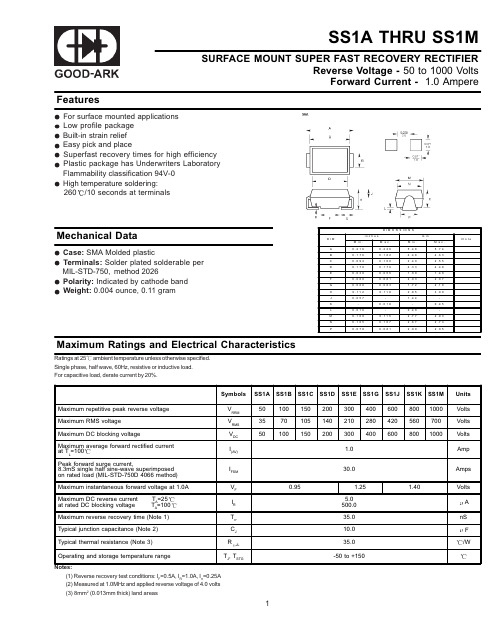
SS1D中文资料
TJ, TSTG
1
元器件交易网
RATINGS AND CHARACTERISTIC CURVES
2
0.95
1.25 5.0 500.0 35.0 10.0 35.0 -50 to +150
1.40
Volts A nS F /W
Maximum reverse recovery time (Note 1) Typical junction capacitance (Note 2) Typical thermal resistance (Note 3) Operating and storage temperature range
元器件交易网
SS1A THRU SS1M
SURFACE MOUNT SUPER FAST RECOVERY RECTIFIER Reverse Voltage - 50 to 1000 Volts Forward Current - 1.0 Ampere
Features
For surface mounted applications Low profile package Built-in strain relief Easy pick and place Superfast recovery times for high efficiency Plastic package has Underwriters Laboratory Flammability classification 94V-0 High temperature soldering: 260 /10 seconds at terminals
GS-101D油色谱分析仪说明书

变压器油色谱分析仪使用说明书上海菲柯特电气科技有限公司敬告用户:欢迎贵单位使用本公司最新推出变压器油专用油气相色谱仪。
使用前请阁下详细阅读本说明书。
目录一、产品概述 (1)(一)、主要技术指标 (1)(二)、主要性能特点 (2)(三)、工作条件 (2)二键盘使用说明 (3)(一)、面板与键盘 (3)(二)、键盘与显示...........................................................................3-4 (三)、开机 (5)(四)、键盘操作..............................................................................5-7 三、绝缘油分析 (8)(一)、分离流程 (8)(二)、热导检测器 (9)(三)、氢焰检测器 (9)(四)、转化炉 (10)(五)、操作条件的选择 (10)四、柱分流柱系统流程图 (11)五、变压器油专用油气相色谱仪整套系统配置表 (12)一、产品概述变压器油专用油气相色谱仪是按照电力系统《绝缘油中溶解气体组分含量测定法(色谱法)》要求,采用微机自动控制、全键盘操作、大屏幕液晶显示,具有控温精度高、性能稳定可靠、灵敏度高、重复性好等特点。
该仪器采用双柱并联分流系统,配有TCD和双FID及甲烷转化炉,能一次进样实现油中溶解气体九组分(H2、O2、N2、CH4、C2H2、C2H4、C2H6、CO、CO2)的全分析。
仪器可用于电力系统油气设备内部故障检测,氢冷发电机冷却介质分析、六氟化硫杂质分析、锅炉烟气分析、天然气分析和环境监测分析等。
既可作专用分析,又可作通用分析,因而它成为石油、化工、矿山等系统作为气体分析的最有效设备。
(一)、主要技术指标1、温度控制①温控范围:柱室:室温+15℃—399℃汽化室:室温+30℃—399℃转化炉:室温+30℃—399℃热导检测器:室温+30℃—399℃氢焰检测器:室温+30℃—399℃②控温精度:±0.1℃2、热导检测器①灵敏度:对氢最小检测浓度≥5μl/L②噪声:≤0.05mv③漂移:≤0.15mv/30min3、氢焰检测器①对烃类最小检测浓度≥0.1μl/L②对CO、CO2最小检测浓度≤5μl/L③噪声:≤0.05mv④漂移:≤0.15mv/30min4、整机启动时间不大于3小时。
J D I G I T A L C D 控制器操作手册说明书

Read carefully!ENGLISH VersionThis manual contains important safety informations about installation and use of this equipment. Ignoring this informations could result in injuries or damages.It is strictly forbidden to use this equipment withradioactive chemicals!IndexIndexGENERAL DESCRIPTION (4)CONTROL PANEL (4)ELECTRICAL WIRINGS: (5)VIEW ON MENU (6)SETTING SETPOINTS: 1)SETPN (6)Out mA (7)CALIBRATION: 2)CALIB (8)DELAY: 3) Delay (9)RESERVED: 4) Reserv (9)PASSWORD SETUP: 1) New Pw (10)STANDBY SETUP: 2) Stand (10)MANUAL WORKING MODE: 3) Serv (11)ERROR MESSAGES (11)3100 uS1on 2--UP” key“DOWN” key5ELECTRICAL WIRINGS:1 - 2: Power Supply (24VAC* or 115VAC* or 230VAC*). * See instrument's label 3-4: Setpoint 1 output - free contact.5-6: Setpoint2 output - free contact.7-8: Conductivity probe.9-10: Temperature compensation probe. 9 (GND) ; 10 (NTC).11-12: Current output (0÷20mA o 4÷20mA) proportional to read value. 11(-) ; 12 (+).13-14-15-16: See the following paragraph.Note : POWER SUPPLY FUSE PROTECTED (0,2A)Conductivity probes with built in temperature compensation (for example ECDCC/1) have 4 wires +shield.Connect red and black wires to conductivity blocks.Connect white and green wires to temperarure blocks.Connect shield to ground 9 (GND). “SEPR” CONFIGURATION.The instrument is set to work without a proximity sensor. If needed, proximity sensor turns the instrument into stand-by mode if there isn’t flow. Instrument’s display shows “NO FLOW”.Connect “SEPR” to blocks 13(blue), 15(black), 16(brown). Connect together block 14 with block 13.To work without a “SEPR” and with the same functionality use blocks 15 and 16 as a free contact.Connect together block 14 with block 13.Using “SEPR” or the free contact, two instruments can be controlled. Connect block 14 and 15 from master instrument to another instrument “J Digital” (slave). Finally follows the previous described connections for the master instrument.Installation1 2 3 4 5 6 7 8 9 10 11 12 13 14 15 16InstallationVIEW ON MENUMake connections and plug the instrument. Instrument’s version message on display confirms that the instrument is on. The display shows also the probe reading status and if setpoints are active. Press “E” for about 4 seconds to enter into setup menu.Note: During setup the instrument is in “Stand-by” mode. If user doesn’t press any key for one minute the instrument will return to normal working mode.To enter into setup menu, a password is needed. If this the first time that user enters into this menu or if the password is not changed, simply press “E”. Use “UP” and “DOWN” keys to scroll.“MAIN” menu is configured as follows:1)Setup: This menu is divided into 1)Setpn ; 2)Calib ; 3)Delay.2)Param: This menu is divided into 1)New Pw ; 2)Stand.3)Serv.: service mode.SETTING SETPOINTS: 1)SETPN“Out 1” and “Out 2” are relay’s driven outputs. The instrument can be programmed to operate in “On/ Off” mode or “Proportional” mode.“Proportional” mode can be selected in % between 10 and 100.Select “SETUP” from “MAIN” menu. Select “SETPN” and press “E”. The display shows:Setpoint1) Out 1Pressing “UP” or “DOWN” key the display will show in succession:Setpoint1) Out 1Setpoint2) Out 2Setpoint3) Out mASelect the setpoint to set (Out 1 or Out 2) using “UP” and “DOWN” keys, press “E” to confirm. “Out mA” allows to set the current output based on two Conductivity values. In the next example setpoint 1 (Out 1) has been set.6SETUP The instrument shows:1a) ->OFF1100uSPressing twice “RIGHT” key the display will show:1b) ->ON1000uS“1a)” and “1b)” are working range values. Every range is set by a value that operates relay output. Using default values, the setpoint 1 will drive a pump that will increase the conductivity value. The pump will switch on for uS values minor than 1000uS and switch off when reaches 1100uS: this is the ON/OFF working mode. The difference between the two uS (1100 e 1000) is called HYSTERESIS. T o avoid damaging the relay do not set Hysteresis under 100uS.PROPORTIONAL mode. The output relay is modulated (ON/OFF) depending on uS values set in 1a) and 1b). Ex.: Proportional mode between 1100uS (0%) and 1000uS (100%). In this way the relay will be on for values between 0 and 1000uS, it will be on for values higher than 1100uS. For values between 1000uS and 1100uS the relay will be on or off depending on calculated percentage.The calculation is based on a 100 seconds time. If Conductivity reaches 1030uS the relay will be on for 70 seconds and off for 30 seconds. To set the PROPORTIONAL functioning mode substitute percentual value to “ON” and “OFF”.It is not possible to enter mixed values (ex.: 100% for SP1 and ON for SP2). In this case it will not possible save them.In proportional mode the instrument doesn’t show % values for setpoints status but only if they are on or off.It is possible modify setpoint status (on,off, %) and setpoint values with RIGHT key on the function to modify and using “UP” and “DOWN” key to change the value. Enter the value and save by pressing “E” to save.Repeat sequence for setpoint 2 (OUT2).Press “E” key to exit from setpoint setting. The display will show “SetPoint Saved” and it return to the previous menu.Out mAThis function allows to program the current output for driving a metering pump or a chart recorder. It is possible to program in 0÷20mA mode or 4÷20mA mode in the working range between 0 and 2000uS. The current output and the working range may be modified. Ex.: it is possible to set 4mA at 0uS and 20mA at 1000uS. In this case, if you connect a metering pump it will dose at the maximum flow at 0uS. The pump will reduce the flow when Conductivity decrease and it will stop at 1000uS. If you connect a chart recorder, a graphic curve will be printed. Use “UP” and “DOWN” keys to change these settings. Press “RIGHT” key to scroll through the options. Press “E” to confirm.7SETUPCALIBRATION: 2)CALIBChoose “CALIB” from “Setup”. Display shows:Calib1)ZeroPress “UP” key. Display shows:Calib2) SlopeZero calibration.When display shows “1) Zero” press “E” to enter into zero calbration procedure. Display shows: R --.--uSC 0.00uSTo calibrate probes (K1) as mod. ECDIC/1 remove it from probe holder and calibrate it to air. Wait until “R” value is stable. ATTENTION: IT IS NOT NECESSARY THAT “R” VALUE WILL BE THE SAME OF “C” VALUE. Press “E” to confirm. Display shows:Calibr.Success.Slope calibration.When display shows “2) Slope” press “E” to enter into slope calbration procedure. Display shows: Temp Cal25°CThis is the buffer solution or the plant temperature. It is not possible modify this value. Press “E” to continue. The instrument will show:Comp.3%This is the temperature compensation coefficient. Modify this value according with the table on the buffer solution / chemical product bottle, using “UP” and “DOWN” keys. Press “E” to confirm. The instrument will show:R --.-- uSC 84uSIf you are using a 84 uS (or a different one compatible with working range) buffer solution press “E”otherwise enter the buffer solution value used by “UP” and “DOWN” keys and press “E”. Connect the probe to the instrument. Insert the probe tip into the 84 uS buffer solution and wait until R value (read value) is stablized and then press “E” to confirm the calibration.ATTENTION: IT IS NOT NECESSARY THAT “R” VALUE WILL BE THE SAME OF “C” VALUE.If the procedure is correct the instrument will show a confirmation message otherwise a numbered error message will be displayed (see table on page 10). Is an error occurred, repeat the procedure.8SETUP DELAY: 3) DelayIt’s possible to set an activation delay for each output when the instrument reaches the setpoint values. Default value is set to 0. Select “DELAY” from “SETUP” menu. The instrument will show:OUT110 Sec.Press “RIGHT” key. The instrument will show:OUT25 Sec.Delay time can be set from 0 (no delay) to 60 seconds. Press “E” to confirm. The display will show the confirmation message “DELAYS SAVED”.9PARAMPASSWORD SETUP: 1) New PwTo avoid undesired access to the instrument a 4 number password may be set. Using “UP” or “DOWN” keys, from “Param” menu choose “1) New Pw”, press “E” to confirm. The display shows: NEW PW-> 0 0 0 0Use “UP” and “DOWN” keys to modify th first digit. Use “RIGHT” key to go on the next digit. Press “E” to confirm. The instrument will show the new password for 2 seconds and then will return to the main menu.STANDBY SETUP: 2) StandFor a good electrodes polarization a delayed startup (every time the instrument is powered) may be set. Select “2)STAND” from “Param” menu. The display will show:STANDBY-> 02 Sec.It is possible to set the delay using “UP” and “DOWN” keys. The time can be set between 0 (no delay) to 60 seconds. Press “E” to confirm. The display will show the confirmation message “Stand-by Saved”for 2 seconds.10SERV. MANUAL WORKING MODE: 3) Serv.This function allows to manual control the external relays contact (SP1 / SP2).The display will show 1 or 2 to show the selected setpoint/output. The output status can be set “ON”or “OFF” using “UP” key for SP1 and “DOWN” key for SP2. “ON” is the status of N.O contact closed and N.C. contact open. “OFF” is the status of N.O. contact open and N.C. contact closed.ERROR MESSAGESIf the display shows an error message, use the following table:ERROR 1:Buffer solution error during calibration. Try again using adifferent buffer solution.ERROR 2:Buffer solution read error during calibration. Try again using adifferent buffer solution.ERROR 3:N/AERROR 4:Offset error. Verify sample and repeat procedure.11When dismantling an instrument please separate material types and send them according to local recycling disposal。
物联网中英文词汇对照表

扩大器
Amplitude-Shift Keyi ng
ASK
幅移键控
Antenna
天线
An ti-Collisio n
防碰撞
Application Family Identifier
AFI
应用系列产品识别码
Application Identifier
应用识别码
Applicati on Level Events
物联网词汇中英对照表
英文名称
英文缩与
中文翻译
The Internet of Things
IOT
物联网
1-Bit Transpon der
1位询答器
2D Matrix Code
矩阵式二维条形码
2D Sea nner
二维条形码扫描枪
2D Stacked Code
堆栈式二维条形码
Abstract Data Model Layer
GSMP
全球标准管理程序
Global Tag
GTAG
全球标准标签
Global Trade Item Number
GTIN
全球交易品项识别代码
Han dheld Reader
手持式读取器
Hash Lock
杂凑锁
Hash-cha in
杂凑链
Header
标头
Health&Life Scie nce
HLS
健康医疗产业
EPCglobal
EPCglobal Chi na
EPCglobal中国
EPCglobal Network
EPCglobal网络
Erasure Correction
GS1G中文资料
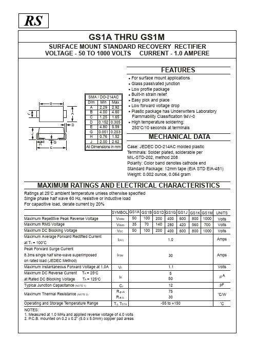
MAXIMUM RATINGS AND ELECTRICAL CHARACTERISTICS
Ratings at 25oC ambient temperature unless otherwise specified Single phase half wave 60 Hz, resistive or inductive load For capacitive load, derate current by 20%
B C A
D
J im Min Max A 2.29 2.92 B 4.00 4.60 1.25 1.65 C 0.152 0.305 D 4.80 5.59 E 0.051 0.203 G 0.76 1.52 H 2.00 2.62 J All Dimensions in mm
20
0.5
SINGLE PHASE HALF WAVE 60Hz RESISTIVE OR INDUCTIVE LOAD
15
0 0 25 50 75 100 125
O
10
150
175
LEAD TEMPERATURE ( C)
5
Figure 1. Typical Forward Current Derating Curve
元器件交易网
RS
GS1A THRU GS1M
SURFACE MOUNT STANDARD RECOVERY RECTIFIER VOLTAGE - 50 TO 1000 VOLTS CURRENT - 1.0 AMPERE
FEATURES
For surface mount applications Glass passivated junction Low profile package Built-in strain relief Easy pick and place Low forward voltage drop Plastic package has Underwriters Laboratory Flammability Classification 94V-0 High temperature soldering: 250oC/10 seconds at terminals
基于GS1全球统一标识系统的商品信息服务平台在电子商务中的作用

项 国际 、国家标 ; 建而成 , 台对 商品 条码 、 隹构 平 产品 属性 、 品 分类 、 产 传输 格式按 照国 际标 准 , 实行 标 准 化 后 , 过 同步 功能 , 企业 间产 品信 通 使 息迅 速链 接 成 为可能 , 可助 各贸易参 与 方通 过 协 调 一 致 的标 准 , 续 不 断地 交换 产品数 据 , 连 共享
商 业机会 。 中国商品信息 服务 平 台对各 企业 实 现
电子商务提 供了有力地 支撑服 务。
内部 局域 网, 在信息平 台建 设 上超 过 了制造 业 和
批 发业 , 只有3 .%的企 业在 网上公 布 商品信 但 88
积 极推 动了现有供 销信息交换 模 式的改 进 在传统 的零 售行业 新 品引入流 程中 , 货商 供
管 理 现 状 的调 查 表 明 , 27%的零 售 企 业 建 有 6.
平 地 竞争 , 企 业 获 取 更多 的商业机 会 i 让 平台还 有 一 个 特 别 的优 势 , 量 地供 应 方通 过 中国 商 大 品信息 服务 平台发布 信息 , 以吸 引更多 的零售 可
方访问平台, 搜寻需要的产品, 从而创造更多的
包 含商 品名 称 、 产地 、 格 等物 理 属性 , 规 以及 商
品价格、 可供给的商品数量、 供应开始时间等贸 易属性的新品单 , 填写后还 需要零售 商内部逐
级 审批 通 过 , 终 该 商品 才 可 以正 式 通 过 订 购 最 流程 向零 售商 供 货。 中国商品信息平 台的帮助 在 下, 供应 商只 要把商 品所有 的基础 信 息添 加 到平
方 电子平台
中国商 品信 息 服 务平 台是 一 个开 放 式 的 中 立 的商务 平 台, 多个买 方和 多个卖 方提供 商 品 为
条码考试资料多选题模板
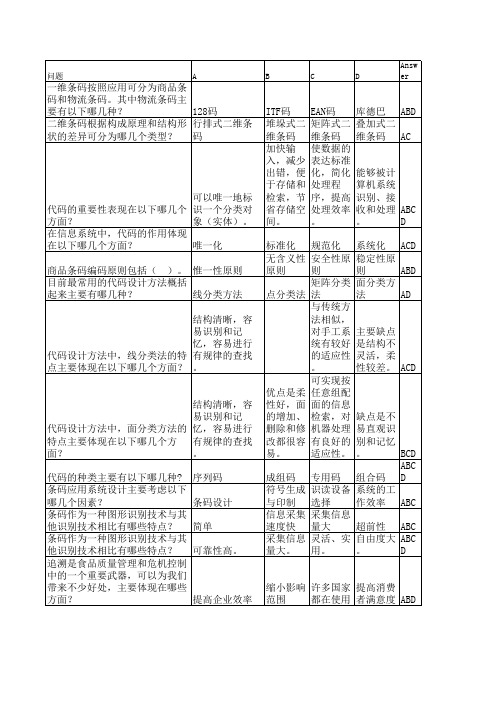
终端仿真 无线数据采集器与计算机系统的 (TELNET)连 连接方式主要有以下几种? 接 数据采集器目前主要应用在哪些 仓储及配送中 场合? 心 13位代码的条 码符号的印刷 面积超过商品 独立包装的单个零售商品,在什 标签最大表面 么情况下可申请采用8位代码结 面积的1/4或全 构? 部可印刷面积 EAN-13条码由左侧空白区、起始 符、左侧数据符、中间分隔符、 右侧数据符和( )组成。 校验符 EAN-13条码由( )右侧数据符 、校验符、终止符、右侧空白区 及供人识别字符组成。 左侧空白区 在条码符号的颜色搭配上,以下 哪些颜色可以进行搭配? 蓝条白空 条码符号的质量要求主要体现在 以下哪些方面? 下列属于矩阵式二维条码的是( )。 下列属于行排式二维条码的是( )。 物流单元标识代码采用系列货运 包装箱代码(SSCC)表示,由( )几个部分组成。 附加信息代码是标识物流单元相 关信息的代码,由( )组成。 货物托运代码由货物运输方的( )组成。 一个完整的物流单元标签包括多 个标签区段,从上到下的顺序通 常为( )。 物流单元标签的承运商区段通常 包含在装货时就已确定的信息, 如( )。
标准化 规范化 无含义性 安全性原 原则 则 矩阵分类 点分类法 法 与传统方 法相似, 对手工系 统有较好 的适应性 。 可实现按 优点是柔 任意组配 性好,面 面的信息 的增加、 检索,对 删除和修 机器处理 改都很容 有良好的 易。 适应性。
主要缺点 是结构不 灵活,柔 性较差。 ACD
缺点是不 易直观识 别和记忆 。 BCD ABC 成组码 专用码 组合码 D 符号生成 识读设备 系统的工 与印制 选择 作效率 ABC 信息采集 采集信息 速度快 量大 超前性 ABC 采集信息 灵活、实 自由度大 ABC 量大。 用。 。 D
EPSON系列票据打印机指令集

esc/pos打印指令(一) Post By:2005-5-16 1:46:00EPSON指令集打印控制命令5.1.打印控制命令5.1.1 概述BS-210BM 提供了ESC/POS命令集。
下面将对每个命令进行说明。
每个命令的说明包括格式和解释两部分。
格式部分提供了命令的ASCII码、十进制码和十六进码三种格式,解释部分描述命令的功能。
三种命令的格式是等价的,用户可按照需要选择任一种。
5.1.2 各个命令的描述格式如下:打印命令功能格式: ASCII:以标准ASCII字符序列表示十进制:以十进制数字序列表示十六进制:以十六进制数字序列表示说明:该命令功能和使用说明。
5.1.3 命令说明HT 水平制表格式: ASCII:HT十进制:09十六进制:09说明:打印位置进行到下一水平制表位置。
如果当前打印位置超过了最后一个水平制表位置,则HT命令不被执行。
水平制表位置由 ESC D命令设置。
LF 打印并换行格式: ASCII:LF十进制:10十六进制:0A说明:打印存放在行编辑缓存中的一行数据并按当前设定的行距向前走纸一行。
ESC2,ESC3指令可设定行距的长短。
如果行编辑缓存空,则只按当前设定的行距向前走纸一行。
CR 打印回车格式: ASCII:CR十进制:13十六进制:0D说明:当打印在行编辑缓存中的一行数据之后,不进行走纸操作。
ESC SP 设置字符右间距格式: ASCII:ESC SP n十进制:27 32 n十六进制:1B 20 n说明:以半点为设定单位(1/144英寸),设置字符右边间距为n个半点距。
默认值n=0。
ESC !设置字符打印方式格式: ASCII:ESC !n十进制:27 33 n十六进制:1B 21 n说明:0≤n≤255ESC !n是综合性的字符打印方式设置命令,用于选择打印字符的大小和下划线。
打印参数n的每位定义为:位功能值0 10 字模选择 7×9 5×71 无定义2 无定义3 无定义4 倍高取消设定5 倍宽取消设定6 无定义7 下划线取消设定默认值n=0,ESC % 允许/禁止用户自定义字符格式: ASCII:ESC % n十进制:27 37 n十六进制:1B 25 n说明:参数n为一个字节,只有最低位有效。
芯片(IC)资料

采样保持器
AD1154_b LF398-1 AD1362_883B_a LF398 AD1362_a LF398N LF198
电源芯片
34063 79L00 LM1577 LM317T MPS3906 TL431-D 7800 79M00 LM2576 LM323 MXL1074 TL431 78L00 KA78R12 LM317M LM350 TL431-1 tl494 7900 LD1117 LM317M_1 mc44603rev1 TL431-2 KA3525A 电压型 PWM 控制芯 片
IDT7208 IDT72132 IDT723611 IDT723616 IDT723631 IDT72510 IDT72801 IDT77105 93LC36B
IDT72103 IDT72205LB IDT723612 IDT723622 IDT723634 IDT72511 IDT72805LB IDT77201
数字模拟转换芯片
AD7533 AD9708 AD9750 AD9762 ADV458 AD768 AD9712B AD9752 AD9764 ADV473 AD7801 AD9731 AD9754 AD9768 SLAA013 AD9701 AD9732 AD9760 AD9774
数字电位器
x9c104_cn
存储器芯片
93C46B CY7C09269 93C56B IDT7200L 93LC56B IDT72021 CY7C038V IDT7203
IDT7207 IDT72131 IDT72264 IDT723614 IDT723626 IDT72421 IDT7280 IDT77101 SPCMFAQ
QITA
AD845 HT9200A NE5532P PT2262 TDA2030 TLO74CN BI-FET HT1621 LF398N OP07 PT2272 TDA7010T TLC2543 HT9170(DTMF) NE5532 PBR951 RS-458RS-422 TDA7021T UPC1676G HT9200a.b NE5532A PT2262S SG148-SG248 THAT2155
upc申请 gs1 流程

upc申请 gs1 流程英文回答:What is a UPC?A Universal Product Code (UPC) is a unique 12-digit number that is assigned to each product sold in a retail store. UPCs are used to identify products at the point of sale and to track inventory.Who issues UPCs?UPCs are issued by GS1, a global organization that provides standards for supply chain management.How do I apply for a UPC?To apply for a UPC, you need to create an account with GS1. Once you have an account, you can request a block of UPCs. The number of UPCs you can request will depend on thesize of your business.What are the requirements for applying for a UPC?To apply for a UPC, you need to provide GS1 with the following information:Your business name.Your business address.Your contact information.The type of products you sell.The number of products you sell.How much does it cost to apply for a UPC?The cost of applying for a UPC varies depending on the number of UPCs you request. The minimum cost is $250.How long does it take to get a UPC?Once you have submitted your application, it will take GS1 2-3 business days to process your request.How do I use a UPC?Once you have received your UPC, you can use it to identify your products at the point of sale and to track inventory. You can also use your UPC to create barcodes for your products.中文回答:什么是UPC?统一产品代码(UPC)是一个由12位数字组成的唯一编码,用于标识在零售商店出售的每种产品。
智慧零售相关的书籍

智慧零售相关的书籍英文回答:Books on Smart Retail.1. "Smart Retail: How Digital Technologies Are Revolutionizing Physical Stores" by Brian Solis.This book provides a comprehensive overview of the smart retail landscape, including the technologies, strategies, and case studies that are driving innovation in the industry.2. "The Future of Retail: How Converging Technologies Are Shaping the New Consumer Experience" by Doug Stephens.This book explores the convergence of technologies such as artificial intelligence, augmented reality, and blockchain, and discusses their impact on the retail industry.3. "The Smart Store: How AI, Machine Learning, and Data Analytics Are Revolutionizing Retail" by Brad Jashinsky.This book focuses on the use of artificial intelligence and data analytics in smart retail, providing practical insights and case studies on how these technologies are being used.4. "The Retail Revolution: How Technology Is Reshaping the Consumer Experience" by GS1 UK.This book provides a global perspective on the smart retail revolution, covering trends, case studies, and the future of the industry.5. "AI and Retail: How Artificial Intelligence Is Transforming the Retail Industry" by CognitiveScale.This book focuses specifically on the impact ofartificial intelligence on the retail industry, providing insights and case studies from leading retailers.中文回答:智慧零售相关书籍。
资源编码及相关要求

用户皮线侧局端
用户地址或名称
ODF、光交、光分、OBD处
竣工资料简要要求
基本要求 工程竣工资料的内容要与现场的实际情况相一致,各项技术指标符合规范要求 ;技术文件、工程技术档案、测试和竣工资料(包含路由图、线序分配图等)齐全 完整。竣工文件的文字及图纸必须符合国家或部颁标准,以及专业标准规定的名词 术语、计量单位、图形符号的要求。 根据《中国电信本地网网络资源命名及编码规范(修订稿)》的要求,竣工资 料中所涉及对象都必须有统一的唯一的名称和编码。
应包含的信息表 电缆类: 电缆类:配线架(MDF)信息表;交接箱(J)信息表;交接箱(J)成端信息表; 分线盒(DP)信息表; 光缆类: 光缆类:光缆接续损耗测试表;光纤衰减测试表; 路由类: 路由类:人(手)井信息表;管道段信息表;电杆信息表 地址类: 地址类:标准地址与设施覆盖表(地址必须到户)
三大原则
1、唯一性原则:保证资源对象的命名在全网范围内的唯一性。 2、扩充性原则:能够在一定程度上满足因业务发展所带来的资源数量 增加要求。 3、可操作性:命名规则与实施原则描述明确、严谨,易于实际操作。
包含范围
公共资源
管线网资源
传输网资源
数据网资源 交换网资源
在实地必须喷号(或挂牌)的实体
在电信网络网络当中,各类实际存在的通信设施都可称之为实体(不包含逻辑层 面)。主要有:机房、机架(ODF架是其中一种)、光(电)交接箱、光分纤盒、OB D(光分路器)、光终端盒、分线盒、光(电)缆、人手井和电杆等。我们必须对其进 行标识,主要通过喷号及挂牌的方式实现。 电信资源结构图
标准地址与设施覆盖表地址必须到户竣工资料简要要求各种图例配线架mdf成端图例电缆交接箱信息标注表电缆交接箱信息标注表管孔站用示意竣工资料简要要求各种图例odf端子与光缆关联表光交接箱端子与光缆关联表光终端盒信息及端子与光缆关联表各设施端子编码的统一说明
GDSN商品主数据在商品数字化管理中的应用

德勤和STORES Media 联合发布的《2016全球零售力量——跨越新型数字化鸿沟》报告表明,在消费者的数字化行为及预期与当地零售商提供理想购物体验的能力之间,已经存在一定差距。
这种差距称为“新型数字化鸿沟”,对零售商带来了重大挑战。
为了维系自身的市场地位,零售商必须了解顾客不断变化的数字化需求,并提升预测和引导未来需求的能力。
2016年,人们在商店内每消费的1美元中,就有0.56美元(56%)受到数字化影响——许多消费者会使用电脑、手机、自助服务终端等数字化设备进行店内购物。
若将线上零售也考虑在内,数字化冲击对零售的总体影响力更大,达到了60%。
此外,福布斯调查发现,88%的消费者表示,详细的商品信息是他们进行购买决策的关键驱动因素。
因此,数字化的商品信息已经变得和商品本身一样重要,商品数字化管理已成为线上线下零售商的经营重点。
GDSN 应用背景联合国贸易和发展会议在2020年4月发布的全球网购数据显示,电商销售和跨境购物正在快速增长:2018年,全球网购人数达14.5亿,同比增长9%;电商规模达25.6万亿美元,同比上升8%。
其GDSN 商品主数据在商品数字化管理中的应用王华毛凤明/文INDUSTRY OBSERVATION中,亚马逊( )所占的市场份额不凡。
据统计,亚马逊净营收连年飙升,2019年又创新高,达到2800亿美元,同比增长20%。
作为全球电商巨头,亚马逊除了在市场规模和收入方面遥遥领先,在商品数字化管理方面也是引领潮流,不断创新,屡出奇招。
当大数据时代来临,消费者数字化购物需求推动商品数字化大势所趋的时候,许多同行还在徘徊观望,亚马逊早已果断地部署了GS1商品主数据全球标准化共享的解决方案——GDSN (Global Data Synchronisation Net⁃work )。
2014年,亚马逊美国、德国和西班牙先后加入GDSN 系统,通过全球GDSN 数据池接收标准化的商品数据,采用经过GS1全球主数据标准验证的GDSN 数据来支持亚马逊建设协同型电商平台。
GoLabel使用说明(中文)
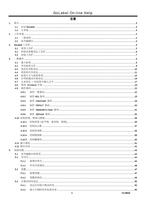
目录1. 简介 (3)1.1 启动GoLabel (3)1.2 主界面 (3)2. 工作环境 (4)2.1 一般说明 (4)2.2 命令编辑区 (4)3. GoLabel工具栏 (5)3.1 常用工具栏 (5)3.2 控制及参数设定工具栏 (6)3.3 绘制工具栏 (7)4. 一般操作 (8)4.1 建立标签 (8)4.2 开启标签文件 (9)4.3 更改打印机设定 (10)4.4 资料库打印设定 (11)4.5 标签尺寸与纸张种类 (13)4.6 打印机通讯介面设定 (16)4.7 文本设定- 在标签中输入文字 (17)4.8 使用Windows字体 (20)4.9 制作条码 (22)4.9.1 制作一维条码 (22)4.9.2 制作GS1条码 (25)4.9.3 制作MaxiCode 条码 (28)4.9.4 制作PDF417 条码 (30)4.9.5 制作DataMatrix Code 条码 (32)4.9.6 制作QRCode 条码 (34)4.10 绘制直线、框线与圆弧 (36)4.10.1 绘制直线(水平线、垂直线、斜线) (36)4.10.2 绘制实心框 (37)4.10.3 绘制直角框 (38)4.10.4 绘制圆角框 (39)4.10.5 绘制椭圆形 (40)4.11 插入图形 (41)4.12 锁住内容 (42)5. 高级功能 (43)5.1 命令编辑区的使用 (43)5.2 序列号 (44)5.2.1 新增序列号 (44)5.2.2 序列号的修改 (46)5.3 变数 (47)5.3.1 新增变数 (47)5.3.2 变数的修改 (49)5.4 日期及时间设定 (50)5.4.1 设定打印机日期及时间 (50)5.4.2 插入日期时间至标签内容 (50)5.5.1 资料库连接方式 (52)5.5.2 资料库的使用 (53)5.6 网络连接 (55)5.6.1 搜索打印机 (55)5.6.2 设定IP位址 (56)5.7 载入图形/字体/标签/DBF档/Cmd档 (57)5.7.1 载入字体 (57)5.7.2 确认载入的文件 (59)5.7.3 载入标签 (60)5.7.4 其它内容 (61)5.7.5 删除打印机内容 (61)5.7.6 同步GoLabel与打印机内容 (62)6. 条码的应用 (63)6.1 EAN 128 / GS1 Databar条码及应用识别码(AI) (63)6.1.1 关于应用识别码(Application Identifiers, AI) (63)6.1.2 AI Wizard (64)7. 其他功能说明 (66)7.1 打印机控制 (66)7.2 其他选项 (67)1.简介1.1 启动GoLabel点击Windows「开始」按钮,然后点击GoLabel,或直接点击桌面上的图标执行程序。
癌症患者生命质量量表FACT-G

癌症患者生命质量测定量表[FACT-G 中文版() ]填表说明:表内是一些与您的疾病相关的重要问题。
请在每一个问题以后圈出一个数字,以表示在过去的 7 天中最合适您的状况领域(各详细条目)一点也有一有相非不点些当常生理状况01234 GP1我精力不济01234 GP2我感觉恶心01234 GP3由于我身体不好,我知足不了家01234庭的需要GP4我感觉痛苦01234 GP5 治疗的不良反响让我感觉不舒01234服GP6我觉生病了01234 GP7我不得不卧床0234社会 / 家庭状况GS1我和朋友们很靠近01234 GS2我在感情上获得家人的支持01234 GS3我获得朋友的支持01234 GS4 我的家人已能正确视我生病这01234一事实GS5我快乐和家人讨论我的病情01234 GS6我与自己的配偶(或给我主要支01234持的人)很亲密Q1不论你近期性生活的程度,请回答下边的问题,假如你不肯意回答,请在这里注明()GS7我对自己的性生活感觉满意01234感情状况GE1我感觉伤心01234 GE2 我为自己这样对待疾病感觉自01234豪GE3我与疾病的抗争中,我愈来愈感01234到绝望GE4我感觉紧张01234 GE5我担忧可能会逝世01234 GE6我担忧自己的病情会更糟01234FACT-G()各领域计分方法(原始得分)领域条目数得分范计分方法围生理状况( PWB)70-28GP1+GP2+GP3+GP4+GP5+GP6+GP7社会|家庭状况70-28GS1+GS2+GS3+GS4+GS5+GS6+GS7( SWB)感情状况( EWB)60-24GE1+GE2+GE3+GE4+GE5+GE6功能状况( FWB)70-28GF1+GF2+GF3+GF4+GF5+GF6+GF7量表总分270-108PWB+SWB+EWB+FWB。
- 1、下载文档前请自行甄别文档内容的完整性,平台不提供额外的编辑、内容补充、找答案等附加服务。
- 2、"仅部分预览"的文档,不可在线预览部分如存在完整性等问题,可反馈申请退款(可完整预览的文档不适用该条件!)。
- 3、如文档侵犯您的权益,请联系客服反馈,我们会尽快为您处理(人工客服工作时间:9:00-18:30)。
C/W
o
TJ, TSTG
C
NOTES: 1. Measured at 1.0 MHz and applied reverse voltage of 4.0 volts 2. P.C.B. mounted on 0.2 x 0.2" (5.0 x 5.0mm) copper pad areas
元器件交易网
RS
GS1A THRU GS1M
30
AVERAGE FORWARD CURRENT (AMPS)
P.C.B. MOUNTED ON 0.2 x 0.2" (5.0 x 5.0mm) COPPER PAD AREAS 1.0
PEAK FORWARD SURGE CURRENT (AMPS)
1.5
25
8.3 MS SINGLE HALF SINE-WAVE JEDEC METHOD
B C A
D
J H G E
SMA / DO-214AC Dim Min Max A 2.29 2.92 B 4.00 4.60 1.25 1.65 C 0.152 0.305 D 4.80 5.59 E 0.051 0.203 G 0.76 1.52 H 2.00 2.62 J All Dimensions in mm
MECHANICAL DATA
Case: JEDEC DO-214AC molded plastic Terminals: Solder plated, solderable per MIL-STD-202, method 208 Polarity: Color band denotes cathode end Standard Package: 12mm tape (EIA STD EIA-481) Weight: 0.002 ounce, 0.064 gram
0
1
10
100
NUMBER OF CYCLES AT 60Hz
Figure 2. Maximum Non-Repetitive Peak Forward Surge Current
INSTANTANEOUS FORWARD CURRENT (AMPS)
100 100 TJ = 25OC f = 1.0MHz Vsig = 50mVp-p
元器件交易网
RS
GS1A THRU GS1M
SURFACE MOUNT STANDARD RECOVERY RECTIFIER VOLTAGE - 50 TO 1000 VOLTS CURRENT - 1.0 AMPERE
FEATURES
For surface mount applications Glass passivated junction Low profile package Built-in strain relief Easy pick and place Low forward voltage drop Plastic package has Underwriters Laboratory Flammability Classification 94V-0 High temperature soldering: 250oC/10 seconds at terminals
TJ = 25 OC 0.01
1 0.01 0.1 1.0 10 100 0.001
HEATING TIME (SEC)
0
20
40
60
80
100
Figure 5.Transient Thermal Impedance
PERCENT OF PEAK REVERSE VOLT AGE(%)
Figure 6.Typical Reverse Characteristics
JA JL
SYMBOL GS1A GS1B GS1D GS1G GS1J GS1K GS1M UNITS 50 100 200 400 600 VRRM 800 1000 Volts 35 70 140 280 420 VRMS 560 700 Volts 50 100 200 400 600 800 1000 Volts VDC I(AV) 1.0 Amps
20
0.5
SINGLE PHASE HALF WAVE 60Hz RESISTIVE OR INDUCTIVE LOAD
15
0 0 25 50 75 100 125
O
10
150
175
LEAD Typical Forward Current Derating Curve
MAXIMUM RATINGS AND ELECTRICAL CHARACTERISTICS
Ratings at 25oC ambient temperature unless otherwise specified Single phase half wave 60 Hz, resistive or inductive load For capacitive load, derate current by 20%
TJ = 125 OC 1
1000
THERMAL IMPEDANCE (OC / W)
TJ = 100 OC 0.1
100
10
UNITS MOUNTED ON 0.2x0.2" (5.0x5.0mm) x 0.5mil. INCHES (0.013mm) THICK COPPER LAND AREAS
Maximum Repetitive Peak Reverse Voltage Maximum RMS Voltage Maximum DC Blocking Voltage Maximum Average Forward Rectified Current at TL = 100oC Peak Forward Surge Current 8.3ms single half sine-wave superimposed on rated load (JEDEC Method) Maximum Instantaneous Forward Voltage at 1.0A Maximum DC Reverse Current at Rated DC Blocking Voltage TA = 25oC TA = 125oC IR CJ R R
10
JUNCTION CAPACITANCE (pF)
1
TJ = 25OC PULSE WIDTH = 300 1% DUTY CYCLE
10
S
0.1
1 0.01 0.01 0.4 0.6 0.8 1.0 1.2 1.4 1.6 1.8 2.0 0.1 1.0 10 100
REVERSE VOLTAGE (VOLTS)
IFSM VF
30 1.1 5 50 12 75 30 -55 to +150
Amps Volts A pF
o
Typical Junction Capacitance (NOTE 1) Maximum Thermal Resistance (NOTE 2) Operating and Storage Temperature Range
INSTANTANEOUS FORWARD VOLT AGE (VOLTS)
Figure 4.Typical Junction Capacitance
Figure 3. Typical Instantaneous Forward Characteristics
10
INSTANTANEOUS REVERSE CURRENT A)
