HADCO_LM79_LM80_Information_Brief
Q.763 - Formats and codes of the ISDN User Part of Signalling System No. 7

The format of and the codes used in the service information octet are described in 14.2/Q.704. The service indicator for the ISDN User Part is coded 0101.
Recommendation Q.763 (03/93)
1
1.2 Circuit identification code The format of the circuit identification code (CIC) is shown in Figure 2.
8
7
6
5
4
3
2
1
Circuit identification code (least significant bits)
INTERNATIONAL TELECOMMUNICATION UNION
ITU-T
TELECOMMUNICATION STANDARDIZATION SECTOR OF ITU
Q.763
(03/93)
SPECIFICATIONS OF SIGNALLING SYSTEM No. 7
Ovation I O Reference Manual

This publication adds the Eight Channel RTD module to the Ovation I/O Reference Manual. It should be placed between Sections 19 and 20.Date: 04/03IPU No.243Ovation ® Interim Publication UpdatePUBLICATION TITLEOvation I/O Reference ManualPublication No. R3-1150Revision 3, March 2003Section 19A. Eight Channel RTDModule19A-1. DescriptionThe Eight (8) channel RTD module is used to convert inputs from Resistance Temperature Detectors (RTDs) to digital data. The digitized data is transmitted to the Controller.19A-2. Module Groups19A-2.1. Electronics ModulesThere is one Electronics module group for the 8 channel RTD Module:n5X00119G01 converts inputs for all ranges and is compatible only with Personality module 5X00121G01 (not applicable for CE Mark certified systems).19A-2.2. Personality ModulesThere is one Personality module groups for the 8 channel RTD Module:n5X00121G01 converts inputs for all ranges and is compatible only with Electronics module 5x00119G01 (not applicable for CE Mark certified systems).19A-2.3. Module Block Diagram and Field Connection WiringDiagramThe Ovation 8 Channel RTD module consists of two modules an electronics module contains a logic printed circuit board (LIA) and a printed circuit board (FTD). The electronics module is used in conjunction with a personalty module, which contains a single printed circuit board (PTD). The block diagram for the 8 channel RTD moduleis shown in Figure 19A-1.Table 19A-1. 8 Channel RTD Module Subsystem ChannelsElectronic Module Personality Module85X00119G015X00121G01Figure 19A-1. 8 Channel RTD Module Block Diagram and Field Connection Wiring Diagram19A-3. SpecificationsElectronics Module (5X00119)Personality Module (5X00121)Table 19A-2. 8 Channel RTD Module SpecificationsDescription ValueNumber of channels8Sampling rate50 HZ mode: 16.67/sec. normally. In 3 wire mode, leadresistance measurement occurs once every 6.45 sec.during which the rate drops to 3/sec.60 HZ mode: 20/sec. normally. In 3 wire mode, leadresistance measurement occurs once every 6.45 sec.during which the rate drops to 2/sec.Self Calibration Mode: Occurs on demand only. The ratedrops to 1/sec. once during each self calibration cycle.RTD ranges Refer to Table 19A-3.Resolution12 bitsGuaranteed accuracy (@25°C)0.10% ±[0.045 (Rcold/Rspan)]% ± [((Rcold + Rspan)/4096 OHM)]% ± [0.5 OHM/Rspan]% ±10 m V ± 1/2LSBwhere:Rcold and Rspan are in Ohms.Temperature coefficient 10ppm/°CDielectric isolation:Channel to channel Channel to logic 200V AC/DC 1000 V AC/DCInput impedance100 M OHM50 K OHM in power downModule power 3.6 W typical; 4.2 W maximumOperating temperature range0 to 60°C (32°F to 140°F)Storage temperature range-40°C to 85°C (-40°F to 185°F)Humidity (non-condensing)0 to 95%Self Calibration On Demand by Ovation ControllerCommon Mode Rejection120 dB @ DC and nominal power line frequency+/- 1/2%Normal Mode Rejection100 dB @ DC and nominal power line frequency+/- 1/2%Table 19A-3. 8 Channel RTD RangesScale #(HEX)Wires Type Tempo FTempo CRcold(ohm)Rhot(ohm)Excitationcurrent(ma)Accuracy± ±countsAccuracy± ±% ofSPAN1310OhmPL0 to1200–18 t o6496106.3 1.090.222310OhmCU 0 to302–18 t o1508.516.5 1.0 130.32D350OhmCU 32 to2840 to1405080 1.0110.2711350OhmCU 32 to2300 to1105378 1.0120.30193100Ohm PL –4 to334–16 t o16892163.671.0110.27223100Ohm PL 32 to5200 to269100200 1.0100.25233100Ohm PL 32 to10400 to561100301 1.0100.25253120Ohm NI –12 t o464–11 t o240109360 1.0100.25263120Ohm NI 32 to1500 to70120170 1.0130.32283120Ohm NI 32 to2780 to122120225 1.0110.27804100Ohm PL 32 to5440 to290100 208 1.0100.25814100Ohm PL 356 t o446180 t o230168 186 1.0300.74824200Ohm PL 32 to6980 to370200 473 1.0120.30834200Ohm PL 514 t o648268 t o342402452 1.0290.71844100Ohm PL 32 to1240 to51100120 1.0190.47854100Ohm PL 32 to2170 to103100 140 1.0130.3286 4100Ohm PL 32 to4120 to211100 180 1.0110.27874100Ohm PL 32 to7140 to379100 240 1.0100.25884120Ohm PL 511 t o662266 t o350200230 1.0240.5919A-4. 8 Channel RTD Terminal Block Wiring Information19A-4.1. Systems Using Personality Module 5X00121G01 Each Personality module has a simplified wiring diagram label on its side, which appears above the terminal block. This diagram indicates how the wiring from the field is to beconnected to the terminal block in the base unit. The following table lists and defines the abbreviations used in this diagram.Table 19A-4. Abbreviations Used in the DiagramAbbreviation Definition+IN, -IN Positive and negative sense input connectionEarth ground terminal. Used for landing shields when the shield is to begrounded at the module.PS+, PS-Auxiliary power supply terminals.RTN Return for current source connection.SH Shield connector. used for landing shields when the shield is to begrounded at the RTD.SRC Current source connection.Note:PS+ and PS- are not used by this module.19A-5. 8 Channel RTD Module Address Locations19A-5.1. Configuration and Status RegisterWord address 13 (D in Hex) is used for both module configuration and module status. The Module Status Register has both status and diagnostic information. The bit information contained within these words is shown in Table 19A-5.Definitions for the Configuration/Module Status Register bits:Bit 0:This bit configures the module (write) or indicates the configuration state of the module (read). A “1” indicates that the module is configured. Note that until the module is configured, reading from addresses #0 through #11 (B in Hex) will produce an attention status.Bit 1:This bit (write “1”) forces the module into the error state, resulting in the error LED being lit. The read of bit “1” indicates that there is an internal module error,or the controller has forced the module into the error state. The state of this bit is always reflected by the module’s Internal Error LED. Whenever this bit is set,an attention status is returned to the controller when address #0 through #11(B in Hex) are read.Table 19A-5. 8 Channel RTD Configuration/Status Register (Address 13 0xD in Hex)Bit Data Description -Configuration Register (Write)Data Description -Status Register (Read)0Configure Module Module Configured(1 = configured; 0 = unconfigured)1Force errorInternal or forced error(1 = forced error; 0 = no forced error)250/60 Hz select (0 = 60Hz, 1 = 50Hz)50/60 Hz System (1 = 50Hz) d(read back)3SELF_CAL (Initiates Self Calibration)Warming bit (set during power up or configuration)40050060Module Not Calibrated 708CH.1 _ 3/4 Wire.CH.1 _ 3/4 Wire - Configuration (read back)9CH.2 _ 3/4 Wire.CH.2 _ 3/4 Wire - Configuration (read back)10CH.3 _ 3/4 Wire.CH.3 _ 3/4 Wire - Configuration (read back)11CH.4 _ 3/4 Wire.CH.4 _ 3/4 Wire - Configuration (read back)12CH.5 _ 3/4 Wire.CH.5 _ 3/4 Wire - Configuration (read back)13CH.6 _ 3/4 Wire.CH.6 _ 3/4 Wire - Configuration (read back)14CH.7 _ 3/4 Wire.CH.7 _ 3/4 Wire - Configuration (read back)15CH.8 _ 3/4 Wire.CH.8 _ 3/4 Wire - Configuration (read back)Bit 2:The status of this bit (read) indicates the conversion rate of the module, write to this bit configures the conversion rate of A/D converters as shown below.see Table 19A-6.Bit3:Write: This bit is used to initiate self-calibration. Read: This bit indicates that the module is in the “Warming” state. this state exists after power up and ter-minates after 8.16 seconds. the module will be in the error condition during the warm up period.Bit4 & 5:These bits are not used and read as “0” under normal operation.Bit 6:This bit (read) is the result of a checksum test of the EEPROM. A failure of this test can indicate a bad EEPROM, but it typically indicates that the module has not been calibrated. A “0” indicates that there is no error condition. If an error is present, the internal error LED is lit and attention status will be returned for all address offsets 0-11 (0x0 - 0xB). The “1” state of this bit indicates an unre-coverable error condition in the field.Bit 7:This bits is not used and read as “0” under normal operation.Bit 8 - 15:These bits are used to configure channels 1 - 8 respectively for 3 or 4 wire op-eration. A “0” indicates 3 wire and a “1” indicates 4 wire operation, see Table 19A-7 and Table 19A-8).Word address 12 (0xC) is used to configure the appropriate scales for Channels 1 - 4 (refer to Table 19A-7 and Table 19A-8).Table 19A-6. Conversion Rate Conversion Rate (1/sec.)Bit 260 (for 60Hz systems)050 (for 50Hz systems)1Table 19A-7. Data Format for the Channel Scale Configuration Register(0xC)Bit Data Description Configuration (Write)Data Description Status (Read)0 Configure Channel #1scale - Bit 0Channel #1 scale configuration (read back) - Bit 01Configure Channel #1scale - Bit 1Channel #1 scale configuration (read back) - Bit 12Configure Channel #1scale - Bit 2Channel #1 scale configuration (read back) - Bit 23Configure Channel #1scale - Bit 3Channel #1 scale configuration (read back) - Bit 34Configure Channel #2 scale - Bit 0Channel #2 scale configuration (read back) - Bit 05Configure Channel #2 scale - Bit 1Channel #2 scale configuration (read back) - Bit 16Configure Channel #2 scale - Bit 2Channel #2 scale configuration (read back) - Bit 27Configure Channel #2 scale - Bit 3Channel #2 scale configuration (read back) - Bit 38Configure Channel #3 scale - Bit 0Channel #3 scale configuration (read back) - Bit 09Configure Channel #3 scale - Bit 1Channel #3 scale configuration (read back) - Bit 1Caution:Configuring any or all channel scales while the system is running will cause all channels to return attention status for up to two seconds following the reconfiguration.Caution:Configuring any or all channel scales while the system is running will cause all channels to return attention status for up to two seconds following the reconfiguration.10Configure Channel #3 scale - Bit 2Channel #3 scale configuration (read back) - Bit 211Configure Channel #3 scale - Bit 3Channel #3 scale configuration (read back) - Bit 312Configure Channel #4 scale - Bit 0Channel #4 scale configuration (read back) - Bit 013Configure Channel #4 scale - Bit 1Channel #4 scale configuration (read back) - Bit 114Configure Channel #4 scale - Bit 2Channel #4 scale configuration (read back) - Bit 215Configure Channel #4 scale - Bit 3Channel #4 scale configuration (read back) - Bit 3Table 19A-8. Data Format for the Channel Scale Configuration Register(0xE)Bit Data Description Configuration (Write)Data Description Status (Read)0 Configure Channel #5 scale - Bit 0Channel #5 scale configuration (read back) - Bit 01Configure Channel #5 scale - Bit 1Channel #5 scale configuration (read back) - Bit 12Configure Channel #5 scale - Bit 2Channel #5 scale configuration (read back) - Bit 23Configure Channel #5 scale - Bit 3Channel #5 scale configuration (read back) - Bit 34Configure Channel #6 scale - Bit 0Channel #6 scale configuration (read back) - Bit 05Configure Channel #6 scale - Bit 1Channel #6 scale configuration (read back) - Bit 16Configure Channel #6 scale - Bit 2Channel #6 scale configuration (read back) - Bit 27Configure Channel #6 scale - Bit 3Channel #6 scale configuration (read back) - Bit 38Configure Channel #7 scale - Bit 0Channel #7 scale configuration (read back) - Bit 09Configure Channel #7 scale - Bit 1Channel #7 scale configuration (read back) - Bit 110Configure Channel #7 scale - Bit 2Channel #7 scale configuration (read back) - Bit 211Configure Channel #7 scale - Bit 3Channel #7 scale configuration (read back) - Bit 312Configure Channel #8 scale - Bit 0Channel #8 scale configuration (read back) - Bit 013Configure Channel #8 scale - Bit 1Channel #8 scale configuration (read back) - Bit 114Configure Channel #8 scale - Bit 2Channel #8 scale configuration (read back) - Bit 215Configure Channel #8 scale - Bit 3Channel #8 scale configuration (read back) - Bit 3Table 19A-7. Data Format for the Channel Scale Configuration Register(0xC)19A-6. Diagnostic LEDsTable 19A-9. 8 Channel RTD Diagnostic LEDsLED DescriptionP (Green)Power OK LED. Lit when the +5V power is OK.C (Green)Communications OK LED. Lit when the Controller is communicatingwith the module.I (Red)Internal Fault LED. Lit whenever there is any type of error with themodule except to a loss of power. Possible causes are:n - Module initialization is in progress.n - I/O Bus time-out has occurred.n - Register, static RAM, or FLASH checksum error.n - Module resetn - Module is uncalibrated.n - Forced error has been received from the Controllern - Communication between the Field and Logic boards failedCH1 - CH 8 (Red)Channel error. Lit whenever there is an error associated with a channel or channels. Possible causes are:n - Positive overrangen - Negative overrangen Communication with the channel has failed。
000pov supply chain visibility xx

What Do Users Want from B2B Connectivity?
According to AMR’s interview of 152 executives on their views of the relative importance on the marketplace functionalities, SC Visibility and logistics-related functions (Order Status/Tracking and Transportation management) were among the highest in importance.
Final Draft
Digital Markets and Supply Chain
Supply Chain Visibility and Logistics Collaboration
Point of View
David A. Hance, Northeast Region, Stamford, CT Naoji Takeda, Northeast Region, New York, NY M. Christopher Herrera, Northeast Region, New York, NY John Scott, Northeast Region, Roseland, NJ April 2001
中国浙江刺齿虫兆属一新种_弹尾纲_长角虫兆科_英文_
A New Species of the Genus Homidia(Collembola: Entomobryidae) fromZhejiang Province, ChinaPAN Zhi-xiang1, SHI Shi-di1, ZHANG Feng2①(1. School of Life Sciences, Taizhou University, Linhai, Zhejiang 317000, China;2. School of Life Sciences, Nanjing University, Nanjing, Jiangsu 210093, China)Abstract:A new species, Homidia unichaeta, sp. nov. from East China is described. It ischaracterized by colour pattern, only one posterior macrochaeta on Abd. IV, labial setae Eand L1 smooth, seta pi spiny and slightly thinner and about 1.5 times as long as bs1 and bs2.The three similar species of Homidia are compared.Key words: Collembola; Entomobryidae; Homidia; chaetotaxy; taxonomy; new species;ChinaCLC number: Q969.14 Document code: AArticle ID: 1000-7482(2010)04-0241-07The genus Homidia was established by Börner (1906) as a subgenus of Entomobrya Rondani for Entomobrya (Homidia) cingula Börner, 1906. Denis (1929) raised it to the generic level. The genus is characterized by presence of spines on inner edges of dentes in adults, “eyebrow” macrochaetae present on anterior part of Abd. IV, ommatidia 8+8,bilobed Ant. IV apical bulb, bidentate mucro with subapical tooth larger than the apical one, mucronal basal spine short with tip reaching subapical tooth, and absence of body scales. So far, 47 species of the genus have been described in the world, 25 of them recorded from China; only 3 of them (H. polyseta Chen & Lin, 1998; H. latifolia Chen & Li, 1999; H. linhaiensis Shi, Pan & Qi, 2009) were described from Zhejiang Province, China. A new species, H. unichaeta sp. nov., also from Zhejiang Province, is described here.Method:Specimens were cleared in lactic acid, mounted under a coverslip in Marc André II solution, and observed using Leica DM2500 and Nikon 80i microscopes. The photograph was taken with Leica AL2 and Nikon SM1000 microscopes using a mounted Nikon DS-Fi1 camera and enhanced with Photoshop 7.0 (Adobe Inc.). All length data was measured with NIS-Elements Documentation (Nikon). Cephalic dorsal chaetotaxy is after Szeptycki’s system (1973),interocular setae after Mari-Mutt (1979, 1986), setae of labial palp after Fjellberg Received date: 2010-09-05Foundation items: The project was supported by The Qingnian Foundation of Taizhou University (2010QN17) and Zhejiang Provincial Natural Science Foundation of China (Y3100278)①Corresponding author, E-mail: xtmtd.zf@241242 昆虫分类学报第32卷第4期(1998), labial setae after Gisin (1964), dorsal chaetotaxy after Szeptycki (1979). Abbreviations: Th. -thoracic segment; Abd. -abdominal segment; Ant. -antennal segment; ms -microsensillum/a; s -sensillum/a; mac -macrochaeta (e); mic -microchaeta (e).Homidia unichaeta,sp. nov. (Figs. 1~22)Size. Maximum body length 1.72 mm.Colour pattern. Ground colour pale to yellowish in alcohol, eye patches dark, antennae violet and gradually darker towards tip, legs and lateral of body slightly pigmented (Fig. 1~2).Figs. 1~2 Homidia unichaeta,sp. nov. 1-2. habitus (lateral views, showing different density of pigment) Head. Ommatidia 8+8, G and H smaller than others, and always difficult to see, interocular setae as p, r, t (Fig. 3), seta p is the longest one among them. Antenna 1.48-2.49 times as long as cephalic diagonal, shorter than body length, antennal segment ratio as I∶II∶III∶IV=1∶1.37-2.02∶1.57-1.99∶2.12-3.94. Basal Ant. I with 2-4 dorsal and 3-5 ventral spiny setae (Fig. 4). Ant. II distally with 2-3 rod-like sensilla (1-2 longer, 1 shorter) (Fig. 5). Ant. III organ with 2 rod-like sensilla and other 3 small sensilla (Fig. 6). Ant. IV apical bulb bilobed (Fig. 7). Dorsal cephalic chaetotaxy with 3 antennal (A), 3 ocellar (O) and 5 sutural (S) mac (Fig. 3). Prelabral and labral setae as 4/5, 5, 4, all smooth. Labral papillae absent. Labral intrusion deeply V-shaped. Maxillary outer lobe with 1 apical seta, 1 subapical seta and 3 sublobal hairs on sublobal plate, subapical seta subequal to apical one. Five labial papillae A-E respectively with 0, 5, 0, 4, 4 guard setae, lateral process (l. p.) differentiated with tip not beyond apex of the papilla E (Fig. 9). Proximal with 5 smooth setae. Setal formula of labial base as MREL1L2, setae E and L1 smooth and others ciliate (Fig. 8).Thorax. Complete ms as 10/10100. Th. II with 3 (4) medio-medial setae (m1, m2, m2i; m2i2 rarely present), 3medio-sublateral setae (m4, m4i and m4p), 2 s and 1ms (ms internal to s); posterior with about 25 mac, p6 as mic (Fig. 10). Th. III with about 37 mac and 2 s, m5p as mesochaeta or mac, seta p1i2 rarely present and p4 as mic (Fig. 11). Coxal macrochaetal formula as 3/4+1, 3/4+2 (Fig. 12). Trochanteral organ with 20-32 (5-6 in posterior and 3–4 in ventral arm) smooth spines (Fig. 13). Inner differentiated tibiotarsal setae slightly ciliate, most distal smooth seta present on hind leg slightly shorter than tenent hair in length.Tenent hair clavate and subequal to inner edge of unguis. Unguis with 3 inner, 2 lateral minute teeth. Unguiculus lanceolate with outer edge smooth (Fig. 14).Abdomen. Abd. I with 9 (10) (a2-3, m2-4, m2i, m4i, m4p, a5; a1 rarely present; m4i always smaller than m4p) mac and 1 s and 1ms (ms anterior to s). Abd. II with 6 (a2, a3, m3, m3e, m3ea, m3ep; a3 rarely as mic) central, 1 (m5) lateral mac and 2 s. Abd. III with 2 (a2 and m3) central, 4 (am6, pm6, m7a, p6) lateral, mac, and 2 s and 1ms (Fig. 15). Abd. IV with 3-82010年12月潘志祥等:中国浙江刺齿虫兆属一新种 243 (always as 5-7) mac on anterior part arranged in irregular transverse row, and 1 unclear homology mac on posterior part (Fig. 17). Abd. V with 3 s (Fig.16). Anterior face of ventral tube (VT) with many ciliate setae, including 3+3 mac, line connecting proximal (Pr) and external-distal (Ed) (following Chen & Li, 1997) mac subparallel to median furrow (Fig. 19); posterior with 5-7 (always as 5) smooth and numerous ciliate setae; lateral flap with 6 smooth (rarely as 7) and 10-14 ciliate setae (Fig. 18). Manubrial plaque with 3 pseudopores, 2 inner and 4-7 outer ciliate setae (Fig. 20). Dentes with 19-23 spines; basal setae (following Szeptycki 1973) (bs1 and bs2) spiny, bs1 shorter than bs2; proximal-inner seta (pi) spiny, slightly thinner and about 1.5 times as long as bs1 and bs2 (Fig.21). Mucro bidentate with subapical tooth obviously larger than apical one; basal spine short, with tip only reaching apex of subapical tooth (Fig. 22). Tenaculum with 4+4 teeth and 1 large, multi-laterally ciliate basal seta. Male genital plate papillate.Figs. 3~10 H. unichaeta,sp. nov.3. dorsal cephalic chaetotaxy (right side);4. basal Ant. I;5. distal Ant. II;6. Ant. III organ;7. distal Ant. IV;8. labial base (left side);9. labial papilla E; 10. dorsal chaetotaxy of Th. II (right side)244 昆虫分类学报第32卷第4期Figs. 11~16 H. unichaeta, sp. nov.11. dorsal chaetotaxy of Th. III (right side); 12. coxal macrochaetal formula (A. fore leg; B. mid leg; C. hind leg);13. trochanteral organ; 14. claw on hind leg; 15. dorsal chaetotaxy of Abd. I-III (right side); 16. dorsal chaetotaxy of Abd. V (right side)Ecology:under the leaf litter of Cinnamomum camphora(Linn.) and Castanea mollissima Blume mixed forest.Holotype: ♂, on slide, collect number S1007, collected by PAN Zhi-xiang, from Sanfeng Temple, Linhai City, Zhejiang Province, China, 8-X-2005; Paratypes: 1♂, 10♀♀ and 1 larva on slide, 6 specimens in alcohol, collection information same as holotype. Three paratypes (2♀♀ on slide and 1 in alcohol) deposited in School of Life Sciences, Nanjing University, other type materials deposited in School of Life Sciences, Taizhou University.Etymology: named after the Latin words “uni+chaeta” (the only mac on posterior Abd. IV).Remark: The new species is characterized by weak pigment on dorsal terga; only one mac on posterior Abd. IV, labial setae E and L1 smooth, seta pi on basal dentes spiny and longer than bs1 and bs2.2010年12月 潘志祥等:中国浙江刺齿虫兆属一新种 245Figs. 17~22 H. unichaeta , sp. nov.17. dorsal chaetotaxy of Abd. IV (right side); 18. posterior face and lateral flap of ventral tube; 19. anterior face of ventral tube; 20. manubrial plaque; 21. basal dente; 22. distal dentes and mucroThe new species is most similar to Homidia haikea Christiansen & Bellinger, 1992 in colour pattern, dorsal cephalic chaetotaxy, labial setae, maxillary out lobe, Abd. II chaetotaxy, male genital plate; however, it can be easily distinguished from the latter by chaetotaxy of Th. II-Abd. I and Abd. IV-Abd. V, labral papillae, coxal macrochaetal formula, seta pi on basal dentes and dental spines. It is also similar to Homidia heugsanica Lee & Park, 1984 in head chaetotaxy, Th. II-Abd. II chaetotaxy, smooth setae on posterior face and lateral flap of ventral tube, mac on anterior face of ventral tube, coxal macrochaetal famula and structure of claw; however, it differs from H. heugsanica by colour pattern, labral papillae, labial basal chaetotaxy, mac on posterior Abd. IV, seta pi on basal dentes. The main differences of these similar species of Homidiaare listed in Table 1.246 昆虫分类学报第32卷第4期Table 1. Main differences among the new species and the 2 related species of HomidiaCharacters H. unichaeta,sp. nov. H. haikea Christiansen &Bellinger, 1992 H. heugsanica Lee &Park, 1984Maximum body length (mm) 1.72 3.5 1.5Dark patch on Abd. V-VI absent absent presentLabral papillae absent broad 4 minuteSeta L1 on labial base smooth smooth ciliateMac on Abd. I 9-10 (always as 9)11 8 Seta a2 on Abd. III mac - micMac on posterior Abd. IV 1 5 2Mac on eyebrow 3-8 7-9 (10) 4-6Teeth on inner margin of claw 3 4 3The line link Pr with Ed on anteriorVT to median furrowsubparallel parallel oblique Smooth setae on posterior VT 5-7 (always as 5) - 4Spiny setae on trochanteral organ 20-32 - 15-22Seta pi on basal dentes spiny slender slenderNumber of dental spines 14-23 38-46 (51) 19-23Distribution China(ZhejiangProvince)USA (Hawaii) Korea-: the characters unclearAcknowledgement: Thanks to Prof. CHEN Jian-xiu (Nanjing University, China) for his useful assistance.REFERENCES[1] Börner C. Das system der Collembolen nebst Beschreibung neuer Collembolen des Hamburger Naturhistorischen Museums[J].Mitteilungen aus den Naturhistorischen Museum in Hamburg, 1906, 23: 147-188.[2] Chen J X., Lin R. A new species of the Homidia (Collembola: Entomobryidae) from Zhejiang Province, China[J].Entomotaxonomia, 1998, 20(1): 21-24.[3] Chen J X, Li L R. A new species of the genus Homidia (Collembola: Entomobryidae) from Jiangxi Province of China[J].Entomotaxonomia, 1997, 19(2): 79-82.[4] Chen J X, Li L R. A new species of the genus Homidia (Collembola: Entomobryidae) from China[J]. Entomologia Sinica, 1999,6(1): 25-28.[5]Christiansen K, Bellinger P. Insects of Hawaii: V ol. 15. Collembola[M]. Honolulu, Hawaii: University of Hawaii Press, 1992,1-445.[6] Denis J R. Notes sur les Collemboles recoltes dans ses voyages par le Prof. F. Silvestri (I). Collemboles D’Extreme-Orient[J].Bollettino del Laboratorio di zoologia generale e agraria della Facoltà agraria in Portici, 1929, 22: 166-171.[7] Fjellberg A. The labial palp in Collembola[J]. Zoologischer Anzeiger, 1998, 237: 309-330.[8] Gisin H. European Collembola. VII[J]. Revue Suisse de Zoologie, 1964, 71: 649-678.[9] Lee B H, Lee W K. A Taxonomic Study of Soil Microarthropods with Reference to Homidia (Collembola) and Oribater(Acari)[J]. Annual Report of Biological Research, 1981, 2: 128-140.[10] Lee B H, Park K H. Some Entomobryidae Including Six New Species and One New Record of Cave Form (Collembola) fromKorea[J]. Korea Journal of Zoology, 1984, 27(3): 177-188.[11] Mari-Mutt J A. A revision of the genus Dicranocentrus Schött (Insecta: Collembola: Entomobryidae)[J]. College AgriculturalSciences Agricultural Experiment Station, University of Puerto Rico, Bulletin, 1979, 259: 1-79.2010年12月潘志祥等:中国浙江刺齿虫兆属一新种 247[12] Mari-Mutt J A. Puerto Rican species of Lepidocyrtus and Pseudosinella (Collembola: Entomobryidae)[J]. Caribbbean Journalof Sciences, 1986, 22: 1-48.[13] Shi S D, Pan Z X, Bai Y. A new species of the genus Homidia (Collembola: Entomobryidae) from west China[J].Entomotaxonomia, 2009, 31(4): 241-246.[14] Shi S D, Pan Z X, Qi X. A new species of the genus Homidia Börner, 1906 (Collembola: Entomobryidae) from East China[J].Zootaxa, 2009, 2020: 63-68.[15] Szeptycki A. North Korean Collembola. I. The genus Homidia Börner, 1906 (Entomobryidae)[J]. Acta Zoologica Cracoviensia,1973, 31: 23-39.[16] Szeptycki A. Morpho-systematic studies on Collembola. IV. Chaetotaxy of the Entomobryidae and its phylogeneticalsignificance[M]. Kraków: Polska Akademia Nauk, 1979, 1-219.中国浙江刺齿虫兆属一新种(弹尾纲:长角虫兆科)潘志祥1,施时迪1,张 峰2(1. 台州学院生命科学学院,浙江临海 317000;2. 南京大学生命科学学院,江苏南京 210093)记述中国东部刺齿虫兆属1新种,Homidia unichaeta, sp. nov.,此新种的鉴别特征有体色,第IV腹节后部的仅1根大毛,下唇基部的光滑毛E和L1,弹器齿节基部的刺状毛pi。
管状氧化锌

Cite this: J. Mater. Chem. A, 2013, 1, 814
Porous ZnO microtubes with excellent cholesterol sensing and catalytic properties†
Arnab Kanti Giri, Apurba Sinhamahapatra, S. Prakash, Jayesh Chaudhari, Vinod Kumar Shahi* and Asit Baran Panda‡*
Received 29th August 2012 Accepted 19th October 2012 DOI: 10.1039/c2ta00107a /MaterialsA
Introduction
The development of novel nanostructured metal oxides with varying sizes and shapes has stimulated remarkable research interest in recent frontier research of their novel size- and shape-dependent properties and tailorable functionalities.1 Particularly, porous structures with varying morphologies are in the spot light due to their ir high porosity; they exhibit unique physicochemical properties compared to their non-porous analogues, and are important materials for technological applications such as catalysis, sensing, Li-ion battery electrodes, solar cells, and so on.2
海尔达奥达西斯型号参比说明书

Towing Capacity1: 3,500 lbs••••••Comfort and ConvenienceDESCRIPTIONPower Windows with Auto-Up/Down Driver’s and Front Passenger’s WindowProgrammable Power Door and Tailgate LocksCruise ControlTilt and Telescopic Steering ColumnDriver’s and Front Passenger’s Illuminated Vanity Mirrors Map Lights (all rows)Front Bag HookLockable Glove CompartmentAmbient Console LightingBeverage Holders (all rows)Chrome Door HandlesCoin HolderPassenger-Assist Grips (front and 2nd-row)Garment Hooks (2nd and 3rd row, 4 total)Remote Fuel Filler Door ReleaseFront Door Courtesy LightsRear Window Defroster •••••••••••••••••LX•••••••••••••••••EX•••••••••••••••••SE•••••••••••••••••TOURING•••••••••••••••••EX-L•••••••••••••••••TOURING ELITEIntegrated Sunshades2nd Row3rd RowHonda DVD Rear Entertainment Systemwith High-Resolution WVGA (800x480) ScreenHonda DVD UltraWide Entertainment System with HDMI® Technology4 with High-Resolution WVGA (800x480) Screen •••••••••••••Available3Available3••••••Customizable Feature SettingsBluetooth® HandsFreeLink®5Bluetooth® Streaming Audio5Pandora®16 Compatibility6SMS Text Message Function7USB Audio Interface8MP3 / Auxiliary Input JackMP3 / Windows Media®9 Audio (WMA) Playback CapabilityRadio Data System (RDS)Integrated Glass AntennaHondaLink® Featuring Aha™10 CompatibilityAudio Touch-ScreenSiriusXM® Radio11Honda Satellite-Linked Navigation System™12Voice RecognitionFM TrafficHD Radio™13240-Watt AM / FM / CD Audio System with 7 Speakers, including Subwoofer270-Watt AM / FM / CD Audio System with 7 Speakers, including Subwoofer •••••••••••••••••••••••••••••••••••••••••••••••••••••••••••••••••••Available3Available3Available3without Navigation•••••••••••••••••Passive SafetyDESCRIPTIONAdvanced Compatibility Engineering™ (ACE™) Body Structure Dual-Stage, Multiple-Threshold Front Airbags (SRS) SmartVent® Front Side Airbags3-Row Side Curtain Airbags with Rollover SensorDriver’s and Front Passenger’s Active Head Restraints3-Point Seat Belts at All Seating PositionsFront 3-Point Seat Belts with Automatic Tensioning System Lower Anchors and Tethers for Children (LATCH)Lower Anchors (2nd-Row All, 3rd-Row Outboard)Tether Anchors (2nd-Row All, 3rd-Row All)Driver’s and Front Passenger’s Seat-Belt ReminderChild-Proof Rear Door Locks LX••••••••••••EX••••••••••••SE••••••••••••TOURING••••••••••••EX-L••••••••••••TOURING ELITE••••••••••••Daytime Running Lights (DRL) Rearview Camera with Guidelines16 Multi-AngleForward Collision Warning (FCW)17 Lane Departure Warning (LDW)18••••••with Navigation•••••••••••••••©2016 American Honda Motor Co., Inc. All information contained herein applies to U.S. vehicles only.Please see our Privacy Policy and Legal Terms and Conditions .Requires surge-type or electric trailer brakes and available Honda accessory towing package and hitch ball. Premium unleaded fuel recommended when towing. Please see your Honda dealer for details.HomeLink® is a registered trademark of Gentex CorporationThe Honda Satellite-Linked Navigation System™ and DVD Rear Entertainment System are only available separately on EX-L models.A separate source device is required to use split-screen function. HDMI, the HDMI Logo, and High-Definition Multimedia Interface are trademarks or registered trademarks of HDMI Licensing, LLC, in the United States and other countries.The Bluetooth ® word mark and logos are owned by the Bluetooth SIG, Inc., and any use of such marks by Honda Motor Co., Ltd., is under license.Pandora, the Pandora logo, and the Pandora trade dress are trademarks or registered trademarks of Pandora Media, Inc. Used with permission. Compatible with select smartphones. See: /everywhere/mobile. Not all devices compatible with USB connection. Your wireless carrier’s rate plans apply.Compatible with select phones with Bluetooth®. Your wireless carrier’s rate plans apply. State or local laws may limit use of texting feature. Only use texting feature when conditions allow you to do so safely.The USB Audio Interface is used for direct connection to and control of some current digital audio players and other USB devices that contain MP3, WMA or AAC music files. Some USB devices with security software and digital rights-protected files may not work. Please see your Honda dealer for details.Windows Media® is a trademark or registered trademark of Microsoft Corporation in the United States and/or other countries.Compatible smartphone required. All Aha platform feeds are audible, not visual in nature. Vehicle does not provide any feeds. Some state laws prohibit the operation of handheld electronic devices while operating a vehicle. Launch smartphone applications only when the vehicle is safely parked. Aha is a trademark of Harman International Industries, Inc. Your wireless carrier’s rates may apply.SiriusXM services require a subscription after any trial period. If you decide to continue your SiriusXM service at the end of your trial subscription, the plan you choose will automatically renew and bill at then-current rates until you call SiriusXM at 1-866-635-2349 to cancel. See our Customer Agreement for complete terms at . Fees and programming subject to change. XM satellite service is available only to those at least 18 years and older in the 48 contiguous United States and D.C. ©2016 SiriusXM Radio Inc. Sirius, XM and all related marks and logos are trademarks of SiriusXM Radio Inc.The Honda Satellite-Linked Navigation System™ is available on EX-L models and standard on Touring models in the United States, Canada and Puerto Rico. (FM Traffic service only available in the United States, except Alaska). Please see your Honda dealer for details.HD Radio is a proprietary trademark of iBiquity Digital Corporation.VSA is not a substitute for safe driving. It cannot correct the vehicle’s course in every situation or compensate for reckless driving. Control of the vehicle always remains with the driver.For optimal tire wear and performance, tire pressure should be checked regularly with a gauge. Do not rely solely on the monitor system. Please see your Honda dealer for details.Always visually confirm that it is safe to drive before backing up; the rearview camera display does not provide complete information about all conditions and objects at the rear of your vehicle.FCW cannot detect all objects ahead and may not detect a given object; accuracy will vary based on weather, speed and other factors. System operation affected by extreme interior heat. FCW does not include a braking function. Driver remains responsible for safely operating vehicle and avoiding collisions.LDW only alerts drivers when lane drift is detected without a turn signal in use. LDW may not detect all lane markings or lane departures; accuracy will vary based on weather, speed and road condition. System operation affected by extreme interior heat. Driver remains responsible for safely operating vehicle and avoiding collisions.1.2.3.4.5.6.7.8.9.10.11.12.13.14.15.16.17.18.。
7370_schematics

Service SchematicsRM-70Exploded view and component disposalIMPORTANT:This document is intended for use by authorized NOKIA service centers only.Introduction“Service Schematics” was created with focus on customer care.The purpose of this document is to provide further technical repair information for NOKIA mobile phones on Level 3/4 service activities.It contains additional information such as e.g. “Component finder”,“Frequency band table” or “Antenna switch table”.The “Signal overview” page gives a good and fast overview about the most important signals and voltages on board.Saving process time and improving the repair quality is the aim of this document.It is to be used additionally to the service manual and other training or service information such as Service Bulletins.All measurements were made using following equipment:Nokia repair SW : Phoenix version 2005.20.7.98 Oscilloscope : Fluke PM 3380A/BSpectrum Analyzer : Advantest R3162 with an analog probe RF-Generator / GSM Tester : Rhode & Schwarz CMU 200Multimeter : Fluke 73 Series IIWhile every endeavour has been made to ensure the accuracy of this document, some errors may exist. If the reader finds any errors, NOKIA should be notified in writing. Please send E-Mail to: training.sace@ training.sace@Copyright © NOKIAThis material, including documentation and any related computer programs is protected by copyright, controlled by NOKIA. All rights are reserved. Copying, including reproducing, modifying, storing, adapting or translating any or all of this material requires the prior written consent of NOKIA. This material also contains companyconfidential information,which may not be disclosed to others without the prior written consent of NOKIA.7370NOKIAR2100GEN_OUT(3:0)CHARGERUSB_ACI(7:0)USB_CMT(8:0)CBUS(3:0)EMINT(1:0)PUSL(7:0)CHSWSTATSETCURR110nPCM(3:0)PUSL(7:0)AUDIO(8:0)FM_CMT(2:0)TXC_CONV(2:0)Customer Care / Service & Support Readiness / Content Creation Management Copyright © 2005 NOKIA Only for training and service purposes Version: 1.003.11.20057370 RM-70Board version: 1lua_50aPage 12(12)Component finder LCD PWB。
IP178C_1资料
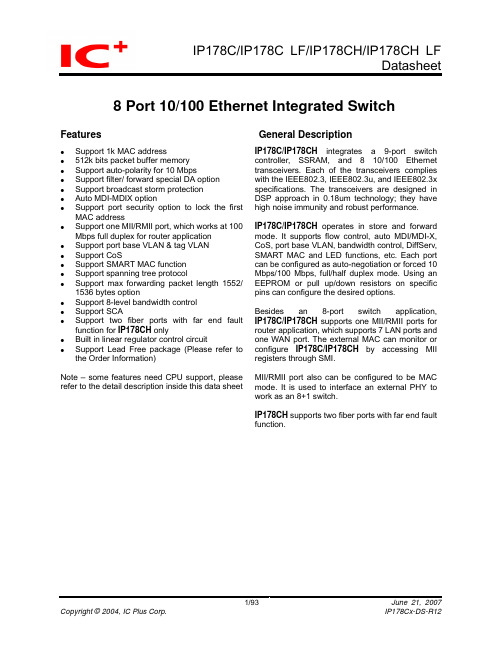
8 Port 10/100 Ethernet Integrated SwitchFeatures GeneralDescriptionSupport 1k MAC address512k bits packet buffer memorySupport auto-polarity for 10 MbpsSupport filter/ forward special DA optionSupport broadcast storm protectionAuto MDI-MDIX optionSupport port security option to lock the first MAC addressSupport one MII/RMII port, which works at 100 Mbps full duplex for router applicationSupport port base VLAN & tag VLANSupport CoSSupport SMART MAC functionSupport spanning tree protocolSupport max forwarding packet length 1552/ 1536 bytes optionSupport 8-level bandwidth controlSupport SCASupport two fiber ports with far end fault function for IP178CH onlyBuilt in linear regulator control circuitSupport Lead Free package (Please refer to the Order Information)Note – some features need CPU support, please refer to the detail description inside this data sheet IP178C/IP178CH integrates a 9-port switch controller, SSRAM, and 8 10/100 Ethernet transceivers. Each of the transceivers complies with the IEEE802.3, IEEE802.3u, and IEEE802.3x specifications. The transceivers are designed in DSP approach in 0.18um technology; they have high noise immunity and robust performance.IP178C/IP178CH operates in store and forward mode. It supports flow control, auto MDI/MDI-X, CoS, port base VLAN, bandwidth control, DiffServ, SMART MAC and LED functions, etc. Each port can be configured as auto-negotiation or forced 10 Mbps/100 Mbps, full/half duplex mode. Using an EEPROM or pull up/down resistors on specific pins can configure the desired options.Besides an 8-port switch application, IP178C/IP178CH supports one MII/RMII ports for router application, which supports 7 LAN ports and one WAN port. The external MAC can monitor or configure IP178C/IP178CH by accessing MII registers through SMI.MII/RMII port also can be configured to be MAC mode. It is used to interface an external PHY to work as an 8+1 switch.IP178CH supports two fiber ports with far end fault function.Table Of Contents Features (1)General Description (1)Table Of Contents (2)Revision History (3)Pin diagram (IP178C) (10)1Pin description (15)Pin description (continued) (16)Pin description (continued) (18)Pin description (continued) (19)Pin description (continued) (20)Pin description (continued) (21)Pin description (continued) (22)Pin description (continued) (24)Pin description (continued) (25)Pin description (continued) (26)Pin description (continued) (27)Pin description (continued) (28)2Functional Description (29)2.1Flow control (32)2.2Broadcast storm protection (33)2.3Port locking (34)2.4Port base VLAN (35)2.5Tag VLAN/ Tag and un-tag function (36)2.6Tag VLAN (36)2.7Tag VLAN in router application (37)2.8Smart MAC (38)2.9CoS (42)2.9.1Port base priority (42)2.9.2Frame base priority (42)2.10Spanning tree (44)2.11Static MAC address table (46)2.12Serial management interface (47)2.13SCA (48)2.14Bandwidth control (48)2.15Register descriptions (49)3Electrical Characteristics (86)3.1Absolute Maximum Rating (86)3.2DC Characteristic (86)3.3AC Timing (87)3.3.1PHY Mode MII Timing (87)3.3.2MAC Mode MII Timing (88)3.3.3RMII Timing (89)3.3.4SMI Timing (90)3.3.5EEPROM Timing (91)3.4Thermal Data (91)4Order information (92)5Package Detail (93)Revision HistoryRevision # Change Descriptionrelease.IP178C-DS-R01 InitialIP178C-DS-R02 1. Modify Pin diagram in page 9, pin_89 from HASH_MODE[1]/LINK_LED7 to MLT3_DET/LINK_LED7,pin 84 from LOW_10M_DIS to SCA_DIS, pin_36 fromSCA to NC, VCTRL to REG_OUT2. Replace VCTRL with REG_OUT3. Modify HASH_MODE [1] to MLT3_DET in page 17, 54 & 554. Modify pin 84 from LOW_10M_DIS to SCA_DIS, pin_36 from SCA to NC5. Change BF_STM_THR_SEL [1:0] from 01: 128 frames to 126 frames in page 746. Modify EXT MII Pin description in page 21, 22, 237. "100M" change to "100 Mbps" and "10M" change to "10 Mbps".8. Modify PHY mode for only support one MIICLK on page 259. Add in Thermal Data on page 8510. Add in power consumption on page 8011. P.54 PHY30.1[12] Default value=0, P.56 PHY30.2[7] Default value=0, P.56PHY30.2[0] 為FORCE_MODE -> BI_COLOR12. 1.8V change 1.95VIP178C-DS-R03 1. Modify FILTER_DA, 01-80-c2-00-00-00 to 01-80-c2-00-00-02 on page 192. Modify VLAN_ON function when Pin 53EXTMII_EN=1 on page 183. Modify long packet enable function description on page 554. Modify Backpressure type selection on page 545. Modify RESETB CKT on page 146. Modify HASH_MODE [0] to LDPS_DIS on page 17, 547. Modify Pin type description on page 138. Modify Pin 84 from SCA_DIS to LOW_10M_DIS or SCA_DIS on page 149. Modify Pin 73 from LINK_Q to SEL_SCA on page 1810. Modify Pin diagram on page 9, pin_87 from HASH_MODE [0] to LDPS_DIS,pin84 from SCA_DIS to LOW_10M_DIS or SCA_DIS, pin_73 from LINK_Q toSEL_SCAIP178C-DS-R04 1. Modify broadcast storm protection function on page 18, page 30, page 752. Add BW control value setting on page 813. Add BW control description on page 454. Rearrange Index5. Add special_add_forward description on page 816. Add “The function is valid only if pin 53 EXTMII_EN is pulled low.” To pin 75, 76,77, 78, 85, 86, 877. Add Note on page 1 for CPU supportIP178C-DS-R05 1. Add the order information for lead free packageIP178C-DS-R06 1. Add IP178C.RX_DV connect to MAC.RX_DV and MAC.CRS on page 27IP178C-DS-R07 1. All ports unlink on page 84 for VCC2. Modify VCC min form 1.85V to 1.80V on page 843. Modify regulator description on page 1 & 13IP178C-DS-R08 1. Revise the pin description.2. Modify Pin diagram of pin 85, 86, 96 and 97.3. Modify application diagram on page 10.IP178C-DS-R09 1. Add FXSD7 on page 26 FXSD6 on page 152. Add fiber application for order information on page 903. Add IP178CH Pin diagram on page 10IP178C-DS-R10 1. Modify Pin diagram of pin 85, 86, 96 and 97 (IP178CH)Revision HistoryRevision # Change Description2. Modify Pin description on page 21 for (IP178CH)3. Modify initial setting on page 5 for (IP178CH)IP178Cx-DS-R11 1. Modify SCA Table on page 482. Replace with new SCA register table3. Replace IP178C with IP178C/IP178CH4. Modify the difference of the definition in pin 36 and 57 between IP178B andIP178C/IP178CH on page 5 and 65. Modify application blocks on page 12, 13 and 146. Add “IP178CH support two fiber “to feature list and general description on page1IP178Cx-DS-R12 1. Modify from “register 0” to “register 5” on page 742. Modify flow control description on page 323. Modify IPL/IPH description on page 154. Add 2.5V VCC_O DC description on page 865. Modify Bi-color LED definition on page 196. Replace PHY0 register 1.1 IP113A to IP178C/IP178CH & add RO/LH on page517. Modify OP0 OP1 to FX enable/half on page 608. Add FXSDx DC on page 869. Modify LED Flash behavior on page 3110. Add X1 VIL & X1 VIH on page 8611. Add 512k bits packet buffer memory on page 1The difference in pin definition between IP178B and IP178C/IP178CH (MII port disabled:EXTMII_EN=0)IP178B IP178C/IP178CHPinFunction Configure Type Function Configure Type36 NC I NC(IP178C)IPLFXSD6(IP178CH)52 REG_OUT I REG_OUT O53 OSCGND -- EXTMII_EN=0 IPL56 OSCVCC -- RXCLK IPH57 GND GND(IP178C)FXSD7(IP178CH)72 SPEED_LED1 DIRECT_LED IPL SPEED_LED1 IPL73 SPEED_LED0 SPEED_LED0 SEL_SCA IPL75 FDX_LED7 FDX_LED7 X_EN IPH76 FDX_LED6 FDX_LED6 AGING IPH77 FDX_LED5 FDX_LED5 BCSTF IPL78 FDX_LED4 FDX_LED4 FILTER_DA IPL79 FDX_LED3 VLAN_ON IPL FDX_LED3 VLAN_ON IPL80 LED_SEL [1] IPH LED_SEL [1] IPH81 LED_SEL [0] IPH LED_SEL [0] IPHIPH 84 AGING IPH LOW_10M_DIS/SCA_DISIPL[1] IPL FDX_LED2 FX7_EN85 FDX_LED2 OP1(for IP178CH only)IPL86 FDX_LED1 OP1[0] IPL FDX_LED1 FX7_HALF(for IP178CH only)[0] IPL FDX_LED0 LDPS_DIS IPL87 FDX_LED0 HASH_MODE90 MID_MDIX_EN IPL MID_MDIX_EN IPH95 FORCE_MODE IPL BI_COLOR IPL96 LINK_LED3 OP0IPL[0] IPL LINK_LED3 FX6_EN(for IP178CH only)[1] IPL LINK_LED2 FX6_HALF97 LINK_LED2 OP0IPL(for IP178CH only)101 UPDA TE_R4_EN IPH TXCLK LONG_PKT_DIS IPH102 EEDI IPL MDIO IPH103 EEDO IPL MDC IPL104 EECS IPL SCL IPL105 EESK IPL SDA IPHThe difference in pin definition between IP178B and IP178C/IP178CH (MII port enabled:EXTMII_EN=1)Pin IP178B IP178C/IP178CHFunction Configure Type Function Configure TypeIPL 36 NC I NC(IP178C)FXSD6(IP178CH)52 REG_OUT I REG_OUT OIPLEXTMII_EN=153OSCGND--56 OSCVCC -- RMII_CLK_IN IPH57 GND GND(IP178C)FXSD7(IP178CH)MII IPL72 SPEED_LED1 DIRECT_LED IPL SPEED_LED1 RMII_73 SPEED_LED0 SPEED_LED0 SEL_SCA IPL75 FDX_LED7 RXDV X_EN IPH76 FDX_LED6 RMII_CLK_OUT AGING IPH77 FDX_LED5 RXD2 BCSTF IPL78 FDX_LED4 RXD1 FILTER_DA IPL79 FDX_LED3 VLAN_ON IPL RXD0 VLAN_ON IPL80 LED_SEL [1] IPH TXEN LED_SEL [1] IPH81 LED_SEL [0] IPH TXD3 LED_SEL [0] IPHIPH84 AGING IPH LOW_10M_DIS/SCA_DIS85 FDX_LED2 OP1IPL[1] IPL TXD2 (note1)(for IP178CH only)[0] IPL TXD1 (note1)86 FDX_LED1 OP1IPL(for IP178CH only)[0] IPL TXD0 LDPS_DIS IPL87 FDX_LED0 HASH_MODE90 MID_MDIX_EN IPL MID_MDIX_EN IPH95 FORCE_MODE IPL BI_COLOR IPLIPL96 LINK_LED3 OP0[0] IPL LINK_LED3 FX6_EN(for IP178CH only)[1] IPL LINK_LED2 FX6_HALFIPL97 LINK_LED2 OP0(for IP178CH only)101 UPDA TE_R4_EN IPH TXCLK LONG_PKT_DIS IPH102 EEDI IPL MDIO IPH103 EEDO IPL MDC IPL104 EECS IPL SCL MII_MAC IPL105 EESK IPL SDA IPHNote1: FX7_EN & FX7_HALH only can be updated by EEPORM or MDC/MDIO when EXTMII_EN = 1Features comparison between IP178B and IP178C/IP178CHFunction IP178B IP178C/IP178CHEEPROM 93C46 24C01ASCA (Smart Cable Analysis) X OUPDATE_R4_EN O X 8 TP + 1* MII (9 port switch) 8 TP 8 TP + 1* MII (9 port switch)Disable MII port (pin 53 EXTMII_EN=0)Enable MII port (pin 53 EXTMII_EN=1)LED pins Link, Speed,DuplexLink, Speed, Duplex Link, SpeedLink quality LED X Pin 73 Default on (note1) VLAN_ON Pin 79 Pin 79 Default off (note1) Filter reserved address option Fixed on Pin 78 Default off (note1) Broadcast frame option X Pin 77 Default off (note1) Aging option Pin 84 Pin 76 Default on (note1) Flow control option Fixed on Pin 75 Default on (note1) Max packet length option X Pin 101 Default off (note1) MII port speed/ duplex X X Fixed 100 Mbps full RMII/MII option X X Pin 72MII MAC mode/ PHY mode X X Pin 104MII register, MDC/MDIO X X OBuilt in regulator X 2.5v Æ 1.95V 3.3V Æ 1.95VNote1: The default value can be updated by EEPORM or MDC/MDIO.Note2: It is UPDATE_R4_EN in IP178B.The differences in application circuit between IP178B and IP178C/IP178CHThe differences in application circuit between IP178B and IP178C/IP178CH (continued)Pin diagram (IP178C)R X V C C 1T X V C C 01T X G N D 1R X G N D 1T X O P 1T X O M 1R X I M 1T X O M 0T X O P 0R X I P 1T X G N D 0R X G N D 0G N DR X V C C 0R X I P 0G N DG N DR X I M 0G N DV C CV C CV C CS C L / M I I _M A C S D AM D CV C CR X I M 6R X G N D 6T X G N D 6T X O P 6T X O M 6T X V C C 67T X O M 7T X O P 7T X G N D 7R X G N D 7R X I M 7R X I P 7R X V C C 7O S C IE X T M I I _E NR E G _O U TX 2R X C L K / R M I I _C L K _I NG N DG N DG N DG N DV C CV C CV C CR E S E T BPin diagram (IP178CH)R X V C C 1T X V C C 01T X G N D 1R X G N D 1T X O P 1T X O M 1R X I M 1T X O M 0T X O P 0R X I P 1T X G N D 0R X G N D 0G N DR X V C C 0R X I P 0G N DG N DR X I M 0G N DV C CV C CV C CS C L / M I I _M A C S D AM D CV C CR X I M 6R X G N D 6T X G N D 6T X O P 6T X O M 6T X V C C 67T X O M 7T X O P 7T X G N D 7R X G N D 7R X I M 7R X I P 7R X V C C 7O S C IE X T M I I _E NR E G _O U TX 2R X C L K / R M I I _C L K _I NF X S D 7G N DG N DG N DV C CV C CV C CR E S E T BAn 8-port switchA 9-port switchAn 8-port routerIP178C/IP178CH applications: (continued)An 8-port switch applicationIf pin 53 EXTMII_EN is pulled low, then MII/ RMII interface is disabled. IP178C/IP178CH is not connected to a CPU and works as an 8-port switch. The ninth switch port MAC8 is unused in this application.A 9-port switch applicationIf pin 53 EXTMII_EN is pulled high, then MII/ RMII interface is enabled. The ninth switch port MAC8 is connected to a PHY through the MII/RMII interface. IP178C/IP178CH works as a 9-port switch. Because IP178C/IP178CH doesn’t access the MII register of the external PHY through SMI, MII/RMII interface should be MAC mode and full duplex in this application.IP178C/IP178CH applications: (continued)An 8-port router applicationIF pin 53 EXTMII_EN is pulled high, then MII/RMII interface is enabled. IP178C/IP178CH is connected to a CPU through MII/ RMII interface. IP178C/IP178CH works as an 8-port router. MII/RMII interface is set to be PHY mode and 100 Mbps full duplex in this application.1 Pin descriptionType DescriptionI Input pinO Output pinIPL Input pin with internal pull low 50M ohm IPH Input pin with internal pull high 50M ohm Type DescriptionIPL1Input pin with internal pull low 22.8k ohm IPH1Input pin with internal pull high 22.8k ohm IPL2Input pin with internal pull low 92.6k ohm IPH2Input pin with internal pull high 113.8k ohmPin No. Label Type DescriptionAnalog52 REG_OUT O Regulator output voltageThe internal regulator uses pin83/pin92 VCC_O as referencevoltage to control external transistor to generate a voltagesource between 1.80v ~ 2.05v..If pin 53 EXTMII_EN is pulled high, then pin83/pin92 VCC_Oshould be connected to 3.3v to generate 1.80v ~ 2.05v voltagesource.If pin 53 EXTMII_EN is pulled low, then pin83/pin92 VCC_Oshould be connected to 2.5v to generate 1.80v ~ 2.05v voltagesource.17 BGRES I Band gap resisterIt is connected to GND through a 6.19k (1%) resistor inapplication circuit.115, 116, 127, 126, 2, 3, 14, 13, 22, 23, 34, 33, 38, 39, 50, 49 RXIP0~7RXIM0~7I TP receive119, 120, 123, 122, 6, 7, 10, 9, 26, 27, 30, 29, 42, 43, 46, 45 TXOP0~7TXOM0~7O TPtransmitPin description (continued)105 SDA IPH2Data of EEPROM/OAfter reset, it is used as data pin SDA of EEPROM. After readingEEPROM, this pin becomes an input pin.Pin description (continued)Pin description (continued)Pin description (continued)Pin no. Label Type DescriptionBasic operation parameter setting of switch87 LDPS_DIS IPL1 Disable link down power saving mode0: enable link down power saving mode (default)1: disable link down power saving modeLDPS_DIS is full duplex LED of port 0 after reset.The function is valid only if pin 53 EXTMII_EN is pulled low.89 MLT3_DET IPL1 Ability for detecting MLT3 (for 10 Mbps switch to 100 Mbps)0: disable MLT3 detection ability (default)1: enable MLT3 detection abilityMLT3_DET is link LED of port 7 after reset.91 BF_STM_EN IPL1 Broadcast storm enable1: enable, 0: disable (default)A port begins to drop packets if it receives broadcast packetsmore than the threshold defined in MII register 31.9[15:14]bq_stm_thr_sel [1:0] or EEPROM register 83[7:6].93 MODBCK IPH1Aggressive back off enable/ OIP178C/IP178CH adopts modified (aggressive) back offalgorithm if this function is enabled. The maximum back offperiod is limited to 8-slot time. It makes IP178C/IP178CH havehigher transmission priority in a collision event.1: aggressive mode enable (default),0: standard back offIt is link LED of port 4 after reset.76 AGING IPH1enableAging1: enable 300s aging timer (default)0: disable aging functionThe function is valid only if pin 53 EXTMII_EN is pulled low.73 SEL_SCA IPL1 Select SCA functionFunction selection for PIN_840: PIN_84 is LOW_10M_DIS (default)1: PIN_84 is SCA_DISFlow control enable75 X_EN IPH1/O1: enable IEEE802.3x & back pressure (default),0: disable IEEE802.3x & back pressureThe function is valid only if pin 53 EXTMII_EN is pulled low.Pin description (continued)Pin no.LabelTypeDescriptionAdvance operation parameter setting of switch engine 100 P6_7_HIGH IPL1/O Port6 port7 are set to be high priority portPackets received from port6 or port7 are handled as high priority packets if the function is enabled. 1: enable,0: disabled (default)It is an input signal during reset and its value is latched at the end of reset. It acts as a link LED of port 0 after reset. 99 COS_EN IPL1/OClass of service enablePackets with high priority tag are handled as high priority packets if the function is enabled. 1: enable,0: disabled (default)It is an input signal during reset and its value is latched at the end of reset. It acts as a link LED of port 1 after reset.Turn on VLANEnable a specific configuration of port base VLAN.0: disabled (default), 1: enableIP178C/IP178CH are separated into 7 VLANs if this function is enabled and MII port is disabled.The VLAN group is as follows. Pin 53 EXTMII_EN=0 Pin 53EXTMII_EN=1 VLAN 1 port 0, port 7 port 0~7 & MII port VLAN 2 port 1, port 7 port 0~7 & MII port VLAN 3 port 2, port 7 port 0~7 & MII port VLAN 4 port 3, port 7 port 0~7 & MII port VLAN 5 port 4, port 7 port 0~7 & MII port VLAN 6 port 5, port 7 port 0~7 & MII port VLAN 7port 6, port 7port 0~7 & MII portVLAN 8 NA port 0~7 & MII port 79 VLAN_ON IPL1/OIt is an input signal during reset and its value is latched at the end of reset. It acts as a full duplex LED of port 3 after reset.The configuration can be updated by programming EEPROM register. Please refer to EEPROM register 66~78 for detail information.Pin description (continued)Pin no. Label Type DescriptionAdvance operation parameter setting of switch engine77 BCSTF IPL1 Broadcast frame option1: Packets with DA equal to FFFFFFFF are handled asbroadcast frame in broadcast protection function,0: Packets with DA equal to FFFFFFFF or multi-cast frames arehandled as broadcast frame in broadcast protection function.The function is valid only if pin 53 EXTMII_EN is pulled low.Programming MII register 31.30.12 will overwrite the setting.78 FILTER_DA IPL1 Reserved address forward optionFilter packets with specific DA from 01-80-c2-00-00-02 to01-80-c2-00-00-0f. Packets with specific DA equal to01-80-c2-00-00-01 are always filtered regardless the setting ofthis pin.1: filter, 0: forward (default)The function is valid only if pin 53 EXTMII_EN is pulled low.101 LONG_PKT_DIS IPH2 Max packet size option1: Drop packets with length longer than 1536 bytes0: Drop packets with length longer than 1552 bytesTP/ Fiber settingIPH1MDI/MDI-X enable90 MDI_MDIX_EN/OMDI/MDI-X auto cross over1: enable (default), 0:disableIt is an input signal during reset and its value is latched at theend of reset to set auto MDI/MDIX function. It is link LED of port6 after reset.85 FX7_EN IPL1 Port 7 mode selection (for IP178CH only)1: port7 is a fiber port,0: port7 is a TP portThe function is valid only if pin 53 EXTMII_EN is pulled low.86 FX7_HALF IPL1 Port7 fiber port half duplex (for IP178CH only)1: port7 is half duplex,0: port7 is full duplexIt is valid only if pin 85 FX7_EN is pulled high.The function is valid only if pin 53 EXTMII_EN is pulled low.97 FX6_EN IPL1 Port 6 mode selection (for IP178CH only)1: port6 is a fiber port,0: port6 is a TP port96 FX6_HALF IPL1 Port6 fiber port half duplex (for IP178CH only)1: port6 is half duplex,0: port6 is full duplexIt is valid only if pin 97 FX6_EN is pulled high.Pin description (continued)Pin no. Label Type DescriptionMII configuration pins53 EXTMII_EN IPL2 MII port enable1: enable MII port,0: disable MII portThis pin53 also determines the regulator output voltage. Pleasesee pin 52 REG_OUT for detail information.104 MII_MAC IPL2/OMII mode selectionIt is latched as MII MAC/ PHY mode selection at the end ofreset. It should be pull high if pin 72 RMII_MII is pulled high.1: MAC mode,0: PHY modeAfter reset, it is used as clock pin SCL of EEPROM72 RMII_MII IPL1/OMII RMII selectionIt is latched as RMII_MII selection at the end of reset. It is validonly if pin 53 EXTMII_EN is pulled high. Pin 104 MII_MACshould be pull high RMII is enabled.1: RMII,0:MIIAfter reset, it is used as SPPED_LED1.SMI103, 102 MDC, MDIO IPL2,IPH2/O SMIThe external MAC device uses the interface to access the registers of IP178C/IP178CH. IP178C/IP178CH doesn’t access the MII registers of external PHY.Pin description (continued)Pin no. Label Type Description MII interface/ PHY mode(Pin 53 EXTMII_EN =1, pin104 MII_MAC=0 and Pin72 RMII_MII =0)101 MIICLK IPL2/O MII transmit & receive clockIt is an output signal when MII works at PHY mode. It should be connected to MII TXCLK & RXCLK of an external MAC device.87,86,85 ,81 TXD0~TXD3 IPL1IPL1IPL1IPH2MII transmit dataThey are input signals when MII works at PHY mode. They aresampled at the rising edge of MIICLK. They should beconnected to MII TXD of an external MAC device.80 TXEN IPH2 MII transmit enableIt is an input signal when MII works at PHY mode. It is used toframe TXD [3:0]. It is sampled at the rising edge of MIICLK. Itshould be connected to MII TXEN of an external MAC device. 75 RXDV IPH1/OMII receive data validIt is an output signal when MII works at PHY mode. It is used toframe RXD [3:0]. It is sent out at the falling edge of MIICLK. Itshould be connected to MII RXDV of an external MAC device.79, 78, 77, 76 RXD0~RXD4 IPL1/O,IPL1/O,IPL1/O,IPH1/OMII receive dataThey are output signals when MII works at PHY mode. They aresent out at the falling edge of MIICLK. They should beconnected to MII RXD of an external MAC device.56 NC IPH2 This pin should be left openPin description (continued)Pin no. Label Type DescriptionMII interface/ MAC mode(Pin 53 EXTMII_EN =1, pin104 MII_MAC=1 and Pin72 RMII_MII =0)101 TXCLK IPL2 MII transmit clockIt is an input signal when MII works at MAC mode. It should beconnected to MII RXCLK of an external PHY.87,86,85 ,81 TXD0~TXD3 IPL1IPL1IPL1IPH2MII transmit dataThey are input signals when MII works at MAC mode. They aresampled at the rising edge of TXCLK. They should be connectedto MII RXD of an external PHY.80 TXEN IPH2 MII transmit enableIt is an input signal when MII works at MAC mode. It is used toframe TXD [3:0]. It is sampled at the rising edge of TXCLK. Itshould be connected to MII RXDV of an external PHY.75 RXDV IPH1/OMII receive data validIt is an output signal when MII works at MAC mode. It is used toframe RXD [3:0]. It is sent out at the falling edge of RXCLK. Itshould be connected to MII TXEN of an external PHY.79, 78, 77, 76 RXD0~RXD4 IPL1/O,IPL1/O,IPL1/O,IPH1/OMII receive dataThey are output signals when MII works at MAC mode. They aresent out at the falling edge of RXCLK. They should beconnected to MII TXD of an external PHY.56 RXCLK IPH2 MII receive clockIt is an input signal when MII works at MAC mode. It should beconnected to MII TXCLK of an external PHY.This pin should be left open when MII/RMII is disabled.Pin description (continued)Pin no. Label Type DescriptionRMII interface(Pin 53 EXTMII_EN =1, pin104 MII_MAC=0 and Pin72 RMII_MII =1)76 RMII_CLK_OUT O RMII reference clock source56 RMII_CLK_IN IPH2 RMII reference clock input87,86 TXD0, TXD1 IPL1 RMII transmit dataIt is sampled at the rising edge of RMII_CLK_IN.80 TXEN IPH2 RMII transmit enableIt is used to frame TXD [1:0]. It is sampled at the rising edge ofRMII_CLK_IN.75 RXDV IPH1/O RMII receive data validIt is used to frame RXD [1:0]. It is sent out at the rising edge of RMII_CLK_IN.79, 78 RXD0, RXD1 IPL1/O RMII receive dataIt is sent out at the rising edge of RMII_CLK_IN.Pin description (continued)Pin no. Label Type Description Power16 BGVCC I Power of band gap circuit18 BGGND I Power of band gap circuit19 PLLGND I Ground of PLL circuit20 PLLVCC I Power of PLL circuit59, 60,110, 111,112,113,GND I Ground of internal logic57 GND(FXSD7) ( for IP178CH only )58 GND61, 62,63, 106,107,108,109,VCC I Power of internal logic65, 94, GND_SRAM I Ground of internal SRAM74, 98, VCC_SRAM I Power of internal SRAM82, 88, GND_O I Ground for LED, MII and EEPROM 83, 92, VCC_O I Power for LED, MII and EEPROM 114,128, 1,15, 21,35, 37,51RXVCC0~7 I Power of analog receive block117,125, 4,12, 24,32, 40,48,RXGND0~7 I Ground of analog receive block118,124, 5,11, 25,31, 41,47,TXGND0~7 I Ground of analog transmit buffer121, 8, 28, 44, TXVCC01TXVCC23TXVCC45TXVCC67I Power of analog transmit buffer2 Functional Description100 Mbps full MII (RMII) port (pin EXTMII_EN=1) MII PHY mode (MII_MAC=0)MII MAC mode (MII_MAC=1)RMII mode (EXTMII_EN=1, RMII_MII=1, MII_MAC=1)MII_MAC should be pulled high in spite of IP178C connecting to a MAC or a PHY.LED display (normal operation)Normal operationLED_O_SEL LinK_LED SPEED_LED FDX_LED00 Off: link failOn: 10 Mbps link okFlash: Tx/Rx Off: link failOn: 100 Mbps link okFlash: Tx/RxOff: half duplexOn: full duplex01 Off: link failOn: link okFlash: Rx Off: 10 MbpsOn: 100 MbpsOff: half duplexOn: full duplexFlash: collision10 Off: link failOn: 10 Mbps link okFlash: Tx/Rx Off: link failOn: 100 Mbps link okFlash: Tx/RxOff: half duplexOn: full duplexFlash: collision11 Off: link failOn: link okFlash: Tx/Rx Off: 10 MbpsOn: 100 MbpsOff: half duplexOn: full duplexFlash: collisionFlash behavior: On 44ms Æ Off 176ms Æ On 44ms Æ …When link quality is poorLED_O_SEL LinK_LED SPEED_LED FDX_LED Don’t care FlashFlash behavior: Off 2s Æ On 2s ÆOff 2s Æ …SCA See SCA paragraph for detail information2.1 Flow controlIP178C/IP178CH jams or pauses a port, which causes output queue over the threshold. Its link partner will defer transmission after detecting the jam or pause frame. A port of IP178C/IP178CH defers transmission when it receives a jam or a pause frame.IP178C/IP178CH issues pause control frame (Pause On, time slot count = 0xffff) to remote station when the output queue of the destination port is higher than high water mark threshold. When the output queue of the destination port is lower than low water mark threshold, IP178C/IP178CH issues pause control frame (Pause Off, time slot count = 0) to restart transmition. Besides, IP178C/IP178CH provides an additional protect function, when it issues continuous 16 times of Pause ON frame (network abnormal), no more Pause ON frame will be send.When CoS is enabled, IP178C/IP178CH may disable the flow control function for a short term to guarantee the bandwidth of high priority packets. A port disables its flow control function for 2 ~ 3 seconds when it receives a high priority packet. It doesn’t transmit pause frame or jam pattern during the period but it still responses to pause frame or jam pattern.The flow control function can be enabled by pulling up pin 75 X_EN or by programming MII register 30.1.10.。
80% 下机匣手册 - POLYMER80 凤凰版 - G150说明书

POLYMER80Phoenix Version – G150 80% Lower Receiver InstructionsAuthor: David Borges, Polymer80 Co-FounderQuestions, feel free to email us at our support email address or call:800-517-1243*********************The Phoenix version does not have a red coreContentsIfyourquestionscan’tbeansweredhere,******************************************************* (2)Up-to-date Developments and Notes: (2)Warnings!! – Issues that impact warranty coverage!! (2)Parts List (2)Methods to Finish the Lower Receiver: (3)Example Tools and Usage Notes (4)Jig Hole Descriptions & Purpose (5)Getting Familiar with the Jig and Lower Receiver (6)Procedure: (10)Tips & Tricks to Help in Final Assembly and Testing (13)If your questions can’t be answered here, call support at 1-800-517-1243 or email*********************Up-to-date Developments and Notes:•Wood screws to hold the jig together are no longer needed.•The stainless role pin and small black set screw are used for the bolt catch latch installation.•When installing the bolt catch buffer, make sure you put the spring on the buffer first…there’s no easy way to remove the detent if you forget to put the spring on first!! If someone figures it out call me and I’ll put it in the Tips and Tricks section – Dave, (707)-688-3631/•See the last section for Tips and Tricks for assembly.Warnings!! – Issues that impact warranty coverage!!Polymer80, Inc. stands by our product and offers an excellent no-hassle warranty coverage. But, there are limits to coverage, particularly when the customer damages the product through poor craftsmanship or control during the milling process. Additionally, after the milling is completed, the build process seems to be where most people get into trouble, particularly during assembly and cleaning. Here are key areas that you need to watch for:1.Do not tap a roll pin in the bolt catch latch hole, USE OUR STAINLESS DOWEL PIN AND SET SCREW ONLY.2.Do not use any lock-tight on the receiver – regardless of what some internet assembly instructions tell you.3.Chemicals: Generally, you do not need to lubricate polymer products.a.Many oils are combined with rust penetrants which can damage polymer based products.b.Do not utilize brake cleaner (it has Acetone in it) or rust penetrants, they penetrate through polymer,similar to how they penetrate into metal.c.Do not put Acetone on the receiver.Acetone will generally instantly destroy, tarnish, or weaken anypolymer-based product.Parts ListAR15 Lower Receiver G150 1 Set Screw Bolt Catch Pin 3mm 1 Dowel Pin for Bolt Catch 5/8in 1 Pistol Grip Nut 3/8in 1 Pistol Grip Screw 1.5in 1 Allen Wrench (Hex Wrench) 1/16th 1AR15 Jig J100 1 End Mill with beveled stop marker 9mm end mill 1 Drill Bit, Safety Selector Switch Hole 3/8” drill bit 1 Drill Bit, Pin Holes for trigger and hammer 5/32” drill bit 1 Drill bit for trigger hole 5/16” drill bit 1Methods to Finish the Lower Receiver:The goal of finishing the lower receiver is to mill out the fire control pocket area utilizing the jig as your guide. These instructions will guide you through the process of removing this material. There are different techniques utilized, in general I’m going to cover utilizing a Drill Press. I will not go into much detail for those who have Milling Machines, the assumption is a user at this level would already have a strong sense of what to do.Regardless, I’ve provided exact measurements for all techniques, because even a person using the milling machine will need the depths which would allow them to properly configure the machine.Different techniques will result in different qualities of finish. Utilize this grid based on desired end-results and your access to tools. In all cases, use the jig and drill bits and always level the jig in your vise:Type of Finish Tools RequiredDrill Press with vise, bench vise and basic tools like a Dremel tool and hand drill Excellent(recommended)Highest QualityMilling Machine, plus a hand held drill and bench vise for the pin holes. (recommended)I prefer to utilize the drill press because it is faster, requires less time to set up, and you have absolute control if the vise when utilized properly. Additionally, you use the Drill Stop that comes on most drill presses to control the depth of the plunging motion. Use a dremel tool to do fine tuning after utilizing the Drill Press or Milling Machine. The challenge with the dremel is to shave off small amounts, don’t get in a hurry. Use a cutter such as the 9904 tip, link provided below. Do not attempt to utilize a dremel tool to mill out the system because the jig is what defines the angles, widths and depths to finish the product properly./en-us/Accessories/Pages/ProductDetail.aspx?pid=9904.Example Tools and Usage NotesFor these projects, extremely expensive or high-end tools are not required. All of these tools can be utilized for eachPolymer80 receiver project that you will finish, including .308 Lower Receivers and Pistol Frames, so it’s easy to justify the expense! (wink)Example Tools Web LinkNotes Vise For Drill Press /shop/tools/category_hand-tools+vises-clamps+drill-press-vises Best to find a vice that has 6” inch jaws, itgets a wider grip on the jig, and reduces vibration. Drill Press/catalogsearch/result?q=drill+press RPMs for Drill Press should be set to 1850 to approx 2250 Digital Calipershttp://www.harborfreight.c om/6-in-digital-caliper-with-sae-and-metric-fractional-readings-68304.htmlor MSC Industrial: Ironton 6” Calipers are perfect:http://www.northerntool.co m/shop/tools/product_200629284_200629284Find the calipers that convert ALL THREE conventions: Metric, Decimal and Fractions. Most calipers only do 2, mm and decimal. It’s a pain to convert to Fractions then, but you need to. Let the calipers do the work for you.Dremel Bit #9904/en- us/Accessories/Pages/Produ ctDetail.aspx?pid=9904Use for minor clean up, be careful…these things chew up Glass Filled Nylon real quick. Remember, Dremels = WLDF, whole lotta damage fast!Level/shop/tools/product_200309003_200309003 Utilize small level to ensure you are drilling straight down and level Round machinists file/12-in-file-set-5-pc-60368.html Look for the round machinist files, diameter .303 for fine tuning safety and takedown pin holes if necessary. Zoro Toolsor Harbor Freight will have inexpensive sets or single units available for under $7.Non-marring vice jaws/p/BESSEY-Non-Marring-Vise-Jaw-Accessory-for-Use-on-Vises-with-Jaws-from-3-in-to-6-in-Wide-BV-NVJ/204986223?MERCH=REC-_-PIPHorizontal1_rr-_-207008054-_-204986223-_-NBessey brand has magnets so they stickreally well to the vice jaws, but you can use these to prevent getting the vice jaws from marring your gun parts. Home Depot:Lower Receiver Vice BlockSearch for these on our website Upper Receiver Vice BlockSearch for these on our website.Jig Hole Descriptions & PurposeFire ControlPocketThe fire control pocket is the larger area to be milled out. 45mm to 45.5mm 1.25in exactTrigger Hole Drilling this hole opens up the trigger hole. This is one of the firststeps using the 5/16ths drill bit.Drilled throughholesDrilled throughholesNote how the jig with the End Mill bit set at 44.5mm creates a consistent drilling depth. Just move the drill press table up or down to position properly as you move from holes 1&2 to the Fire Control Pocket.Many hardware stores have fairly inexpensive drill presses (Lowes, Home Depot, Harbor Freight, Granger, etc.).Getting Familiar with the Jig and Lower ReceiverThe goal of finishing the lower receiver is to mill out the fire control pocket of the receiver to the proper depth, and to utilize the jig to get correct placement on the side holes (trigger, hammer and safety holes). The solid core fills the entire fire control pocket.It’s important to note the features of the jig and the lower before you start working on the unit.Side View of the Polymer80, 80% Lower ReceiverTop View with Lower Receiver inserted into JigIMPORTANTLooking Down into an example FINISHED Fire Control PocketThis area near the rear of the Fire Control Pocket is higher or stepped up (for the Rear Take Down Pin Boss that’s on the Upper Receiver) compared to the deeper pocket. If you have a finished lower receiver from a previous gun, it might be helpful to compare. You don’t need to mill the stepped up area at all, it’scompleted for you on the Polymer80, 80% Lower.TIP:Optional: YOU MAY LEAVE A SMALL 2 TO 3MM WALL BETWEEN THE FIRE CONTROL POCKET AND THE STEPPEDUP ARE OF THE TAKE DOWN PIN AREA.The green area below indicates where you can leave a few mm or more of material. Take a black sharpie and mark the top of the JIG to indicate where to stop milling (You can do this now prior to proceeding if you choose this option)Preparation (Assumes you are using a Drill Press)1.Prep the drill press. When using a drill press, the spinning head of the drill press needs to be firmly attached byslamming it with a mallet up into the press, or the vibration of the below procedure can sometimes make theentire head fall out (spinning and ruining things in the process). Take any drill bits out, get a mallet and hitupwards to securely implant the head.2.Level: Must have a level to create a level interior fire control pocket3.The end mill slide vise on the drill press (a link is provided above) is the absolute fastest and most secure way tofinish this part. Using a tool like this as opposed to just using a dremel tool, you’re going to be done muchsooner with outstanding results. We utilize the slide vise in various ways around the shop, it’s great tool that can be mounted on the drill press table directly, or on your bench underneath a smaller bench drill press and utilized for many other projects.4.Final Mental Prep: Building a firearm takes craftsmanship and pride, so don’t be in a hurry! Slow down and workprecisely and methodically Measuring Twice and Cutting Once!! After you drill something out, you can’t put it back, so approach things conservatively. In my personal experience, if I’m feeling like I have no patience, I juststop. I’ll put the tools down and walk away from the bench and go take care of whatever made me be in a hurry in the first place. Sounds sort of simple, but I’ve destroyed too many things in the past from my lack of patience, and if you do it on this part it’s going to cost much more time and money (and yes, I have ruined some lowers). Again, YOU NEED TO SET THE DRILL PRESS DEPTH PROPERLY. The end mill bit is marked at 44.5mm with a black line. Don’t rely on the drill press depth stop 100%, utilize the drill stop while also watching the black line on the end mill bit to make sure you don’t go too deep. “Measure twice, cut once!” In other words, keep checking the depth at every drill point.Procedure:1.Put the Lower Receiver in the Jig and snap them together. Set the small red trigger guide aside for the moment.2.The first step is to drill the side pin holes (Hammer, Trigger and Safety Selector Switch Hole) using the lowerreceiver in the Jig. Drill a ¼ inch into each side, BUT NOT ALL THE WAY THROUGH.•Put the jig & lower in a regular vise on your bench, select the proper bits provided and drill on one side only, then flip the jig and drill the holes on the opposite side.•DON’T try to drill through both sides at one time, GUARANTEED THE BIT WILL DRIFT AND MISS THE TARGET ON THE OTHER END!!•These holes have to be exact. Start the drill full speed with the proper drill bit sizes designated on the side of the Jig, push it into the hole steady and level, drill into the black material only a 1/4” toget the hole through the side wall. Later, once you finish the interior pocket mill-out, the holes willhave already been completed.3.(This step can be skipped and moved to the last step) Next, using a strong tape, tape the small red Trigger HoleGuide into its slot so it doesn’t move while you drill the trigger hole out.•Go to the drill press, level the jig on the drill press in a vise (preferably the cross slide viserecommended at the beginning of this document). Each time you take the jig out, you check forlevel when putting it back into the vise. I prefer to level the table itself on our drill press ratherthan trying to level the jig in the vise.•Once the trigger guide is snapped in and securely taped, use the 5/16ths drill bit to trigger hole out.•Drill down slowly letting the drill bit do the work.•Don’t allow the drill bit to float side-ways out of alignment of the final pass-through point under the receiver.•Drill all the way through the Lower Receiver (don’t drill the trigger guard!!). The drill bit shouldn’t reach that far. These two holes represent the furthest ends of where your trigger goes, you canfinish the middle section later after you’ve milled out the core fire control pocket.4.Take the trigger guide off.5.Drilling the Fire Control Pocket: Insert the End Mill Bit on the drill press, adjust TABLE of the drill press so thatthe tip of the bit is exactly even with the top of the jig at hole one (bend down and look closely, sometimes as you tighten the drill press table, it drifts up). The table that the vise is on or attached to must also be tightened (example: The tables for the floor drill press must be tightened on the back tightening knob or they can move).Crank it down hard!!•Adjust the drill press stop to 44.5mm. Notice that the end mill bit also has a black mark that indicates 44.5mm depth•Drill down into the fire control pocket using the pre-drilled trigger holes as PILOT HOLES. Go exactly44.5mm down watching the top of the jig and end mill bit, don’t allow the black line on the end millbit to go below the top of the jig. During each and every drill procedure visually checking to makesure the bit is not sliding up or down within the drill press chuck. Again, the bit starting position isdead even with the top of the jig, as you plunge watch the black line on the bit, not allowing it to godeeper than the top of the jig.•If you have a vise that allows X and Y axis movement, (like a drill press slide vise pictured in the link above) take advantage of the End Mill Bit and clean out the pocket floor and sides slowly movingalong the edge to create a smooth side wall on both sides.•Use drilling procedures to clear out the majority of the core section by plunging and lifting thepress head up, move to the next section, and plunge down again until you clear out the majorityof the interior section. Once this is complete we’ll switch to using a milling procedure (leave thehead down in the pocket and move the jig/lower in the vise to smooth the edges and floor if you are using a cross slide vise).6. Once the fire control pocket is done you can start going straight across into the wider fire control pocket areato clear smooth out the floor and side walls to refine or smooth them out. It’s important to start clearing out the hole from debris so you can see what you are doing. A strong light and a shop vac are useful. Figure 3 shows you the technique and pattern you should follow while plunging and milling.Figure 37. Note: Now that we’re going to start drilling and cleaning out the main fire control pocket using a millingprocedure, it’s important to note that the drill bit in a drill press is spinning in a clock-wise direction towards you, from right to left. ASSUMING YOU ARE USING A CROSS SLIDE VISE therefore, when moving the jigunderneath in the slide vise, follow the path pictured in Figure 3 to prevent the bit from jumping and chattering. You will work against the grain in one sense, rather than allowing the bit to grab and run.8. Start at the rear side in the pocket where the safety selector switch goes through. Move straight down themiddle, then go back and start on the right side, swinging down, around the edge, and then back towards the rear of the fire control pocket.9. Each time you go through this process, FOLLOW THE PATH IN FIGURE 3. 10. If you skipped drilling the trigger hole, now is the time to use the trigger guide and drill the hole for your trigger. See step #4 • Clean out the trigger hole with a small dremel. I’ve used a cutting bit such as the #9904 at theLOWEST SPEED to clean up areas like the trigger hole and the side walls as I fit the trigger assemblyin place. 9904 bit hyperlink: /en-us/Accessories/Pages/ProductDetail.aspx?pid=9904Don’t mill this section off11.Final step is to start the trigger fitting: In Figure 4, there are 3 general areas that you’ll focus on (besides thetrigger hole itself). The trigger should just drop straight down in there cleanly, but it’s never happened to me without some additional fine tuning. Using the dremel bit on the slowest setting, I carefully and slowly trim surfaces to make sure the trigger operates smoothly. The rear section on the left side of the below figure is where you need to be careful not to penetrate too far on the wall because the safety selector switch detent and spring are very close to this area, and the Milspec leaves very little room for error.Figure 4TrimTrimTrimTips & Tricks to Help in Final Assembly and Testing1.The depth of the fire control pocket should be 1.25 inches from top of receiver…precise.2.If you have a ton of trouble getting the trigger in because the pin holes aren’t aligning, you might considerseveral inspections, modifications, or troubleshooting in the following order:1.90% of the issues on trigger assembly are related to the floor of the fire control pocket not being milleddeep enough, and therefore the trigger has no room to move even though it might install. The depth of thefire control pocket should be 1.25 inches from top of receiver…precise.2.Make sure the trigger hole is vacated of any material that prevents proper movement.3.Make sure the rear of the trigger is not rubbing against that odd offset wall (in the rear right) thathouses the safety selector switch detent.4.Taking a very slight amount more off of the floor of the fire control pocket with the end mill bit (go backto the vise and drill press) and just take several hundredths of an inch off then goback to the triggerfitting to see if that helps.3.After you install the trigger and hammer, the trigger should release the hammer properly and cleanly of course.4.At the front side of the fire control pocket, there’s very little room in the original milspec design between what Iterm the firewall and the mag release button housing. If you see exposure to that area after you drill, don’t bealarmed, there’s almost no material there by milspec design, but this will not impact performance of thefirearm.5.The buffer tube housing has been designed to be snug so no movement is allowed. For those extra tight fits, Teflonwrap rather than oil makes the buffer tube go in easier.6.Finally, the other parts included with our kit are described in the chart at the beginning of this document.1.The parts will help you install the pistol grip and the Bolt Catch (the stainless steel dowel pin and smallset screw to hold the dowel pin in place.2.Do not attempt to tap a regular roll pin in the bolt catch dowel pin hole. The dowel pin and set screware designed to allow you to change out your bolt catch in the future should you choose.Any further questions, feel free to email us at our support email address or call:800-517-1243*********************。
Modicon_Quantum_ _140NOE77101

以太网络 TCP/IP 模块
Transparent Ready
等级 B30
Data Editor (通过 PC 终端) 通过预定网页的诊断 支架观察器
带宽管理 FDR服务器 全局数据 I/O 扫描 Modbus TCP 消息发送 SNMP 网络管理
以太网 Modbus TCP/IP
Product data sheet
Characteristics
140NOE77101
以太网网络 TCP/IP 模块- class B30
The information provided in this documentation contains general descriptions and/or technical characteristics of the performance of the products contained herein. This documentation is not intended as a substitute for and is not to be used for determining suitability or reliability of these products for specific user applications. It is the duty of any such user or integrator to perform the appropriate and complete risk analysis, evaluation and testing of the products with respect to the relevant specific application or use thereof. Neither Schneider Electric Industries SAS nor any of its affiliates or subsidiaries shall be responsible or liable for misuse of the information contained herein.
可朗妥安全数据表说明书

SECTION 1: Identification of the substance/mixture and of the company/undertaking1.1. Product Identifier Product name Canon Ink Tank CLI-581XL< C >Product Code(s)2049C1.2. Relevant identified uses of the substance or mixture and uses advised against UseInk for Ink Jet Printer1.3. Details of the supplier of the safety data sheet Supplier ImporterCanon Europa N.V.Bovenkerkerweg 59, 1185XB Amstelveen, The Netherlands +31 20 5458545, +31 20 5458222Manufacturer Canon Inc.30-2, Shimomaruko 3-Chome, Ohta-ku, Tokyo 146-8501, Japan 1.4. Emergency Telephone Number *1 Kontakt Giftlinien på tlf.nr.: 82 12 12 12 (åbent 24 timer i døgnet). Se punkt 4 om førstehjælp.*2 Only for the purpose of informing medical personnel in cases of acute intoxications.*3 Ask for Poison InformationSECTION 2: Hazards identification2.1. Classification of the substance or mixtureClassification according to Regulation (EC) No 1272/2008Not classified2.2. Label ElementsLabelling according to Regulation (EC) No 1272/2008112Safety Data SheetMalta 112Bulgaria Netherlands +31 (0)30-2748888 [*2]112Poland 112Version : 03Portugal +351 808 250 143CroatiaRomania +40 21 318 36 06+385 (0)1-23-48-342Slovakia +421 2 5477 4166Slovenia 112Cyprus Spain1121401Sweden 112 [*3]Issuing date : 19-Apr-2017United Kingdom 111 (UK only)Czech Republic Iceland 112+420 224919293Liechtenstein 145Norway+47 22 59 13 00Denmark Switzerland145+45 82 12 12 12 [*1]Estonia 16662SDS # : ICW 1784 R - 03 EU ENFinland +358 (0)9 471977France +33 (0)1 45 42 59 59Greece +30 210 7793777Austria Hungary +36 80 20 11 99+43 (0) 1 406 43 43Italy+39 (0)55 7947819Revision date : 31-Aug-2018Latvia+371 67042473Belgium Lithuania +370 687 53378+32 (0) 70 245 245LuxembourgHazard pictogramsNot requiredSignal wordNot requiredHazard statementsNot requiredPrecautionary statementsNot requiredOther InformationContains 1,2-benzisothiazol-3(2H)-one.May produce an allergic reaction.Contains less than 30% of components with unknown hazards to the aquatic environment.2.3. Other HazardsNoneSECTION 3: Composition/information on ingredients 3.2. MixturesChemical name CAS-No EC-No REACH registrationnumber Weight %Classification (Reg.1272/2008)Note toOtherHazardsGlycol CBI CBI CBI10 - 15NoneGlycerin56-81-5200-289-5None 5 - 10NoneUrea compound CBI CBI CBI 5 - 10Eye Irrit. 2 (H319)Substituted phthalocyanine salt CBI CBI CBI 1 - 5Eye Dam. 1 (H318)Aquatic Chronic 3 (H412) Water7732-18-5231-791-2None60 - 80NoneFull texts of Hazard statement(s) are listed in SECTION 16Note to Other Hazards : The following substance(s) is (are) marked with (1), (2) and/or (3)- (1) Substance for which EU Occupational Exposure Limit(s) is (are) established (See SECTION 8)- (2) PBT substance or vPvB substance under Regulation (EC) No 1907/2006- (3) Substance listed in Candidate List of SVHC for Authorisation under Regulation (EC) No 1907/2006In case a safety data sheet supplied under (EC) No 1907/2006 Article 31-3 is necessary, please contact us.SECTION 4: First aid measures4.1. Description of first aid measuresInhalation Move to fresh air. Get medical attention immediately if symptoms occur.Ingestion Rinse mouth. Drink 1 or 2 glasses of water. Get medical attention immediately if symptomsoccur.Skin Contact Wash off immediately with soap and plenty of water. Get medical attention immediately ifsymptoms occur.Eye Contact Flush with plenty of water. Get medical attention immediately if symptoms occur.4.2. Most important symptoms and effects, both acute and delayedInhalation None under normal use. Symptoms of overexposure are dizziness, headache, tiredness,nausea, unconsciousness, cessation of breathing.Ingestion None under normal use. Ingestion may cause gastrointestinal irritation, nausea, vomitingand diarrhea.Skin Contact None under normal use.Eye Contact None under normal use. May cause slight irritation.Chronic Effects None under normal use.4.3. Indication of any immediate medical attention and special treatment neededNoneSECTION 5: Firefighting measures5.1. Extinguishing mediaSuitable extinguishing mediaUse CO 2, water, dry chemical, or foam.Unsuitable extinguishing mediaNone5.2. Special hazards arising from the substance or mixtureSpecial HazardNoneHazardous combustion productsCarbon dioxide (CO 2), Carbon monoxide (CO)5.3. Advice for firefightersSpecial protective equipment for fire-fightersNoneSECTION 6: Accidental release measures6.1. Personal precautions, protective equipment and emergency proceduresAvoid contact with skin, eyes and clothing.6.2. Environmental PrecautionsKeep out of waterways.6.3. Methods and material for containment and cleaning upWipe up with adsorbent material (e.g. cloth, fleece).6.4. Reference to other sectionsNoneSECTION 7: Handling and storage7.1. Precautions for safe handlingAvoid contact with skin, eyes and clothing. Clean contaminated surface thoroughly. Use with adequate ventilation.7.2. Conditions for safe storage, including any incompatibilitiesKeep in a dry, cool and well-ventilated place. Keep out of the reach of children. Keep away from direct sunlight. Keep away from heat and sources of ignition.7.3. Specific end usesInk for Ink Jet Printer. Obtain special instructions before use.SECTION 8: Exposure controls/personal protection8.1. Control parameters Exposure LimitsChemical nameEU OEL Austria Belgium Bulgaria Cyprus Glycerin 56-81-5None None TWA: 10 mg/m 3None NoneChemical nameCzech Republic Denmark Finland France GermanyGlycerin 56-81-5TWA: 10 mg/m 3Ceiling: 15 mg/m 3NoneTWA: 20 mg/m 3TWA: 10 mg/m 3DFG TWA: 200 mg/m 3inhalable fraction Ceiling / Peak: 400mg/m 3 inhalablefraction Chemical nameGreece Hungary IrelandItaly NetherlandsGlycerin 56-81-5TWA: 10 mg/m 3None TWA: 10 mg/m 3 mist STEL: 30 mg/m 3 mistNone None Chemical namePoland PortugalRomania Slovakia SpainGlycerin 56-81-5TWA: 10 mg/m 3inhalable fractionTWA: 10 mg/m 3 mist NoneNone TWA: 10 mg/m 3 mistChemical nameSweden United Kingdom Norway Switzerland Turkey Glycerin 56-81-5NoneTWA: 10 mg/m 3 mistNoneTWA: 50 mg/m 3inhalable dust STEL: 100 mg/m 3inhalable dustNone8.2. Exposure controlsAppropriate engineering controlsNone under normal use conditions.Individual protection measures, such as personal protective equipmentEye/face ProtectionNot required under normal use.Skin ProtectionNot required under normal use.Respiratory ProtectionNot required under normal use.Thermal hazardsNot Applicable SECTION 9: Physical and chemical properties9.1. Information on basic physical and chemical properties AppearanceCyan ; Liquid OdorSlight odorOdor threshold No data available pH7 - 9Evaporation RateNo data availableNo data availableFlash Point (°C)> 93.0°C (Tag. Closed Cup.); estimated Melting/Freezing point (°C)No data available Boiling Point/Range (°C)Flammability (solid, gas)Not Applicable Flammability Limits in AirUpper Flammability Limit None; estimatedLower Flammability Limit None; estimatedVapor pressure No data availableVapor density No data availableRelative density 1.0 - 1.1Solubility(ies)Water; misciblePartition coefficient: n-octanol/water No data available Autoignition Temperature (°C)None; estimated Decomposition Temperature (°C)No data available Viscosity (mPa s) 1 - 5Explosive properties None; estimatedOxidizing properties None; estimated9.2. Other InformationNo data availableSECTION 10: Stability and reactivity 10.1. ReactivityNone10.2. Chemical stabilityStable10.3. Possibility of Hazardous ReactionsNone10.4. Conditions to AvoidNone10.5. Incompatible materialsAcids, Bases, Oxidizing agents, Reducing agents.10.6. Hazardous Decomposition ProductsCarbon dioxide (CO 2), Carbon monoxide (CO), and/or Ammonia.SECTION 11: Toxicological information 11.1. Information on toxicological effectsAcute toxicity No data availableSkin corrosion/irritation Non-irritant (Estimate) (OECD Guideline)Serious eye damage/eye irritation Minimal irritant (Estimate) (OECD Guideline) Sensitization Non-sensitizer (Estimate) (OECD Guideline)Germ cell mutagenicity Ames test: NegativeCarcinogenicity No data availableReproductive Toxicity No data available STOT - single exposure No data available STOT - repeated exposure No data available Aspiration hazard No data available Other InformationNo data availableSECTION 12: Ecological information12.1. Toxicity Ecotoxicity effects No data available12.2. Persistence and degradability No data available12.3. Bioaccumulative potential No data available 12.4. Mobility in soil No data available12.5. Results of PBT and vPvB assessmentThis preparation contains no substance considered to be persistent, bioaccumulating nor toxic (PBT).This preparation contains no substance considered to be very persistent nor very bioaccumulating (vPvB).12.6. Other adverse effects No data availableSECTION 13: Disposal considerations13.1. Waste treatment methodsDispose of in accordance with local regulations.SECTION 14: Transport information14.3. Transport Hazard Class 14.1. UN numberNone None 14.4. Packing Group None14.5. Environmental Hazards Not classified as environmentally hazardous under UN Model Regulations and marine pollutant under IMDG Code.14.2. UN Proper Shipping Name 14.6. Special Precautions for usersIATA: Not regulatedNoneSECTION 15: Regulatory information15.1. Safety, health and environmental regulations/legislation specific for the substance or mixture (EC) No 1907/2006 Authorisation Not regulated (EC) No 1907/2006 Restriction Not regulated (EC) No 1005/2009Not regulated (EC) No 850/2004Not regulated (EU) No 649/2012Not regulated Other InformationNone15.2. Chemical safety assessment NoneSECTION 16: Other informationFull text of H-Statements referred to under sections 2 and 3H318 - Causes serious eye damage H319 - Causes serious eye irritationH412 - Harmful to aquatic life with long lasting effectsKey literature references and sources for data- World Health Organization International Agency for Research on Cancer, IARC Monographs on the Evaluation on the Carcinogenic Risk of Chemicals to Humans- EU Regulation (EC) No 1907/2006, (EC) No 1272/2008, (EC) No 1005/2009, (EC) No 850/2004, (EU) No 649/2012Key or legend to abbreviations and acronyms used in the safety data sheet - PBT: Persistent, Bioaccumulative and Toxic - vPvB: very Persistent and very Bioaccumulative - SVHC: Substances of Very High Concern- EU OEL: Occupational exposure limits at Union level under Directive 2004/37/EC and (EU) 2017/2398, 98/24/EC, 91/322/EEC,2000/39/EC, 2006/15/EC, 2009/161/EU and (EU) 2017/164.- TWA: Time Weighted Average - STEL: Short Term Exposure Limit- GHS: Globally Harmonized System of Classification and Labelling of Chemicals - IARC: International Agency for Research on Cancer - IATA: International Air Transport Association - CBI: Confidential Business Information Issuing date :19-Apr-2017Revision date :31-Aug-2018Revision NoteSECTION 3 and 16 revisedThis product falls under (EC) No 1907/2006 Article 31-3.DisclaimerThe information provided on this SDS is correct to the best of our knowledge, information and belief at the date of its publication. The information given is designed only as a guide for safe handling, use, processing, storage,transportation, disposal and release and is not to be considered as a warranty or quality specification. The information relates only to the specific material designated and may not be valid for such material used in combination with any other material or in any process, unless specified in the text.14.7. Transport in bulk according to Annex II of MARPOL and the IBC CodeNot Applicable。
DOConCD_SINUMERIK_SINAMICS
Start/Simulate Program...................................................2-16
3. Execute/Correct Program
3-17
Select/Trace Program .....................................................3-18
Program Spindle Motion .................................................7-37
Subroutine Call, M98/M99 ..............................................7-38
Cycle Alarms...................................................................8-43
Notes ..............................................................................8-44
For detailed descriptions of the operating and programming of SINUMERIK 802D, refer to: • User Manual, Turning,
Order No. 6FC5698-2AA00-0BP0 • User Manual, Milling,
2. Create/Edit Program
2-11
Create/Open Program.....................................................2-12
METHOD AND TERMINAL FOR CONNECTION MANAGEMENT AND

专利名称:METHOD AND TERMINAL FORCONNECTION MANAGEMENT AND RADIOACCESS NETWORK DEVICE发明人:LI, Bingzhao,李秉肇,QUAN, Wei,权威,WANG, Xuelong,王学龙申请号:CN2018/091110申请日:20180613公开号:WO2018/228444A1公开日:20181220专利内容由知识产权出版社提供专利附图:摘要:Provided in the embodiments of the present application are a method and aterminal for connection management, and a radio access network (RAN) device. The connection management method of the present application comprises: a terminal receives a connection management message and integrity protection information, wherein the integrity protection information is generated using a first safety algorithm on the basis of the connection management message; the terminal performs a first integrity validation on the connection management message on the basis of the first safety algorithm and the integrity protection information; the terminal executes a second integrity validation on the basis of the result of the first integrity validation; and the terminal executes a connection management process on the basis of the result of the second integrity validation. With the embodiments of the present application, correct validation and decryption may be implemented, and normal execution of connection management is ensured.申请人:HUAWEI TECHNOLOGIES CO., LTD.,华为技术有限公司地址:Huawei Administration Building, Bantian Longgang District Shenzhen, Guangdong 518129 CN,中国广东省深圳市龙岗区坂田华为总部办公楼, Guangdong 518129 CN 国籍:CN,CN代理人:LEADER PATENT & TRADEMARK FIRM,北京同立钧成知识产权代理有限公司更多信息请下载全文后查看。
Agilent G5580A BenchCel Microplate Handler Site Pr

Thank you for purchasing an Agilent G5580A BenchCel Microplate Handler. To get you started and to assure a successful and timely installation, please refer to this specification or set of requirements. Correct site preparation is the key first step in ensuring that your instruments and software systems operate reliably over an extended lifetime. This document is an information guide AND checklist prepared for you that outlines the supplies, consumables, space and utility requirements for your equipment for your site.Customer ResponsibilitiesMake sure your site meets the following prior specifications before the installation date. For details, see specific sections within this checklist, including:❑The necessary laboratory or bench space is available. See specifications under the Other Requirements section.❑The environmental conditions for the lab as well as laboratory gases and plumbing.❑The power requirements related to the product (e.g., number & location of electrical outlets).❑The required operating supplies necessary for the product and installation.❑See the Other Requirements section for other product-specific information.❑For more details, see the laboratory requirements section of theBenchCel Microplate Handler User Guide (part number G5580-90000).If Agilent is delivering installation and familiarization services, users of the instrument should be present throughout these services; otherwise, they will miss important operational, maintenance and safety information.Important Customer Information1.This checklist describes the BenchCel Microplate Handler only. For a standard BenchCelworkstation, see the applicable workstation checklist, for example:G5574A NGS Workstation Option B Site Preparation ChecklistG5590A BenchCel Workstations Site Preparation ChecklistG5591A Bravo BenchCel Workstations Site Preparation Checklist2.If you have questions or problems in providing anything described as a Customer Responsibilitiesabove, please contact your local Agilent or partner support/service organization for assistanceprior to delivery. In addition, Agilent and/or its partners reserve the right to reschedule theinstallation dependent upon the readiness of your laboratory.3.Should your site not be ready for whatever reasons, please contact Agilent as soon as possible tore-arrange any services that have been purchased.4.Other optional services such as additional training, operational qualification (OQ) andconsultation for user-specific applications may also be provided at the time of installation when ordered with the system, but should be contracted separately.Dimensions and WeightIdentify the laboratory bench space before your system arrives based on the following table.Pay special attention to the total height and total weight requirements for all system components you have ordered and avoid bench space with overhanging shelves. Also pay special attention to the total weight of the modules you have ordered to ensure your laboratory bench can support this weight. Special Notes1.In addition to the dimensions of the BenchCel instrument, you must plan space for the computerworkstation and any other components integrated with the BenchCel Microplate Handler.2.Also see laboratory table specifications under Other Requirements.Instrument DescriptionWeight Height* Depth WidthKg lbs cm in cm in cm inG5580A BenchCel 2R(2 labware racks)21.8 kg 40.1 lbs 46.3 cm 18.2 in 20.3 cm 8.0 in 43.2 cm 17.0 in G5580A BenchCel 4R(4 labware racks)28.1 kg 61.9 lbs 46.3 cm 18.2 in 20.3 cm 8.0 in 86.4 cm 34.0 in G5580A BenchCel 6R(6 labware racks)32.7 kg 72.1 lbs 46.3 cm 18.2 in 20.3 cm 8.0 in 129.5 cm 51.0 in * The height of the BenchCel device without labware racks installed. The overall height varies depending on the rack height. The figure above shows the medium rack.Environmental ConditionsOperating your instrument within the recommended temperature ranges insures optimum instrument performance and lifetime.Special Notes1.Performance can be affected by sources of heat & cold e.g. direct sunlight, heating/cooling fromair conditioning outlets, drafts and/or vibrations.2.The site’s ambient temperature conditions must be stable for optimum performance.3.The BenchCel Microplate Handler is for indoor use only.Instrument DescriptionOperatingtemperature ︒C (F)Operatinghumidity (%)Pollution degree InstallationcategoryG5580A BenchCel 2R 5–40 °C 10–90% RH,non- condensing2IIG5580A BenchCel 4R 5–40 °C 10–90% RH,non- condensing2IIG5580A BenchCel 6R 5–40 °C 10–90% RH,non- condensing2IIPower ConsumptionSpecial Notes1.If a computer system is supplied with your instrument, be sure to account for those electricaloutlets.Instrument DescriptionLine Voltage &Frequency (V, Hz)Maximum PowerConsumption(VA)[A1]Fuse (AC entry)G5580A BenchCel 2R 100–240 VAC,50/60 Hz5A/120V, 2.5A/240V5 A, 250 V, 5x20 mm,fast actingG5580A BenchCel 4R 100–240 VAC,50/60 Hz5A/120V, 2.5A/240V5 A, 250 V, 5x20 mm,fast actingG5580A BenchCel 6R 100–240 VAC,50/60 Hz5A/120V, 2.5A/240V5 A, 250 V, 5x20 mm,fast actingRequired Operating Supplies by CustomerItem Description(including dimensions etc)Vendor’s Part Number(if applicable)RecommendedQuantity Compressed air:The BenchCel device requires the use of clean, dry,compressed air to move pneumatic componentsinside the device. The compressed air can be fromthe following sources:❑Centralized source (house)❑Compressed-air cylinders❑Portable pumpsCAUTION Air pressure greater than 0.69 MPa (100psi) can damage the BenchCel device.CAUTION Using oil compressors can introduce oilinto the BenchCel device and void your warranty.To maintain the desired air supply in the device, theBenchCel device requires a source of air as follows:❑Quality: Clean, dry, compressed❑Flow rate: 34.0 Lpm (1.2 cfm)❑Pressure: 0.65–0.69 MPa (95–100 psi)Other[A2] RequirementsLaboratory Table Specifications❑The laboratory table must:o Have enough space to accommodate the BenchCel device, computer, monitor, pendant, and integrated devices.o Support the weight of the BenchCel device and integrated devices without excessive shaking or movement.o Be fixed in place, for example, casters that lock.o Have proximity to a power outlet and air supply.o Allow sufficient clearance on the back side of the BenchCel Microplate Handler to access power, communication, and air tubing connections.o Be a proper height for any operator to comfortably operate the BenchCel device.❑The table must be level in the direction of the width and the depth of the platform. Using a traditional bubble level, the table should be leveled such that the bubble is centered between the two limit lines of the level.❑The table surface must have a thickness relative to the material that will prevent warping when the BenchCel device and computer are set upon the table.❑The table surface must be attached to the table frame.❑The table frame must have:o A leveling mechanism in the feet or castors.o Dimensions that enable support of the table surface without overhang.o Have castors that can be unlocked to enable moving the platform away from a wall to provide maintenance access to the rear.Computer Requirements❑Microsoft Windows 10 64-bit operating system❑ 2 GHz or faster 32-bit (x86) processor, multicore preferred❑ 4 GB RAM❑40 GB hard drive capacity with 10 GB free space❑1280 x 1024 pixel screen resolution❑One of the following browsers with JavaScript enabled (required for using the context-sensitive help and knowledge base):❑Microsoft Edge on Windows 10❑Microsoft Internet Explorer 10.x, 11.x❑Mozilla Firefox 1.x,- 39.x❑Note: When using Internet Explorer to display the help, you might have to allow local files to run active content (scripts and ActiveX controls). To do this, open the Internet Options dialog box in Internet Explorer. Click the Advanced tab, locate the Security section, and select Allow active content to run in files on my computer.Safety Equipment and PrecautionsWARNING Changing or modifying the safety equipment can prevent the safe operation of the workstation, invalidate its safety compliance, and lead to personal injury or property damage. Any customer who does not use the supplied safety equipment or who modifies the supplied safety equipment assumes full responsibility for providing an appropriate level of safety for its operators and for providing the applicable safety compliance marking and documentation.Shipping container dimensions and weightThe following table lists the dimensions of the BenchCel shipping containers. Ensure all doorways, hallways, floors, and elevators along the pathway to the installation site can accommodate the container.BenchCel device andcontainerWeight Height Depth Width Kg lbs. cm in cm in cm inBenchCel 2R 53 117 71.7 28 63.4 25 66.4 26 BenchCel 4R 94 207 66.7 26 65.9 26 106.7 42 BenchCel 6R 145 320 66.7 26 65.9 26 150 59Important Customer Web Links❑For additional information about Agilent automation solutions, please visit our web site at /en-us/products/automation-solutions❑Need to get information on your product?o VWorks Knowledge Base - /chem/askbo Agilent product page - /en-us/products/automation-solutions/microplate-management-robotics/benchcel-microplate-handler o Agilent Library - /en-us/library/literature❑Need to know more?o Customer Education - /chem/education❑Need Support Services? - /crosslabDocument part number: G5580-90003。
ICP DAS I-7080 2 Ch Counter Frequency Input DAQ Mo
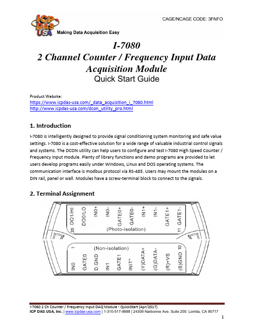
I-70802 Channel Counter / Frequency Input DataAcquisition ModuleQuick Start GuideProduct Website:https:///_data_acquisition_i_7080.html/dcon_utility_pro.html1. IntroductionI-7080 is intelligently designed to provide signal conditioning system monitoring and safe value settings. I-7080 is a cost-effective solution for a wide range of valuable industrial control signals and systems. The DCON utility can help users to configure and test I-7080 High Speed Counter / Frequency Input module. Plenty of library functions and demo programs are provided to let users develop programs easily under Windows, Linux and DOS operating systems. The communication interface is modbus protocol via RS-485. Users may mount the modules on a DIN rail, panel or wall. Modules have a screw-terminal block to connect to the signals.2. Terminal Assignment3. Block/ Wiring Diagram4. Default SettingsDefault settings for the I-7080 module is as follows: •address=01•baud rate=9600•checksum disable•data=1 start+8 data+1 stop(no parity)•type=50 (counter input)•alarm=hi alarm on counter 0 & counter 1 (I-7080)5. ConfigurationTo install the module, follow the steps below:1. Connect the analog output.2. Connect the module to the RS-485 network using the DATA+ and DATA- terminals. If the host is only equipped with an RS-232 interface, then an RS-232 to RS-485 converter will be required.3. Connect the module to the power supply using the +Vs and GND terminals. Note that the voltage supplied should be in the range of +10 to +30V DC.4. Open DCON utility proclick on COM port(first icon).It can select multi-options such as Baud Rate, Protocol, Checksum, and Format to search module. The default settings for the module can be found in Section 3. Click OK after selecting the COM port setting.5. DCON utility pro will search for the selected COM port according the setting previously set. DCON Utility Pro supports DCON and Modbus protocol for all ICPDAS and the others modules.6. Configuration I/O module setting on PC7. For I-7000 modules, DCON utility pro terminal can send command to the module. See user manual Sections 2 for details command.Configure the module: sending the %AANNTTCCFF command. See user manual Section 2 for details.Read data from the input channels: send either the #AA or #AAN command to the module.8. If user doesn’t know command, user can select Address and ID, it will show some refer commands as below. User can select necessary command to test or debug modules.。
LM-79测试报告
IES LM-79 测试报告a)Date and testing agencyb)Manufacturer's name and designation of SSLproduct under testc)Measurement quantities measured(totalluminous flux,luminous efficacy,etc.)d)Rated electrical values(clarify AC(frequency)or DC)and nominal CCT of the SSL product testede)Number of hours operated prior tomeasurement(0h for rating new products) f)Total operating time of the product formeasurements including stabilizationg)Ambient temperatureh)Orientation(burning position)of SSL productduring testi)Stabilization timej) Photometric method or instrument used (spherephotometer,sphere-spectroradiometer, or oniophotometer)k) Designation and type of reference standard used(wattage, lamp type, intensitydistribution type -omni-directional/directional) and its traceability a) 日期和测试机构b) 制造商名称和被测产品名称c) 测试量(总光通量,光效等)d)额定电特性(AC(频率)或DC)和SSL产品的标称色温e)测试前的工作时间(新产品为0H)f)测试产品的总操作时间包括稳定时间g)环境温度h)SSL产品在测试时的方向(点亮位置)i)稳定时间j)使用的光度方法或仪器(球-光度计,球-辐射度计,或分布式光度计)k)使用的参考标准的名称及类型(W,灯类型,光强分布类型-全方位/指向性)和可追溯性IES LM-79 测试报告l) Correction factors applied (e.g., spectralmismatch,self-absorption, intensity istribution,etc.)m) Photometric measurement conditions (for sphere measurement, diameter of the sphere, coating reflectance, 4p or 2p geometry. Forgoniophotometer, photometric distance.)n) Measured total luminous flux (lm) and input voltage(V), current (A), and power (W) of each SSLproducto) Luminous intensity distribution (if applicable). p) Color quantities (chromaticity coordinates, CCT and/or CRI for white light products)q) Spectral power distribution (if applicable)r) Bandwidth of spectroradiometer, if spectral distribution and/or color quantities arereporteds) Equipment usedt) Statement of uncertainties (if required)u) Deviation from standard operating procedures, if any l) 应用的修正因子(例如,光谱失配,自吸收,光强分布等)m) 光度测试环境(积分球测试,须标明积分球半径、涂层反射率、4π或2π几何体。
Thermo Scientific Richard-Allan Scientific Dehydra

Richard-Allan ScientificSubsidiary of Thermo Fisher Scientific 4481 Campus Drive, Kalamazoo, MI 49008Phone: 1 (800) 522-7270 Phone: + 1 (269) 544-5600/pathologyAnatomical Pathology©2013 Thermo Fisher Scientific Inc. All rights reserved. All trademarks are the property of Thermo Fisher Scientific Inc. and its subsidiaries.Thermo Shandon LimitedSubsidiary of Thermo Fisher Scientific Tudor Road, Manor Park,Runcorn, Cheshire WA7 1TA, UK Phone: +44 (0) 1928 534 050Fax: + 44 (0) 1928 534 049Thermo Scientific ™ Richard-Allan Scientific Dehydrant Alcohol Instructions for UseThermo Scientific Richard-Allan Scientific Dehydrant Alcohol product lines are specifically designed for tissue processing and staining of histological and cytological specimens. The products are a clear, colorless blend of ethyl, isopropyl, and methyl alcohol that in some cases have trace amounts of other denatured materials. All Dehydrant Alcohol products are non-controlled substances and do not require record keeping. The formulations are readily miscible with water to form any desired grade of alcohol and can be used with all clearing reagents. The Dehydrant Alcohol line can be used with both open and closed tissue processors. Protective gloves should be worn and work should be performed in a ventilated area. Dehydrant Alcohol is a flammable product and must be stored in a flammable fire cabinet. The Dehydrant Alcohol product line can also be used for hydrating and dehydrating tissue sections during staining. They can be used with all special stains that require dehydra-tion, as solvents for preparing special stains, and immunohistochemical procedures that are compatible with alcoholic dehydrants. The Dehydrant Alcohol product line can be substituted in place of any alcohol you are presently using for hematoxylin and eosin-y staining. They are compatible with all manual procedures and automatic stainers.Tissue Processing Instructions For UseDehydrant Alcohol has shown best results on closed tissue processors when heat is not used during the nor-mal dehydration process. Vacuum has been viewed as an asset during all phases of tissue processing, includ-ing dehydration. The time in each dehydration station should be no less that 30 minutes and no more than 1 hour for a normal, multiple tissue type and thickness processing run. Dehydrant Alcohol is also recommended to be used in the cleaning cycle of a closed tissue processor in an anhydrous concentration.The laboratory should develop a product rotation and change out schedule that adheres to the policies of their department.ProtocolsThe following tissue processing schedule is recommended for the average hospital surgical load.Station Solution Time 1 10% Neutral Buffered Formalin holding 2 10% Neutral Buffered Formalin 1 hour 3 Pen-Fix™ or 80% Dehydrant 40 minutes 4 95% Dehydrant 40 minutes 5 95% Dehydrant 40 minutes 6 100% Dehydrant 40 minutes 7 100% Dehydrant 40 minutes 8 100% Dehydrant 40 minutes 9 Clearing Reagent 1 hour 10 Clearing Reagent 1 hour 11 Paraffin 1 hour 12 Paraffin 1 hour Note: This procedure may not fit every situation. Modifications may be necessary.When small biopsy or thin tissue specimens (less than 2 mm in thickness) are processed separately, the fol-lowing tissue processing schedule is recommended. Tissues are assumed to be fixed. If not, stations 1 and 2 should utilize 10% Neutral Buffered Formalin for a minimum of 30 minutes each.Station Solution Time 1 10% Neutral Buffered Formalin (30 minutes)2 10% Neutral Buffered Formalin (30 minutes)3 Pen-Fix or 80% Dehydrant 10 minutes 4 95% Dehydrant 10 minutes 5 95% Dehydrant 10 minutes 6 100% Dehydrant 10 minutes 7 100% Dehydrant 10 minutes 8 100% Dehydrant 10 minutes 9 Clearing Reagent 15 minutes 10 Clearing Reagent 15 minutes 11 Paraffin 20 minutes 12 Paraffin 20 minutes Note: This procedure may not fit every situation. Modifications may be necessary.Staining Instructions for UseIt is recommended that three stations of 100% Dehydrant Alcohol for 1 minute each follow the clearing reagent after deparaffinization, and at least one station of 95% Dehydrant Alcohol be used prior to the water rinse.After staining is completed, slides should be dehydrated in three stations of 100% Dehydrant Alcohol for 1 minute each before clearing. This will assure complete dehydration, which results in maximum slide clarity.A 95% Dehydrant Alcohol can be used prior to the eosin-y to eliminate water carryover into the stain. Another 95% alcohol can be used after the eosin-y stain to assist in lighting the eosinophilic hue if desired.The laboratory should develop a product rotation and change out schedule that adheres to the policies of their department.ProtocolThe following tissue staining schedule is recommended for the average hospital surgical load.Station Solution Time 1 Clearing Reagent 3 minutes 2 Clearing Reagent 3 minutes 3 Clearing Reagent 3 minutes 4 100% Dehydrant 1 minute 5 100% Dehydrant 1 minute 6 100% Dehydrant 1 minute 7 95% Dehydrant 1 minute 8 Rinse in running tap water Briefly 9 Deionized or distilled water Rinse 10 Hematoxylin Chosen Time 11 Running tap water Rinse off excess stain 12 Acid Rinse Chosen Time 13 Rinse in running tap water 30 seconds (agitate)14 Bluing Reagent 1 minute 15 Rinse in running tap water 1 minute 16 95% Dehydrant Rinse 17 Eosin-Y Chosen Time 18 100% Dehydrant 1 minute 19 100% Dehydrant 1 minute 20 100% Dehydrant 1 minute 21 Clearing Reagent 1 minute 22 Clearing Reagent 1 minute 23 Clearing Reagent 1 minute Note: This procedure may not fit every situation. Modifications may be necessary.Warnings and PrecautionsSee Material Safety Data Sheets for warnings and precautions, as well as R & S code definitions.See container labels for warnings and precautions.Order InformationProductSizeQty. REF Dehydrant Alcohol 100% 1 gal. (3.79L) bottle 4/cs. 6201Dehydrant Alcohol 95% 1 gal. (3.79L) bottle 4/cs. 6301Dehydrant Alcohol 95% 55 gal. (208L) drum 2/cs. 6355Dehydrant Alcohol 80% 1 gal. (3.79L) bottle 4/cs. 6401Dehydrant Alcohol 70%1 gal. (3.79L) bottle4/cs.6501IS8111 R1/13。
蓝牙协议分析仪

Explorer ™
Bluetooth® Instant Protocol Analysis
All-Channel, Full-Spectrum, Concurrent Synchronous Capture of Bluetooth 2.1 BR/EDR, Low Energy and HCI traffic
ch77ch78slot3slot4time?ellisysbluetoothexplorer400uniqueellisysfeatures???????robustcapturenonintrusivesniffingzeroconfigurationcaptureanypacketatanytimecaptureanunlimitednumberofneighboringpiconetsconcurrentandsynchronouscaptureofbredrandlowenergytrafficconcurrentandsynchronouscaptureofbredrandhcitrafficwithoutunexpectedlossofsynchronizationevertheanalyzerdoesnotinteractwithordisturbpiconetsundertestsimplyclicktherecordbuttonandstartsniffingincludingallpacketsfrompaginginquiryandroleswitchwithasingleunitwithasingleunitwithasingleunitproducthighlights?????????visualizeevolutionofpiconetsandscatternetsliveinellisysinstantpiconetviewvisualizeallpacketswith18thsymbolaccuracyinellisysinstanttimingviewdecodeallprotocolsandprofilesautomaticallyexportbluetoothdatatovariousformatsincludingaudiowaveformsseerelationshipsbetweenprotocollevelsandsequencesofdifferentprotocolsclearlyinasinglevieworinmultiplesynchronizedviewsdeterminepincodesautomaticallyanddecryptdataontheflyfreelifetimesoftwareupdatesnomaintenancefeesfree
- 1、下载文档前请自行甄别文档内容的完整性,平台不提供额外的编辑、内容补充、找答案等附加服务。
- 2、"仅部分预览"的文档,不可在线预览部分如存在完整性等问题,可反馈申请退款(可完整预览的文档不适用该条件!)。
- 3、如文档侵犯您的权益,请联系客服反馈,我们会尽快为您处理(人工客服工作时间:9:00-18:30)。
LM-79 and LM-80IntroductionLight emitting diodes (LEDs) are a relatively new and unique source for outdoor lighting. They are more reliant upon effective thermal management than any previous source, more of a directional source, and have to be designed and tested as an entire lighting system. Therefore, LEDs require new guidelines and practices for testing. There also needs to be a correlation between how LED manufacturers test their LEDs and how fixture manufacturers test their LED fixtures. In response, the Illuminating Engineering Society of North America or IESNA developed LM-79-08 and LM-80-08 for LED fixture and LED device testing.This Information Brief provides specifiers, engineers, lighting designers, commercial property owners, municipalities and utilities with an understanding of these documents. As an industry leader, Philips® remains at the forefront of LED technology and associated industry documentation. Philips Lumileds® applies LM-80-08 to their LUXEON LEDs, including the Rebel, and Philips HADCO® applies LM-79-08 to their outdoor LED lighting fixtures. Both companies remain active members of the IESNA in the development of methods and guidelines that help advance the use of LEDs in outdoor lighting.The IESNAThe IESNA is a 100+ year old lighting industry group with membership that includes manufacturers (both sources and fixtures), lighting designers and architects, utilities, and others affiliated with lighting such as consultants, government, researchers and educators.1 Both Philips and HADCO are active, contributing members of the IESNA.As a lighting organization the IESNA plays an important role in developing lighting documentation. Its chief publication is The Lighting Handbook which covers topics from light, lighting and vision to performance guidelines for indoor and outdoor lighting fixtures and applications. The IESNA also publishes numerous other lighting documents including: DG or Design GuidesLM or Lighting MeasurementsRP or Recommended PracticesTM or Technical Memorandumsall of which are utilized by lighting engineers, lighting professionals, lighting designers and LED and fixture manufacturers. Two LED LMs are LM-79-08 and LM-80-08; they will be covered in reverse order for reasons that will be evident after reading this IB.LEDs 101 – A RefresherBefore getting into the LMs, a refresher of LEDs is helpful. LEDs are solid state electronic devices that directly convert electricity into light with heat as a by-product. See Figure 1.Figure 1. Electrical model of an LED.Illustration courtesy of IESNA TM-16-05.The light is emitted forward while the heat occurs in the P/N junction where the work of converting electricity into light occurs. This junction temperature or T J heat must be conducted through the thermal pad and away from the LED. See Figure 2.Figure 2. Cross-section of a LUXEON ® Rebel LED. Illustration courtesy of Philips Lumileds Lighting Company.conducted heat (T J )In contrast, traditional sources rely upon secondary process to produce light such as heating a filament (incandescent), causing a gas to glow (fluorescent), or igniting a gas in an arc tube (HID or High Intensity Discharge). For a detailed discussion of LED light generation and the relationship between LED performance and heat, see HADCO’s Information Brief entitled LED Thermal Management.Since LEDs are solid state and directly convert electricity to light, their lumen maintenance is better than traditional sources. Lumen maintenance is a measure of how well a light source maintains its lumen output over time, typically shown as a percentage of initial light output. Typical LED lumen maintenance is 70% for 50,000+ hours – a marked improvement over traditional sources. As an example, compare LEDs to pulse start Metal Halide (p.s. MH) – see Figure 3 on the following page. The p.s. MH lamp has to be replaced four times within the same 50,000 hours, and the LED’s lumen maintenance remains above 70% while the p.s. MH lamp drops down to 50% lumen maintenance toward the end of its life.70% lumen maintenance means the LEDs will still produce 70% of their initial light output, or only 30% lumen degradation. According to the Lighting Research Center, this is “…close to the threshold for detecting gradual reductions in light output. Research shows also that reductions to 70% of initial light output are considered acceptable by the majority of occupants within a space.”2Figure 3. Lumen maintenance of LED versus pulse start Metal Halide.LM-80-08 for the LEDs themselvesLM-80-08 Approved Method: Measuring Lumen Maintenance of LED Light Sources was published by the IESNA Solid State Lighting (SSL) Subcommittee in the third quarter of 2008. Simply referred to as LM-80, this document covers lumen maintenance measurement for inorganic LED-based packages, arrays, and modules3; it does not cover any other aspect of LED performance. See the Appendix at the end of this IB for definitions of terms.One of the key reasons for the development of LM-80 is due to differences in measuring LED performance criteria. LED manufacturers typically measure LEDs in pulse mode operation with no heat sink. The pulse is very short – typically 10 or 20 milliseconds (that is, thousandths of a second) – which will not heat up the LED; therefore, no heat sink is required and T J can be assumed to be equal to ambient temperature T A (typically held constant at 25°C). This is useful for doing high yield LED measurements quickly. This also explains why LED manufacturer data sheets typically show LED performance for T J = 25°C.In contrast, LED fixture manufacturers measure LED performance in situ, which means while it is in their fixture. Under these conditions, the LED is operated in constant DC mode and there are typically numerous LEDs configured together often in close proximity to one another, elevating T J above 25°C. This elevated T J affects the photometric and colorimetric performance of the LEDs. In order to compare “apples to apples”, a new testing criteria needed to be developed – enter LM-80.LM-80 prescribes uniform test methods for LED manufacturers under controlled conditions for measuring LED lumen maintenance while controlling the LED’s T S or case temperature, the DC forward voltage and forward current to the LED. LM-80 requires 55°C, 85°C and one other T S chosen by the LED manufacturer. It also requires lumen maintenance data out to at least 6,000 hours of constant DC mode (not pulse mode) operation4.Philips Lumileds chose 110°C for the third T S for their Rebel LED and they have recorded data out to 10,000 hours which is the preferred duration in LM-80. Based upon LM-80 data, LED manufacturers then extrapolate lumen maintenance out to tens of thousands of hours; Philips Lumileds goes out to 50,000 hours and beyond. While LM-80 does not specify the extrapolation method, many LED manufacturers use more conservative exponential extrapolation due to the exponential behavior of LEDs and most electronic components. The SSL Subcommittee is working on TM-21 which will standardize this extrapolation method.The data resulting from LM-80 measurements are matrices of lumen maintenance values. LED fixture manufacturers use this data in combination with their UL in-situ thermal testing to predict the lumen maintenance of the LEDs when used in their fixtures and, subsequently, the lumen maintenance of the LED fixtures themselves. For example, if we measure 85°C T S at the hottest Rebel LED in one of our fixtures, then we look up that particular data set from Philips Lumileds to determine the LED fixture’s lumen maintenance based upon and correlated with the LED’s lumen maintenance at that same T S. Fixture manufacturers also use the data to predict LED color stability over time at the various T S temperatures.LM-79-08 for the LED fixtureLED lumen maintenance and color stability are only part of the puzzle; it is helpful to characterize the performance of LEDs in fixtures so that the entire system is considered. That’s where LM-79 comes in.LM-79-08 Approved Method: Electrical and Photometric Measurements of Solid-State Lighting Products was published by the IESNA Solid State Lighting (SSL) Subcommittee in the first quarter of 2008. LM-79 covers photometric and colorimetric performance as well as electrical power measurements for inorganic LED fixtures5. LM-79 prescribes uniform test methods for LED fixture manufacturers under controlled conditions using LED fixtures as they would be manufactured for production.Unlike traditional sources which are typically tested using relative photometry with test lamps and ballasts, LED fixtures are tested using absolute photometry with production LEDs and fixtures in the orientation in which it will be installed6 to ensure a more true test of LED performance when in situ. For a detailed discussion of absolute photometry, see HADCO’s Information Brief entitled Understanding Relative and Absolute Photometry. As previously discussed, LEDs operated in situ will perform differently due to the elevated T J which will be further impacted by fixture orientation and thermal conditions; if the LED array or module were removed from the fixture, its performance would change. This is precisely why absolute photometry is a must for LED fixtures.LM-79 testing is typically performed with either an integrating sphere for all photometric and colorimetric measurements or an integrating sphere in combination with a goniophotometer. The integrating sphere is recommended for colorimetric measurements; alternately, a gonio-spectroradiometer or gonio-colorimeter may be used.HADCO has a custom designed goniophotometer lab and equipment (again, see the Understanding Relative and Absolute Photometry IB for more details) where we test LED fixtures following LM-79 procedures. We also test key LED fixtures in independent DOE-approved labs – look for the .ies photometric files on our web site that indicate LM-79.ConclusionWith over 150 years of combined lighting and LED experience between them, Philips and HADCO understand LED technology, fixture manufacturing and LED and fixture testing. Our vertical integration enables us to better understand everything from the LED device itself to its proper use in fixtures. As active participants in the IESNA, both companies will continue to engage lighting organizations and other lighting professionals to ensure that we keep developing and manufacturing LED and other products with optimum performance that stand the test of time. To learn more about HADCO’s growing line of LED fixtures and our entire commercial and landscape product line, go to .Appendix – DefinitionsThe definitions in this Appendix are per ANSI / IESNA RP-16-05 Addendum a Nomenclature and Definitions for Illuminating Engineering, IES Nomenclature Committee, New York: Illuminating Engineering Society of North America, 2008.Please refer to the latest edition of this document for updates and revisions.LED die – A small block of semi-conducting material on which a given functional circuit is fabricated. {Author’s note: Also referred to as an LED chip; the light emitting part.}The following three definitions are for devices that do not include a power source and are not connected directly to the branch circuit.LED package – An assembly of one or more LED dies that contains wire bond connections, possibly with an optical element and thermal, mechanical, and electrical interfaces. {Author’s note: What we commonly refer to as the LED itself.}LED array – An assembly of LED packages on a printed circuit board or substrate, possibly with optical elements and additional thermal, mechanical, and electrical interfaces.LED module – A component part of an LED light source that includes one or more LEDs connected to the load side of LED power source or LED driver. Electrical, electronic, optical, and mechanical components may also be part of an LED module.Appendix – Definitions <continued>Power source – A transformer, power supply, battery, or other device capable of providing current, voltage, or power within its design limits. This device contains no additional control capabilities.Power supply – An electronic device capable of controlling current, voltage, or power within design limits.LED control circuitry – Electronic components located between the power source and the LED array designed to limit voltage and current, to dim, to switch, or otherwise control the electrical energy to the LED array. The circuitry does not include a power source.LED driver – A power source with integral LED control circuitry designed to meet the specific requirements of a LED lamp or a LED array.References1. IESNA web site , About Us page, 2009.2. Bullough, J. et al., ASSIST recommends… LED Life for General Lighting: Definition of Life, Volume 1, Issue 1. Troy, NY: Lighting Research Center, Rensselaer Polytechnic Institute, February 2005.3. Subcommittee on Solid State Lighting of the IESNA Testing Procedures Committee, Approved Method: Measuring Lumen Maintenance of LED Light Sources, LM-80-08, New York: Illuminating Engineering Society of North America, 2008.4. Ibid.5. Subcommittee on Solid State Lighting of the IESNA Testing Procedures Committee, Approved Method: Electrical and Photometric Measurements of Solid-State Lighting Products, LM-79-08, New York: Illuminating Engineering Society of North America, 2008.6. Ibid.November 2009, Rev. 2©2009 HADCO, a Philips group brand. All rights reserved. Product specifications are subject to change without notice. HADCO is a registered trademark of HADCO.。