(TP001)_I-5__2_x_High-Fidelity_Master_Mix_20170608064329040
基于ATML标准的测试信息描述研究

自动化测试计算机测量与控制.2009.17(8) Computer Measurement &Control ・1467・收稿日期:2009201204; 修回日期:2009202203。
作者简介:钱 锋(19792),男,河北石家庄人,在读博士研究生,主要从事复杂电子装备自动测试等方向的研究。
文章编号:167124598(2009)0821467203 中图分类号:TP273文献标识码:A基于ATML 标准的测试信息描述研究钱 锋,孟 晨,王 成(军械工程学院导弹工程系,河北石家庄 050003)摘要:当前测试领域缺乏一个广为接受的测试信息交换标准,这已成为自动测试系统向前发展的一个瓶颈,为了解决此问题,IEEE 发布了A TML 标准,该标准使用XML 语言进行A TS 的测试信息的标准化交换;文章首先介绍了A TML 标准的目标与具体组成,然后以测试结果为例,实现了基于A TML 标准的测试结果信息的标准化描述;为了方便测试软件的开发,本文开发了测试结果组件,测试软件中直接调用测试结果组件以生成符合A TML 标准的测试结果文件。
关键词:A TML ;XML Schema ;测试结果R esearch on T est Information Description B ased on ATML StandardQian Feng ,Meng Chen ,Wang Cheng(Department of Missile Engineering ,Ordnance Engineering College ,Shijiazhuang 210094,China )Abstract :Currently ,t he testing domain is short of a standard which is accepted widely for description and exchange of test information.In order to solve t his problem ,t he IEEE issued standard for Automatic Test Markup Language (A TML )for depicting Automatic Test E 2quipment and Test information.Firstly ,t he A TML standard was introduced.Then t he paper took test result as example to explain how to describe t he test information using A TML standard.Finally ,t he component of test result is developed to make a test result ’s document au 2tomatically according to A TML standard .K ey w ords :A TML ;XML Schema ;test result0 引言当前,自动测试系统(A TS )软件中不同信息实体之间都是紧耦合的,各信息实体之间缺乏标准化的电子数据交换(EDI ,Electrical Data Interchange )格式,协同工作的能力较差。
BGP路由黑洞
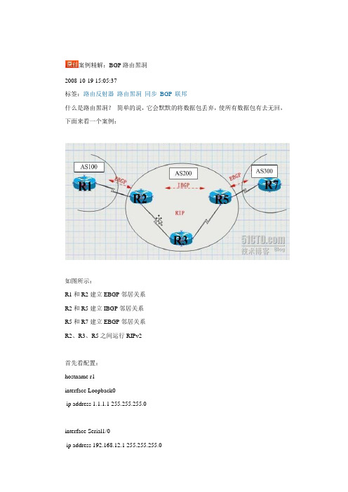
案例精解:BGP路由黑洞2008-10-19 15:05:37标签:路由反射器路由黑洞同步BGP联邦什么是路由黑洞?简单的说,它会默默的将数据包丢弃,使所有数据包有去无回,下面来看一个案例:如图所示:R1和R2建立EBGP邻居关系R2和R5建立IBGP邻居关系R5和R7建立EBGP邻居关系R2、R3、R5之间运行RIPv2首先看配置:hostname r1interface Loopback0ip address 1.1.1.1 255.255.255.0interface Serial1/0ip address 192.168.12.1 255.255.255.0serial restart-delay 0router bgp 100no synchronizationbgp router-id 1.1.1.1bgp log-neighbor-changesnetwork 1.1.1.0 mask 255.255.255.0network 192.168.12.0neighbor 2.2.2.2 remote-as 200neighbor 2.2.2.2 ebgp-multihop 255neighbor 2.2.2.2 update-source Loopback0 no auto-summary!ip route 2.2.2.0 255.255.255.0 192.168.12.2hostname r2interface Loopback0ip address 2.2.2.2 255.255.255.0!interface Serial1/0ip address 192.168.23.2 255.255.255.0serial restart-delay 0!interface Serial1/1ip address 192.168.12.2 255.255.255.0serial restart-delay 0!interface Serial1/2ip address 192.168.24.2 255.255.255.0serial restart-delay 0!router ripversion 2network 2.0.0.0network 192.168.23.0no auto-summary!router bgp 200no synchronizationbgp log-neighbor-changesnetwork 192.168.12.0network 192.168.23.0neighbor 1.1.1.1 remote-as 100neighbor 1.1.1.1 ebgp-multihop 255neighbor 1.1.1.1 update-source Loopback0 neighbor 5.5.5.5 remote-as 200neighbor 5.5.5.5 update-source Loopback0 neighbor 5.5.5.5 next-hop-selfno auto-summary!ip route 1.1.1.0 255.255.255.0 192.168.12.1hostname r3interface Loopback0ip address 3.3.3.3 255.255.255.0!interface Serial1/0ip address 192.168.35.3 255.255.255.0serial restart-delay 0!interface Serial1/1ip address 192.168.23.3 255.255.255.0 serial restart-delay 0router ripversion 2network 3.0.0.0network 192.168.23.0network 192.168.35.0no auto-summaryhostname r5interface Loopback0ip address 5.5.5.5 255.255.255.0!interface FastEthernet0/0no ip addressshutdownduplex half!interface Serial1/0ip address 192.168.57.5 255.255.255.0 serial restart-delay 0!interface Serial1/1ip address 192.168.35.5 255.255.255.0 serial restart-delay 0!interface Serial1/2ip address 192.168.45.5 255.255.255.0 serial restart-delay 0!interface Serial1/3no ip addressshutdownserial restart-delay 0!router ripversion 2network 5.0.0.0network 192.168.35.0no auto-summary!router bgp 200no synchronizationbgp log-neighbor-changesbgp confederation identifier 200neighbor 3.3.3.3 remote-as 200neighbor 7.7.7.7 remote-as 300neighbor 7.7.7.7 ebgp-multihop 255neighbor 7.7.7.7 update-source Loopback0 no auto-summary!ip route 7.7.7.0 255.255.255.0 192.168.57.7interface Serial1/1ip address 192.168.57.7 255.255.255.0serial restart-delay 0!interface Serial1/2no ip addressshutdownserial restart-delay 0!interface Serial1/3no ip addressshutdownserial restart-delay 0!router bgp 300no synchronizationbgp log-neighbor-changesneighbor 5.5.5.5 remote-as 200neighbor 5.5.5.5 ebgp-multihop 255no auto-summary!ip route 5.5.5.0 255.255.255.0 192.168.57.5现在查看R1的路由表r7#sh ip routeB 1.1.1.0 [20/0] via 5.5.5.5, 00:02:54 //为节约篇幅未完整显示可见R7学到了R1的路由,从表面上看这个实验很完美,达了目的,然而这时问题出现了,作个测试,在R7上PING R1r7#ping 1.1.1.1Type escape sequence to abort.Sending 5, 0-byte ICMP Echos to 7.7.7.7, timeout:.....这究竟是怎么回事呢?原来,我们在R5上关闭了同步,这时它会将一条并没有优化的路由传送给R7,当R7要发向R1发包时,它看到R5是它的下一跳,于是将包发给R5,然后R5又查看它的路由表,发现到R1的下一跳是R2,并继续查找,发现在通过R3可以达到R2,于是它将数据送给R3,这时问题出现了,因为R3没有运行BGP,它不知道R1怎么走,于是它将数据包丢弃,从而造成路由黑洞。
11汉明码编解码实验
加错位置 从 0 位置加错 从 1 位置加错 从 2 位置加错 从 3 位置加错 ……. 从 15 位置加错
加错位置 加 0 位错 加 1 位错 加 2 位错 加 3 位错
从 SW103-6,SW103-5,SW103-4,SW103-3 指示的位置开始,每帧加错的位数有 SW103-2,SW103-1 的状 态决定。 5、编码输出设置 D116,D115,D114,D113,D112,D111,D110,D109,D108,D107,D106,D105,D104,D103, D102,D101 为 16 位编码输出位。TP102 和 TP103 分别可以测量编码输出的帧和对应该帧的时钟信号。 6、解码方式选择 SW201-3,SW201-2,SW201-1 000 001 010 解码方式 汉明码解码 CRC 解码 BCH 码解码
3
S1S2S3 001 010 100 011
错误位置
S1S2S3 101 110 111 000
错误位置
a0 a1 a2 a3
a4 a5 a6
无错
下表是汉明码编码信息位与监督位的对应表: 信息位 监督位 信息位 监督位
a6 a5 a4 a3
0000 0001 0010 0011 0100 0101 0110 0111
如图所示:编码输入为 0001,编码输出为 0001011。 2、汉明解码 (1)端口设置 cs_hanming:输入汉明解码设置使能位,’1’电平有效; datain_hanming:输入 7 位汉明编码位; error_hanming:输出错误标志位,当信道加错时,输出‘1’电平表示信道有错; dataout_hanming:输出 4 位汉明解码位。 (2)主要程序 --产生错误图样 sel(2)<=(datain_hanming(6) xor datain_hanming(5)) xor (datain_hanming(4) xor datain_hanming(2)); sel(1)<=(datain_hanming(6) xor datain_hanming(5)) xor (datain_hanming(3) xor datain_hanming(1)); sel(0)<=(datain_hanming(6) xor datain_hanming(4)) xor (datain_hanming(3) xor datain_hanming(0)); --输出错误序列 with sel select
中国石油大学期末考试复习题 070109数据结构-18

《数据结构》综合复习资料一、填空题1、数据结构是()。
2、数据结构的四种基本形式为集合、()、()和()。
3、线性结构的基本特征是:若至少含有一个结点,则除起始结点没有直接前驱外,其他结点有且仅有一个直接();除终端结点没有直接()外,其它结点有且仅有一个直接()。
4、堆栈的特点是(),队列的特点是(),字符串中的数据元素为()。
5、字符串s1=“I am a student!”(单词与单词之间一个空格),s2=“student”,则字符串s1的长度为(),串s2是串s1的一个()串,串s2在s1中的位置为()。
6、KMP算法的特点:效率较();()回溯,对主串仅需要从头到尾扫描()遍,可以边读入边匹配。
7、广义表((a),((b),c),(((d))))的长度为(),表头为(),表尾为()。
8、ADT称为抽象数据类型,它是指()。
9、求下列程序的时间复杂度,并用大O表示方法表示()。
for( i=1 ; i<=n ; + + i)for( j=1 ; j<=i; + + j ){ ++x;a[i][j] = x;}10、以下运算实现在链栈上的退栈操作,请在_____处用适当句子予以填充。
int Pop(LstackTp *ls,DataType *x){ LstackTp *p;if(ls!=NULL){ p=ls;*x= ;ls= ;;return(1);}else return(0);}11、用堆栈求中缀表达式a+b*c/d+e*f的后缀表达式,求出的后缀表达式为()。
12、C语言中存储数组是采用以()为主序存储的,在C语言中定义二维数组float a[8][10],每个数据元素占4个字节,则数组共占用()字节的内存。
若第一个数据元素的存储地址为8000,则a[5][8]的存储地址为()。
13、含零个字符的串称为()串,用 表示。
其他串称为()串。
任何串中所含字符的个数称为该串的()。
STM32固件库使用手册的中文翻译版
因为该固件库是通用的,并且包括了所有外设的功能,所以应用程序代码的大小和执行速度可能不是最优 的。对大多数应用程序来说,用户可以直接使用之,对于那些在代码大小和执行速度方面有严格要求的应 用程序,该固件库驱动程序可以作为如何设置外设的一份参考资料,根据实际需求对其进行调整。
1.3.1 变量 ................................................................................................................................................ 28 1.3.2 布尔型 ............................................................................................................................................ 28 1.3.3 标志位状态类型 ........................................................................................................................... 29 1.3.4 功能状态类型 .............................................................................................................
RTK_P2P_WFD_Programming_guide
Realtek Wi-Fi Direct/Miracast Programming GuideSupport Linux Kernel <= 2.6.34Date: 2013/01/29Version: 1.2Document V ersion NoteV1.2 1. Refine the P2P description2. Added P2P commands3. Added Miracast commandsWi-Fi Direct ( P2P ) is the new technology developed by Wi-Fi Alliance. It is a solution for Wi-Fi device-to-device connectivity. And it is also backward compatible with existing Wi-Fi Certified devices.The following picture is the overview for Wi-Fi Direct architecture of Realtek Linux Wi-Fi Direct software. This software architecture is based on the linux standard interface “wireless extension”. If the system platform will perform the P2P/Miracast feature on cfg80211/Android, please refer to another document (Miracast on Android.pdf).Figure1: Software Architecture for Realtek Linux Wi-Fi DirectBasically, there are two roles in the Miracast connection. One is Miracast source device; another is Miracast display (sink) device. The TDLS & Wi-Fi Direct can be used to establish the Miracast connection. The Wi-Fi Direct is mandatory feature for Miracast, TDLS is optional. This document will focus on the Wi-Fi Direct technology when creating the Miracast connection.“User Interface App (UI)” is an application which should be designed by customer for their product. UI should use the iwpriv application to get/set whole the P2Pinformation from/to the Realtek Wi-Fi driver. Iwpriv application is available in the wpa_supplicant_hostapd folder and we also provide the porting guide under document folder. (Please refer to the Wireless tools porting guide.doc)Of course, the UI can use the iwpriv application to issue the P2P information to driver based on the Wi-Fi Direct APIs described in this document.wpa_cli and wpa_supplicant are the standard application to handle whole the 802.11 station mode connection. Hostapd and hostapd_cli are also the standard application to handle whole the 802.11 AP mode connections.In usual, there are 4 stages in the Wi-Fi Direct scenario.1.“Device Discovery”2.“Provision Discovery”3.“Group Formation”4.“Provisioning”The following picture will provide the overall concept for Wi-Fi Direct functionality and it will also contain these 4 stages described above.Figure2: Wi-Fi Direct OverviewThe figure2 describes the basic Wi-Fi Direct scenario and this document will use this figure to explanation the Wi-Fi Direct functionality and APIs.1. Enable P2PIn this case, there are two Wi-Fi devices which both support the Wi-Fi Direct functionality. We can use the iwpriv to enable the Wi-Fi Direct function of Realtek Wi-Fi driver (enable P2P).#> iwpriv wlan0 p2p_set enable=n“wlan0”is the network interface for Realtek Wi-Fi device on the system. “p2p_set” command is used to pass the settings information to the driver. “enable” is the actual command to tell the driver which information the application is trying to set.“n” is a number to set the P2P functionality.“n=0” means to disable the P2P functionalityEx: #> iwpriv wlan0 p2p_set enable=0“n=1”means to turn the P2P functionality on and the Wi-Fi driver will be the P2P device mode.Ex: #> iwpriv wlan0 p2p_set enable=1“n=2”means to turn the P2P functionality on and the Wi-Fi driver will be the P2P client modeEx: #> iwpriv wlan0 p2p_set enable=2“n=3”means to turn the P2P functionality on and the Wi-Fi driver will be the P2P group owner mode.Ex: #> iwpriv wlan0 p2p_set enable=3“n”had been defined in the P2P.h file of the document folder. This document also copies that definition here for the reference.enum P2P_ROLE {P2P_ROLE_DISABLE = 0,P2P_ROLE_DEVICE = 1,P2P_ROLE_CLIENT = 2,P2P_ROLE_GO = 3};The Realtek Wi-Fi driver supports the concurrent mode. It means there are two network interfaces on your system when the Wi-Fi driver is installed on your platform. However, the P2P functionality can just be enabled on one network interface. The P2P functionality can’t be enabled on both two network interface at the same time. For example: If you had enabled the P2P functionality on wlan0, the Wi-Fi driver will ignore the P2P enable instruction automatically when you try to enable the P2P functionality on wlan1.2. Scanning P2P DeviceAfter enabling the P2P functionality of the Wi-Fi driver, the P2P device1 got to find out how many other P2P devices exist in the environment. The UI can do the scan via wpa_supplicant or iwlist command.For wpa_supplicant:Ex: #> wpa_cli scan // Ask wpa_supplicant to do the scanningEx: #> wpa_cli scan_results // Get the scanning resultFor iwlist:Ex: #> iwlist wlan0 scan // Issue the scanning request to driver and result the scanning result.When P2P is enabled, the Wi-Fi driver can provide the different scanning result based on the “scan_type” command.Ex: #> iwpriv wlan0 p2p_set scan_type=nWhen n=0, the Wi-Fi driver will provide the device list which has the P2P capability. When n=1, the Wi-Fi driver will list all the Access Points and P2P devices (This case is related to the WiDi Gen2 NB). When n=2, the Wi-Fi driver will provide the Miracast source device list if the Wi-Fi driver is set to Miracast sink device. When n=2, the Wi-Fi driver will provide the Miracast sink device list if the Wi-Fi driver is set to the Miracast source device. The command “wfd_type”can be used to set the Wi-Fi driver to Miracast source/sink device. When n=2Ex: #> iwpriv wlan0 p2p_set wfd_type=nWhen n=0, the Wi-Fi driver will play the Miracast source device. When n=1, the Wi-Fi driver will play the Miracast sink device.After having the scanning list, Realtek Wi-Fi driver provides the following commands to get more detail information for each found device. (the following command will just work fine when the MAC exists in the scanning result)The wps_CM command will provide the WPS config method which the P2P device with the MAC address supports. The MAC format is XX:XX:XX:XX:XX:XX. The MAC address is the mac address shows up in the scanning result generated by iwlist or wpa_supplicant.For example: 00:01:22:33:44:55#> iwpriv wlan0 p2p_get2 wps_CM=MACThe devN command will provide the readable device name of specific P2P device.#> iwpriv wlan0 p2p_get2 devN=MACThe dev_type command will provide the WPS primary device type of specific P2P devic.#> iwpriv wlan0 p2p_get2 dev_type=MACThe following information is the meaning returned by dev_type command.N=00 -> device doesn’t exist in the scanning listN=01 -> ComputerN=02 -> Input DeviceN=03 -> Printers, Scanners, Faxes, CopiersN=04 -> CameraN=05 -> StorageN=06 -> Network InfrastructureN=07 -> DisplaysN=08 -> Multimedia DevicesN=09 -> Gaming DevicesN=10 -> TelephoneN=11 -> Audio DeviceThe go_devadd command will provide the P2P device address for specific P2P GO. (The SSID for P2P device is “DIRECT-“, the length of SSID is 7. The prefix of SSID for P2P GO is “DIRECT-“, the length of P2P GO’s SSID is bigger than 8.) #> iwpriv wlan0 p2p_get2 go_devadd=MACThe InvProc command will provide the information which the specific P2P device/P2P GO supports the P2P Invitation Procedure or not.#> iwpriv wlan0 p2p_get2 InvProc=MACHowever, the InvProc will be 1 on some Android smart phones even they doesn’t support the P2P persistent function.3. Provision DiscoveryThe purpose for the provision discovery is to get the WPS Pin Code or WPS push button for the following WPS procedure.“prov_disc”is the command to start the provision procedure. “00:11:22:33:44:55” is the P2P device address of peer P2P device (P2P Device2 in the figure2) which you want to get the WPS information. “_”is a connector. “display”means the peer P2P device should display its PIN CODE on its screen and the user should key-in this PIN CODE on the local P2P device (P2P Device1 in the figure1).“keypad” means the local P2P device should display its PIN CODE on its screen and the user should key-in this PIN CODE on the peer P2P device. “pbc” means these two P2P device will use the WPS push button for the following WPS procedure. “label”means the user should read the PIN CODE from the label of peer P2P device and key-in this PIN CODE of this label on the local P2P device. And now, both local P2P device and peer P2P device had got the PIN CODE or PBC and should be ready to form an 802.11 network.Ex: #> iwpriv wlan0 p2p_set prov_disc=00:11:22:33:44:55_displayEx: #> iwpriv wlan0 p2p_set prov_disc=00:11:22:33:44:55_keypadEx: #> iwpriv wlan0 p2p_set prov_disc=00:11:22:33:44:55_pbcEx: #> iwpriv wlan0 p2p_set prov_disc=00:11:22:33:44:55_labelHowever, the peer P2P device is possible to be the P2P GO (The SSID can be used to check whether this P2P device is P2P device or P2P GO). The MAC address of wpa_supplicant & iwlist is the interface address of that P2P GO. In this case, the UI should use the “go_devadd” command to get the P2P GO’s device address then use the “prov_disc”command with this P2P GO’s device address to send the provision discovery request to P2P GO.After getting the WPS PIN CODE or PBC, the UI should use the “got_wpsinfo”command to inform the Wi-Fi driver for this.“got_wpsinfo=1” means the UI got the WPS PIN CODE from peer P2P device’s screen or label and uses key-in this PIN CODE on the local P2P device.“got_wpsinfo=2” means the PIN CODE is displayed from the local P2P device and user had key-in this PIN CODE on the peer P2P device.“got_wpsinfo=3” means the UI got the WPS PBC.Ex: #> iwpriv wlan0 p2p_set got_wpsinfo=1Ex: #> iwpriv wlan0 p2p_set got_wpsinfo=2Ex: #> iwpriv wlan0 p2p_set got_wpsinfo=3The P2P.h file also defined the value and meaning for the “got_wpsinfo”command.enum P2P_WPSINFO {P2P_NO_WPSINFO = 0,P2P_GOT_WPSINFO_PEER_DISPLAY_PIN = 1,P2P_GOT_WPSINFO_SELF_DISPLAY_PIN = 2,P2P_GOT_WPSINFO_PBC = 3,};On the P2P device2 side of figure2, it can use the “status” command to check the current P2P state. If the status string is the “Status=08”, it means the driver received the provision discovery request from certain P2P device. At this moment, the UI should use the “req_cm”command to know which WPS method the certain P2P device is purpose to do.Ex: #> iwpriv wlan0 p2p_get req_cmReturn String: CM=dis or CM=lab or CM=pbc or CM=padIf the return string is “CM=dis”, it means the peer P2P device want to this P2P device to show up the PIN CODE on the local screen so that the user can key-in this PIN CODE on the peer P2P device. If the return string is “CM=lab”, it means the peer P2P device want to use the PIN CODE printed on the label of this P2P device and user can key-in this PIN CODE on the peer P2P device. If the return string is “CM=pbc”, it means the peer P2P device wants to use the PBC for the following WPS procedure. If the return string is “CM=pad”, it means the peer P2P device will show its PIN CODE on the peer P2P device side and the user should key-in this PIN CODE on the local P2P device.4. Start Group NegotiationIn the Wi-Fi Direct scenario, one of the P2P devices will become a group owner (almost the same as the SoftAP) and the other P2P device will become an 802.11 client to connect to that group owner. The stage4 “Start Group Negotiation”is the procedure to determine which P2P device should be the group owner/client.“intent” is a value from 0 ~ 15. This value will provide the degree information to want to be the group owner. “intent=15” means this Wi-Fi driver must be the group owner. The default intent value is 1 and this default value will be assigned by enabling the P2P functionality.Ex: #> iwpriv wlan0 p2p_set intent=nBeside the intent value, the UI should determine the SSID which will be used when this P2P device becomes the group owner with SoftAP functionality in the future. After UI determine the SSID, the UI should pass that SSID to the driver by using the ssid command. This information must be passed to driver before calling the “nego” command.Ex: #> iwpriv wlan0 p2p_set ssid=SsidString“nego” command will inform the Wi-Fi driver to perform the group negotiation procedure.Ex: #> iwpriv wlan0 p2p_set nego=00:11:22:33:44:55In the figure2, the P2P Device2 is using the “status”and “role”commands to monitor the P2P state machine so that the UI of P2P Device2 just is able to know what kinds of information the P2P Device1 sent.Ex: #> iwpriv wlan0 p2p_get statusReturn string : Status=02 or Status=10Ex: #> iwpriv wlan0 p2p_get roleReturn string: Role=01The following two enum are the definition for the “status” and “role” commands.enum P2P_STATE {P2P_STATE_NONE = 0, // P2P disableP2P_STATE_IDLE = 1, // P2P had enabled and do nothingP2P_STATE_LISTEN = 2, // In pure listen stateP2P_STATE_SCAN = 3, // In scan phaseP2P_STATE_FIND_PHASE_LISTEN = 4, // In the listen state of find phaseP2P_STATE_FIND_PHASE_SEARCH = 5, // In the search state of find phaseP2P_STATE_TX_PROVISION_DIS_REQ = 6, // In P2P provisioning discoveryP2P_STATE_RX_PROVISION_DIS_RSP = 7,P2P_STATE_RX_PROVISION_DIS_REQ = 8,P2P_STATE_GONEGO_ING = 9, // Doing the group owner negoitation handshakeP2P_STATE_GONEGO_OK = 10, // finish the group negoitation handshake with success P2P_STATE_GONEGO_FAIL = 11,// finish the group negoitation handshake with failureP2P_STATE_RECV_INVITE_REQ_MATCH = 12, // receiving the P2P Inviation request and match with the profile.P2P_STATE_PROVISIONING_ING = 13, // Doing the P2P WPSP2P_STATE_PROVISIONING_DONE = 14, // Finish the P2P WPSP2P_STATE_TX_INVITE_REQ = 15, // Transmit the P2P Invitation request P2P_STATE_RX_INVITE_RESP_OK = 16, //Receiving the P2P Invitation response with sucess P2P_STATE_RECV_INVITE_REQ_DISMATCH = 17, // receiving the P2P Inviation request and dismatch with the profile.P2P_STATE_RECV_INVITE_REQ_GO = 18, //receiving the P2P Inviation request and this wifi is GO.P2P_STATE_RECV_INVITE_REQ_JOIN = 19,//receiving the P2P Inviation request to join an existing P2P Group.P2P_STATE_RX_INVITE_RESP_FAIL = 20, // recveing the P2P Inviation response with failureP2P_STATE_RX_INFOR_NOREADY = 21, // receiving p2p negoitation response with information is not availableP2P_STATE_TX_INFOR_NOREADY = 22, // sending p2p negoitation response with information is not available};enum P2P_ROLE {P2P_ROLE_DISABLE = 0,P2P_ROLE_DEVICE = 1,P2P_ROLE_CLIENT = 2,P2P_ROLE_GO = 3};For example, the UI of P2P Device2 will get the “Status=08”when the P2P Device1 proceeds the Provision Discovery procedure. “State=10”means the group negotiation procedure is finished with success. “State=11”means the group negotiation procedure is finished with failure.After the P2P Device1 and P2P Device2 found the group negotiation finished, they can use the “role” command to know the role they should play in the following operation.Ex: #> iwpriv wlan0 p2p_get roleReturn string: Role=02If the return string is “Role=02”, it means this P2P device should play the 802.11 client role in the following operation. The UI should launch wpa_supplicant to perform the WPS procedure with the peer P2P device.If the return string is “Role=03”, it means this P2P device should be the 802.11 AP role in the following operation. The UI should launch the hostapd to enable the SoftAP functionality and enable the WPS procedure.In some UIs design, the UI will inform the user there is a connection request from peer P2P device and need user’s confirmation to accept this request or not. In this case, the UI won’t use the “got_wpsinfo” command to inform the Wi-Fi driver it already got the WPS config method until user accepts the connection request. It is possible to get the status=22 in this case. It means the Wi-Fi driver receives the P2P negotiation request sent from peer P2P device and the “got_wpsinfo”command doesn’t be called to set the WPS config method. So, the Wi-Fi driver already sent the P2P negotiation response to peer P2P device with “information is unavailable” error status. When this case happens, the UI should use the “peer_deva” command. After having the device address for peer P2P device, the UI can start the P2P scanning function continuously until the scanning result contains this device address and use the “p2p_connect” command to connect back to peer P2P device.5. Proceed the WPSAfter confirming the role for both P2P Device1 and P2P Device2, the P2P device which got the “Role=02”should launch the wpa_supplicant in the background and use the wpa_cli with PIN CODE or PBC to perform the WPS procedure. (Please refer to wpa_cli_with_wpa_supplicant_20100728.doc for further information.). However, the P2P device address and P2P interface address won’t be the same for some P2P/Miracast devices. After the UI got the status=10, the UI can use the “peer_ifa” to get the interface address for peer P2P/Miracast device. This interface address can be used for the following WPS procedure to improve the connection success rate.#> iwpriv wlan0 p2p_get peer_ifaIn the same word, the P2P device which got the “Role=03”should launch the hostapd in the background and use the hostapd_cli with PIN CODE or PBC to perform the WPS procedure. (Please refer to Quick_Start_Guide_for_SoftAP.doc for further information.)6. DHCPThe Wi-Fi Direct Specification required that the P2P device which becomes the group owner should also provide the DHCP server application in their system. The DHCP server should be launched and be ready to provide the IP address to the DHCP client. The specification also required that the P2P device which becomes the P2P client should launch the DHCP client application to acquire the IP address from the P2P group owner after the wpa_supplicant established the 802.11 connection with AP successfully.7. Other P2P commands1. “inv_peer_deva” command:When the Wi-Fi driver receives the P2P Invitation request from a P2P GO and this invitation request is asking to join the P2P GO’s group, the P2P state will be 19. The Wi-Fi driver can use the “peer_ifa” command to get interface address of that P2P GO. After having the P2P GO’s interface address, the UI can do the scanning continuously until the scanning result contains this interface address. Then, the“inv_peer_deva” can be used to get the device address of that P2P GO. The UI can use the “prov_disc” to issue the provision discovery request with this device address then do the WPS procedure with this P2P GO.2. “op_ch” get command:When the P2P state is 10, it means the P2P negotiation had finished successfully. The “op_ch” command can be used to know the final operating channel whether the local Wi-Fi device is P2P GO or P2P Client.Ex: #> iwpriv wlan0 p2p_get op_ch3. “peer_port” command:“peer_port” is the Miracast command and is used to get the control port for Miracast source device. If the local Wi-Fi driver is playing the P2P Client, the UI can use this command after the wpa state becomes “COMPLETED”. If the local Wi-Fi driver is playing the P2P GO, the UI can use this command after the P2P Client had connected to it (by using the hostapd_cli all_sta command).4. “wfd_sa” command:“wfd_sa” command is used to know the peer Miracast device is available or not. If the peer Miracast device is not available, the Wi-Fi driver can’t use the prov_disc and p2p_connect command to send the P2P packets to peer device.5. “profilefound” command:This command is used to support the P2P persistent function. When theP2P/Miracast connection is established and the Wi-Fi driver plays the P2P Client, the UI should store the current network setting to a profile. When the UI enters there-initialization state, the UI should use this “profilefound” command to set the profile information to Wi-Fi driver. After that, it is possible to get the P2P state=12. The P2P state=12 means the Wi-Fi driver received a P2P Invitation Request frame to perform a P2P persistent group and the Wi-Fi driver can find a profile out to be a P2P Client to rebuild the P2P connection. The P2P state=17 means the Wi-Fi driver received a P2P Invitation Request to perform a P2P persistent group but this profile can’t be found in the profile information. P2P state=18 means the Wi-Fi driver received a P2P Invitation Request to perform a P2P persistent group and the Wi-Fi driver plays as the P2P GO.Ex: #> iwpriv wlan0 p2p_set profilefound=0 // for clear all the profile information of Wi-Fi driverEx: #> iwpriv wlan0 p2p_set profilefound=1MACYYSSIDMAC is the interface address of peer P2P GO in XX:XX:XX:XX:XX:XX format.YY is the length of SSID.SSID is the SSID string for the P2P persistent group.6. “listen_ch” command:This command can be used to set the P2P listen channel to Wi-Fi driver. The listen channel value should be 1 or 6 or 11. The Wi-Fi driver will determine the listen channel by itself in two cases.Case 1: The input listen channel is not 1, 6, 11.Case 2: The Wi-Fi driver supports the concurrent mode and another network interface had connected to an AP which stands on channel 1 or 6 or 11.7. “op_ch” set command:This command can used to set the desired operating channel to Wi-Fi driver. However, the final operating channel should be confirmed by using the “op_ch” get command.Ex: #> iwpriv wlan0 p2p_set op_ch=68. “invite” command:This command is used to send the P2P Invitation Request to perform a P2P persistent group.Ex: #> iwpriv wlan0 p2p_set invite=”MAC1 GOMAC GOSSID”The MAC1 is the P2P device address for peer P2P device. The GOMAC is the interface address for that persistent group. The GOSSID is the SSID for persistent GO.9. “persistent” command:This command will enable/disable the P2P persistent function so that other P2P devices will know this P2P device supports the persistent function or not.Ex: #> iwpriv wlan0 p2p_set persistent=110. “sa” command:This command is for Miracast functionality. It is used to let other Miracast devices know the Wi-Fi is ready for Miracast connection or not.Ex: iwpriv wlan0 p2p_set sa=111. “wfd_type” command:This command is for Miracast functionality and can be used to set the Miracast role.// Set the Miracast role to source deviceEx: #> iwpriv wlan0 p2p_set wfd_type=0// Set the Miracast role to display (sink) deviceEx: #> iwpriv wlan0 p2p_set wfd_type=112. “scan_type” command:This command is used to control the scanning result list.Ex: #> iwpriv wlan0 p2p_set scan_type=0; iwlist wlan0 scanThe scanning result will be the found P2P devices.Ex: #> iwpriv wlan0 p2p_set scan_type=1; iwlist wlan0 scanThe scanning result will be found Access Points and P2P devices. This mode will be compatible with the Intel WiDi Gen2.Ex: #> iwpriv wlan0 p2p_set scan_type=2; iwlist wlan0 scanIf the Wi-Fi driver is Miracast source device, the scanning result will be found Miracast display device. If the Wi-Fi driver is Miracast display device, the scanning result will be the found Miracast source device.。
Flash281x_API_V100

TMX320F281x Flash API Version 1.00December 10, 2003TMS320F281x Flash APIVersion 1.00Flash API DisclaimerThe following Flash Application Program Interface (Flash API) libraries are included in this release:Flash2810_API_V100.libFlash2811_API_V100.lib andFlash2812_API_V100.libTexas Instruments Inc. (TI) reserves the right to update or change any material included with this release. This includes:The API functional behavior based on continued TMS320F281x testing.Improvements in algorithm performance and functionality.It is the user’s responsibility to check for future updates to these APIs and to use the latest version available for their F281x silicon.Should functional changes occur to the API’s, it is the user’s responsibility to update any application that uses the API (programmers, embedded software, etc) to insure proper long-term operation of the flash.Updates to the API will be posted on the Texas Instruments Inc website () and can also be obtained by contacting Texas Instruments’ support.TMS320F281x Flash APIVersion 1.00 Contents:1.Release Notes (4)2.Revision Identification (5)3.Introduction: Flash API Programming Fundamentals (6)4.Example Program (6)5.Flash API Checklist (7)6.Step 1: Modify Flash281x_API_Config.h (8)7.Step 2: Include Flash281x_API_Library.h (9)8.Step 3: Include the proper Flash API library (9)9.Step 4: Initialize PLL Control Register (PLLCR) (9)10.Step 5: Copy the Flash API functions to Internal SARAM (10)11.Step 6: Initialize Flash_CPUScaleFactor (13)12.Step 7: Optional: Frequency and PLL configuration toggle test (14)13.Step 8: Optional: Unlock the Code Security Module (CSM) (14)14.Step 9: API Reference (15)14.1.Data Type Conventions (15)14.2.API Function Naming Conventions and Function list (15)14.3.Flash status structure (FLASH_ST) (15)14.4.ToggleTest Function (16)14.5.Erase Function (18)14.6.Program Function (21)14.7.Verify Function (23)14.8.Step 10: Return Status Values (25)14.9.Files included in this release (26)TMS320F281x Flash APIVersion 1.001. Release Notes1. The F281x Flash APIs have all been compiled with the large memory model (-ml) enabled. The small memorymodel is not supported. Any application that uses the Flash API should also be compiled for the large memory model.2. For information on the large memory model refer to the TMS320C28x Optimizing C/C++ Compiler User’s Guide(literature #SPRU514).3. Some traditional programming utilities have separate operations for “Clear” and “Erase”. These two operationshave been combined into one operation referred to only as “Erase”.4. Note: The CSM will be permanently locked if the CSM password locations are loaded with all 0x0000and the device is secured. During the combined “Erase” function, a sector clear is immediatelyfollowed by an erase operation without resetting the device. This will help avoid permanently locking the CSM. Do not program the CSM passwords with all 0x0000.5. The intended use of the Flash API software is for development of custom flash programming methods. TheFlash API is used with ROM boot loading options such as parallel load 16/8, SCI and SPI modes, to get the flash programming code into the DSP.6. For programming the F281x through the JTAG port, use the SDFlash programmer from TI 3rd Party vendorSpectrum Digital Inc. (). A Code Composer Studio TM Plug-in is scheduled for release by the end of 2003. Check the TI website for updates.Changes since last revision (Beta1)1. Added support for the F2811. This device is identical to the F2812 device from a Flash memory standpoint. Aseparate Flash API library has been included simply for clarity.2. Silicon revision checking: The beta1 API checks the device revision register and only works if the revisionmatches Rev C of the F281x devices. This was done in case changes were required based on characterization and testing of the APIs. Now that characterization is complete, this revision of the Flash API only checks that the revision is Rev C or later. Users should migrate to the new APIs before future releases of the silicon occur.3. Verify Function: In the previous version (Beta1), verify would return STATUS_BUSY upon failure. Correctedthe problem and now verify returns STATUS_VERIFY_FAIL upon failure.4. ToggleTest Function: In the previous version (Beta1), the ToggleTest function would take over the entire portspecified. That is the entire port that the specified pin belonged to was made GP outputs. This has been corrected and now the ToggleTest will only change the mode for the pin specified by the user. The remaining pins will remain as they were configured prior to the test.5. Example program: Example program was changed to illustrate different error messages as well as correctusage. In addition the example no longer erases the entire flash by default. Thus the example can beexecuted more then one time without having to re-flash the part.6. Filename changes: The following API file name changes were made. This was done because the files are thesame across the F281x API’s and not device specific.Old NewFlash2812_API_Config.h Flash281x_API_Config.hFlash2812_API_Library.h Flash281x_API_Library.hTMS320F281x Flash APIVersion 1.002. Revision IdentificationThese flash API algorithms will function only on specific revisions of the F281x devices.The silicon revision can be determined by the lot trace code marked on the top of the package. The locations of the lot trace codes for the F2812/F2811 GHH, PGF packages and the F2810 PBK package are shown below. Also refer to the "TMS320F2810, TMS320F2811, and TMS320F2812 Digital Signal Processors Silicon Errata," literature #SPRZ193 for more information on determining your device’s silicon revision.Second Letter in Prefix of LotTrace CodeSiliconRevisionREVID(Addr 0x883)Tested Flash APIBlank (no second letter in Prefex) Revision 0 0x0000 Not SupportedA Revision A 0x0001 Not SupportedC Only Revision COnly0x0003 OnlyF2812: F2812_API_Beta1.libF2810: F2810_API_Beta1.libC Revision C 0x0003 F2812: F2812_API_V100.lib F2811: F2811_API_V100.lib F2810: F2810_API_V100.libFuture > 0x0003 V1.00 or API update if required. Notes:1. Revision 0, A and Revision B silicon were pre-production devices and no longer shipping. RevisionB was a TI internal test device.2. The F2810 and F2812 Beta1 APIs are locked to Rev C only. Users should migrate to V100 before therelease of any future silicon revision3. For future silicon revisions, TI anticipates that no functional changes will be required to these API's(and hence no changes should be required to your DSP software). Should API changes occur that affect the programming of the flash, it is the user’s responsibility to update any application thatuses the API (programmers, embedded software, etc) to insure proper long-term operation of the flash. TI will test these API's on future silicon revisions as soon as possible when such devices become available. Updates that only add features are not required.Version 1.003. Introduction: Flash API Programming FundamentalsThe Flash Application Program Interface (Flash API) consists of well-documented functions that the client application calls to perform flash specific operations. The Flash array and One Time Programmable (OTP) block on the F281x devices are managed via CPU execution of algorithms in the Flash API library. Texas Instruments Inc (TI) provides API functions to erase, program and verify the flash array as briefly described here:Erase: Erase operates on the Flash array only. The One Time Programmable Array (OTP) block cannot be erased once it has been programmed. The Erase functionis used to set the Flash array contents to all 1’s (0xFFFF). The smallest amountof memory that can be erased at a time is a single sector. The Flash array andOTP block are in an erased state when the device is shipped from the factory.Some traditional algorithms, such as those for the 240x family, require that theflash be pre-conditioned or “cleared” before it is erased. The F281x Flash APIerase function includes the flash pre-conditioning and a separate “clear” step isnot required.Program: The program function operates on both the Flash array and the OTPblock. This function is used to put user’s code and data into the Flash array orOTP. The program function can only change bits from a 1 to a 0. Bits cannot bemoved from a 0 back to a 1 by the programming function. For this reason, flash istypically in an erased state before calling the programming function. Theprogramming function operates on a single 16-bit word at a time.Verify: The erase and program functions perform a verification as they execute.The Verify function provides a second check that can be run to verify the flashcontents against the reference value. The Verify function operates on both theFlash array and OTP blocks.To integrate one of the F281x Flash APIs into your application you will need to follow the steps described within this document. The checklist provided in section 5 gives an overview of the required steps and can be used to guide you through the process. While integrating the API, keep the following Do’s and Don’ts in mind:API Do’s:Execute the Flash API code from zero-waitstate internal SARAM memory.Configure the API’s for the correct CPU frequency of operation.API Don’ts:Do not expect interrupts to be serviced while the Flash API code is executing.Interrupt the Flash API Erase, Program or Verify functions while they are executing (ex stop the debugger within API code).Do not execute code or fetch data from the Flash array or OTP while the Flash and/or OTP is being erased, programmed or verified.4. Example ProgramAn example program that uses the Flash API has been included in this release. This example demonstrates how to interface to the API. The example is setup to be stored in the flash and the appropriate code andconstants are copied to SARAM for execution.Version 1.005. Flash API ChecklistIntegration of the F281x Flash APIs into user software requires that the system designer implement operationsto satisfy several key requirements. The following checklist gives an overview of the steps required to use theFlash APIs. These steps are further discussed in detail in the reference section indicated.This checklist applies to the F2810 Flash API, F2811 Flash API, and the F2812 Flash API.Before using the API, do the following:Step Description Reference1 Modify Flash281x_API_Config.h for your target operating conditions. Section 62 Include Flash281x_API_Library.h in your source code. Section 7Section 83 Add the proper Flash API library to your project.When using the Flash API, build your code with the large memory model.The API Library is built in 28x Object code (OBJMODE = 1, AMODE = 1)In your application, before calling any Flash API functions, do the following:Step Description Reference4 Initialize the PLL control register (PLLCR). Section 9Section 105 Modify the linker command file (.cmd) to handle sections of the Flash API.Use these sections to copy the Flash API functions and any other neededcode/data to internal SARAM (as opposed to running them from Flash orexternal memory).6 Initialize the 32-bit global variable Flash_CPUScaleFactor Section 11Section 127 Optional: Run the frequency toggle test to confirm proper frequencyconfiguration of the Flash APINote: The ToggleTest function will execute forever. You must halt theprocessor to stop this test.8 Optional: Unlock the code security module (CSM). Section 139 Call the Flash API Functions. Section 14The called flash API function will do the following:Disables global interrupts.Disables the watchdog timer. Because of this requirement, the user must not clear the WD_OVERIDEbit before calling the API. If the watchdog fires during a flash operation, the flash can be left in anundetermined state.Checks the REVID register. It is important that the Flash API is used only for the device revision forwhich it was developed. If the REVID register does not match Rev C silicon then the function will exit.Performs the called operation and return status.The user’s code should then do the following:Step Description Reference10 Check the return status against the error codes. Section 14.811 Optional: Re-enable global interrupts.12 Optional: Re-enable the watchdog timer.TMS320F281x Flash API Version 1.006. Step 1: Modify Flash281x_API_Config.hThe Flash281x_API_Config.h file, found in the include directory, contains configuration setup definitions. Modify this file to match your specific target operating conditions. This file is used for the F2810, F2811 and F2812 APIs.6.1. Specify the device.This definition is used by the API main include file, Flash281x_API_Library.h, to conditionally compile in options specific to the F2810, F2811 and F2812 devices. These options include sector bit masks and macros that interface to the API functions.6.2. Specify the clock rate of the CPU (SYSCLKOUT) in nanoseconds.Uncomment the line corresponding to the CPU Clock rate (SYSCLKOUT) in nanoseconds at which the API functions will be run at. This is done by removing the leading // in front of the correct line. Only one line should be uncommented. The file lists a number of commonly occurring clock rates. If your CPU clock rate is not listed, then provide your own definition using the examples as a guideline.For example: Suppose the final CPU clock rate will be 135 MHz. This corresponds to a 7.407 nS cycle time. There is no line present for this clock speed, so you should insert your own entry and comment out all other entries://#define CPU_RATE 6.667L // for a 150MHz CPU clock speed (SYSCLKOUT) //#define CPU_RATE 7.143L // for a 140MHz CPU clock speed (SYSCLKOUT) #define CPU_RATE 7.407L // for a 135MHz CPU clock speed (SYSCLKOUT) //#define CPU_RATE 8.333L // for a 120MHz CPU clock speed (SYSCLKOUT) etc …..The CPU clock rate is used during the compile to calculate a scale factor for your operating frequency. This scale factor will be used by the Flash API functions to properly scale software delays that are VITAL to the proper operation of the API.The formula, found at the bottom of the Flash281x_API_Config.h, file for this calculation is:#define SCALE_FACTOR 1048576.0L*( (200L/CPU_RATE) )TMS320F281x Flash APIVersion 1.007. Step 2: Include Flash281x_API_Library.hFlash281x_API_Library.h is the main include file for the Flash API and should be included in any application source file that interfaces to the Flash API.This file, Flash281x_API_Library.h, is used for interfacing to the F2810, F2811 and F2812 API libraries.This file contains the following:Return status definitions. Refer to section 14.8.Sector bit mask definitions that can be used when calling the erase function. Refer to Section 14.5Flash status structure (FLASH_ST) definition used by the API functions to return information back to the calling routine.F2810, F2811 and F2812 API function prototypes. Refer to section 14.Frequency scale factor definition: Flash_CPUScaleFactor. Refer to section 11.Macros to allow easy porting between the F2810, F2811 and F2812 libraries. Refer to section 14.2. 8. Step 3: Include the proper Flash API libraryThe proper Flash API library must also be included in your project.F2810: <>\Flash2810_API_V100\lib\Flash2810_API_V100.libF2811: <>\Flash2811_API_V100\lib\Flash2811_API_V100.libF2812: <>\Flash2812_API_V100\lib\Flash2812_API_V100.libThe F281x Flash APIs have been compiled with the large memory model (-ml) option. The smallmemory model option is not supported.For information on the large memory model refer to the TMS320C28x Optimizing C/C++ CompilerUser’s Guide (literature #SPRU514).9. Step 4: Initialize PLL Control Register (PLLCR)It is vital that the API functions be run at the proper operating frequency. To achieve this, the calling application must initialize the PLLCR register before calling any of the API functions.As part of this initialization, the calling application must guarantee through a software delay or other means that the PLL has had enough time to lock at the new frequency before making API calls. The PLL lock timerequired, as of Rev C silicon is 131072 cycles.Version 1.0010. Step 5: Copy the Flash API functions to Internal SARAMThere are two factors that restrict the type of memory that the Flash API functions can be executed from:On the F281x devices, there is only one flash array. The flash architecture imposes the restriction that the flash can perform only one operation at a time. Due to this restriction, when erasing, programming, orverifying the flash, code itself cannot execute and data cannot be fetched from the flash.There are required delays within the flash API functions that are vital to their proper operation. These delays are implemented via cycle-sensitive software delays. To be accurate, these delays must execute from zero-waitstate memory.To satisfy these two restrictions, all flash API functions must be executed from on-chip, zero-wait state SARAM memory. The figure below illustrates three different methods that can be used to load the API code into the device.Method A: The code is loaded directly into on-chip SARAM via the JTAG port. This is the method used by Code Composer Studio and the SDFlash utility.Method B: The code is loaded directly into on-chip SARAM by one of the ROM boot loaders (SCI, SPI or Parallel). This is the method used by custom programmers such as SCI programmers.This method can also be extended to other peripherals by programming a custom loader into theOTP block.Method C: The API code is embedded within an application that is stored in the Flash or OTP. In this case the API code must first be copied out of Flash into on-chip SARAM before it is executed.If the API functions are loaded directly into on-chip, zero-waitstate SARAM as shown in method A or B then this step can be skipped. If, however, the Flash API functions are stored in Flash or OTP, then the callingapplication must first copy the required code into SARAM before making any calls into the API. The following describes how to accomplish this copy.Steps to copy the API functions from Flash to SARAM:10.1. In the linker command (.cmd) file, create a group section called Flash28_API as shown.10.2. This group section must contain the following blocks:API library source code: Example: Flash2810_API_V100.lib(.text)API constant parameters: Example: Flash2810_API_V100.lib(.econst).It is important to make sure to include both the constants (.econst) as well as the code(.text) sections of the library.10.3. This group section defines symbols that the linker will assign to the load start, load end, and run startaddresses of the section.For the example shown, the linker will assign the following symbols:Load address start: Flash28_API_LoadStartLoad address end: Flash28_API_LoadEndRun address start: Flash28_API_RunStartThese symbols are already declared in the main library include file, Flash281x_API_Library.h for use within your application.extern Uint16 Flash28_API_LoadStart;extern Uint16 Flash28_API_LoadEnd;extern Uint16 Flash28_API_RunStart;10.4. These three symbols can then used to copy the Flash API functions from the Flash memory to theSARAM as shown in the included sample F2812 program.10.5. This same method and copy routine can be used to copy any additional code and data that is neededduring the programming operation.11. Step 6: Initialize Flash_CPUScaleFactorFlash_CPUScaleFactor is a global 32-bit variable defined by the Flash API functions. The Flash API functions contain several delays that are implemented as software delays. The correct timing of these software delays is vital to the proper operation of the API functions. The 32-bit global variable Flash_CPUScaleFactor is used by the API functions to properly scale these software delays for a particular CPU operating frequency(SYSCLKOUT).First, make sure the proper CPU rate in nanoseconds is defined in the library configuration fileFlash281x_API_Config.h. This step is described in section 6.2.The corresponding Flash_CPUScaleFactor value for the defined CPU rate is calculated during the compile by the following formula:#define SCALE_FACTOR 1048576.0L*( (200L/CPU_RATE) ) This formula is already defined in the file Flash281x_API_Config.h. This formula must not be modified.Doing so will cause improper operation of the flash API functions.The calling application must then initialize the global variable Flash_CPUScaleFactor as follows before calling any API function:extern Uint32 Flash_CPUScaleFactor; // In Flash281x_API_Library.hFlash_CPUScaleFactor = SCALE_FACTOR;12. Step 7: Optional: Frequency and PLL configuration toggle testThis test is used to confirm that the algorithms are properly configured for the CPU frequency (Refer to section 11) and PLL multiplier (Refer to section 9). During this test, a specified GPI/O pin will toggle at a known frequency. If this frequency is not correct then the API functions are not configured correctly.This test is started by calling the API ToggleTest function documented in section 14.4. This function allows you to specify which GPI/O pin will be toggled by passing a pointer to its corresponding GPIOMUX and a pointer to its GPIOTOGGLE register. Finally you can specify exactly which pin on the specified port will be toggled by a Mask value.While the test runs, monitor the selected pin using an oscilloscope.If the algorithms are configured correctly for your CPU rate then the pin will toggle near 10kHz (100µS +/- 10µS cycle time).If the pin is toggling at a different rate, then the algorithms are not configured correctly. If this is the case, review steps 1-6 in the checklist shown in section 5 to ensure the proper Flash API setup.Note: The toggle test runs forever and does not return. The device can be halted anytime during this test to stop execution. This test is only used during development to confirm the configuration of the Flash API. If this function is not referenced in your code it will not be linked in.13. Step 8: Optional: Unlock the Code Security Module (CSM)The Code Security Module (CSM) protects the contents of the F281x Flash and OTP memory blocks as well as L0/L1 SARAM blocks. The Flash API functions must be able to access the flash while performing any erase, program, or verify operations. There are two possible scenarios to consider:The Flash API functions are executed from memory protected by the CSM. Since the API functions areexecuting from within CSM protected memory they will be able to access any other secure memory location including the Flash and OTP. In this case the CSM can remain locked and no action is required.The Flash API Functions are executed from memory not protected by the CSM. In this case, the API will not be able to access any secure memory location and thus cannot access the Flash or OTP. In this case, the calling application must first unlock the CSM before making any calls to the Flash API.Refer to TMS320F28x System Control and Interrupts Peripheral Reference Guide , literature #SPRU078, for details on the proper operation of the CSM.14. Step 9: API Reference14.1. Data Type ConventionsThe following data type definitions are defined in Flash281x_API_Library.h and are used within this document:#ifndef DSP28_DATA_TYPES#define DSP28_DATA_TYPES typedef int int16; typedef long int32; typedef unsigned int Uint16; typedef unsigned long Uint32; #endifThese data types are also used in the example code for C28x Peripheral Examples in C (literature number SPRC097) V.58. If both of these files are used in your project you will receive a warning regarding typedef duplication. This warning can be ignored and the #ifndef/#define statements were added in V1.00 of SPRC097 to avoid this warning. 14.2.API Function Naming Conventions and Function list The F281x API function names are of the following form:Flash <device>_<operation>(args)Where <device> is either 2810, 2811, or 2812. <operation> is the operation being performed such as Erase, Program, VerifyFor example: Flash2812_Program(args) is the F2812 Program function.The API function definitions for the F281x API libraries are compatible. For this reason the file Flash281x_API_Library.h includes macro definitions that allow a generic function call to be used in place of the device specific function call.Flash_<operation>(args)Use of these macros is optional. They have been provided to allow easy porting of code between the F2810 and F2812 devices. All of the examples shown in this document use the generic function call.14.3.Flash status structure (FLASH_ST)This structure is used to pass information back to the calling routine by the Program, Erase and Verify API functions. This structure is defined in Flash281x_API_Library.h:typedef struct {Uint32 FirstFailAddr; Uint16 ExpectedData; Uint16 ActualData; }FLASH_ST;Generic Function F2810 API Function F2811 API Function F2812 API Function Flash_ToggleTest Flash2810_ToggleTest Flash2811_ToggleTest Flash2812_ToggleTest Flash_Erase Flash2810_Erase Flash2811_Erase Flash2812_Erase Flash_Program Flash2810_Program Flash2811_Program Flash2812_Program Flash_VerifyFlash2810_Verify Flash2811_Verify Flash2812_Verify14.4. ToggleTest FunctionDescription: The ToggleTest function toggles a specified GPIO pin at a 10 kHz rate. This test can be run to test the frequency configuration of the flash API. If the toggle rate of the specified I/O pin is not correct then the API is not configured properly.Function Prototype (Defined in Flash281x_API_Library.h)Parameter:Description:volatile Uint16 *MuxReg Pointer to the desired GPIO Mux Registervolatile Uint16Pointer to the desired GPIO Toggle Register*ToggleRegUint16 Mask Mask value specifying which pin to toggle on the specified I/Oport. If the bit is set, the pin will be toggled, if it is clear then thepin will not be toggled.For example: Toggle Pin A0: Use Mask: 0x0001Toggle Pin A1: Use Mask: 0x0002 etc..Return Values: None. This function runs “forever” and never returns.Notes:By using the F281x API compatibility macros provided in Flash281x_API_Library, this function could be called as Flash_ToggleTest. All of the examples shown use this generic function call.Refer to section 14.2.Choose an appropriate pin for your system. Check your board design and board connections to be certain that the pin you have selected for toggling is not being driven by a source other than theDSP, or voltage contention can occur. Also, be certain that whatever the toggling pin is connectedto in your system will not encounter difficulty when the pin is toggling (e.g, the device the pin isconnected to should be powered-down, held in reset, etc.).ToggleTest continued…Example: F2812 Toggle XF#define GPFMUX (volatile Uint16*)0x000070D4 // GPIO F mux#define GPFTOGGLE (volatile Uint16*)0x000070F7 // GPIO F toggle#define GPIOF14_XF_MASK (Uint16)0x4000 // Pin 14 mask…Flash2812_ToggleTest(GPFMUX,GPFTOGGLE,GPIOF14_XF_MASK);。
Infoprint 250 導入と計画の手引き 第 7 章ホスト

SUBNETMASK
255.255.255.128
Type of service...............: TOS
*NORMAL
Maximum transmission unit.....: MTU
*LIND
Autostart.....................:
AUTOSTART
*YES
: xx.xxx.xxx.xxx
: xx.xxx.xxx.xxx
*
(
)
IEEE802.3
60 1500
: xxxx
48 Infoprint 250
31. AS/400
IP
MTU
1
1
IPDS TCP
CRTPSFCFG (V3R2)
WRKAFP2 (V3R1 & V3R6)
RMTLOCNAME RMTSYS
MODEL
0
Advanced function printing............:
AFP
*YES
AFP attachment........................:
AFPATTACH
*APPC
Online at IPL.........................:
ONLINE
FORMFEED
*CONT
Separator drawer......................:
SEPDRAWER
*FILE
Separator program.....................:
SEPPGM
*NONE
Library.............................:
XXX(AB)以太网通讯模块设置IP地址详解

XXX(AB)以太网通讯模块设置IP地址详解ork Settings对话框中,输入子网掩码和网关地址。
4.在Add Static Mapping (添加静态映射)对话框中,输入模块的硬件地址和目标IP地址。
5.单击OK (确定)。
6.将模块连接到网络。
7.启动模块。
8.模块将从BOOTP/DHCP服务器获取IP地址和其他TCP 参数。
第三种。
5000环境设置网络IP地址使用条件:①模块已连接到网络。
5000环境。
RSLinx软件是一种用于设置IP地址和其他TCP参数的工具。
5000环境是一种用于配置和编程控制系统的软件。
从以下位置访问RSLinx软件:Programs(所有程序)>XXX(Rockwell软件)。
RSLinx(RSLinx)具体步骤:5000环境。
Devices (以太网设备)。
3.右键单击模块,选择Configure Driver (配置驱动程序)。
4.在Configure Driver对话框中,输入IP地址和其他TCP参数。
5.单击OK (确定)。
6.模块将重新启动并应用新的TCP参数。
总结罗克韦尔的以太网通讯模块可以使用三种方法设置IP地址:使用旋转开关、使用BOOTP/ 5000环境。
具体使用哪种方法取决于模块的具体情况和用户的需求。
在使用这些方法时,请确保已经正确获取了模块的硬件地址和其他必要信息。
3.输入网络的子网掩码,可选填网关地址、主DNS地址和次DNS地址以及域名字段。
4.点击OK确定后,会出现Request History面板,其中列出了发出BOOTP请求的所有模块的硬件地址。
5.选择要设置的模块。
6.点击XXX添加到关系列表,然后会弹出New Entry对话框。
7.在New Entry对话框中输入IP地址、主机名称和模块的描述信息。
8.点击OK确定。
9.如果要将该配置永久分配给模块,n List面板中,然后选中它。
10.点击Disable BOOTP/DHCP禁用BOOTP/DHCP。
Modicon_Quantum_ _140NOE77101

2
RJ45 10BASE-T/100BASE-TX 绞合线对 MT/RJ 100BASE-FX 光纤
10/100 Mbit/s
是 热备份冗余架构
通过机架电源
CE
1 LED 发送/接收活动 (TxAct/RxAct) 1 LED 支架操作 (活动) 1 LED 网络活动 (链接) 1 LED 模块就绪 (就绪) 1 LED 全双工模式 (Fduplex) 1 LED 以太网网络状态(RUN) 1 LED 以太网模块故障 (故障) 1 LED 下载模式 (Kernel) 1 LED 冲突检测 (Coll) 1 LED 10 Mbps 或 100 Mbps 数据速率 (10 MB/100 MB)
Modicon Quantum 自动化平台
以太网络 TCP/IP 模块
Transparent Ready
等级 B30
Data Editor (通过 PC 终端) 通过预定网页的诊断 支架观察器
带宽管理 FDR服务器 全局数据 I/O 扫描 Modbus TCP 消息发送 SNMP 网络管理
以太网 Modbus TCP/IP
Product data sheet
Characteristics
140NOE77101
以太网网络 TCP/IP 模块- class B30
The information provided in this documentation contains general descriptions and/or technical characteristics of the performance of the products contained herein. This documentation is not intended as a substitute for and is not to be used for determining suitability or reliability of these products for specific user applications. It is the duty of any such user or integrator to perform the appropriate and complete risk analysis, evaluation and testing of the products with respect to the relevant specific application or use thereof. Neither Schneider Electric Industries SAS nor any of its affiliates or subsidiaries shall be responsible or liable for misuse of the information contained herein.
3GPP TS 36.331 V13.2.0 (2016-06)

3GPP TS 36.331 V13.2.0 (2016-06)Technical Specification3rd Generation Partnership Project;Technical Specification Group Radio Access Network;Evolved Universal Terrestrial Radio Access (E-UTRA);Radio Resource Control (RRC);Protocol specification(Release 13)The present document has been developed within the 3rd Generation Partnership Project (3GPP TM) and may be further elaborated for the purposes of 3GPP. The present document has not been subject to any approval process by the 3GPP Organizational Partners and shall not be implemented.This Specification is provided for future development work within 3GPP only. The Organizational Partners accept no liability for any use of this Specification. Specifications and reports for implementation of the 3GPP TM system should be obtained via the 3GPP Organizational Partners' Publications Offices.KeywordsUMTS, radio3GPPPostal address3GPP support office address650 Route des Lucioles - Sophia AntipolisValbonne - FRANCETel.: +33 4 92 94 42 00 Fax: +33 4 93 65 47 16InternetCopyright NotificationNo part may be reproduced except as authorized by written permission.The copyright and the foregoing restriction extend to reproduction in all media.© 2016, 3GPP Organizational Partners (ARIB, ATIS, CCSA, ETSI, TSDSI, TTA, TTC).All rights reserved.UMTS™ is a Trade Mark of ETSI registered for the benefit of its members3GPP™ is a Trade Mark of ETSI registered for the benefit of its Members and of the 3GPP Organizational PartnersLTE™ is a Trade Mark of ETSI currently being registered for the benefit of its Members and of the 3GPP Organizational Partners GSM® and the GSM logo are registered and owned by the GSM AssociationBluetooth® is a Trade Mark of the Bluetooth SIG registered for the benefit of its membersContentsForeword (18)1Scope (19)2References (19)3Definitions, symbols and abbreviations (22)3.1Definitions (22)3.2Abbreviations (24)4General (27)4.1Introduction (27)4.2Architecture (28)4.2.1UE states and state transitions including inter RAT (28)4.2.2Signalling radio bearers (29)4.3Services (30)4.3.1Services provided to upper layers (30)4.3.2Services expected from lower layers (30)4.4Functions (30)5Procedures (32)5.1General (32)5.1.1Introduction (32)5.1.2General requirements (32)5.2System information (33)5.2.1Introduction (33)5.2.1.1General (33)5.2.1.2Scheduling (34)5.2.1.2a Scheduling for NB-IoT (34)5.2.1.3System information validity and notification of changes (35)5.2.1.4Indication of ETWS notification (36)5.2.1.5Indication of CMAS notification (37)5.2.1.6Notification of EAB parameters change (37)5.2.1.7Access Barring parameters change in NB-IoT (37)5.2.2System information acquisition (38)5.2.2.1General (38)5.2.2.2Initiation (38)5.2.2.3System information required by the UE (38)5.2.2.4System information acquisition by the UE (39)5.2.2.5Essential system information missing (42)5.2.2.6Actions upon reception of the MasterInformationBlock message (42)5.2.2.7Actions upon reception of the SystemInformationBlockType1 message (42)5.2.2.8Actions upon reception of SystemInformation messages (44)5.2.2.9Actions upon reception of SystemInformationBlockType2 (44)5.2.2.10Actions upon reception of SystemInformationBlockType3 (45)5.2.2.11Actions upon reception of SystemInformationBlockType4 (45)5.2.2.12Actions upon reception of SystemInformationBlockType5 (45)5.2.2.13Actions upon reception of SystemInformationBlockType6 (45)5.2.2.14Actions upon reception of SystemInformationBlockType7 (45)5.2.2.15Actions upon reception of SystemInformationBlockType8 (45)5.2.2.16Actions upon reception of SystemInformationBlockType9 (46)5.2.2.17Actions upon reception of SystemInformationBlockType10 (46)5.2.2.18Actions upon reception of SystemInformationBlockType11 (46)5.2.2.19Actions upon reception of SystemInformationBlockType12 (47)5.2.2.20Actions upon reception of SystemInformationBlockType13 (48)5.2.2.21Actions upon reception of SystemInformationBlockType14 (48)5.2.2.22Actions upon reception of SystemInformationBlockType15 (48)5.2.2.23Actions upon reception of SystemInformationBlockType16 (48)5.2.2.24Actions upon reception of SystemInformationBlockType17 (48)5.2.2.25Actions upon reception of SystemInformationBlockType18 (48)5.2.2.26Actions upon reception of SystemInformationBlockType19 (49)5.2.3Acquisition of an SI message (49)5.2.3a Acquisition of an SI message by BL UE or UE in CE or a NB-IoT UE (50)5.3Connection control (50)5.3.1Introduction (50)5.3.1.1RRC connection control (50)5.3.1.2Security (52)5.3.1.2a RN security (53)5.3.1.3Connected mode mobility (53)5.3.1.4Connection control in NB-IoT (54)5.3.2Paging (55)5.3.2.1General (55)5.3.2.2Initiation (55)5.3.2.3Reception of the Paging message by the UE (55)5.3.3RRC connection establishment (56)5.3.3.1General (56)5.3.3.1a Conditions for establishing RRC Connection for sidelink communication/ discovery (58)5.3.3.2Initiation (59)5.3.3.3Actions related to transmission of RRCConnectionRequest message (63)5.3.3.3a Actions related to transmission of RRCConnectionResumeRequest message (64)5.3.3.4Reception of the RRCConnectionSetup by the UE (64)5.3.3.4a Reception of the RRCConnectionResume by the UE (66)5.3.3.5Cell re-selection while T300, T302, T303, T305, T306, or T308 is running (68)5.3.3.6T300 expiry (68)5.3.3.7T302, T303, T305, T306, or T308 expiry or stop (69)5.3.3.8Reception of the RRCConnectionReject by the UE (70)5.3.3.9Abortion of RRC connection establishment (71)5.3.3.10Handling of SSAC related parameters (71)5.3.3.11Access barring check (72)5.3.3.12EAB check (73)5.3.3.13Access barring check for ACDC (73)5.3.3.14Access Barring check for NB-IoT (74)5.3.4Initial security activation (75)5.3.4.1General (75)5.3.4.2Initiation (76)5.3.4.3Reception of the SecurityModeCommand by the UE (76)5.3.5RRC connection reconfiguration (77)5.3.5.1General (77)5.3.5.2Initiation (77)5.3.5.3Reception of an RRCConnectionReconfiguration not including the mobilityControlInfo by theUE (77)5.3.5.4Reception of an RRCConnectionReconfiguration including the mobilityControlInfo by the UE(handover) (79)5.3.5.5Reconfiguration failure (83)5.3.5.6T304 expiry (handover failure) (83)5.3.5.7Void (84)5.3.5.7a T307 expiry (SCG change failure) (84)5.3.5.8Radio Configuration involving full configuration option (84)5.3.6Counter check (86)5.3.6.1General (86)5.3.6.2Initiation (86)5.3.6.3Reception of the CounterCheck message by the UE (86)5.3.7RRC connection re-establishment (87)5.3.7.1General (87)5.3.7.2Initiation (87)5.3.7.3Actions following cell selection while T311 is running (88)5.3.7.4Actions related to transmission of RRCConnectionReestablishmentRequest message (89)5.3.7.5Reception of the RRCConnectionReestablishment by the UE (89)5.3.7.6T311 expiry (91)5.3.7.7T301 expiry or selected cell no longer suitable (91)5.3.7.8Reception of RRCConnectionReestablishmentReject by the UE (91)5.3.8RRC connection release (92)5.3.8.1General (92)5.3.8.2Initiation (92)5.3.8.3Reception of the RRCConnectionRelease by the UE (92)5.3.8.4T320 expiry (93)5.3.9RRC connection release requested by upper layers (93)5.3.9.1General (93)5.3.9.2Initiation (93)5.3.10Radio resource configuration (93)5.3.10.0General (93)5.3.10.1SRB addition/ modification (94)5.3.10.2DRB release (95)5.3.10.3DRB addition/ modification (95)5.3.10.3a1DC specific DRB addition or reconfiguration (96)5.3.10.3a2LWA specific DRB addition or reconfiguration (98)5.3.10.3a3LWIP specific DRB addition or reconfiguration (98)5.3.10.3a SCell release (99)5.3.10.3b SCell addition/ modification (99)5.3.10.3c PSCell addition or modification (99)5.3.10.4MAC main reconfiguration (99)5.3.10.5Semi-persistent scheduling reconfiguration (100)5.3.10.6Physical channel reconfiguration (100)5.3.10.7Radio Link Failure Timers and Constants reconfiguration (101)5.3.10.8Time domain measurement resource restriction for serving cell (101)5.3.10.9Other configuration (102)5.3.10.10SCG reconfiguration (103)5.3.10.11SCG dedicated resource configuration (104)5.3.10.12Reconfiguration SCG or split DRB by drb-ToAddModList (105)5.3.10.13Neighbour cell information reconfiguration (105)5.3.10.14Void (105)5.3.10.15Sidelink dedicated configuration (105)5.3.10.16T370 expiry (106)5.3.11Radio link failure related actions (107)5.3.11.1Detection of physical layer problems in RRC_CONNECTED (107)5.3.11.2Recovery of physical layer problems (107)5.3.11.3Detection of radio link failure (107)5.3.12UE actions upon leaving RRC_CONNECTED (109)5.3.13UE actions upon PUCCH/ SRS release request (110)5.3.14Proximity indication (110)5.3.14.1General (110)5.3.14.2Initiation (111)5.3.14.3Actions related to transmission of ProximityIndication message (111)5.3.15Void (111)5.4Inter-RAT mobility (111)5.4.1Introduction (111)5.4.2Handover to E-UTRA (112)5.4.2.1General (112)5.4.2.2Initiation (112)5.4.2.3Reception of the RRCConnectionReconfiguration by the UE (112)5.4.2.4Reconfiguration failure (114)5.4.2.5T304 expiry (handover to E-UTRA failure) (114)5.4.3Mobility from E-UTRA (114)5.4.3.1General (114)5.4.3.2Initiation (115)5.4.3.3Reception of the MobilityFromEUTRACommand by the UE (115)5.4.3.4Successful completion of the mobility from E-UTRA (116)5.4.3.5Mobility from E-UTRA failure (117)5.4.4Handover from E-UTRA preparation request (CDMA2000) (117)5.4.4.1General (117)5.4.4.2Initiation (118)5.4.4.3Reception of the HandoverFromEUTRAPreparationRequest by the UE (118)5.4.5UL handover preparation transfer (CDMA2000) (118)5.4.5.1General (118)5.4.5.2Initiation (118)5.4.5.3Actions related to transmission of the ULHandoverPreparationTransfer message (119)5.4.5.4Failure to deliver the ULHandoverPreparationTransfer message (119)5.4.6Inter-RAT cell change order to E-UTRAN (119)5.4.6.1General (119)5.4.6.2Initiation (119)5.4.6.3UE fails to complete an inter-RAT cell change order (119)5.5Measurements (120)5.5.1Introduction (120)5.5.2Measurement configuration (121)5.5.2.1General (121)5.5.2.2Measurement identity removal (122)5.5.2.2a Measurement identity autonomous removal (122)5.5.2.3Measurement identity addition/ modification (123)5.5.2.4Measurement object removal (124)5.5.2.5Measurement object addition/ modification (124)5.5.2.6Reporting configuration removal (126)5.5.2.7Reporting configuration addition/ modification (127)5.5.2.8Quantity configuration (127)5.5.2.9Measurement gap configuration (127)5.5.2.10Discovery signals measurement timing configuration (128)5.5.2.11RSSI measurement timing configuration (128)5.5.3Performing measurements (128)5.5.3.1General (128)5.5.3.2Layer 3 filtering (131)5.5.4Measurement report triggering (131)5.5.4.1General (131)5.5.4.2Event A1 (Serving becomes better than threshold) (135)5.5.4.3Event A2 (Serving becomes worse than threshold) (136)5.5.4.4Event A3 (Neighbour becomes offset better than PCell/ PSCell) (136)5.5.4.5Event A4 (Neighbour becomes better than threshold) (137)5.5.4.6Event A5 (PCell/ PSCell becomes worse than threshold1 and neighbour becomes better thanthreshold2) (138)5.5.4.6a Event A6 (Neighbour becomes offset better than SCell) (139)5.5.4.7Event B1 (Inter RAT neighbour becomes better than threshold) (139)5.5.4.8Event B2 (PCell becomes worse than threshold1 and inter RAT neighbour becomes better thanthreshold2) (140)5.5.4.9Event C1 (CSI-RS resource becomes better than threshold) (141)5.5.4.10Event C2 (CSI-RS resource becomes offset better than reference CSI-RS resource) (141)5.5.4.11Event W1 (WLAN becomes better than a threshold) (142)5.5.4.12Event W2 (All WLAN inside WLAN mobility set becomes worse than threshold1 and a WLANoutside WLAN mobility set becomes better than threshold2) (142)5.5.4.13Event W3 (All WLAN inside WLAN mobility set becomes worse than a threshold) (143)5.5.5Measurement reporting (144)5.5.6Measurement related actions (148)5.5.6.1Actions upon handover and re-establishment (148)5.5.6.2Speed dependant scaling of measurement related parameters (149)5.5.7Inter-frequency RSTD measurement indication (149)5.5.7.1General (149)5.5.7.2Initiation (150)5.5.7.3Actions related to transmission of InterFreqRSTDMeasurementIndication message (150)5.6Other (150)5.6.0General (150)5.6.1DL information transfer (151)5.6.1.1General (151)5.6.1.2Initiation (151)5.6.1.3Reception of the DLInformationTransfer by the UE (151)5.6.2UL information transfer (151)5.6.2.1General (151)5.6.2.2Initiation (151)5.6.2.3Actions related to transmission of ULInformationTransfer message (152)5.6.2.4Failure to deliver ULInformationTransfer message (152)5.6.3UE capability transfer (152)5.6.3.1General (152)5.6.3.2Initiation (153)5.6.3.3Reception of the UECapabilityEnquiry by the UE (153)5.6.4CSFB to 1x Parameter transfer (157)5.6.4.1General (157)5.6.4.2Initiation (157)5.6.4.3Actions related to transmission of CSFBParametersRequestCDMA2000 message (157)5.6.4.4Reception of the CSFBParametersResponseCDMA2000 message (157)5.6.5UE Information (158)5.6.5.1General (158)5.6.5.2Initiation (158)5.6.5.3Reception of the UEInformationRequest message (158)5.6.6 Logged Measurement Configuration (159)5.6.6.1General (159)5.6.6.2Initiation (160)5.6.6.3Reception of the LoggedMeasurementConfiguration by the UE (160)5.6.6.4T330 expiry (160)5.6.7 Release of Logged Measurement Configuration (160)5.6.7.1General (160)5.6.7.2Initiation (160)5.6.8 Measurements logging (161)5.6.8.1General (161)5.6.8.2Initiation (161)5.6.9In-device coexistence indication (163)5.6.9.1General (163)5.6.9.2Initiation (164)5.6.9.3Actions related to transmission of InDeviceCoexIndication message (164)5.6.10UE Assistance Information (165)5.6.10.1General (165)5.6.10.2Initiation (166)5.6.10.3Actions related to transmission of UEAssistanceInformation message (166)5.6.11 Mobility history information (166)5.6.11.1General (166)5.6.11.2Initiation (166)5.6.12RAN-assisted WLAN interworking (167)5.6.12.1General (167)5.6.12.2Dedicated WLAN offload configuration (167)5.6.12.3WLAN offload RAN evaluation (167)5.6.12.4T350 expiry or stop (167)5.6.12.5Cell selection/ re-selection while T350 is running (168)5.6.13SCG failure information (168)5.6.13.1General (168)5.6.13.2Initiation (168)5.6.13.3Actions related to transmission of SCGFailureInformation message (168)5.6.14LTE-WLAN Aggregation (169)5.6.14.1Introduction (169)5.6.14.2Reception of LWA configuration (169)5.6.14.3Release of LWA configuration (170)5.6.15WLAN connection management (170)5.6.15.1Introduction (170)5.6.15.2WLAN connection status reporting (170)5.6.15.2.1General (170)5.6.15.2.2Initiation (171)5.6.15.2.3Actions related to transmission of WLANConnectionStatusReport message (171)5.6.15.3T351 Expiry (WLAN connection attempt timeout) (171)5.6.15.4WLAN status monitoring (171)5.6.16RAN controlled LTE-WLAN interworking (172)5.6.16.1General (172)5.6.16.2WLAN traffic steering command (172)5.6.17LTE-WLAN aggregation with IPsec tunnel (173)5.6.17.1General (173)5.7Generic error handling (174)5.7.1General (174)5.7.2ASN.1 violation or encoding error (174)5.7.3Field set to a not comprehended value (174)5.7.4Mandatory field missing (174)5.7.5Not comprehended field (176)5.8MBMS (176)5.8.1Introduction (176)5.8.1.1General (176)5.8.1.2Scheduling (176)5.8.1.3MCCH information validity and notification of changes (176)5.8.2MCCH information acquisition (178)5.8.2.1General (178)5.8.2.2Initiation (178)5.8.2.3MCCH information acquisition by the UE (178)5.8.2.4Actions upon reception of the MBSFNAreaConfiguration message (178)5.8.2.5Actions upon reception of the MBMSCountingRequest message (179)5.8.3MBMS PTM radio bearer configuration (179)5.8.3.1General (179)5.8.3.2Initiation (179)5.8.3.3MRB establishment (179)5.8.3.4MRB release (179)5.8.4MBMS Counting Procedure (179)5.8.4.1General (179)5.8.4.2Initiation (180)5.8.4.3Reception of the MBMSCountingRequest message by the UE (180)5.8.5MBMS interest indication (181)5.8.5.1General (181)5.8.5.2Initiation (181)5.8.5.3Determine MBMS frequencies of interest (182)5.8.5.4Actions related to transmission of MBMSInterestIndication message (183)5.8a SC-PTM (183)5.8a.1Introduction (183)5.8a.1.1General (183)5.8a.1.2SC-MCCH scheduling (183)5.8a.1.3SC-MCCH information validity and notification of changes (183)5.8a.1.4Procedures (184)5.8a.2SC-MCCH information acquisition (184)5.8a.2.1General (184)5.8a.2.2Initiation (184)5.8a.2.3SC-MCCH information acquisition by the UE (184)5.8a.2.4Actions upon reception of the SCPTMConfiguration message (185)5.8a.3SC-PTM radio bearer configuration (185)5.8a.3.1General (185)5.8a.3.2Initiation (185)5.8a.3.3SC-MRB establishment (185)5.8a.3.4SC-MRB release (185)5.9RN procedures (186)5.9.1RN reconfiguration (186)5.9.1.1General (186)5.9.1.2Initiation (186)5.9.1.3Reception of the RNReconfiguration by the RN (186)5.10Sidelink (186)5.10.1Introduction (186)5.10.1a Conditions for sidelink communication operation (187)5.10.2Sidelink UE information (188)5.10.2.1General (188)5.10.2.2Initiation (189)5.10.2.3Actions related to transmission of SidelinkUEInformation message (193)5.10.3Sidelink communication monitoring (195)5.10.6Sidelink discovery announcement (198)5.10.6a Sidelink discovery announcement pool selection (201)5.10.6b Sidelink discovery announcement reference carrier selection (201)5.10.7Sidelink synchronisation information transmission (202)5.10.7.1General (202)5.10.7.2Initiation (203)5.10.7.3Transmission of SLSS (204)5.10.7.4Transmission of MasterInformationBlock-SL message (205)5.10.7.5Void (206)5.10.8Sidelink synchronisation reference (206)5.10.8.1General (206)5.10.8.2Selection and reselection of synchronisation reference UE (SyncRef UE) (206)5.10.9Sidelink common control information (207)5.10.9.1General (207)5.10.9.2Actions related to reception of MasterInformationBlock-SL message (207)5.10.10Sidelink relay UE operation (207)5.10.10.1General (207)5.10.10.2AS-conditions for relay related sidelink communication transmission by sidelink relay UE (207)5.10.10.3AS-conditions for relay PS related sidelink discovery transmission by sidelink relay UE (208)5.10.10.4Sidelink relay UE threshold conditions (208)5.10.11Sidelink remote UE operation (208)5.10.11.1General (208)5.10.11.2AS-conditions for relay related sidelink communication transmission by sidelink remote UE (208)5.10.11.3AS-conditions for relay PS related sidelink discovery transmission by sidelink remote UE (209)5.10.11.4Selection and reselection of sidelink relay UE (209)5.10.11.5Sidelink remote UE threshold conditions (210)6Protocol data units, formats and parameters (tabular & ASN.1) (210)6.1General (210)6.2RRC messages (212)6.2.1General message structure (212)–EUTRA-RRC-Definitions (212)–BCCH-BCH-Message (212)–BCCH-DL-SCH-Message (212)–BCCH-DL-SCH-Message-BR (213)–MCCH-Message (213)–PCCH-Message (213)–DL-CCCH-Message (214)–DL-DCCH-Message (214)–UL-CCCH-Message (214)–UL-DCCH-Message (215)–SC-MCCH-Message (215)6.2.2Message definitions (216)–CounterCheck (216)–CounterCheckResponse (217)–CSFBParametersRequestCDMA2000 (217)–CSFBParametersResponseCDMA2000 (218)–DLInformationTransfer (218)–HandoverFromEUTRAPreparationRequest (CDMA2000) (219)–InDeviceCoexIndication (220)–InterFreqRSTDMeasurementIndication (222)–LoggedMeasurementConfiguration (223)–MasterInformationBlock (225)–MBMSCountingRequest (226)–MBMSCountingResponse (226)–MBMSInterestIndication (227)–MBSFNAreaConfiguration (228)–MeasurementReport (228)–MobilityFromEUTRACommand (229)–Paging (232)–ProximityIndication (233)–RNReconfiguration (234)–RNReconfigurationComplete (234)–RRCConnectionReconfiguration (235)–RRCConnectionReconfigurationComplete (240)–RRCConnectionReestablishment (241)–RRCConnectionReestablishmentComplete (241)–RRCConnectionReestablishmentReject (242)–RRCConnectionReestablishmentRequest (243)–RRCConnectionReject (243)–RRCConnectionRelease (244)–RRCConnectionResume (248)–RRCConnectionResumeComplete (249)–RRCConnectionResumeRequest (250)–RRCConnectionRequest (250)–RRCConnectionSetup (251)–RRCConnectionSetupComplete (252)–SCGFailureInformation (253)–SCPTMConfiguration (254)–SecurityModeCommand (255)–SecurityModeComplete (255)–SecurityModeFailure (256)–SidelinkUEInformation (256)–SystemInformation (258)–SystemInformationBlockType1 (259)–UEAssistanceInformation (264)–UECapabilityEnquiry (265)–UECapabilityInformation (266)–UEInformationRequest (267)–UEInformationResponse (267)–ULHandoverPreparationTransfer (CDMA2000) (273)–ULInformationTransfer (274)–WLANConnectionStatusReport (274)6.3RRC information elements (275)6.3.1System information blocks (275)–SystemInformationBlockType2 (275)–SystemInformationBlockType3 (279)–SystemInformationBlockType4 (282)–SystemInformationBlockType5 (283)–SystemInformationBlockType6 (287)–SystemInformationBlockType7 (289)–SystemInformationBlockType8 (290)–SystemInformationBlockType9 (295)–SystemInformationBlockType10 (295)–SystemInformationBlockType11 (296)–SystemInformationBlockType12 (297)–SystemInformationBlockType13 (297)–SystemInformationBlockType14 (298)–SystemInformationBlockType15 (298)–SystemInformationBlockType16 (299)–SystemInformationBlockType17 (300)–SystemInformationBlockType18 (301)–SystemInformationBlockType19 (301)–SystemInformationBlockType20 (304)6.3.2Radio resource control information elements (304)–AntennaInfo (304)–AntennaInfoUL (306)–CQI-ReportConfig (307)–CQI-ReportPeriodicProcExtId (314)–CrossCarrierSchedulingConfig (314)–CSI-IM-Config (315)–CSI-IM-ConfigId (315)–CSI-RS-Config (317)–CSI-RS-ConfigEMIMO (318)–CSI-RS-ConfigNZP (319)–CSI-RS-ConfigNZPId (320)–CSI-RS-ConfigZP (321)–CSI-RS-ConfigZPId (321)–DMRS-Config (321)–DRB-Identity (322)–EPDCCH-Config (322)–EIMTA-MainConfig (324)–LogicalChannelConfig (325)–LWA-Configuration (326)–LWIP-Configuration (326)–RCLWI-Configuration (327)–MAC-MainConfig (327)–P-C-AndCBSR (332)–PDCCH-ConfigSCell (333)–PDCP-Config (334)–PDSCH-Config (337)–PDSCH-RE-MappingQCL-ConfigId (339)–PHICH-Config (339)–PhysicalConfigDedicated (339)–P-Max (344)–PRACH-Config (344)–PresenceAntennaPort1 (346)–PUCCH-Config (347)–PUSCH-Config (351)–RACH-ConfigCommon (355)–RACH-ConfigDedicated (357)–RadioResourceConfigCommon (358)–RadioResourceConfigDedicated (362)–RLC-Config (367)–RLF-TimersAndConstants (369)–RN-SubframeConfig (370)–SchedulingRequestConfig (371)–SoundingRS-UL-Config (372)–SPS-Config (375)–TDD-Config (376)–TimeAlignmentTimer (377)–TPC-PDCCH-Config (377)–TunnelConfigLWIP (378)–UplinkPowerControl (379)–WLAN-Id-List (382)–WLAN-MobilityConfig (382)6.3.3Security control information elements (382)–NextHopChainingCount (382)–SecurityAlgorithmConfig (383)–ShortMAC-I (383)6.3.4Mobility control information elements (383)–AdditionalSpectrumEmission (383)–ARFCN-ValueCDMA2000 (383)–ARFCN-ValueEUTRA (384)–ARFCN-ValueGERAN (384)–ARFCN-ValueUTRA (384)–BandclassCDMA2000 (384)–BandIndicatorGERAN (385)–CarrierFreqCDMA2000 (385)–CarrierFreqGERAN (385)–CellIndexList (387)–CellReselectionPriority (387)–CellSelectionInfoCE (387)–CellReselectionSubPriority (388)–CSFB-RegistrationParam1XRTT (388)–CellGlobalIdEUTRA (389)–CellGlobalIdUTRA (389)–CellGlobalIdGERAN (390)–CellGlobalIdCDMA2000 (390)–CellSelectionInfoNFreq (391)–CSG-Identity (391)–FreqBandIndicator (391)–MobilityControlInfo (391)–MobilityParametersCDMA2000 (1xRTT) (393)–MobilityStateParameters (394)–MultiBandInfoList (394)–NS-PmaxList (394)–PhysCellId (395)–PhysCellIdRange (395)–PhysCellIdRangeUTRA-FDDList (395)–PhysCellIdCDMA2000 (396)–PhysCellIdGERAN (396)–PhysCellIdUTRA-FDD (396)–PhysCellIdUTRA-TDD (396)–PLMN-Identity (397)–PLMN-IdentityList3 (397)–PreRegistrationInfoHRPD (397)–Q-QualMin (398)–Q-RxLevMin (398)–Q-OffsetRange (398)–Q-OffsetRangeInterRAT (399)–ReselectionThreshold (399)–ReselectionThresholdQ (399)–SCellIndex (399)–ServCellIndex (400)–SpeedStateScaleFactors (400)–SystemInfoListGERAN (400)–SystemTimeInfoCDMA2000 (401)–TrackingAreaCode (401)–T-Reselection (402)–T-ReselectionEUTRA-CE (402)6.3.5Measurement information elements (402)–AllowedMeasBandwidth (402)–CSI-RSRP-Range (402)–Hysteresis (402)–LocationInfo (403)–MBSFN-RSRQ-Range (403)–MeasConfig (404)–MeasDS-Config (405)–MeasGapConfig (406)–MeasId (407)–MeasIdToAddModList (407)–MeasObjectCDMA2000 (408)–MeasObjectEUTRA (408)–MeasObjectGERAN (412)–MeasObjectId (412)–MeasObjectToAddModList (412)–MeasObjectUTRA (413)–ReportConfigEUTRA (422)–ReportConfigId (425)–ReportConfigInterRAT (425)–ReportConfigToAddModList (428)–ReportInterval (429)–RSRP-Range (429)–RSRQ-Range (430)–RSRQ-Type (430)–RS-SINR-Range (430)–RSSI-Range-r13 (431)–TimeToTrigger (431)–UL-DelayConfig (431)–WLAN-CarrierInfo (431)–WLAN-RSSI-Range (432)–WLAN-Status (432)6.3.6Other information elements (433)–AbsoluteTimeInfo (433)–AreaConfiguration (433)–C-RNTI (433)–DedicatedInfoCDMA2000 (434)–DedicatedInfoNAS (434)–FilterCoefficient (434)–LoggingDuration (434)–LoggingInterval (435)–MeasSubframePattern (435)–MMEC (435)–NeighCellConfig (435)–OtherConfig (436)–RAND-CDMA2000 (1xRTT) (437)–RAT-Type (437)–ResumeIdentity (437)–RRC-TransactionIdentifier (438)–S-TMSI (438)–TraceReference (438)–UE-CapabilityRAT-ContainerList (438)–UE-EUTRA-Capability (439)–UE-RadioPagingInfo (469)–UE-TimersAndConstants (469)–VisitedCellInfoList (470)–WLAN-OffloadConfig (470)6.3.7MBMS information elements (472)–MBMS-NotificationConfig (472)–MBMS-ServiceList (473)–MBSFN-AreaId (473)–MBSFN-AreaInfoList (473)–MBSFN-SubframeConfig (474)–PMCH-InfoList (475)6.3.7a SC-PTM information elements (476)–SC-MTCH-InfoList (476)–SCPTM-NeighbourCellList (478)6.3.8Sidelink information elements (478)–SL-CommConfig (478)–SL-CommResourcePool (479)–SL-CP-Len (480)–SL-DiscConfig (481)–SL-DiscResourcePool (483)–SL-DiscTxPowerInfo (485)–SL-GapConfig (485)。
Allwinner Camera模块开发说明文档说明书

第 1 页 共 54 页Biblioteka 文档履历版本号 日期
制/修订人 制/修订记录
V1.0
2013-03-17
曾令莹
建立初始版本
V1.1
2013-04-28
曾令莹
补充 device 调试的说明
曾令莹
补充 sensor 器件驱动的格式说明和编写要求,补充 cam_detect 模块,
n 2.4.2.3. CCI_Client 调试节点使用方法 ...........................................................................16
3. 模块体系结构描述.................................................................................................................... 18 4. 模块开发 demo.......................................................................................................................... 19
l 2.3. 源码结构介绍...................................................................................................................5
2.4. 模块配置介绍................................................................................................................... 7
HP ProLiant DL580 G7 服务器 - 服务器的开机报错代码详解
HP ProLiant DL580 G7 服务器- 服务器的开机报错代码详解背景介绍:经常在诊断服务器时候,由于没有任何外部警告灯的提示,所以无法锁定故障点,因此需要登录HP管理模块,进行日志信息的查看,里面会有一些错误代码。
问题本文主要为HP ProLiant DL580 G7服务器的开机报错代码详解。
解决方案100 系列1.101-I/O ROM Error蜂鸣声:无可能的原因:PCI、PCI-X 或PCI Express 设备上的选件ROM 已损坏。
措施:如果可以卸下设备,请将其卸下,然后检查消息是否消失。
更新发生故障的设备的选件ROM。
2.101-ROM Error蜂鸣声:一声长音,一声短音可能的原因:系统ROM 校验和。
措施:运行Insight Diagnostics,按照说明更换发生故障的组件。
3.101-Option ROM Checksum Error...蜂鸣声:一声长音,一声短音可能的原因:系统中的扩展卡无法正常工作。
措施:如果最近添加了新硬件,请将其卸下,然后检查问题是否仍然存在。
在卸下新硬件后,如果该消息消失,则说明扩展卡可能存在问题。
请查阅扩展卡文档,然后尝试重新安装该板卡。
4.102-System Board Failure蜂鸣声:无可能的原因:8237 DMA 控制器、8254 计时器和类似设备。
措施:更换主板。
运行服务器设置实用程序。
5.104-ASR Timer Failure蜂鸣声:无可能的原因:主板故障。
措施:运行Insight Diagnostics,按照说明更换发生故障的组件。
6.162-System Options Not Set蜂鸣声:两声长音可能的原因:配置不正确。
系统配置在上次引导后发生了变化(例如,添加了硬盘驱动器),或者发生了实时时钟断电情况。
如果板载电池无法正常工作,则会发生实时时钟断电情况。
措施:按F1 键以记录新配置。
运行服务器设置实用程序以更改配置。
实训二搭建基础结构(infrastructure)模式无线网络

搭建基础结构(Infrastructure)模式无线网络实验名称:搭建基础结构(Infrastructure)模式无线网络。
实验目的:掌握基础结构模式无线网络的概念及搭建方法。
背景描述:假设你供职的公司租用一个新房间作为会议室,并且希望在会议室中能上网。
你作为公司的网络管理员上司建议说:如果用有线上网的话。
需要在会议室中穿墙凿洞,重新布线,而且开会是也不能保证大家都有线上网,因此应该在会议室里实现无线上网,使大家在开会时的交流及信息的互通更为方便。
公司采纳了你的意见用AP设备在会议室搭建了无线网络。
受到大家的热烈欢迎。
你的能力也得到了上司的认可。
需求分析:需求1.新会议室能够上网分析1. 单就上网这个需求来讲,可以有无线与有线两种选择。
有线网络可采用交换机、路由器等常见网络设备组网,无线网络则可采用无线AP来搭建,采用哪种方式更好呢?需求2.在不破坏环境的前提下,应尽可能保证参会人员能接入网络。
分析2.有线网络的使用,布线是关键,并且需要一定的部署时间;无线网络方便快捷,而且部署灵活,适合移动办公的场所。
实验拓扑:如图所示的网络拓扑结构就是公司会议室中通过无线AP,实现几台计算机之间无线通信的工作场景,通过无线AP、无线网卡实现基础结构模式无线网络通信。
实验设备:无线接入设备AP(一台)、无线网卡(2块)。
实验原理:基础结构模式无线网络是最为常见的一种无线网络部署方式,无线客户端通过无线接入点接入网络,任意无线客户端之间的通信都需要无线接入点进行转发。
与自组网络模式无线网络相比,基础结构模式无线网络覆盖范围更广,网络可控性和可伸缩性更好。
实验步骤:(1).配置测试计算机STA1,与无线接入设备AP(RG—WG54P)相连接。
一)用一根直线通线将测试计算机STA1与无线接入设备AP(RG-WG54P)供电模块的Network口相连。
二)在Windows控制面板中,打开网络连接页面。
三)配置测试计算机STA1本地连接的TCP/IP,单击“确定”按钮完成设置,如图所示。
1PPC控制器故障代码查询重要

Rexroth IndraControl VCP 20Industrial Hydraulics Electric Drivesand ControlsLinear Motion andAssembly Technologies PneumaticsServiceAutomationMobileHydraulicsRexroth VisualMotion 10 Multi-Axis Machine Control R911306327 Edition 01Troubleshooting GuideAbout this Documentation Rexroth VisualMotion 10 Troubleshooting Guide DOK-VISMOT-VM*-10VRS**-WA01-EN-PRexroth VisualMotion 10Multi-Axis Machine ControlTroubleshooting Guide DOK-VISMOT-VM*-10VRS**-WA01-EN-P Document Number, 120-2300-B323-01/ENPart of Box Set, 20-10V-EN (MN R911306370)This documentation describes …•the use of VisualMotion Toolkit for assitance in diagnostics •the proper steps for indentifing diagnostic faults • and the suggested remedies for clearing faults Description ReleaseDateNotes DOK-VISMOT-VM*-10VRS**-WA01-EN-P 08/2004Initial release© 2004 Bosch Rexroth AGCopying this document, giving it to others and the use or communicationof the contents thereof without express authority, are forbidden. Offendersare liable for the payment of damages. All rights are reserved in the eventof the grant of a patent or the registration of a utility model or design(DIN 34-1).The specified data is for product description purposes only and may notbe deemed to be guaranteed unless expressly confirmed in the contract.All rights are reserved with respect to the content of this documentationand the availability of the product.Bosch Rexroth AGBgm.-Dr.-Nebel-Str. 2 • D-97816 Lohr a. MainTel.: +49 (0)93 52/40-0 • Fax: +49 (0)93 52/40-48 85 • Telex: 68 94 21Bosch Rexroth Corporation • Electric Drives and Controls5150 Prairie Stone Parkway • Hoffman Estates, IL 60192 • USATel.: 847-645-3600 • Fax: 847-645-6201/Dept. ESG4 (DPJ)This document has been printed on chlorine-free bleached paper.Title Type of DocumentationDocument TypecodeInternal File Reference Purpose of Documentation Record of Revisions Copyright Validity Published byNoteRexroth VisualMotion 10 Troubleshooting Guide Table of Contents I Table of Contents1VisualMotion Tools for Diagnosing1-1 The Diagnostics Menu.............................................................................................................1-1System Diagnostics.................................................................................................................1-1Tasks Diagnostics...................................................................................................................1-3Drive Overview….....................................................................................................................1-42Monitoring and Diagnostics2-12.1System Diagnostics - Codes and Message...................................................................................2-1Parameters..............................................................................................................................2-2DriveTop..................................................................................................................................2-32.2Control Startup Messages.............................................................................................................2-4PPC Boot-Up Sequence..........................................................................................................2-4Control Firmware Sequence....................................................................................................2-42.3Status Messages (001-199)...........................................................................................................2-5001 Initializing System.............................................................................................................2-5002 Parameter Mode...............................................................................................................2-5003 Initializing Drives...............................................................................................................2-5004 System is Ready...............................................................................................................2-5005 Manual Mode....................................................................................................................2-5006 Automatic Mode: ABCD....................................................................................................2-5007 Program Running: ABCD.................................................................................................2-6008 Single-Stepping: ABCD....................................................................................................2-6009 Select Parameter Mode to Continue................................................................................2-6010 Breakpoint Reached: ABCD.............................................................................................2-6018 Please cycle power to continue........................................................................................2-6019 Executing User Initialization Task....................................................................................2-62.4Warning Messages (201-399).......................................................................................................2-7201 Invalid jog type or axis selected........................................................................................2-7202 Drive %d is not ready.......................................................................................................2-7203 Power Fail detected..........................................................................................................2-7204 Sercos ring was disconnected..........................................................................................2-8205 Parameter transfer warning in Task %c...........................................................................2-8207 Axis %d position limit reached..........................................................................................2-8208 Lost Fieldbus Connection.................................................................................................2-9209 Fieldbus Mapping Timeout...............................................................................................2-9210 File System Defrag: %d completed................................................................................2-10211 Program- & Data memory cleared..................................................................................2-10212 Option Card PLS Warning, see ext. diag.......................................................................2-10213 Sercos cycle time changed.............................................................................................2-11214 PCI Bus Cyclic Mapping Timeout...................................................................................2-11 DOK-VISMOT-VM*-10VRS**-WA01-EN-PII Table of Contents Rexroth VisualMotion 10 Troubleshooting Guide215 RECO I/O Failure, see ext. diag.....................................................................................2-11216 Control PLS %d warning, see ext. diag..........................................................................2-12217 PCI Bus Communication, see ext. diag..........................................................................2-12218 PCI Bus Register Mapping Timeout...............................................................................2-13219 PCI Bus Lifecounter Timeout.........................................................................................2-13220 Excessive deviation in PMG%d, see ext. diag...............................................................2-13221 Excessive Master Position Slip Deviation......................................................................2-13222 ELS Config. Warning, see ext. diag...............................................................................2-14223 PCI Bus reset occurred, cyclic data are invalid..............................................................2-14225 System booted................................................................................................................2-14226 RS485 Serial Communication Error (port X1%d)...........................................................2-15227 Control Over-temperature Warning................................................................................2-15228 Control - SYSTEM WARNING.......................................................................................2-152.5Shutdown Messages (400 - 599).................................................................................................2-16400 EMERGENCY STOP......................................................................................................2-16401 Sercos Controller Error: %02d........................................................................................2-16402 Sercos Config. Error: see ext. diag................................................................................2-16403 System Error see ext. diag.............................................................................................2-17405 Phase %d: Drive did not respond...................................................................................2-17407 Drive %d Phase 3 Switch Error......................................................................................2-17409 Sercos Disconnect Error.................................................................................................2-18411 Drive %d Phase 4 Switch Error......................................................................................2-18412 No drives were found on ring..........................................................................................2-18414 Parameters were lost......................................................................................................2-19415 Drive %d was not found..................................................................................................2-19416 Invalid Instruction at %04x..............................................................................................2-19417 SYSTEM ERROR: pSOS #%04x...................................................................................2-19418 No program is active.......................................................................................................2-20419 Invalid Program File: code = %d....................................................................................2-20420 Drive %d Shutdown Error...............................................................................................2-20421 User Program Stack Overflow........................................................................................2-20422 Parameter transfer error in Task %c..............................................................................2-21423 Unimplemented Instruction.............................................................................................2-21425 Instruction error: see Task %c diag................................................................................2-21426 Drive %d is not ready.....................................................................................................2-22427 Calc: invalid table index %d............................................................................................2-22428 Calc: division by zero......................................................................................................2-22429 Calc: too many operands................................................................................................2-22430 Calc: invalid operator......................................................................................................2-23431 Calc error: see Task %c diag.........................................................................................2-23432 Calc: too many nested expressions...............................................................................2-23433 Setup instruction outside of a task.................................................................................2-23434 Axis %d configured more than once...............................................................................2-23435 Axis %d is not assigned to a task...................................................................................2-24436 General Compiler Error: %04x.......................................................................................2-24438 Invalid Axis Selected: %d...............................................................................................2-24DOK-VISMOT-VM*-10VRS**-WA01-EN-PRexroth VisualMotion 10 Troubleshooting Guide Table of Contents III439 Axis %d: Invalid Motion Type.........................................................................................2-24440 I/O Transfer Error: see task diag....................................................................................2-25450 Event %d: invalid event type..........................................................................................2-25451 Invalid event number ‘%d’..............................................................................................2-25452 More than %d event timers armed.................................................................................2-25453 Homing param. transfer error: %d..................................................................................2-25454 Axis %d homing not complete........................................................................................2-26459 Axis %d target position out of bounds............................................................................2-26460 Invalid program %d from binary inputs...........................................................................2-26463 Ratio command: invalid ratio..........................................................................................2-26464 Can't activate while program running.............................................................................2-27465 Drive %d config. error, see ext. diag..............................................................................2-27467 Invalid ELS Master Option..............................................................................................2-27468 ELS adjustment out of bounds.......................................................................................2-27470 Axis %d velocity > maximum..........................................................................................2-28474 Drive %d cyclic data size too large.................................................................................2-28477 Axis D: probe edge not configured.................................................................................2-28478 Calc: operand out of range.............................................................................................2-28483 Parameter Init. Error: see Task %c diag........................................................................2-29484 Control SYSTEM ERROR..............................................................................................2-29486 Sercos Device %d is not a drive.....................................................................................2-29487 CAM %d is invalid or not stored.....................................................................................2-29488 CAM Error: See Task %c diag........................................................................................2-30489 More than %d CAM axes selected.................................................................................2-30490 System Memory Allocation Error....................................................................................2-30492 Programs were lost, see ext. diag..................................................................................2-30496 Can't execute this instruction from an event..................................................................2-31497 Limit switch config. error, see ext. diag.........................................................................2-31498 Drive %d Shutdown Warning..........................................................................................2-32499 Axis number %d not supported in this version...............................................................2-32500 Axis %d is not referenced...............................................................................................2-32501 Drive %d comm. error, see ext. diag..............................................................................2-33502 ELS and cams not supported in this version..................................................................2-33504 Communication Timeout.................................................................................................2-33505 Axis %d is not configured...............................................................................................2-33508 User Watchdog Timeout.................................................................................................2-33509 Control System Timing Error (%d).................................................................................2-34515 PLC Communications Error............................................................................................2-34516 More than %d registration functions enabled.................................................................2-34519 Lost Fieldbus/PLC Connection.......................................................................................2-35520 Fieldbus Mapping Timeout.............................................................................................2-35521 Invalid Virtual Master ID: %d..........................................................................................2-36522 Invalid ELS Master ID: %d..............................................................................................2-36523 IFS status, facility = 0x%x..............................................................................................2-36524 Hardware Watchdog timeout..........................................................................................2-36525 I/O Configuration error, see ext. diag.............................................................................2-36 DOK-VISMOT-VM*-10VRS**-WA01-EN-PIV Table of Contents Rexroth VisualMotion 10 Troubleshooting Guide526 Sercos Multiplex Channel Config, see ext. diag.............................................................2-37527 Control Initialization Error, see ext. diag.........................................................................2-38528 System Event %d Occurred...........................................................................................2-38529 Invalid ELS Group ID: %d...............................................................................................2-38530 CAM %d is active, can't overwrite..................................................................................2-39531 Invalid variable for Fieldbus/PCI Bus Mapping...............................................................2-39532 Power fail brown out condition detected.........................................................................2-39533 Multiple instances of index CAM: %d found...................................................................2-39534 Hardware Version Not Supported..................................................................................2-40539 Invalid Parameter Number..............................................................................................2-40540 Option Card PLS error....................................................................................................2-40541 Link Ring Error, see ext. diag.........................................................................................2-41542 PLC Cyclic Mapping Timeout.........................................................................................2-42543 PCI Bus Runtime Error...................................................................................................2-42544 RECO I/O Failure, see ext. diag.....................................................................................2-42545 Invalid Coordinated Articulation Function ID: %d...........................................................2-43546 Multiple Instance of Coordinated Articulation Function with ID: %d...............................2-43547 Task %c Coordinated Articulation Error, see ext. diag...................................................2-43548 Invalid Kinematic Number: %d.......................................................................................2-43549 Fieldbus Initialization Error.............................................................................................2-43550 User Initialization Task Timeout.....................................................................................2-44551 Master Slip Config. Error, see ext. diag..........................................................................2-44552 Excessive Master Position Slip Deviation......................................................................2-44553 Invalid Parameter Detected, see C-0-2002....................................................................2-44554 Excessive Deviation in PMG%d, see ext. diag...............................................................2-45555 PCI Bus Register Mapping Timeout...............................................................................2-45556 PCI Bus Lifecounter Timeout.........................................................................................2-45557 PMG%d Maximum allowed deviation window is Zero....................................................2-45558 PMG%d Only 1 axis parameterized...............................................................................2-46559 PMG%d Number of offsets does not match number of Axis..........................................2-46560 PMG%d Max. allowed dev. window is larger than 25% of Modulo................................2-46561 PMG%d Offset is larger than Modulo.............................................................................2-46562 PMG%d Parameterized Axis is not in system................................................................2-46563 Invalid Task Specified, Must be A-D..............................................................................2-46564 PMG%d Invalid configuration, see ext. diag...................................................................2-46565 Axis %d: Configuration error, see ext. diag....................................................................2-47566 Filter sample rate and cutoff frequency mismatch.........................................................2-47567 ELS Config. Error, see ext. diag.....................................................................................2-47568 Axis %d: Assigned Task is Not Defined.........................................................................2-48570 ELS Max. Vel. Exceeded, see ext. diag.........................................................................2-48571 No Program Found.........................................................................................................2-49572 PCI Bus reset occurred, cyclic data is invalid.................................................................2-49573 CAM %d is being built....................................................................................................2-49575 ELS Master for ELS Group %d is invalid........................................................................2-49576 Event for input I%d is already armed, cannot arm again...............................................2-50577 Restored non volatile memory from compact flash........................................................2-50DOK-VISMOT-VM*-10VRS**-WA01-EN-PRexroth VisualMotion 10 Troubleshooting Guide Table of Contents V578 Virtual Master %d Exceeded Its Max. Vel., see ext. diag...............................................2-50579 Group %d Exceeded Its Jog Velocity, see ext. diag......................................................2-51580 pROBE Error Occurred in Task:0x%04X.......................................................................2-51581 Probe Function for Axis # is locked by the PLC.............................................................2-51582 Integrated PLC: PLC Stopped in Operation Mode.........................................................2-51583 Integrated PLC: Internal System Error...........................................................................2-51584 ELS System Master %d is invalid, see ext. diag............................................................2-51585 Drive %d separate deceleration not supported..............................................................2-52586 Master Encoder Card Error, see ext diag.......................................................................2-522.6Integrated PLC Status Messages................................................................................................2-536001 Integrated PLC: Running..............................................................................................2-536002 Integrated PLC: Stopped..............................................................................................2-536002 Integrated PLC: Stopped at Breakpoint........................................................................2-532.7Integrated PLC Error Codes........................................................................................................2-530016 Integrated PLC: Software Watchdog Error...................................................................2-530019 Integrated PLC: Program Checksum Error..................................................................2-530020 Integrated PLC: Fieldbus Master Error.........................................................................2-540021 Integrated PLC: I/O Update Error.................................................................................2-542000 Integrated PLC: Internal SIS System Error..................................................................2-542001 Integrated PLC: Internal Acyclic Access Error.............................................................2-542002 Integrated PLC: Internal Acyclic Memory Error............................................................2-542003 Integrated PLC: PLC Configuration Error.....................................................................2-552004 Integrated PLC: File Access Error................................................................................2-552005 Integrated PLC: Internal Fatal Task Error....................................................................2-556011 Integrated PLC: PLC Program Stopped in Operation Mode........................................2-556012 Integrated PLC: General Error.....................................................................................2-552.8Communication Error Codes and Messages...............................................................................2-56!01 Sercos Error Code # xxxx...............................................................................................2-56!02 Invalid Parameter Number..............................................................................................2-57!03 Data is Read Only...........................................................................................................2-57!04 Write Protected in this mode/phase...............................................................................2-57!05 Greater than maximum value.........................................................................................2-57!06 Less than minimum value...............................................................................................2-57!07 Data is Invalid.................................................................................................................2-57!08 Drive was not found........................................................................................................2-57!09 Drive not ready for communication.................................................................................2-57!10 Drive is not responding...................................................................................................2-57!11 Service channel is not open...........................................................................................2-57!12 Invalid Command Class..................................................................................................2-57!13 Checksum Error: xx (xx= checksum that control calculated).........................................2-58!14 Invalid Command Subclass............................................................................................2-58!15 Invalid Parameter Set.....................................................................................................2-58!16 List already in progress..................................................................................................2-58!17 Invalid Sequence Number..............................................................................................2-58!18 List has not started.........................................................................................................2-58!19 List is finished.................................................................................................................2-58 DOK-VISMOT-VM*-10VRS**-WA01-EN-P。
博达交换机-VLAN配置命令

1.1.4 switchport pvid .................................................................................................................................3
1.1.5 switchport mode ...............................................................................................................................4
下面的命令将添加 ID 为 2 的 VLAN。
Switch_config# Switch_config#vlan 2 Switch_config_vlan2#exit
1.1.2 name
[no] name str 给 VLAN 命名。
参数
VLAN 配置命令
参数 str
参数说明 定义VLAN的名称。取值范围:长度为1–32的字符串
1.1.7 switchport dot1q-translating-tunnel ..................................................................................................5
1.1.8 mac-vlan mac-address.....................................................................................................................6
MIPI协议文档英文版

D-PHY suited for mobile applications
DSI:Display Serial Interface
• A clock lane, One to four data lanes.
CSI:Camera Serial Interface
Two Data Lane PHY Configuration
Lane Module
PHY consists of D-PHY (Lane Module) D-PHY may contain
Low-Power Transmitter (LP-TX) Low-Power Receiver (LP-RX) High-Speed Transmitter (HS-TX) High-Speed Receiver (HS-RX) Low-Power Contention Detector (LP-CD)
Operating Modes
There are three operating modes in Data Lane
• Escape mode, High-Speed (Burst) mode and Control mode
Possible events starting from the Stop State of control mode
DSI, CSI (Display Serial Interface, Camera Serial Interface)
• DSI specifies a high-speed serial interface between a host processor and display module. • CSI specifies a high-speed serial interface between a host processor and camera module.
看LOG学5G(51)--PDU会话修改与接受
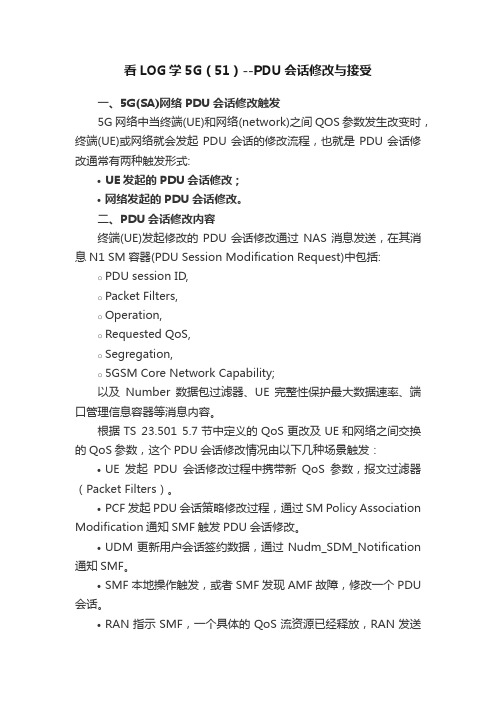
看LOG学5G(51)--PDU会话修改与接受一、5G(SA)网络PDU会话修改触发5G网络中当终端(UE)和网络(network)之间QOS参数发生改变时,终端(UE)或网络就会发起PDU会话的修改流程,也就是PDU会话修改通常有两种触发形式:•UE发起的PDU会话修改;•网络发起的PDU会话修改。
二、PDU会话修改内容终端(UE)发起修改的PDU会话修改通过NAS消息发送,在其消息N1 SM容器(PDU Session Modification Request)中包括:o PDU session ID,o Packet Filters,o Operation,o Requested QoS,o Segregation,o5GSM Core Network Capability;以及Number数据包过滤器、UE 完整性保护最大数据速率、端口管理信息容器等消息内容。
根据TS 23.501 5.7节中定义的QoS更改及UE和网络之间交换的QoS参数,这个PDU会话修改情况由以下几种场景触发:•UE发起PDU会话修改过程中携带新QoS参数,报文过滤器(Packet Filters)。
•PCF发起PDU会话策略修改过程,通过SM Policy Association Modification通知SMF触发PDU会话修改。
•UDM更新用户会话签约数据,通过Nudm_SDM_Notification 通知SMF。
•SMF本地操作触发,或者SMF发现AMF故障,修改一个PDU 会话。
•RAN指示SMF,一个具体的QoS流资源已经释放,RAN发送N2消息到AMF,包括QFI,用户位置信息以及QoS流释放指示。
三、网络侧发起PDU会话修改消息解析5G网络中无论是终端还是网络发出的PDU会话请求,正常情况下对方均会按照参数进行修改,完成后回送会话修改完成消息。
图1.无线网络中的PDU会话修改3.1 PDU会话修改命令NrnasOtaMsgInterface-MSG0> 08 000010001> 07 00000111 ..enNrnasOtaMsgId:nRSM-OTA-MSG-PDU-SESSION-MOD-CMD (1800)(NR NAS OTA消息:PDU会话修改命令)2> 01 00000001 ..ucUpDown:0x1 (1)3> 04 00000100 ..ucVersion:0x4 (4)7> 00 00000000 ..ulLengthASN:0x158 (344)..struMsgChoice....struNRNAS-SM-MSG-STRU(NR NAS SM消息结构)11> 00 00000000 ......ulNasMsgSize:0x14c (332)12> 2E 00101110 ......extended-protocol-discriminator:0x2e (46)13> 05 00000101 ......pdu-session-identity:pDU-session-identity-value-5 (5)(PDU会话ID=5)14> 00 00000000 ......procedure-transaction-identity:0x0 (0)......msg-body15> CB 11001011 T........pDU-session-modification-command(PDU会话修改命令)18> 70 01110000 L..........authorized-qos-rules(QOS认证规则)............qos-rule-list..............Qos-rule19> 02 00000010 ................qoS-rule-identifier:0x2 (2)(QOS规则ID=2)21> 35 00110101 L................qos-rule-info22> 22 001----- ..................rule-operation-code:create-new-QoS-rule (1)---0---- ..................dqr:the-QoS-rule-is-not-the-default-QoS-rule (0)----0010 ..................number-of-packet-filters:0x2 (2)(数据包过滤器)..................create-new-QoS-rule-list....................create-new-QoS-rule......................Create-new-QoS-rule23> 20 00------ ........................spare:0x0 (0)--10---- ........................packet-filter-direction:uplink-only (2)(数据包过滤器方向-仅上行)----0000 ........................packet-filter-identifier:0x0 (0)(数据包过滤器ID=0)24> 17 00010111 L........................packet-filter-contents..........................packet-filter-contents-component............................Packet-filter-contents-component..............................pf-component25> 21 00100001 T................................iPv6-remote-address-prefix (远端IPV6地址字首)......41> 03 00000011 ...............................ipv6-addr:24 09 80 10 50 02 00 18 00 00 00 00 00 07 00 0342> 80 10000000 ..................................prefix-length:0x80 (128)(字首长度=128)............................Packet-filter-contents-component..............................pf-component43> 30 00110000 T................................protocol-identifier-Next-header44> 11 00010001 ..................................protocol-identifier:0x11 (17)............................Packet-filter-contents-component..............................pf-component45> 50 01010000 T .............................single-remote-port(单一远程端口)46> 71 0111000147> 9D 10011101 ..................................remote-port:0x719d (29085)(远端端口=29085)......................Create-new-QoS-rule48> 11 00------ ........................spare:0x0 (0)--01---- ........................packet-filter-direction:downlink-only (1)((数据包过滤器方向-仅下行)----0001 ........................packet-filter-identifier:0x1 (1)......128> 18 00011000 ..................................local-port:0x7918 (31000)129> BD 10111101 ..................qoS-rule-precedence:0xbd (189)130> 02 0------- ..................spare:0x0 (0)-0------ ..................segregation:not-requested (0)--000010 ..................qoS-flow-identifier:0x2 (2)133> B2 10110010 L..........mapped-EPS-bearer-contexts-list1(EPS承载与报文映射)................eps-bearer-identity134> 70 0111---- ..................epsId:0x7 (7) (EPS ID=7)----0000 ..................spare:0x0 (0)137> 52 01------ ..................operation-code:create-new-EPS-bearer (1)(新增EPS承载)--0----- ..................spare:0x0 (0)---1---- ..................e-value:0x1 (1)----0010 ..................number-of-EPS-parameters:0x2 (2)(EPS 参数列表)138> 01 00000001 ......................eps-parameter-identity:mapped-EPS-QoS-parameters (1)139> 05 00000101 L......................eps-parameter-content(EPS参数内容)........................mapped-EPS-QoS-parameters(EPS参数映射)140> 01 00000001 ..........................qCI:0x1 (1)(QCI=1)141> 35 00110101 ..........................maximum-bit-rate-for-uplink:0x35 (53)(上行最大速率53)142> 35 00110101 ..........................maximum-bit-rate-for-downlink:0x35 (53)(下行最大速率53)143> 35 00110101 ..........................guaranteed-bit-rate-for-uplink:0x35 (53)(上行保证速率53)144> 35 00110101 ..........................guaranteed-bit-rate-for-downlink:0x35 (53)(下行保证速率53)....................EPS-parameters-list(EPS参数列表)145> 03 00000011 ................eps-parameter-identity:traffic-flow-template (3)(EPS参数ID:TFT 3)146> A5 10100101 L......................eps-parameter-content........................traffic-flow-template147> 24 001----- ..........................tft-operation-code:create-new-TFT (1)(TFT编码:新增TFT1)---0---- ..........................e-bit:parameters-list-is-not-included (0)----0100 ..........................number-of-packet-filters:0x4 (4)..........................packet-filter-list2............................Create-packet-filter148> 20 00------ ..............................spare:0x0 (0)--10---- ..............................packet-filter-direction:uplink-only (2)----0000 ..............................packet-filter-id:0x0 (0)149> 00 00000000 ..............................packet-filter-evaluation-precedence:0x0 (0)150> 26 00100110 L..............................packet-filter-contents................................packet-filter-contents-component..................................Packet-filter-contents-component....................................pf-component......208> 03 00000011 ........................................ipv6-addr:24 09 80 10 50 02 00 18 00 00 00 00 00 07 00 03 ......224> FF 11111111 ........................................ipv6-addr-mask:FF FF FF FF FF FF FF FF FF FF FF FF FF FF FFFF ..................................Packet-filter-contents-component ....................................pf-component225> 30 00110000 T......................................protocol-identifier-Next-header226> 11 00010001 ........................................protocol-identifier:0x11 (17)..................................Packet-filter-contents-component....................................pf-component227> 40 01000000 T......................................single-local-port228> 79 01111001229> 19 00011001 ........................................local-port:0x7919 (31001)............................Create-packet-filter230> 22 00------ ..............................spare:0x0 (0)--10---- ..............................packet-filter-direction:uplink-only (2)----0010 ..............................packet-filter-id:0x2 (2)231> 02 00000010 ..............................packet-filter-evaluation-precedence:0x2 (2)232> 26 00100110 L..............................packet-filter-contents................................packet-filter-contents-component..................................Packet-filter-contents-component....................................pf-component233> 20 00100000 T......................................iPv6-remote-address......318> 07 00000111 ......................parameter-identifier:pi-EPS-bearer-identity (7)319> 01 00000001 L......................qos-flow(QoS流)........................ePS-bearer-identity320> 70 0111---- ..........................epsId:0x7 (7)(EPS ID=7) ----0000 ..........................spare:0x0 (0)....................Parameters-container321> 01 00000001 ......................parameter-identifier:pi-5qi (1)(参数ID:PI=5QI)322> 01 00000001 L......................qos-flow323> 01 00000001 ........................parameters-5qi:0x1 (1)(5QI参数)....................Parameters-container324> 02 00000010 ......................parameter-identifier:pi-GFBR-uplink (2)(PI:GFBR2上行)325> 03 00000011 L......................qos-flow........................gFBR-uplink(上行GFBR)326> 01 00000001 ..........................unit:value-is-incremented-in-multiples-of-1-Kbps (1)(多线程以1Kbps为单位增加)327> 00 00000000328> 35 00110101 ..........................value:0x35 (53)....................Parameters-container329> 03 00000011 ......................parameter-identifier:pi-GFBR-downlink (3)330> 03 00000011 L......................qos-flow........................gFBR-downlink331> 01 00000001 ..........................unit:value-is-incremented-in-multiples-of-1-Kbps (1)333> 35 00110101 ..........................value:0x35 (53)....................Parameters-container334> 04 00000100 ......................parameter-identifier:pi-MFBR-uplink (4)335> 03 00000011 L......................qos-flow........................mFBR-uplink(mFBR上行)336> 01 00000001 ..........................unit:value-is-incremented-in-multiples-of-1-Kbps (1)(多线程以1Kbps为单位增加)337> 00 00000000338> 35 00110101 ..........................value:0x35 (53)....................Parameters-container339> 05 00000101 ......................parameter-identifier:pi-MFBR-downlink (5)340> 03 00000011 L......................qos-flow........................mFBR-downlink341> 01 00000001 ..........................unit:value-is-incremented-in-multiples-of-1-Kbps (1)343> 35 00110101 ..........................value:0x35 (53)3.2 PDU会话修改完成NrnasOtaMsgInterface-MSG0> 09 000010011> 07 00000111 ..enNrnasOtaMsgId:nRSM-OTA-MSG-PDU-SESSION-MOD-CMPL (1801)(NR NAS消息:PDU会话修改完成)2> 00 00000000 ..ucUpDown:0x0 (0)3> 04 00000100 ..ucVersion:0x4 (4).....7> 00 00000000 ..ulLengthASN:0x10 (16)..struMsgChoice....struNRNAS-SM-MSG-STRU (NR NAS SM消息结构)8> 04 000001009> 00 0000000010> 00 0000000011> 00 00000000 ......ulNasMsgSize:0x4 (4)12> 2E 00101110 ......extended-protocol-discriminator:0x2e (46)13> 05 00000101 ......pdu-session-identity:pDU-session-identity-value-5 (5)(PDU会话ID=5)14> 00 00000000 ......procedure-transaction-identity:0x0 (0)......msg-body15> CC 11001100 T........pDU-session-modification-complete(PDU会话修改完成)。
Infineon SGBT (HSTCU) Active Probe User Manual V2.
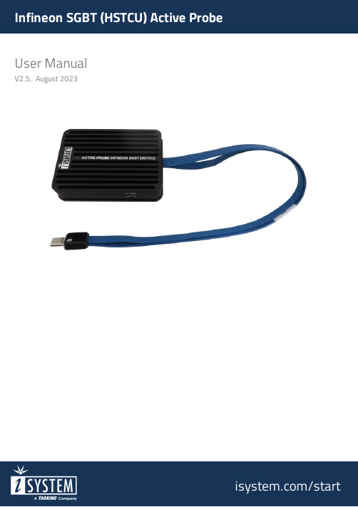
User ManualV2.5, August 2023/startGeneral safety instructionsPlease read the following safety precautions carefully before putting this device to use to avoid any personal injuries, damage to the instrument, or to the target system. Use this instrument only for its intended purpose as specified by this manual to prevent potential hazards.Use included power cord and power supplyThe enclosed power supply has been approved for use by iSYSTEM. Please contact iSYSTEM if you need to consider an alternative power.Use grounding wirePrior to applying power to either the BlueBox or the target, connect the device and the target system together with the included grounding wire. This is to avoid potential damage caused by any voltage difference between the device and the target system.Use proper overvoltage protectionEnsure proper protection to avoid exposing the BlueBox device or the operator to overvoltage surges (e.g. caused by thunderstorm, mains power).Do not operate without coverDo not operate the device with cover removed.Avoid circuit and wire exposureDo not touch exposed components or wires when the device is powered.Do not operate with suspected damageIf you suspect damage may have occurred, the BlueBox device must be inspected by qualified service personnel before further operation.Do not operate the device outside its rated supply voltage or environmental rangeConsult with iSYSTEM before using equipment outside of the parameters provided in this manual.This symbol is used within the manual to highlight further safety notices.ContentsPackage content (4)Specifications (5)Operation (6)mDIO Cable (8)HSTCU (USB-C) to Samtec22 Converter (9)HSTCU (USB-C) to DAP10 1.27 Converter (11)Hardware Setup and Configuration (13)Accessories (14)User Notes (15)Infineon SGBT (HSTCU) Active Probe enables debugging, tracing and testing of all Infineon AURIXT™ TC2xx, TC3xx (2nd generation), TC4xx (3rd generation) microcontrollers. It supports the DAP and Aurora GigaBit Trace (AGBT/SGBT) interface via USB-C connector. Its small and compact hardware size allows for connecting to a target microcontroller in a confined space as far as 10 m away. The Active Probe supports up to 1 parallel AGBT lanes, running at a maximum bitrate of 5Gbps.The Infineon SGBT (HSTCU) Active Probe kit is delivered with the following components: Infineon SGBT (HSTCU)Active Probe1m FNet CableOrdering code: IC57166Ordering code: BB-FNET-100Blue colored signals are trace signals.Signal direction definition:O – Output from the Active Probe to the target microcontroller I – Input to the Active Probe from the target microcontrollerB – mDIO port marked as TRIG on the housingmDIO port provides two digital signals, which can interact with the embedded target. Each can be configured either for input or output operation.mDIO port on the Active ProbeC – The indicator light provides the status of the Active Probe as follows:Permanently green – Powered on and ready to use.Blinking green – Establishing connection with the BlueBox.Blinking blue – Reprogramming SPLASH.Permanently magenta – Golden image loaded and ready to use.D – FNet connector, that connects the Active Probe to the iC5700 BlueBox. The FNet cable is delivered with the Active Probe.When powering on the system, switch the iC5700 on before powering on the target. When powering down the system, power off the target before powering off the iC5700!UseConsult with iSYSTEM before attempting to use any other accessory.Ordering code BB-AP-MDIO-20mDIO Cable is used to connect the Active Probe mDIO port with the signals around the debugged microcontroller, which can then be either read or controlled by the debugger. For example, the debugger can periodically service an external watchdog through the mDIO output or just read and record an external signal through the mDIO input. It must be ordered separately. Length of the cable is 20 cm.Ordering code IAHSTCU-SAM22The converter is used to connect the Infineon SGBT (HSTCU) Active Probe with the USB-C connector to a target featuring Samtec 22-pin ERF8 debug connector. The 22-pin converter must be ordered separately.Connecting USB-C converter to the Active ProbeUsed physical USB-C type connector doesn’t feature the USB interface as someone could presume (there is no way to incorrectly insert it), but rather the Infineon AGBT (Aurora GigaBit Trace) interface whose signals are connected to the connector in a way that USB-C connector orientation matters.When attaching this converter to the Active Probe, make sure itsBBlue colored signals are trace signals.Blue colored signals are trace signals.*Current TriCore devices feature only one AGBT line while the Active Probe hardware is ready for future devices with more AGBT lines.Ordering code IAHSTCU-DAP10This converter is used to connect Infineon SGBT (HSTCU) Active Probe (Ordering code: IC57166) to the target via DAP connector. It must be ordered separately.When attaching this converter to the Active Probe, make sure itsBSignal Direction is described from the BlueBox perspective.When connecting the BlueBox to a target for the first time, doubleadapterfailure.For detailed visual presentation of the hardware setup and configuration, refer tostarted tutorial1. Connect the power supply cable. BlueBox should be switched off.2. First connect via USB. Later you can configure TCP/IP connection to work remotely.3. Connect the Grounding wire to the BlueBox and the Target.IfBlueBox and the Target can exceed well over 1000V even before any of the devices arepoweredleading to the possible destruction of electronic components.4. Connect FNet cable of Active Probe to the BlueBlux FNet port.Although it looks similar to the HDMI interface, theHDMI or any HDMI accessoriesConnecting iSYSTEM hardware to HDMI accessories will damage the hardware and willrender the iSYSTEM hardware warranty void.5. Power ON the hardware in the following order:a.BlueBoxb.Target6. Install winIDEA and create a new workspace.7. Configure Debug channel modes via Hardware / CPU Options / SoC.For troubleshooting refer to Knowledge Base - .More general settings are described in winIDEA Help.The functionality can be extended through the use of various modules from IOM6 product line which enable capabilities from parallel debugging of multiple targets, monitoring of network traffic and monitoring and manipulation of analog and digital signals.More information about our products onThis page is intentionally left blank.Visit our website for:·Support - /support ·Tutorials - /getting-started ·Knowledge Base - 。