PDA-1301D-XFA中文资料
PDA TR-40 气体除菌过滤(中文版)

仅限 Pall China 内部使用
2
翻译:董巍/Vivien Dong
气体除菌过滤
技术报告第40号 气体除菌过滤 增补
第58期 编号 S-1 2005年1/2月
注射剂协会 2005
中文稿翻译:董巍/Vivien Dong Pall China, Life Sciences
Jerold Martin, Pall Corporation 颇尔公司
Leesa McBurnie, Meissner Filtration Products, Inc. 梅斯内尔
Theodore H. Meltzer, Ph.D., Capitola Consulting Co. 凯比托拉
Didier Meyer, la Calhene, France 法国
3.1 筛分法/机械截留 ...................................................................................................6 3.2 小微粒的截留.........................................................................................................7
Maik W. Jornitz, Sartorius Corporation 赛多利斯
Stephen Langille, Ph.D., FDA 注射剂协会
Richard V. Levy, Ph.D., PAREXEL Consulting 巴勒克塞尔
PT1301中文技术资料-诚芯微科技

Tape and Reel 3000units Tape and Reel 1000 units Tape and Reel 3000 units
1301 PT1301 xxxxxX PT1301 xxxxxX
Assembly Factory Code Lot Number
(1) 3.3V, 100mA MP3
PT1301_DS Rev CH_3.5
Page 9
-2 --0.22 -1.225 400 85 -1 ----0.4
0.80 -0.01 14 0.24 56 1.25 500 94 0.3 1.5 4.4 2.45 1.25 0.14 0.8 50
1.05 6 1 25 0.7 -1.275 600 -1.1 2 8.5 8.5 5 -1.2
V V A A mA A V KHz %
DIMENSION( in Inch ) MIN 0.055 0.014 0.094 0.016 0.031 0.173 0.055 0.014 0.181 0.067 0.063 0.017 MAX 0.063 0.020 0.102 0.021 0.167
éóèéìèéìí éóèíì
éóèéìèéìí éóèíì
PT1301_DS Rev CH_3.5
Page 5
PT1301
DC/DC
(3) (3.1) Vout=3.3V (3.2) Vout=5.0V
1)
1 : (Vout) 100pF 0.1uF 3) 1 R2 VDD R R FB FB R1 R2 R1 R2 PCB FB FB LX EXT ( I=1.25V/R2 ) , Vin GND GND R1 PCB PCB
PDA101系列产品说明书

SpecificationPDA101SFor TV lounges etc.Specification as PDA101L but the microphone is replaced by a SCART lead30metres of 0.5mm 2 loop cable supplied.PDA101CFor ticket countersSpecification as PDA101L but loop cable replaced by easily installed TxBI loop padP D A 101M m i c r o p h o n e supplied.VariantsInputs Two 3.5mm Mono Jack socket MicrophoneImpedance 1 K WSensitivity -92 dB to -43 dB Phantom 2.5 V on tip, max current 0.25mA Line Impedance 47 K WSensitivity -30 dB to -12 dB Performance Dynamic range >75 dB Noise <-72 dBInput level controlSwitchable between mic and line for each inputMicrophone adjustable - ∞ to –56dB Line adjustableBandwidth40 Hz to 15 KHz, 0 dB line input -52 dB mic input40 Hz to 8 KHz, -24 dB line input -77 dB mic input Output Drive current Max 3.12 A PeakMax 1.42 A RMS 1 KHzLoop coverage50m 2 max. - must use 0.5mm 2 cable or TxBI counter loop padLoop impedance 0.2W to 1.2W PowerrequirementsMains voltage 230V AC ± 20% Consumption < 20VA2m mains lead and fused plug providedFusesPlug top 3AInternal mains fuse 250mA 20mm (HRC) DimensionsWidth 110mm Height 52mm Length 133mm Weight 785gPacked weight 1640gNo responsibility can be accepted by themanufacturers or distributors of this product for any misinterpretation of an instruction or guidance note or for the compliance of the system as a whole. These instructions are general and cannot be considered to cover every aspect of an installation. The manufacturer’s policy is one of continuous improvement and we reserve the right to make changes to product specifications at our discretion and without prior notice. E&OE.FeaturesTechnical Description50m 2 maximum coverage Wall mountable case2 x 3.5 mm inputs switchable between line and mic as requiredAutomatic compressor / expander Input adjustableLoop current adjustable to suit room conditionsUses up to 30 metres of 0.5mm 2 cable only (supplied)See page 8 for features of variantsThe PDA101 is a true constant current induction loop amplifier and is designed to cover up to an absolute maximum of 50m² (7.07m x 7.07m).A gain of 52 dB is applied to the microphone signal and a gain of 0dB to the line input. The signals are mixed using the front panel controls and then fed into the compander. This ensures that very low level or high level sources can be used without pre-amplification or attenuation. The compander maintains the output level within a 45dB window.Operation Instruction ManualPDA101L & VariantsAudio frequency induction loop ampilifiersAC power operationFor normal AC operation, plug the AC power supply cord in a wall outlet of 230 V specified voltage. The unit complies with BS415.AC power cordThe power cord supplied with the unit has a moulded plug. If it is necessary to remove the plug at any time, it must be replaced with a plug top meeting BS1363A, or equivalent, fitted with a 3 Amp fuse. The wires in the mains lead supplied with the unit are coloured in accordance with the following code. Green and Yellow Earth Blue Neutral BrownLiveAs the colours of the wires in the mains lead of this unit may not correspond with the coloured markings identifying the terminals in your plug, please connect as follows. Wire Plug terminalGreen & Yellow‘E’ mark‘EARTH’ symbol mark ‘GREEN’ mark‘GREEN AND YELLOW’ markBlue‘N’ mark‘BLACK’ mark ‘BLUE’ mark Brown‘L’ mark ‘RED’ mark ‘BROWN’ markCautionTo prevent electric shock do not remove the coverUpon receipt of the amplifier shipment, please inspect for any damage incurred in transit. If damage is found, please notify your local representative and the transport company immediately. State date, nature of damage and whether any damage was noticed on the shipping container prior to unpacking. Please give the waybill number of the shipping order.The unit should not be placed in areas; 1.with poor ventilation2.exposed to direct sunlight3.with high ambient temperature or adjacentto heat generating equipment 4.with high humidity or dust levels 5.susceptible to vibrationUnpackingIntentionally Blank Intentionally BlankLoop patternsA loop pattern laid on the floor is a low cost method to reduce over-spill by providing more even field strength compared to the usual single turn of cable laid around the room’s perimeter. The basic pattern looks like the diagram below:Large areas and multiple roomsUse several loop patterns, each pattern must be connected to a separate loop amplifier. When laying out patterns, ensure each is 90 degrees out of phase with its neighbours as per the following diagrams which show a two storey building:Note. For a two storey building the same loop position on different floors is also 90 degrees out of phase.Non-rectangular roomsLayout as per a basic pattern and step backthe prongs to the shape of the room.Each pattern should be considered as a many pronged fork. The pattern should be spaced approx. 2m from nearest wall / next pattern, prongs of the fork should be spaced approx. 2m apart and should be approx. 2m wide, prongs should extend to approx. 3/4m of base of fork.Assume the cable is being run around the edge of a room for cable diameter calculations, as the pattern restricts the amount of power which can be fed into the loop. The large black arrow shows clockwise direction of loop. Break into pattern at any point to connect PDA unit. Loop patternsInstallation Input connectionsTwo input connectors are standard 3.5mmmono jack sockets. Both are mic or lineselectable dependant upon the DIP switchpositions, use the following chart or see theback of the unit which has the switch positionsnext to the switches.Phantom power is supplied - 2.5V, 0.25mAmaximum.Read this manual thoroughly before startinginstallation, the following procedure should beused.1.Install the loop (see page 6)2.Before connecting a loop to the amplifieruse, a multimeter to check the loop is notshorted to ground at any point, (it will almostcertainly damage the amplifier if it is).Remove approximately 6mm of the outerinsulation from the cable. Connect the loopcable to the amplifier by inserting a terminalscrewdriver into the small rectangular holeabove the cable insertion hole, this will openthe insertion hole and allow the cable to bepushed into the connector. Remove theterminal screwdriver and the connector willclose gripping the cable. Ensure theconnector is gripping the conductor in thecable and not the insulation.3.Connect music or speech input signal to theamplifier. The peak line level of this signalshould be approximately 1V.4.Set the DIP switches as required.5.Ensure input levels controls and drivecontrol are fully anti-clockwise.6.Connect mains lead to the amplifier andensure the power LED (green) lights.7.Increase the input level controls until the red‘limit’ LED is just flashing. If you are usingboth inputs the level controls act as a simplemixer.8.Adjust the drive control until the red clip LEDjust lights during periods of high signal level(when the limit led just lights).ing an induction loop receiver (eg SigNETRxti2 or a field strength meter), listen to thesignal inside the loop. It is also advisable tocheck the system with a field strength meter.Please note that the orientation of the fieldstrength meter may influence the reading.Mains HumBackground hum can sometimes be heardwhen testing an installation especailly whentesting with a induction loop receiver. This isnot caused by the loop system and will NOTnormally be heard by hearing aid users, due tobuilt in filtering in most hearing aids. Thesource of mains hum is most likely to be (50Hz) mains wiring, particularly in old buildingswhere Live and Neutral cables may takedifferent routes, thus creating an inductionloop radiating at 50Hz. If the client complainsof mains hum simply switch off the amplifier toSwitch Off On1 Line Microphone2 Phantom Off Phantom ON3 Line Microphone4 Phantom Off Phantom ONOutput connectionsLoop outputThe output is via two Screwless vertical PCB terminals. Connection is made by way of tails. To allow cables to be inserted, slide a terminal screwdriver into the rectangular hole directly above the cable entry hole to be used, when cable has been inserted remove the screwdriver which allows the connector to close and grip the conductor.WARNING: The PDA amplifiers are capable of producing short term peaks of twice their rated current.The PDA101 can be wall mounted, using No 8 japanned woodscrews (provided) on 100 mm centres vertical or 45 mm centres horizontal, using the holes marked on the diagram below. Care must be taken when attaching unit to screw heads to ensure that screw heads do not damage the printed circuit board.Wall mountingLoop cablesCable selectionOnly 0.5mm 2 cable, as supplied, should be used. If other cable types are used it will be necessary to adjust the drive current as appropriate.Use of a tri-rated cable is recommended. This is cable with a tougher than usual jacket, the reason being; damage will occur to the amplifier if at any point the loop is grounded. Loop cable should ideally be laid at floor level but in certain circumstances this may not be possible. Any large amounts of metal (eg steel meshed reinforced concrete floors) will absorb some of the signal strength, in this case the cable may have to be mounted in the walls. Aluminium (suspended ceilings) being para-magnetic should also be avoided, mounting a loop above an aluminium suspended ceiling will probably result in almost no coverage, turning up the output of an amplifier would just make matters worse as it will just stress the output stage (and minutely warm the aluminium) resulting in a definite shortening of the life-span of the amplifier.Speaker positioningIf a speaker is placed near or beside a loop cable the cross-over in the speaker may pick up the loop signal, so try to keep speakers and loop cables as far apart as possible. Normally this does not show up in use because loop and speaker have the same programme material, only where the loop has a different signal to the speakers (e.g. stage talk back systems)will this become an issue.Feeder CablesWhen connecting an amplifier to a loop some distance away use a heavy gauge twisted pair (2.5mm 2). This will have a negligible impedance, as such the amplifier will not drive against it and the power will be fed into the loop where it can do useful work.Test loopsWe always recommend the laying of a test loop, there is no such thing as a standard installation and sometimes only a test loop will uncover problematic areas.FeedbackLong lengths of unbalanced signal cable may cause feedback when placed inside the loop. Keep connecting audio leads as short as pos-sible.Problems may occur when using standard dynamic microphones. The coil inside may act as a receiver and cause feedback. It is advisable to use condenser microphones. These may require phantom powering, available on both microphone inputs.Other sources of feedback are coils in other equipment that is linked to the induction loop system, for example guitar pickups.Loop cable classA loop cable is classed as a 2A cable under IEEE 16th Edition wiring regulations. As such it must be sited a minimum of 600mm away from telephone, mains and control cables.Loop cables。
PDA TR 版 中文
液体的除菌过滤PDA第26份技术报告(2008年修订本)制药科学与技术的PDA期刊增刊2008年第62卷,第S-5号1.0引言除菌过滤是从液体流中去除微生物*而对产品质量没有负面影响的过程。
(1-4)这份技术报告的目的是提供系统的方法,用于选择和验证液体除菌过滤应用的最适当过滤器。
PDA的第26份原始技术报告发表于1998年,标题为液体的除菌过滤,其中描述了一代制药科学家和工程师对除菌过滤的使用和验证。
由于过滤技术的加强以及制药行业近期产生了其他的法规要求,因而对原始报告进行了修改。
修订本涉及到了法规文件、标准以及科学出版物,其中包含更多的细节和支持性数据。
在20世纪60年代膜过滤器进入市场,当时认为0.45µm级别的膜为“除菌级”过滤器且成功应用于注射剂的除菌过滤。
使用serratia marcescens作为标准菌对这些过滤器进行确认,确认用于水质量测试的膜。
然而在1960年发布的论文中,美国FDA的Frances Bowman博士发现0.45µm的“除菌过滤的”培养基可受到一种生物的污染,在每平方厘米104-106以上的挑战水平下少量的这种生物可反复穿透0.45µm级别的膜。
(5)ASTM F838也由此产生,这是一种标准测试法,用于评估除菌级别的膜过滤器。
(6)在第6.4部分中对挑战生物进行了讨论。
1.1目的/ 适用范围工作组的主要目标是开发一份有关除菌过滤的科学的技术报告。
报告不会对区域的法规要求进行过多的描述,但是提供了最新的科学建议以供业内人士及制定除菌过滤政策的人员使用。
这份报告是一份指南性文件,其目的不是确立强制的除菌过滤标准。
报告中提出的概念与一些工艺有关,在这些工艺中除菌过滤器的性能是不可缺少的,而且这些概念不能通用于所有过滤工艺(例如,早期过滤或常规生物负载)。
这些概念包括但不限于细胞培养基、缓冲液、无菌工艺中的中间体暂存区、集中和最终无菌灌装。
广东金刚玻璃PDA全钢防火隔断(幕墙)

A级不燃材料,B1级难燃材料,B2级可燃材料,也称阻燃材料,B3级易燃材料
相关专业术语
中国与欧洲防火规范中关于镶玻璃防火构件的防火性能对照表
防火玻璃防火性能 防火框架防火性能
防火构件防火时限
中国防火规 范
欧洲防火规 范
A
B C — — — 0.5
1
1.5
2
小时 小时 小时 小时
EI EW E EI EW E 30 60 90 120 分钟 分钟 分钟 分钟
ISO-hermetic 60N
47
60
cross section drain guiding bush Intersection cover clamp isolator bush system • ensure straight and accurate srew alignment • correct Pressure pressure and connectting plate
What are the differences?
Integrity only E30,E60,E90,E120 (30/0,60/0,90/0,120/0) 耐火完整性:(相当于国标中规定的C类)
防火构件在规的时间内(即30分钟、60分钟、90分钟或120分钟)阻 止火焰、烟雾和高温产生的气体向背火面一侧蔓延
Integrity & radiated heat control EW30, EW60 耐火完整性和防热辐射性:(相当于国标中规定的B类)
防火构件在达到耐火完整性的同时,要求距背火面1 米处,临界辐射热 量不超过15kw/m2
Integrity & Insulation EI30, EI60, EI90, EI120 (30/30,60/60,90/90,120/120) 耐火完整性和隔热性:(相当于国标中规定的A类)
PDA-1301A-VX资料
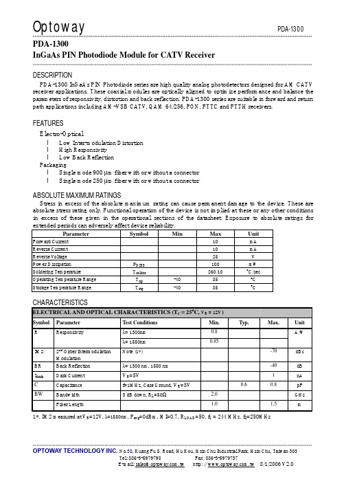
**************************************************************************************************************************************************************** PDA-1300InGaAs PIN Photodiode Module for CATV Receiver**************************************************************************************************************************************************************** DESCRIPTIONPDA-1300 InGaAs PIN Photodiode series are high quality analog photodetectors designed for AM CA TV receiver applications. These coaxial modules are optically aligned to optimize performance and balance the parameters of responsivity, distortion and back reflection. PDA-1300 series are suitable in forward and return path applications including AM-VSB CA TV, QAM 64/256, PON, FTTC and FTTH receivers. FEATURESElectro-Opticall Low Inter-modulation Distortionl High Responsivityl Low Back ReflectionPackagingl Single mode 900 µm fiber with or without a connectorl Single mode 250 µm fiber with or without a connectorABSOLUTE MAXIMUM RATINGSStress in excess of the absolute maximum rating can cause permanent damage to the device. These are absolute stress rating only. Functional operation of the device is not implied at these or any other conditions in excess of these given in the operational sections of the datasheet. Exposure to absolute ratings for extended periods can adversely affect device reliability.Parameter Symbol Min Max UnitForward Current 10 mAReverse Current 10 mAReverse V oltage 25 VPower Dissipation P DISS100 mWSoldering Temperature T solder260/10 o C/secOperating Temperature Range T op-40 85 o CStorage Temperature Range T stg-40 85 o CCHARACTERISTICSELECTRICAL AND OPTICAL CHARACTERISTICS (T C = 25ºC, V R = 12V)Symbol Parameter Test Conditions Min. Typ. Max. Unitλ= 1300nm 0.8A/WR Responsivityλ= 1550nm 0.85Note (1*) -70 dBcIM2 2nd Order IntermodulationModulationBR Back Reflection λ= 1300 nm, 1550 nm -40 dBI dark Dark Current V R=5V 1 nAC Capacitance f=1MHz, Case Ground, V R=5V0.6 0.8 pFBW Bandwidth 3 dB down, R L=50Ω 2.0 GHz Fiber Length 1.0 1.5 m1*. IM2 measured at V R=12V, λ=1550nm, P avg=0dBm, MI=0.7, R LOAD=50, f1 = 244 MHz, f2=250MHz**************************************************************************************************************************************************************** PRECAUTIONS for USEESD protection is imperative. Use of grounding straps, anti-static mats, and other ESD protective equipment is recommended when handling or testing an InGaAs PIN or any other junction photodiodes.Fiber pigtails should be handled with less than 10N pull and with a bending radius greater than 30 mm. MECHANICAL DIMENSION (mm) and PIN ASSIGNMENTNote: 1.Specifications subject to change without notice.2. Other PIN assignment is available upon request.ORDER INFORMATIONPart No.: P D A − 1 3 0 □□。
PDA参数

PDA参数产品特性■内置一维、二维条码扫描■内置GPS定位模块■内置CCD摄像模块■内置低频(134.2KHz)、高频、超高频RFID读写模块■支持蓝牙、WiFi、GSM/GPRS通讯■支持CISCO CCX2/3无线安全协议■ 3.5寸QVGA彩色触摸屏■集成测温、测振传感器,可用于工业巡检/点检■Win CE 5.0操作系统,支持多语言■工业等级封装,IP54,1.2米防跌落■128M内存,128M Flash,SD卡槽■支持超低温工作环境■内置完整TELNET客户端■支持中文手写输入和9键智能中文输入法■支持Microsft .net COMPACT framework 3.5■支持A-GPS,快速捕获定位卫星信号■完整的软件开发模板,大大缩短软件开发时间■具有良好的性价比产品指标实时移动采集和数据管理,实现真正的即时商业决策i60是一款轻便耐用的移动数据电脑,对于需要在整个企业都部署高质量的无线数据采集解决方案,以满足高强度扫描环境需要的企业,i60无疑是最理想的选择,在零售行业,物流行业,生产领域中广范应用良好的性能和灵活性i60配备了多种可选功能。
其中包括激光条码扫描,GPRS无线通讯,无线局域网,蓝牙等客户定制选择可靠性高,可在恶劣环境中使用i60坚固耐用的工业设计以及符合IP54标准的密封使产品具有很好的防尘防潮效果,并能够在极端环境条件下使用,确保产品能够连续正常的工作。
无论在室内还是在室外,在大范围温度变化的情况下,i60都具有很好的抗震能力能承受从1.2米高度多次跌落到水泥地面的冲击,从而降低了设备的维护成本。
支持多种移动软件,包括数据库管理软件移动设备管理软件,通信安全性软件。
物理特性尺寸:190x80x25mm重量:400g(带标准电池)环境工作温度-15℃ - +50℃\储存温度-20℃ - +60℃相对湿度:5%-95%(无凝露)防水防尘等级:IP54跌落承受规格:可承受1.2m高处多次跌落到水泥地面的考验滚动:室温下,可承受500次0.5米滚动(1000次跌落)电源标准电池: 3.7V 2800mAh/3200mAh锂离子电池内部备用电池:17mAh操作系统Windows CE 5.0 操作系统(多语言)微处理器SAMSUNG 400 MHz CPU存储器Flash 64/128MB\RAM 64/128MBSD插槽最大支持1GB FLASH RAM显示屏3.5寸QVGA (240*320像素)64K色,透反射式TFT-LCD,LED 背光键盘25+1子母数字背光键盘柔软按键,支持手写输入音频支持双扬声器标准通信USB1.1主机和客户端 \ RS232接口内置无线通信选件蓝牙接口Class2 V1.1无线网符合IEEE802.11b/g标准(11Mb/S-54Mb/S)GSM/GPRS通信模块(900/1800/1900MHz)扫描系统内置激光扫描引擎 (可选配)WLAN 安全选件WPA,802.11i(WPA2),WEP,TKIP,TLS,TTLS, AES,PEAP,LEAP,MD5 充电器标准充电器 5V 3.0A配件USB数据线车载充电线Serial/USB Charge Cradle 1-Slot/2-Slot/4-Slot皮革背包屏幕保护膜认证UL 60950 and UL 1604CCC, TUV, CE mark,CCC。
PT1301

特点
z 低静态(开关关断状态)工作电流:17μA z 低启动输入电压: 1V z 高供电能力:由一节碱性电池提供 3.3V 100mA z 关断状态零工作电流
z 高效率: 90% z 固定开关频率: 500KHz z 可选择内部或外部功率管开关 z 封装形式: SOT-26,SOT-89-5
应用
PDA, DSC, LCD 显示屏, 射频标签, MP3, 便携设备, 无线设备, 等等。
PT1301
小尺寸、高效率、低电压的升压 DC/DC 转换器
概述
PT1301 是一款小尺寸、高效率、低电压、采用自适应电流模式的 PWM 控制封闭电路的升压 DC/DC 转换器。它包含误差放大器、斜率发生器、比较 器、功率开关和驱动器。PT1301 能在较宽的负载电流范围内稳定和高效的工作,并且不需要任何外部补偿电路。低于 1V 的低启动电压,使 PT1301 适合 1~4 节电池或锂电池供电 300mA 负载电流的应用。500KHz 的开关频率可缩小外部元件的尺寸。另外,17µA 的低静态电流,再加上高效率,可使电池使用 更长时间。输出电压由两个外部电阻设定。PT1301 内部含有 1.5A 功率开关,同时提供用于驱动外部功率器件(NMOS 或 NPN)的驱动器。
IL = 1mA VDD 引脚电压 CE Pin = 0V, VIN = 4.5V VIN = 6V VIN = CE= 3.3V, VFB = GND VIN = 1.5V, VOUT = 3.3V 闭环, VDD = 3.3V VDD = 3.3V
-2 --0.22 -1.225 425
0.80
极限值 -0.3~7.0V -0.3~7.0V
单位 V V
VIO IOUT
o IEXT r PTR c PTR iTopt MTstg
SP-DM13A-chinese

DM13A
单位 V V mA V
MHz mA
W
°C/W
°C °C
推荐工作参数
特性 电源电压
输出电压 输出电压
输出电流
输入电压
输入时钟频率 锁存信号(LAT)脉波宽度 数据信号(DCK)脉波宽度 串行输入数据(DAI) 的启动时间 串行输入数据(DAI) 的保持时间 锁存信号(LAT) 的启动时间 锁存信号(LAT) 的保持时间
Page 7
时序图
1. DCK-DAI, DAO
DM13A
2. DCK-LAT 3. LAT-OUT0
16 位 LED 恒流驱动芯片
Version:A.003
未经授权而径予重制、复制、使用或公开本文件,行为人得被追究侵权之相关民刑事责任 Unauthorized reproduction, duplication, use or disclosure of this document will be deemed as infringement.
⎯
单位 V uA V
±3
%
±6
%
±0.5 %/V
±4
4
6
6
mA
10
10
*1 输出电流差异(通道与通道间)定义为”任意 Iout - 平均 Iout” 与 ”平均 Iout”的比率。平均 Iout =(Imax+Imin)/2 *2 输出电流差异(芯片与芯片间) 定义为任选两芯片之最大输出电流与最小输出电流的落差范围。 *3 IO 除外。VDD = Nhomakorabea5.0V
最小值 3.3
1.0
⎯ 5 ⎯ ⎯ 0.8VDD 0.0 ⎯ 15 15 10 10 10 10
pda硬件使用说明

S3000 Series 中文使用说明书版权声明本文内所收录信息为说明产品目前状况,不具保证之意涵,包括但不限于任何暗示性或可销售性保证、或适用于某一特殊目的之保证;本公司保留调整有关产品功能、规格、保修信息及本文内容等的权利,恕不另行通知。
本文内包含有受版权法保护的独家专利信息,版权所有。
除版权法允许部分,否则未得深圳速比邻有限公司书面同意,不得影印、重制作、修改或翻译部份或全部内容。
控制本产品的程序部分亦受版权法保护,版权所有,不得侵犯。
Microsoft、ActiveSync、Pocket IE、Pocket Word、Windows、Windows 98、Windows Me、Windows NT、Windows 2000、Windows XP、Windows 标志、Windows CE标志或为注册商标,或为Microsoft Corporation 在美国及/或其它国家之注册商标。
Microsoft产品为Microsoft Licensing, Inc.授权之OEM产品,Microsoft Licensing, Inc.为Microsoft完全拥有。
本文内所提及的所有其它品牌名称及产品名称皆为各该公司合法的商标名、服务标志或注册商标。
在使用本产品之前,请认真阅读本说明书第一章包装确认 (4)第二章S3000简介 (5)第三章开始使用 (17)第四章其它选购配备的操作 (42)第五章售后服务 (81)第一章 包装确认确认包装内容请于使用前先检查是否含有下列物品:˙下列硬体固件注意:单独配了三联充和多个电池的客户, 设备使用一段时间后,请将设充电器和USB 线底座S3000主机 电池 手腕绳和触摸笔备放在底座上来给主电池充电。
因为这样主电池还可以给备用电池充电。
(如果长时间不给备用电池充电,备用电池电量为0 的情况下,机器将出现无法开机的现象。
)第二章 S3000简介S3000产品资料介绍S3000系列产品是速比邻科技自主研发、设计、生产的针对各行业特点打造的系列工业级手持终端,外型采用人体工程学设计,轻巧灵活,防震防摔,待机时间长,采用双电源模式。
施耐德环网柜

二次变电站可分为以下三类:
(1) 供电局所属变电站 (2) 工矿企业所属变电站 (3) 民用所属变电站 S M6系列产品,可用于M V/LV变电站和工 矿配电站,可以满足中国地区二次变电站
的各种特殊的技术要求。
3
SM6 系列
应用领域
中压/低压变电站
定义
以下列出的是用于中压/低压变电站和工矿配电站的 SM6 系列产品 ● IM, IMC, IMB, IMP:负荷开关进线、出线或连接柜 ● QM, QMC:熔断器+负荷开关组合柜 ● CRM:带熔断器的接触器柜 ● DM1-A, DM1-D,DM1-S:隔离开关+SF6断路器柜 ● DMV:隔离开关+真空断路器柜 ● CM, CM2:电压互感器柜 ● GBC-A, GBC-B:电流/电压计量柜 ● NSM-C:双电源进线柜 ● GBM:母线升高柜 ● GAM2:进线电缆连接柜 ● TM:站用变柜 ● 其它柜:请向施耐德电气公司咨询
5
SM6 系列
应用领域
工矿配电站
SM6 应用举例 (供电局)
双电源进线带高压计量
IM
IM
GBC-B
QM
QM
1#��� 2#��� IM IM IM IM IMB GBM IM IM IM IM
Incomer1 QM QM QM NSM-C
IM QM IM
Incomer2
IM QM IM
IM QM IM
IEC62271-100 10,000次操作
IEC62271-100 10,000次操作
电气寿命
IEC60265
200次额定有功负载开断 E3级
IEC62470 320A时,100,000次开断 250A时,300,000次开断 IEC62271-100 12.5kA时,40次开断 20kA时,25次开断 25kA时,20次开断 In,pf=0.7时,10,000次开断 25kA,100次开断
PDA介绍-完整的解决方案

全新的BSA P60 及BSA P80 结合Dantec 公司的光路系统,可完成几乎所有流动的测量 工作,为您提供通盘的解决方案。
一、发射光路系统-Transmitting Optics
z 传输效率极高并非常易于操控的光路传输器,可高效精确的完成测量所需要的激光 束的输出;
z 高效光纤;可使传输效率减少为每米仅损失1%的光功率; z 高精度发射探头; z 根据应用具有非常宽的探头选择范围:从直径14 毫米直到112 毫米; z 具有各种不同焦距的前透镜激光束扩展器可供选择; z 满足不同应用要求的探头支架;
如果您对喷射流动、燃烧、气泡及其他流体运动的运动规律进行研究,那么对这些现象 的深入了解,可信的、精确的和无接触测量是必不可少的。
Dantec 公司的粒子动态分析仪采用Dantec 公司的股东之一F.Durst 教授创立的相位 多普勒原理,对粒子尺寸、一维到三维流动速度和粒子浓度进行同步、无接触实时测量。它 可以对以超音速、几乎静止不动或环流湍流中作反向流动的粒子的特性进行测量。可进行测 量的粒子尺寸范围从微米级更可大到厘米量级。Dantec 公司三十多年的精密光学仪器的设 计经验,结合全新、完善的数据处理技术及最新的易于用户使用的软件包,可以使您在用传 统的技术无法做到的情况下,很好的解决测量中的问题。
4. 应用软件-BSA Flow and Particle Software
BSA Flow and Particle Software 使用用户的系统控制平台,用来对系统硬件的设定和结 果显示。
半导体传感器ADUM1301ARWZ中文规格书

Data SheetADuM1400/ADuM1401/ADuM1402 Rev. L | Page 19 of 31PACKAGE CHARACTERISTICS Table 8.ParameterSymbol Min Typ Max Unit Test Conditions Resistance (Input to Output)1R I-O 1012 Ω Capacitance (Input to Output)1C I-O 2.2 pF f = 1 MHz Input Capacitance 2C I 4.0 pF IC Junction to Case Thermal Resistance, Side 1θJCI 33 °C/W Thermocouple located at center of package underside IC Junction to Case Thermal Resistance, Side 2θJCO 28 °C/W 1 Device is considered a 2-terminal device; Pin 1, Pin 2, Pin 3, Pin 4, Pin 5, Pin 6, Pin 7, and Pin 8 are shorted together and Pin 9, Pin 10, Pin 11, Pin 12, Pin 13, Pin 14, Pin 15, and Pin 16 are shorted together.2 Input capacitance is from any input data pin to ground.REGULATORY INFORMATIONThe ADuM1400/ADuM1401/ADuM1402 are approved by the organizations listed in Table 9. Refer to Table 14 and the Insulation Lifetime section for details regarding recommended maximum working voltages for specific cross-isolation waveforms and insulation levels. Table 9.ULCSA VDE CQC TÜV Recognized Under UL 1577 Component RecognitionProgram 1 Approved under CSA Component Acceptance Notice 5A Certified according to DIN V VDE V 0884-10 (VDE V 0884-10):2006-122 Approved under CQC11-471543-2012 Approved according to IEC 61010-1:2001 (2nd Edition), EN 61010-1:2001 (2nd Edition),UL 61010-1:2004, andCSA C22.2.61010.1:2005Single Protection, 2500 V rms Isolation Voltage Basic insulation per CSA 60950-1-03 and IEC 60950-1, 780 V rms (1103 V peak) maximumworking voltageReinforced insulation, 560 V peak Basic Insulation per GB4943.1-2011, 415 V rms (588 V peak) maximum working voltage, tropical climate, altitude ≤ 5000 m Reinforced insulation, 400 V rmsmaximum working voltage Reinforced insulation per CSA 60950-1-03 andIEC 60950-1, 390 V rms(551 V peak) maximumworking voltageFile E214100 File 205078 File 2471900-4880-0001File CQC14001114900 Certificate U8V 05 06 56232 002 1 In accordance with UL 1577, each ADuM1400/ADuM1401/ADuM1402 is proof tested by applying an insulation test voltage ≥3000 V rms for 1 sec (current leakage detection limit = 5 µA).2 In accordance with DIN V VDE V 0884-10, each ADuM1400/ADuM1401/ADuM1402 is proof tested by applying an insulation test voltage ≥1050 V peak for 1 sec (partial discharge detection limit = 5 pC). The asterisk (*) marking branded on the component designates DIN V VDE V 0884-10 approval.INSULATION AND SAFETY RELATED SPECIFICATIONSTable 10.ParameterSymbol Value Unit Conditions Rated Dielectric Insulation Voltage2500 V rms 1-minute duration Minimum External Air Gap (Clearance)L(I01) 7.8 min mm Measured from input terminals to output terminals, shortest distance through air Minimum External Tracking (Creepage)L(I02) 7.8 min mm Measured from input terminals to output terminals, shortest distance path along body Minimum Clearance in the Plane of the PrintedCircuit Board (PCB Clearance)L(PCB) 8.3 min mm Measured from input terminals to output terminals, shortest distance through air, and line of sight, in the PCB mounting plane Minimum Internal Gap (Internal Clearance)0.017 min mm Insulation distance through insulation Tracking Resistance (Comparative Tracking Index)CTI>400V DIN IEC 112/VDE 0303 Part 1 Isolation Group II Material Group (DIN VDE 0110, 1/89, Table 1)ADuM1400/ADuM1401/ADuM1402Data SheetRev. L | Page 20 of 31DIN V VDE V 0884-10 (VDE V 0884-10) INSULATION CHARACTERISTICS These isolators are suitable for reinforced electrical isolation only within the safety limit data. Maintenance of the safety data is ensured by protective circuits. The asterisk (*) marking on packages denotes DIN V VDE V 0884-10 approval. Table 11.DescriptionConditions Symbol Characteristic Unit Installation Classification per DIN VDE 0110For Rated Mains Voltage ≤ 150 V rmsI to IV For Rated Mains Voltage ≤ 300 V rmsI to III For Rated Mains Voltage ≤ 400 V rmsI to II Climatic Classification 40/105/21 Pollution Degree per DIN VDE 0110, Table 12 Maximum Working Insulation VoltageV IORM 560 V peak Input to Output Test Voltage, Method B1V IORM × 1.875 = V PR , 100% production test, t m = 1 sec, partial discharge < 5 pC V PR 1050 V peak Input to Output Test Voltage, Method AV IORM × 1.6 = V PR , t m = 60 sec, partial discharge < 5 pC V PR After Environmental Tests Subgroup 1896 V peak After Input and/or Safety Test Subgroup 2and Subgroup 3V IORM × 1.2 = V PR , t m = 60 sec, partial discharge < 5 pC 672 V peak Highest Allowable OvervoltageTransient overvoltage, t TR = 10 seconds V TR 4000 V peak Safety Limiting ValuesMaximum value allowed in the event of a failure (see Figure 4) Case TemperatureT S 150 °C Side 1 CurrentI S1 265 mA Side 2 CurrentI S2 335 mA Insulation Resistance at T SV IO = 500 V R S >109Ω CASE TEMPERATURE (°C)S A F E T Y -L I M I T I N G C U R R E N T (m A )003503002502001501005050100150200SIDE #1SIDE #203786-004Figure 4. Thermal Derating Curve, Dependence of Safety Limiting Values with Case Temperature per DIN V VDE V 0884-10 RECOMMENDED OPERATING CONDITIONS Table 12.Parameter Rating Operating Temperature (T A )1 −40°C to +105°C Operating Temperature (T A )2 −40°C to +125°C Supply Voltages (V DD1, V DD2)1, 3 2.7 V to 5.5 V Supply Voltages (V DD1, V DD2)2, 3 3.0 V to 5.5 V Input Signal Rise and Fall Times 1.0 ms 1 Does not apply to ADuM1400W , ADuM1401W , and ADuM1402W automotive grade versions. 2 Applies to ADuM1400W , ADuM1401W , and ADuM1402W automotive grade versions. 3 All voltages are relative to their respective ground. See the DC Correctness and Magnetic Field Immunity section for information on immunity to external magnetic fields.。
PDA DS3_中文使用手册
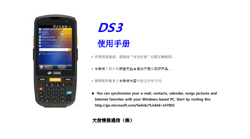
用户指导
种类 A-level (IT device at work) Type registration 用户指导 设备被注册,适合在工作场所使用的电磁波,若错误采购,请直接联系供应商。 此无线设备可能会导致传播的干扰,如此它不能北用于求生服务
※ 在使用前,请仔细阅读警告和注意事项
Contents
• 确保电池正负极不接触任何导电材料(如项链或硬币) Cautions in relation with batteries 另外,确保电池不被损坏牙齿或指甲。影响可能会导致电池爆炸。 . • 使用专用电池,并不比任何其他目的操作本产品提供的电池。 Batteries may explode when damaged, impacted, heated, • flooded or taken apart with a gimlet. Make sure to keep (the batteries out of reach of children 使用非正品电池可能会减少产品的使用寿命,或引起爆炸。 在这种情况下,不允许提供保修服务 ) or pets. • 充电时必须使用,本产品附带的适配器或座充 Do not use the Product in the area with the. risk of explosion. • 使用非证明充电器可能会减少电池寿命或引起爆炸(在这种情况下,不允许提供保修服) • If the Product is wet, do not put it in a device that may heat the terminal (heater, microwave oven, etc.). 关于紫光扫描头注意事项 Heating batteries may cause an explosion, deformation or fault. (Water or any other liquid will change the color of the label inside the terminal. In this case, no warranty service will be provided.) Safety Guideline • Do not use the Product on an airplane or in a hospital. • Do not operate the Product or search a phone number while driving a car. If it is unavoidable, please use a hands-free kit or stop the car. 请勿闪在人和动物的眼睛 • Batteries may become deformed and get in trouble if they are left in a hot and sealed place such as on a dashboard of a car under 这可能会导致视网膜的损害和弱视 the direct sun light.
深圳市发展计划局关于发布《深圳市产业导向目录(2003-2004年)》的通知
深圳市发展计划局关于发布《深圳市产业导向目录(2003-2004年)》的通知文章属性•【制定机关】深圳市发展计划局•【公布日期】2003.06.02•【字号】深计[2003]475号•【施行日期】2003.06.02•【效力等级】地方规范性文件•【时效性】失效•【主题分类】发展规划正文深圳市发展计划局关于发布《深圳市产业导向目录(2003—2004年)》的通知(2003年6月2日深计[2003]475号)为贯彻落实市委三届六次全会和市“十五”计划纲要提出的经济结构战略性调整的目标和任务,积极引导投资方向,优化资源配置,大力培育和发展高新技术产业、先进制造业和现代服务业,促进三次产业协调发展,根据国家产业政策和我国加入WTO的有关承诺,结合市政府及有关部门制定的相关政策和行业组织的指导意见,在多方征求意见的基础上,我局对《深圳市2002年产业导向目录》进行了修订,编制形成《深圳市产业导向目录(2003—2004年)》,现予发布,请遵照执行。
深圳市产业导向目录(2003—2004年)一、凡属鼓励发展的产业和项目,政府有关管理部门应当积极引导企业、金融部门和社会资金增加投资,加快发展,并根据国家、省、市的有关政策和法律法规,给予相应的扶持和服务。
二、凡属限制发展的产业和项目,原则上不准新建项目,不准简单扩大生产能力;情况特殊的,须经市、区政府行业主管部门审核并按规定程序审批。
列入限制发展的产业和项目,宜加快技术改造步伐,积极推进产业、产品结构调整,提高适应能力和竞争能力。
三、除本目录列明的禁止发展的产业和项目外,凡属国家、省、市的有关政策、法律法规明令禁止的,均属禁止发展的产业和项目之列。
对禁止发展的产业和项目,各级计划部门不得立项,各银行、金融机构应停止或限制提供贷款,经贸、建设、工商、国土、环保、消防、海关等部门不得办理新建、扩建有关手续。
有关政策、法律法规明令一定期限内淘汰、关闭、停产的禁止发展产业和项目,政府主管部门应依法检查、督促其按相应规定执行。
PDA配置

数据采集模块(16 模拟+ 16 数字通道) 1kHz并行模数转换模块16A + 16D 通道; 便携式技术参数:- 生产厂家: 德国iba股份有限公司- 坚固的金属19" 1HE便携外壳- 电源为110V..250 AC; 112W- 16模拟和16数字输入- 最快采样速率1ms, 可对所有通道同时采样- 模拟输入: +/- 10V 数字电隔离1.5kV(通道/通道/接地)- 模数转换精度:14 Bits- 数字量输入: < 8V = 逻辑0; 8V-60V = 逻辑1- 电势隔离1.5kV (通道/通道/接地)- FO 端子: 光缆传送器连接PDA系统的FOBx/4-PC-board - 支持由RJ45插口到PCMCIA (-F)卡的即时串行数据输出- 新: 本器件可串连使用(每一链路最多接64A+64D通道) - 新: 4倍超倍采样- 含接线端子插座我们建议在Padu和FOB卡之间用跨接光缆连接。
输入端我们建议採用8通道的配套电缆, 每个Padu用4个。
本器件可与FOB 4i/4o PCI,FOB 4iS/4o PCI, FOB-F, FOB i/o PCI, FOB i/oS PCI, PCMCIA 和PCMCIA-F 卡连用。
SM64-IO; SM128V; SM64-SD16笔记本电脑与过程控制的连接笔记本电脑的PCMCIA插卡(64 模拟+64 数字信号)技术参数:- 生产厂家: 德国iba股份有限公司- 可连接一个Padu16 或Padu32 或Padu8 及其SM64;- 每一列可有8-64个模拟通道(整数或浮点数)- 每一列可有8-64个数字通道- 2 / 3.3 Mbps 速率串行通信用于双端口存储器过程映像传送所有通道可在1毫秒内同步传送- PCMCIA 类型II- 长达7米的RJ11电缆- 支持FO-A 光纤接口请考虑选用PDA Lite(产品代号:5.101)软件包与本接口卡配套过程数据采集及记录系统基本包含一个客户端和一个服务端过程数据采集及记录系统。
PDA介绍

3 2
parallel polarization
1 -3 -2 -1 1 2 3 4
1st order refraction reflection
5
2nd order refraction
Lorenz-Mie
Slide 20 | Zhang Yao | Jul 2006
轨迹效应
检测器 反射
光束光强 高斯分布
3 2 1 1 -1 -2
reflection 1st order refraction
-3 -2 -1
2
3
4
5
perpendicular polarization
-3
Slide 19 | Zhang Yao | Jul 2006
光的散射模式与强度
推荐后向接收角 主散射模式:二次折射 次散射模式:反射 推荐前向接收角: 主散射模式:一次折射 次散射模式:无
FiberPDA与DualPDA的比较 与 的比较
FiberPDA • 可以降低轨迹效应 - 通过使用不同的Mask DualPDA • 可以降低轨迹效应
• 相对于主流速度方向具有
更灵活的布置方式
• 可以判别非球形粒子
- 可以获得更精确的浓度及 通量信息!
• 可以方便的切换到
FiberPDA模式
• 对操作人员有更高的要求
接收探头位置
Slide 23 | Zhang Yao | Jul 2006
FiberPDA与DualPDA的比较 与 的比较
2D发射探头位置
X
1 diameter
Y
Z
FiberPDA会对非球形粒子进行误判 DualPDA可以拒绝非球形粒子
接收探头位置
第二代USBHOSTAndSalve芯片VNC2简介

第二代USBHOSTAndSalve芯片VNC2简介ISP1301——USB OTG收发器完全兼容通用串行总线规范Rev.2.0和OTG补充规范Rev.1.0a概述ISP1301是通用串行总线USB OTG (On-The-Go)收发器,完全兼容通用串行总线规范Rev.2.0和OTG 补充规范Rev.1.0a。
ISP1301可在全速(12Mbit/s)和低速(1.5Mbit/s)速率下收发串行数据。
ISP1301为手持电子提供理想性能,例如手机、数字相机、数字录像机、个人数字助理(PDA)和数字音频播放器。
它为USB专用集成电路(ASIC)、可编程逻辑器件(PLD)和任何系统芯片集(集成USB 主机或者从机功能,但没有USB物理层)提供USB物理层接口。
芯片特性完全兼容以下规范:通用串行总线规范Rev.2.0USB 2.0 On-The-Go补充规范 Rev.1.0aOn-The-Go收发器规范(CEA-2011)Rev.1.0可以在全速(12Mbit/s)和低速(1.5Mbit/s)速率下收发串行数据为系统ASIC或集成USB OTG双角色的芯片集提供理想的功能支持miniUSB模拟车载接口支持多种串行数据接口协议;透明的通用缓冲模式,允许用户控制数据传输方向支持数据线和Vbus脉冲会话请求包含主机仲裁协议(HNP)命令和状态寄存器支持串行I2C总线接口,支持OTG状态和命令控制电源供电输入范围为2.7V-4.5V集成的电荷泵整流器输出5V,电流大于8mA支持外扩电荷泵为数字控制逻辑提供宽范围接口I/O电压(VCC(I/O) = 1.65V-3.6V)在DP、DM、Vbus和ID线上集成8KV ESD保护工业级温度:-40℃-85℃提供无卤无铅封装应用领域移动电话数字相机个人数字助理(PDA)数字录像机(DVR)远翔 USB OTP单片机 (FM8PU83 FM8PU86)低速/全速兼容 IC,FM8PU83: 18PIN,20PIN, 256 BYTE RAM,2.75K ROM,有EP0和EP1,EP2 三个端点,内部高达24M的自振(节省外部晶振) FM8PU86: 18PIN,20PIN,24PIN,256BYTE RAM ,6K ROM,有EP0,EP1,EP2,EP3,EP4,五个端点,可BULK传送.主要应用于:1:USB小数码相框2: USB和RS232/并口/PS2的转换3: USB 密码锁/小U盘4: USB无线激光鼠标笔发射/接收5: USB 无线鼠标、键盘6: 电脑多媒体软件遥控器/接收器7: USB摇杆/玩具飞机模拟遥控器8: USB SKYPE电话9: USB网络彩灯10: USB按摩器/计步器11:USB网卡/USB声卡/USB喇叭12: 运动器材与电脑通信设备13:U盘,读卡器等数据速度传输要求比较快的产品我司是远翔USB产品线的一级代理商,集销售和开发于一体,我USB部门拥有多位经验丰富的USB硬件开发工程师和电脑端USB驱动,应用程序软件开发工程师.能根据客户不同产品的功能选用性价比最好的IC,并在短周期内完成客户的方案!欢迎大家来电洽谈!****中行科技(深圳)有限公司 USB开发部周经理:136******** 0755-********USB OTG 设备既能做主机,又能做设备。
- 1、下载文档前请自行甄别文档内容的完整性,平台不提供额外的编辑、内容补充、找答案等附加服务。
- 2、"仅部分预览"的文档,不可在线预览部分如存在完整性等问题,可反馈申请退款(可完整预览的文档不适用该条件!)。
- 3、如文档侵犯您的权益,请联系客服反馈,我们会尽快为您处理(人工客服工作时间:9:00-18:30)。
**************************************************************************************************************************************************************** PDA-1300
InGaAs PIN Photodiode Module for CATV Receiver
**************************************************************************************************************************************************************** DESCRIPTION
PDA-1300 InGaAs PIN Photodiode series are high quality analog photodetectors designed for AM CA TV receiver applications. These coaxial modules are optically aligned to optimize performance and balance the parameters of responsivity, distortion and back reflection. PDA-1300 series are suitable in forward and return path applications including AM-VSB CA TV, QAM 64/256, PON, FTTC and FTTH receivers. FEATURES
Electro-Optical
l Low Inter-modulation Distortion
l High Responsivity
l Low Back Reflection
Packaging
l Single mode 900 µm fiber with or without a connector
l Single mode 250 µm fiber with or without a connector
ABSOLUTE MAXIMUM RATINGS
Stress in excess of the absolute maximum rating can cause permanent damage to the device. These are absolute stress rating only. Functional operation of the device is not implied at these or any other conditions in excess of these given in the operational sections of the datasheet. Exposure to absolute ratings for extended periods can adversely affect device reliability.
Parameter Symbol Min Max Unit
Forward Current 10 mA
Reverse Current 10 mA
Reverse V oltage 25 V
Power Dissipation P DISS100 mW
Soldering Temperature T solder260/10 o C/sec
Operating Temperature Range T op-40 85 o C
Storage Temperature Range T stg-40 85 o C
CHARACTERISTICS
ELECTRICAL AND OPTICAL CHARACTERISTICS (T C = 25ºC, V R = 12V)
Symbol Parameter Test Conditions Min. Typ. Max. Unit
λ= 1300nm 0.8
A/W
R Responsivity
λ= 1550nm 0.85
Note (1*) -70 dBc
IM2 2nd Order Intermodulation
Modulation
BR Back Reflection λ= 1300 nm, 1550 nm -40 dB
I dark Dark Current V R=5V 1 nA
C Capacitance f=1MHz, Case Ground, V R=5V0.6 0.8 pF
BW Bandwidth 3 dB down, R L=50Ω 2.0 GHz Fiber Length 1.0 1.5 m
1*. IM2 measured at V R=12V, λ=1550nm, P avg=0dBm, MI=0.7, R LOAD=50, f1 = 244 MHz, f2=250MHz
**************************************************************************************************************************************************************** PRECAUTIONS for USE
ESD protection is imperative. Use of grounding straps, anti-static mats, and other ESD protective equipment is recommended when handling or testing an InGaAs PIN or any other junction photodiodes.
Fiber pigtails should be handled with less than 10N pull and with a bending radius greater than 30 mm. MECHANICAL DIMENSION (mm) and PIN ASSIGNMENT
Note: 1.Specifications subject to change without notice.
2. Other PIN assignment is available upon request.
ORDER INFORMATION
Part No.: P D A − 1 3 0 □□。