BZXF85C6V2中文资料
FPGA可编程逻辑器件芯片XCKU085-2FLVA1517E中文规格书
Board InstallationIntroductionThis appendix provides the information required to install, program, debug, and deploy a Xilinx® accelerator board to execute applications created with the SDx® environment. The SDx environment executes in hardware using one of the FPGA boards listed in the application.Installing a BoardThe KCU1500 card is a high-performance reconfigurable computing card for data center applications and includes these features:•XCKU1500-2FLVB2104E FPGA •Four 4GB DDR4 banks (16GB total)The following sections describe how to install a board.Step 1: Set Up the Card and Computer1.Make sure the host computer is completely turned off.2.Install the FPGA board in an open PCIe® slot on the host computer.3.Turn on the host computer.Note:Follow the host computer manufacturer recommendations to ensure proper mountingand adequate cooling.找FPGA 和CPLD 可编程逻辑器件,上赛灵思半导体(深圳)有限公司Step 2: Prepare Board Installation FilesThe SDx environment provides the xbinst utility, which generates firmware and driver files for the target board plugged into the deployment computer.1.Run the following commands to prepare files for the target board installation.See the SDx Command and Utility Reference Guide (UG1279) [Ref6] for more details on the xbinst utility. Depending on the target location, some commands must be run with root or sudo privilege. Otherwise, access permissions must be changed to enable read access for all users on that system.e the following commands to create the deployment area inside/opt/dsa/:$ mkdir /opt/dsa$ mkdir /opt/dsa/xilinx_vcu1525_dynamic_5_1$ cd /opt/dsa/xilinx_vcu1525_dynamic_5_1Note:To install and deploy the KCU1500 files, use xilinx_kcu1500_dynamic_5_0 in step 2 and 3.3.Execute xbinst to install the files needed for the deployment machine. Output similarto the following is displayed:$ xbinst --platform xilinx_vcu1525_dynamic_5_1 -d .****** xbinst v2018.2 (64-bit)**** SW Build 2254440 on Sun Jun 10 18:05:35 MDT 2018** Copyright 1986-2018 Xilinx, Inc. All Rights Reserved.Attempting to get a license: ap_openclFeature available: ap_openclINFO: [XBINST 60-895] Target platform:/opt/Xilinx/SDx/2018.2/platforms/xilinx_vcu1525_dynamic_5_1/xilinx_vcu1525_dynamic_ 5_1.xpfmINFO: [XBINST 60-267] Packaging for PCIe...INFO: [XBINST 60-1032] Extracting DSA to./.Xil/xbinst-1273/xilinx_vcu1525_dynamic_5_1INFO: Adding section [FIRMWARE (3)] using: 'mgmt' (23192 Bytes)INFO: Adding section [SCHED_FIRMWARE (5)] using: 'sched' (9748 Bytes)Successfully completed 'xclbincat'INFO: [XBINST 60-268] Packaging for PLETEINFO: [XBINST 60-667] xbinst has successfully created a board installation directory at /opt/dsa/xilinx_vcu1525_dynamic_5_1.The files are installed in this location:/opt/dsa/xilinx_vcu1525_dynamic_5_1/xbinst:Make a note of the deployment location area because it is required at a later stage.This section refers to this location as the <xbinst-area> or as the deploymentdirectory.4.Install the drivers as described in Step 3: Install Board Drivers.Capabilities: <access denied>Kernel driver in use: xoclKernel modules: xocl03:00.1 Serial controller: Xilinx Corporation Device 6a8f (prog-if 01 [16450]) Subsystem: Xilinx Corporation Device 4351Control: I/O+ Mem+ BusMaster- SpecCycle- MemWINV- VGASnoop- ParErr- Stepping- SERR- FastB2B- DisINTx-Status: Cap+ 66MHz- UDF- FastB2B- ParErr- DEVSEL=fast >TAbort- <TAbort- <MAbort- >SERR- <PERR- INTx-Region 0: Memory at f4000000 (32-bit, non-prefetchable) [size=32M]Region 2: Memory at f8020000 (32-bit, non-prefetchable) [size=128K]Region 4: Memory at f8000000 (32-bit, non-prefetchable) [size=128K]Capabilities: <access denied>Kernel driver in use: xclmgmtKernel modules: xclmgmt。
汉钟压缩机参数表 (2)
LB系列产品为汉钟精机近年来整合低温市场应用经验以及客户需求,精心研发的低温专用螺杆式制冷压缩机。
该系列产品以性能优异,结构简单,使用便捷为设计出发点,特别符合中低温领域市场的应用需求,广泛适用于农业,渔业,肉类,食品业,制程冷却,船舶制冷.冷冻干燥…等多个行业!设计特点1.吸气控制阀设计配合吸气控制阀上的旁通电磁阀逻辑设置,既可在压缩机开机时降低启动电流,又能在压缩机停机时截断高低压反串气流,有效减少压缩机转子的反转时间。
2.无容调机构固定vi设计,与传统螺杆式压缩机相比,避免容调机构繁琐控制,配合吸气控制阀的使用,同样可以实现低负载启动的目的。
3.电机独立冷却设计保证电机在理想温度下运行,有效延长电机使用寿命。
不再因需冷却电机而增加吸气制冷剂的有害过热,冷却电机后的制冷剂进入压缩室进行补气,不会因冷却电机而造成冷量损失,实现更高的能效比,低温工况应用尤为明显。
4.电机冷却膨胀阀自主研发的电机冷却用膨胀阀,具有特殊设计的内部限流孔,保证电机腔内压力,防止气流反窜。
膨胀阀感温包固定在机壳内插孔使得电机温度控制更加精确。
5.可单机系统,可多机并联运用1.单机系统自带油分,并联系统可自由搭配冷量,适用于各种应用领域,可选择不同排气出口方向。
2.接线部分远离吸气口,避免影响电气绝缘。
3.与传统低温螺杆压缩机相比,电气部分减少了结霜现象提高了安全性。
6.高效多段式油分超低压降,专利设计,分段式高效油分设计保证了压缩机运行时的最低抛油率。
LB低温型压缩机机型压缩机电机油充注量油加热器强度试验质量排气量50Hzm3/h转速50Hzr/min润滑方式类别启动方式电压(V)50Hz绝缘等级保护L W bar KgLB-100/ LB-100-P 1062950 压差式供油3相2极鼠笼式感应电动机部分绕阻启动380 F级PTC+PT1004.530035248/233LB-140/ LB-140-P 139 7 290/275LB-180/ LB-180-P 179 7.5 310/295LB-200/ LB-200-P 198 10 440/420LB-230/ LB-230-P 224 10 460/440LB-250/ LB-250-P 257 10.5 464/446LB-280/ LB-280-P 275 11 474/454 LB-360-P 366 - - 370LB-410-P 416 - - 416 注:上表中所有的额定功率不等于压缩机的最大功率;请根据Hanbell选机程序确认压缩机在各种工况下的额定电流、最大持续运行电流值来选择接触器,电源线以及熔断保护元件。
BZX84C16LT1G中文资料
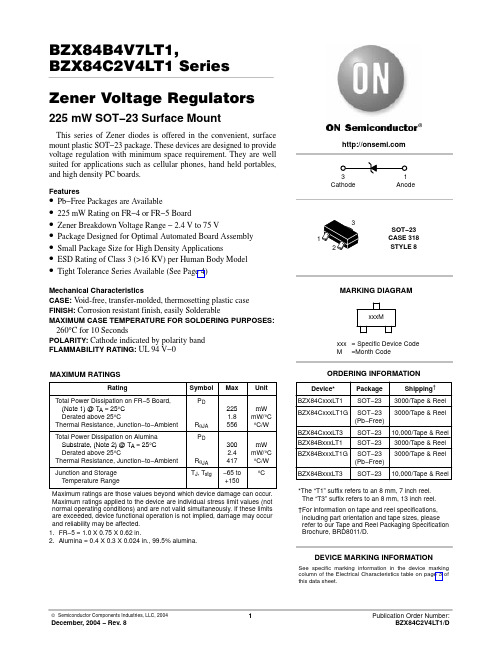
BZX84B4V7LT1,BZX84C2V4LT1 Series Zener Voltage Regulators225 mW SOT−23 Surface MountThis series of Zener diodes is offered in the convenient, surface mount plastic SOT−23 package. These devices are designed to provide voltage regulation with minimum space requirement. They are well suited for applications such as cellular phones, hand held portables,and high density PC boards.Features•Pb−Free Packages are Available•225 mW Rating on FR−4 or FR−5 Board•Zener Breakdown V oltage Range − 2.4 V to 75 V•Package Designed for Optimal Automated Board Assembly •Small Package Size for High Density Applications•ESD Rating of Class 3 (>16 KV) per Human Body Model •Tight Tolerance Series Available (See Page 4)Mechanical CharacteristicsCASE: V oid-free, transfer-molded, thermosetting plastic case FINISH: Corrosion resistant finish, easily SolderableMAXIMUM CASE TEMPERATURE FOR SOLDERING PURPOSES:260°C for 10 SecondsPOLARITY: Cathode indicated by polarity band FLAMMABILITY RATING: UL 94 V−0MAXIMUM RATINGSMaximum ratings are those values beyond which device damage can occur.Maximum ratings applied to the device are individual stress limit values (not normal operating conditions) and are not valid simultaneously. If these limits are exceeded, device functional operation is not implied, damage may occur and reliability may be affected.1.FR−5 = 1.0 X 0.75 X 0.62 in.2.Alumina = 0.4 X 0.3 X 0.024 in., 99.5% alumina.See specific marking information in the device marking column of the Electrical Characteristics table on page 3 of this data sheet.DEVICE MARKING INFORMATION(Pinout: 1-Anode, 2-No Connection, 3-Cathode)(T A = 25°Cunless otherwise noted, V F = 0.95 V Max. @ I F = 10 mA)ELECTRICAL CHARACTERISTICS − BZX84CxxxLT1 SERIES (STANDARD TOLERANCE) (Pinout: 1-Anode, 2-No Connection, 3-Cathode)(T A = 25°C unless otherwise noted, V F = 0.90 V Max. @ I F = 10 mA) (Devices listed in bold, italic are ON Semiconductor Preferred devices.)Z*The “G” suffix indicates Pb−Free package available.ELECTRICAL CHARACTERISTICS − BZX84BxxxL (Tight Tolerance Series)(Pinout: 1-Anode, 2-No Connection, 3-Cathode)(T A = 25°C unless otherwise noted, V F = 0.90 V Max. @ I F = 10 mA)Z*The “G” suffix indicates Pb−Free package available.V Z , T E M P E R A T U R E C O E F F I C I E N T (m V /C )°θV Z , NOMINAL ZENER VOLTAGE (V)− 3− 2012345678Figure 1. Temperature Coefficients (Temperature Range −55°C to +150°C)V Z , T E M P E R A T U R E C O E F F I C I E N T (m V /C )°θ100101V Z , NOMINAL ZENER VOLTAGE (V)Figure 2. Temperature Coefficients (Temperature Range −55°C to +150°C)V Z , NOMINAL ZENER VOLTAGEFigure 3. Effect of Zener Voltage onZener ImpedanceZ Z T , D Y N A M I C I M P E D A N C E ()Ω1000100101V F , FORWARD VOLTAGE (V)Figure 4. Typical Forward VoltageI F , F O R W A R D C U R R E N T (m A )1000100101C , C A P A C I T A N C E (p F )V Z , NOMINAL ZENER VOLTAGE (V)Figure 5. Typical Capacitance 1000100101V Z , ZENER VOLTAGE (V)1001010.10.01I Z , Z E N ER C U R R E N T (m A )V Z , ZENER VOLTAGE (V)1001010.10.01I R , L E A K A G E C U R R E N T (A )µV Z , NOMINAL ZENER VOLTAGE (V)Figure 6. Typical Leakage Current10001001010.10.010.0010.00010.00001I Z , Z E N E R C U R R E N T (m A )Figure 7. Zener Voltage versus Zener Current(V Z Up to 12 V)Figure 8. Zener Voltage versus Zener Current(12 V to 91 V)PACKAGE DIMENSIONSSOT−23TO−236AB CASE 318−09ISSUE AK*For additional information on our Pb−Free strategy and solderingdetails, please download the ON Semiconductor Soldering and Mounting Techniques Reference Manual, SOLDERRM/D.SOLDERING FOOTPRINT*ǒmm inchesǓSCALE 10:1ON Semiconductor and are registered trademarks of Semiconductor Components Industries, LLC (SCILLC). SCILLC reserves the right to make changes without further notice to any products herein. SCILLC makes no warranty, representation or guarantee regarding the suitability of its products for any particular purpose, nor does SCILLC assume any liability arising out of the application or use of any product or circuit, and specifically disclaims any and all liability, including without limitation special, consequential or incidental damages.“Typical” parameters which may be provided in SCILLC data sheets and/or specifications can and do vary in different applications and actual performance may vary over time. All operating parameters, including “Typicals” must be validated for each customer application by customer’s technical experts. SCILLC does not convey any license under its patent rights nor the rights of others. SCILLC products are not designed, intended, or authorized for use as components in systems intended for surgical implant into the body, or other applications intended to support or sustain life, or for any other application in which the failure of the SCILLC product could create a situation where personal injury or death may occur. Should Buyer purchase or use SCILLC products for any such unintended or unauthorized application, Buyer shall indemnify and hold SCILLC and its officers, employees, subsidiaries, affiliates, and distributors harmless against all claims, costs, damages, and expenses, and reasonable attorney fees arising out of, directly or indirectly, any claim of personal injury or death associated with such unintended or unauthorized use, even if such claim alleges that SCILLC was negligent regarding the design or manufacture of the part. SCILLC is an Equal Opportunity/Affirmative Action Employer. This literature is subject to all applicable copyright laws and is not for resale in any manner.PUBLICATION ORDERING INFORMATION。
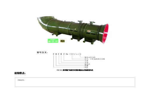
FBCDZ风机参数
YBF132M-4
5.5
7.5
432-228
468-252
170-1440
180-1540
600
660
FBCDZ №9/2×11
FBCDZ №9/2×15
YBF160M-4
YBF160L-4
11
15
900-500
1000-560
270-1800
300-1960
1000
1100
FBCDZ №10/2×18.5
11000
FBCDZ №19/2×75
YBF315M-8
75
4200-2700
190-2000
13600
FBCDZ №20/2×90
YBF315L1-8
90
4900-3100
210-2200
15000
FBCDZ №21/2×110
YBF315L2-8
110
5700-3650
230-2460
16000
№15
5600
640
1900
1125
8300
№16
6000
680
2020
1200
8820
№17
6300
720
2140
1275
9340
№18
6500
760
2260
1350
9860
№19
7000
800
2400
1425
10380
№20
7600
840
2600
1500
10900
№21
8000
880
2700
BZT52C15V中文资料
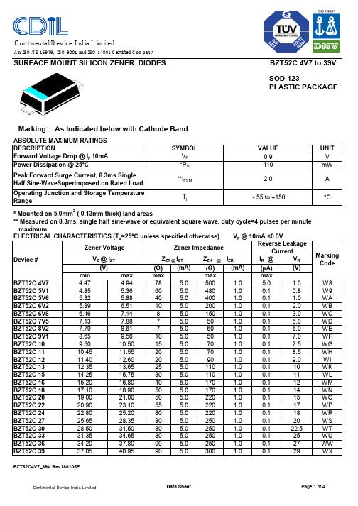
SURFACE MOUNT SILICON ZENER DIODES SOD-123PLASTIC PACKAGEMarking:As Indicated below with Cathode BandABSOLUTE MAXIMUM RATINGS DESCRIPTIONForward Voltage Drop @ I F 10mA * Mounted on 5.0mm 2( 0.13mm thick) land areas** Measured on 8.3ms, single half sine-wave or equivalent square wave, duty cycle=4 pulses per minute maximumELECTRICAL CHARACTERISTICS (T a =25°C unless specified otherwise) V F @ 10mA <0.9VIR @V R (Ω)(mA)(Ω)(mA)(µA)(V)max max max max 4.9478 5.0500 1.0 5.0 1.05.3660 5.0480 1.00.10.85.8840 5.0400 1.00.1 1.06.5110 5.0200 1.00.1 2.07.148 5.0150 1.00.1 3.07.887 5.050 1.00.1 5.08.617 5.050 1.00.1 6.09.5610 5.050 1.00.17.010.5015 5.070 1.00.17.511.5520 5.070 1.00.18.512.6020 5.090 1.00.19.013.6525 5.0110 1.00.11015.7530 5.0110 1.00.11116.8040 5.0170 1.00.11218.9050 5.0170 1.00.11421.0050 5.0220 1.00.11523.1055 5.0220 1.00.11725.2080 5.0220 1.00.11828.3580 5.0250 1.00.12031.5080 5.0250 1.00.122.534.6580 5.0250 1.00.12537.8090 5.0250 1.00.12740.9590 5.0300 1.00.129BZT52C4V7_39V Rev180105EUNIT VALUE 0.9410V WH Operating Junction and Storage Temperature Range- 55 to +150WF WG Z ZK @ I ZK W8V Z @ I ZT MarkingCode4.47 Zener VoltageW9WA WB WC WD WE (V) Z ZT @ I ZT minSYMBOLV F *P D **I FSM Power Dissipation @ 25ºCPeak Forward Surge Current, 8.3ms Single Half Sine-WaveSuperimposed on Rated Load T jA Zener Impedance Reverse LeakageCurrentmW °C2.0BZT52C 4V7BZT52C 5V1BZT52C 5V6Device #BZT52C 6V2BZT52C 6V8BZT52C 7V5BZT52C 8V2BZT52C 9V1BZT52C 10BZT52C 11BZT52C 12BZT52C 13BZT52C 15BZT52C 16BZT52C 18BZT52C 20BZT52C 22BZT52C 24BZT52C 27BZT52C 30BZT52C 33BZT52C 36BZT52C 39 4.855.325.896.467.137.798.659.5010.4511.4012.3514.2515.2017.1019.0020.9034.2037.05WO WP WR 22.8025.6528.5031.35WI WK WL WM WX BZT52C 4V7 to 39V WS WT WU WW WN Continental Device India LimitedAn ISO/TS 16949, ISO 9001 and ISO 14001 Certified CompanyBZT52C4V7_39V Rev180105EComponent Disposal Instructions1. CDIL Semiconductor Devices are RoHS compliant, customers are requested to pleasedispose as per prevailing Environmental Legislation of their Country.2. In Europe, please dispose as per EU Directive 2002/96/EC on Waste Electrical andElectronic Equipment (WEEE).BZT52C4V7_39V Rev180105ECustomer NotesSOD-123PLASTIC PACKAGEBZT52C4V7_39V Rev180105E DisclaimerBZT52C 4V7 to 39VThe product information and the selection guides facilitate selection of the CDIL's Semiconductor Device(s)best suited for application in your product(s)as per your requirement.It is recommended that you completely review our Data Sheet(s)so as to confirm that the Device(s)meet functionality parameters for your application.The information furnished in the Data Sheet and on the CDIL Web Site/CD are believed to be accurate and reliable.CDIL however,does not assume responsibility for inaccuracies or incomplete information.Furthermore,CDIL does not assume liability whatsoever,arising out of the application or use of any CDIL product;neither does it convey any license under its patent rights nor rights of others.These products are not designed for use in life saving/support appliances or systems.CDIL customers selling these products(either as individual Semiconductor Devices or incorporated in their end products),in any life saving/support appliances or systems or applications do so at their own risk and CDIL will not be responsible for any damages resulting from such sale(s).CDIL strives for continuous improvement and reserves the right to change the specifications of its products without prior notice.CDIL is a registered Trademark ofContinental Device India LimitedC-120 Naraina Industrial Area, New Delhi 110 028, India.Telephone + 91-11-2579 6150, 4141 1112 Fax + 91-11-2579 5290, 4141 1119email@ 。
nt855-c280技术参数
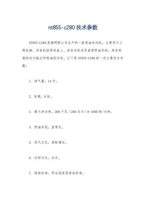
nt855-c280技术参数
NT855-C280是康明斯公司生产的一款柴油发动机,主要用于工程机械、发电机组等设备上。
该发动机采用直喷燃油系统,具有较高的动力输出和燃油经济性。
以下是NT855-C280的一些主要技术参数:
1. 排气量,14升。
2. 缸数,6缸。
3. 最大净功率,209千瓦(280马力)@ 1800转/分钟。
4. 燃油系统,直喷式。
5. 进气方式,涡轮增压。
6. 冷却方式,水冷。
7. 排放标准,符合国家Ⅱ排放标准。
8. 机油容量,38升。
9. 整机重量,约1800千克。
NT855-C280发动机具有结构简单、可靠耐用、维护方便等特点,被广泛应用于各类工程机械和发电机组中,为用户提供稳定的动力
支持。
同时,它也符合国家的排放标准,具有较好的环保性能。
希
望以上信息能够满足你的需求,如果还有其他问题,欢迎继续提问。
聚宝奥峰牌农用车主要技术参数表公告…
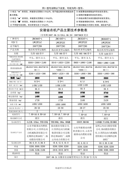
GB18322-2002,GB19756-2005(Ⅰ)
GB18322-2002,GB19756-2005(Ⅰ)
GB18322-2002,GB19756-2005(Ⅰ)
货箱内部尺寸
(长×宽×高)(mm)
3200×1820×390
3690×1820×450
3800×1900×390
3800×1900×390
2280,2385*1520*320
★轴距(mm)
2560
2560
前悬/★后悬(mm)
760/1200
BZX84C3V6V资料
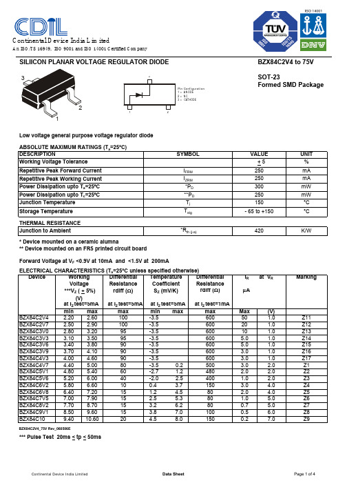
SILIICON PLANAR VOLTAGE REGULATOR DIODEBZX84C2V4 to 75V SOT-23Formed SMD PackageLow voltage general purpose voltage regulator diode ABSOLUTE MAXIMUM RATINGS (T a =25°C)UNIT %Repetitive Peak Forward Current mA Repetitive Peak Working Current mA mW mW °C °CTHERMAL RESISTANCE K/W* Device mounted on a ceramic alumna** Device mounted on an FR5 printed circuit boardELECTRICAL CHARACTERISTICS (T a =25°C unless specified otherwise) Device Temperature DifferentialI R at V RMarkingCoefficient ResistanceS Z (mV/K)rdiff (Ω)µAat I Z test=5mA at I Z test=1mAmin max min max max Max (V)BZX84C2V4 2.20 2.60 -3.560050 1.0Z11BZX84C2V72.50 2.90 -3.560020 1.0Z12BZX84C3V0 2.80 3.20 -3.560010 1.0Z13BZX84C3V3 3.10 3.50 -3.5600 5.0 1.0Z14BZX84C3V6 3.40 3.80 -3.5600 5.0 1.0Z15BZX84C3V9 3.70 4.10-3.56003.0 1.0Z16BZX84C4V34.00 4.60 -3.5600 3.0 1.0Z17BZX84C4V7 4.40 5.00 -3.5 0.2500 3.0 2.0Z1BZX84C5V1 4.80 5.40 -2.7 1.2480 2.0 2.0Z2BZX84C5V6 5.20 6.00 -2.0 2.5400 1.0 2.0Z3BZX84C6V2 5.80 6.60 0.4 3.7150 3.0 4.0Z4BZX84C6V8 6.407.20 1.2 4.580 2.0 4.0Z5BZX84C7V57.007.90 2.5 5.380 1.0 5.0Z6BZX84C8V27.708.70 3.2 6.2800.7 5.0Z7BZX84C9V18.509.60 3.8 7.01000.5 6.0Z8BZX84C109.4010.604.5 8.01500.27.0Z9BZX84C2V4_75V Rev_060506E*** Pulse Test 20ms < tp < 50ms1515152060401015909090801001009595 + 5VALUE max I ZRM Storage Temperature T stg Junction to Ambient*R th (j-a)DESCRIPTIONI FRM Working Voltage Tolerance Power Dissipation upto T a =25ºC SYMBOL *P D ***V Z ( + 5%)(V)at I Z test=5mA Resistance rdiff (Ω)at I Z test=5mA250420300- 65 to +150250Forward Voltage at V F <0.9V at 10mA and <1.5V at 200mAVoltage 150250Differential Working Power Dissipation upto T c =25ºC **P D Junction Temperature T j Pin Configuration1 = A N ODE2 = N C3 =CATHODE12Continental Device India LimitedAn ISO/TS 16949, ISO 9001 and ISO 14001 Certified CompanySILIICON PLANAR VOLTAGE REGULATOR DIODEBZX84C2V4 to 75V SOT-23Formed SMD PackageELECTRICAL CHARACTERISTICS (T a =25°C unless specified otherwise) Device Temperature DifferentialI R at V RMarkingCoefficientResistanceS Z (mV/K)rdiff (Ω)µAat I Z test=5mAat I Z test=1mA min max min max max Max (V)BZX84C1110.4011.60 5.4 9.01500.18Y1BZX84C1211.4012.70 6.0 101500.18Y2BZX84C1312.4014.10 7.0 111700.18Y3BZX84C1513.8015.60 9.2 132000.0510.5Y4BZX84C1615.3017.10 10.4 142000.0511.2Y5BZX84C1816.8019.10 12.4 162250.0512.6Y6BZX84C2018.8021.20 14.4 182250.0514.0Y7BZX84C2220.8023.30 16.4 202500.0515.4Y8BZX84C2422.8025.60 18.4 222500.0516.8Y9at I Z Test=2mA at I Z Test=0.5mABZX84C2725.1028.90 21.4 25.33000.0518.9Y10BZX84C3028.0032.00 24.4 29.43000.0521.0Y11BZX84C3331.0035.00 27.4 33.43250.0523.1Y12BZX84C3634.0038.00 30.4 37.43500.0525.2Y13BZX84C3937.0041.00 33.4 41.23500.0527.3Y14BZX84C4340.0046.00 37.6 46.63750.0530.1Y15BZX84C4744.0050.00 42.0 51.83750.0532.9Y16BZX84C5148.0054.00 46.6 57.24000.0535.7Y17BZX84C5652.0060.00 52.2 63.84250.0539.2Y18BZX84C6258.0066.00 58.8 71.64500.0543.4Y19BZX84C6864.0072.00 65.6 79.84750.0547.6Y20BZX84C7570.0079.0073.4 88.65000.0552.5Y21BZX84C2V4_75V Rev_060506E*** Pulse Test 20ms < tp < 50ms2002152402551301501701808080908025303070at I Z test=5mA at I Z test=5mA max at I Z test=2mAat I Z Test=2mA4045555520Resistance ***V Z ( + 5%)rdiff (Ω)(V)Forward Voltage at V F <0.9V at 10mA and <1.5V at 200mAWorking Differential Voltage Pin Configuration1 = A N ODE2 = N C3 =CATHODE12BZX84C2V4 to 75V SOT-23Formed SMD PackageSOT-23 Package Reel InformationReel specification for W" Packing (13" reel)BZX84C2V4_75V Rev_060506ESOT-23 Formed SMD PackageTape Specification for SOT-23 Surface Mount DeviceS O T -23 T &R3K /reel 10K /reel136 g m /3K p c s 415 g m /10K p c s3" x 7.5" x 7.5"9" x 9" x 9"13" x 13" x 0.5"12 K 51 K 10 K17" x 15" x 13.5"19" x 19" x 19"17" x 15" x 13.5"192 K 408 K 300 K12 k g s 28 k g s 16 k g sPACKAGEN e t W e i g h t /Q t y DetailsS T A N D A R D PACKI N N E R C A R T O N B O XQ t y O U T E R C A R T O N B O XQ t y G r W t SizeSizePacking Detail±0.0114.47.9 – 10.9T R A I L E RF I X I N GT A P EL E A D E R9.2±0.5MAXNOTES:No. of Devices8mm Tape Size of Reel 330 mm (13")10,000 Pcs 8mm Tape Size of Reel 180 mm (7")3,000 Pcs1.The bandolier of 330 mm reel contains at least 10,000 devices.2.The bandolier of 180 mm reel contains at least 3,000 devices.3.No more than 0.5% missing devices / reel. 50 empty compartments for 330 mm reel.15 empty compartments for 180 mm reel.4.Three consecutive empty places might be found provided this gap is followed by 6 consecutive devices.5.The carrier tape (leader) starts with at least 75 empty positions (equivalent to 330 mm).In order to fix the carrier tape a self adhesive tape of 20 to 50 mm is applied. At the end of the bandolier at least 40 empty positions (equivalent to 160 mm) are there.3.15Customer Notes BZX84C2V4 to 75VSOT-23Formed SMD Package1. CDIL Semiconductor Devices are RoHS compliant, customers are requested to pleasedispose as per prevailing Environmental Legislation of their Country.2. In Europe, please dispose as per EU Directive 2002/96/EC on Waste Electrical andElectronic Equipment (WEEE).BZX84C2V4_75V Rev_060506E DisclaimerThe product information and the selection guides facilitate selection of the CDIL's Semiconductor Device(s)best suited for application in your product(s)as per your requirement.It is recommended that you completely review our Data Sheet(s)so as to confirm that the Device(s)meet functionality parameters for your application.The information furnished in the Data Sheet and on the CDIL Web Site/CD are believed to be accurate and reliable.CDIL however,does not assume responsibility for inaccuracies or incomplete information.Furthermore,CDIL does not assume liability whatsoever,arising out of the application or use of any CDIL product;neither does it convey any license under its patent rights nor rights of others. These products are not designed for use in life saving/support appliances or systems.CDIL customers selling these products(either as individual Semiconductor Devices or incorporated in their end products),in any life saving/support appliances or systems or applications do so at their own risk and CDIL will not be responsible for any damages resulting from such sale(s).CDIL strives for continuous improvement and reserves the right to change the specifications of its products without prior notice.CDIL is a registered Trademark ofContinental Device India LimitedC-120 Naraina Industrial Area, New Delhi 110 028, India.Telephone + 91-11-2579 6150, 4141 1112 Fax + 91-11-2579 5290, 4141 1119email@ 。
XGC85履带起重机技术规格书
XGC85履带起重机亮点介绍●安全可靠的控制系统工作和安装两种操作模式方便可靠;紧急电气控制系统、安全及监控装置齐全。
高集成度的液压主阀,简化液压管路,使得故障点大大减少,选配的旁路过滤系统,有效防止液压油乳化,延长系统元器件寿命。
●卓越的操作性能创新性采用微控调节技术,大大提高整车动作的平稳性与精确度。
●强大的起重能力主臂最大起重能力85t/4m,副臂最大起重能力12t/14m。
最长主臂58m,固定副臂最长组合49m+19m。
●丰富的作业工况组合及工况轻松切换(选配功能)主臂工况、带臂端单滑轮及其吊钩的主臂工况、带固定副臂及其吊钩的主臂工况、固定副臂工况、带主臂吊钩的固定副臂工况、带主臂吊钩的臂端单滑轮工况,作业工况组合丰富且主副钩工况能实现一键轻松切换,满足各种吊装需求。
●高效的作业效率丰富的组合动作和理想的单绳速度,作业轻松高效。
●便捷的拆装维护功能配备人字架自扳起功能,无需辅助车辆,轻松实现人字架自扳起;臂架销轴双尖头及二重倒角技术,实现臂架拆装快捷高效;分段组合装配式机棚设计,维护空间大,日常保养更方便。
●灵活的配置组合发动机、泵、阀、机构、马达、回转支承等关键零部件均有国产和进口两种配置,主起升还有快放型配置,各配置之间可实现快速互换,另有主臂走台板、防雷击保护装置、电子水平仪、行走反向等多种功能可供用户选购,可满足不同用户群体需求。
●模块化的部件设计百吨级以下XGC系列产品的固定副臂、臂端单滑轮、平衡重、吊钩能实现通用,可大大减少用户购买XGC系列产品的成本。
优化的运输设计采用结构优化,在85吨级车上实现主机(含底节臂)一体运输,实现全配只需两辆车运输,节约拆装运输成本。
XGC85履带起重机技术规格履带起重机型号:XGC85最大额定起重量:85t/4.0m最大额定起重力矩:341t.m主臂工况最长组合:58 m主臂臂端单滑轮工况最长组合:主臂58m+臂端单滑轮1.1 m固定副臂工况最长组合:主臂49 m +固定副臂19 m单件最大运输重量: 41.2t单件最大运输宽度: 3.3m单件最大运输高度: 3.4m一、产品的部件和系统描述一)上车部分1、臂架组合方式XGC85履带起重机的臂架为高强无缝钢管作为弦管和腹管,辅以高强钢板分段焊接成中间等截面,两端变截面的四弦管空间桁架结构。
BZX84C18-V中文资料

Document Number Small Signal Zener DiodesFeatures•These diodes are also available in other case styles and other configurationsincluding: the SOD-123 case with type designation BZT52 series, the dual zenerdiode common anode configuration in the SOT-23case with type designation AZ23 series and the dual zener diode common cathode configuration in the SOT-23 case with type designation DZ23series.•The Zener voltages are graded according to the international E 24 standard. Standard Zener volt-age tolerance is ± 5 %. Replace "C" with "B" for ± 2 % tolerance.•Silicon Planar Power Zener Diodes •Lead (Pb)-free component•Component in accordance to RoHS 2002/95/EC and WEEE 2002/96/ECWeight: approx. 8.8 mgPackaging Codes/Options:GS18 / 10 k per 13" reel (8 mm tape), 10 k/box GS08 / 3 k per 7" reel (8 mm tape), 15 k/boxAbsolute Maximum RatingsT amb = 25°C, unless otherwise specified1) Device on fiberglass substrate, see layout.Thermal CharacteristicsT amb = 25°C, unless otherwise specified1)Device on fiberglass substrate, see layout.ParameterT est condition Symbol Value Unit Power dissipationP tot300 1)mWParameterTest condition Symbol Value Unit Thermal resistance junction to ambient air R thJA 420 1)°C/W Junction temperature T j 150°C Storage temperature rangeT S- 65 to + 150°CElectrical CharacteristicsPartnumber MarkingCodeZenerVoltageRangeDynamic Resistance T estCurrentTemp.Coefficientof ZenerVoltageTestCurrentReverse LeakageCurrentV Z @ I ZT1r zj @ I ZT1r zj @ I ZT2I ZT1αVZ @ I ZT1I ZT2I R@ V R VΩmA10-4/°C mAµA Vmin max min maxBZX84C2V4-V Z11 2.2 2.670 (≤100)2755-9.0-4.01501 BZX84C2V7-V Z12 2.5 2.975 (≤100)300 (≤600)5-9.0-4.01201 BZX84C3V0-V Z13 2.8 3.280 (≤95)325 (≤600)5-9.0-3.01101 BZX84C3V3-V Z14 3.1 3.585 (≤95)350 (≤600)5-8.0-3.0151 BZX84C3V6-V Z15 3.4 3.885 (≤90)375 (≤600)5-8.0-3.0151 BZX84C3V9-V Z16 3.7 4.185 (≤90)400 (≤600)5-7.0-3.0131 BZX84C4V3-V Z174 4.680 (≤90)410 (≤600)5-6.0-1.0131 BZX84C4V7-V Z1 4.4550 (≤80)425 (≤500)5-5.0+2.0132 BZX84C5V1-V Z2 4.8 5.440 (≤60)400 (≤480)5-3.0+4.0122 BZX84C5V6-V Z3 5.2615 (≤40)80 (≤400)5-2.0+6.0112 BZX84C6V2-V Z4 5.8 6.6 6.0 (≤10)40 (≤150)5-1.0+7.0134 BZX84C6V8-V Z5 6.47.2 6.0 (≤15)30 (≤80)5+2.0+7.0124 BZX84C7V5-V Z677.9 6.0 (≤15)30 (≤80)5+3.0+7.0115 BZX84C8V2-V Z77.78.7 6.0 (≤15)40 (≤80)5+4.0+7.010.75 BZX84C9V1-V Z88.59.6 6.0 (≤15)40 (≤100)5+5.0+8.010.56 BZX84C10-V Z99.410.68.0 (≤20)50 (≤150)5+5.0+8.010.27 BZX84C11-V Y110.411.610 (≤20)50 (≤150)5+5.0+9.010.18 BZX84C12-V Y211.412.710 (≤25)50 (≤150)5+6.0+9.010.18 BZX84C13-V Y312.414.110 (≤30)50 (≤170)5+7.0+9.010.18 BZX84C15-V Y413.815.610 (≤30)50 (≤200)5+7.0+9.010.050.7 V Znom.BZX84C16-V Y515.317.110 (≤40)50 (≤200)5+8.0+9.510.050.7 V Znom.BZX84C18-V Y616.819.110 (≤45)50 (≤225)5+8.0+9.510.050.7 V Znom.BZX84C20-V Y718.821.215 (≤55)60 (≤225)5+8.0+1010.050.7 V Znom.BZX84C22-V Y820.823.320 (≤55)60 (≤250)5+8.0+1010.050.7 V Znom.BZX84C24-V Y922.825.625 (≤70)60 (≤250)5+8.0+1010.050.7 V Znom.BZX84C27-V Y1025.128.925 (≤80)65 (≤300)2+8.0+100.50.050.7 V Znom.BZX84C30-V Y11283230 (≤80)70 (≤300)2+8.0+100.50.050.7 V Znom.BZX84C33-V Y12313535 (≤80)75 (≤325)2+8.0+100.50.050.7 V Znom.BZX84C36-V Y13343835 (≤90)80 (≤350)2+8.0+100.50.050.7 V Znom.BZX84C39-V Y14374140 (≤130)80 (≤350)2+10+120.50.050.7 V Znom.BZX84C43-V Y15404645 (≤150)85 (≤375)2+10+120.50.050.7 V Znom.BZX84C47-V Y16445050 (≤170)85 (≤375)2+10+120.50.050.7 V Znom.BZX84C51-V Y17485460 (≤180)85 (≤400)2+10+120.50.050.7 V Znom.BZX84C56-V Y18526070 (≤200)100 (≤425)2+9.0+110.50.050.7 V Znom.BZX84C62-V Y19586680 (≤215)100 (≤450)2+9.0+120.50.050.7 V Znom.BZX84C68-V Y20647290 (≤240)150 (≤475)2+10+120.50.050.7 V Znom.BZX84C75-V Y21707995 (≤255)170 (≤500)2+10+120.50.050.7 V Znom. Document Number 85763Document Number Electrical CharacteristicsPartnumberMarking CodeZener Voltage Range Dynamic ResistanceTest CurrentT emp. Coefficient of Zener Voltage T est CurrentReverse LeakageCurrentV Z @ I ZT1r zj @ I ZT1r zj @ I ZT2I ZT1αVZ @ I ZT1I ZT2I R @ V R V ΩmA10-4/°C mAµAVminmax min max BZX84B2V4-V Z50 2.35 2.4570 (≤100)2755-9-41501BZX84B2V7-V Z51 2.65 2.7575 (≤100)300 (≤600)5-9-41201BZX84B3V0-V Z52 2.94 3.0680 (≤95)325 (≤600)5-9-31101BZX84B3V3-V Z53 3.23 3.3785 (≤95)350 (≤600)5-8-3151BZX84B3V6-V Z54 3.53 3.6785 (≤90)375 (≤600)5-8-3151BZX84B3V9-V Z55 3.82 3.9885 (≤90)400 (≤600)5-7-3131BZX84B4V3-V Z56 4.21 4.3980 (≤90)410 (≤600)5-6-1131BZX84B4V7-V Z57 4.61 4.7950 (≤80)425 (≤500)5-52132BZX84B5V1-V Z585 5.240 (≤60)400 (≤480)5-34122BZX84B5V6-V Z59 5.49 5.7115 (≤40)80 (≤400)5-26112BZX84B6V2-V Z60 6.08 6.32 6.0 (≤10)40 (≤150)5-17134BZX84B6V8-V Z61 6.66 6.94 6.0 (≤15)30 (≤80)527124BZX84B7V5-V Z627.357.65 6.0 (≤15)30 (≤80)537115BZX84B8V2-V Z638.048.36 6.0 (≤15)40 (≤80)54710.75BZX84B9V1-V Z648.929.28 6.0 (≤15)40 (≤100)55810.56BZX84B10-V Z659.810.28.0 (≤20)50 (≤150)55810.27BZX84B11-V Z6610.811.210 (≤20)50 (≤150)55910.18BZX84B12-V Z6711.812.210 (≤25)50 (≤150)56910.18BZX84B13-V Z6812.713.310 (≤30)50 (≤170)57910.18BZX84B15-V Z6914.715.310 (≤30)50 (≤200)57910.050.7 V Znom.BZX84B16-V Z7015.716.310 (≤40)50 (≤200)589.510.050.7 V Znom.BZX84B18-V Z7117.618.410 (≤45)50 (≤225)589.510.050.7 V Znom.BZX84B20-V Z7219.620.415 (≤55)60 (≤225)581010.050.7 V Znom.BZX84B22-V Z7321.622.420 (≤55)60 (≤250)581010.050.7 V Znom.BZX84B24-V Z7423.524.525 (≤70)60 (≤250)581010.050.7 V Znom.BZX84B27-V Z7526.527.525 (≤80)65 (≤300)28100.50.050.7 V Znom.BZX84B30-V Z7629.430.630 (≤80)70 (≤300)28100.50.050.7 V Znom.BZX84B33-V Z7732.333.735 (≤80)75 (≤325)28100.50.050.7 V Znom.BZX84B36-V Z7835.336.735 (≤90)80 (≤350)28100.50.050.7 V Znom.BZX84B39-V Z7938.239.840 (≤130)80 (≤350)210120.50.050.7 V Znom.BZX84B43-V Z8042.143.945 (≤150)85 (≤375)210120.50.050.7 V Znom.BZX84B47-V Z8146.147.950 (≤170)85 (≤375)210120.50.050.7 V Znom.BZX84B51-V Z82505260 (≤180)85 (≤400)210120.50.050.7 V Znom.BZX84B56-V Z8354.957.170 (≤200)100 (≤425)29110.50.050.7 V Znom.BZX84B62-V Z8460.863.280 (≤215)100 (≤450)29120.50.050.7 V Znom.BZX84B68-V Z8566.669.490 (≤240)150 (≤475)210120.50.050.7 V Znom.BZX84B75-VZ8673.576.595 (≤255)170 (≤500)210120.50.050.7 V Znom. Document Number 85763Typical Characteristics (Tamb = 25 °C unless otherwise specified)Figure 1. Forward characteristics Figure 2. Admissible Power Dissipation vs. Ambient Temperature Figure3. Pulse Thermal Resistance vs. Pulse Duration1811418115Figure 4. Dynamic Resistance vs. Zener CurrentFigure 5. Capacitance vs. Zener VoltageFigure6. Dynamic Resistance vs. Zener Current1811718118Document Number Figure 7. Dynamic Resistance vs. Zener CurrentFigure 8. Thermal Differential Resistance vs. Zener Voltage Figure9. Dynamic Resistance vs. Zener Voltage18120Figure 10. Temperature Dependence of Zener Voltage vs. ZenerVoltageFigure 11. Change of Zener Voltage vs. Junction TemperatureFigure 12. Temperature Dependence of Zener Voltage vs. ZenerVoltage18124°C18136 Document Number 85763Figure 13. Change of Zener Voltage vs. Junction TemperatureFigure 14. Change of Zener voltage from turn-on up to the point ofthermal equilibrium vs. Zener voltageFigure 15. Change of Zener voltage from turn-on up to the point ofthermal equilibrium vs. Zener voltage181261813718138Document Number Figure 16. Breakdown CharacteristicsFigure17. Breakdown Characteristics1811118112 Document Number 85763Layout for R Theta;JA testThickness: Fiberglass 0.059 in. (1.5 mm)Copper leads 0.012 in. (0.3 mm)Figure18. Breakdown Characteristics18113Package Dimensions in mm (Inches)Document Number Ozone Depleting Substances Policy StatementIt is the policy of Vishay Semiconductor GmbH to1.Meet all present and future national and international statutory requirements.2.Regularly and continuously improve the performance of our products, processes, distribution and operatingsystems with respect to their impact on the health and safety of our employees and the public, as well as their impact on the environment.It is particular concern to control or eliminate releases of those substances into the atmosphere which are known as ozone depleting substances (ODSs).The Montreal Protocol (1987) and its London Amendments (1990) intend to severely restrict the use of ODSs and forbid their use within the next ten years. Various national and international initiatives are pressing for an earlier ban on these substances.Vishay Semiconductor GmbH has been able to use its policy of continuous improvements to eliminate the use of ODSs listed in the following documents.1.Annex A, B and list of transitional substances of the Montreal Protocol and the London Amendmentsrespectively2.Class I and II ozone depleting substances in the Clean Air Act Amendments of 1990 by the EnvironmentalProtection Agency (EPA) in the USA3.Council Decision 88/540/EEC and 91/690/EEC Annex A, B and C (transitional substances) respectively. Vishay Semiconductor GmbH can certify that our semiconductors are not manufactured with ozone depleting substances and do not contain such substances.We reserve the right to make changes to improve technical designand may do so without further notice.Parameters can vary in different applications. All operating parameters must be validated for each customer application by the customer. Should the buyer use Vishay Semiconductors products for any unintended or unauthorized application, the buyer shall indemnify Vishay Semiconductors against all claims, costs, damages, and expenses, arising out of, directly or indirectly, any claim of personal damage, injury or death associated with such unintended or unauthorized use.Vishay Semiconductor GmbH, P.O.B. 3535, D-74025 Heilbronn, Germany Document Number 85763。
BAT54C中文资料_数据手册_参数
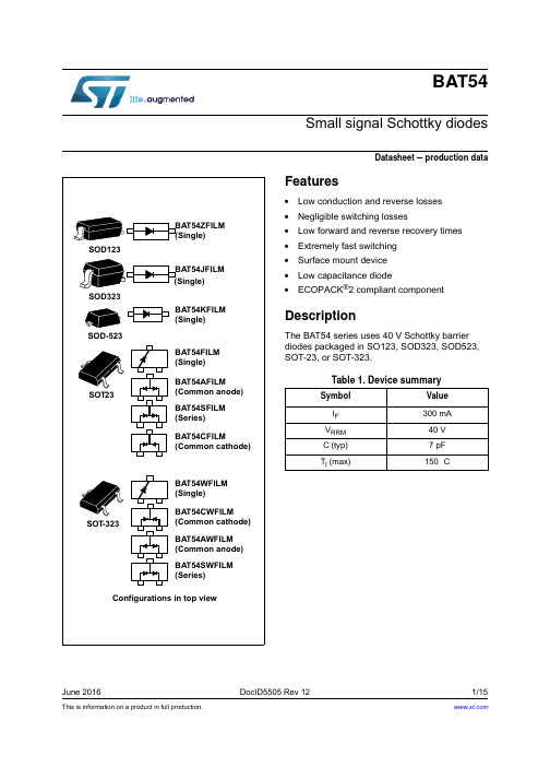
Typ.
Max. Unit
1 µA
100
240
320
400 mV
500
900
Symbol
Table 5. Dynamic characteristics
Parameter
Test conditions
C Diode capacitance
current (typical values)
C(pF) 10
F=1MHz
VOSC=30mVRMS Tj=25°C
1.E+00 IFM(A) 1.E-01
Tj=100°C
1.E-02 1.E-03
Tj=50°C Tj=25°C Tj=-40 °C
VR(V) 1
1.E-04
VFM(V)
1
10
100
0.0 0.1 0.2 0.3 0.4 0.5 0.6 0.7 0.8 0.9 1.0 1.1 1.2 1.3
1
Characteristics
BAT54
Table 2. Absolute ratings (limiting values at Tj = 25 °C, unless otherwise specified)
Symbol
Parameter
Value
Unit
VRRM IF
IFSM Tstg Tj TL
0.148
Figure 12. SOD123 footprint dimensions in mm (inches)
6/15
防爆空调技术规格书.doc
壁挂式空调(防爆)技术规格书一、总则本技术规格书规定了吐哈油田分公司三塘湖采油厂购置空调在设计、制造、配套、验收、现场服务等方面的最低要求。
出卖人应根据要求的技术参数,按照相应的标准规范进行设计、制造、配套、和验收,并提供良好的售后服务。
本项目不限制品牌型号,可选择国内知名品牌,所选型号功能参数不能低于本技术规格书的要求。
二、环境条件壁挂式空调(防爆)在鄯善卸油台值班室使用,值班室为彩钢板野营房,在油气区内。
鄯善所处地区属温带大陆性干旱气候,干旱少雨,冬季严寒,夏季酷热,四季多风,降雨极稀,蒸发量大,热量丰沛,日照时间长,冬季昼夜温差悬殊。
主要如下:3.1年平均气温 8-10℃3.2最高气温 42℃(曾出现过48℃高温)3.3最低气温 -30.9℃3.4年平均风速 4-6 m/s3.5瞬时最大风速 40 m/s3.6年平均降水量 33.90mm3.7最大冻土深度 150cm3.8最大积雪深度 5cm3.9年沙尘暴日数 20天3.10使用地点: 鄯善卸油台值班室三、物资需求计划表3.1、空调必须提供如下附件:3.1.1配备空调连接安装附件(必须提供足够长度的室内机和室外机连接管路,防爆插头、插座等)3.1.2提供空调一个遥控操作面板。
3.1.3提供空调:使用说明书:一份;产品合格证:一份;出厂检验报告:一份;保修单:一份;装箱单:一份。
四、技术要求及参数4.1型号:BKFR-35(1.5P)4.2制冷量:3500W;4.3能效等级:不低于2级;4.4电源:220V,50Hz;4.5符合《中国石油天然气股份有限公司吐哈油田分公司新增设备能效限额管理规定》中空调器能效限额要求。
4.6防爆空调等级为ExdibmbIICT4Gb.4.7设计制造执行标准:4.7.1 GB3836.1-2010<爆炸性环境第1部分:设备通用要求>4.7.2 GB3836.2-2010<爆炸性环境第2部分:由隔爆外壳d保护的设备>4.7.3 GB3836.3-2010<爆炸性环境第3部分:由增安型e保护的设备>4.7.4 GB3836.4-2010<爆炸性环境第4部分:由本质安全型i保护的设备>4.8.5 GB3836.9-2014<爆炸性环境第9部分:由浇封型m保护的设备>4.8.6 GB12476.1-2013<可燃性粉尘环境用电气设备第1部分:通用要求>4.9 出卖人负责空调的安装调试五、质量保证5.1. 出卖人应提供空调完好工作的质保期,质保期为正常运行后一年。
CLG856高配置装载机维修资料(电器系统)概要
目录重要安全信息第一部分 --------------------------------------------------------------------------------------------------------------维修注意事项第二部分 --------------------------------------------------------------------------------------------------------------------电源系统第三部分 --------------------------------------------------------------------------------------------------------------------仪表系统第四部分 --------------------------------------------------------------------------------------------------------------自动复位系统第五部分 -----------------------------------------------------------------------------------------------------------------------灯组件第六部分 -----------------------------------------------------------------------------------------------停车制动与动力切断线路第七部分 --------------------------------------------------------------------------------------------------------------倒车警报系统第八部分 -----------------------------------------------------------------------------------------------------刮水器与清洗器系统第九部分 -----------------------------------------------------------------------------------------------------------------电喇叭线路第十部分-----------------------------------------------------------------------------------------------------------------点烟器线路第十一部分 ----------------------------------------------------------------------------------------------ZF 半自动变速操纵系统第十二部分 -----------------------------------------------------------------------------------------------------------------空调电路重要安全信息很多操作、维护、维修等方面的意外事故是由于没有遵守基本的安全规则及安全防范措施引起的。
