UL1310 讲义
UL1310测试项目资料
项目测试项目标准条款标准要求测试方法
不能把故障测试后的设备立刻从插座上取下,还要能承受前
面说述的拉力,压力测试,插脚在产品内部的连接部位不能
出现高阻状态。
(可通过测量循环测试前后插脚之间出的温度
和插脚连接处的温度来判断连接部位是否处于高阻状态)
19 Abuse tests滥用测
试Clause46 设备的外壳应承受Clause 46.2 – Clause
46.5要求的机械破坏测试,测试后满足如
下要求:
-用Figure 16.2的测试指不能碰到危
险带电部件
-不能出现其他有触电危险的状态
如果是系列申请,机械测试选产品重量最
重的型号进行测试。
1. Impact on direct plug-in units直插式设备冲击测试
(Clause 46.2):
-三个样品分别以不同的面从914mm的高度跌落至一硬
木表面(跌落测试不直接施加于插脚),每个样品跌落3
次。
测试后样品需进行耐压测试;
-如果客人选择用多个样品进行测试,则测试按下图进行。
2. Impact on cord connected units软线连接设备冲击测试。
UL1310 讲义
功率和电流
Not inherently limited 在任何负载下不超过
此类电源具有可以自动切断输出电路的措施。 动作的时间也有要求,除非使用的是经认证符合动作时间要求的且额定 值不大于上表的保险丝。
功率和电流
Not inherently limited 动作时间
ห้องสมุดไป่ตู้
距离
•不同极性带电体间 •带电和不带电金属件间 •带电体和金属外壳间 应满足表24.1和24.2的距离要求 表24.1 – 外壳有开孔 表24.2 – 外壳无开孔
户外产品的额外测试
Rain Test 1小时后, 进行耐压和绝缘电阻测试. Rainproof: 允许进水, 但能高过带电体, 且带电体上不能有水附着. Raintight: 不允许进水.
紫外线测试 & 材料浸水测试 (UL746C) 非金属外壳材料
垫圈材料测试 对用于防水的垫圈材料的弹性和韧性的要求
39.8.3/39.8.4(backfeed)的测试。
非正常测试
Backfeed Protection相关测试 39.8.1/.2: 在充电器输出端接: 1. 指定类型的最大容量和电压的充满的电池,或 2. 空载电压等于充电器额定输出直流源,短路电流不小于200A。 然后在尽可能靠近输出端的地方接能引起最大倒灌电流的阻性负载, 或短路。5秒后读倒灌电流值,不应超过8A。
0.56Nm not for traveler •W 794g •测量时, 输出线不计入其中.
直插式产品
•插头位置 A 5.1mm A 7.9mm (for toy) 直插式产品插入复式插座中的一个时, 不应影响插头完全插 入旁边的其它插座, 除非根本插不进去.
电源线
可接受的电源线
UL1310培训讲义
Class 2 Power Units-UL 1310 (5th Edition)(Dated May 3, 2005, Last Revise Date Jan. 31, 2006)-CAN/CSA-C22.2 No. 223-M91 (2nd Edition)(Dated June 1991)Agenda(大綱)➢Scope (范围)➢Class 2 Definition (Class 2定义)➢Key Construction Requirements (结构要求重点)•Enclosure/Protective Devices/Coil Insulation/Input Connections/Output Connections/Accessibility of Live Parts/Separation of Circuits/Grounding/Spacing(外壳/保护装置/变压器绝缘/输入连结/输出连结/带电体可接触性/线路隔离/间距) ➢Key Performance Requirements (测试要求重点)•Electrical Tests (电气测试)•Mechanical Tests (机构测试)➢Caution Marking & Instruction (警告标示及使用说明)➢Relative SPS Standard Instruction (相关标准简介)Scope (範圍)Indoor and outdoor use Class 2 power supplies and battery chargers for use on alternating current branch circuits with a maximum potential of 150 V to ground.连接于对地最大电压150 V的交流电源上之室内及户外用Class 2电源适配器及充电器➢Portable direct plug-in units provided with 15 A blade configurations for use on nominal 120 or 240 V branch circuits➢Cord- and plug-connected units provided with a 15 A or 20 A attachment plug configuration(构造) ➢Units permanently connected to the input supplyInput power does not exceed 660 W under any possible condition of output loading (最大输入功率不超过660W)Class 2 Definition (Class 2定义)Class 2 Voltage Limitation(Class 2电压限制)Voltage Type Indoor-use units Outdoor-use unitsSinusoidal, ac 30 V, rms 30 V, rms (UL)Non-sinusoidal, ac 42.4 V, peak 42.4V, peak (UL)Pure dc 60 V (UL) 60 V (UL)Non-sinusoidal ac or dc42.4 V (CUL)42.4 V (CUL)Note: For AC Systems - If the product exceeds the 15 V rms and 21.2 V peak; and is not greater 30 V rms and 42.4 V peak;For DC Systems - If the product exceeds the 30 V for continuous dc The product shall be marked as below:US –“Class 2 not wet,” “Class 3 wet”Canada –“Class 2 not wet,” “Class 1 wet”Max. O/P current for inherently limited units (先天限制的)(30.1)The maximum output volt-amperes shall not be more than 100 volt-amperes (最大输出不得超过100V A)Max. O/P current and V A for not inherently limited units (非先天限制的) (Cl30.2)Circuitvoltage (Vmax) a,b ac ordc VoltsMax. nameplate ratings Max. o/p current (I max)c, amperes Max. o/p V A (V A max)d Max.overcurrent protection rating, A V-A Amperes 0 – 20 Over 20 to 30 Over 30 to 60, dc only5.0 X Vmax100 100 5.0100/Vmax 100/Vmax1000/Vmax 1000/Vmax 1000/Vmax250e 250 2505.0100/Vmax 100/Vmaxa V max is the maximum output voltage regardless of load with rated input voltage applied.b Voltage ranges shown are for sinusoidal alternating current and continuous direct current. For nonsinusoidal alternating current, maximum voltage shall be greater than 42.4 volts peak. For direct current interrupted at a rate of 10 – 200 hertz, maximum voltage shall not be greater than 24.8 volts.c I max is maximum ampere output regardless of load after operation as specified in 30.2.1. d V A max is maximum volt-ampere output regardless of load after operation as specified in 30.2.1.e Maximum volt-amperes is 350 if maximum circuit voltage is 15 or less. Construction (結構)Mechanical Assembly--Direct Plug-In (机构组立-插墙式) (Cl7.11)Mechanical Assembly--Direct Plug-In (机构组立-插墙式)(7.16)Determination of perimeter of units with rounded edgesA = 5.1 mm for UL (Marking for Mounting(固定件)Tab)A = 8.0 mm for CUL (No Mounting Tab)If a mounting tab be provided, the following conditions shall be met:a) Use on a or 15-ampere, 125- 250-volt receptacle (NEMA 1-15R or 5-15R or 6-15 R);b) A screw [No. 6 mounting screw (3.5 mm major diameter, 32 threads/inch)] is provided and constructed to secure to a duplex (双方的) receptacle that has a center screw;c) For a unit without a grounding pin, the mounting tab is constructed to be mounted to both grounding and non-grounding receptacles; andd) Marked “CAUTION” and the following or the equival ent:1) “Risk of Electric Shock –Disconnect power to the receptacle before installing or removing the unit. When removing receptacle cover screw, cover may fall across plug pins or receptacle may become displaced;”2) “Use only with duplex receptacle having center screw;” and3) “Secure unit in place by receptacle cover screw”Metal Enclosure (金属外壳)Indoor use:➢ A sheet metal thickness not less than that in Table 8.1. The thickness of sheet metal other than steel or aluminum shall not be less that than in Table 8.1 for uncoated steel (8.4)➢Iron and steel parts shall be protected against corrosion (抗蚀)by galvanizing (镀锌), plating (电镀), enameling (上釉), or other equivalent means if the corrosion (侵蚀)of such unprotected parts results in a risk of fire, electric shock, or injury to persons (9.1)Outdoor use:➢ A type 3R, 3S, or 4X enclosure evaluated with UL 50 (CCN: CYIV or BGUZ), is not required to be subjected to the Rain Test (56.1)➢ A metallic enclosure shall be protected against corrosion(57.5)➢Copper, bronze(青铜), and brass(黄铜) containing no less than 80 percent copper, or stainless steel may be used without additional protection against corrosion (57.6)Enclosure (塑料外壳)Indoor use:➢UL: Flammability (燃烧等级):Min. V-2 (UL 94)CUL: Flammability: Min. V-1 (UL 94)➢Resistance to arcing properties: UL 746C➢Moisture absorptive propertiesOutdoor use:➢ A type 3R, 3S, or 4X enclosure evaluated with UL 50 (CCN: CYIV or BGUZ), is not required to be subjected to the Rain Test➢An enclosure of a unit shall be constructed to reduce the risk of electric shock due to weather exposure and shall prevent live parts, electrical components, or wiring (not identified (鉴别)for use while in contact with water) from becoming wetProtective Devices (保护装置)➢The protective device may be located in either the primary or secondary circuit (可在初级或次级线路) ➢Type of protective device: Thermostat, Thermal Cutoff, Positive Temperature Coeffecient (PTC) Resistor, Negative Temperature Coeffecient (NTC) Resistor, Fuse, Eutectic Material (双合金材料) ➢An protective device shall not open when delivering its rated output (正常额定输出时, 保护装置不可做动) ➢ A protective device for a not inherently limiting Class 2 power unit shall not be of the automatic reclosing type(自动恢复式) and shall be rated with Table 30.2 and provided in secondary circuitCoil Insulation (变压器线圈绝缘)➢Any type or thickness of insulation may be used if the coil withstands the induced potential test (13.2.8.b)➢Tape used as insulation in lieu of (代替)spacing shall provide a continuous 1/32 inch (0.8 mm) minimum wide bent up edge against the bobbin flanges (使用胶带当绝缘以抵押间距要求则须提供至少0.8 mm宽的反折)(13.2.3)A flanged, bobbin-wound transformer shall be subjected to the output loading test continued for 15 day s if the transformer has:➢The primary winding wound over the secondary winding or the secondary winding wound over the primary winding; and➢The primary winding insulated from the secondary winding by a layer of insulating material other than coil form/bobbinThe test is not required to be applied for 15 days if the following requirements are met:➢Multiple layered winding wire ◊UL 746A, UL 746B, UL 746C➢Meet spacing requirement ◊ Table 24.1, Table 24.2➢Alternate spacing ◊ UL 840➢Triple insulated wiring ◊ Subject 2353 (OBJT2)Input Connection (输入连结)Multiple Voltage Rated Power Unit (多输入电压电源适配器)Definition (定义):A power unit with a rated voltage range (such as 100 – 240 volts) or more than one discrete voltage rating (such as 120/240 volts)Intended for Use By Travellers (旅行者用电源适配器)Definition (定义): (14.1.4)A multiple voltage rated direct plug-in power unit with a 125 V, 15 A (parallel) input blade configuration, or a multiple voltage rated cord-connected power unit with a non-detachable power supply cord terminating in a 125 V, 15 A (parallel) blade plugRequirements for Intended for Use By Travellers (旅行者用电源适配器的要求): (14.1.4)a) The blade assembly shall be a 125 volt, 15 amp configuration(构造);b) The power unit shall employ a user adjustable (可调整的)voltage selector and comply with Switch Position Test, or be capable of operating at different voltages without user adjustment;c) The input voltage rating shall include nominal 120 volt;d) The power unit shall be marked as specified in 51.8; ande) The power unit shall be provided with instructions as specified in 54.4A multiple voltage rated power unit intended for use by travelers shall be marked as follows with the following or equivalent: (51.8)a) "See instruction manual for use in countries other than the U.S.A." orb) “See instructions for input voltage conversion.” orc) “See instructions if the input plug does not fit the power outlet”Instructions shall include (a) - (c) or the equivalent, as appropriate. The items shall be preceded by "IMPORTANT SAFETY INSTRUCTIONS - SAVE THESE INSTRUCTIONS" and "DANGER - TO REDUCE THE RISK OF FIREOR ELECTRIC SHOCK, CAREFULL Y FOLLOW THESE INSTRUCTIONS" in letters of 1/8 inch (3.18 mm) high or in a readily visible contrasting text (54.4)a) "Be sure voltage selector is in correct voltage position before plugging in." The instructions shall also specify the procedures to follow for changing the voltage selectorb) "For use in the U.S.A., the voltage selector switch must be placed in the 120 volt position. For use in countries other than the U.S.A., the voltage selector may need to be placed in other than the 120 volt position. Confirm the voltage available at each country location before using the product"c) "For connection to a supply not in the U.S.A., use an attachment plug adapter of the proper configuration for the power outlet, if needed." or “If the shape of the plug does not fit the power outlet, use an attachment plug adaptor of the proper configuration for the power outlet"Direct Plug-in Units (插墙式)Indoor use:➢Blade assembly meet UL 1681, UL 1310 par. 7.16 and 7.17➢ A direct plug-in unit employs a manually operated line connected single-pole switch or a fuse with an accessible contact, it shall employ a polarized- or grounding-type blade assembly (如有手动电压选择开关或可接触式保险丝, 则需是极性或有接地的blade) (14.1)➢ A direct plug-in unit employs folding or retractable blades for the input connectors, it shall comply with Direct Plug-in Security of Input Contacts Test (Blade Endurance Test for 6000 cycles) (44.2)Outdoor use:➢Brass containing of blades no less than 80 percent copper (57.6)Cord Connected Units (桌上型)Indoor use:➢Table 14.1 and cord external length shall not be less than 6 feet (1.8 m) and not smaller than No. 18 AWG(14.2.1 & 52.12)DC input units:➢Shall be provided with a vehicle battery adapter in compliance with UL 2089(14.3.1)For UL:A power unit marked adjacent to the appliance coupler to inform the user to see the instruction manual for proper (适当的) selection of the power supply cord and the instructions shall specify selection of a cord complying with the requirements in 14.2.1 is not required to be provided with the detachable power supply cord. (51.7)For CUL: The detachable power supply cord shall not be optional.(分离式电线一定要随货出)Outdoor use:➢Shall be at least as serviceable as junior(低级的) hard service cord type SJW, SJOW, SJTW, SJTOW, SW, SOW, STW, or STOW➢Shall employ a 3-conductor grounding type supply cordException: A power unit that does not have parts required to be grounded is not required to employ a grounding type supply cord➢Shall be a non-detachable power supply cord with an attachment plug➢ A unit shall be provided with an output cord, terminals, insulated leads, or output connectors. A battery charger with backfeed protection shall be provided with an output cord terminating in a connector, or a connector a ttached to or integral (完整的) with the enclosure (15.1.1)(输出线, 端子, 绝缘导线或输出接头皆可当输出连结;充电器的输出线需带有接头或是接头附在外壳上) ➢For CUL, permanently attached cord terminating in a connector shall be providedIndoor use:Output Wiring:➢Shall be stranded conductors(绞线) having insulation not less than 0.013 inch (0.33 mm) thick, and permanently attached to the output circuit. The wiring shall extend at least 6 feet (1.8 m) outside the unit (15.2.1) ➢For a cord-connected unit (桌上型) with a minimum 6 feet (1.8 m) power-supply cord, the output flexible cord (permanently attached to the power unit or provided in the form of a separate cord set) shall be of anydesirable length. The maximum combined length of the input and output cords shall not exceed 20 feet (6.1 m)(15.2.2)Outdoor use:Output Wiring:➢Shall be suitable for outdoor use, “W” rated, and sunlight (UV) resistant (抗紫外线) as applicable to outdoor cords (60.1)➢For CUL, shall be of the type in Table 11 of the Canadian Electrical Code, Part I, and shall at least of the type SPT-2, PXWT or CXWT and suitable for wet locationsOutput Wiring:Strain Relief Bushing (套管)be suitable for outdoor use and sunlight (UV) resistant (抗紫外线)[(QMFZ2) with f2 code or (QMTT2)]Output terminals:A terminal plate shall be not less than 0.030 inch (0.76 mm) thick, and shall provide not less than two full threads in the metal for the binding screw (15.3.1) (安上接线螺丝或螺栓的接线板应由黄铜或其它非铁金属,或镀钢制成,厚度不少于0.030 吋(0.76 毫米),和在金属内应提供不少于两个完全的螺纹给接线螺丝使用。
led 电源 ul标准

led 电源 ul标准LED电源UL标准。
LED(Light Emitting Diode)作为一种高效、节能、环保的照明产品,已经在各个领域得到了广泛的应用。
而LED电源作为LED照明产品中不可或缺的部分,其质量和安全性更是至关重要。
在LED电源的安全标准中,UL标准是其中非常重要的一部分。
UL标准是由美国安全实验室(Underwriters Laboratories)制定的,是全球公认的安全认证标准之一。
在LED电源领域,UL标准主要包括UL8750和UL1310两个部分。
UL8750是专门适用于LED模块和灯具的电源装置的标准,而UL1310则是适用于工业控制设备的标准。
首先,UL标准对LED电源的输入电压范围、输出电流和电压等参数有着严格的要求。
LED电源在设计时必须符合UL标准对于输入和输出电压的要求,以确保LED电源在正常工作时不会对人身和财产造成危害。
此外,UL标准还规定了LED 电源的绝缘等级和绝缘材料的要求,以确保LED电源在使用过程中不会因为绝缘不良而引发安全事故。
其次,UL标准对LED电源的防护措施和安全性能有着详细的规定。
LED电源在设计和生产过程中必须符合UL标准对于过载保护、短路保护、过热保护等方面的要求,以确保LED电源在异常情况下能够及时停止输出电流,避免对灯具和其他设备造成损坏。
此外,LED电源的外壳材料、防护等级和接地方式也都在UL标准中有着具体的规定,以确保LED电源在使用过程中能够有效地防止触电和火灾等安全事故。
最后,UL标准还对LED电源的可靠性和环境适应性做出了要求。
LED电源在设计和生产过程中必须经过严格的可靠性测试,以确保LED电源在长时间工作和恶劣环境下仍然能够保持稳定的性能。
此外,UL标准还要求LED电源在使用过程中要符合环保要求,不得含有对人体和环境有害的物质,以确保LED电源的安全和环保性能。
综上所述,LED电源的UL标准是确保LED照明产品安全和可靠性的重要保障。
电源安规

电源安规1.UL1310,EN60950安规中针对安全距离方面有什么不同?及HI-POT测试方面具体的指标又有什么不同答: UL1310的安全距离不管是基本还是加强绝缘都是要求8mm,EN60950对于安全距离的要求是,基本绝缘时空间距离2mm、沿面距离2.5mm,加强绝缘时空间距离4mm、沿面距离5mm;HI-POT测试具体的指标有什么不同,简单来讲就是测试电压不同。
2.L线与N线之间,初级与次级之间,高压部分与地之间,及高压部分与不带电金属部分之间的距离(空间距离及爬电距离)在美规及欧规中各为多少?答: L-N的空间距离3.2mm、沿面距离6.4mm;高压对地的空间距离3.2mm、沿面距离6.4mm;高压对金属外壳距离6.4mm;一次对二次又分线性的空间距离3.2mm、沿面距离6.4mm,开关式的空间距离6.4mm、沿面距离9.5mm,以上的距离是UL1310里有开孔的电源适配器的一些距离上的要求。
L-N的空间距离1.6、沿面距离6.4mm;高压对地的空间距离1.6mm、沿面距离6.4mm;高压对金属外壳距离6.4mm;一次对二次又分线性的空间距离1.6mm、沿面距离6.4mm,开关式的空间距离4.8mm、沿面距离6.4mm,以上的距离是UL1310里无开孔的电源适配器的一些距离上的要求。
L线到N线如果是保险丝前的话要求距离是2.5mm,保险丝后没有要求。
一次和二次我以前就讲过,高压对地视为基本绝缘,要求距离就是基本绝缘,高压对金属外壳也是视之为基本绝缘。
1.安规中230v和120v电源L---N,L----G,N---G布线最小距离是多少?一次测和二次测的最小距离又是多少?L,N,G两者之间:对于230V,沿面间距2.5mm,空间间距2.0mm对于120V,沿面和空间间距均为1.2mm一次侧和二次测之间:对于230V,沿面间距5.0mm,空间间距4.0mm对于120V,沿面和空间间距均为1.2mm2.保险丝两边对应的PCB也有距离要求吧,请问是多少mm呢?保险丝两脚间CR 2.5MM CL2.0MM有关初次级的间距,应该参照工作电压,再去查找安规相应的对应电压的CR,CL距离欧规(CE)的安全距离是计算出来的,具体如何计算我也不太清楚,但对变压器一般来说是P——S安全距离为5mm,50HZ P——S 3.5KV 1mA 60S生产中卧式:1.两边用5mm档墙,但所需绕线宽度较大.2.交叉绕线,绕初级时次级侧用5mm,初级用3mm;绕次级时初级侧用5mm,次级侧用3mm.但其初次级偶合较差且漏感较大.3.初、次级侧全部用2-3mm档墙,所有引脚加套管.但其生产时效率较慢.3.初级或次级全部加套管,用3mm档墙;另一侧全部用5mm档墙立式:1.底部(PIN端)加5mm档墙,顶部用3mm档墙2.所有引脚加套管,底部用2-3mm档墙,顶部用3mm档墙.一般为安全起见,都不会选择2mm而统一用3mm档樯.德规(VDE)一般安全距离为6mm 50HZ P-S 3.75KV 1mA 60S P,S-C 2.0KC 1mA 60S生产可同上,只不过将5mm改为6mm.且如果用引脚加套管时档墙不可<3mm。
UL1310结构要点

UL 1310 (Class 2電源供應器)結構要點-11. Scope(適用範圍)•插牆式電源供應器,用於15 A,120 Vac或240 Vac的電力系統;或電源線連接式電源供應器,用於15 A或20 A線電壓對地不大於150 V的電力系統;電源供應器搭配絕緣變壓器,以輸出直流或交流,且輸出符合NEC (國家電工法規)規定之Class 2之等級。
•可附有一個DC jack,以供車用電池供電之用。
•不論於何種負載之下,輸入功率不得大於660 W。
•並不適用於祇單純由DC供應之產品,如車用inverter等。
2. Glossary(名詞解釋)•Bonding Conductor —用以連接接地之導體。
•Injury to Persons —電擊以外會實際造成人體損傷,如機械傷害。
•Risk of Electric Shock —超過Vrms, 60 Vdc),或漏電流測試時,超過mA。
5. Mechanical Assembly(機構要求)•Lampholder, Switch或其他類似零件,須有除了表面磨擦力外之防止旋轉的措施,如使用lock washer。
•可更換的燈,須置於二次側線路上,且更換時不須打開外殼。
•~ 重心的量測與要求。
•直插式adaptor使用mounting tab須符合下列條件:1.僅適用於15 A、125 V的插座。
2.雙插孔的插座中間須有螺絲孔,以供固定。
3.無接地Pin的adaptor、mounting tab,須設計為可裝在接地或非接地型插座。
4.依據49、2、4標示。
•直插式外殼之邊緣到插頭片導體之距離至少要mm (CSA要求至少要8 mm),若為玩具使用,至少要為mm。
6. Enclosure(外殼)•外殼上任何開孔均不得於大於(以測試手指或測試pin,不得碰觸危險電壓)。
•金屬外殼的厚度須符合Table ,如鋼板為mm,鍍鋅鋼板為mm,非鐵金屬板為mm。
•塑膠外殼除了本標準所列測試外,亦須符合UL 746C。
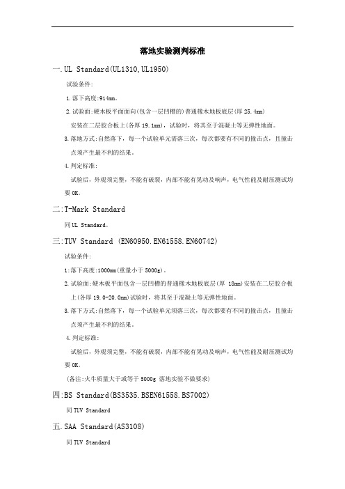
落地实验测判标准
落地实验测判标准
一.UL Standard(UL1310,UL1950)
试验条件:
1.落下高度:914mm。
2.试验面:硬木板平面面向(包含一层凹槽的)普通橡木地板底层(厚25.4mm)
安装在二层胶合板上(各厚19.1mm),试验时,将其至于混凝土等无弹性地面。
3.落地方式:自然落下,每一个试验单元需落三次,每次都要有不同的撞击点,且撞击
点须产生最不利的结果。
4.判定标准:
试验后,外观须完整,不能有破裂,内部不能有晃动及响声,电气性能及耐压测试均要OK。
二:T-Mark Standard
同UL Standard。
三:TUV Standard (EN60950.EN61558.EN60742)
试验条件:
1:落下高度:1000mm(重量小于5000g)。
2.试验面:硬木板平面包含一层凹槽的普通橡木地板底层(厚18mm)安装在二层胶合板
上(各厚19.0-20.0mm)试验时,将其至于混凝土等无弹性地面。
3.落下方式:自然落下,每一个试验单元须落三次,每次都要有不同的撞击点,且撞击
点须产生最不利的结果。
4.判定标准:
试验后,外观须完整,不能有破裂,内部不能有晃动及响声,电气性能及耐压测试均要OK。
(备注:火牛质量大于或等于5000g 落地实验不做要求)
四:BS Standard(BS3535.BSEN61558.BS7002)
同TUV Standard
五.SAA Standard(AS3108)
同TUV Standard。
申请UL1310的注意事项
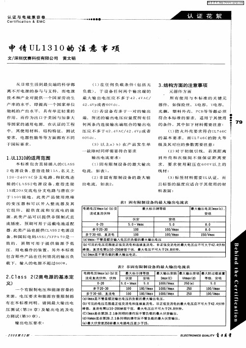
最 大标 示牌 等 级
最 大输 出 电流 I a () m xc . 安 培
安培
50 . 8. 0
多于 2 — 0 03 多于3 - 0 0 6 ,直 流 电
i0 0 10 0
1 0V a 0 /mx 1 0V a 0 /mx
80 . 10 Va 5 /m x
( ) m x 不管 是额 定 输入 电压 的负载 的最 大输 出 电压 aV a :
多于2 — 0 0 3 多于 3 — 0 直流 电 06 ,
1 0V a 1 0/ mx 0 /m x 00 Va 1 0V a 1 0/ mx 0 /m x 00 V a
来 源 。 电压 要 求 和 能 源 容 量 限制 都 有 在 本 标 准 列 明 。 请 阅 最 大 输 出 电 压 测 试 ( 28章 )及 输 出 电 流 及 电 第 力 测 试 ( 30章 )。 第 输 出 电压 要求 :
维普资讯
丛 与 皇 磁 菱 容 量
Cerii t f Cat On & E M C i
申 请 U 31 1 0的 温 L
文 / 圳 优 赛 科技 有 限公 司 黄 文韬 深
从 日常 生 活 到 最 尖 端 的 科 学 都 离 不 开 电 源 的 参 与 与 支持 , 而 电源 负
料表 面 ;
( 1)固 有 限 制 设 备 的 最 大 输 出
电 流 , 如 表 1。 ’
2电 源 设 备 , 指 连 接 15 名 义 上 意 A,
120 40 —2 VAC分 支 电 路 , 软 线 连 和
( )非 固 有 限 制 设 备 的 最 大 输 2 出 电 流 , 如 表 2。
( 3)以 上 a)b)在 产 品 发 生 单
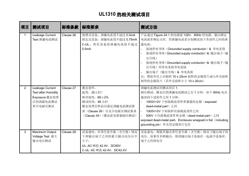
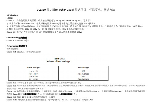
UL1310 测试项目,标准要求,测试方法 第7版(March 9, 2018)
测试,变压器的输出电压基本上是正弦的或连 1)一次电路和可接触的非带电金属部件;以及
续的直流,并且可以改变。施加的耐压将从 0 2)一次电路和二次电路。
开始增加,直到达到规定的测试水平,并在该 --b) 对于 28.3 或 30.2.3 描述的产品,1000Vac+2 倍次级绕为标准中提到打交流电可能会有超额漏电流),把 Y 电
容移除之后再打 AC 电 2V+1000(还是在 Y 的点位两端,只不过 Y 移除
Construction 结构部分 Clause 7- clause 24(略)
Performance 测试部分
测试设定要求:
Clause 25.1 测试电压(由额定电压决定)
Clause 25.2 一个样品也许会做不止一个测试,如果这个样品在之前的测试中没有毁坏的话。 Clause 25.3 对于将装置连接至电源电路的试验,分支电路应通过分支电路保护装置进行保护,该装置的额定值等于该装置可连接的最小额定插座。对于永久连接到输入
voltage 最大输出电压
出端子之间的最大输出电压应不大于:
如果有多路输出,则将输出端子连接在一起或不连接时,端子之间的
UL:AC 峰值 42.4V,DC60V
电压
CUL:AC 峰值 42.4V,DC42.4V
4
Maximum input test 最 Clause 29 设备在任意负载(含任意输出组合在一起的输 对 于 输 出 电 流 已 整 流 的 设 备 , 其 负 载 端 接 一 个 可 调 电 阻 与 一 个
UL1310 第 7 版(March 9, 2018)-测试项目,标准要求,测试方法
Introduction 1 Scope Clause 1.1 产品使用隔离变压器,最大输出不能超过 AC 电 42.4Vpeak, DC 电 60V,适用于: a) 使用在标称 120Vac/240Vac,最大每相电压为 150V 对地的市电上的直插式设备(15A 插脚) b) 使用在标称 120Vac/240Vac,最大每相电压为 150V 对地的市电上的带插头线(电源线)或插脚作为一个附件的设备(附件插脚为 15A 或 20A) c) 使用在标称电压 600V 或 600V 以下的 AC 或 DC 每相电,且设备永久连接到电源 Clause 1.2 其中 a)“直插设备”和 b)“带线/带插设备”输入功率不能超过 660W
UL1310 ISB1-55989-589-6 说明书
CLASS 2 POWER UNITS-UL1310
1
UL1310
ISB1-55989-589-6
CLASS 2 电源设备安全标准 CLASS 2 POWER UNITS
Created by KINGSTREET Page 1 of 1
PDF created with FinePrint pdfFactory trial version
2.14 线性设计设备 UNIT, LINEAR DESIGN 利用分支电流频率变压器设计的设备若操作不是根据电路图。
2.15 可携设备 UNIT, PORTABLE 除了驻立式单位或半常置装配的单位外的其它设备。
2.16 半常置装配设备 UNIT, SEMIPERMANENT MOUNTED 拥有配件钮的直接插入设备.根据本标准的范围,半常置装配的设备需要符合可携设备的规条(除 非有特别列明)
装配 5 机械集成
5.1 设备应组合和集成使它有足够力度及坚固来防止妄用,避免因空间缩少而做成完全或部份设备松
Created by KINGSTREET Page 6 of 6
PDF created with FinePrint pdfFactory trial version
下,例如在不超过特定限制的温度下,和只用于有被认可的限定情况下。
4 总类 4.1 量度单位 4.1.1 若一个单位的数值被加括号在另一个单位数值之后,那第二个数值可能只是约数。第一个数 值是所需的。 4.1.2 除非其它事项指明,电流与电压值都是均方根。 4.2 无日期的关联 4.2.1 任何在本标准的规条内的代码或标准并没有出现日期的关联均会定为最新版本代码或标准。 4.3 术语 4.3.1 “电源设备”一词会被用于在本标准规条内的所有电源,电池充电器和变压器。
UL1310 测试项目解析
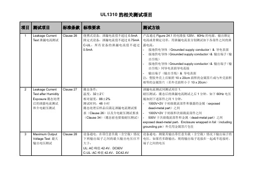
测试项目
标准条款
标准要求
测试方法
1
Leakage Current Test泄漏电流测试
Clause 26
便携式设备:泄漏电流值不超过0.5mA
固定式设备:泄漏电流值不超过0.75mA
C-UL:所有设备的泄漏电流值不超过0.5mA
产品通过Figure 24.1的电路接120V,60Hz的电源,输出额定电流或者额定功率,用泄漏电流表分别测试如下各部件之间的泄露电流:
Clause 31
非固有保护产品所提供的保护装置在通以标准中Table 31.1里规定的测试电流时,应在标准中Table 31.1里规定的时间内开路。上述测试完成后要做耐压测试。
这个测试后,产品须满足如下结果:
-没有火光或熔化的金属从产品里面出来,纱布没有烧焦、着火和起燃。
-产品没有产生开孔,以使电压超过42.4Vpeak的危险带电部件暴露出来
如果有多人输出,应考虑输出之间连接或不连接时的最大输入功率。
5
Output Current and Power Test输出电流和功率测试
Clause 30
在此测试中,器具下垫两层白色薄纸,上面用两层纱布遮住。
最大输出电流和最大输出功率不应超过标准中的值(Table 30.1和Table 30.2)。
如果产品有多路输出,,怎把输出相互连接,重复上述的测试。
C-UL:测试电路须连接一个class A GFCI,输出要接到地(Ground)。
这个测试后,产品须满足如下结果:
-没有火光或熔化的金属从产品里面出来,纱布没有烧焦、着火和起燃。
-产品没有产生开孔,以使电压超过42.4Vpeak的危险带电部件暴露出来
-(C-UL)Class A GFCI没有开路
最新UL1310中文版

CLASS 2 POWER UNITS-UL1310
1
UL1310
ISB1-55989-589-6
CLASS 2 电源设备安全标准 CLASS 2 POWER UNITS
Created by KINGSTREET Page 1 of 1
PDF created with FinePrint pdfFactory trial version
生危险。 5.4 设备应被构造使在使用时不需打开或拿走外壳。 5.5 每个灯座、开关或相似组件应坚固地装置和加强表面与表面的摩擦力以防止它们回旋。例如,使
用螺栓垫圈的方法可以防止该单孔装配装置回旋。
例外一︰不可更换灯泡的灯座( 如由不可移动宝石密封的灯泡内的氖光灯或汽车方向灯) 不需 要防止回旋若旋转不可减低少于最低可接受值的空间,或在带电连接时产生压力。
Created by KINGSTREET Page 2 of 2
PDF created with FinePrint pdfFactory trial version
SEPTEMBER 25,2001
CLASS 2 POWER UNITS-UL1310
3
42.输入接触的直接插入式固定测试 43.输出连接器安全测试 44.滥用测试 45.接合导线测试 制造及产品测试 46.耐压测试 47.接地连续性测试 额定值 48.总类 标记 49.详细资料 规章 50.使用手册 附录一 标准零件
3 组件 3.1 除了在第3.2 条列明外,本标准包含的产品组件应符合组件的要求。本标准包含的常用标准组件, 请参阅附录一。
3.2 一个组件不需符合特别规条若 a) 本标准包含的产品内,组件含不需要使用的特性或特征。 b) 该规条已在本标准被取代。
UL1310Class2电源安全标准
UL1310Class2电源设备平安标准名目简介1.范围本标准适用于室内和室外2型电源设备的电池充电器。
这些设备利用一个隔离变压器及包含的组件提供交流或直流的输出,每个2型电源设备提供的输出符合美国国家电气标准,即ANSI/NFPA70。
当产品为低压电动设备时,其在使用交流电的时候最大输出电压不得超过42.4V,在使用直流电的时候最大输出电压不得超过60V。
以下为注重事项:a)当我们使用额定120或240V的交流电压时,便携式和非永久式的直插式设备接好后,铜足处产生15A电流,电路对地产生最大150V的电势。
b)当我们使用额定120或240V的交流电压时,软线式设备和插头连接处会产生15或20A电流,并对地面产生最大150V的电势。
c〕单位永久连接到使用额定输进电压600V以下交流或直流电路中。
直插式设备和软线式设备装配有一个完整的打火组件,并以适宜的电池配适器与信息技术设备相连接,通过其相应的数据情况调整其直流电的大小。
这些单位利用一个尽缘变压器和许多相关组件来提供交/直流电流输出,每个2型电源产生的输出应与美国国家电气标准相一致,即ANSI/NFPA70。
当产品为低压电动设备时,其在使用交流电的时候最大输出电压不得超过42.4V,在使用直流电的时候最大输出电压不得超过60V。
本标准包含那些产品在任何情况的输出负载下,输进的电源不超过660W。
本标准不包含连接在设备或系统内的电源设备可能所发出的妨碍。
1.4产品的最终用途可能会包括额外的考虑,可能会收到额外的需求,在其中寻到并依据产品适用性来确定最终产品标准,参考51.4中相关联的例子:a)由工具带来的机械风险;b)由无线设备和外部天线连接增强的静电;c)因为医疗设备而出现的震动限制;d)由装饰照明产品带来的消防风险。
本标准不包含用于替在开启引擎时的发动机激活器充电的产品。
此类产品包含于UL1236。
本标准包含2型产品,如本标准所定义,预期用于玩具类。
UL1310安全标准
UL1310安全标准UL 1310总则1 范围1.1 这些要求适应于直接插⼊式变压器,此类变压器单元有15A⼑形闸且⽤在120V或240V标定电压的电路中。
直接插⼊式变压器是⽤次级输出为低压的降压式隔离变压器,和可以含有整流器和其它元件作为交流或直流电源使⽤。
直接插⼊式变压器使⽤CLASS II电路与国家电⽓符号⼀致;电⽓驱动,预置初级供给低压电源。
1.2 这些要求也应⽤于封闭式直接插⼊式变压器,此类变压器可给医疗和⽛医设备、视频、⾳频或⽆线电设备同时使⽤。
2 概要2.1 为了这个标准,给出下述定义:2.2 CLASS II——提供有限电压和容量的电源。
对电压和储能限制的要求如本标准所⽰。
参考26节,次级开路电压;28节,输出电流和功率。
2.3 单元——为直接插⼊式变压器,除⾮另外说明。
2.4 焊接导体——本体⾦属连接到地端的导体2.5 外壳——防⽌接近、内在的电击危险或致⼈伤害的表⾯或环绕结构。
2.6 普通⼯具——钳⼦和⼀字或⼗字头(PHILIPS TYPES)镙丝⼑。
2.7 室内使⽤——在室内或湿⽓不可能接触到的地⽅使⽤。
3 元件3.1 本标准涉及到的产品的元件应满⾜该元件的要求,⽽且按照其认可的额定和其它的⽤途的界限来使⽤。
4 测量单元4.1 如果⼀测量值⽤圆括号括起跟在⼀值后,第⼆个值可能为⼤致值,第⼀个值是要求值。
结构5 总则6.1 变压器应使所有元件可靠地固定。
6.2 变压器在使⽤时其外壳不应被打开或移动6.3 灯头、开关和⼩型元(部)件应固定紧,即使表⾯之间的摩擦也不能转动。
6.4 变压器的次级电路中应⽤线连接可换的灯泡,并且在更换时不必打开外壳,在更换灯泡时初级中带电的部件应不会触及到。
6.5 在⼀单元或控制元件的外表⾯构成⼀单元外壳的⼀部分,这⼀部件应满⾜43点不合理使⽤的要求。
6.6 如果外壳上外在的开关元件或控制性元件;的外表⾯构成⼀单元外壳的⼀部分,这⼀部件应满⾜43点不合理使⽤的要求.6.7 ⼀单元中的重⼒、长度和重量的最在可接受的⼒矩中⼼应满⾜A、B、C和D所有的要求,参看6.11和6.12.A.、WY/Z⽐率不超过1361g;B、WY/S⽐率不超过1361g;C、WX值不超过0.56N.mD、⼀单元的重量不能超过794g6.8 在6.10章节中⽤到的符号定义W为单元的重量Y为如图6.1所⽰的距离Z为如图6.1所⽰的Z1、Z2距离的较⼩者;S为如图6.1所⽰的S1、S2距离中的较⼤者;X为如图6.1的所⽰的X2、X2距离中的较中者6.9 6.10所⽰的要素和重量按如下决定:A、有输出电缆(线)的单元,该电缆(线)在外壳处切掉,或者在拉⼒释放装置处切掉,如果拉⼒释放装置在外壳外⾯。
UL1310(电源设备安全标准)
CLASS 2 电源设备安全标准 CLASS 2 POWER UNITS
Created by KINGSTREET Page 1 of 1
PDF created with FinePrint pdfFactory trial version
SEPTEMBER 25,2001
SEPTEMBER 25,2001
CLASS 2 POWER UNITS-UL1310
1
UL1310
ISB1-55989-589-6
欢迎访问:亚洲电子研发中心
本站常驻二十多位的专业工程师,与大家一起是讨论交流充电器,电池技术 ;EDA,CAD设计;开关电源,磁芯技术;照明,镇流器 ,节能灯 ,LED,LCD;单片机,PLC,DSP,自动控制;无线电技术,天线,卫星接收,遥控,超 声波技术;电视,影碟机,收录机,HI-FI,家用电器技术与维修;电脑技术;通信技术 ;网站建设与源码;ISO,UL,CE,IEC,GS等各种安规认证。 欢迎各位专业人士 和广大电子电脑爱好者加入讨论交流!
2.14 线性设计设备 UNIT, LINEAR DESIGN 利用分支电流频率变压器设计的设备若操作不是根据电路图。
2.15 可携设备 UNIT, PORTABLE 除了驻立式单位或半常置装配的单位外的其它设备。
2.16 半常置装配设备 UNIT, SEMIPERMANENT MOUNTED 拥有配件钮的直接插入设备.根据本标准的范围,半常置装配的设备需要符合可携设备的规条(除 非有特别列明)
1.范围 1.1 本标准包含直接插入的CLASS 2 电源设备,意指连接15A,名义上120-240VAC分支电路,和软线 连接的CLASS2电源设备,意指连接15或20A交流电分支电路与潜在少于150V接地。此类产品使 用绝缘的变压器和可以并入整流器及其它组件,提供直流和交流电的能源.此类产品可以提供非强 制式直流插座,预期可用于运截电池适配器.此类产品也提供CLASS 2 电源设备,和国际电码 ANSI/NFPA 70是一致的,预期可用于提供能源予低压、用电操作的装置。 1.2 本标准包含那些产品在任何情况的输出负载下,输入的电源不超过660W。 1.3 本标准不包含连接在设备或系统内的电源设备可能所发出的影响。 1.4 有特别用途记号的产品(如用于音响、无线电报或影像类的设备﹔医科或牙科的设备﹔或其它工具) 可能会被列入合适的产品标准内的附加要求。 1.5 本标准不包含用于替在开启引擎时的发动机激活器充电的产品。此类产品包含于UL 1236。 1.6 本标准包含CLASS 2 产品,如本标准所定义,预期用于玩具类。此类产品也符合UL 697 的标准。 1.7 本标准不包含不属于CLASS 2 输出的产品,也不包含用于替轮椅或类似的移动性设备充电的电 池充电器。此类产包含于UL1012。 1.8 本标准不包含用于连接能源供应,有CLASS 2 变压器存在的产品。此类产品包含于UL 1585 。 1.8.1 本标准不包含只接受直流电源供电的产品。此类产品包含于UL458。 1.9 在特色、特征、组成物、材料或系统上有别于其它标准,而其中牵涉到火灾、电击或伤人的产品, 需要以适当的附加组成物和试品设备作评定,对此类产品的用户保持应的安全程度,以达到本标 准的原本预期的意图。
UL1310_22 Spacing requirement
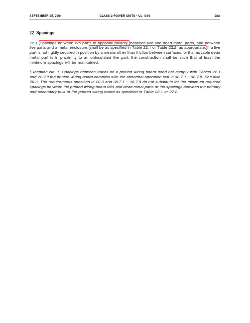
SEPTEMBER25,2001CLASS2POWER UNITS-UL131028A22Spacings22.1Spacings between live parts of opposite polarity,between live and dead metal parts,and between live parts and a metal enclosure,shall be as specified in Table22.1or Table22.2,as appropriate.If a live part is not rigidly secured in position by a means other than friction between surfaces,or if a movable dead metal part is in proximity to an uninsulated live part,the construction shall be such that at least the minimum spacings will be maintained.Exception No.1:Spacings between traces on a printed wiring board need not comply with Tables22.1 and22.2if the printed wiring board complies with the abnormal operation test in38.7.1–38.7.5.See also 20.3.The requirements specified in20.3and38.7.1–38.7.5do not substitute for the minimum required spacings between the printed wiring board foils and dead metal parts or the spacings between the primary and secondary foils of the printed wiring board as specified in Table22.1or22.2.Exception No.2:A unit complying with the requirements in22.4–22.8need not comply with this requirement.22.1.1For the purpose of determining working voltage in units employing nonlinear circuitry:a)when the dc value is used,the peak value of any superimposed ripple shall be included;b)non-repetitive transients(due,for example,to atmospheric disturbances)shall be disregarded;c)the voltage of a Class2circuit is regarded as zero for determination of through air spacings.However,the voltage of a Class2circuit shall be taken into account for determination of over surface spacings;d)ungrounded accessible conductive parts shall be assumed to be grounded;e)where a transformer winding or other part isfloating(not connected to a circuit whichestablishes its potential relative to earth)it shall be assumed to be grounded at the point by which the highest working voltage is obtained;f)for insulation between two transformer windings,the highest voltage between any two points inthe two windings shall be used,taking into account external voltages to which the windings are able to be connected;g)for insulation between a transformer winding and another part,the highest voltage betweenany point on the winding and the other part shall be used;andh)nominal values of mains supply voltage shall be used.22.1.1added August2,1996Table22.1Spacing in units having openingsTable22.1revised August2,1996Potential involved,volts rms(peak)Minimum spacings,inch(mm)Through air Over surface Shortest distance to metalenclosure50or less(70.7)1/16(1.6)1/16(1.6)1/16(1.6) 51–150(70.8–212.1)1/8(3.2)1/4(6.4)1/4(6.4) 151–250(212.2–353.5)1/4(6.4)3/8(9.5)1/2(12.7) 251–600(353.6–848.5)3/8(9.5)1/2(12.7)1/2(12.7)Table22.2Spacing in units without openingsTable22.2revised August2,1996Potential involved,volts rms(peak)Minimum spacings,inch(mm)Through air and over surface Shortest distance to metal enclosure50or less(70.7)1/16(1.6)1/16(1.6)51–150(70.8–212.1)1/16(1.6)1/4(6.4)151–250(212.2–353.5)3/16(4.8)1/4(6.4)251–600(353.6–848.5)1/4(6.4)1/2(12.7)AUGUST2,1996CLASS2POWER UNITS-UL131029。
- 1、下载文档前请自行甄别文档内容的完整性,平台不提供额外的编辑、内容补充、找答案等附加服务。
- 2、"仅部分预览"的文档,不可在线预览部分如存在完整性等问题,可反馈申请退款(可完整预览的文档不适用该条件!)。
- 3、如文档侵犯您的权益,请联系客服反馈,我们会尽快为您处理(人工客服工作时间:9:00-18:30)。
概述
UL 1310适用于由相电压不超过150V的交流电网供电的,能量级别不高 于Class 2的电源或充电器。在任何负载下,其输入功率不超过660W。
Class 2 - 代表输出有限的电压、功率、电流。
CLASS 2 – A source having limited voltage and energy capacity. Requirements for voltage and energy capacity limitations are as indicated in this standard.. The maximum output voltage under any load condition (including no load) between any two output terminations of a unit shall not be more than the peak voltages 42.4 V peak for sinusoidal or nonsinusoidal AC; 60 V for continuous DC (如果加标和美标同时做,空载不能超过 42.4VDC)
非正常测试
2. Transformer burnout 先正常工作至稳态,然后接一个能产生三倍正常输入电流或最大输出电 流的负载。试验进行至热稳态,或不可恢复的热保护器断开。自恢复的 工作7小时,手动恢复的做50个周期。
4. 负载: a)交流输出 – 可调电阻。 b)直流输出 – 可调电阻和10000uF电容并联。 c)充电器也可使用经标准放电后的电池。
泄漏电流
在 不同裸露表面,包括输出端之间,以及裸露表面(可多个同时)和接 地电源导体间测量。
• Portable unit 0.5mA • Stationary unit 0.75mA
金属外壳最小厚度:
非金属外壳除了要满足测试的要求, 还要考虑其: 阻燃性 / 漏电起痕性 / 吸湿性
测试条件:
1. 温度:29-33,35,36-40章 21~30C。 2. 电压:按下表。若电压范围,则在最恶劣电压下进行。
3. 频率:额定频率。若频率范围,则29,32,33和35章最低频率下进行; 其它章节在最高频率下进行。
直插式产品水平和垂直两种方式都要测试,拖线式产品任何可能的 安放方式都要测试
温升限值
所有温升限值都 基于25C环境温度
其它材料或零部 件的温升限值等于 其温度限值减25
非正常测试
基本要求:试验过程中不能有起火和触电的危险,不能有熔化金属。
1. Output loading 在短路(或其它最恶劣的负载)下进行,直至变压器绕组断开、内部 保护断开,或恒温状态。直插式产品测试过程中,外壳温升不能 超过65C,若一个小时内产品彻底断开(fail to safe),则外壳温 升不能超过125C。
绕组绝缘
直插式产品
力矩/重心/尺寸/重量 的要求 •C.G. – 重心位置 •Y – 重心到插头面距离 •Z – Min(Z1, Z2) •S – Min(S1, S2) •X – Max(X1, X2) •W – 重量
直插式产品
力矩/重心/尺寸/重量 的要求 •WY/Z 1361g •WY/S 1361g •WX 0.25Nm for traveler use
0.56Nm not for traveler •W 794g •测量时, 输出线不计入其中.
直插式产品
•插头位置 A 5.1mm A 7.9mm (for toy) 直插式产品插入复式插座中的一个时, 不应影响插头完全插 入旁边的其它插座, 除非根本插不进去.
电源线
可接受的电源线
外壳
电压 裸露接线端子处
•正弦/非正弦交流,交/直流混合 不超过42.4Vpeak •连续直流 不超过42.4V
电压可接触带电体和地间 / 可同时 接触的带电体间:
正弦或非正弦交流不超过42.4Vpeak •连续直流不超过60V •交/直流混合(如图) •或漏电流不超过0.5mA
测试工具
• 有节试验指 • 试验针 • 触指
Test Pin
Articulate Probe
Accessibility probe
测试前,所有不用工具就能拆除的部分全部拆除。
功率和电流
Inherently limited 在任何负载下不超过
电源具备能够将输出电流和功率的最大值限制在一定范围内的阻抗,保护 电路或保护器件。如电阻,PTC等。 无任何保护的变压器,60s后测量;变压器加energy limiting impedance,5s 后测量。在测试过程中保险丝或热保护器要短路。
功率和电流
Not inherently limited 在任何负载下不超过
此类电源具有可以自动切断输出电路的措施。 动作的时间也有要求,除非使用的是经认证符合动作时间要求的且额定 值不大于上表的保险丝。
功率和电流
Not inherently limited 动作时间
距离
•不同极性带电体间 •带电和不带电金属件间 •带电体和金属外壳间 应满足表24.1和24.2的距离要求 表24.1 – 外壳有开孔 表24.2 – 外壳无开孔
潮态
32±2C / 88±2%相对湿度 / 48小时 潮态后进行耐压测试,并重复测一次泄漏电流。 耐压 测试时间 - 1分钟
参数
最大输出电压 任何负载,包括空载下 输出电压不能超过:
最大输入功率 任何负载,包括短路下,输入功率不能超过660W。 输出电流/功率 任何负载,包括短路下,不能超过Class 2的限值。 满载电流 额定输入下调整负载使输出电流达到额定值,15分钟后再调整一次。 1小时后,输出电流不应小于额:整个过程的10%但至少15分钟 温升试验中, 保护装置不应动作
电阻负载 - 15分钟后再次调整 电池负载 - 放电至
Ni-Cd/Ni-MH 0.9V/cell (带载) 放电速率不超过电池厂家声明 Lead-acid 1.75V/cell (带载) 放电速率不超过电池厂家声明和安时数的1/6
