spd-6A使用方法
RPM-6.0系列6A非隔离切换电源模块说明书
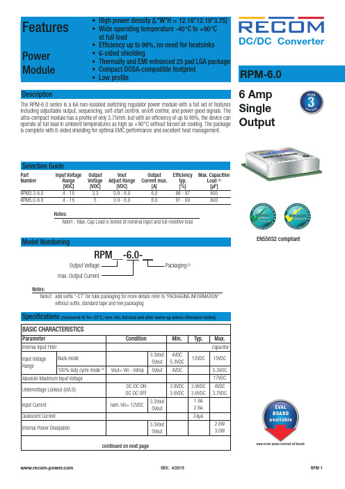
DC/DC Converter/eval-ref-boardsDescriptionThe RPM-6.0 series is a 6A non-isolated switching regulator power module with a full set of features including adjustable output, sequencing, soft-start control, on/off control, and power good signals. The ultra-compact module has a profile of only 3.75mm, but with an efficiency of up to 99%, the device can operate at full load in ambient temperatures as high as +90°C without forced air cooling. The package is complete with 6-sided shielding for optimal EMC performance and excellent heat management.6 Amp Single OutputRPM-6.0FeaturesPower ModuleNotes:Note1: Max. Cap Load is tested at nominal input and full resistive loadModel NumberingSelection GuidePart Input Voltage Output Vout Output Efficiency Max. Capacitive Number Range Voltage Adjust Range Current max. typ. Load (1) [VDC] [VDC] [VDC] [A] [%] [µF]RPM3.3-6.0 4 - 15 3.3 0.9 - 6.0 6.0 88 - 97 800RPM5.0-6.04 - 15 5 0.9 - 6.0 6.0 91 - 99 800Specifications (measured @ Ta= 25°C, nom. Vin, full load and after warm-up unless otherwise stated)BASIC CHARACTERISTICSParameterCondition Min.Typ.Max.Internal Input Filter capacitor Input Voltage RangeBuck mode3.3Vout 5Vout 4VDC 5.3VDC 12VDC15VDC 100% duty cycle mode (3)Vout= Vin - Vdrop5Vout4VDC 5.3VDC Absolute Maximum Input Voltage 17VDC Undervoltage Lockout (UVLO)DC-DC ON DC-DC OFF 3.8VDC 3.5VDC3.9VDC 3.6VDC 4VDC 3.7VDCInput Current nom. Vin= 12VDC3.3Vout 5Vout 1.9A 2.8A Quiescent Current 24µAInternal Power Dissipation3.3Vout 5Vout2.8W3.0Wcontinued on next pageNotes:Note2: add suffix “-CT” for tube packaging for more details refer to “PACKAGING INFORMATION“ without suffix, standard tape and reel packagingPackaging (2)Output Voltagemax. Output CurrentRPM__-6.0-__EN55032 compliantSpecifications (measured @ Ta= 25°C, nom. Vin, full load and after warm-up unless otherwise stated)Specifications (measured @ Ta= 25°C, nom. Vin, full load and after warm-up unless otherwise stated)Specifications (measured @ Ta= 25°C, nom. Vin, full load and after warm-up unless otherwise stated)REGULATIONSParameterCondition ValueOutput Accuracy ±3.0% max.Line Regulation low line to high line, full load0.5% typ. / ±3.0% max.Load Regulation 0% to 100% load1.0% typ. / 3.0% max.Soft-Start Time refer to soft-start capacitor calculationTransient Response100% - 10% load steprecovery time 200mV max. 6ms typ.25% load step changerecovery time 150mV max.500µs typ.continued on next pageSequencing Multiple ModulesThe SEQ pin can be used to program the rising edge of the output voltage. An internal current source charges a soft-start capacitor which is connected from the sequencing pin to GND. The following equation is used to calculate the soft-start capacitor:C ss = soft-start capacitor I ss = sum of all soft-start currents of all sequenced modules t ss = required soft-start time n = number of RPMsI ss [µA]Preset soft-start time [µs]Min.Typ.Max.Min.Typ. Max.4.55.05.5750825920Note: there is a 3.3nF internal soft-start capacitor, and there are different constant current sources in the modules which leads to different preset soft-start times.C ss =t ss x I ss- n x 3.3nF1.25VSpecifications (measured @ Ta= 25°C, nom. Vin, full load and after warm-up unless otherwise stated)Specifications (measured @ Ta= 25°C, nom. Vin, full load and after warm-up unless otherwise stated)PROTECTIONSParameterConditionValueShort Circuit Protection (SCP)50m W hiccup mode, automatic recoveryShort Circuit Input Current without soft-start mode 150mA typ.Over Current Protection (OCP)with soft-start mode110% - 115%, hiccup mode Over Temperature Protection (OTP)case temperature (measured on tc point)DC-DC OFF DC-DC ON110°C, auto restart after cool down100°C typ.Specifications (measured @ Ta= 25°C, nom. Vin, full load and after warm-up unless otherwise stated)DIMENSION AND PHYSICAL CHARACTERISTICSParameter Type ValueMaterialcasePCBsolder padsmetalFR4, (UL94 V-0)copper with electrolytic nickel-goldDimension (LxWxH)12.19 x 12.19 x 3.75mm Weight 1.1g typ.continued on next pageSpecifications (measured @ Ta= 25°C, nom. Vin, full load and after warm-up unless otherwise stated)Specifications (measured @ Ta= 25°C, nom. Vin, full load and after warm-up unless otherwise stated)PACKAGING INFORMATIONParameter Type ValuePackaging Dimension (LxWxH)tape and reeltape and reel (carton)330.2 x 330.2 x 30.4mm355.0 x 350.0 x 50.0mm tube (“-CT”)530.0 x 30.3 x 19.2mmPackaging Quantity tape and reel500pcs tube (“-CT”)30pcsTape Width24mm Storage Temperature Range-55°C to +125°C Storage Humidity non-condensing95% RH max.The product information and specifications may be subject to changes even without prior written notice.The product has been designed for various applications; its suitability lies in the responsibility of each customer. The products are not authorized for use in safety-critical applications without RECOM’s explicit written consent. A safety-critical application is an application where a failure may reasonably be expected to endanger or cause loss of life, inflict bodily harm or damage property. The applicant shall indemnify and hold harmless RECOM, its affiliated companies and its representatives against any damage claims in connection with the unauthorizeduse of RECOM products in such safety-critical applications.。
超特克 DSFP-VN0606 增强模式电源管说明书

Supertex inc.VN0606YY = Year Sealed WW = Week Sealed= “Green” PackagingSi VN 0606L YYWW Features►Free from secondary breakdown ►Low power drive requirement ►Ease of paralleling►Low C ISS and fast switching speeds ►Excellent thermal stability ►Integral source-drain diode►High input impedance and high gainApplications►Motor controls ►Converters ►Amplifiers ►Switches►Power supply circuits►Drivers (relays, hammers, solenoids, lamps, memories, displays, bipolar transistors, etc.)General DescriptionThis enhancement-mode (normally-off) transistor utilizes a vertical DMOS structure and Supertex’s well-proven, silicon-gate manufacturing process. This combination produces a device with the power handling capabilities of bipolar transistors and the high input impedance and positive temperature coefficient inherent in MOS devices. Characteristic of all MOS structures, this device is free from thermal runaway and thermally-induced secondary breakdown.Supertex’s vertical DMOS FETs are ideally suited to a wide range of switching and amplifying applications where very low threshold voltage, high breakdown voltage, high input impedance, low input capacitance, and fast switching speeds are desired.N-Channel Enhancement-ModeVertical DMOS FEToccur. Functional operation under these conditions is not implied. Continuous operation of the device at the absolute rating level may affect device reliability. All voltages are referenced to device ground.TO-92Product MarkingPackage may or may not include the following marks: Si orPin ConfigurationTO-92GATESOURCEDRAINContact factory for Wafer / Die availablity.Devices in Wafer / Die form are lead (Pb)-free / RoHS compliant.OSwitching Waveforms and Test CircuitOUTPUTINPUTOUTPUT10VVDD0V0V1. All D.C. parameters 100% tested at 25O C unless otherwise stated. (Pulse test: 300µs pulse, 2% duty cycle.)2. All A.C. parameters sample tested.† I D (continuous) is limited by max rated T j .Supertex inc. does not recommend the use of its products in life support applications, and will not knowingly sell them for use in such applications unless it receives an adequate “product liability indemnification insurance agreement.” Supertex inc. does not assume responsibility for use of devices described, and limits its liability to the replacement of the devices determined defective due to workmanship. No responsibility is assumed for possible omissions and inaccuracies. Circuitry and specifications are subject to change without notice. For the latest product specifications refer to the Supertex inc. (website: http//)©2013 Supertex inc. All rights reserved. Unauthorized use or reproduction is prohibited.Supertex inc.(The package drawing(s) in this data sheet may not reflect the most current specifications. For the latest package outline information go to /packaging.html .)3-Lead TO-92 Package Outline (L)JEDEC Registration TO-92.* This dimension is not specified in the JEDEC drawing.† This dimension differs from the JEDEC drawing.Drawings not to scale.Supertex Doc.#: DSPD-3TO92N3, Version E041009.。
SPD基础及参数(精编文档).doc
【最新整理,下载后即可编辑】电涌保护器SPD电涌保护器surge protective device (SPD) 指目的在于限制瞬态过电压和分走电涌电流的器件。
它至少含有一个非线性元件,过去常称为“避雷器”或“过电压保护器”。
电涌(又称浪涌)和峰值电压电涌和峰值电压(脉冲)是指“常规”电压的增加,通常由剧烈变动或电力需求的增加而引起。
打开大功率电器、吸尘器、空调、洗衣机都可以引发电涌和峰值电压。
任何一种类型的干扰都能够损坏电子设备。
超出实际维修范围。
另外,恶劣天气(闪电)和电力公司的日常拉关闸及维修工作都会给电源线带来破坏性的电涌。
为什么需要电涌保护器?即使是很小的电涌或峰值电压也可以最终摧毁或影响昂贵的电子设备的性能,如电脑、电话、传真、电视、音频/视频设备和其它家用电器和工具。
电脑芯片的普遍使用越发需要电涌保护,因为这些芯片往往对电压波动都十分敏感。
电涌保护器如何工作电涌保护器像电力海绵一样,能够吸收危险的额外电压,防止大多数这样的电压进入您的敏感设备。
具有电话线保护功能的防涌插座可给您的用电设备提供最完备的保护,以防受到有害电涌侵害。
电涌和尖峰电压会通过电话和电源线破坏或降低您贵重电子设备的性能水平。
完善的电涌保护功能可随时保护诸如计算机、电话机、调制解调器、电视机及其它家庭电子设备和电器用具。
防浪涌插座,可以使您的用电设备及电话设备防雷击、稳定工作、延长电器使用寿命。
产品特点:保护电话/DSL/宽带线路保护高达45,000安的最大尖峰电流提供高达1780焦耳能级的最大保护过滤电磁/无线电频率干扰(EMI/RFI)在1纳秒内响应以保护设备电涌保护器电涌保护器(Surge protection Device)是电子设备雷电防护中不可缺少的一种装置,过去常称为“避雷器”或“过电压保护器”英文简写为SPD。
电涌保护器的作用是把窜入电力线、信号传输线的瞬时过电压限制在设备或系统所能承受的电压范围内,或将强大的雷电流泄流入地,保护被保护的设备或系统不受冲击而损坏。
浪涌保护器(SPD)保护模式详解

浪涌保护器(SPD)保护模式详解浪涌保护器( SPD )保护模式详解——瑞隆源电子一、SPD保护模式的定义用以限制瞬时过电压和泄放电涌电流的电器,它至少应包括一种非线性元件。
在一般平时的工作中也称“浪涌保护器”、“浪涌防护器”、“电涌保护器”、“防雷器”等。
二、浪涌保护器的保护模式1.什么是保护模式:SPD可连接在L(相线)、N(中性线)、PE(保护线)间,如L-L、L-N、L-PE、N-PE,这些连接方式称为保护模式,它们与供电系统的接地型式有关。
按GB50054-95《低压配电设计规范》规定,供电系统的接地型式可分为:TN-S 系统(三相五线)、TN-C系统(三相四线)TN-C-S系统(由三相四线改为三相五线)、IT系统(三相三线)和TT系统(三相四线,电源有一点与地直接连接,负荷侧电气装置外露可导电部分连接的接地极与电源接地极无电气联系)。
目前,浪涌保护器的保护模式大部分是4个保护模式(L-PE,N-PE),即三根火线分别与保护线,中性线与保护线连接。
4模式保护,见图1的最右边的4个模式。
还有一部分是全模式(L-L、L-N、L-PE、N-PE),即三根火线之间,三根火线分别与保护线,三根火线分别与中性线,中性线与保护线。
全模式最多有10模式,在常用的3相星形接地方式中就是10模式。
2.全模保护的浪涌保护器的结构:深圳市瑞隆源电子有限公司专业制作各种不同规格的陶瓷气体放电管,放电管,防雷器,避雷器等等。
TEL=0755********在我国通常使用的4模式保护器中(参照IEC标准),常用的是4个单片组合在一起,三个单片分别连接火线与保护线(L1-G,L2-G,L3-G)另一个单片连接中性线与保护线(N-G)。
4模式的浪涌保护设备没有对浪涌电流经过的所有可能的线路都进行保护,如火线—火线之间(L1-L2,L1-L3,L2-L3),火线—中性线(L1-N,L2-N,L3-N)。
而北美电气电子工程师学会(IEEE)对电涌保护设备有明确规定:用于3相4线+地电路的电涌保护设备需要对电流经过的所有可能的线路进行保护,它们包括L-L,L-N,L-G,N-G。
SPD基础及参数

S P D基础及参数Company Document number:WTUT-WT88Y-W8BBGB-BWYTT-19998电涌保护器SPD电涌保护器surge protective device (SPD) 指目的在于限制瞬态过电压和分走电涌电流的器件。
它至少含有一个非线性元件,过去常称为“避雷器”或“过电压保护器”。
电涌(又称浪涌)和峰值电压电涌和峰值电压(脉冲)是指“常规”电压的增加,通常由剧烈变动或电力需求的增加而引起。
打开大功率电器、吸尘器、空调、洗衣机都可以引发电涌和峰值电压。
任何一种类型的干扰都能够损坏电子设备。
超出实际维修范围。
另外,恶劣天气(闪电)和电力公司的日常拉关闸及维修工作都会给电源线带来破坏性的电涌。
为什么需要电涌保护器即使是很小的电涌或峰值电压也可以最终摧毁或影响昂贵的电子设备的性能,如电脑、电话、传真、电视、音频/视频设备和其它家用电器和工具。
电脑芯片的普遍使用越发需要电涌保护,因为这些芯片往往对电压波动都十分敏感。
电涌保护器如何工作电涌保护器像电力海绵一样,能够吸收危险的额外电压,防止大多数这样的电压进入您的敏感设备。
具有电话线保护功能的防涌插座可给您的用电设备提供最完备的保护,以防受到有害电涌侵害。
电涌和尖峰电压会通过电话和电源线破坏或降低您贵重电子设备的性能水平。
完善的电涌保护功能可随时保护诸如计算机、电话机、调制解调器、电视机及其它家庭电子设备和电器用具。
防浪涌插座,可以使您的用电设备及电话设备防雷击、稳定工作、延长电器使用寿命。
产品特点:保护电话/DSL/宽带线路保护高达45,000安的最大尖峰电流提供高达1780焦耳能级的最大保护过滤电磁/无线电频率干扰(EMI/RFI)在1纳秒内响应以保护设备电涌保护器电涌保护器(Surge protection Device)是电子设备雷电防护中不可缺少的一种装置,过去常称为“避雷器”或“过电压保护器”英文简写为SPD。
领酸智能快充器(6A)用户手册说明书

User ManualOfLead Acid Smart Fast Charger (6 A) for 24V Lead Acid Battery 6Ah- 60Ah (110V Only)AA Portable Power Corp ()Address: 860 S, 19th St, Unit A, Richmond, CA, 94804Tel: 510-525-2328Fax: 510-439-2808Email:**********************Prepared & Approved by Louis (01/10/08)IntroductionAA Portable Power Corp () specialized in the research & Development of the intelligence battery charger in the long terms.The series battery charger is based on MCU technology, with pulse charging mode,the charging voltage has temperature compensation automatically .It could be used in the various electric cars the field of tourism, railway, mine, post and telecommunication .Main Featurez INPUTAC input voltage 90 to 130 VAC , single phaseInput frequency 47 to 63 HzEfficiency 72%(min)at rating power,115Vac 60Hz z OUTPUTCCCV charging modeCut-off voltage: 29.6VDC6 A current Max.Charge terminal: 14AWG wire Standard female Tamiya plug.Do not detach Standard female Tamiya plug from charger Included one pcs connector adaptor, convert from Standard Male Tamiya plug to alligator ClipMust plug Standard Male Tamiya end to the Standard Female Tamiya plug of the charger with correct polarity.Must plug Clip end to the connector of the battery pack with correct polarityz Red Clip = Positivesz Black Clip = NegativeWarning: Wrong polarity will damage the charger, and are not responsible for the damageor losses caused by misusingz CHARGEThe Battery range is between 6AH to 60AHReverse Polarity ProtectionShort Circuit ProtectionNo trigger voltage requirementz Included 1 pcs replacement 5A 250V fusez Built in cooling fan to ensure charger long service lifez Dimension (LxWxH): 174mm(6.8") x 138mm(5.4") x 67mm(2.6")z Weight: 3.0lb (1361 grams)How to use1. Turn on : Make sure the pack voltage is suitable for charger. Then connect to the pack with correct polarity.2. Check the voltage of the AC input is suitable for the input voltage of the charger or not.3 The charger start ramp charging after auto-testing in 1 minute4. Indicating LED signification5. Power indicating and battery test LED:Green LED = Fully charged / Correct Polarity ConnectionRed LED = Charging / Wrong polarity ConnectionOrange LED = 90% fully charged.6. Turn off: After Battery is fully charged, must disconnect the AC power supply before disconnect batteryOperation environmentAbove the sea-level≤2000m.Ambient temperature -10℃~50℃Ambient humidity 5%~70%RHStorage temperature -10℃~60℃Without conductive dustWithout explosive dustWithout corrosive gas and steam damaged to metal and isolatorkeep away from rain and snowMounting slop ≤5 degreeMaintenance and serviceThe charger must be set at ventilated, dry and dust-less place to prevent the reduction of the performance of the charger.For technical support, please contact us via **********************.。
EATON 保护设备,微型断路器 PLG6 型号说明书

Protective DevicesMiniature Circuit Breakers PLG6, N-leftX.X• T op-quality miniature circuit breakers 1P+N with a width of 1 module unit requiring little space for installation• Contact position indicator red - green • Guide for secure terminal connection • C omprehensive range of accessories for sub-sequent installation • Rated currents up to 40 A • Tripping characteristics B, C• R ated breaking capacity 6 kA according to IEC/EN 60898DescriptionSG11811X.X Protective DevicesMiniature Circuit Breakers PLG6, N-leftRated current I n (A)TypeDesignationArticle No.Units perpackage6 kA, Characteristic BSG118116PLG6-B6/1N26467212/12010PLG6-B10/1N26467312/12013PLG6-B13/1N26467412/12016PLG6-B16/1N26467512/12020PLG6-B20/1N26467612/12025PLG6-B25/1N26467712/12032PLG6-B32/1N26467812/12040PLG6-B40/1N26467912/1201+N-pole6 kA, Characteristic CSG118112PLG6-C2/1N26469012/1204PLG6-C4/1N26469112/1206PLG6-C6/1N26469212/12010PLG6-C10/1N26469312/12013PLG6-C13/1N26469412/12016PLG6-C16/1N26469512/12020PLG6-C20/1N26469612/12025PLG6-C25/1N26469712/12032PLG6-C32/1N26469812/12040PLG6-C40/1N26469912/1201+N-poleX.XProtective DevicesMiniature Circuit Breakers PLG - T echnical DataSpecifi cations | Miniature Circuit Breakers PLGDescription• H igh selectivity between MCB and back-up fuse due to low let-through energy• P rofi le compatible with other devices of the Xpole series, bridging with thePFGM RCD circuit breaker is possible• C olour of the switching toggle according to the performance rating of thecircuit breaker• M eets the requirements of insulation co-ordination, distance between con-tacts > 4 mm, for secure isolation• Rated breaking capacity I cn1 = 3 kA• N-LinksTechnical DataPLGElectricalIEC/EN 60898Design according toCurrent test marks as printed onto the deviceRated voltage U nAC230 VDC48 VRated frequency50/60 HzRated breaking capacityPLG6 6 kAPLG4 4.5 kACharacteristic B, CBack-up fuse>6 kA max. 100 A gL/gG>4.5 kA max. 80 A gL/gGSelectivity class3Endurance electrical components 8,000 operating cyclesMechanicalFrame size45 mmDevice height80 mmDevice width 17.5 mm per pole (1MU for 1p+N)Mounting quick fastening with 2 lock-in positions on DIN rail EN50022 Degree of protection IP20Upper and lower terminals open mouthed/lift terminalsTerminal protection fi nger and hand touch safe, DGUV VS3, EN 50274 Terminal capacity1x (1.5 - 35) mm2 single wire2x (1.5 - 16) mm2 multi wireTerminal cross-section1-16 mm2Connection diagram1-pole + NDimensions (mm)X.XProtective DevicesMiniature Circuit Breakers PLG - T echnical DataLoad rating – Effect of ambient temperature PLG6Permitted permanent load at ambient temperature T (°C) with n devices I DL = I n K T (T) K N (N)Let-through energy PLG6Let-through energy PLG6, Characteristic B, 1+N-poleLet-through energy PLG6, Characteristic C, 1+N-poleLoad Capacity of Series Connected PLG6Effect of ambient temperature (I n = 2-13 A)Effect of ambient temperature (I n = 32, 40 A)Effect of ambient temperature ( I n= 16-25 A)L o a d c a p a c i t y K T [I /I n ]L o a d c a p a c i t y K T [I /I n ]L o a d c a p a c i t y K T [I /I n ]L e t t h r o u g h e n e r g y I 2t [A 2 s e c ]Prospective short-circuit current [A]L e t t h r o u g h e n e r g y I 2t [A 2 s e c ]Prospective short-circuit current [A]L o a d c a p a c i t y f a c t o r K NNumber of devices (n)Ambient temperature T [°C]Protective DevicesMiniature Circuit Breakers PLG - T echnical DataX.XLoad rating – Effect of ambient temperature PLG4Permitted permanent load at ambient temperature T (°C) with n devices I DL = I n K T (T) K N (N)Let-through energy PLG4Let-through energy PLG4, Characteristic B, 1+N-poleLet-through energy PLG4, Characteristic C, 1+N-poleLoad Capacity of Series Connected PLG4Effect of ambient temperature (I n = 2-13 A)Effect of ambient temperature (I n = 32, 40 A)Effect of ambient temperature ( I n= 16-25 A)500300500100015002000300040005000600070001000015000800090004009007008006001500100030002000500040002000090007000100008000600015000300005000060000400007000080000prospektiver Kurzschlußstrom [A]D u r c h l a ße n e r g i e I t [A s e c ]22prospektiver Kurzschlußstrom [A]D u r c h l a ße n e r g i e I t [As e c ]22500300500100015002000300040005000600070001000015000800090004009007008006001500100030002000500040002000090007000100008000600015000300005000060000400007000080000L e t t h r o u g h e n e r g y I 2t [A 2 s e c ]Prospective short-circuit current [A]L e t t h r o u g h e n e r g y I 2t [A 2 s e c ]Prospective short-circuit current [A]L o a d c a p a c i t y f a c t o r K NNumber of devices (n)L o a d c a p a c i t y K T [I /I n ]L o a d c a p a c i t y K T [I /I n ]L o a d c a p a c i t y K T [I /I n ]Ambient temperature T [°C]。
基站电源防雷器(SPD)接线方式

3.3.2 在直流配电系统中分为正极与负极(V+-V-)、正极与 地线(V+-PE)、负极与地线(V--PE)之间等三种保护模式。
注:限压型SPD和具有限压特性的组合型SPD可用于任一保护模式。电压开关型SPD和具有 开关特性的组合型SPD因存 在尚待进一步研究的续流遮断能力及其试验方法问题,不宜在除N-PE外的其它保护模 式中推广使用
是防雷箱的残压。
➢假设通过防雷箱的雷电流为20KA:
➢防雷箱的残压为1500V
➢L1的残压=L1*di/dt=1uH*20KA/10uS=2KV
➢L2的残压=L2*di/dt=5uH*20KA/10uS=10KV
➢则最终开关电源交流输入侧得到的剩余电压(残压)=2+1.5+10KV=13.5KV。
➢远远大于防雷箱的1500V电压,也远远超过开关电源2500V的耐压,结果失去了防雷的保护效果,
基站电源(380V/220V)防雷器 (SPD)接线方式
2021/10/10
1
防雷器图例及接线方式要求
局站防雷接地设计5098-2005第9.2.4条规定 局20站21防/10雷/10接地设计5098-2005第9.2.7条规定,凯文接线会造成供电系统中断要慎用 2
什么是SPD(SPD介述)
▪ SPD这一名词英语全称是surge protectiye device其译意为电涌保护器,是限制雷电反 击、侵入波、雷电感应和操作过电压而产生的瞬时过电压和泄放电涌电流(沿线路传 送的电流、电压或功率的暂态波。其特性是先快速上升后缓慢下降)的器件。
b) 另一种是TT系统,对于TT系统供电方式必须选用3+1模式 的SPD。
以上内容在《通信局站在用防雷系统技术要求和检测方法》 中已经给予了详细讲解,因此不再赘述。
浪涌保护器(SPD)与过电流保护器的配合使用

为 防 止S P D的失 效故 障 , S P D 前 端应 安 装熔 丝 或 热熔 断器 等过 电流保 护 器。 其前端过 电流保护器的保险电流值与主电路上过电流保护器的保险电流值 不宜小 于1 : 1 . 6 1 4 1 。 S P D失效模 式为短 路 时 , 可 能会 影响受 保护 系统和 设备 的正
流变大 时 , 温度 逐 渐升 高 还会 引发 火灾 。 2 - S P D 和低 压 短路 保 护器 件 的原 理
2 1 S P D 、 空气 型 断路器 、 熔 断器 的工 作 原理
达到 了过 电流保护 器 的响应 时间t 3 , l  ̄ l l t l + t 2 >t 3 , 则过 电流保护器 可 能会动作 。 而过 电压 的泄流 时间与S P D 的泄 流 阻抗Z 1 和 过 电流保 护器 的泄流 阻抗z 2 有关 .
内, 是建 筑防 雷工作 中必不 可少 的一部分 。 按 工作 原理分 为限压 型浪涌 保护器 、 组合 型 浪涌 保护 器 、 电压 开 关 型浪涌 保 护器 。 空气型 断路器是 低压配 电系统 中最常 使用 的低压 断路器 。 它 的三 个触头 串 联 在 三相 主 电路 中 , 电磁脱 扣器 的线 圈及 热脱 扣器 的热元 件 与主 电路 串联 , 欠 电压 脱扣器 线圈与 主 电路并联 。 当 断路器 闭合 后, 三个 主触 头保持 闭合状 态 。 当 电磁 脱扣器 吸合 或热脱 扣器 的双 金属 片受 热弯 曲或欠 电压 脱扣器 释放 , 这 三者
短 路情 况 。 5 . 1开 关型S P D  ̄ n 限压型 S P D 的缺 陷
器 线 圈产生 的 电磁 力不 能将磁铁 吸合 , 而 当 电路 发生短 路 , 出现很 大过 电流时 , 主触 头断开 , 切 断主 电路 , 若 电路 发生过 载 , 但又达 不到 电磁脱 扣器动 作的 电流 时, 触头分 开来断 开 电路 , 起 到过 载保护 作用 , 若 电源 电压 下 降较多或 失去 电压 时, 同样 导致 触头 断开 而切断 电路 , 起到 欠 电压 或失 电压 保护 作用 。 空气 开关 是 低 压 断路器 的其 中一种 , 它是 一种 只要 有短 路 形成 回路 就会 跳 闸的 开关 。 熔 断器 是一种结构简单 、 使 用方便 、 价格 低廉的起保护作用 的电器 , 它 串联 在 被保 护电路中 , 当线路或 电气设备 的电流 超过规定值足够长的时间后 , 其 自身产 生 的热量 能够熔断一个 或几个特殊 设计的和相应 的部件 , 断开其所接人 的 电路并分 断 电源 , 从 而起 到保护作 用[ 1 】 熔 断器广 泛应用于 高低压 配 电系统 和控制 系统 以 及用 电设备 中 , 作为 短路和 过电流的保 护器 , 是应用最 普遍的保 护器件之一 。 3 S P D 串联 过 电流 保 护器 的 作 用 S P D 通常 并联 或 串联 安装在 被保 护设备 端 。 当瞬 态 电涌未 到 时, 呈 高阻态 , 被 保护 电路 正常 工作 , 当瞬态 电涌 到来 时 , 迅速 转变 为低 阻态 , 电涌 电流旁路 ,
浪涌保护器(SPD)的选择和使用

选择和使用规范
向石 IEC/TC81/WG3 中国专家 E—mial:xiangdeboo@
雷击类型、损害和损失类型
建筑物 雷击点 损害 来源 S1 损害 类型 D1 D2 D3 损失类型 L1,L4b L1,L2,L3,L4 L1,L2,L4 公共设施 损害 类型 D2 D3 损失 类型
Insulation coordination 绝缘区域协调 acc. to DIN VDE 0110 part 1
雷击放电器
L1 L2 L3 PEN 过电压放电器 仪器保护
kWh Z
主配电6 kV 绝缘区域的抗冲击电压强度
二次配电4 kV 2,5 kV
用电器1,5 kV
SPD在TN-C-S系统中安装
带有绝缘监测装置的IT-System
电力公司 主配电 二次配电 用电器
L1 L2 L3 PE
Z<
FLASHTRAB VALVETRAB
仪器保护
SPD在TT中安装
电涌保护器(SPD)安装在TT系统中剩余电流 保护器(RCD)的负荷侧
按系统特征确定的电涌保护器的连接形式
电涌保护器安装点的系统型式 TT系统 电涌保护 器 接于 装设依据 接线 形式1 每一相线和 中性线间 每一相线和 PE线间 中性线和PE 线间 每一相线和 PEN线间 相线间 (L-L间) + · · 接线 形式2 · 不适用 · 不适用 不适用 不适用 · + TN-S系统 引出中性线的IT系统 装设依据 接线 形式1 + · · 不适用 + 接线 形式2 · 不适用 · 不适用 + 不引出 中性线 的IT系 统 不适用 · 不适用 不适用 +
杰弗逊电器 SA-OWSP60 6口旋转插座防雷保护器说明书

When the LED INDICATOR no longer lights up, the surge protection has been exhausted and it’s time to replace the u nit!CAUTION!: Avoid potential personal injuries and property damage!• To Reduce the Risk of Electric Shock - Use Only in Dry Locations, Indoors!• Ensure all of your external connections, including Satellite/Cable TV (Coax) and Phone/Ethernet (RJ45), are protected if applicable. Transient lines connected directly to your equipment without first passing through a surge protector are at risk of damage and are not covered by the connected equipment warranty.• Due to the sacrificial properties of the internal MOV’s it is recommended that the surge protector be checked after lightning storms to verify the surge protection was not consumed.• The input plug of this power tap is intended to serve as the disconnect device, it shall be easily accessible and withdrawn.• This power center does not contain internal circuit breaker protection. INSTALLER MUST ensure that the input of this power center is connected individually to an electrical service panel that is protected with a UL Listed 20A (Maximum) circuit breaker for overload protection of the power center.• Not designed for use with receptacles with indicator lights or controls as this unit will cover them.• To reduce the risk of fire or electric shock, do not use this device with a receptacle in which the slot openings to not align with the blades.• All accessories must be grounded.• Circuit Overloading - Consideration should be given to the connection of the equipment to the supply circuit and the effect that overloading of the circuits might have on overcurrent protection and supply wiring. Appropriate consideration of equipment nameplate ratings should be used when addressing this concern.• Surge protector must be plugged directly to the power source and must not be "daisy-chained" together (in serial) with other power strips, surge protectors or extension cords.• Do not use this product for any purpose not explicitly specified by manufacturer.• If you do not understand these instructions, or have doubts about the safety of the installation, assembly or use of this product, contact Customer Service or call a qualified contractor.• Do not disassemble the surge protector. Disassembling will void the warranty and may cause serious personal injury.• Manufacturer is not responsible for damage or injury caused by incorrect assembly or use.LEGRAND LIMITED WARRANTY AND CONNECTED EQUIPMENT DAMAGE LIMITED WARRANTYProduct WarrantyLegrand warrants to the original purchaser that the product shall be free of defects in materials and workmanship under normal use for five (5) years. When this surge protector operates properly and prevents an energy surge from damaging electrical equipment, the surge protective component will disconnect from the circuit and you will need to buy a replacement product. This warranty extends only to the original purchaser and is nontransferable during the warranty period. Legrand will, at no additional charge, repair or replace defective parts or, at its option, replace the entire unit. This warranty does not extend to any Legrand product that has been damaged or rendered inoperable as intended or defective (a) as a result of accident, misuse or abuse; or (b) by the use of parts not manufactured or sold by Legrand; or (c) by modification of the product.Connected Equipment Damage Limited WarrantyLegrand will also provide you with a remedy for damage to connected equipment if (i) you have a claim that is covered by the limited product warranty described above, and (ii) Legrand receives a formal warranty claim from you before the end of the warranty period for damage to connected applicable to the affected product. If the conditions listed in the preceding sentence are met, Legrand will provide you with one of the following remedies, provided that it may decide at its sole discretion which remedy it provides. Legrand will (1) replace the damaged connected equipment; (2) pay to repair the damaged connected equipment; or (3) pay you the fair market value of the connected equipment, provided that such payments shall not exceed (i) the maximum coverage amount for the product, or (ii) the amount of actual damage caused by power surges due to a product defect. NOTE: Compensation for restoration of data loss is not covered AND LEGRAND DOES NOT ASSUME ANY LIABILITY FOR ANY LOSS OF PROFIT , REVENUE OR SAVING (WHETHER DIRECT OR INDIRECT) OR FOR ANY INCIDENT AL, CONSEQUENTIAL OR INDIRECT DAMAGES UNDER THIS LIMITED WARRANTY . Protection for Network/T elephone (RJ45) or Cable/Satellite TV (CA TV Coax) transient lines only applies to Legrand products which offer such protection, and in such cases, the connections must be properly installed and CA TV service must be grounded properly according to codes set forth in the National Electric Code (NEC) in order to be covered. Some states do not allow the exclusion or limitation of incidental or consequential damages, so the above limitation or exclusion may not apply to you. THE MAXIMUM AMOUNT OF COVERAGE FOR DAMAGE TO PROPERLY CONNECTED EQUIPMENT IS $25,000. Nothing in this warranty shall exclude or limit liability for death or personal injury caused by negligence, for fraud or fraudulent misrepresentation or where exclusion or limitation is not permitted by law.Other Rights. THESE LIMITED WARRANTIES GIVE YOU SPECIFIC LEGAL RIGHTS, AND YOU MAY ALSO HAVE OTHER RIGHTS. THIS WARRANTY DOES NOT AFFECT YOUR STATUTORY RIGHTS. THIS WARRAN TY EXTEN DS ON LY TO YOU, THE ORIGIN AL PURCHASER, AN D CAN N OT BE TRAN SFERRED OR ASSIGN ED. If any provision of these limited warranties is unlawful, void or unenforceable, that provision shall be deemed severable and shall not affect any remaining provisions. In case of any inconsistency between the English and other versions of these limited warranties, the English version shall prevail.Registration. Please register your Product at . Failure to register does not affect your warranty rights.FORMAL WARRANTY CLAIMHow To Make A Claim. In the event damage has occurred to a Legrand product or to connected equipment, you must contact Legrand within thirty (30) days of the date you knew or should have known of the damages. Follow all instructions for making a claim. THIS REQUIREMENT THAT YOU NOTIFY LEGRAND WITHIN THIRTY (30) DAYS AFTER YOU DISCOVER OR SHOULD HAVE DISCOVERED A PRODUCT DEFECT AFFECTS AND LIMITS YOUR WARRANTY RIGHTS.GENERAL PROVISIONSChoice of Law/Jurisdiction. These limited warranties and any disputes arising out of or in connection with these limited warranties (“Disputes”) shall be governed by the laws of England and Wales, excluding the Convention for the International Sale of Goods. The courts located in England and Wales shall have exclusive jurisdiction over any Disputes.TO THE MAXIMUM EXTENT PERMITTED BY LAW THESE LIMITED WARRANTIES ARE IN LIEU OF AND IN PLACE OF ALL OTHER EXPRESS OR IMPLIED WARRANTIES, CONDITIONS AND OTHER TERMS.Legrand AV Inc. and its affiliated corporations and subsidiaries (collectively, “Legrand”), intend to make this manual accurate and complete. However, Legrand makes no claim that the information contained herein covers all details,conditions, or variations. Nor does it provide for every possible contingency in connection with the installation or use of this product. T he information contained in this document is subject to change without notice or obligation of any kind. Legrand makes no representation of warranty, expressed or implied, regarding the information contained herein. Legrand assumes no responsibility for accuracy, completeness or sufficiency of the information contained in this document.©2021 Legrand AV Inc. All Rights Reserved. SANUS is a Legrand AV Inc. brand. SANUS and the SANUS logo are trademarks of Legrand.Legrand A V Inc. • 6436 City West Parkway • Eden Prairie, MN 55344 USAWe’ll Make It Stress-FreeIf you have any questions, just give us a call.800-359-5520。
DZD-6A高密度电法测量系统_仪器使用说明书
DZD—6A 多功能直流电法(激电)仪
使用说明书
中装集团 重庆地质仪器厂
中集集团 重庆地质仪器厂
DZD-6A 多功能直流电法(激电)
目录
一、仪器主要技术指标……………………………………………………1 二、仪器结构………………………………………………………………1 三、操作说明……………………………………………………………2 3—1 开机与对比度的调整………………………………………………2 3—2 简易的操作过程……………………………………………………3 3—3 具体操作步骤………………………………………………………4 四、关于特殊文件(模式)的操作说明……………………………………5 五、仪器的维修和保养…………………………………………………7 附录一:电极排列的说明………………………………………………8 附录二:仪器的成套性…………………………………………………13 附录三:存储数据排列格式……………………………………………14 附录四:装置的电极距选择规则………………………………………15 附录五:操作关键词解释………………………………………………16 附录六:实测曲线………………………………………………………17 6—1 有关绘制实测曲线的说明…………………………………………17 6—2 绘制实测曲线的操作………………………………………………17 6—3 该仪器在做复合四极法和联合剖析面法中的实际运用…………18 6—4 本仪器所设计的装置类型的说明及参数定义……………………19 附录七:问题解答………………………………………………22 附录八: 8—1 找水实例的曲线解释………………………………………………23 8—2 找矿实例……………………………………………………………24 DZD-6A 多功能直流电法(激电)仪装箱单
低压配电系统的电涌保护器(SPD)
低压配电系统的电涌保护器(SPD)第一部分:性能要求和实验方法1总则1.1使用范围GB18802的本部分使用对于间接雷电和直接雷电影响或其他瞬时过电压的电涌进行保护的电器。
这些电器被组装后连接到交流额定电压不超过1000V(有效值)、50/60HZ或直流电压不超过500V的电路和设备。
本部分规定这些电器的性能特性、标准实验方法和额定值,这些电器至少包含一用来限制电涌电压和泄放电涌电流的非线性的原件。
1.2规范性引用文件下列文件中的条款通过GB18802的本部分的引用而成为本部分的条款。
凡是注口期的引用文件,其随后所有的修改单(不包括勘误的内容)或修订版均不适用于本部分,然而,鼓励根据本部分达成协议的各方研究是否可使用这些文件的最新版本。
凡是不注口期的引用文件,其最新版本适用于本部分。
GB2099.1—1996家用和类似用途插头插座第1部分:通用要求(eqvIEC60884-l:1994)GB/T4207-1984固体绝缘材料在潮湿条件下相比漏电器痕指数和耐漏电起痕指数的测定方法(eqvIEC60112:1979)GB4208—1993外壳防护等级(IP代码)(evqIEC60529:1989)GB5013—1997(全部)额定电压450/750V及以下橡皮绝缘电缆(idtIEC620245)GB5203—1997(全部)额定电压450/750V及以下聚氯乙烯绝缘电缆(idtIEC620227)GB/T5169.10—1997电工电子产品着火危险试验试验方法灼热丝试验方法总则(ldtIEC60695-2-1/0:1994)GB10963—1999家用及类似场所涌过电流保护断路器(idi!EC60947-l:1999)GB/T14048.1—2000低压开关设备和控制设备总则(eqvIEC60947-1:1999)GB14048.5-1993低压开关设备和控制设备控制电路电器和开关元件第1部分:机电式控制电路电器(eqvEC609947-5-1:1990)GB/T16927.1—1997高电压试验技术第一部分:一般试验要求:(eqvEEC60060-1:1989)GB/T16935.1—1997低压系统内设备的绝缘配合第一部分:原理、要求和试验(idtIEV60664-1:1992)GB/T17627.1-1998低压电气设备的高电压试验技术第一部分:定义和试验要求(eqvIEC61180-1:1992)IEC60364-4-442:1993建筑物的电气装置第4部分:安全性保护第44章:防过电压保护第442节:防高压系统对地之间故障的低压装置保护IEC60364-4-442::1993建筑物的电气装置第5部分:电气设备的使选用第534节:过电压保护装置IEC60999(全部)连接设备与铜导线电气连接的螺钉和无螺钉夹紧器的安全要求IEC61643-12连接低压配电系统的电涌保护器第12部分:选择和使用原则2使用条件2. 1.1频率:电源的交流频率在48HZ和62HZ之间2. 1.2电压:持续施加在SPD的连接线端子之间的电压不应超过其最大持续工作的电压。
ic65n 3p d6a施耐德小型断路器
ic65n 3p d6a施耐德小型断路器
▲断路器是指能够关合、承载和开断正常回路条件下的电流并能关合、在规定的时间内承载和开断异常回路条件下的电流的开关装置。
断路器按其使用范围分为高压断路器与低压断路器,高低压界线划分比较模糊,一般将3kV以上的称为高压电器。
▲断路器可用来分配电能,不频繁地启动异步电动机,对电源线路及电动机等实行保护,当它们发生严重的过载或者短路及欠压等故障时能自动切断电路,其功能相当于熔断器式开关与过欠热继电器等的组合。
而且在分断故障电流后一般不需要变更零部件。
目前,已获得了广泛的应用。
▲电的产生、输送、使用中,配电是一个极其重要的环节。
配电系统包括变压器和各种高低压电器设备,低压断路器则是一种使用量大面广的电器
▲断路器应垂直安装,且在安装前应先检查断路器铭牌上所列的技术参数是否符合使用要求。
▲通电前应人工操作几次断路器,其机构动作应灵活可靠、无阻滞现象。
▲按下闭合按钮(黑色),电路处于接通状态;按下断开按钮(红色),电路处于断开状态。
▲使用过程中,应对断路器进行定期检查(一般为一个月),即在断路器合闸通电状态下,拨动试验按钮(试验按钮用符号“Test”表示),断路器应可靠断开。
▲当断路器因线路发生过载、短路故障而断开时,应先排除故障后再使断路器重新合闸。
▲本断路器为非维护型,所以当断路器发生故障不能正常工作时,用户不得私自打开断路器进行维修。
▲使用电流调节旋钮,须按线路实际电流调节至相应位置,请勿超负荷使用
▲如需近一步了解施耐德接触器,ABB断路器,西门子接触器,西门子断路器,常熟开关,价格,厂家,批发,参数等。
请关注科旭机电。
电涌保护器(SPD)工作原理和结构及选择及安装

电涌保护器(SPD)工作原理和结构及选择及安装电涌保护器(SPD)工作原理和结构电涌保护器(Surge protection Device)是电子设备雷电防护中不可缺少的一种装置,过去常称为“避雷器”或“过电压保护器”英文简写为SPD.电涌保护器的作用是把窜入电力线、信号传输线的瞬时过电压限制在设备或系统所能承受的电压范围内,或将强大的雷电流泄流入地,保护被保护的设备或系统不受冲击而损坏。
电涌保护器的类型和结构按不同的用途有所不同,但它至少应包含一个非线性电压限制元件。
用于电涌保护器的基本元器件有:放电间隙、充气放电管、压敏电阻、抑制二极管和扼流线圈等。
一、SPD的分类1、按工作原理分:1.开关型:其工作原理是当没有瞬时过电压时呈现为高阻抗,但一旦响应雷电瞬时过电压时,其阻抗就突变为低值,允许雷电流通过。
用作此类装置时器件有:放电间隙、气体放电管、闸流晶体管等。
2.限压型:其工作原理是当没有瞬时过电压时为高阻扰,但随电涌电流和电压的增加其阻抗会不断减小,其电流电压特性为强烈非线性。
用作此类装置的器件有:氧化锌、压敏电阻、抑制二极管、雪崩二极管等。
3.分流型或扼流型分流型:与被保护的设备并联,对雷电脉冲呈现为低阻抗,而对正常工作频率呈现为高阻抗。
扼流型:与被保护的设备串联,对雷电脉冲呈现为高阻抗,而对正常的工作频率呈现为低阻抗。
用作此类装置的器件有:扼流线圈、高通滤波器、低通滤波器、1/4波长短路器等。
按用途分:(1)电源保护器:交流电源保护器、直流电源保护器、开关电源保护器等。
(2)信号保护器:低频信号保护器、高频信号保护器、天馈保护器等。
二、SPD的基本元器件及其工作原理1.放电间隙(又称保护间隙):它一般由暴露在空气中的两根相隔一定间隙的金属棒组成,其中一根金属棒与所需保护设备的电源相线L1或零线(N)相连,另一根金属棒与接地线(PE)相连接,当瞬时过电压袭来时,间隙被击穿,把一部分过电压的电荷引入大地,避免了被保护设备上的电压升高。
浅谈广播电视发射台站防雷接地技术
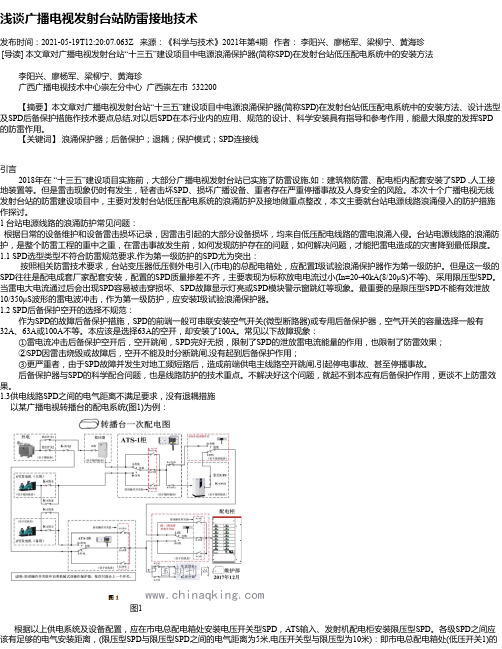
浅谈广播电视发射台站防雷接地技术发布时间:2021-05-19T12:20:07.063Z 来源:《科学与技术》2021年第4期作者:李阳兴、廖杨军、梁柳宁、黄海珍[导读] 本文章对广播电视发射台站“十三五”建设项目中电源浪涌保护器(简称SPD)在发射台站低压配电系统中的安装方法李阳兴、廖杨军、梁柳宁、黄海珍广西广播电视技术中心崇左分中心广西崇左市 532200【摘要】本文章对广播电视发射台站“十三五”建设项目中电源浪涌保护器(简称SPD)在发射台站低压配电系统中的安装方法、设计选型及SPD后备保护措施作技术要点总结,对以后SPD在本行业内的应用、规范的设计、科学安装具有指导和参考作用,能最大限度的发挥SPD 的防雷作用。
【关键词】浪涌保护器;后备保护;退耦;保护模式;SPD连接线引言2018年在 “十三五”建设项目实施前,大部分广播电视发射台站已实施了防雷设施,如:建筑物防雷、配电柜内配套安装了SPD ,人工接地装置等。
但是雷击现象仍时有发生,轻者击坏SPD、损坏广播设备、重者存在严重停播事故及人身安全的风险。
本次十个广播电视无线发射台站的防雷建设项目中,主要对发射台站低压配电系统的浪涌防护及接地做重点整改,本文主要就台站电源线路浪涌侵入的防护措施作探讨。
1 台站电源线路的浪涌防护常见问题:根据日常的设备维护和设备雷击损坏记录,因雷击引起的大部分设备损坏,均来自低压配电线路的雷电浪涌入侵。
台站电源线路的浪涌防护,是整个防雷工程的重中之重,在雷击事故发生前,如何发现防护存在的问题,如何解决问题,才能把雷电造成的灾害降到最低限度。
1.1 SPD选型类型不符合防雷规范要求,作为第一级防护的SPD尤为突出:按照相关防雷技术要求,台站变压器低压侧外电引入(市电)的总配电箱处,应配置I级试验浪涌保护器作为第一级防护。
但是这一级的SPD往往是配电成套厂家配套安装,配置的SPD质量掺差不齐,主要表现为标称放电电流过小(In=20-40kA(8/20μS)不等)、采用限压型SPD。
德特威勒6A类布线系统解决方案

70 系列屏 蔽 双 绞 线 的 线 径 比 6 非 屏 蔽 双 绞 02 类 线 略 细 的 0 5 mm, 它 十分 容 易 弯 曲 . 全 不 会 .7 使 完
4 智 筑与 信息 20 年 第3期 总 2 期 . 4 能建 城市 07 第14
维普资讯
传 输 线 路 全部 隐藏 ”在 铸 造成 型 的屏 蔽 壳体 中 . 使 无 孔 不 入 的 电磁 波 难 以找 到侵 入 的 缝 隙 . 因此 它
面积金 属物 体对非屏 蔽双绞线所 可能产生 的分 布 电容
( 它会 引起衰 减和特 性 阻抗变 化 )在 屏蔽 双绞 线面前 .
都将 无法施 展其 破坏 能 力 , 因此屏 蔽双绞 线在 超高频
维普资讯
■ C嘉 烹
德特威勒6 A类 布 线 系 统
解 决 方 案
着重介 绍双绞 线 、模 块和 配线架 。
输介质。由于材料的限制 。6 A类综合布线系统的物 理带宽定义为 5 0 z 0 MH .远远低于万兆光纤的带宽 值。 但是 . 由于光纤接口设备昂贵。 使双绞线传输技 术仍然走俏 . 这也许就是在数年前推 出万兆光纤技术 电磁 干扰 性 能优 于 常规 的 金属 板 材制 作 的屏 蔽
壳体 。
70 0 2系列屏蔽 自身带有两种介质的屏蔽材料 . 根据电磁理论 .铜网和铝箔分属逆磁材料和顺磁材
对 于 德特威 勒 电缆 系统 ( 上海 ) 有限 公司 ( 以下
近 A 3 规 (.7 m ,这样 细的双 绞线 ,几 WG 2 线 0 53 m) 乎 比绝大 多数 6类非 屏蔽 双绞 线 的线 径都 要 小 。同 时 . 02 70 系列双绞 线 的绝 缘层 采用 了物理 发泡 技术 . 使绝 缘层 的厚 度也 有所 下降 。 最终 , 整根双绞 线 的外
保护它!6口插座防雷保护器,15英尺线,790J,诊断LED,轻灰色外壳说明书

Protect It! 6-Outlet Surge Protector, 15 ft. Cord, 790 Joules, Diagnostic LED, Light Gray Housing MODEL NUMBER:TLP615Safeguard your computer, printer, scanner, router, modem and other small home electronics against dangerous surges, spikes and line noise. Recommended for any desktop, network or home application requiring AC line protection.DescriptionPerfect for your home or office workstation, the TLP615 Protect It!® 6-Outlet Surge Protector features a surge protection rating of 790 joules to defend your sensitive electronic components against strong surges and spikes.Because residential power outlets have three wires—hot line (H), neutral (N) and ground (G)—the TLP615 protects all three, covering the two protection modes: full normal mode (H-N) and common mode (N-G/H-G). It also filters out electromagnetic interference (EMI) and radio frequency interference (RFI) that can disrupt your electronics and inflict hardware damage or data loss.Your devices plug into six NEMA 5-15R outlets, one of which is placed at the end to accept a bulky transformer without blocking adjacent outlets. An integrated 15A circuit breaker protects all outlets and shuts down connected equipment in case of overload. The lighted on/off switch provides one-touch control over connected equipment. A diagnostic LED confirms your connected equipment is protected.The 15-foot (4.8-meter) AC power cord with NEMA 5-15P plug gives you enough flexibility to reach distant outlets while fitting easily into your workstation or home theater setup. Keyhole slots incorporated into the bottom panel provide convenient wall or desk mounting options for the light gray plastic housing.Features790-Joule Surge Protection for Home or Office ElectronicsProtects your computer, printer, scanner, router, modem and other small home electronics against even the strongest surges and spikesqRecommended for any desktop, network or home electronics application requiring AC line protectionqFull normal mode (H-N) and common mode (N-G/H-G) line surge suppressionqFilters out disruptive EMI/RFI line noise that can cause equipment damage or data lossqExceeds IEEE 587 Category A and B surge suppression specificationsq6 Outlets Accept Wide Range of Electronic Devices6 NEMA 5-15R AC outlets accept most computers and peripheralsqSpecial end outlet designed for bulky transformers without blocking other outletsqPremium Safety FeaturesLighted on/off switch provides one-touch control over connected equipmentqAutomatic shutoff permanently cuts power to outlets if protection circuit is incapacitated, preventingq Highlights6 NEMA 5-15R outlets—onedesigned for a bulky transformer q790-joule surge protection rating qFilters out threatening EMI/RFIline noiseq15A resettable circuit breakerprevents dangerous overloads q15 ft. AC power cord with NEMA5-15P plugqPackage IncludesTLP615 Protect It! 6-OutletSurge Protector, Light GrayHousingqOwner’s manualqSpecificationsequipment damage and indicating replacement is requiredDiagnostic LED confirms protection status at a glance q Conforms to current UL 1449 3rd Edition safety standards q ABS fire retardant plastic case provides extra safety and durabilityqFits Effortlessly Into Your Workstation15 ft. AC power cord with NEMA 5-15P plug reaches distant outletsq Keyhole slots on bottom panel provide convenient wall or desk mounting optionsqBacked by Ultimate Lifetime Insurance$20,000 Ultimate Lifetime Insurance covers any connected components damaged by power surge (U.S., Canada and Puerto Rico only)q© 2023 Eaton. All Rights Reserved. Eaton is a registered trademark. All other trademarks are the property of their respective owners.。
SPD-6A-10A串联型防雷器和SPD-6B-10B并联型防雷器介绍

SPD-6A/10A串联型防雷器和SPD-6B/10B并联型防雷器介绍我们照明行业常说的防雷器,专业名称应该是浪涌保护器或突波吸收器。
浪涌也叫突波,就是超出电器正常工作电压的瞬间过电压,维持时间仅百万份之一秒。
浪涌主要有两类来源:一类是来自外界雷电感应,云层与大地之间的雷击放电,闪电电流高达数十、甚至数千安培,强大的雷电流产生的电磁波在电源线或信号线上感应极高的脉冲电压;第二类是来自工厂内部感性负荷电器(比如大功率电机、变压器、感应加热炉、电梯/卷扬机等)开关操作时,在开和关的瞬间,电感产生的反向电动势(反向电压)非常高,高达几千伏的过电压。
第三类是户外直接雷击,巨大的电流在数微秒时间内流下大地,使大地电位迅速抬高,造成反击事故。
雷电流流经电气设备产生极高的热量,造成火灾或爆炸事故,厉害的雷电,不要说一台小小的灯具,即便是大树、建筑物都能被击倒或烧毁,这类雷击,当然不是靠防雷器这类小小的电器盒子来防护的,而是要通过灯具(外壳)可靠接地,让雷电流快速泄放到大地,尽量减少雷电的损害。
比如很多高大建筑物或吊塔、灯塔都装有密集的避雷针。
我们在此讨论的是如何防护第一类和第二类的浪涌,即雷电感应电磁波产生的浪涌(主要发生在比较空旷的田野山头)和工厂感性负荷开关产生的浪涌。
防雷器的工作原来是这样的,当电源输入端接收到较大浪涌时(超过500V),防雷器内部能量吸收器件和放电管就动作,迅速把脉冲能量吸收消化(俗称差模防护)或对地泄放(俗称共模防护),将脉冲衰减至700V或900V以下的安全值,不让后端的灯具电器受到浪涌的冲击,从而保护灯具。
我公司在LED高压线性恒流方案光电模组的防雷技术已取得国家专利证书,在行业内首次提出了分级防雷设计概念,最大限度的发挥了防雷器的作用。
市场上销售的防雷器主要分两类,一类是串联型,一类是并联型。
我公司有SPD-6A/10A串联型防雷器和SPD-6B/10B并联型防雷器。
这两类产品的外部接线方式不同,防护效果在某些场合是有差别的。
- 1、下载文档前请自行甄别文档内容的完整性,平台不提供额外的编辑、内容补充、找答案等附加服务。
- 2、"仅部分预览"的文档,不可在线预览部分如存在完整性等问题,可反馈申请退款(可完整预览的文档不适用该条件!)。
- 3、如文档侵犯您的权益,请联系客服反馈,我们会尽快为您处理(人工客服工作时间:9:00-18:30)。
Hale Waihona Puke 开电脑 打开主控制器电源,打开主界面param,调节泵A流速为 0.7,最大压强100,柱室温度25度,波长245nm,当此页 面显示稳定后 打开泵A,B,打开start(位于主控制器的主界面上)当流 动相稳定几分钟左右
打开在线工作站,打开通道1、2,选择数据采集——查 看基线——零点校正 调整电压使实际电压(下方红字显示有实际电压)处于调 整后的电压范围内
谢谢观赏
WPS Office
Make Presentation much more fun
@WPS官方微博 @kingsoftwps
六通阀 顺时针 旋转
还原后 取下针
浓度
峰面积
以标准样300,500,600PPM为横坐 标,以对应的峰面积做纵坐标,做 标准曲线。求出线性方程,根据样品 峰面积 Y带入方程求出X,即相应的浓度。
关机步骤
1.按主控制器STOP键,使泵停止工作 2.关闭检测器
3.关闭泵A,B
4.关闭主控制器总开关
5关闭工作站
1.打开主控制器电源,打开主界面param,
主界面
param
主控制 开关
CE
2.调节泵A流速为0.7,最大压强100,柱室温度25 度,波长245nm,当此页面显示稳定后,打开泵A, B
柱室温度 泵流速 最大压强 最大温度 波长
波长245nm
3.打开泵A,B
检测器开关
泵A开关
泵B开关
4.打开start(位于主控制器的主界面上)当流动相稳定几分 钟左右
打开检测器,观察基线(基线有变化的为所选通道),确 定通道,几分钟后进样
制作标准曲线
配制溶液: 称量0.02克百菌清置于10毫升容量瓶中,用甲醇定容后作 为母液. 分别量取母液1.5、2.5、3.0毫升于10毫升容量瓶 中 用 甲 醇 定 容 , 定 容 后 的 溶 液 浓 度 分 别 为 300ppm. 500ppm,600ppm。再配制一分未知样溶液 进样方法: 用标液润洗微量进样器5次,取10微升标液注入六通阀 中同时点击”采集样品” ,然后顺时针旋转六通阀门,4秒 钟后旋回六通阀门,拔出进样器。(根据上述操作方法依次 测300ppm 500ppm 600ppm及未知样的峰面积) 用Excel制作标准曲线:以标准溶液的浓度为横坐标,峰面积 为纵坐标制作标准曲线.根据未知样的峰面积计算未制、知 溶液的浓度
start
5.打开在线工作站,打开通道1、2, 点击“OK”
点击
点击
点击
点击
点击
可调 电压 范围
红字实际 电压
9.打开检测器,观察基线(基线有变化的为所选通道),确 定通道
基线先动的 通道保留
10.进样方法.用标液润洗微量进样器5次,取10微升标液 注入六通阀中同时点击”采集样品” ,然后顺时针旋转六通 阀门,4秒钟后旋回六通阀门,拔出进样器。(根据上述操作方 法依次测300ppm 500ppm 600ppm及未知样的峰面积)
