Interconnection_BMS_to_BCs_Alarms_strings (1)
tms320vc5416数据手册
TMS320VC5416Fixed-Point Digital Signal Processor Data ManualPRODUCTION DATA information is current as of publication date.Products conform to specifications per the terms of the TexasInstruments standard warranty.Production processing does notnecessarily include testing of all parameters.Literature Number:SPRS095PMarch1999–Revised October2008Revision HistoryTMS320VC5416Fixed-Point Digital Signal ProcessorSPRS095P–MARCH 1999–REVISED OCTOBER 2008NOTE:Page numbers for previous revisions may differ from page numbers in the current version.This data sheet revision history highlights the technical changes made to the SPRS095O device-specific data sheet to make it an SPRS095P revision.Scope:This document has been reviewed for technical accuracy;the technical content is up-to-date as of the specified release date with the following corrections.2Revision History Submit Documentation FeedbackContentsTMS320VC5416Fixed-Point Digital Signal ProcessorSPRS095P–MARCH 1999–REVISED OCTOBER 2008Revision History ...........................................................................................................................1TMS320VC5416Features.......................................................................................................2Introduction.......................................................................................................................2.1Description ..................................................................................................................2.2PinAssignments............................................................................................................2.2.1TerminalAssignments forthe GGUPackage...............................................................2.2.2Pin AssignmentsforthePGEPackage......................................................................2.2.3Signal Descriptions ..............................................................................................3Functional Overview ...........................................................................................................3.1Memory ......................................................................................................................3.1.1Data Memory .....................................................................................................3.1.2Program Memory ................................................................................................3.1.3Extended Program Memory ...................................................................................3.2On-Chip ROM With Bootloader ...........................................................................................3.3On-Chip RAM ...............................................................................................................3.4On-Chip Memory Security .................................................................................................3.5Memory Map ................................................................................................................3.5.1Relocatable Interrupt Vector Table ............................................................................3.6On-Chip Peripherals .......................................................................................................3.6.1Software-Programmable Wait-State Generator .............................................................3.6.2Programmable Bank-Switching ................................................................................3.6.3Bus Holders ......................................................................................................3.7Parallel I/O Ports ...........................................................................................................3.7.1Enhanced 8-/16-Bit Host-Port Interface (HPI8/16)..........................................................3.7.2HPI Nonmultiplexed Mode ......................................................................................3.8Multichannel Buffered Serial Ports (McBSPs)..........................................................................3.9Hardware Timer ............................................................................................................3.10Clock Generator ............................................................................................................3.11Enhanced External Parallel Interface (XIO2)...........................................................................3.12DMA Controller .............................................................................................................3.12.1Features ..........................................................................................................3.12.2DMA External Access ...........................................................................................3.12.3DMA Memory Maps .............................................................................................3.12.4DMA Priority Level ...............................................................................................3.12.5DMA Source/Destination Address Modification .............................................................3.12.6DMA in Autoinitialization Mode ................................................................................3.12.7DMA Transfer Counting .........................................................................................3.12.8DMA Transfer in Doubleword Mode ..........................................................................3.12.9DMA Channel Index Registers .................................................................................3.12.10DMA Interrupts ..................................................................................................3.12.11DMA Controller Synchronization Events .....................................................................3.13General-Purpose I/O Pins .................................................................................................3.13.1McBSP Pins as General-Purpose I/O .........................................................................3.13.2HPI Data Pins as General-Purpose I/O ......................................................................3.14Device ID Register .........................................................................................................3.15Memory-Mapped Registers ...............................................................................................3.16McBSP Control Registers and Subaddresses ..........................................................................3.17DMA Subbank Addressed Registers ....................................................................................3.18Interrupts ....................................................................................................................4Support .............................................................................................................................Contents3TMS320VC5416Fixed-Point Digital Signal ProcessorSPRS095P–MARCH1999–REVISED 4.1Documentation Support...................................................................................................4.2Device and Development-Support Tool Nomenclature................................................................5Electrical Specifications......................................................................................................5.1Absolute Maximum Ratings...............................................................................................5.2Recommended Operating Conditions...................................................................................5.3Electrical Characteristics.................................................................................................5.3.1Test Loading.....................................................................................................5.3.2Timing Parameter Symbology............................................................................................5.3.3Internal Oscillator With External Crystal.................................................................................5.4Clock Options...............................................................................................................5.4.1Divide-By-Two and Divide-By-Four Clock Options..........................................................5.4.2Multiply-By-N Clock Option(PLL Enabled)...................................................................5.5Memory and Parallel I/O Interface Timing..............................................................................5.5.1Memory Read....................................................................................................5.5.2Memory Write....................................................................................................5.5.3I/O Read..........................................................................................................5.5.4I/O Write..........................................................................................................5.5.5Ready Timing for Externally Generated Wait States..................................................................5.5.6and Timings...............................................................................................5.5.7Reset,BIO,Interrupt,and MP/MC Timings.............................................................................5.5.8Instruction Acquisition and Interrupt Acknowledge Timings..........................................5.5.9External Flag(XF)and TOUT Timings..................................................................................5.5.10Multichannel Buffered Serial Port(McBSP)Timing...................................................................5.5.10.1McBSP Transmit and Receive Timings....................................................................5.5.10.2McBSP General-Purpose I/O Timing.......................................................................5.5.10.3McBSP as SPI Master or Slave Timing....................................................................5.5.11Host-Port Interface Timing...............................................................................................5.5.11.1HPI8Mode.....................................................................................................5.5.11.2HPI16Mode....................................................................................................6Mechanical Data.................................................................................................................6.1Package Thermal Resistance Characteristics..........................................................................4Contents Submit Documentation FeedbackTMS320VC5416Fixed-Point Digital Signal Processor SPRS095P–MARCH1999–REVISED OCTOBER2008List of Figures2-1144-Ball GGU MicroStar BGA™(Bottom View).............................................................................2-2144-Pin PGE Low-Profile Quad Flatpack(Top View).......................................................................3-1TMS320VC5416Functional Block Diagram..................................................................................3-2Program and Data Memory Map................................................................................................3-3Extended Program Memory Map...............................................................................................3-4Process Mode Status Register..................................................................................................3-5Software Wait-State Register(SWWSR)[Memory-Mapped Register(MMR)Address0028h].........................3-6Software Wait-State Register(SWWSR)[Memory-Mapped Register(MMR)Address0028h].........................3-7Bank-Switching Control Register BSCR)[MMR Address0029h]...........................................................3-8Host-Port Interface—Nonmulltiplexed Mode.................................................................................3-9HPI Memory Map.................................................................................................................3-10Multichannel Control Register(MCR1).........................................................................................3-11Multichannel Control Register(MCR2).........................................................................................3-12Pin Control Register(PCR)......................................................................................................3-13Nonconsecutive Memory Read and I/O Read Bus Sequence.............................................................3-14Consecutive Memory Read Bus Sequence(n=3reads)..................................................................3-15Memory Write and I/O Write Bus Sequence.................................................................................3-16DMA Transfer Mode Control Register(DMMCRn)...........................................................................3-17On-Chip DMA Memory Map for Program Space(DLAXS=0and SLAXS=0).........................................3-18On-Chip DMA Memory Map for Data and IO Space(DLAXS=0and SLAXS=0)....................................3-19DMPREC Register................................................................................................................3-20General-Purpose I/O Control Register(GPIOCR)[MMR Address003Ch]................................................3-21General-Purpose I/O Status Register(GPIOSR)[MMR Address003Dh].................................................3-22Device ID Register(CSIDR)[MMR Address003Eh].........................................................................3-23IFR and IMR Registers...........................................................................................................5-1Tester Pin Electronics............................................................................................................5-2Internal Divide-By-Two Clock Option With External Crystal...............................................................5-3External Divide-By-Two Clock Timing.........................................................................................5-4Multiply-By-One Clock Timing..................................................................................................5-5Nonconsecutive Mode Memory Reads.......................................................................................5-6Consecutive Mode Memory Reads............................................................................................5-7Memory Write(MSTRB=0)....................................................................................................5-8Parallel I/O Port Read(IOSTRB=0).........................................................................................5-9Parallel I/O Port Write(IOSTRB=0)..........................................................................................5-10Memory Read With Externally Generated Wait States.....................................................................5-11Memory Write With Externally Generated Wait States.....................................................................5-12I/O Read With Externally Generated Wait States...........................................................................5-13I/O Write With Externally Generated Wait States...........................................................................5-14HOLD and HOLDA Timings(HM=1).........................................................................................List of Figures5TMS320VC5416Fixed-Point Digital Signal ProcessorSPRS095P–MARCH1999–REVISED 5-15Reset and BIO Timings.........................................................................................................5-16Interrupt Timing..................................................................................................................5-17MP/MC Timing...................................................................................................................5-18Instruction Acquisition(IAQ)and Interrupt Acknowledge(IACK)Timings................................................5-19External Flag(XF)Timing......................................................................................................5-20TOUT Timing.....................................................................................................................5-21McBSP Receive Timings.......................................................................................................5-22McBSP Transmit Timings.......................................................................................................5-23McBSP General-Purpose I/O Timings........................................................................................5-24McBSP Timing as SPI Master or Slave:CLKSTP=10b,CLKXP=0....................................................5-25McBSP Timing as SPI Master or Slave:CLKSTP=11b,CLKXP=0....................................................5-26McBSP Timing as SPI Master or Slave:CLKSTP=10b,CLKXP=1....................................................5-27McBSP Timing as SPI Master or Slave:CLKSTP=11b,CLKXP=1....................................................5-28Using HDS to Control Accesses(HCS Always Low)........................................................................5-29Using HCS to Control Accesses...............................................................................................5-30HINT Timing......................................................................................................................5-31GPIOx Timings...................................................................................................................5-32Nonmultiplexed Read Timings.................................................................................................5-33Nonmultiplexed Write Timings.................................................................................................5-34HRDY Relative to CLKOUT....................................................................................................6List of Figures Submit Documentation FeedbackTMS320VC5416Fixed-Point Digital Signal Processor SPRS095P–MARCH1999–REVISED OCTOBER2008List of Tables2-1Terminal Assignments for the TMS320VC5416GGU(144-Pin BGA Package).........................................2-2Signal Descriptions...............................................................................................................3-1Standard On-Chip ROM Layout...............................................................................................3-2Processor Mode Status(PMST)Register Bit Fields........................................................................3-3Software Wait-State Register(SWWSR)Bit Fields.........................................................................3-4Software Wait-State Control Register(SWCR)Bit Fields..................................................................3-5Bank-Switching Control Register(BSCR)Fields..............................................................................3-6Bus Holder Control Bits..........................................................................................................3-7Sample Rate Input Clock Selection...........................................................................................3-8Clock Mode Settings at Reset.................................................................................................3-9DMD Section of the DMMCRn Register......................................................................................3-10DMA Reload Register Selection...............................................................................................3-11DMA Interrupts...................................................................................................................3-12DMA Synchronization Events..................................................................................................3-13DMA Channel Interrupt Selection..............................................................................................3-14Device ID Register(CSIDR)Bits................................................................................................3-15CPU Memory-Mapped Registers................................................................................................3-16Peripheral Memory-Mapped Registers for Each DSP Subsystem........................................................3-17McBSP Control Registers and Subaddresses.................................................................................3-18DMA Subbank Addressed Registers...........................................................................................3-19Interrupt Locations and Priorities................................................................................................5-1Input Clock Frequency Characteristics.........................................................................................5-2Clock Mode Pin Settings for the Divide-By-2and By Divide-By-4Clock Options.......................................5-3Divide-By-2and Divide-By-4Clock Options Timing Requirements.......................................................5-4Divide-By-2and Divide-By-4Clock Options Switching Characteristics...................................................5-5Multiply-By-N Clock Option Timing Requirements..........................................................................5-6Multiply-By-N Clock Option Switching Characteristics......................................................................5-7Memory Read Timing Requirements..........................................................................................5-8Memory Read Switching Characteristics.....................................................................................5-9Memory Write Switching Characteristics.....................................................................................5-10I/O Read Timing Requirements................................................................................................5-11I/O Read Switching Characteristics...........................................................................................5-12I/O Write Switching Characteristics............................................................................................5-13Ready Timing Requirements for Externally Generated Wait States......................................................5-14Ready Switching Characteristics for Externally Generated Wait States..................................................5-15HOLD and HOLDA Timing Requirements....................................................................................5-16HOLD and HOLDA Switching Characteristics...............................................................................5-17Reset,BIO,Interrupt,and MP/MC Timing Requirements..................................................................5-18Instruction Acquisition(IAQ)and Interrupt Acknowledge(IACK)Switching Characteristics...........................List of Tables7TMS320VC5416Fixed-Point Digital Signal ProcessorSPRS095P–MARCH1999–REVISED 5-19External Flag(XF)and TOUT Switching Characteristics...................................................................5-20McBSP Transmit and Receive Timing Requirements.......................................................................5-21McBSP Transmit and Receive Switching Characteristics..................................................................5-22McBSP General-Purpose I/O Timing Requirements........................................................................5-23McBSP General-Purpose I/O Switching Characteristics...................................................................5-24McBSP as SPI Master or Slave Timing Requirements(CLKSTP=10b,CLKXP=0).................................5-25McBSP as SPI Master or Slave Switching Characteristics(CLKSTP=10b,CLKXP=0).............................5-26McBSP as SPI Master or Slave Timing Requirements(CLKSTP=11b,CLKXP=0).................................5-27McBSP as SPI Master or Slave Switching Characteristics(CLKSTP=11b,CLKXP=0).............................5-28McBSP as SPI Master or Slave Timing Requirements(CLKSTP=10b,CLKXP=1).................................5-29McBSP as SPI Master or Slave Switching Characteristics(CLKSTP=10b,CLKXP=1).............................5-30McBSP as SPI Master or Slave Timing Requirements(CLKSTP=11b,CLKXP=1).................................5-31McBSP as SPI Master or Slave Switching Characteristics(CLKSTP=11b,CLKXP=1).............................5-32HPI8Mode Timing Requirements.............................................................................................5-33HPI8Mode Switching Characteristics..........................................................................................5-34HPI16Mode Timing Requirements............................................................................................5-35HPI16Mode Switching Characteristics.......................................................................................6-1Thermal Resistance Characteristics............................................................................................8Submit Documentation Feedback List of Tables1TMS320VC5416FeaturesTMS320VC5416 Fixed-Point Digital Signal Processor SPRS095P–MARCH1999–REVISED OCTOBER2008Reads•Advanced Multibus Architecture With ThreeSeparate16-Bit Data Memory Buses and One•Arithmetic Instructions With Parallel Store and Program Memory Bus Parallel Load•40-Bit Arithmetic Logic Unit(ALU)Including a•Conditional Store Instructions40-Bit Barrel Shifter and Two Independent•Fast Return From Interrupt 40-Bit Accumulators•On-Chip Peripherals•17-×17-Bit Parallel Multiplier Coupled to a–Software-Programmable Wait-State 40-Bit Dedicated Adder for Non-Pipelined Generator and ProgrammableSingle-Cycle Multiply/Accumulate(MAC)Bank-SwitchingOperation–On-Chip Programmable Phase-Locked •Compare,Select,and Store Unit(CSSU)for the Loop(PLL)Clock Generator With External Add/Compare Selection of the Viterbi Operator Clock Source–One16-Bit Timer•Exponent Encoder to Compute an Exponent–Six-Channel Direct Memory Access(DMA) Value of a40-Bit Accumulator Value in aControllerSingle Cycle–Three Multichannel Buffered Serial Ports •Two Address Generators With Eight Auxiliary(McBSPs)Registers and Two Auxiliary Register–8/16-Bit Enhanced Parallel Host-Port Arithmetic Units(ARAUs)Interface(HPI8/16)•Data Bus With a Bus Holder Feature•Power Consumption Control With IDLE1,•Extended Addressing Mode for8M×16-Bit IDLE2,and IDLE3Instructions With Maximum Addressable External ProgramPower-Down ModesSpace•CLKOUT Off Control to Disable CLKOUT •128K×16-Bit On-Chip RAM Composed of:•On-Chip Scan-Based Emulation Logic,IEEE –Eight Blocks of8K×16-Bit On-ChipStd1149.1(JTAG)Boundary Scan Logic(1) Dual-Access Program/Data RAM•144-Pin Ball Grid Array(BGA)(GGU Suffix)–Eight Blocks of8K×16-Bit On-ChipSingle-Access Program RAM•144-Pin Low-Profile Quad Flatpack(LQFP)(PGE Suffix)•16K×16-Bit On-Chip ROM Configured forProgram Memory• 6.25-ns Single-Cycle Fixed-Point InstructionExecution Time(160MIPS)•Enhanced External Parallel Interface(XIO2)•8.33-ns Single-Cycle Fixed-Point Instruction •Single-Instruction-Repeat and Block-RepeatExecution Time(120MIPS) Operations for Program Code• 3.3-V I/O Supply Voltage(160and120MIPS)•Block-Memory-Move Instructions for BetterProgram and Data Management• 1.6-V Core Supply Voltage(160MIPS)•Instructions With a32-Bit Long Word Operand• 1.5-V Core Supply Voltage(120MIPS)(1)IEEE Standard1149.1-1990Standard-Test-Access Port and •Instructions With Two-or Three-OperandBoundary Scan ArchitectureTMS320C54x,TMS320are trademarks of Texas Instruments.All other trademarks are the property of their respective owners.PRODUCTION DATA information is current as of publication date.Copyright©1999–2008,Texas Instruments Incorporated Products conform to specifications per the terms of the TexasInstruments standard warranty.Production processing does notnecessarily include testing of all parameters.。
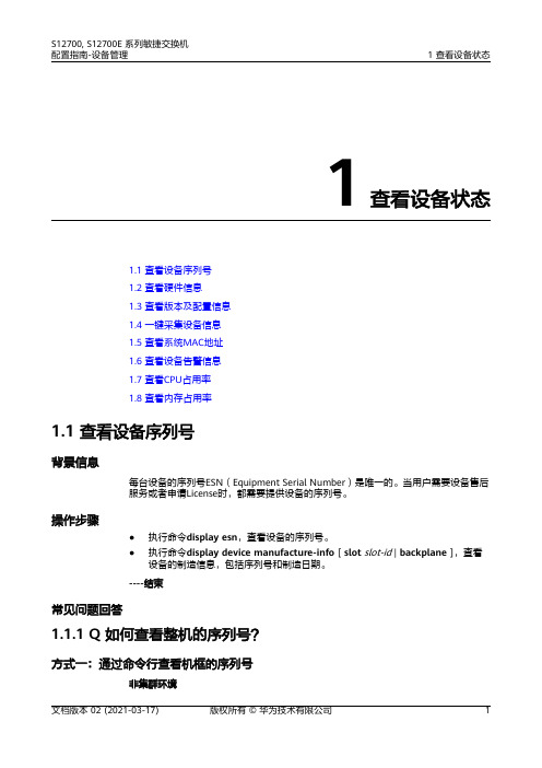
01-01 查看设备状态
1 查看设备状态 ᒿࡇਧḷㆮ
Clean periodically ᇐᵕᢡ
≤75 kg(165 lb)
RUN/ALM
CAUTION ћbkHeoaed食zpyai൞rnpdgao伄rfutisnsgamewᰁroasv䖢yia.nngᰬdpoatrh䀜tse,r ਬέ
Y7S8NE1:T021D1B0C2S011012047210482S0
[Main_Board] DATE=13_02_08 SN=2102310JFA6TGC907205
文档版本 02 (2021-03-17)
版权所有 © 华为技术有限公司
7
S12700, S12700E 系列敏捷交换机 配置指南-设备管理
1 查看设备状态
说明 不同版本命令格式可能略有差异,可通过输入“?”获取命令提示信息,选择对应的电源参数。
<cr>
<HUAWEI> display elabel 1/?
<5,8,13,16>
<CMU1>
<FAN1-FAN5>
<PWR1-PWR4>
<HUAWEI> display elabel 1/PWR1
Warning: It may take a long time to excute this command. Continue? [Y/N]:y
● 序列号标签在单板面板的右上角。
ᒿࡇਧḷㆮ
21023168676TB300 Y3 EH1D2T24XEA0
● 序列号标签在单板面板的左上角。 ᒿࡇਧḷㆮ
SN:21021209 9510DA000256 Y ET1MFBX00000
中兴交换机配置

一、系统的启动过程如下。
1、上电后,首先进行硬件启动,当硬件检测无误后,管理终端上出现下列信息:Welcome to use ZTE eCarrier!!Copyright(c) 2004-2006, ZTE Co。
, Ltd.System Booting..。
.。
CPU: S3C45010 ARM7TDMIBSP version: 1.2/0Creation date: Feb 11 2004, 09:37:01Press any key to stop auto-boot。
..72、出现上述信息后,等待大约7 秒,用户可以在这段时间内按任意键进入boot 状态,修改启动参数.当系统在规定时间未检测到用户输入时,系统便开始自动加载版本,并提示下列信息:auto—booting。
..boot device : secEndunit number : 0processor number : 0host name : tigerfile name : vxWorksinet on ethernet (e) : 10.40.92。
106host inet (h) : 10。
40.92.105flags (f) : 0x80Attaching to TFFS.。
done。
Loading version:/kernel.。
.1459932 + 75292 + 6358852Starting at 0x1656e0...Attaching interface lo0。
.。
done(省略)Welcome !ZTE Corporation。
All rights reserved.login:adminpassword:*********3、系统启动成功后,出现提示符login:,要求输入登录用户名和密码,缺省用户名是admin,密码是zhongxing。
二、配置开始工作1.打开超级终端,输入连接的名称,如ZXR10,并选择一个图标。
nmi detected please consult -回复
nmi detected please consult -回复什么是nmi?NMI(Non-Maskable Interrupt)是一种特殊类型的中断,用于通知处理器发生了一个严重的系统故障,需要立即停止当前的执行并执行一些特殊的处理。
与可屏蔽中断相比,NMI无法被屏蔽或屏蔽。
它被设计成正常的中断处理器无法阻止或忽略的紧急情况。
NMI的发生原因?NMI中断通常由硬件故障、内存错误、总线故障或其他不容忽视的系统问题引起。
例如,当计算机系统遇到故障的电源供应、内存读写错误、CPU 过热等问题时,硬件会触发NMI中断来通知处理器出现问题。
因为NMI 无法被屏蔽,所以即使处理器被卡住或处于繁忙状态,也会立即响应NMI 中断。
NMI的处理过程?当NMI中断发生时,处理器会立即停止当前的执行,并跳转到指定的中断处理例程。
这个处理例程通常由操作系统或硬件厂商提供,并用于处理紧急情况。
处理例程通常会执行以下操作:1. 保存处理器状态:首先,处理例程会保存处理器的当前状态,包括通用寄存器、程序计数器、标志寄存器等。
这样做是为了确保在处理完NMI 后,能够恢复到正常的执行状态。
2. 处理紧急情况:接下来,处理例程会根据NMI中断的具体原因来执行相应的处理操作。
例如,如果是硬件故障导致的NMI,处理例程可能会尝试重新初始化故障设备或进行一些其他修复措施。
3. 恢复正常执行:处理例程完成紧急处理后,会恢复处理器的正常执行状态。
它会从之前保存的状态中恢复寄存器的值,并将程序计数器设置回原来的位置,以确保处理器可以继续执行被中断的程序或任务。
为什么NMI无法被屏蔽?NMI被设计成无法被处理器屏蔽或忽略的原因在于它的紧急性和重要性。
由于NMI通常是由严重的系统故障引起的,忽略NMI可能会导致更严重的问题,甚至损坏硬件或丢失数据。
因此,处理器必须响应NMI中断,并执行相应的紧急处理操作,以确保系统能够尽快恢复正常工作状态。
NMI的应用和意义?NMI中断被广泛应用于计算机系统的可靠性和可用性方面。
Schneider Electric电子热漏保护器LR9F5369TeSys数据手册说明书
T h e i n f o r m a t i o n p r o v i d e d i n t h i s d o c u m e n t a t i o n c o n t a i n s g e n e r a l d e s c r i p t i o n s a n d /o r t e c h n i c a l c h a r a c t e r i s t i c s o f t h e p e r f o r m a n c e o f t h e p r o d u c t s c o n t a i n e d h e r e i n .T h i s d o c u m e n t a t i o n i s n o t i n t e n d e d a s a s u b s t i t u t e f o r a n d i s n o t t o b e u s e d f o r d e t e r m i n i n g s u i t a b i l i t y o r r e l i a b i l i t y o f t h e s e p r o d u c t s f o r s p e c i f i c u s e r a p p l i c a t i o n s .I t i s t h e d u t y o f a n y s u c h u s e r o r i n t e g r a t o r t o p e r f o r m t h e a p p r o p r i a t e a n d c o m p l e t e r i s k a n a l y s i s , e v a l u a t i o n a n d t e s t i n g o f t h e p r o d u c t s w i t h r e s p e c t t o t h e r e l e v a n t s p e c i f i c a p p l i c a t i o n o r u s e t h e r e o f .N e i t h e r S c h n e i d e r E l e c t r i c I n d u s t r i e s S A S n o r a n y o f i t s a f f i l i a t e s o r s u b s i d i a r i e s s h a l l b e r e s p o n s i b l e o r l i a b l e f o r m i s u s e o f t h e i n f o r m a t i o n c o n t a i n e d h e r e i n .Product data sheetCharacteristicsLR9F5369TeSys LRF - electronic thermal overload relay -90...150 A - class 10Product availability: Stock - Normally stocked in distribution facilityMainRange TeSys Product name TeSys LRF Device short name LR9FProduct or component typeElectronic thermal overload relay Relay application Motor protection Product compatibility LC1F115...LC1F185Network typeACThermal overload class Class 10 IEC 60947-4Thermal protection ad-justment range90…150 AComplementaryNetwork frequency 50/60 Hz Supply voltage limits 17…32 VMounting support Direct on contactor PlateTripping threshold 1.12 +/- 0.06 In tripping IEC 60947-4-1Surge withstand4 kV IEC 61000-4-5Contacts type and composition1 NO + 1 NC [Ith] conventional free air thermal current 5 A control circuit[Ue] rated operational voltage 1000 V AC 50/60 Hz power circuit VDE 0110 group C [Ui] rated insulation voltagePower circuit 1000 V AC IEC 60947-4[Uimp] rated impulse withstand voltage 8 kV IEC 60947-1Phase failure sensitivity Tripping in 4 s +/- 20 % IEC 60947-4-1Reset Manual reset on front relayControl typeDial white full-load current adjustment Test button redPush-button red reset Push-button stop Local signallingTrip indicatorTemperature compensation -4…158 °F (-20…70 °C)Current consumption <= 5 mA no-load Switching capacity for alarm 0...150 mA Maximum voltage drop <2.5 V closed stateConnections - terminalsControl circuit screw clamp terminals 1 0.00…0.00 in² (0.75…2.5 mm²) flexible -with cable endControl circuit screw clamp terminals 1 0.00…0.00 in² (0.75…2.5 mm²) solid Control circuit screw clamp terminals 1 0.00…0.01 in² (0.75…4 mm²) flexible -without cable endControl circuit screw clamp terminals 2 0.00…0.00 in² (1…1.5 mm²) flexible - with cable endControl circuit screw clamp terminals 2 0.00…0.00 in² (1…2.5 mm²) flexible -without cable endControl circuit screw clamp terminals 2 0.00 in² (1 mm²) solid Power circuit lugs-ring terminals M8Tightening torque Control circuit 1.2 N.m screw clamp terminals Power circuit 18 N.m screw clamp terminals Height 3.78 in (96 mm)Width4.53 in (115 mm)Depth 4.86 in (123.5 mm)Net weight 1.95 lb(US) (0.885 kg)EnvironmentStandards VDE 0660IEC 60255-17IEC 60947-4-1IEC 60255-8EN 60947-4-1Product certifications ULCSAProtective treatment THIP degree of protection IP20 IEC 60529IP20 VDE 0106Ambient air temperature for operation-4…131 °F (-20…55 °C) IEC 60255-8Ambient air temperature for storage-40…185 °F (-40…85 °C)Operating altitude<= 6561.68 ft (2000 m) without deratingFire resistance1562 °F (850 °C) IEC 60695-2-1Mechanical robustness Shocks13 Gn for 11 ms IEC 60068-2-7Vibrations 5...300 Hz2 Gn IEC 60068-2-6Dielectric strength6 kV 50 Hz IEC 255-5Electromagnetic compatibility Resistance to electrostatic discharge 6 kV in indirect mode IEC 61000-4-2Resistance to electrostatic discharge 8 kV in air IEC 61000-4-2Radiated radio-frequency electromagnetic field immunity test 10 V/m IEC61000-4-3Fast transients immunity test 2 kV IEC 61000-4-4Ordering and shipping detailsCategory22334 - CONTACTOR,F-LINE,OVERLOADSDiscount Schedule I12GTIN00785901566007Package weight(Lbs)0.87 kg (1.92 lb(US))Returnability YesCountry of origin FROffer SustainabilitySustainable offer status Green Premium productCalifornia proposition 65WARNING: This product can expose you to chemicals including: Antimony oxide& Antimony trioxide which is known to the State of California to cause Carcinogenharm. For more information go to REACh Regulation REACh DeclarationEU RoHS Directive Compliant EU RoHS DeclarationMercury free YesRoHS exemption information YesChina RoHS Regulation China RoHS DeclarationEnvironmental Disclosure Product Environmental ProfileCircularity Profile End Of Life InformationWEEE The product must be disposed on European Union markets following specificwaste collection and never end up in rubbish bins.Contractual warrantyWarranty18 months。
PolarFire SoC FPGA设备错误信息引用说明书

PolarFire® SoC FPGA Devices Errata IntroductionThe PolarFire® SoC FPGA family devices are subjected to the limitations described in this errata document. This document contains updated information about known devices specific issues and provides the available limitations and workarounds. Contact Microchip Technical Support for more information.PCB DesignsFor information about how to determine proper signal pinout, see PolarFire SoC FPGA Board Design Guidelines User Guide. The proper signal pinout is needed for all clocking, transceiver, and FPGA pin recommendations.Device IdentificationPolarFire SoC FPGA production samples can be identified as shown in the following figures.Figure 1. Device Identification Markings: Pre-Production DevicesFigure 2. Device Identification Markings: Production DevicesTable of ContentsIntroduction (1)PCB Designs (1)Device Identification (1)1. Errata Descriptions and Workarounds (4)1.1. Production Validation Status (5)2. Libero® SoC Software Errata (7)3. Embedded Software Errata (8)4. Revision History (9)Microchip Information (10)The Microchip Website (10)Product Change Notification Service (10)Customer Support (10)Microchip Devices Code Protection Feature (10)Legal Notice (10)Trademarks (11)Quality Management System (12)Worldwide Sales and Service (13)1. Errata Descriptions and WorkaroundsThe following section describes the device errata and the workarounds. The following table lists the errata for Engineering Samples (ES), Pre-Production (PP) silicon, and production silicon. For device part marking specifications, see 2. Device Identification.Table 1-1. Summary of PolarFire® SoC FPGA ErrataNotes: 1.Refers to Errata for PolarFire SoC ES devices.2.'*'—Indicates that that the errata exists for the specified silicon revision.3.'X'—Indicates that the issue is fixed in the specified silicon revision.1.1 Production Validation StatusThis section details the PolarFire SoC MPFS025T and PolarFire SoC MPFS250T product validation status forRevision 0.1.1.1 eMMC HS400 and HS400 Enhanced Strobe ModeseMMC validation over process, voltage, and temperature is completed for all the supported modes except for eMMC HS400 and HS400 Enhanced Strobe (HS400-ES) modes. The validation status is listed as follows:•HS400 mode: Compliance is in progress.•HS400-ES mode: Validation and compliance are in progress.See PolarFire SOC MSS Technical Reference Manual for more information about eMMC supported modes or contact Microchip Technical Support.1.1.2 LPDDR4 Bring Up, Debug, and ValidationLPDDR4 validation over process, voltage, and temperature is completed. See PolarFire® SoC FPGA Board DesignGuidelines User Guide for reference board design files and board design practices to achieve expected performance from PCBs and PolarFire SoC devices.Important: Additional collateral is created to provide guidelines for design, bring up, debug, andvalidation of LPDDR4-based system. This collateral will be available by July 2022. Contact MicrochipTechnical Support for more information.1.1.3 SD ComplianceThe following lists the SD compliance status.•SD validation over process, voltage, and temperature is completed for all the modes.•Compliance is completed for SD-DS and SD-HS modes.•Compliance for UHS-I SDR12, UHS-I SDR25, UHS-I SDR50, UHS-I SDR104, and UHS-I DDR50 is in progress.See PolarFire SOC MSS Technical Reference Manual for more information about SD supported modes or contactMicrochip Technical Support.2. Libero® SoC Software ErrataFor Libero SoC related issues and limitations, see Libero SoC Release Notes.3. Embedded Software ErrataSee SoftConsole Release Notes for more information.Revision History 4. Revision HistoryMicrochip InformationThe Microchip WebsiteMicrochip provides online support via our website at /. This website is used to make files and information easily available to customers. Some of the content available includes:•Product Support – Data sheets and errata, application notes and sample programs, design resources, user’s guides and hardware support documents, latest software releases and archived software•General Technical Support – Frequently Asked Questions (FAQs), technical support requests, online discussion groups, Microchip design partner program member listing•Business of Microchip – Product selector and ordering guides, latest Microchip press releases, listing of seminars and events, listings of Microchip sales offices, distributors and factory representativesProduct Change Notification ServiceMicrochip’s product change notification service helps keep customers current on Microchip products. Subscribers will receive email notification whenever there are changes, updates, revisions or errata related to a specified product family or development tool of interest.To register, go to /pcn and follow the registration instructions.Customer SupportUsers of Microchip products can receive assistance through several channels:•Distributor or Representative•Local Sales Office•Embedded Solutions Engineer (ESE)•Technical SupportCustomers should contact their distributor, representative or ESE for support. Local sales offices are also available to help customers. A listing of sales offices and locations is included in this document.Technical support is available through the website at: /supportMicrochip Devices Code Protection FeatureNote the following details of the code protection feature on Microchip products:•Microchip products meet the specifications contained in their particular Microchip Data Sheet.•Microchip believes that its family of products is secure when used in the intended manner, within operating specifications, and under normal conditions.•Microchip values and aggressively protects its intellectual property rights. Attempts to breach the code protection features of Microchip product is strictly prohibited and may violate the Digital Millennium Copyright Act.•Neither Microchip nor any other semiconductor manufacturer can guarantee the security of its code. Code protection does not mean that we are guaranteeing the product is “unbreakable”. Code protection is constantly evolving. Microchip is committed to continuously improving the code protection features of our products. Legal NoticeThis publication and the information herein may be used only with Microchip products, including to design, test,and integrate Microchip products with your application. Use of this information in any other manner violates these terms. Information regarding device applications is provided only for your convenience and may be supersededby updates. It is your responsibility to ensure that your application meets with your specifications. Contact yourlocal Microchip sales office for additional support or, obtain additional support at /en-us/support/ design-help/client-support-services.THIS INFORMATION IS PROVIDED BY MICROCHIP "AS IS". MICROCHIP MAKES NO REPRESENTATIONSOR WARRANTIES OF ANY KIND WHETHER EXPRESS OR IMPLIED, WRITTEN OR ORAL, STATUTORYOR OTHERWISE, RELATED TO THE INFORMATION INCLUDING BUT NOT LIMITED TO ANY IMPLIED WARRANTIES OF NON-INFRINGEMENT, MERCHANTABILITY, AND FITNESS FOR A PARTICULAR PURPOSE, OR WARRANTIES RELATED TO ITS CONDITION, QUALITY, OR PERFORMANCE.IN NO EVENT WILL MICROCHIP BE LIABLE FOR ANY INDIRECT, SPECIAL, PUNITIVE, INCIDENTAL, OR CONSEQUENTIAL LOSS, DAMAGE, COST, OR EXPENSE OF ANY KIND WHATSOEVER RELATED TO THE INFORMATION OR ITS USE, HOWEVER CAUSED, EVEN IF MICROCHIP HAS BEEN ADVISED OF THE POSSIBILITY OR THE DAMAGES ARE FORESEEABLE. TO THE FULLEST EXTENT ALLOWED BY LAW, MICROCHIP'S TOTAL LIABILITY ON ALL CLAIMS IN ANY WAY RELATED TO THE INFORMATION OR ITS USE WILL NOT EXCEED THE AMOUNT OF FEES, IF ANY, THAT YOU HAVE PAID DIRECTLY TO MICROCHIP FOR THE INFORMATION.Use of Microchip devices in life support and/or safety applications is entirely at the buyer's risk, and the buyer agrees to defend, indemnify and hold harmless Microchip from any and all damages, claims, suits, or expenses resulting from such use. No licenses are conveyed, implicitly or otherwise, under any Microchip intellectual property rights unless otherwise stated.TrademarksThe Microchip name and logo, the Microchip logo, Adaptec, AVR, AVR logo, AVR Freaks, BesTime, BitCloud, CryptoMemory, CryptoRF, dsPIC, flexPWR, HELDO, IGLOO, JukeBlox, KeeLoq, Kleer, LANCheck, LinkMD, maXStylus, maXTouch, MediaLB, megaAVR, Microsemi, Microsemi logo, MOST, MOST logo, MPLAB, OptoLyzer, PIC, picoPower, PICSTART, PIC32 logo, PolarFire, Prochip Designer, QTouch, SAM-BA, SenGenuity, SpyNIC, SST, SST Logo, SuperFlash, Symmetricom, SyncServer, Tachyon, TimeSource, tinyAVR, UNI/O, Vectron, and XMEGA are registered trademarks of Microchip Technology Incorporated in the U.S.A. and other countries.AgileSwitch, APT, ClockWorks, The Embedded Control Solutions Company, EtherSynch, Flashtec, Hyper Speed Control, HyperLight Load, Libero, motorBench, mTouch, Powermite 3, Precision Edge, ProASIC, ProASIC Plus, ProASIC Plus logo, Quiet- Wire, SmartFusion, SyncWorld, Temux, TimeCesium, TimeHub, TimePictra, TimeProvider, TrueTime, and ZL are registered trademarks of Microchip Technology Incorporated in the U.S.A.Adjacent Key Suppression, AKS, Analog-for-the-Digital Age, Any Capacitor, AnyIn, AnyOut, Augmented Switching, BlueSky, BodyCom, Clockstudio, CodeGuard, CryptoAuthentication, CryptoAutomotive, CryptoCompanion, CryptoController, dsPICDEM, , Dynamic Average Matching, DAM, ECAN, Espresso T1S, EtherGREEN, GridTime, IdealBridge, In-Circuit Serial Programming, ICSP, INICnet, Intelligent Paralleling, IntelliMOS, Inter-Chip Connectivity, JitterBlocker, Knob-on-Display, KoD, maxCrypto, maxView, memBrain, Mindi, MiWi, MPASM, MPF, MPLAB Certified logo, MPLIB, MPLINK, MultiTRAK, NetDetach, Omniscient Code Generation, PICDEM, , PICkit, PICtail, PowerSmart, PureSilicon, QMatrix, REAL ICE, Ripple Blocker, RTAX, RTG4, SAM-ICE, Serial Quad I/O, simpleMAP, SimpliPHY, SmartBuffer, SmartHLS, SMART-I.S., storClad, SQI, SuperSwitcher, SuperSwitcher II, Switchtec, SynchroPHY, Total Endurance, Trusted Time, TSHARC, USBCheck, VariSense, VectorBlox, VeriPHY, ViewSpan, WiperLock, XpressConnect, and ZENA are trademarks of Microchip Technology Incorporated in the U.S.A. and other countries.SQTP is a service mark of Microchip Technology Incorporated in the U.S.A.The Adaptec logo, Frequency on Demand, Silicon Storage Technology, and Symmcom are registered trademarks of Microchip Technology Inc. in other countries.GestIC is a registered trademark of Microchip Technology Germany II GmbH & Co. KG, a subsidiary of Microchip Technology Inc., in other countries.All other trademarks mentioned herein are property of their respective companies.© 2022, Microchip Technology Incorporated and its subsidiaries. All Rights Reserved.ISBN: 978-1-6683-0750-2Quality Management SystemFor information regarding Microchip’s Quality Management Systems, please visit /quality.Worldwide Sales and Service。
海思ot开头的函数 -回复
海思ot开头的函数-回复"海思OT开头的函数"是指海思芯片(HiSilicon)的操作系统层(OT, Operating System)的函数库,用于开发嵌入式系统和应用程序。
海思芯片是华为技术有限公司的全资子公司,致力于半导体技术创新和应用解决方案的开发。
海思OT函数库提供了许多功能强大且灵活的函数,用于协助开发人员编写高效、可靠和安全的嵌入式系统和应用程序。
一. 海思OT开头的函数库概述海思OT函数库是海思芯片提供的一组操作系统层的函数库,主要包括以下几个方面的功能:1. 定时器函数:海思OT函数库提供了精确计时和延时函数,帮助开发人员进行时间控制和任务调度。
2. 任务管理函数:海思OT函数库支持多任务管理,包括任务的创建、删除、挂起和恢复等操作。
3. 事件管理函数:海思OT函数库提供了事件管理的功能,支持事件的等待、发送和清除等操作,用于任务之间的同步和通信。
4. 内存管理函数:海思OT函数库提供了内存的动态分配和释放函数,帮助开发人员进行内存资源的管理和优化。
5. 信号量函数:海思OT函数库支持信号量操作,包括创建、等待和发送等操作,用于任务之间的同步和互斥。
二. 定时器函数的使用定时器函数是海思OT函数库的核心功能之一,使用定时器函数可以实现准确的时间控制和任务调度。
在使用定时器函数之前,需要进行如下步骤:1. 引入头文件:在源代码文件中引入海思OT函数库的头文件,以便使用其中的函数。
2. 初始化定时器:使用`OT_Timer_Init()`函数进行定时器的初始化配置,包括定时周期和中断优先级等参数。
3. 定时器中断处理函数:编写定时器中断处理函数,用于处理定时器中断事件。
4. 启动定时器:使用`OT_Timer_Start()`函数启动定时器,开始计时和触发定时器中断。
在定时器函数的使用过程中,可以根据实际需要进行定时器的启动、停止和重设等操作,以实现精确的时间控制和任务调度。
STM32固件库使用手册_v3.5版本

Indradrive 系列 故障代码
Error MessagesF9001 Error internal function call.F9002 Error internal RTOS function callF9003 WatchdogF9004 Hardware trapF8000 Fatal hardware errorF8010 Autom. commutation: Max. motion range when moving back F8011 Commutation offset could not be determinedF8012 Autom. commutation: Max. motion rangeF8013 Automatic commutation: Current too lowF8014 Automatic commutation: OvercurrentF8015 Automatic commutation: TimeoutF8016 Automatic commutation: Iteration without resultF8017 Automatic commutation: Incorrect commutation adjustment F8018 Device overtemperature shutdownF8022 Enc. 1: Enc. signals incorr. (can be cleared in ph. 2) F8023 Error mechanical link of encoder or motor connectionF8025 Overvoltage in power sectionF8027 Safe torque off while drive enabledF8028 Overcurrent in power sectionF8030 Safe stop 1 while drive enabledF8042 Encoder 2 error: Signal amplitude incorrectF8057 Device overload shutdownF8060 Overcurrent in power sectionF8064 Interruption of motor phaseF8067 Synchronization PWM-Timer wrongF8069 +/-15Volt DC errorF8070 +24Volt DC errorF8076 Error in error angle loopF8078 Speed loop error.F8079 Velocity limit value exceededF8091 Power section defectiveF8100 Error when initializing the parameter handlingF8102 Error when initializing power sectionF8118 Invalid power section/firmware combinationF8120 Invalid control section/firmware combinationF8122 Control section defectiveF8129 Incorrect optional module firmwareF8130 Firmware of option 2 of safety technology defectiveF8133 Error when checking interrupting circuitsF8134 SBS: Fatal errorF8135 SMD: Velocity exceededF8140 Fatal CCD error.F8201 Safety command for basic initialization incorrectF8203 Safety technology configuration parameter invalidF8813 Connection error mains chokeF8830 Power section errorF8838 Overcurrent external braking resistorF7010 Safely-limited increment exceededF7011 Safely-monitored position, exceeded in pos. DirectionF7012 Safely-monitored position, exceeded in neg. DirectionF7013 Safely-limited speed exceededF7020 Safe maximum speed exceededF7021 Safely-limited position exceededF7030 Position window Safe stop 2 exceededF7031 Incorrect direction of motionF7040 Validation error parameterized - effective thresholdF7041 Actual position value validation errorF7042 Validation error of safe operation modeF7043 Error of output stage interlockF7050 Time for stopping process exceeded8.3.15 F7051 Safely-monitored deceleration exceeded (159)8.4 Travel Range Errors (F6xxx) (161)8.4.1 Behavior in the Case of Travel Range Errors (161)8.4.2 F6010 PLC Runtime Error (162)8.4.3 F6024 Maximum braking time exceeded (163)8.4.4 F6028 Position limit value exceeded (overflow) (164)8.4.5 F6029 Positive position limit exceeded (164)8.4.6 F6030 Negative position limit exceeded (165)8.4.7 F6034 Emergency-Stop (166)8.4.8 F6042 Both travel range limit switches activated (167)8.4.9 F6043 Positive travel range limit switch activated (167)8.4.10 F6044 Negative travel range limit switch activated (168)8.4.11 F6140 CCD slave error (emergency halt) (169)8.5 Interface Errors (F4xxx) (169)8.5.1 Behavior in the Case of Interface Errors (169)8.5.2 F4001 Sync telegram failure (170)8.5.3 F4002 RTD telegram failure (171)8.5.4 F4003 Invalid communication phase shutdown (172)8.5.5 F4004 Error during phase progression (172)8.5.6 F4005 Error during phase regression (173)8.5.7 F4006 Phase switching without ready signal (173)8.5.8 F4009 Bus failure (173)8.5.9 F4012 Incorrect I/O length (175)8.5.10 F4016 PLC double real-time channel failure (176)8.5.11 F4017 S-III: Incorrect sequence during phase switch (176)8.5.12 F4034 Emergency-Stop (177)8.5.13 F4140 CCD communication error (178)8.6 Non-Fatal Safety Technology Errors (F3xxx) (178)8.6.1 Behavior in the Case of Non-Fatal Safety Technology Errors (178)8.6.2 F3111 Refer. missing when selecting safety related end pos (179)8.6.3 F3112 Safe reference missing (179)8.6.4 F3115 Brake check time interval exceeded (181)Troubleshooting Guide | Rexroth IndraDrive Electric Drivesand ControlsI Bosch Rexroth AG VII/XXIITable of ContentsPage8.6.5 F3116 Nominal load torque of holding system exceeded (182)8.6.6 F3117 Actual position values validation error (182)8.6.7 F3122 SBS: System error (183)8.6.8 F3123 SBS: Brake check missing (184)8.6.9 F3130 Error when checking input signals (185)8.6.10 F3131 Error when checking acknowledgment signal (185)8.6.11 F3132 Error when checking diagnostic output signal (186)8.6.12 F3133 Error when checking interrupting circuits (187)8.6.13 F3134 Dynamization time interval incorrect (188)8.6.14 F3135 Dynamization pulse width incorrect (189)8.6.15 F3140 Safety parameters validation error (192)8.6.16 F3141 Selection validation error (192)8.6.17 F3142 Activation time of enabling control exceeded (193)8.6.18 F3143 Safety command for clearing errors incorrect (194)8.6.19 F3144 Incorrect safety configuration (195)8.6.20 F3145 Error when unlocking the safety door (196)8.6.21 F3146 System error channel 2 (197)8.6.22 F3147 System error channel 1 (198)8.6.23 F3150 Safety command for system start incorrect (199)8.6.24 F3151 Safety command for system halt incorrect (200)8.6.25 F3152 Incorrect backup of safety technology data (201)8.6.26 F3160 Communication error of safe communication (202)8.7 Non-Fatal Errors (F2xxx) (202)8.7.1 Behavior in the Case of Non-Fatal Errors (202)8.7.2 F2002 Encoder assignment not allowed for synchronization (203)8.7.3 F2003 Motion step skipped (203)8.7.4 F2004 Error in MotionProfile (204)8.7.5 F2005 Cam table invalid (205)8.7.6 F2006 MMC was removed (206)8.7.7 F2007 Switching to non-initialized operation mode (206)8.7.8 F2008 RL The motor type has changed (207)8.7.9 F2009 PL Load parameter default values (208)8.7.10 F2010 Error when initializing digital I/O (-> S-0-0423) (209)8.7.11 F2011 PLC - Error no. 1 (210)8.7.12 F2012 PLC - Error no. 2 (210)8.7.13 F2013 PLC - Error no. 3 (211)8.7.14 F2014 PLC - Error no. 4 (211)8.7.15 F2018 Device overtemperature shutdown (211)8.7.16 F2019 Motor overtemperature shutdown (212)8.7.17 F2021 Motor temperature monitor defective (213)8.7.18 F2022 Device temperature monitor defective (214)8.7.19 F2025 Drive not ready for control (214)8.7.20 F2026 Undervoltage in power section (215)8.7.21 F2027 Excessive oscillation in DC bus (216)8.7.22 F2028 Excessive deviation (216)8.7.23 F2031 Encoder 1 error: Signal amplitude incorrect (217)VIII/XXII Bosch Rexroth AG | Electric Drivesand ControlsRexroth IndraDrive | Troubleshooting GuideTable of ContentsPage8.7.24 F2032 Validation error during commutation fine adjustment (217)8.7.25 F2033 External power supply X10 error (218)8.7.26 F2036 Excessive position feedback difference (219)8.7.27 F2037 Excessive position command difference (220)8.7.28 F2039 Maximum acceleration exceeded (220)8.7.29 F2040 Device overtemperature 2 shutdown (221)8.7.30 F2042 Encoder 2: Encoder signals incorrect (222)8.7.31 F2043 Measuring encoder: Encoder signals incorrect (222)8.7.32 F2044 External power supply X15 error (223)8.7.33 F2048 Low battery voltage (224)8.7.34 F2050 Overflow of target position preset memory (225)8.7.35 F2051 No sequential block in target position preset memory (225)8.7.36 F2053 Incr. encoder emulator: Pulse frequency too high (226)8.7.37 F2054 Incr. encoder emulator: Hardware error (226)8.7.38 F2055 External power supply dig. I/O error (227)8.7.39 F2057 Target position out of travel range (227)8.7.40 F2058 Internal overflow by positioning input (228)8.7.41 F2059 Incorrect command value direction when positioning (229)8.7.42 F2063 Internal overflow master axis generator (230)8.7.43 F2064 Incorrect cmd value direction master axis generator (230)8.7.44 F2067 Synchronization to master communication incorrect (231)8.7.45 F2068 Brake error (231)8.7.46 F2069 Error when releasing the motor holding brake (232)8.7.47 F2074 Actual pos. value 1 outside absolute encoder window (232)8.7.48 F2075 Actual pos. value 2 outside absolute encoder window (233)8.7.49 F2076 Actual pos. value 3 outside absolute encoder window (234)8.7.50 F2077 Current measurement trim wrong (235)8.7.51 F2086 Error supply module (236)8.7.52 F2087 Module group communication error (236)8.7.53 F2100 Incorrect access to command value memory (237)8.7.54 F2101 It was impossible to address MMC (237)8.7.55 F2102 It was impossible to address I2C memory (238)8.7.56 F2103 It was impossible to address EnDat memory (238)8.7.57 F2104 Commutation offset invalid (239)8.7.58 F2105 It was impossible to address Hiperface memory (239)8.7.59 F2110 Error in non-cyclical data communic. of power section (240)8.7.60 F2120 MMC: Defective or missing, replace (240)8.7.61 F2121 MMC: Incorrect data or file, create correctly (241)8.7.62 F2122 MMC: Incorrect IBF file, correct it (241)8.7.63 F2123 Retain data backup impossible (242)8.7.64 F2124 MMC: Saving too slowly, replace (243)8.7.65 F2130 Error comfort control panel (243)8.7.66 F2140 CCD slave error (243)8.7.67 F2150 MLD motion function block error (244)8.7.68 F2174 Loss of motor encoder reference (244)8.7.69 F2175 Loss of optional encoder reference (245)Troubleshooting Guide | Rexroth IndraDrive Electric Drivesand Controls| Bosch Rexroth AG IX/XXIITable of ContentsPage8.7.70 F2176 Loss of measuring encoder reference (246)8.7.71 F2177 Modulo limitation error of motor encoder (246)8.7.72 F2178 Modulo limitation error of optional encoder (247)8.7.73 F2179 Modulo limitation error of measuring encoder (247)8.7.74 F2190 Incorrect Ethernet configuration (248)8.7.75 F2260 Command current limit shutoff (249)8.7.76 F2270 Analog input 1 or 2, wire break (249)8.7.77 F2802 PLL is not synchronized (250)8.7.78 F2814 Undervoltage in mains (250)8.7.79 F2815 Overvoltage in mains (251)8.7.80 F2816 Softstart fault power supply unit (251)8.7.81 F2817 Overvoltage in power section (251)8.7.82 F2818 Phase failure (252)8.7.83 F2819 Mains failure (253)8.7.84 F2820 Braking resistor overload (253)8.7.85 F2821 Error in control of braking resistor (254)8.7.86 F2825 Switch-on threshold braking resistor too low (255)8.7.87 F2833 Ground fault in motor line (255)8.7.88 F2834 Contactor control error (256)8.7.89 F2835 Mains contactor wiring error (256)8.7.90 F2836 DC bus balancing monitor error (257)8.7.91 F2837 Contactor monitoring error (257)8.7.92 F2840 Error supply shutdown (257)8.7.93 F2860 Overcurrent in mains-side power section (258)8.7.94 F2890 Invalid device code (259)8.7.95 F2891 Incorrect interrupt timing (259)8.7.96 F2892 Hardware variant not supported (259)8.8 SERCOS Error Codes / Error Messages of Serial Communication (259)9 Warnings (Exxxx) (263)9.1 Fatal Warnings (E8xxx) (263)9.1.1 Behavior in the Case of Fatal Warnings (263)9.1.2 E8025 Overvoltage in power section (263)9.1.3 E8026 Undervoltage in power section (264)9.1.4 E8027 Safe torque off while drive enabled (265)9.1.5 E8028 Overcurrent in power section (265)9.1.6 E8029 Positive position limit exceeded (266)9.1.7 E8030 Negative position limit exceeded (267)9.1.8 E8034 Emergency-Stop (268)9.1.9 E8040 Torque/force actual value limit active (268)9.1.10 E8041 Current limit active (269)9.1.11 E8042 Both travel range limit switches activated (269)9.1.12 E8043 Positive travel range limit switch activated (270)9.1.13 E8044 Negative travel range limit switch activated (271)9.1.14 E8055 Motor overload, current limit active (271)9.1.15 E8057 Device overload, current limit active (272)X/XXII Bosch Rexroth AG | Electric Drivesand ControlsRexroth IndraDrive | Troubleshooting GuideTable of ContentsPage9.1.16 E8058 Drive system not ready for operation (273)9.1.17 E8260 Torque/force command value limit active (273)9.1.18 E8802 PLL is not synchronized (274)9.1.19 E8814 Undervoltage in mains (275)9.1.20 E8815 Overvoltage in mains (275)9.1.21 E8818 Phase failure (276)9.1.22 E8819 Mains failure (276)9.2 Warnings of Category E4xxx (277)9.2.1 E4001 Double MST failure shutdown (277)9.2.2 E4002 Double MDT failure shutdown (278)9.2.3 E4005 No command value input via master communication (279)9.2.4 E4007 SERCOS III: Consumer connection failed (280)9.2.5 E4008 Invalid addressing command value data container A (280)9.2.6 E4009 Invalid addressing actual value data container A (281)9.2.7 E4010 Slave not scanned or address 0 (281)9.2.8 E4012 Maximum number of CCD slaves exceeded (282)9.2.9 E4013 Incorrect CCD addressing (282)9.2.10 E4014 Incorrect phase switch of CCD slaves (283)9.3 Possible Warnings When Operating Safety Technology (E3xxx) (283)9.3.1 Behavior in Case a Safety Technology Warning Occurs (283)9.3.2 E3100 Error when checking input signals (284)9.3.3 E3101 Error when checking acknowledgment signal (284)9.3.4 E3102 Actual position values validation error (285)9.3.5 E3103 Dynamization failed (285)9.3.6 E3104 Safety parameters validation error (286)9.3.7 E3105 Validation error of safe operation mode (286)9.3.8 E3106 System error safety technology (287)9.3.9 E3107 Safe reference missing (287)9.3.10 E3108 Safely-monitored deceleration exceeded (288)9.3.11 E3110 Time interval of forced dynamization exceeded (289)9.3.12 E3115 Prewarning, end of brake check time interval (289)9.3.13 E3116 Nominal load torque of holding system reached (290)9.4 Non-Fatal Warnings (E2xxx) (290)9.4.1 Behavior in Case a Non-Fatal Warning Occurs (290)9.4.2 E2010 Position control with encoder 2 not possible (291)9.4.3 E2011 PLC - Warning no. 1 (291)9.4.4 E2012 PLC - Warning no. 2 (291)9.4.5 E2013 PLC - Warning no. 3 (292)9.4.6 E2014 PLC - Warning no. 4 (292)9.4.7 E2021 Motor temperature outside of measuring range (292)9.4.8 E2026 Undervoltage in power section (293)9.4.9 E2040 Device overtemperature 2 prewarning (294)9.4.10 E2047 Interpolation velocity = 0 (294)9.4.11 E2048 Interpolation acceleration = 0 (295)9.4.12 E2049 Positioning velocity >= limit value (296)9.4.13 E2050 Device overtemp. Prewarning (297)Troubleshooting Guide | Rexroth IndraDrive Electric Drivesand Controls| Bosch Rexroth AG XI/XXIITable of ContentsPage9.4.14 E2051 Motor overtemp. prewarning (298)9.4.15 E2053 Target position out of travel range (298)9.4.16 E2054 Not homed (300)9.4.17 E2055 Feedrate override S-0-0108 = 0 (300)9.4.18 E2056 Torque limit = 0 (301)9.4.19 E2058 Selected positioning block has not been programmed (302)9.4.20 E2059 Velocity command value limit active (302)9.4.21 E2061 Device overload prewarning (303)9.4.22 E2063 Velocity command value > limit value (304)9.4.23 E2064 Target position out of num. range (304)9.4.24 E2069 Holding brake torque too low (305)9.4.25 E2070 Acceleration limit active (306)9.4.26 E2074 Encoder 1: Encoder signals disturbed (306)9.4.27 E2075 Encoder 2: Encoder signals disturbed (307)9.4.28 E2076 Measuring encoder: Encoder signals disturbed (308)9.4.29 E2077 Absolute encoder monitoring, motor encoder (encoder alarm) (308)9.4.30 E2078 Absolute encoder monitoring, opt. encoder (encoder alarm) (309)9.4.31 E2079 Absolute enc. monitoring, measuring encoder (encoder alarm) (309)9.4.32 E2086 Prewarning supply module overload (310)9.4.33 E2092 Internal synchronization defective (310)9.4.34 E2100 Positioning velocity of master axis generator too high (311)9.4.35 E2101 Acceleration of master axis generator is zero (312)9.4.36 E2140 CCD error at node (312)9.4.37 E2270 Analog input 1 or 2, wire break (312)9.4.38 E2802 HW control of braking resistor (313)9.4.39 E2810 Drive system not ready for operation (314)9.4.40 E2814 Undervoltage in mains (314)9.4.41 E2816 Undervoltage in power section (314)9.4.42 E2818 Phase failure (315)9.4.43 E2819 Mains failure (315)9.4.44 E2820 Braking resistor overload prewarning (316)9.4.45 E2829 Not ready for power on (316)。
Modicon M580CPU 的操作状态
Modicon M580CPU 的操作状态
1、状态定义
下面列出了 CPU 的不同操作状态:
AUTOTEST: CPU 正在进行内部自检。
注意:如果扩展机架连接到本地机架,且线路端接器未插入机架扩展模块上未使用的连接器中,则在完成自检后, CPU 保持在AUTOTEST 状态。
NOCONF: 应用程序无效。
STOP: CPU 具有有效的应用程序,但已停止。
它本身设置为预定义的 STOP 状态参数,且在准备就绪时可以重新启动。
IDLE: CPU 具有有效的应用程序且能够解析逻辑,但应用程序不需要 CPU 处理(CPU 从未处于“ 运行” 状态)。
此状态不可见。
HALT: CPU 具有应用程序,但因遇到意外阻塞条件而停止运行。
使 CPU 处于 HALT 状态的条件可能导致可恢复或不可恢复的错误。
RUN: CPU 正在执行应用程序。
WAIT: 如果检测到断电状况,则 CPU 在备份其数据时处于暂时状态。
只有在电源恢复且电源储备得到补充时, CPU 才会再次启动。
CPU 处于暂时状态时,可能无法查看。
CPU 执行热重启以退出 WAIT 状态。
ERROR: 由于检测到硬件或系统错误, CPU 已停止。
在系统准备重新启动时, CPU 将执行冷启动以退出 ERROR 状态。
OS DOWNLOAD: CPU 固件下载正在进行中。
2、监控 CPU 的状态
CPU 前面板上的 LED 提供 CPU 状态的指示。
nmi detected please consult -回复
nmi detected please consult -回复「NMI detected, please consult」是计算机系统中的一种错误提示,它意味着计算机的处理器在执行指令时检测到了一个非法的操作或异常情况。
NMI(非屏蔽中断)是一种特殊类型的中断信号,具有最高的优先级,可用于处理系统中的严重错误或故障。
当计算机系统发生NMI错误时,处理器会立即停止当前的执行任务,并生成一个NMI信号,然后通知操作系统和其他相关硬件设备。
这个错误通常表示系统遇到了严重的问题,需要进行故障排除和修复,以维护系统的稳定运行。
要解决「NMI detected, please consult」错误,首先需要确定错误的来源。
有许多可能导致NMI错误的因素,包括硬件故障、驱动程序冲突、软件错误或操作系统问题等。
以下是一些可能的步骤:1. 检查硬件连接:首先,检查计算机的硬件连接是否正确。
确保所有插槽、插头和电缆都牢固连接,并检查硬件设备是否正常工作。
2. 查看系统日志:打开操作系统的事件查看器或系统日志,查找与NMI 错误相关的任何错误消息或警告。
这些信息可以提供关于错误发生的时间、位置和可能的原因的线索。
3. 更新驱动程序和固件:许多NMI错误是由于驱动程序或固件问题引起的。
确保已安装最新版本的驱动程序和固件,并及时更新它们以解决已知的问题。
4. 运行系统诊断工具:大多数计算机系统都提供了内置的诊断工具,可以扫描硬件故障并检测问题。
运行这些工具可以帮助确定是否存在硬件故障。
5. 检查内存和硬盘:使用内置的内存和硬盘测试工具对系统进行全面的扫描。
损坏的内存或硬盘驱动器可能会导致NMI错误。
6. 清理和冷却系统:过热可能会导致计算机系统发生故障。
确保计算机的散热器清洁,风扇正常工作,并且系统处于适当的通风环境中。
7. 检查电源供应:摆在控制你计算机正常运行的最常见问题之一是电源供应问题。
确保电源供应稳定,并检查电缆和连接是否完好无损。
C8892中文资料
trφ1, trφ2 tfφ1, tfφ2
tpwφ1
-
-
100
ns
-
3/fφmc
-
s
Clock pulse (φ2) width
tpwφ2
-
3/fφmc
-
s
End of scan
Voltage
Veos (H)
4.75
5.0
-
Veos (L)
-
-
0.4
V
pulse
Rise/fall time
treos, tfeos
Vscd +15 V
Vscg
20 p
-
+
×2
OP AMP 1 OP AMP 2
CLAMP ×3
OP AMP 3
+15 V GND -15 V MASTER START MASTER CLOCK TRIG. B-EOS
DATA VIDEO
I Timing chart
MASTER CLOCK mc MASTER START ms
•Video data rate is 1/6 of master clock frequency (62.5 kHz Max.). •The operation of circuit stroke length below 4.5 mm is recommended. •The relation between data video output voltage and output charges from NMOS image sensor can be expressed by the following formula.
-
辰芯 at指令 -回复
辰芯at指令-回复辰芯(Espressif Systems)是一家致力于物联网技术的研发和创新的公司,他们提供了无线通信芯片和模组,其中被广泛应用于物联网设备的一款产品就是辰芯ESP8266系列。
这个系列芯片具备了强大的运算能力、较低的功耗和丰富的接口,为物联网设备开发人员提供了许多便利。
其中,辰芯芯片的at指令集更是成为了物联网设备开发过程中不可或缺的一部分。
那么,什么是AT指令呢?AT指令(Attention Command)是一种通信设备用来与终端设备进行交互的规范。
通过使用AT指令,开发人员可以通过串口或者其他通信接口与辰芯芯片进行通信,从而实现对设备的控制和管理。
辰芯芯片支持一系列标准AT指令,如指令集包括但不限于:AT+RST(重启芯片)、AT+CWMODE(设置设备工作模式)、AT+CWJAP (连接无线网络)、AT+CIPSTART(建立TCP/UDP连接)等等。
在物联网设备的开发过程中,AT指令起到了至关重要的作用。
首先,AT 指令使得物联网设备可以与上位机实现简单、高效的通信。
开发人员可以通过AT指令向辰芯芯片发送命令,获取设备的状态和数据,也可以通过AT指令向设备发送指令,实现对设备的控制。
这极大地方便了开发人员的调试和测试工作,加快了开发进程。
其次,AT指令为物联网设备的扩展性提供了可能。
在开发过程中,我们经常会遇到需要与其他外部设备进行数据交换的情况。
通过AT指令,辰芯芯片可以作为一个接口,将外部设备的数据通过串口或者其他通信接口发送给上位机,或者将上位机的指令传递给外部设备。
这样,设备的功能可以进一步扩展,与其他系统进行集成和互通。
此外,AT指令也为物联网设备的固件升级提供了一个简单的途径。
开发人员可以通过AT指令实现固件更新的功能,无需使用繁琐复杂的烧录工具和流程。
这大大方便了设备的维护和升级,同时也提高了开发效率。
然而,AT指令存在一些限制和不足之处。
首先,AT指令的灵活性有限,只能实现简单的数据交换和设备控制。
CBM培训资料

Engineer ITControl Builder MVersion 3.2Getting Started工业工程IT控制应用开发版本 3.2入门山东恒拓科技开展本资料是由山东恒拓科技开展〔ABB系统集成商〕内部员工参考CBM原版说明书翻译整理而成,本书主要用于内部参考学习及客户培训使用,未经山东恒拓科技开展许可的前提下,其他任何人员不可擅自复制,传播。
译者:孔祥玉。
本文献中的所有信息可能会在没有通知的前提下发生修改,并且ABB拥有对所有信息的解释权。
对于本文献中可能出现的任何错误,ABB不负任何法律责任。
在本文献的使用过程中,ABB对于因自然或非自然因素而产生的直接的、间接的、特殊的和附带的所有损失不负任何责任,且ABB对本文献中软件和硬件的描述中产生的任何损失不负任何责任。
在没有ABB的许可之下,本文献或其中的章节不可进行复制,且其中内容不可授予第三方或任何未授权的应用。
版权拥有© 1999 ABB保存所有版权发行:2002年12月文献编号:3BSE 028 807 R201 Rev B商标本文中使用到的注册和商标:Windows 微软公司注册ActiveX 微软公司注册PostScript Adobe Systems Inc. 注册Acrobat Reader Adobe Systems Inc. 注册Industrial IT ABB 注册第一部Control Builder M目录关于本书简介 (6)第一章–介绍Control Builder M产品总览........................................................................ ... ... . (7)编程语言....................................................... ... ... ... ... ... . (7)工程开发器.................................................... ... . (7)库................................ ... ... (8)安装要求....................................................................... ....................... . (8)可以支持的控制器组态.......... .. ....................................... ....................... . (9)Control Builder和控制器组态................................................. (10)分散控制................ ....... ....... ....... ....... ....... ........................... ..................... .. (11)Control Builder现有版本及其差异........................................ (12)第二章–安装Control Builder M................ ..... ..... ..... ..... .. .. ... .. (13)逐步安装指南........................................................ .. .. ... (14)TCP/IP 网络协议................................................. ..... ..... ..... .. (14)设置...................................................................................... ...... ...... ...... .. (15)启动................... ..... ..... ..... ..... . (15)AC800M/C的MMS效劳器............................................................. . (15)添加删除程序...................... ..... ..... ..... .. (15)第三章–培训导言.............................. ..... ..... ..... .. (17)开始新工程.......................................... ......... ......... (17)工程开发器...................................................................... . (18)标题菜单工具 (36)库...................................................................................................................... .. (37)控制器.................................................................................................................... . 38 任务. (40)应用 (40)变量间接 (43)变量声明〔定义〕 (43)局部变量 (44)模拟 (47)关闭Control Builder M (49)第四章–举例– Shop Doors简介 (51)选择模板 (52)声明变量和数据类型 (53)变量声明 (54)使用ST语言编写代码 (56)改变编程语言 (56)声明功能块 (57)划分程序功能段 (58)代码输入 (59)模拟 (62)硬件组态 (64)连接I/O通道和应用 (65)第五章–下装和测试简介 (71)通过串行电缆进行操作系统下装 (71)给冗余控制器下装操作系统 (73)设定IP地址 (74)通过以太网下装工程 (77)在线测试 (91)附录AC800 M/C的OPC效劳器简介 (91)自动启动OPC效劳器OPC的组态面板第二部AC800M Controller Hardware目录关于本书第一章–简介产品总览 (27)AC 800M 控制器的突出特性 (38)第二章–安装安装环境要求 (41)电缆 (43)电源 (44)防护等级 (46)将AC 800M单元安装于标准DIN-Rail导轨 (47)安装PM856/860/861/TP830 控制器单元〔单独〕 (54)安装PM861/TP830 控制器单元〔冗余〕 (62)安装PROFIBUS DP 通讯单元,CI851/TP851 (65)安装RS232-C通讯单元, CI853/TP853 (69)安装PROFIBUS DP-V1通讯单元, CI854/TP854 (70)安装CEX-bus电缆 (74)安装ModuleBus 电缆 (75)安装SD82x 供电电源 (76)安装主断路器 (77)安装SS822冗余电源选择模块 (79)安装SB821外部电池 (83)安装I/O 单元 (83)柜体安装 (84)第三章–组态简介 (89)连接到Control Builder M (89)连接到控制网 (90)通讯方式 (91)控制器IP地址 (93)在Control Builder M设置冗余控制器 (93)I/O系统 (94)驱动系统 (98)供电系统 (100)柜体中的电源模块 (101)柜外电源设备Powering Field Equipment outside the Cabinet (101)外部+24 V DC 电源 (103)第四章–操作AC 800M 控制器(PM856/860/861) (107)启动 (110)启动模式 (110)自动切换到冗余后备控制器 (112)AC 800M系统运行检查 (113)观察单控制器的运行 (113)观察冗余控制器的运行 (115)第五章–维修维修频率 (117)更换电池 (118)内部电池 (118)SB821外部电池单元 (120)在线插拔 (124)更换PM861冗余控制器 (124)维修步骤 (125)查找问题 (126)PM856/860/861控制器单元 (126)PM861 CPU冗余单元 (127)内部电池/ SB821外部电池 (127)PROFIBUS DP – CI851 (128)RS232-C Channels – CI853 (132)PROFIBUS DP-V1 – CI854 (133)Table of Contents附录–硬件单元PM856/PM860和TP830 –控制器单元 (137)技术数据 (138)性能数据 (142)PM861 and TP830 –控制器单元 (143)技术数据 (144)性能数据 (146)CI851 和TP851 – PROFIBUS DP单元 (147)CI853 和TP853 – RS232-C单元 (155)CI854 和TP854 – PROFIBUS DP-V1 Interface (159)电源单元–SD821, SD822 和SD823 (175)SS822 – (冗余电源选择单元) (183)SB821外部电池 (187)其他 (189)TB850 -- CEX-bus终端电阻 (189)TB851 -- CEX-bus终端电阻 (190)TB807 ModuleBus终端电阻 (191)TB852 RCU 连接终端电阻 (191)TK850 CEX-bus 外部电缆 (191)TK851 RCU连接电缆 (191)TK853电缆 (192)TK212工具电缆 (193)第一部Control Builder M关于本书简介欢迎使用本软件〔Control IT for AC 800M/C〕----一个真正全开放的工业控制开发系统。
PowerDsine芯片集成解决方案开发包(CSDK)应用说明书

Software Download for PoE UnitsFigure 2 - System Set-upSoftwareCopy both files (SWUpdate.exe and pol30k.s19) toone directory. If the name of the (*.s19) file isdifferent than mentioned (e.g. ‘7023_007.s19’),rename it to ‘pol30k.s19’. Prior to downloadingprocess, the directory must contain only these twofiles.Download Process ____________It is strongly recommended that you exit all otherapplications, before running the download program.Perform the following steps:1. Connect one side of the cable to the PC COMport and the other side to the switch/hub serialcommunication interface.2. Run the SWUpdate.exe file.3. On the screen displayed, select the appropriateCOM port, and click the ‘Start Prog’ button(Figure 3).Figure 3: Selecting the COM Port4. Wait for the “successful programming” messageto appear (Figure 4).Figure 4: Programming Completed5. Click on the ‘OK’ button. The programming iscompleted successfully. You may now reset yoursystem and it expect a successful operation withthe new software version.Troubleshooting ______________During the download process you may encounterproblems resulting in error messages. Possible errormessages are shown hereafter:File not Found ErrorApplication Note 126 When this error message appears, do the following:(*.S19) file has the wrong name - rename itto ‘pol30k.s19’.(*.S19) file is located in a different directorythan ‘SWUpdate.exe’ - move the file to thecorrect directory.Communication ErrorWhen this error message appears, do the following:Malfunctioning PoE unit - try to reset the unit,by turning the main voltage off and on.Incorrect COM port setting - set theparameters as described in paragraph 3.Reset the PoE unit and retry.Mismatched COM port – verify you areworking with the same COM port the cable isconnected to. Reset the PoE unit and retry.Disconnected or malfunctioning cable - try toreconnect the cable. In case the problemrecurs, replace the cable. Reset the PoE unitand retry.Timeout errorThe above error indicates an error occurred duringdownload process.Corrective action is the same as for communicationerror.Notice ________________________________________________________ PowerDsine assumes no responsibility or liability arising from the use of this Application Note, as described herein, nor does it convey any license under its patent rights or the rights of others.The information contained herein is believed to be accurate and reliable at the time of printing. However, due to ongoing product improvements and revisions, PowerDsine cannot accept responsibility for inadvertent errors, inaccuracies, subsequent changes or omissions of printed material.PowerDsine Ltd. reserves the right to make changes to products and to their specifications as described in this document, at any time, without prior notice. No rights toany PowerDsine Ltd. Intellectual property are licensed to any third party, directly, by implication or by any other method.© 2003 PowerDsine Ltd.All rights reserved.PowerDsine is a registered trademark of PowerDsine LTD.All other products or trademarks are property of their respective owners.The product described by this manual is a licensed product of PowerDsine.Visit our web site at: call:+972-9-7755123 AN-126 technicalsupport,ForIn the USA: +631-756-4680 or 1-877-4-802-3A 10/03 (Rev. 2.0)。
LTE后台排障告警说明
目录一.No Contact 无连接告警 (4)二.NTP System Time Sync Fault (NTP系统时钟同步错误) (6)三.NumberOfHwEntitiesMismatch (实际硬件数量不匹配) (6)四. PasswordFileFault (密码文件故障) (8)五.Plug-InUnitGeneralProblem 插入单元故障 (8)六.Plug-In Unit HW Failure (插入单元硬件故障) (8)七.PowerFailure (供电故障) (9)八.SystemClockQualityDegradation 系统时钟质量降级 (9)九.TemperatureExceptionalTakenOutOfService特殊温度导致服务停止 (12)十.TemperatureAbnormalPerformanceDegraded温度异常导致性能降级 (13)十一.TemperatureSensorFailure 温度传感器故障 (14)十二.TimingSyncFault定时同步故障 (15)十三.TUHardwareFault时钟单元硬件故障 (16)十四.Upgrade Package Corrupt升级包损坏 (16)十五.VswrOverThreshold 天馈驻波超限 (17)十六.LicenseKeyFileFault :License文件错误或缺失 (18)十七.LicenseKeyMissing:许可证密钥丢失 (19)十八.LinkFailure:链路故障 (19)十九.LinkStability:链路稳定性故障 (20)二十.LossofSynchReferenceRedundancy:同步引用冗余丢失 (20)二十一.LossofTracking:失去同步 (21)二十二.NetworkSynchTimefromGPSMissing:从GPS获取的网络时钟同步丢失 (21)二十三.功能资源丢失 (21)二十四.常规硬件错误 (22)二十五.常规软件错误 (22)二十六.Giga以太网链路故障 (22)二十七.心跳失败 (23)二十八.硬件故障 (23)二十九.配置不一致 (24)三十.告警Disk Volume D Full (24)三十一.告警FanFailure (25)三十二.告警CurrentTooHigh (26)三十三.告警ExternalLinkFailure (27)三十四.告警Disconnected (27)三十五.告警ClockCalibrationExpirySoon (27)三十六.RemoteIPAddressUnreachable (28)三十七.ResourceAllocationFailure (28)三十八.ResourceConfigurationFailure (30)三十九.RetFailure (30)四十.SecurityLevelFault (31)四十一.ServiceDegraded (32)四十二.ServiceUnavailable (32)一. No Contact 无连接告警此系列告警是由电调故障引起,具体情况如下:告警描述:Contact lost with resource object 或 Timeout: Failed to get anuConnectIndication 或 Contact lost with resource object。
努沃通 M031TC 开发板用户手册说明书

M-m UARM ® Cortex ®-M32-bit MicrocontrollerNuMaker-M031TC User ManualNuMicro ®M031 SeriesThe information described in this document is the exclusive intellectual property ofNuvoton Technology Corporation and shall not be reproduced without permission from Nuvoton.Nuvoton is providing this document only for reference purposes of NuMicro microcontroller based systemdesign. Nuvoton assumes no responsibility for errors or omissions.All data and specifications are subject to change without notice.For additional information or questions, please contact: Nuvoton Technology Corporation.Table of Contents1Overview (6)1.1NuMaker-M031TC Features (6)2NuMaker-M031TC Overview (8)2.1Front View (8)Rear View (9)2.22.3Arduino UNO Compatible Extension Connectors (10)Pin Assignment for Extension Connectors (12)2.42.5System Configuration (14)2.5.1VIN Power Source (14)2.5.2 5 V Power Sources (14)2.5.3 3.3 V Power Sources (14)2.5.4 1.8V Power Sources (15)2.5.5Power Connectors (15)2.5.6USB Connectors (15)2.5.7Power Switches (15)2.5.8Power Supply Models (16)2.5.9Ammeter Connector (19)2.5.10Extension Connectors (19)2.5.11Push-Buttons (19)2.5.12LEDs (20)2.6Nu-Link2-Me (20)2.7PCB Placement (21)3Quick Start (22)3.1Toolchains Supporting (22)3.2Nuvoton Nu-Link Driver Installation (22)3.3BSP Firmware Download (24)3.4Hardware Setup (24)3.5Find the Example Project (26)3.6Execute the Project under Toolchains (26)3.6.1Keil MDK (26)3.6.2IAR EWARM (30)3.6.3NuEclipse (31)4NuMaker-M031TC Schematics (32)M-m UNu-Link2-Me ........................................................................................... 32 4.1 M031 Platform ......................................................................................... 33 4.2Extension Connector (34)4.35REVISION HISTORY (35)List of FiguresFigure 1-1 NuMaker-M031TC Board (6)Figure 2-1 Front View of NuMaker-M031TC (8)Figure 2-2 Rear View of NuMaker-M031TC (9)Figure 2-3 Arduino UNO Compatible Extension Connectors (10)Figure 2-4 M031TC1AE Extension Connectors (12)Figure 2-5 External Power Supply Sources on Nu-Link2-Me (16)Figure 2-6 External Power Supply Sources on M031 Platform (17)Figure 2-6 Separate the Nu-Link2-Me from NuMaker-M031TC (18)Figure 2-7 Wiring between Ammeter Connector and Ammeter (19)Figure 2-8 Front Placement (21)Figure 2-9 Rear Placement (21)Figure 3-1 Nu-Link USB Driver Installation Setup (22)Figure 3-2 Nu-Link USB Driver Installation (23)Figure 3-3 Open VCOM Function (24)Figure 3-4 ICE USB Connector (24)Figure 3-5 Device Manger (25)Figure 3-6 PuTTY Session Setting (25)Figure 3-7 Template Project Folder Path (26)Figure 3-8 Warning Message of “Device not found” (26)Figure 3-9 Project File Migrate to Version 5 Format (27)Figure 3-10 Debugger Setting in Options Window (27)Figure 3-11 Programming Setting in Options Window (28)Figure 3-12 Compile and Download the Project (28)Figure 3-13 Keil MDK Debug Mode (29)Figure 3-14 Debug Message on Serial Port Terminal Windows (29)Figure 3-15 IAR EWARM Window (30)Figure 3-16 Compile and Download the Project (30)Figure 3-17 IAR EWARM Debug Mode (31)Figure 3-18 Debug Message on Serial Port Terminal Windows (31)Figure 4-1 Nu-Link2-Me Circuit (32)Figure 4-2 M031 Platform Circuit (33)Figure 4-3 Extension Connectors Circuit (34)List of TablesTable 2-1 Arduino UNO Extension Connectors and M031TC1AE Mapping GPIO List (11)Table 2-2 M031TC1AE Full-pin Extension Connectors and GPIO Function List (13)Table 2-3 Vin Power Source (14)Table 2-4 5V Power Sources (14)Table 2-5 3.3 V Power Sources (14)Table 2-6 1.8V Power Sources (15)Table 2-7 Power Connectors (15)Table 2-8 USB Connectors (15)Table 2-9 Power Switches (15)Table 2-10 Supply External Power through Nu-Link2-Me (16)Table 2-11 Supply External Power for M031 platform (18)Table 2-12 Ammeter Connector (19)Table 2-13 Extension Connectors (19)Table 2-14 Push-Buttons (19)Table 2-15 LEDs (20)Table 2-16 VCOM Function of Nu-Link2-Me (20)M-mU1 OVERVIEWThis user manual is aimed to give users a fast introduction to the use of NuMaker-M031TC board.The NuMaker-M031TC consists of two parts, a M031 platform and an on-board Nu-Link2-Me debugger and programmer. The NuMaker-M031TC allows users to quickly develop and easily program and debug application.The NuMaker-M031TC offers M031TC1AE full pins extension connectors, Arduino UNO compatible extension connectors and diversified power supply option. It is an easy-to-develop platform for user to expand the functionality and build the applications. The NuMaker-M031TC also provides an ammeter connector, allows user to monitor the microcontroller’s power consumption during development.The Nu-Link2-Me is a debugger and programmer that supports on-line programming and debugging through SWD interface. The on-board 16 Mbit SPI Flash allows it able to off-line programming the target microcontroller. Nu-Link2-Me provides virtual COM port (VCOM) function to print out messages on PC. Nu-Link2-Me can be separated from NuMaker-M031TC, allowing user to use as a mass production programming tool.Figure 1-1 NuMaker-M031TC Board1.1NuMaker-M031TC Features●NuMicro® M031TC1AE used as main microcontroller with function downward compatiblewith:◆M031TC1AE◆M031EC1AE◆M031FC1AE●M031TC1AE full pins extension connectors●Arduino UNO compatible extension connectors●Ammeter connector for measuring the microcontroller’s power consumption●Fixable board power supply:◆External V DD power connector◆Arduino UNO compatible extension connector Vin◆USB power connector on M031 platform◆ICE USB connector on Nu-Link2-Me●On-board Nu-Link2-Me debugger and programmer:◆Debug through SWD interface◆On-line/off-line programming◆Virtual COM port functionM-mU2NUMAKER-M031TC OVERVIEWFront View2.1ICE USB Connector VCOM SwitchReset Button ICE Status LEDOff-line Program ButtonUSB Power Connector Power LED PB14 LEDV DD SwitchTarget Chip: M031TC1AETarget Chip Extension Connector Arduino UNO Compatible Extension ConnectorExternal V DD ConnectorNu-Link2-MeAmmeter ICE Chip: M48SSIDAE External V SS ConnectorM031 PlatformFigure 2-1 Front View of NuMaker-M031TCFigure 2-1 shows the main components and connectors from the front side of NuMaker-M031TC. The following lists components and connectors from the front view:● Target Chip: M031TC1AE(U1) ● USB Power Connector(J2)● Arduino UNO Compatible Extension Connectors (NU1, NU2, NU3, NU4) ● M031 Extension Connectors (JP3, JP4, JP5 and JP6) ●External V DD Power Connector(JP1) ● External V SS Power Connector(JP2) ● VDD Switch(SW2)● Ammeter Connector(AMMETER) ● Reset Button(SW1)● Power LED and PB14 LED(LEDG1 and LEDR1) ●Nu-Link2-Me ◆ VCOM Switch◆ ICE Chip: M48SSIDAE(ICEU2) ◆ ICE USB Connector(ICEJ3)◆ ICE Status LED(ICES0,ICES1, ICES2, ICES3) ◆Off-line Program Button(ICESW1)2.2Rear ViewFigure 2-2 shows the main components and connectors from the rear side of NuMaker-M031TC.The following lists components and connectors from the rear view:●Nu-Link2-Me◆MCUVCC Power Switch (ICEJPR1)◆ICEVCC Power Switch (ICEJPR2)ICEVCC Power SwitchMCUVCC Power SwitchFigure 2-2 Rear View of NuMaker-M031TCNUMAKER-M031TC USER MANUAL M-m U2.3Arduino UNO Compatible Extension ConnectorsFigure 2-3 shows the Arduino UNO compatible extension connectors.Figure 2-3 Arduino UNO Compatible Extension ConnectorsNUMAKER-M031TC USER MANUALM-mUTable 2-1 Arduino UNO Extension Connectors and M031TC1AE Mapping GPIO ListPin Assignment for Extension Connectors2.4The NuMaker-M031TC provides the M031TC1AE target chip onboard and full pins extension connectors (JP3, JP4, JP5 and JP6). The Figure 2-4 shows the M031TC1AE extension connectors.JP3Pin1 ~ Pin8JP6Pin25 ~ Pin32JP5Pin9 ~ Pin18JP4Pin19 ~ Pin24Figure 2-4 M031TC1AE Extension ConnectorsNUMAKER-M031TC USER MANUAL M-m U2.5System Configuration2.5.1 VIN Power SourceTable 2-3 presents the Vin power source.Table 2-3 Vin Power Source 2.5.2 5 V Power SourcesTable 2-4 presents the 5 V power sources.Table 2-4 5V Power Sources 2.5.3 3.3 V Power SourcesTable 2-5 presents the 3.3 V power sources.Table 2-5 3.3 V Power SourcesM-mU2.5.4 1.8V Power SourcesTable 2-6 presents the 1.8 V power source.Table 2-6 1.8V Power Sources2.5.5 Power ConnectorsTable 2-7 presents the power connectors.Table 2-7 Power Connectors2.5.6 USB ConnectorsTable 2-8 presents the USB connectors.Table 2-8 USB Connectors2.5.7 Power SwitchesTable 2-9 presents the power switches.Table 2-9 Power Switches2.5.8 Power Supply Models2.5.8.1External Power Supply through Nu-Link2-Me to Target ChipThe external power supply source on Nu-Link2-Me is shown in Figure 2-5.ICE USB Connector (ICEJ3)Nu-Link2-MeFigure 2-5 External Power Supply Sources on Nu-Link2-MeTo use ICEJ3 as external power supply source with Nu-Link2-Me, please follow the below steps:1. Solder the resistor on ICEJPR1 (MCUVCC) depends on the target chip operating voltage.2. Solder the resistor on ICEJPR2 (ICEVCC) depends on the ICE chip operating voltage.3. Switch the SW2 to OFF.4. Connect the external power supply to JP1.Table 2-10 presents all power models when supplies external power through Nu-Link2-Me. The Nu-Link2-Me external power sources are highlighted in yellow.Table 2-10 Supply External Power through Nu-Link2-MeM -m UExternal Power Supply through M031 platform to Target Chip 2.5.8.2The external power supply sources on M031 platform are shown in Figure 2-6.USB Power Connector (J2)NU1 pin8 (Vin)External V DD Connector (JP1)External V SS Connector (JP2)Figure 2-6 External Power Supply Sources on M031 PlatformTo use Vin or J2 as external power supply source, please follow the below steps:1. Switch the SW2 depends on the target chip operating voltage.2. Remove the resistor on ICEJPR1 (MCUVCC).3. Solder the resistor on ICEJPR2 (ICEVCC) depends on the ICE chip operating voltage.4. Connect the external power supply to Vin or J2.To use JP1 as external power supply source, please follow the below steps:1. Switch the SW2 to OFF.2. Remove the resistor on ICEJPR1 (MCUVCC).3. Solder the resistor on ICEJPR2 (ICEVCC) depends on the ICE chip operating voltage.4. Connect ICEJ3 to PC.5. Connect the external power supply to JP1.6.To use Vin or J2 as external power supply source with Nu-Link2-Me separated from NuMaker- M031TC, please follow the below steps:1. Switch the SW2 depends on the target chip operating voltage.2. Separate the Nu-Link2-Me from NuMaker- M031TC.3. Connect the external power supply to Vin or J2.To use JP1 as external power supply source with Nu-Link2-Me separated from NuMaker-M031TC, please follow the below steps:1. Switch the SW2 to OFF.2. Separate the Nu-Link2-Me from NuMaker-M031TC.3. Connect the external power supply to JP1.USB Power Connector (J2)NU1 pin8 (Vin)External V DD Connector (JP1)External V SS Connector (JP2)Separate Nu-Link2-Me""Figure 2-7 Separate the Nu-Link2-Me from NuMaker-M031TCTable 2-11 presents all power models when supplies external power through M031 platform. TheTable 2-11 Supply External Power for M031 platformM -m U2.5.9 Ammeter ConnectorTable 2-12 presents the ammeter connector.Table 2-12 Ammeter ConnectorUSB Power Connector (J2)NU1 pin8 (Vin)External V DD Connector (JP1)External V SS Connector (JP2)Separate Nu-Link2-Me""2.5.10 Extension ConnectorsTable 2-13 presents the extension connectors.Table 2-13 Extension Connectors2.5.11 Push-ButtonsTable 2-14 presents the push-buttons.Table 2-14 Push-Buttons2.5.12 LEDsTable 2-15 presents the LEDs.Table 2-15 LEDs2.6Nu-Link2-MeThe Nu-Link2-Me is a debugger and programmer that supports on-line programming and debugging through SWD interface. The on-board 16 Mbit SPI Flash allows it to off-line program the target microcontroller. Additionally, the Nu-Link2-Me provides virtual COM port (VCOM) function to print out messages on PC. Table 2-16 presents how to set the VCOM function by ICESW2.Table 2-16 VCOM Function of Nu-Link2-MeNUMAKER-M031TC USER MANUALM-mUPCB Placement2.7Figure 2-9 and Figure 2-10 show the front and rear placement of NuMaker-M031TC.Figure 2-9 Front PlacementFigure 2-10 Rear Placement3 QUICK START3.1Toolchains SupportingInstall the preferred toolchain. Please make sure at least one of the toolchains has been installed.●KEIL MDK Nuvoton edition M0/M23●IAR EWARM●NuEclipse (GCC)(Windows)●NuEclipse (GCC)(Linux)3.2Nuvoton Nu-Link Driver InstallationDownload and install the latest Nuvoton Nu-Link Driver.●Download and install Nu-Link_Keil_Driver when using Keil MDK.●Download and install Nu-Link_IAR_Driver when using IAR EWARM.●Skip this step when using NuEclipse.Please install the Nu-Link USB Driver as well at the end of the installation. The installation is presented in Figure 3-1 and Figure 3-2.Figure 3-1 Nu-Link USB Driver Installation SetupNUMAKER-M031TC USER MANUAL M-m U Figure 3-2 Nu-Link USB Driver Installation3.3BSP Firmware DownloadDownload and unzip the Board Support Package (BSP).Hardware Setup3.41. Open the virtual COM (VCOM) function by changing Nu-Link2-Me VCOM Switch No. 1 and 2 toON.Figure 3-3 Open VCOM Function2. Connect the ICE USB connector shown in Figure 3-4 to the PC USB port through USB cable.Figure 3-4 ICE USB Connector3. Find the “Nuvoton Virtual COM Port” on the Device Manger as Figure 3-5.NUMAKER-M031TC USER MANUALM-m UFigure 3-5 Device Manger4. Open a serial port terminal, PuTTY for example, to print out debug message. Set the speed to115200. Figure 3-6 presents the PuTTY session setting.Figure 3-6 PuTTY Session SettingFind the Example Project3.5Use the “Template” project as an example. The project can be found under the BSP folder as shown in Figure 3-7.Figure 3-7 Template Project Folder Path3.6Execute the Project under ToolchainsOpen and execute the project under the toolchain. The section 3.6.1, 3.6.2, and 3.6.3 describe the steps of executing project in Keil MDK, IAR EWARM and NuEclipse, respectively.3.6.1 Keil MDKThis section provides steps to beginners on how to run a project by using Keil MDK.1. Double click the “Template.uvproj” to open the project.Note: If Figure 3-8 warning message jumps out, please migrate to version 5 formats as shown in Figure 3-9. The “.uvproj” filename extension will change to “.uvprojx”.Figure 3-8 Warning Message of “Device not found”NUMAKER-M031TC USER MANUALM-m U123Figure 3-9 Project File Migrate to Version 5 Format2. Make sure the debugger is “Nuvoton Nu-Link Debugger ” as shown in Figure 3-10 and Figure 3-11.Note: If the dropdown menu in Figure 3-10 does not contain “Nuvoton Nu-Link Debugger ” item, please rework section 3.2.21Figure 3-10 Debugger Setting in Options Window345Figure 3-11 Programming Setting in Options Window3. Rebuild all target files. After successfully compile the project, download code to the flash memory.Click “Start/Stop Debug Section” button can enter debug mode.13 24 1. Rebuild3. Download4. Start/Stop Debug2. Successfully compileFigure 3-12 Compile and Download the Project4. Figure 3-13 shows the debug mode under Keil MDK. Click “Run” and the debug message will beprinted out as shown in Figure 3-14. User can debug the project under debug mode by checkingNUMAKER-M031TC USER MANUALM-mUsource code, assembly language, peripherals ’ registers, and setting breakpoint, step run, value monitor, etc.2. Stop 3 1 21. Run3. ResetFigure 3-13 Keil MDK Debug ModeFigure 3-14 Debug Message on Serial Port Terminal Windows3.6.2 IAR EWARMThis section provides steps to beginners on how to run a project by using IAR EWARM.1. Double click the “Template.eww” to open the project.2. Make sure the toolbar contain “Nu-Link” item as shown in Figure 3-15.Note: If the toolbar does not contain “Nu-Link” item, please rework section 3.2.Figure 3-15 IAR EWARM Window3. Make target file as presented in Figure 3-16. After successfully compile the project, downloadcode to the flash memory and enter debug mode.1321. Make3. Download and Debug2. Successfully compileFigure 3-16 Compile and Download the ProjectNUMAKER-M031TC USER MANUALM-mU4. Figure 3-17 shows the debug mode under IAR EWARN. Click “Go ” and the debug message willbe printed out as shown in Figure 3-18. User can debug the project under debug mode by checking source code, assembly language, peripherals ’ registers, and setting breakpoint, step run, value monitor, etc.1 2 31. Go 3. Reset2. BreakFigure 3-17 IAR EWARM Debug ModeFigure 3-18 Debug Message on Serial Port Terminal Windows3.6.3 NuEclipseFor more information about how to use NuEclipse, please refer to the NuEclipse User Manual.4 NUMAKER-M031TC SCHEMATICS4.1Nu-Link2-MeFigure 4-1 shows the Nu-Link2-Me circuit. The Nu-Link2-Me is a debugger and programmer that supports on-line programming and debugging through SWD interface.Nu-Link2-MeFigure 4-1 Nu-Link2-Me Circuit4.2M031 PlatformFigure 4-2 shows the M031 platform circuit.NUMAKER-M031TC USER MANUAL M-m UFigure 4-2 M031 Platform Circuit4.3Extension ConnectorFigure 4-3 shows extension connectors of NuMaker-M031TC.Figure 4-3 Extension Connectors Circuit5 REVISION HISTORY2019.02.20 1.00 1. Initially issued.M-mUImportant NoticeNuvoton Products are neither intended nor warranted for usage in systems or equipment, any malfunction or failure of which may cause loss of human life, bodily injury or severe property damage. Such applications are deemed, “Insecure Usage”.Insecure usage includes, but is not limited to: equipment for surgical implementation, atomic energy control instruments, airplane or spaceship instruments, the control or operation of dynamic, brake or safety systems designed for vehicular use, traffic signal instruments, all types of safety devices, and other applications intended to support or sustain life.All Insecure Usage shall be made at customer’s risk, and in the event that third parties lay claims to Nuvoton as a result of customer’s Insecure Usage, custome r shall indemnify the damages and liabilities thus incurred by Nuvoton.。
TK7360 TK8360 Instruction Manual

• Do not attempt to configure the transceiver while driving; it is too dangerous. • Do not disassemble or modify the transceiver for any reason. • Do not expose the transceiver to long periods of direct sunlight, nor place it near heating appliances. • If an abnormal odor or smoke is detected coming from the transceiver, switch the transceiver power off immediately, and contact your Kenwood dealer. • Use of the transceiver while you are driving may be against traffic laws. Please check and observe the vehicle regulations in your area. • Do not use options not specified by Kenwood.
We are grateful you have chosen Kenwood for your personal mobile applications.
This instruction manual covers only the basic operations of your mobile radio. Ask your dealer for information on any customized features they may have added to your radio.
PCV-2V压力释放阀,直接操作手动可调说明书

w e e n g i n e e r y o u r p r o g r e s sTable of Contents1 Product Details .....................................................................................................................................................................................2 1.1 Application ............................................................................................................................................................................................. 2 1.2 Recommended Installation .................................................................................................................................................................... 2 2 Function ................................................................................................................................................................................................ 2 2.1 Features ................................................................................................................................................................................................. 23 Technical Data ...................................................................................................................................................................................... 34 Ordering Information ........................................................................................................................................................................... 3 4.1 Type Code ............................................................................................................................................................................................. 3 4.2Versions currently available (3)5 Description of Characterisics in Accordance with Type Code ........................................................................................................ 4 5.1 Characteristic 1: Variant DSU ................................................................................................................................................................ 4 5.2 Characteristic 2: Port / Case: Variant CA - Cartridge ............................................................................................................................. 4 5.3 Characteristic 3: input flow rate .............................................................................................................................................................. 4 5.4 Characteristic 4: Max.permissible pressure ........................................................................................................................................... 4 5.5 Characteristic 5: Activation / Setting ...................................................................................................................................................... 4 5.6 Characteristic 6: Stepped cavity 8.00239 (corresponds to Bucher UVP- 4) ......................................................................................... 4 Das vorgesteuerte Druckbegrenzungsventil ist ein Cartridgebauteil und wird in eine Stufenbohrung entsprechend nebenstehender Zeichnung eingeschraubt. ..................................................................................................................................................................................................... 4 5.7 Characteristic 7: Seal ............................................................................................................................................................................. 4 6 Installation ............................................................................................................................................................................................ 5 6.1 General information ............................................................................................................................................................................... 5 6.2 Connection Recommendations .............................................................................................................................................................. 5 6.3 Installation - installation space ............................................................................................................................................................... 5 7 Notes, Standards and Safety Instructions ......................................................................................................................................... 5 7.1 General Instructions ............................................................................................................................................................................... 5 7.2 Standards ............................................................................................................................................................................................... 58 Zubehör .................................................................................................................................................................................................5w e e n g i n e e r y o u r p r o g r e s s1The pressure valve is designed as cartridge valve. It is a direct operated valve for flow rates up to 10 l / min, which can be adjusted manually. The adjustment can be protected by a cap. The components are designed robust. The valve can be charged up to 500 bar and is delivered at a certain pressure.1.1 ApplicationThe pressure valve is used to protect high volume lift cylinders in truck cranes. It should avoid excessive pressure increase in unmoving cylin-ders due to warming (“sushine valve”).1.2 Recommended Installation2 FunctionThe pressure valve operates as a direct acting seat valve. The pressure can be set using an adjusting screw. The screw is locked after adjustment with a backup sealing nut and can be protected by a cap.2.1 Features▪ Cartridge type▪ Small installation space ▪ Robust construction▪Stepped cavity (corresponds to Bucher UVP-4) ▪Seat valve, leakage freeP – protected port T - tankw e e n g i n e e r y o u r p r o g r e s s3 Technical Data4 4.1 Type CodeXXX – fest vorgegebene Merkmale XXX – vom Kunden wählbare Merkmale4.2 Versions currently availableThe versions listed below are available as standard. Further versions as part of the options given on the type code can be configured upon request.designationtype codepart nr.PRV –DSU –CA -10LPM -500BAR –MAN230BAR –239 -NBR PRV –DSU –CA -10 -500 –MAN230 –239 -N 412.072.451.9 PRV –DSU –CA -10LPM -500BAR –MAN235BAR –239 -NBR PRV –DSU –CA -10 -500 –MAN235 –239 -N 412.072.430.9 PRV –DSU –CA -10LPM -500BAR –MAN290BAR –239 -NBR PRV –DSU –CA -10 -500 –MAN290 –239 -N 412.072.433.9 PRV –DSU –CA -10LPM -500BAR –MAN340BAR –239 -NBR PRV –DSU –CA -10 -500 –MAN340 –239 -N 412.072.431.9 PRV –DSU –CA -10LPM -500BAR –MAN420BAR –239 -NBR PRV –DSU –CA -10 -500 –MAN420 –239 -N 412.072.432.9CriteriaUnit Value Installation position any Weightkg 0,1Surface protectiveZinc coated Maximum input pressure (P) bar 550Adjustable pressurebar 100 - 500 Maximum Tankpressure (T) bar 8 Maximum input flow rate (P) l/min 10Hydraulic fluidMineral oil (HL, HLP) conforming with DIN 51524, other fluids upon re-Hydraulic fluid pressure range °C -25 bis +80 Ambient temperature °C < +50 Viscosity rangemm2/s 2,8 - 500Contamination gradeFiltering conforming with NAS 1638, class 9, with minimum retentionPRVDSUCA10500239N000102030405060700 Product group Pressure relief valves PRV 01 Variant manual adjustable DSU 02 Port / Case Cartridgeventil CA 03 Input flow rate Qmax.10 l/min 1004 Max.permissible pressure Pmax.. 500bar50005 Activation Man ually adjustable 100-500barMAN100 06 Stepped cavity WESSEL-Patrone 8.00239 (stepped cavity) 239 07 Seal NBR, temperatur range -25°C bis +80°CNw e e n g i n e e r y o u r p r o g r e s s5 5.1 Characteristic 1: Variant DSUAdjustable pressure relief valve5.2 Characteristic 2: Port / Case: Variant CA - CartridgeAs variant CA, the valve is delivered as a cartridge valve. The Cavity has to be designed according to characteristic 6 (stepped cavity)5.3 Characteristic 3: input flow rateRecommended maximum flow rate of 10 l/min.5.4 Characteristic 4: Max.permissible pressureMaximum permissible pressure is 500bar (adjustable range100 - 500bar)5.5 Characteristic 5: Activation / SettingThe valve can be adjusted with a set screw. For this purpose, the protective cap must be removed and the counter nut undone.5.6 Characteristic 6: Stepped cavity 8.00239 (corresponds to Bucher UVP- 4)Das vorgesteuerte Druckbegrenzungsventil ist ein Cartridgebauteilund wird in eine Stufenbohrung entsprechend nebenstehender Zeichnung eingeschraubt.5.7 Characteristic 7: SealNBR, temperature range -25°C bis +80°Cw e e n g i n e e r y o u r p r o g r e s s6 Installation6.1 General information▪ Observe all installation and safety information of the construction machine / attachment tools manufacturer. ▪ Only technically permitted changes are to be made on the construction machine. ▪ The user has to ensure that the device is suitable for the respective application. ▪ Application exclusively for the range of application specified by the manufacturer. ▪ Before installation or de-installation, the hydraulic system is to be depressurized. ▪ Settings are to be made by qualified personnel only.▪ Opening is only to be performed with the approval of the manufacturer, otherwise the warranty is invalidated.6.2 Connection RecommendationsNOTE : Enclosed proposed resolution is not always guaranteed. The functionality and the technical details of the construction ma-chine must be checked.5.3 Montage – BauraumObserve connection names.Do not damage seals and flange surface. Its hydraulic system must be ventedEnsure sufficient free space for setting and installation work6.3 Installation - installation space▪ Observe connection names.▪ Do not damage seals and flange surface. ▪ Its hydraulic system must be vented▪ Ensure sufficient free space for setting and installation workCAUTION: Hydraulic hoses must not touch the pressure relief valve, otherwise they are subject to thermal damaging. Tightening torques must be observed. Torque wrench needed.77.1 General Instructions▪The views in drawings are shown in accordance with the European normal projection variant▪ A comma ( , ) is used as a decimal point in drawings ▪All dimensions are given in mm7.2 StandardsThe following standards must be observed when installing and operating the valve:▪ DIN EN ISO 13732-1:2008-12, Temperatures on accessible surfaces8 ZubehörSafety cap: 275.066.000.6。
