STK4191V中文资料
ES1J中文资料(Won-Top Electronics)中文数据手册「EasyDatasheet - 矽搜」

A C
B D
F HG E
SMA/DO-214AC
Dim
Min
A
2.50
B
4.00
C
1.20
D
0.152
E
4.80
F
2.00
G
0.051
H
0.76
在毫米所有尺寸
Max 2.90 4.60 1.60 0.305 5.28 2.44 0.203 1.52
最大额定值和电气特性
@TA = 25°C除非另有说明
100
1.0 1.2 1.4
Tj = 25 °C f = 1.0MHz
20 10
10 C,电j 容(pF)
,峰FS值M 正向浪涌电流(A)
I0
1
1
10
100
1
10
100
循环次数在60Hz
VR,反向电压(V)
图. 3峰值正向浪涌电流
图. 4典型结电容
50Ω NI(非感性)
10Ω NI
trr +0.5A
0
0 25 50 75 100 125 150 175
T L ,焊接温度 图. 1正向电流降额曲线
( ° C)
30
Pulse width 8.3 ms single half-sine-wave
(JEDEC method)
,正F 向电流(A) I 0.01
0 0.2 0.4 0.6 0.8
VF,正向电压(V) 图. 2典型正向特性
出货数量
7500 /磁带和卷轴 7500 /磁带和卷轴 7500 /磁带和卷轴 7500 /磁带和卷轴 7500 /磁带和卷轴 7500 /磁带和卷轴 7500 /磁带和卷轴
屹晶微电子EG1192芯片数据手册说明书

2020 ©屹晶微电子有限公司 版权所有
1/1
屹晶微电子有限公司
EG1192 芯片数据手册 V1.0
带使能降压开关电源芯片
EG1192 芯片数据手册 V1.0
1. 特性
通过使能脚关断实现零功耗 宽电压输入范围 10V 至 90V 最大输出电流 3A 集成 100V 功率 MOS 管 外围器件少 输出短路保护 温度保护 逐周期限流 输出电压灵活可靠 ESOP8
2020 ©屹晶微电子有限公司 版权所有
2/8
屹晶微电子有限公司
5. 内部电路图
EG1192 芯片数据手册 V1.0
带使能降压开关电源芯片
EN 3 VIA 4
GND 2
450K
15K
VREF=1.25V
OSC振荡器
电源管理 逻辑控制
FB 5
误差放大器
比较器
悬浮 驱动
ELECTRONIC GIANT
EG1192 芯片数据手册
带使能降压开关电源芯片
2020 ©屹晶微电子有限公司 版权所有
REV 1.0
屹晶微电子有限公司
EG1192 芯片数据手册 V1.0
带使能降压开关电源芯片
版本变更记录
版本号 日期
描述
V1.0
2020 年 03 月 03 日 EG1192 数据手册初稿
2. 描述
EG1192 一款宽电压范围降压型 DC-DC 电源管理芯片,内部集成使能开关控制、基准电源、误差放大器、 过热保护、限流保护、短路保护等功能,非常适合宽电压输入降压使用。
EG1192 零功耗使能控制,可以大大节省外围器件,更加适合电池场合使用,具有很高的方案性价比。
3. 应用领域
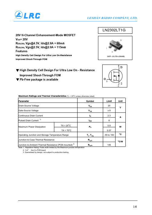
LN2302LT1G中文资料
Size 8 mm 12mm 16mm 24 mm
A Max
330mm (12.992’’) 330mm (12.992’’) 360mm (14.173’’) 360mm (14.173’’)
G
8.4mm+1.5mm, -0.0 (.33’’+.059’’, -0.00) 12.4mm+2.0mm, -0.0 (.49 ’’+ .079’’, -0.00) 16.4mm+2.0mm, -0.0 (.646’’+.078’’, -0.00) 24.4mm+2.0mm, -0.0 (.961’’+.070’’, -0.00)
▼ Pb-Free package is available
LN2302LT1G
3
1 2
SOT– 23 (TO–236AB)
3D
G 1 S 2
Maximum Ratings and Thermal Characteristics (TA = 25oC unless otherwise noted)
Parameter
VGS = 0V, ID = -10uA VGS = 4.5V, ID = 2.8A VGS = 2.5V, ID = 2.0A VDS =VGS, ID = 250uA VDS = 9.6V, VGS = 0V VGS = ±8V, VDS = 0V
VDS = 5V, ID = 4.0A
VDS = 6V, ID = 2.8A VGS = 4.5V
0.0177 0.0236 0.45
0.60
0.037 0.95
0.035 0.9
0.037 0.95
0.079 2.0
TK2019资料

THERMAL CHARACTERISTICS
TC2001
SYMBOL θJA
PARAMETER JunctFra bibliotekon-to-ambient Thermal Resistance (still air)
Value 80
UNITS °C/W
2
TK2019 – MC/2.1/10-03
元器件交易网
ELECTRICAL CHARACTERISTICS – TK2019
TA = 25 °C. See Application/Test Circuit. Unless otherwise noted, the supply voltage is VDD = 24V.
SYMBOL Iq IMUTE VIH VIL ISC IVPPSENSE PARAMETER Quiescent Current (No load, Mute = 0V) Mute Supply Current (No load, TC2001 Mute = 5V, TPS1035 Sleep = 5V) High-level input voltage (MUTE) Low-level input voltage (MUTE) Short circuit current limit VPPSENSE Threshold Currents CONDITIONS VDD = 24V V5 = 5V VDD = 24V V5 = 5V IIH = See Mute Control Section IIL = See Mute Control Section VDD = 24V, T=25oC Over-voltage turn on (muted) Over-voltage turn off (mute off) Under-voltage turn off (mute off) Under-voltage turn on (muted) Over-voltage turn on (muted) Over-voltage turn off (mute off) Under-voltage turn off (mute off) Under-voltage turn on (muted) 7.5 162 154 79 72 30.3 28.8 14.8 13.5 3.5 1.0 178 87 33.3 16.3 MIN. TYP. 20 27 2 7 MAX. 60 UNITS mA mA µA mA V V A µA µA µA µA V V V V
DG419DY芯片资料

_______________General DescriptionMaxim’s redesigned DG417/DG418/DG419 precision,CMOS, monolithic analog switches now feature guar-anteed on-resistance matching (3Ωmax) between switches and guaranteed on-resistance flatness over the signal range (4Ωmax). These switches conduct equally well in either direction and guarantee low charge injection, low power consumption, and an ESD tolerance of 2000V minimum per Method 3015.7.The new design offers low off-leakage current over temper-ature (less than 5nA at +85°C).The DG417/DG418 are single-pole/single-throw (SPST)switches. The DG417 is normally closed, and the DG418 is normally open. The DG419 is single-pole/double-throw (SPDT) with one normally closed switch and one normally open switch. Switching times are less than 175ns max for t ON and less than 145ns max for t OFF . Operation is from a single +10V to +30V supply, or bipolar ±4.5V to ±20V supplies. The improved DG417/DG418/DG419 are fabricated with a 44V silicon-gate process.________________________ApplicationsSample-and-Hold Circuits Communications Systems Test Equipment Battery-Operated Systems ModemsFax Machines Guidance and Control Systems PBX, PABX Audio Signal RoutingMilitary Radios______________________New Featureso Plug-In Upgrades for Industry-Standard DG417/DG418/DG419o Improved R DS(ON)Match Between Channels (3Ωmax, DG419 only)o Guaranteed R FLAT(ON)Over Signal Range (4Ωmax)o Improved Charge Injection (10pC max)o Improved Off-Leakage Current Over Temperature (<5nA at +85°C)o Withstand Electrostatic Discharge (2000V min)per Method 3015.7__________________Existing Featureso Low R DS(ON)(35Ωmax)o Single-Supply Operation +10V to +30V Bipolar-Supply Operation ±4.5V to ±20V o Low Power Consumption (35µW max)o Rail-to-Rail Signal Handling o TTL/CMOS-Logic CompatibleDG417/DG418/DG419Improved, SPST/SPDT Analog Switches________________________________________________________________Maxim Integrated Products 1_____________________Pin Configurations/Functional Diagrams/Truth Tables19-0114; Rev 2; 12/96* Contact factory for dice specifications.For free samples & the latest literature: , or phone 1-800-998-8800D G 417/D G 418/D G 419Improved, SPST/SPDT Analog SwitchesABSOLUTE MAXIMUM RATINGSELECTRICAL CHARACTERISTICS—Dual Supplies(V+ = +15V, V- = -15V, V L = 5V, GND = 0V, V INL = 0.8V, V INH = 2.4V, T A = T MIN to T MAX , unless otherwise noted.)Stresses beyond those listed under “Absolute Maximum Ratings” may cause permanent damage to the device. These are stress ratings only, and functional operation of the device at these or any other conditions beyond those indicated in the operational sections of the specifications is not implied. Exposure to absolute maximum rating conditions for extended periods may affect device reliability.Voltage Referenced to V-V+.......................................................................................44V GND....................................................................................25V VL..................................................(GND - 0.3V) to (V+ + 0.3V)Digital Inputs V S , V D (Note 1).........(V- - 2V) to (V+ + 2V) or 30mA(whichever occurs first)Continuous Current (any terminal) (Note 1)........................30mA Peak Current, S or D (pulsed at 1ms, 10% duty cycle max)..100mAContinuous Power Dissipation (T A = +70°C)Plastic DIP (derate 9.09mW/°C above +70°C).............727mW SO (derate 5.88mW/°C above +70°C)..........................471mW CERDIP (derate 8.00mW/°C above +70°C)..................640mW Operating Temperature RangesDG41_C_.............................................................0°C to +70°C DG41_D_..........................................................-40°C to +85°C DG41_AK........................................................-55°C to +125°C Storage Temperature Range.............................-65°C to +150°C Lead Temperature (soldering, 10sec).............................+300°CNote 1:Signals on S, D, or IN exceeding V+ or V- are clamped by internal diodes. Limit forward current to maximum current ratings.DG417/DG418/DG419Improved, SPST/SPDT Analog Switches_______________________________________________________________________________________3ELECTRICAL CHARACTERISTICS—Dual Supplies (continued)(V+ = +15V, V- = -15V, V L = 5V, GND = 0V, V INL = 0.8V, V INH = 2.4V, T A = T MIN to T MAX , unless otherwise noted.)D G 417/D G 418/D G 419Improved, SPST/SPDT Analog Switches 4_______________________________________________________________________________________ELECTRICAL CHARACTERISTICS—Single Supply(V+ = +12V, V- = 0V, VL = 5V, GND = 0V, V INH = 2.4V, V INL = 0.8V, T A = +25°C, unless otherwise noted.)Note 2:Typical values are for design aid only , are not guaranteed, and are not subject to production testing. The algebraicconvention where the most negative value is a minimum and the most positive value a maximum is used in this data sheet.Note 3:Guaranteed by design.Note 4:On-resistance match between channels and flatness is guaranteed only with bipolar-supply operation. Flatness is defined asthe difference between the maximum and the minimum value of on-resistance as measured at the extremes of the specified analog range.Note 5:Leakage parameters I S(OFF), I D(OFF), and I D(ON)are 100% tested at the maximum rated hot temperature and guaranteed bycorrelation at +25°C.Note 6:Off-Isolation Rejection Ratio = 20log (V D /V S ), V D = output, V S = input to off switch.Note 7:Between any two switches.DG417/DG418/DG419Improved, SPST/SPDT Analog Switches_______________________________________________________________________________________5__________________________________________Typical Operating Characteristics(T A = +25°C, unless otherwise noted.)455-20-1010ON-RESISTANCE vs. V D AND1535V D (V)R D S (O N ) (Ω)0202540103020505-20-1010ON-RESISTANCE vs. V D ANDTEMPERATURE30V D (V)R D S (O N ) (Ω)020201025153520515ON-RESISTANCE vs. V D (SINGLE SUPPLY)120V D (V)R D S (O N ) (Ω)102080401006014010515ON-RESISTANCE vs. V D ANDTEMPERATURE60V D (V)R D S (O N ) (Ω)10204020503070-60-20CHARGE INJECTION vs.ANALOG VOLTAGE40V D (V)Q (p C )0200-4020-2060-15-10-5510150.0001-75OFF-LEAKAGE CURRENT vs.TEMPERATURE10TEMPERATURE (°C)O F F -L E A K A G E (n A )251250.10.00110.011000.0001-75ON-LEAKAGE CURRENT vs.TEMPERATURE10TEMPERATURE (°C)O N -L E A K A G E (n A )251250.10.00110.011000.0001-75SUPPLY CURRENT vs.TEMPERATURE10TEMPERATURE (°C)I +, I -, I L (µA )251250.10.00110.01100D G 417/D G 418/D G 419__________Applications InformationOperation with Supply VoltagesOther than ±15VUsing supply voltages other than ±15V reduces the analog signal range. The DG417/DG418/DG419 switch-es operate with ±4.5V to ±20V bipolar supplies or with a +10V to +30V single supply; connect V- to 0V when operating with a single supply. Also, all device types can operate with unbalanced supplies, such as +24V and -5V. VL must be connected to +5V to be TTL com-patible, or to V+ for CMOS-logic level inputs. The Typical Operating Characteristics graphs show typical on-resistance with ±20V, ±15V, ±10V, and ±5V sup-plies. (Switching times increase by a factor of two or more for operation at ±5V.)Overvoltage ProtectionProper power-supply sequencing is recommended for all CMOS devices. Do not exceed the absolute maxi-mum ratings because stresses beyond the listed rat-ings may cause permanent damage to the devices.Always sequence V+ on first, followed by VL, V-, and logic inputs. If power-supply sequencing is not possi-ble, add two small, external signal diodes in series with the supply pins for overvoltage protection (Figure 1).Adding diodes reduces the analog signal range to 1V below V+ and 1V above V-, without affecting low switch resistance and low leakage characteristics. Device operation is unchanged, and the difference between V+ and V- should not exceed +44V.Improved, SPST/SPDT Analog Switches 6_____________________________________________________________________________________________________________________________________________________Pin DescriptionFigure 1. Overvoltage Protection Using External Blocking DiodesDG417/DG418/DG419Improved, SPST/SPDT Analog Switches_______________________________________________________________________________________7_____________________________________________________Test Circuits/Timing DiagramsFigure 2. DG417/DG418 Switching TimeFigure 3. DG419 Transition TimeD G 417/D G 418/D G 419Improved, SPST/SPDT Analog Switches 8_______________________________________________________________________________________Figure 5. Charge InjectionFigure 4. DG419 Break-Before-Make Interval______________________________________Test Circuits/Timing Diagrams (continued)DG417/DG418/DG419Improved, SPST/SPDT Analog Switches_______________________________________________________________________________________9Figure 6. Off-Isolation Rejection Ratio Figure 7. DG419 CrosstalkFigure 8. Drain-Source Off-CapacitanceFigure 9. Drain-Source On-Capacitance______________________________________Test Circuits/Timing Diagrams (continued)D G 417/D G 418/D G 419Improved, SPST/SPDT Analog Switches 10____________________________________________________________________________________________________________Chip Topography7645893210.058"1.47mm0.076"1.93mm__Ordering Information (continued)TRANSISTOR COUNT: 32SUBSTRATE CONNECTED TO V+* Contact factory for dice specifications.**Contact factory for availability and processing to MIL-STD-883B.DG419S GND V+VL IN V-S D DDG418N.C.GND V+VL IN V-S D N.C.DG417DIE PAD12D 3456GND 789V+VL IN V-N.C.N.C.SDG417/DG418/DG419Improved, SPST/SPDT Analog Switches________________________________________________________Package Informationimplied. Maxim reserves the right to change the circuitry and specifications without notice at any time.D G 417/D G 418/D G 419Improved, SPST/SPDT Analog Switches Maxim cannot assume responsibility for use of any circuitry other than circuitry entirely embodied in a Maxim product. No circuit patent licenses are 12__________________Maxim Integrated Products, 120 San Gabriel Drive, Sunnyvale, CA 94086 (408) 737-7600©1996 Maxim Integrated Products Printed USAis a registered trademark of Maxim Integrated Products.___________________________________________Package Information (continued)。
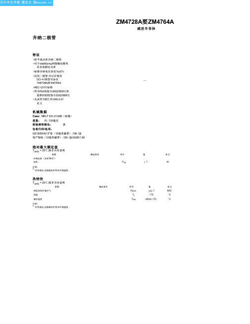
ZM4741A中文资料(vishay)中文数据手册「EasyDatasheet - 矽搜」
8.5
40
1000
0.25
ZM4752A
33
7.5
45
1000
0.25
ZM4753A
36
7
50
1000
0.25
ZM4754A
39
6.5
60
1000
0.25
ZM4755A
43
6
70
1500
0.25
ZM4756A
47
5.5
80
1500
0.25
ZM4757A
51
5
95
1500
0.25
ZM4758A
56
4.5
绝对最大额定值
Tamb = 25℃,除非另有说明
参数
齐纳电流(见表"特色")
功耗
注意:
1) 有效规定,电极被防护持在环境温度.
热特性
Tamb = 25℃,除非另有说明
参数 热阻结到环境空气 结温 储存温度
注意:
1) 有效规定,电极被防护持在环境温度.
测试条件 测试条件
18315
符号
值
单元
Ptot
1 1)
18317
6.50 (0.256) ref.
min. 3.00 (0.118)
芯片中文手册,看全文,戳
法律免责声明
免责声明
所有产品规格及数据如有更改,恕不另行通知. Vishay Intertechnology,Inc.宣布,其附属公司,代理商和员工,以及代表及其或其各自所有人(统称为" Vishay"),对本文包含任何错误,不准确或不完整或以任何其他方式披露不承担任何责任有关任何产品.
2N4117A中文资料(Calogic)中文数据手册「EasyDatasheet - 矽搜」

Part
Hale Waihona Puke 包裹2N4117-19 / A密封TO-72 PN4117-19 / A塑料TO-92 SST4117-19塑料SOT-23 X2N4117-19 / A排序芯片载体
温度范围
-55oC至175 oC -55oC至+135 oC -55oC至+135 oC -55oC至175 oC
电气特性
(TA = 25 oC除非另有说明)
(TA = 25oC除非另有说明)
门源或门极 - 漏极电压. . . . . . . . . . . . . . . . -40V
栅电流. . . . . . . . . . . . . . . . . . . . . . . . . . . . . . . . . 50毫安
存储温度范围. . . . . . . . . . . . . -65
芯片中文手册,看全文,戳
N沟道JFET
通用放大器
LLC
引脚配置
5007
2N4117 – 2N4119 / 2N4117A – 2N4119A PN4117 – PN4119 / PN4117A – PN4119A / SST4117 – SST4119
特征
低 电 容漏 出
Low
绝对最大额定值
最小值最大值最小值最大值最小值最大值
测试条件
-40
-40
-40
V IG = -1µA, V DS = 0
-10
-10
-10
pA
-1
-1
-1
VGS = -20V, V DS = 0
-25
-25
-25
nA
-2.5
-2.5
BTS 4141D中文资料

Page 4
2004-01-27
元ical Characteristics Parameter at Tj = -40...125 °C, Vbb = 15...30 V unless otherwise specified Operating Parameters Operating voltage Undervoltage shutdown Undervoltage restart Undervoltage hysteresis ∆Vbb(under) = Vbb(u rst) - Vbb(under) Standby current Tj = -40...85 °C, V IN ≤ 1,2 V Tj = 125 °C1) Operating current Leakage output current (included in Ibb(off)) VIN ≤ 1,2 V Protection Functions2) Initial peak short circuit current limit Tj = -40 °C, Vbb = 20 V, tm = 150 µs Tj = 25 °C Tj = 125 °C Repetitive short circuit current limit Tj = Tjt (see timing diagrams) Output clamp (inductive load switch off) at VOUT = Vbb - VON(CL), I bb = 4 mA Overvoltage protection 3) Ibb = 4 mA Thermal overload trip temperature 4) Thermal hysteresis Tjt ∆Tjt 135 10 °C K VON(CL) Vbb(AZ) 47 47 52 V IL(SCr) IL(SCp) 0.7 1.4 1.1 2.1 A IGND IL(off) Ibb(off) 10 1 3.5 25 50 1.6 10 mA µA µA Vbb(on) Vbb(under) Vbb(u rst) ∆Vbb(under) 12 7 0.5 45 10.5 11 V Symbol min. Values typ. max. Unit
MN101EF29G中文资料
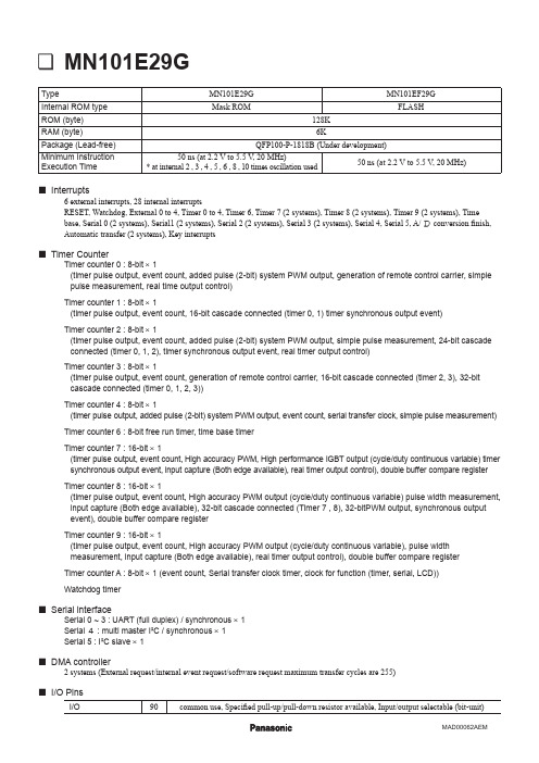
10-bit × 16-ch.
Display control function
LCD 55 segments × 4 commons (static, 1/2, 1/3, 1/4 duty) 1/3 bias, Usable if VLC1 ≤ VDD Buzzer output, remote control carrier signal output, high-current drive port Correcting address designation : up to 7 addresses possible In-circuit Emulator PX-ICE101E + PRBV101E29-QFP100-P-1818B (Under development)
Serial interface
Serial 0 ~ 3 : UART (full duplex) / synchronous × 1 Serial 4 : multi master I²C / synchronous × 1 Serial 5 : I²C slave × 1 2 systems (External request/internal event request/software request maximum transfer cycles are 255)
MN101E29G
Type Internal ROM type ROM (byte) RAM (byte) Package (Lead-free) Minimum Instruction Execution Time MN101E29G Mask ROM 128K 6K QFP100-P-1818B (Under development) 50 ns (at 2.2 V to 5.5 V, 20 MHz) 50 ns (at 2.2 V to 5.5 V, 20 MHz) * at internal 2 , 3 , 4 , 5 , 6 , 8 , 10 times oscillation used MN101EF29G FLASH
半导体器件芯片常用型号参数12页word文档
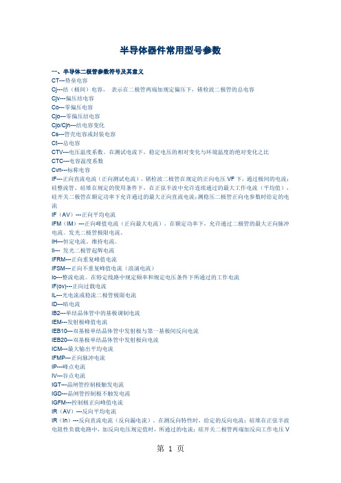
半导体器件常用型号参数一、半导体二极管参数符号及其意义CT---势垒电容Cj---结(极间)电容,表示在二极管两端加规定偏压下,锗检波二极管的总电容Cjv---偏压结电容Co---零偏压电容Cjo---零偏压结电容Cjo/Cjn---结电容变化Cs---管壳电容或封装电容Ct---总电容CTV---电压温度系数。
在测试电流下,稳定电压的相对变化与环境温度的绝对变化之比CTC---电容温度系数Cvn---标称电容IF---正向直流电流(正向测试电流)。
锗检波二极管在规定的正向电压VF下,通过极间的电流;硅整流管、硅堆在规定的使用条件下,在正弦半波中允许连续通过的最大工作电流(平均值),硅开关二极管在额定功率下允许通过的最大正向直流电流;测稳压二极管正向电参数时给定的电流IF(AV)---正向平均电流IFM(IM)---正向峰值电流(正向最大电流)。
在额定功率下,允许通过二极管的最大正向脉冲电流。
发光二极管极限电流。
IH---恒定电流、维持电流。
Ii--- 发光二极管起辉电流IFRM---正向重复峰值电流IFSM---正向不重复峰值电流(浪涌电流)Io---整流电流。
在特定线路中规定频率和规定电压条件下所通过的工作电流IF(ov)---正向过载电流IL---光电流或稳流二极管极限电流ID---暗电流IB2---单结晶体管中的基极调制电流IEM---发射极峰值电流IEB10---双基极单结晶体管中发射极与第一基极间反向电流IEB20---双基极单结晶体管中发射极向电流ICM---最大输出平均电流IFMP---正向脉冲电流IP---峰点电流IV---谷点电流IGT---晶闸管控制极触发电流IGD---晶闸管控制极不触发电流IGFM---控制极正向峰值电流IR(AV)---反向平均电流IR(In)---反向直流电流(反向漏电流)。
在测反向特性时,给定的反向电流;硅堆在正弦半波电阻性负载电路中,加反向电压规定值时,所通过的电流;硅开关二极管两端加反向工作电压VR时所通过的电流;稳压二极管在反向电压下,产生的漏电流;整流管在正弦半波最高反向工作电压下的漏电流。
屹晶微电子 EG4002 微波、红外感应处理芯片数据手册说明书

版本变更记录版本号日期描述V1.0 2012年11月13日EG4002数据手册初稿V1.1 2013年03月26日添加光敏电阻应用图V1.2 2013年04月26日更新光敏电阻应用图V1.3 2019年12月02日添加DFN8封装目录1. 特性 (1)2. 描述 (1)3. 应用领域 (1)4. 引脚 (2)4.1 引脚定义 (2)4.2 引脚描述 (2)5. 结构框图 (3)6. 典型应用电路 (3)6.1 EG4002典型应用电路图 (3)6.2 EG4002控制继电器应用电路图 (4)6.3 EG4002可重复触发+光敏电阻应用电路图 (4)6.4 EG4002可重复触发+光敏电阻微波方案应用电路图 (5)7. 电气特性 (5)7.1 极限参数 (5)7.2 典型参数 (6)8. 应用设计 (7)8.1 振荡器工作频率计算 (7)8.2 触发延时时间定时器和触发封锁时间定时器 (7)8.3 A端重复和不可重复触发功能 (8)8.4 Vc触发禁止端 (8)8.5 第一级运放增益设定 (9)9. 封装尺寸 (9)9.1 DIP8封装尺寸 (9)9.2 SOP8封装尺寸 (10)9.3 DFN8封装尺寸 (10)EG4002芯片数据手册V1.31. 特性⏹8引脚微波、红外感应专用芯片,外围电路简单,成本低⏹静态功耗小,3V工作电源时功耗小于45uA, 5V工作电源时功耗小于75uA,非常适合电池供电系统应用⏹高输入阻抗运算放大器,可与多种传感器匹配,进行信号与处理⏹双向鉴幅器,可有效抑制干扰⏹内置参考电压,供内部比较器和运放的参考电压⏹内设延时时间定时器和封锁时间定时器,改变振荡器频率即可设定定时延时时间⏹外围元器件少,只需配置第一级运放的增益和振荡器的RC器件即能可靠工作⏹工作电源+3V~+6V⏹封装形式: SOP8、DFN8、DIP82. 描述EG4002是一款专为微波、红外信号放大及处理输出的数模混合专用芯片,内部集成了运算放大器、双门限电压比较器、参考电压源、延时时间定时器和封锁时间定时器及状态控制器等,专用于防盗报警系统、人体门控制装置、照明控制开关等场合。
STK4192II中文资料
VCC = ±42V
min
typ
max
20
40
100
50
55
0.3
20 to 50k
55
1.2
–70
0
+70
–2
–5
–10
Unit mA W
W % Hz kΩ mVrms mV V
Notes.
For power supply at the time of test, use a constant-voltage power supply unless otherwise specified. For measurement of the available time for load short-circuit and output noise voltage, use the specified transformer power supply shown right. The output noise voltage is represented by the peak value on rms scale (VTVM) of average value indicating type. For AC power supply, use an AC stabilized power supply (50Hz) to eliminate the effect of flicker noise in AC primary line.
Resistors for input filter
Sample Printed Circuit Pattern for Application Circuit (Cu-foiled side)
No. 2305—3/8
屹晶微电子EG2181芯片数据手册说明书

ELECTRONIC GIANT EG2181芯片数据手册大功率MOS管、IGBT管栅极驱动芯片版本变更记录目录1. 特点 (4)2. 描述 (4)3. 应用领域 (4)4. 引脚 (5)4.1. 引脚定义 (5)4.2. 引脚描述 (5)5. 结构框图 (6)6. 典型应用电路 (6)7. 电气特性 (7)7.1 极限参数 (7)7.2 典型参数 (8)7.3 开关时间特性及死区时间波形图 (9)8. 应用设计 (10)8.1Vcc端电源电压 (10)8.2输入逻辑信号要求和输出驱动器特性 (10)8.3自举电路 (11)9. 封装尺寸 (12)9.1 SO8封装尺寸 (12)EG2181芯片数据手册V1.01. 特点⏹高端悬浮自举电源设计,耐压可达600V⏹适应5V、3.3V输入电压⏹最高频率支持500KHZ⏹低端VCC电压范围3.5V-20V⏹输出电流能力I O+/- 2A/2.5A⏹内建死区控制电路⏹自带闭锁功能,彻底杜绝上、下管输出同时导通⏹HIN输入通道高电平有效,控制高端HO输出⏹LIN输入通道高电平有效,控制低端LO输出⏹外围器件少⏹静态电流小于5uA,非常适合电池场合⏹封装形式:SOP-82. 描述EG2181是一款高性价比的大功率MOS管、IGBT管栅极驱动专用芯片,内部集成了逻辑信号输入处理电路、死区时控制电路、闭锁电路、电平位移电路、脉冲滤波电路及输出驱动电路,专用于无刷电机控制器中的驱动电路。
EG2181高端的工作电压可达600V,低端Vcc的电源电压范围宽3.5V~20V,静态功耗小于5uA。
该芯片具有闭锁功能防止输出功率管同时导通,输入通道H IN和L IN内建了一个200K下拉电阻,在输入悬空时使上、下功率MOS管处于关闭状态,输出电流能力I O+/- 2/2.5A,采用SOP8封装。
3. 应用领域⏹移动电源高压快充开关电源⏹变频水泵控制器⏹600V降压型开关电源⏹电动车控制器⏹无刷电机驱动器⏹高压Class-D类功放4. 引脚4.1. 引脚定义IN IN图4-1. EG2181管脚定义4.2. 引脚描述5. 结构框图H LOGNDVccHOVS VBL图5-1. EG2181结构框图6. 典型应用电路+600VH L OUT图6-1. EG2181典型应用电路图7. 电气特性7.1 极限参数7.2 典型参数无另外说明,在A25℃,Vcc=12V,负载电容C L=10nF条件下7.3开关时间特性及死区时间波形图图7-1. 低端输出LO 开关时间波形图 图7-2. 高端输出HO 开关时间波形图50%50%LOH INLINHO 50%50%图7-3. 死区时间波形图8. 应用设计8.1 Vcc 端电源电压针对不同的MOS 管,选择不同的驱动电压,高压开启MOS 管推荐电源Vcc 工作电压典型值为10V-15V ;低压开启MOS 管推荐电源VCC 工作电压3.5V-10V 。
屹晶微电子 EG1162 芯片数据手册说明书
2019©屹晶微电子有限公司 版权所有
1/1
屹晶微电子有限公司
EG1162 芯片数据手册 V1.0
高压大电流降压型开关电源芯片
EG1162 芯片数据手册 V1.0
1. 特性
降压同步整流方案,支持高压大电流方案。 外接一个电容可设置工作频率(0-300KHz) 2 脚 EN 外部电阻可灵活调整启动、关闭电压 UVLO 欠压锁定功能:
2019©屹晶微电子有限公司 版权所有
1/1
屹晶微电子有限公司
EG1162 芯片数据手册 V1.0
高压大电流降压型开关电源芯片
目录
1. 特性 ..................................................................................................................................................................... 1 2. 描述 ..................................................................................................................................................................... 1 3. 应用领域 ............................................................................................................................................................. 1 4. 引脚 ..................................................................................................................................................................... 2
RC4190资料

125 70 150
375 4.17 6.25 8.33
mA mW/°C mW/°C mW/°C
Operating Conditions
Parameter θJC θJA Thermal resistance Thermal resistance CerDIP SOIC PDIP CerDIP Min Typ 45 200 160 120 Max Units °C/W °C/W °C/W °C/W
3
PRODUCT SPECIFICATION
பைடு நூலகம்
RC4190
Electrical Characteristics
(+VS = +6.0V, IC = 5.0 µA, and TA = +25°C unless otherwise noted.) RM4190 Symbol +VS VREF ISW ISY ef Parameters Supply Voltage Reference Voltage (Internal) Switch Current Supply Current Efficiency Line Regulation LI FO IC ICO Load Regulation Operating Frequency Range Reference Set Current Switch Leakage Current Supply Current (Disabled) Low Battery Bias Current Capacitor Charging Current Oscillator Frequency Tolerance +VTHX -VTHX IFB ILBD Capacitor Threshold Voltage + Capacitor Threshold Voltage – Feedback Input Current Low Battery Output Current V7 = 1.3V V8 = 0.4V, V1 = 1.1V 500 V4 = 24V (RC4190) 30V (RM4190, RC4190A) VC ≤ 200 mV V1 = 1.2V 0.5 VOUT < VS < VOUT VS = +0.5 VOUT PL = 150 mW 0.1 1.0 V4 = 400 mV Measure at Pin 5 I4 = 0 Conditions Min 2.2 1.29 100 1.31 200 215 85 0.04 0.2 25 5.0 0.01 0.2 0.5 75 50 5.0 0.1 1.0 300 Typ Max 30 1.33 Min 2.2 1.24 100 1.31 200 215 85 0.04 0.2 25 5.0 0.01 0.5 0.5 75 50 5.0 300 RC4190 Typ Max 24 1.38 Units V V mA µA % % VO % VO kHz µA µA
【doc】用STK4191制作的功率放大器

用STK4191制作的功率放大器陈启新本文向又家介绍一种用厚膜集成电路组装的大功率扩音机.该机的核心器件是STK191.STKd191是日本三洋公司厚膜集成电路系列产品中的新品种.它的内电路是典型的OCL功放电路,与其它厚膜电路的区剐是STK4191内部设计了开关机延时电路,从而捎腺了开关机噪声.STK191的工作电压较高,所l捌象出功率较大.此外和STK4191同一系列的STK4151与STK4191内电路完垒一样,只是工作电压稍低.甩STK4TL~'I翩作鹄立体声扩音机电路如附躅所示STKd191由两个完垒对称的OCL电路组成.电譬中第1脚,第2脚是差动放大器的两个输^端,音频信号从第1脚输入,负反缋信号从第2脚输入,改变R,R.,可以改变放大器的增箍,第10脚是辐出端两个声道的工作情况完垒一致OCL电路的工作原理这里就不详述了.下面谈谈选个扩音机的保护电路.由于大功率扩音机的工作电压较高,若输出端发生短路,将会拥坏扬声器为此本扩音机装上了功能完善的保护电瞎.过琉保护电路中,检流电阻是R…R?(0—50).当扩音机出现短路或过载现象时,有很大的电疏通过R…R…电阻上的鹾降增大,位BG,BG盛BGa,BG"导通(视正负半周信号而定),它们的集电极电位下降,井通过电阻Ra(5.IkD)触发BG,BG,杓成的双稳态电路,使BG导通,将C川短路,切断了STK4191的前最级电源.从而保护集成电路和扬声器.电容器CCCC使保护电路对瞬志大幅度信号不作喻应.在由BGt,BG,构成的双稳志电路中,C远大于C1,故每次开机时BG:均截止.BG也截止,C-,Rll,RR.,Rl.等是STKd191推荐电路中的防冲击网络.D-的作用是在关机时迅速泄拔Cc..E的屯压,使奖机时无冲击.保护1980午第7期电路动作后,只要排磕故障,再启电源即可L作.另外,反馈电阻R:,R?'56J)直{.STK4191的输出端,而是与RI,t,按扬.端相接.选种接珐的好处是使R…it.处干懦内,对本机的阻尼系数影响甚微过热保护电j!{:中:n 感温元件是BG…它紧贴干散热片正常时hG,不导通.当温度高时BG的be衄电净,当B,GJ问电压低于由RR.设定的电J-¨-使G.通,BG,BG截止,切断向载实现t热保护当srK191辐出端出现较高的电位啊.B…BG…导通,BG;,BG.截fl:,扬声器得出保.××邮购消息广西悟州市玉电器』一(梧州l大未上路15号)邮售t(Dl$文介研岣俯垒护STKd191功放扳I4元/件.圆骷垒铩护s"{tl1功效扳115元/件.@配台扩音拢i的1L082前.订镣均衡器双5段67元/份j双7蛩元/协一般:J段87 元/份,配420×85面板】4元仲jfir档台邮器开户行;北环办帐号101l一7185教到十内发货。
线性隔离器ADuM4190_cn

应用
线性反馈电源 逆变器 不间断电源(UPS) DOSA兼容模块 电压监控器
功能框图
VDD1 1 GND1 2 VREG1 3 REFOUT1 4
NC 5 EAOUT2 6 EAOUT 7
GND1 8
REG UVLO REF
精密电路工作原理 ................................................................ 13 隔离式放大器电路工作原理 .............................................. 14 应用框图 ................................................................................. 14 设置输出电压 ........................................................................ 15 DOSA模块应用 ..................................................................... 15 直流正确性和磁场抗扰度 ................................................... 15 隔离寿命.................................................................................. 16 外形尺寸 ...................................................................................... 17 订购指南.................................................................................. 17
RN8209-SSOP24-天高微 单相计量芯片
1、 关闭MCU全局中断和/INT中断; 2、 MCU通过串口读RIF寄存器,清IF和RIF寄存器,将IRQ恢复到高电平; 3、 MCU通过判断RIF的中断标志来判断RN8209的中断源,转而执行相应的中断
处理程序;在此过程中,RN8209若发生新的中断事件,IF相关标志置位, IRQ也会由高变低,触发MCU的/INT中断标志置位,记录了此事件;
CS 上升沿之间的时间间隔 t2 要大于等于半个 SCLK 周期。
注意:有写保护功能的寄存器在写操作之前要先写入写使能命令。
4. 4. 4、SPI 读操作
MCU 在 CS 有效后,先通过 SPI 写入命令字节(8bit,包含寄存器地址),RN8209收 到读命令后,在 SCLK 的上升沿将数据按位从 SDO 引脚输出。
3. 在最后一个比特移出 SDO 后,CS 由低至高时将 RIF 寄存器的内容和 IF 同步。
除了读 RIF 寄存器操作,其他情况下 IF 和 RIF 都保持一致。为了在 SPI 读中断标志 过程中不丢失中断,在中断处理程序中推荐用户使用 RIF 寄存器。
版本:Ver 1.0
第 5 页 共 24 页
用于电压采样。ADC 采用全差分方式输入,电流、电压通道最大信号输入幅度峰值为 660mV。芯片测量三个通道的真有效值参数输出,提供两路有功功率、无功功率的计算 和校正。同时提供频率测量、过零检测和能量脉冲输出。 4. 2、能量脉冲输出
RN8209带有专用的有功、无功能量的脉冲输出端口 PF、QF,可以通过这两个端口直 接进行误差比对。PF/QF 输出满足下面的时序关系:
2、功能框图与引脚说明
2. 1、功能框图
版本:Ver 1.0
第 1 页 共 2ቤተ መጻሕፍቲ ባይዱ 页
- 1、下载文档前请自行甄别文档内容的完整性,平台不提供额外的编辑、内容补充、找答案等附加服务。
- 2、"仅部分预览"的文档,不可在线预览部分如存在完整性等问题,可反馈申请退款(可完整预览的文档不适用该条件!)。
- 3、如文档侵犯您的权益,请联系客服反馈,我们会尽快为您处理(人工客服工作时间:9:00-18:30)。
61197HA (ID) / 8298MO / 4085KI No. 1651—1/5
元器件交易网
STK4191V
Operating Characteristics at Ta = 25°C, VCC = ±35.5V, RL = 8Ω (non-inductive), Rg = 600Ω, VG = 40 dB unless otherwise specified, at specified test circuit (based on sample application circuit)
• Built-in muting circuit to cut off various kinds of pop noise.
• Greatly reduced heat sink due to substrate temperature 125°C guaranteed.
• Distortion 0.08% due to current mirror circuit. • Pin-compatible with the STK4101II series. The
STK4101V series use the same package and are available for output 6W to 50W. • Excellent cost performance.
unit: mm 4040
[STK4191V]
Specifications Maximum Ratings at Ta = 25°C
STK4191V
Output power, PO - W
Frequency, f - Hz
s No products described or contained herein are intended for use in surgical implants, life-support systems, aerospace equipment, nuclear power control systems, vehicles, disaster/crime-prevention equipment and the like, the failure of which may directly or indirectly cause injury, death or property loss.
s Anyone purchasing any products described or contained herein for an above-mentioned use shall: Accept full responsibility and indemnify and defend SANYO ELECTRIC CO., LTD., its affiliates, subsidiaries and distributors and all their officers and employees, jointly and severally, against any and all claims and litigation and all damages, cost and expenses associated with such use: Not impose any responsibility for any fault or negligence which may be cited in any such claim or litigation on SANYO ELECTRIC CO., LTD., its affiliates, subsidiaries and distributors or any of their officers and employees, jointly or severally.
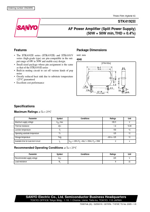
Parameter Maximum supply voltage Thermal resistance Junction temperature Operating substrate temperature Storage temperature Available time for load short-circuit
Equivalent Circuit
Specified transformer power supply (Equivalent to MG-200)
No. 1651—2/5
元器件交易网
STK4191V
Sample Application Circuit : 50W min AF Power Amplifier (2 channels)
元器件交易网
Ordering number: EN1651B
Thick Film Hybrid IC
STK4191 V
AF Power Amplifier (Split Power Supply) (50W + 50W min, THD = 0.08%)
Features
Package Dimensions
Symbol ICCO PO (1)
PO (2) THD fL, fH
ri VNO VN VM
Conditions
VCC = ±42.5V
f = 20Hz to 20kHz, THD = 0.08%
VCC = ±32V, f = 1kHz, THD = 0.2%, RL = 4Ω
f = 1kHz, Po = 1W
Symbol VCC max
θj-c Tjmax
Tc Tstg
ts
Conditions VCC = ±35.5V, RL = 8Ω, f = 50Hz, PO = 50W
Ratings ±53 1.8 150 125
−30 to +125 2
Unit V
°C/W °C °C °C s
Recommended Operating Conditions at Ta = 25°C
This catalog provides information as of June, 1997. Specifications and information herein are subject to change without notice.
No. 1651—5/5
Parameter Quiescent current
Output power
Total harmonic distortion Frequency response Input impedance Output noise voltage Neutral voltage Muting voltage
Parameter Recommended supply voltage Load resistance
Symbol VCC RL
Conditions
Ratings
Unit
±35.5
V
8
Ω
SANYO Electric Co., Ltd. Semiconductor Business Headquarters
STK4191Vltage, VCC - V
Supply voltage, VCC - V No. 1651—4/5
QNuieusctreanltvcoulrtaregnet,,VIcNco- m- mVA
元器件交易网
s Information (including circuit diagrams and circuit parameters) herein is for example only; it is not guaranteed for volume production. SANYO believes information herein is accurate and reliable, but no guarantees are made or implied regarding its use or any infringements of intellectual property rights or other rights of third parties.
Output power, PO - W
Output power, PO - W
QNuieusctreanltvcoulrtaregnet,,VIcNco- m- mVA Output power, PO - W
Quiescent current, ICCO - mA
Total harmonic distortion, THD - %
PO
=
1W,
+0 −3
dB
f = 1kHz, PO = 1W
VCC = ±42.5V, Rg = 10kΩ
VCC = ±42.5V
min
typ
max
20
40
100
50
55
0.08
20 to 50k
55
1.2
-70
0
+70
-2
-5
-10
Unit mA W
W % Hz kΩ mVrms mV V
Note : For Power supply at the time of test, use a constant-voltage power supply unless otherwise specified.
Voltage gain, VG - dB
Voltage gain, VG - dB
Output power, PO - W
Frequency, f - Hz
Frequency, f - Hz
