E54-CT1;E53-COV08;E53-COV0809;E53-Q;E53-Q3;中文规格书,Datasheet资料
XC7VX485T-1FFG1157I
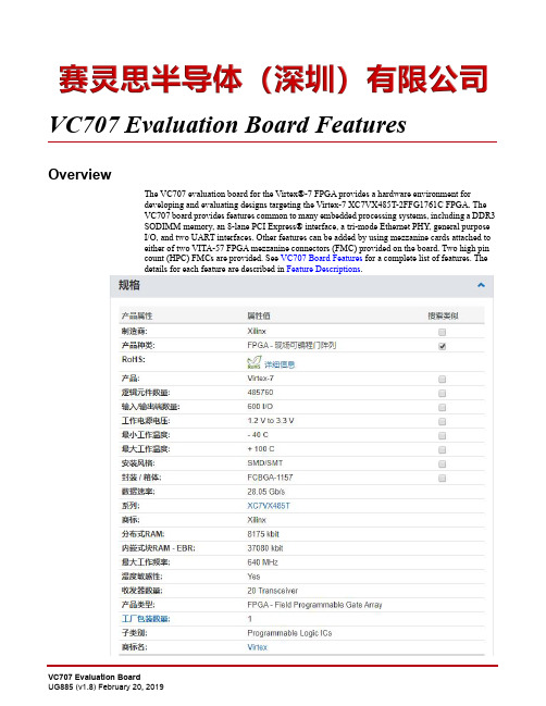
VC707 Evaluation Board FeaturesOverviewThe VC707 evaluation board for the Virtex®-7FPGA provides a hardware environment fordeveloping and evaluating designs targeting the Virtex-7 XC7VX485T-2FFG1761C FPGA. TheVC707 board provides features common to many embedded processing systems, including a DDR3SODIMM memory, an 8-lane PCI Express® interface, a tri-mode Ethernet PHY, general purposeI/O, and two UART interfaces. Other features can be added by using mezzanine cards attached toeither of two VITA-57 FPGA mezzanine connectors (FMC) provided on the board. Two high pincount (HPC) FMCs are provided. See VC707 Board Features for a complete list of features. Thedetails for each feature are described in Feature Descriptions.8U34I 2C programmable user clock LVDS,156.250MHz default frequency (back side of board)Silicon Labs SI570BAB0000544DG 329J31, J32User SMA clockRosenberger 32K10K-400L53210J25, J26GTX transceiver SMA reference clock Rosenberger 32K10K-400L53211U24Jitter attenuated clock (back side of board)Silicon Labs SI5324C-C-GM 3312GTX transceiver Quad 111 – Quad 119Embedded within FPGA U112 – 1513P1PCI Express connector 8-lane card edge connector 3014P3SFP/SFP+ module connector Molex 74441-00103115U5010/100/1000 Mb/s Ethernet PHY Marvell M88E1111-BAB1C0003416U2SGMII GTX transceiver clock generator ICS ICS84402IAGI-01LF 3217U44USB-to-UART bridgeSilicon Labs CP2103GM 3618P2, U48HDMI video connector, HDMI controller Molex 500254-1927, AD ADV7511KSTZ-P 43, 4219J23LCD character display and connector 2x 7 0.1 inch male header 3920U52I 2C Bus Switch (back side of board)TI PCA9548ARGER 4121DS11–DS13Ethernet status LEDs EPHY status LED, dual green 3422DS2–DS9User LEDsGPIO LEDs, green 06033823SW3–SW7User pushbuttons, active-High E-Switch TL3301EP100QG 3824SW2User DIP Switch8-pole C and K SDA08H1SBD 3825SW10User rotary switch (under LCD assembly)Panasonic EVQ-WK40013826J33, J34User SMA GPIO Rosenberger 32K10K-400L53227SW12Power on/off switch C&K 1201M2S3AQE24528SW9FPGA PROG pushbuttonE-Switch TL3301EP100QG 3829SW11Config mode/upper linear flash address dip switch 5-pole C&K SDA05H1IBD 3630J35FMC HPC1 connector (J35)Samtec ASP_134486_0122–2531J37FMC HPC2 connector (J37)Samtec ASP_134486_0126–2932Power management system (front and back side of board)TI UCD9248PFC in conjunction with various regulators 45–5533J19Xilinx XADC header 2x 10 0.1inch male header 4034J27, J28GTX receiver SMA (RX) Rosenberger 32K10K-400L53235J29/J30GTX transmitter SMA (TX)Rosenberger 32K10K-400L53236J5 2 x 5 shrouded PMBus connector Assman HW10G-0202 4637J1812V power input 2 x 3 connectorMolex 39-30-106046Table 1-1:VC707 Board Component Descriptions (Cont’d)CalloutReference Designator Component DescriptionNotesSchematic 0381418 Page NumberNet Name FPGA (U1)PinPCIe Edge Connector (P1)FunctionFHG1761Placement Pin NamePCIE_RX0_P Y4B14PETp0Integrated Endpoint block receive pair GTXE2_CHANNEL_X1Y11 PCIE_RX0_N Y3B15PETn0Integrated Endpoint block receive pair GTXE2_CHANNEL_X1Y11 PCIE_RX1_P AA6B19PETp1Integrated Endpoint block receive pair GTXE2_CHANNEL_X1Y10 PCIE_RX1_N AA5B20PETn1Integrated Endpoint block receive pair GTXE2_CHANNEL_X1Y10 PCIE_RX2_P AB4B23PETp2Integrated Endpoint block receive pair GTXE2_CHANNEL_X1Y9 PCIE_RX2_N AB3B24PETn2Integrated Endpoint block receive pair GTXE2_CHANNEL_X1Y9 PCIE_RX3_P AC6B27PETp3Integrated Endpoint block receive pair GTXE2_CHANNEL_X1Y8Feature DescriptionsPCIE_RX3_N AC5B28PETn3Integrated Endpoint block receive pair GTXE2_CHANNEL_X1Y8PCIE_RX4_P AD4B33PETp4Integrated Endpoint block receive pair GTXE2_CHANNEL_X1Y7PCIE_RX4_N AD3B34PETn4Integrated Endpoint block receive pair GTXE2_CHANNEL_X1Y7PCIE_RX5_P AE6B37PETp5Integrated Endpoint block receive pair GTXE2_CHANNEL_X1Y6PCIE_RX5_N AE5B38PETn5Integrated Endpoint block receive pair GTXE2_CHANNEL_X1Y6PCIE_RX6_P AF4B41PETp6Integrated Endpoint block receive pair GTXE2_CHANNEL_X1Y5PCIE_RX6_N AF3B42PETn6Integrated Endpoint block receive pair GTXE2_CHANNEL_X1Y5PCIE_RX7_P AG6B45PETp7Integrated Endpoint block receive pair GTXE2_CHANNEL_X1Y4PCIE_RX7_N AG5B46PETn7Integrated Endpoint block receive pair GTXE2_CHANNEL_X1Y4PCIE_TX0_P W2A16PERp0Integrated Endpoint block transmit pair GTXE2_CHANNEL_X1Y11PCIE_TX0_N W1A17PERn0Integrated Endpoint block transmit pair GTXE2_CHANNEL_X1Y11PCIE_TX1_P AA2A21PERp1Integrated Endpoint block transmit pair GTXE2_CHANNEL_X1Y10PCIE_TX1_N AA1A22PERn1Integrated Endpoint block transmit pair GTXE2_CHANNEL_X1Y10PCIE_TX2_P AC2A25PERp2Integrated Endpoint block transmit pair GTXE2_CHANNEL_X1Y9PCIE_TX2_N AC1A26PERn2Integrated Endpoint block transmit pair GTXE2_CHANNEL_X1Y9PCIE_TX3_P AE2A29PERp3Integrated Endpoint block transmit pair GTXE2_CHANNEL_X1Y8PCIE_TX3_N AE1A30PERn3Integrated Endpoint block transmit pair GTXE2_CHANNEL_X1Y8PCIE_TX4_P AG2A35PERp4Integrated Endpoint block transmit pair GTXE2_CHANNEL_X1Y7PCIE_TX4_N AG1A36PERn4Integrated Endpoint block transmit pair GTXE2_CHANNEL_X1Y7PCIE_TX5_P AH4A39PERp5Integrated Endpoint block transmit pair GTXE2_CHANNEL_X1Y6PCIE_TX5_N AH3A40PERn5Integrated Endpoint block transmit pair GTXE2_CHANNEL_X1Y6PCIE_TX6_P AJ2A43PERp6Integrated Endpoint block transmit pair GTXE2_CHANNEL_X1Y5PCIE_TX6_N AJ1A44PERn6Integrated Endpoint block transmit pair GTXE2_CHANNEL_X1Y5PCIE_TX7_P AK4A47PERp7Integrated Endpoint block transmit pair GTXE2_CHANNEL_X1Y4PCIE_TX7_N AK3A48PERn7Integrated Endpoint block transmit pair GTXE2_CHANNEL_X1Y4Si5324_OUT_C_P AD8A13REFCLK+Integrated Endpoint block differential clock pairfrom PCIeMGT_BANK_114(not Quad 115)Si5324_OUT_C_N AD7A14REFCLK-Integrated Endpoint block differential clock pair from PCIeMGT_BANK_114(not Quad 115)PCIE_PRSNT_B J49 2, 4, 6A1PRSNT#1J49 Lane Size Select jumperNA PCIE_WAKE_B A V33B11WAKE#Integrated Endpoint block wake signal, not connected on KC705 BoardNA PCIE_PERST_BA V35A11PERSTIntegrated Endpoint block reset signalNANet Name FPGA (U1)Pin PCIe Edge Connector (P1)FunctionFHG1761PlacementPin Name质量等级领域:宇航级IC 、特军级IC 、超军级IC 、普军级IC 、禁运IC 、工业级IC ,军级二三极管,功率管等;应用领域:航空航天、船舶、汽车电子、军用计算机、铁路、医疗电子、通信网络、电力工业以及大型工业设备祝您:工作顺利,生活愉快!以赛灵思半导体(深圳)有限公司提供的参数为例,以下为XC7VX485T-1FFG1157I的详细参数,仅供参考。
SIMATIC NET 工业以太网交换机 SCALANCE XC-200 操作说明说明书

SIMATIC NET工业以太网交换机SCALANCE XC-200操作说明02/2023法律资讯警告提示系统为了您的人身安全以及避免财产损失,必须注意本手册中的提示。
人身安全的提示用一个警告三角表示,仅与财产损失有关的提示不带警告三角。
警告提示根据危险等级由高到低如下表示。
危险表示如果不采取相应的小心措施,将会导致死亡或者严重的人身伤害。
警告表示如果不采取相应的小心措施,可能导致死亡或者严重的人身伤害。
小心表示如果不采取相应的小心措施,可能导致轻微的人身伤害。
注意表示如果不采取相应的小心措施,可能导致财产损失。
当出现多个危险等级的情况下,每次总是使用最高等级的警告提示。
如果在某个警告提示中带有警告可能导致人身伤害的警告三角,则可能在该警告提示中另外还附带有可能导致财产损失的警告。
合格的专业人员本文件所属的产品/系统只允许由符合各项工作要求的合格人员进行操作。
其操作必须遵照各自附带的文件说明,特别是其中的安全及警告提示。
由于具备相关培训及经验,合格人员可以察觉本产品/系统的风险,并避免可能的危险。
按规定使用 Siemens 产品请注意下列说明:警告Siemens 产品只允许用于目录和相关技术文件中规定的使用情况。
如果要使用其他公司的产品和组件,必须得到 Siemens 推荐和允许。
正确的运输、储存、组装、装配、安装、调试、操作和维护是产品安全、正常运行的前提。
必须保证允许的环境条件。
必须注意相关文件中的提示。
商标所有带有标记符号 ® 的都是 Siemens AG 的注册商标。
本印刷品中的其他符号可能是一些其他商标。
若第三方出于自身目的使用这些商标,将侵害其所有者的权利。
责任免除我们已对印刷品中所述内容与硬件和软件的一致性作过检查。
然而不排除存在偏差的可能性,因此我们不保证印刷品中所述内容与硬件和软件完全一致。
印刷品中的数据都按规定经过检测,必要的修正值包含在下一版本中。
Siemens AGDigital Industries Postfach 48 4890026 NÜRNBERG C79000-G8952-C442-14Ⓟ 02/2023 本公司保留更改的权利Copyright © Siemens AG 2016 - 2023.保留所有权利目录1简介 (7)2安全须知 (15)3安全建议 (17)4设备描述 (25)4.1产品总览 (25)4.2设备视图 (31)4.2.1SCALANCE XC206-2 (ST/BFOC) (31)4.2.2SCALANCE XC206-2 (SC) (32)4.2.3SCALANCE XC206-2G PoE (33)4.2.4SCALANCE XC206-2SFP (34)4.2.5SCALANCE XC208 (35)4.2.6SCALANCE XC208G PoE (36)4.2.7SCALANCE XC216 (37)4.2.8SCALANCE XC216-3G PoE (38)4.2.9SCALANCE XC216-4C (38)4.2.10SCALANCE XC224 (40)4.2.11SCALANCE XC224-4C (41)4.3附件 (41)4.4SELECT/SET 按钮 (47)4.5LED 指示灯 (49)4.5.1总览 (49)4.5.2“RM”LED (50)4.5.3“SB”LED (50)4.5.4“F”LED (50)4.5.5LED“DM1”和“DM2” (51)4.5.6LED“L1”和“L2” (51)4.5.7端口 LED (52)4.6C-PLUG (54)4.6.1C-PLUG 的功能 (54)4.6.2更换 C-PLUG (56)4.7组合端口 (57)4.8以太网供电 (PoE) (58)4.8.1符合标准的电源和电压范围 (58)4.8.2设备的 PoE 属性 (59)4.8.3电源传输和引脚分配 (30 W) (61)SCALANCE XC-200目录4.8.4电源传输和引脚分配 (60 W) (62)4.8.5组态 (62)5组装和拆卸 (63)5.1安装的安全注意事项 (63)5.2关于 SFP 收发器的一般说明 (66)5.3安装类型 (66)5.4在 DIN 导轨上安装 (67)5.4.1基于固定板的凹顶导轨安装 (67)5.4.2无固定板时的凹顶导轨安装 (69)5.5在标准 S7-300 导轨上安装 (70)5.5.1在带有固定板的标准导轨 S7-300 上安装 (70)5.5.2在不带固定板的标准导轨 S7-300 上安装 (71)5.6在标准导轨 S7-1500 上安装 (72)5.6.1在带有固定板的标准导轨 S7-1500 上安装 (72)5.6.2在不带固定板的标准导轨 S7-1500 上安装 (74)5.7基于固定板的墙式安装 (75)5.8更改固定销的位置 (76)5.9拆卸 (77)6连接 (79)6.1不使用 PoE 的设备的安全注意事项 (79)6.2PoE 设备的安全注意事项 (80)6.3有关在危险场所使用的安全注意事项 (82)6.4附加说明 (85)6.5接线规则 (86)6.624 V DC 电源 (87)6.754 V DC 电源 (88)6.8信号触点 (90)6.9功能性接地 (91)6.10串口 (92)6.11工业以太网 (94)6.11.1电气 (94)6.11.2光纤 (95)SCALANCE XC-200目录7维护和清洁 (97)8故障排除 (99)8.1使用 TFTP 下载新固件(无需 WBM 和 CLI) (99)8.2恢复出厂设置 (100)9技术规范 (101)9.1SCALANCE XC206-2 (ST/BFOC) 的技术规范 (101)9.2SCALANCE XC206-2 (SC) 的技术规范 (104)9.3SCALANCE XC206-2G PoE 的技术规范 (107)9.4SCALANCE XC206-2G PoE (54 V) 的技术规范 (110)9.5SCALANCE XC206-2G PoE EEC (54 V) 的技术规范 (113)9.6SCALANCE XC206-2SFP 的技术规范 (116)9.7SCALANCE XC206-2SFP G 的技术规范 (119)9.8SCALANCE XC206-2SFP EEC 的技术规范 (122)9.9SCALANCE XC206-2SFP G EEC 的技术规范 (125)9.10SCALANCE XC208 的技术规范 (128)9.11SCALANCE XC208G 的技术规范 (130)9.12SCALANCE XC208G PoE 的技术规范 (132)9.13SCALANCE XC208G PoE (54 V) 的技术规范 (134)9.14SCALANCE XC208EEC 的技术规范 (136)9.15SCALANCE XC208G EEC 的技术规范 (138)9.16SCALANCE XC216 的技术规范 (140)9.17SCALANCE XC216EEC 的技术规范 (142)9.18SCALANCE XC216-3G PoE 的技术规范 (144)9.19SCALANCE XC216-3G PoE (54 V) 的技术规范 (146)9.20SCALANCE XC216-4C 的技术规范 (150)9.21SCALANCE XC216-4C G 的技术规范 (153)9.22SCALANCE XC216-4C G EEC 的技术规范 (156)9.23SCALANCE XC224 的技术规范 (159)9.24SCALANCE XC224-4C G 的技术规范 (161)9.25SCALANCE XC224-4C G EEC 的技术规范 (164)9.26机械稳定性(运行时) (167)SCALANCE XC-200目录9.27射频辐射符合 NAMUR NE21 标准 (167)9.28电缆长度 (167)9.29交换特性 (168)10尺寸图 (171)11证书和认证 (179)索引 (189)SCALANCE XC-200简介1操作说明的用途这些操作说明适用于 SCALANCE XC-200 系列产品的安装和连接。
E H仪器仪表价格选型报价
E+H 流量计 (工控仪表)50P2H-EC0A1AA0AAAA品牌:E+H 品名:流量计描述:Promag 50/53W 电磁流量测量,给排水领域的最佳流量测量工具货期待查咨询在线客服GkCity价:¥42,919.18E+H 分析仪 (分析仪表) CPA250-A00品牌:E+H 品名:分析仪描述:flowFit W CPA 250 pH/氧化还原测量,流通式支架货期待查咨询在线客服GkCity价:¥5,109.43E+H 分析仪 (分析仪表) CLM253-ID0005品牌:E+H 品名:分析仪描述:liquisys M CLM223/253变送器采用模块化设计,应用广泛。
基本型变送其提供简单的测量和报警功能,扩展功能软件和硬件模块化后可以应用于特殊的场合,如果需要,可使用扩展模块。
货期待查咨询在线客服GkCity价:¥13,275.36E+H 流量计 (工控仪表) 53P15-EA1B1AAOAGAA品牌:E+H 品名:流量计描述:公称直径DN 25...2000 硬橡胶或聚氨酯衬里装配长度符合DVGW及ISO 测量精度高,有利于提高过程控制质量: - Promag50:±0.5%(可选:± 0.2%) - Promag 53:±0.2% 服务及维护简单精确现场标定无需拆下传感器: - 设备维护最优化 - 可与QA系统集成坚实的现场安装外壳IP 67 IP 67墙装外壳可对远程型直接安装 Promag 53带光敏键:外部操作 - 无需打开外壳用于现场直接通讯的快速设定菜单可以和多种过程控制系统的通信接口相连: - 标准HATR接口 - Promag 50:PROFIBUS-PA - Promag53:PROFIBUS-PA/-DP基金会现场总线饮用水行业认证: KTW,NSF,WRC等货期待查咨询在线客服GkCity价:¥35,079.64E+H 分析仪 (分析仪表) CPM253-PR0010品牌:E+H 品名:分析仪描述:liquisys M CPM223/253变送器采用模块化设计,应用广泛。
78 ZIEHL industrie-elektronik UFR1001E 电压频率监测器商品说明

Voltage Monitoring Type UFRThe grid- and plant protection de-vice UFR1001E monitors voltage and frequency in plants for own generation of electricity. It com-plies with the requirements of VDE-AR-N 4105:2018-11, VDE-AR-N 4110:2018-11, G98, G99, ÖVE/ÖNORM E 8001-4-712:2009 and other standards for generators connected to the public grid.The UFR1001E is a dual-channel device and thus one-fault-proof.Voltage and Frequency Relay UFR1001EGrid- and Plant Protection VDE-AR-N 4105 and 4110, ÖVE-standard, G98 + G99, DIN V VDE 0126-1-1, VFR2013/2014, NRS 0972-1:2017 Ed 2, Synergrid C10/C11UFR1001E••••••••NEW: VDE-AR-N 4105:2018-11, VDE-AR-N 4110:2018-11Part number:S222296The function of the output-relays and of the connected switches can be monitored with feed-back contacts. When a connected switch does not switch off, the UFR does not switch on again. When a switch does not switch on it makes 2 restarts and thus improves availability of monitored plant.The limits are pre-set according to VDE-AR-N 4105-2018-11, VDE-AR-N 4105:2018-11 and other standards. They can be changed if required and be protected with a code and/or a seal.With a 2-step test both channels can be tested indivi-dually and the triggering time of connected switches is measured.The standby input allows a remote shutoff e.g. with a RCR.Under and overvoltage monitoring 15…520 VMeasuring phase-neutral or phase-phaseMonitoring of under- and overfre-quency 45…65 HzMonitoring of quality of voltage (10-minutes-average)Monitoring of vector shift 2…65°Monitoring of rate of change of frequency (ROCOF, df/dt) 0,100...5,000 Hz/sOne-fault-proof with monitoring of connected switches (defeatable), 2 automatic restarts at errorPassive anti-islanding pro-tection acc. to ch. 6.5.3 and app. D2Switching delay adjustable 0.05 … 300 sSwitching back delay adju-stable 0 … 6.000 s Preset values acc. toVDE-AR-N 4105:2018-11 (Pr2), VDE-AR-N 4105-2011-08 (Pr1)VDE-AR-N 4110:2018-11 (PR11-14) and BDEW (Pr 3-6)G98 (G83/2) and G99 (G59/3) for Great Britain ÖVE standard for AustriaVSE/EEA-CH 2014 for SwitzerlandAlarm counter for 100 alarms (trip value, cause and rel. time stamp)Record of added times of alarmsInput for standby with counter and recording of time Test button and simulation with measuring of switching-timesSealing. All values can be read-out when sealed Easy installation and programming with pre-set programsHousing for DIN-rail-mount, 105 mm wide, mounting height 66 mm•••••••••••-----Certificate of conformity Grid and Plant protection acc. to VDE-AR-N 4105 2011-08 and 2018-11 "Plants for generati-on of own energy in low voltage grid"Cerfiticate of conformity Grid and Plant protection acc. to BDEW requirement "Plants for generation of own energy in medium voltage grid"Certificates:CertificateÖVE/ÖNORM E 8001-4-712:2009-12, Anhang ACertificate of compliance DIN V VDE 0126-1-1Certificate de conformitéDIN V VDE 0126-1-1, VFR2013/VFR 2014Certificate of complianceNRS 097-2-1:2010 ed 2.0 South Africa approved Synergrid C10/C11approved Energex RED STD00233accepted by TepcoCertificate of compliance EN 50438:2013Certificate of compliance G59/3:2013, G83/2:2012, G99/1-1+2+3:2018 and G98/1-1+2:2018RD1699:2011 / RD413:2014Technical Data UFR1001EVoltage Monitoring Type UFR2AC/DC 24-270 V, 0/45...65 Hz, <5VA DC: 20,4...297 V, AC: 20,4...297 V 2 change-over contacts see operating manualAC 15...530 V (< 5 V display: 0)AC 15...520 VAC 10...310 V (< 5 V display: 0)AC 15...300 V true RMSadjustable 1,0...180 Vwith neutral: ±0,6% of measured value without neutral: ±0,8% of measured value >100V: -1 digit (resolution 1 V) <100V: -1 digit (resolution 0,1 V)3-phase with / without neutraladjustable 0,05 (± 15ms)...300,0 sadjustable 0 (approx. 200 ms)...6.000 s 40...70 Hz45,00...65,00 Hz 0,05...10,00 Hz ± 0,04 Hz ± 1 digitadjustable 0,05 (± 15ms)...300,0 s adjustable 0 (>200 ms)...6.000 s 0...90,0°2,0...65,0°< 50 msadjustable 3...240 s adjustable 2...20 s0,100...5,000 Hz/s, 4...50 cycles DC 4,5...27 Vmax. 20 mA / output DC 15...35 Vadjustable 0,5...99,0 sEN 602554000 V III 2300 V 100 %-20 °C...+55 °C -25 °C...+70 °C3K5 (except condesation and formation of ice)EN 61 000-6-2EN 61 000-6-3V690 x 105 x 69 mm, mounting height 66 mm IP30IP20DIN-rail 35 mm according to EN 60 715 or screws M4ca. 250 gPower supply Rated supply voltage UsMeasurement phase-phase Setting range phase-phaseMeasuring voltage phase-neutral Setting range phase-neutral Measurement method HysteresisMeasurement accuracy Accuracy of display Measurement functions Switching-delay (dAL)Switching-back-delay (doF)Measurement range Setting range HysteresisMeasurement accuracy Switching delay (dAL)Switching-back-delay (doF)Measurement range Setting rangeSwitching-delay (dAL)Switching-back-delay (doF)Delay at Us on Setting range Voltage I1Current Q1...Q5Voltage Y0...Y1/2Switching time connected swit-chesRated impulse voltage Overvoltage category Pollution degreeRated Insulation voltage Ui Operating timeOperating temperature Storage temperatureClimatic conditions (IEC/EN 60721-3-3)EMC - immunity EMC - emissionDesignDimensions (h x w x d) Protection housing Protection terminals Attachment WeightHousingRelay output Test ConditionsVoltageFrequencyVector-ShiftDigital outputs insulated Input Feed-back-contactsROCOF (df/dt)。
FPGA可编程逻辑器件芯片XC5VLX50-1FFG1153I中文规格书

4.08
XC5VLX85
3.52
3.78
4.20
XC5VLX85T
3.52
3.78
4.20
XC5VLX110
3.57
3.84
4.27
XC5VLX110T
3.57
3.84
4.27
XC5VLX155
3.83
4.10
4.53
XC5VLX155T
3.83
4.10
4.53
XC5VLX220
N/A
4.33
4.76
6. TRCKO_FLAGS includes the following parameters: TRCKO_AEMPTY, TRCKO_AFULL, TRCKO_EMPTY, TRCKO_FULL, TRCKO_RDERR, TRCKO_WRERR. 7. TRCKO_POINTERS includes both TRCKO_RDCOUNT and TRCKO_WRCOUNT. 8. The ADDR setup and hold must be met when EN is asserted even though WE is deasserted. Otherwise, block RAM data corruption is possible.
Table 94: Global Clock Setup and Hold With PLL in System-Synchronous Mode
Symbol
Description
Device
Speed Grade
-3
-2
-1
Input Setup and Hold Time Relative to Global Clock Input Signal for LVCMOS25 Standard.(1)
RT8096A

Ordering Information
RT8096A Package Type B : SOT-23-5 E : SOT-23-6 J5 : TSOT-23-5 J6 : TSOT-23-6 Lead Plating System G : Green (Halogen Free and Pb Free) UVP Trim Option H: Hiccup PWM/PSM Mode A : PSM/PWM
3
RT8096A
UV Comparator If the feedback voltage (VFB) is lower than threshold voltage 0.2V, the UV comparator's output will go high and the switch controller will turn off the high side MOSFET. The output under voltage protection is designed to operate in Hiccup mode. PGOOD Comparator When the feedback voltage (VFB) is higher than threshold voltage 0.54V, the PGOOD open drain output will be high impedance. The internal PG MOSFET is typical 10. The PGOOD signal delay time from EN is about 2ms. Enable Comparator A logic-high enables the converter; a logic-low forces the IC into shutdown mode. There is an internal pull down 1M resistor at EN pin. Soft-Start (SS) An internal current source charges an internal capacitor to build the soft-start ramp voltage. The VFB voltage will track the internal ramp voltage during soft-start interval. The typical soft-start time is 1.2ms. Over Current Protection (OCP) The RT8096A provides over current protection by detecting low side MOSFET valley inductor current. If the sensed valley inductor current is over the current limit threshold (1.35A typ.), the OCP will be triggered. When OCP is tripped, the RT8096A will keep the over current threshold level until the over current condition is removed. Thermal Shutdown (OTP) The device implements an internal thermal shutdown function when the junction temperature exceeds 150°C. The thermal shutdown forces the device to stop switching when the junction temperature exceeds the thermal shutdown threshold. Once the die temperature decreases below the hysteresis of 20°C, the device reinstates the power up sequence.
芜湖综合大楼视频反向寻车(无终端版)方案清单报价表
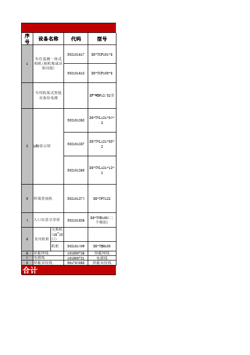
DS-TVL121-08-2
302101263
DS-TVL121-12-2
3
终端查询机
302101274
DS-TPT122
4
入口信息引导屏
302101526 DS-TVB100(二个模组)
交换机(16~18口) 5 6 7 8 室内机柜 机柜 302101409 101500726 101500721 301704053 DS-TBH100 屏蔽网线 电源线 屏蔽双绞线
芜湖大楼车位引导及反向寻
序 号 设备名称 代码
302101617 1 车位监测一体式 相机(相机集成识 别功能) 302101618 DS-TCP103-S
型号
DS-TCP101-S
专用机架式智能 双备份电源
SF-WBP12/32Ⅱ
302101262
DS-TVL121-04-2
2
LED显示屏
302101257
屏蔽芜湖大楼车位引导及反向寻车系统
详细参数 品牌
海康威视
单位
台
海康威视 2U机架式,带32个DC12V输出端口,总输出电流37.5A、 总输出功率450W,内置遇故障自动切换 的主、备双直流电源模块,每路输出具独立自恢复保护及指示灯。带可靠的防雷接地保护,具 有通风散热功能,带网管功能:网络集中管理软件能实时显示电源的输出电压、总负载电流和 内部温度,有主电源模块故障及各种超限报警、故障修复时间等报警记录,具有历史信息查询 下载功能。 工作电压:AC 220V;最大功耗:35.2W;显示方式:即显、左移、上移、上展开、下展开、动态箭 头六种显示方式;扫描场频:400Hz;扫描方式:1/16扫描A模式;屏体尺寸(含边框):735.5× 250.4×90;显示屏边框:黑色铝合金边框;字符显示:支持GB2312字符集,支持32×32点阵常用 汉字;显示颜色:红绿双色;发光点直径/间距:3.75/4.75;通讯方式:RS485;显示数字:可显示 当行,每行显示4个汉字,每个汉字点阵数:32×32;使用环境:温度-20℃~50℃、湿度<95%。 工作电压:AC 220V;最大功耗:48.4W;显示方式:即显、左移、上移、上展开、下展开、动态箭 头六种显示方式;扫描场频:400Hz;扫描方式:1/16扫描A模式;屏体尺寸(含边框):1342.4× 250.4×90;显示屏边框:黑色铝合金边框;字符显示:支持GB2312字符集,支持32×32点阵常用 汉字;显示颜色:红绿双色;发光点直径/间距:3.75/4.75;通讯方式:RS485;显示数字:可显示 当行,每行显示6个汉字,每个汉字点阵数:32×32;使用环境:温度-20℃~50℃、湿度<95%。 工作电压:AC 220V;最大功耗:77W;显示方式:即显、左移、上移、上展开、下展开、动态箭头 六种显示方式;扫描场频:400Hz;扫描方式:1/16扫描A模式;屏体尺寸(含边框):1703.1× 250.4×90;显示屏边框:黑色铝合金边框;字符显示:支持GB2312字符集,支持32×32点阵常用 汉字;显示颜色:红绿双色;发光点直径/间距:3.75/4.75;通讯方式:RS485;显示数字可显示 当行,每行显示10个汉字,每个汉字点阵数:32×32;使用环境:温度-20℃~50℃、湿度<95% 。 显示屏类型:22”AU液晶显示器;触摸屏:22”五线声波式触摸屏;CPU:Intel core E5700; 主板:Intel GA61H;内存:2GB/4GB DDR3 内存;硬盘:WD 320G SATA 接口硬盘;读卡器: (客户自提供);打印机:EPSON TM532热敏打印机(客户自提供);机柜:豪华金属烤漆机 柜;网口:1个RJ45端口;音频:LINE-out;USB:2个USB2.0端口;RESET:1个RESET端口;散 热系统:正压风扇、无噪音、防尘、循环散热;多媒体音响系统:双声道立体声电子音效,环 绕功效,防磁设计。
Metrix Vibration ST5484E 振动传感器数据手册说明书

ST5484E Seismic Velocity 4-20 mA TransmitterDatasheet2-Pin MIL Connector(Option D=4)The ST5484E is a self-contained seismic velocity transmitter that incorporates a piezoelectric accelerometer, signal integrator, RMS peak detector, and a 4-20 mA signal conditioner into a single package. It can be mounted directly on a machine case or bearing housing without intervening signal conditioning equipment. The amplitude of the integrated acceleration (velocity) signal is con -verted to a proportional 4-20 mA signal compatible with industrial process control instrumentation such as PLCs, DCSs, and SCADA systems that can provide trending and/or alarming capabilities for a simplified vibration monitoring strategy.When the flying lead or terminal block connector options are chosen, the transmitter does not need a separate environmental housing and can directly accept conduit. To reduce installed cost, it can be used with barriers for intrinsically safe installations, or wired directly to explosion-proof conduit fittings for explosion- proof installations.Need A Local Display?When continuous, local indication of vibra -tion levels is required at the transmitter, the Metrix ST5491E provides these capabilities.Its sensing and transmitter elements are similar to the ST5484E, but it includes a convenient 2½ digit LCD display in an integral conduit elbow and is rated for use in temperatures from -10o C to +70o C. Refer to Metrix datasheet 1004598 for ordering information and de -tailed specifications.A vibration transmitter may be appropriate in applications where a stand-alone monitoring system may not be warranted.The ST5484E handles general-purpose vibration measurements on a wide range of rotating and reciprocating machinery with ro -tative speeds between 120- and 6,000-rpm. Seismic measure -ments are suitable for machines with rolling-element bearings because shaft vibration in such machines is usually transmitted directly through the bearing to the bearing housing without sub -stantial damping or attenuation. Seismic transducers can also measure vibration that does not originate at the shaft, such as bearing-related wear and defects, footing/foundation problems, piping resonances that are coupled to the machine, etc.Why Measure Velocity?Acceleration and displacement levels are heavily influenced by the frequencies at which the vibration is occurring, while velocity levels are much less influenced. Thus, although acceleration,velocity, and displacement measurements are inter-related math -ematically, seismic velocity measurements tend to be more con -sistent over a wide range of frequencies than either displacement or acceleration. Consequently, broadband (sometimes called “overall” or “unfiltered”) velocity measurements are appropriate for monitoring many machines as a reliable indicator of damag -ing vibratory energy, with the notable exception of machines with fluid-film bearings, which are usually better addressed by shaft-observing proximity probes.Casing displacement is not a practical measurement to make directly and is typically just an integrated seismic velocity mea -surement. As such, the primary decision when selecting a seis -mic sensor will usually be whether to measure casing velocity or casing acceleration. As noted above, casing velocity will often be more appropriate because it tends to be a more reliable indicator of damaging vibratory energy over a broad frequency spectrum for low- to medium-speed machinery.Flying Leads(Option D=0, 1, 5, or 6) (2-wire shown; 4-wire also available)2-Pin Terminal Block(Option D=2)4-Pin Terminal Block(Option D=3)1180OVERVIEWAPPLICATIONSNote: Units sold with an explosion proof rating will in -clude a conduit elbow:8200-000 IEC for ATEX/IECEx/INMETRO/KOSHA/EAC8200-000 for CSAExplosion Proof Versionswith Option D≠4ST5484E Seismic Velocity 4-20 mA TransmitterDatasheetNOTE: For machines with fluid-film bearings, shaft- observing proximity probes will provide more effective vibration measurements than seismic transducers due to the rotor dynamics of the machine and the attenuation of vibratory energy through a fluid-film boundary. Accord -ingly, Metrix recommends and provides proximity probes and associated 4-20 mA transmitters or monitoring systems for such applications.For machines with rolling element bearings and running above 6,000 rpm, and/or where impulsive casing vibration occurs, acceleration may be a better measurement. In such situations, it is recommended that you consult witha Metrix sales professional who can review your application and assist with selection of the proper transducer type and associated transmitter or monitoring system.• RFI/EMI Immunity – Enhanced circuit design and installa -tion techniques aggressively filter out noise from common sources such as handheld radios•Excellent Moisture Resistance – The 2-pin MIL connec -tor version is hermetically sealed to provide an IP67-rated enclosure. Flying lead and terminal block versions are fully potted and rated to IP66 when installed with optional IEC conduit elbow• Hazardous Area Approvals – North American (CSA), Brazil -ian (INMETRO), and European (ATEX & IEC) approvals avail -able•Dynamic Signal Availability – 2-wire versions provide a 4-20 mA velocity- proportional signal for easy connection to PLCs, DCSs, and other plant control systems. Optional 4-wire ver -sions 1 also provide the raw acceleration signal (100 mV/g) for use with vibration data collectors and analyzers • Variety of Connection Options – Flying leads, terminal block, and MIL-type connectors available• Conduit-Ready 2 – Terminal block and flying lead options have conduit threads on top of sensor. No special housings are required for connection of conduit•Rugged, Industrial Design – Robust construction offers out -standing durability; built-in base and housing strain protec -tion helps ensure that over-torqueing sensor-to- machine and sensor-to-conduit connections won’t damage internals or body•High- and Low-Pass Filter Options – The ST5484E can be ordered with a wide variety of low- and high-pass filter options to precisely tailor the band over which vibration is measured•Polarity-Independent Wiring – Metrix patented IPT® tech -nology allows loop power to be connected without regard to voltage polarity, reducing field wiring errors and ensuring that the raw acceleration output 1 is not phase inverted • Multiple Mounting Options – Integral and removablemounting stud options available in both metric and English thread sizes; flat base mounting adapters are also available • Loop-Powered – Runs on nominal 24 V DC power supplied by the 4-20 mA current loop•Wide Supply Voltage Range – Accepts loop power voltages from 11 to 29.6 V DC (intrinsically safe) or 30.0 V DC (explosion proof & non-incendive)• RMS Amplitude Detection – Measures Root Mean Square (RMS) vibration amplitude. Options available for True RMS or scaled RMS (RMS x √2) for “derived peak”•Numerous Full Scale Ranges – The full scale ranges provid -ed in option AAA reflect frequently-ordered ranges; how -ever, many others (too numerous to list) are also available. Consult factory for applications requiring other full scale rangesNotes:1. Dynamic raw acceleration signal available with 4-wire versions only(ordering options D= 1 and D=3).2. Metrix recommends flexible (rather than solid) conduit when pos -sible. Solid conduit can introduce preload forces on the sensor andalter of the vibration response of the sensor.All specifications are at +25°C (+77°F) and +24 V DC supply voltage unless otherwise noted.FEATURESSPECIFICATIONSST5484E Seismic Velocity 4-20 mA TransmitterDatasheetST5484E Seismic Velocity 4-20 mA TransmitterDatasheetA A AB BCD -ST5484E- - -FE ORDERING INFORMATIONST5484E Seismic Velocity 4-20 mA TransmitterDatasheetNOTES:1. Smaller-diameter mounting studs are not able to withstand sus -tained ambient vibration levels above2.0 in/sec. Consult Table 2 for allowable combinations of A and B options.2. The ST5484E uses an RMS amplitude detection circuit. Full scaleranges in peak units use scaled RMS (i.e., RMS x √2). The “derived peak” measurements will equal true peak only under the special case of a pure sinusoid, not complex vibration signals.3. Hazardous Area Certifications are not compatible with all connec -tion types. Consult Table 3 for allowable combinations of C & D options.4. Some approvals require intrinsic safety barriers, others requireExplosion-Proof wiring practices. Refer to Table 4.5. Refer to the Accessories section of this document. Units sold withan explosion proof rating will include an 8200-000 IEC or 8200-000 explosion proof elbow that will be affixed at the factory.6. High- and Low-Pass filter corners for standard filters must beseparated by at least one octave (low-pass frequency must be at least twice the high-pass frequency). All combinations are allowed except E = 6 and F = 4, 5, or 6. Custom filters with closer separa -tion and/or different roll-offs may be available in some instances.Consult the factory if custom filters are required.Conduit elbows are used with flying leads and terminal block versions of the ST5484E transmitter. They are not compatible with MIL-connector versions of the transmitter. A variety of available configurations accommodate English and metric conduit thread sizes, hazardous area approvals, materials of construction, and IP ratings. Note that not all configurations are available with hazardous area approvals or IP ratings. Consult the ordering information below. For ST5484E’s that need an explosion proof (Ex d) rating, that are utiliz -ing flying leads, Option D=0, 1, 5, & 6, will have an attached 8200 conduit elbow and must be used with a certified junction box or other certified connection location. For ST5484E’s that need an explosion proof (Ex d) rating, utilizing integral terminal block, Option D=2 & 3, no junction box is necessary. Table 4 in the datasheet relates what hazardous area (Option C) is allowed per ST5484E Connection (Op -tion D). ST5484E sold with an explosion proof rating (Ex d) will include a 8200 explosion proof elbow and will be affixed at the factory.Copper-free aluminum elbows (all models except AAA=005)Elbow made from 6061-T6 aluminium which is considered a marine grade aluminium and powder coated in epoxy.Stainless steel elbows (models AAA=005)A A A -B 8200- NOTES:1. CSA approved through manufacturer (not Metrix) for the following areas:Class I, Div. 1 (Grps C & D) Class II, Div. 1 (Grps E, F & G) Class III2. B=IEC is only available for AAA=001, 003, and 008 at this time3. ATEX approved through manufacturer (not Metrix), (B=IEC)ITS09ATEX16417UEx II2G, Ex d IIC CML 16ATEX1325X Ex II2GD, Ex db IIB Gb, Ex tb IIIC Db IP65 minimum 4. IECEx approved through manufacturer (not Metrix)IECExITS09.0024UEx d IIC IECEx QPS 16.0012X Ex db IIB Gb, Ex tb IIIC IP665. Elbow 8200-AAA-IEC is required for ST5484E installations meetingATEX/IECEx/INMETRO/KOSHA/EAC Ex d (flameproof) hazardous area certificationsUL approved through manufacturer (not Metrix) for the following areas: Class I; Div. 1 (Grps. B, C, D)Class II; Div. 1 (Grps. E, F, G)NOTE: Dielectric grease must be applied on the rubber boot connector to prevent moisture ingression.NOTE: Dielectric grease must be applied on the rubber boot connectorST5484E Seismic Velocity 4-20 mA TransmitterDatasheet7084-001Flange Mount AdapterAdapts ½” NPT mounting stud on ST5484E to 3-hole flat-base pattern. Hole pattern is three equally spaced 0.26” diameter holes on 1.5” diameter circle. Adapter is 2” diameter x 0.75” thick. Material: 303 stainless steel 7084-002Flange Mount AdapterSame as 7084-001 except center hole adapts ¼” NPT stud on the 5484E.7084-005Flange Mount AdapterSame as 7084-001 except center hole adapts ⅜ x 24 UNF stud on the 5484E.8253-002½” NPT to ¼” NPT Reducer BushingAdapts ¼” NPT stud on ST5484E (B=0) to ½” NPT mounting hole.Material: 303 stainless steel93818-004Cable Grip Strain Relief FittingUsed primarily with 8978 cable assemblies where cable enters junction box. ¾” NPT male thread to cable grip. Fits cable diameters from 0.156” to 0.25”. Complete with sealing ring and locknut. Hot dip / mechanically galvanized fin -ish. Suitable for NEMA 4 junction boxes.93818-018Cable Grip Strain Relief FittingSimilar to 93818-004, but fits larger cable diameters from 0.4”to 0.5”, such as customer-supplied cables used with terminal block versions of ST5484E (D = 2 or 3).OUTLINE DIAGRAMSFigure 1: Outline dimensions of the ST5484E (all versions except MIL-Style Connector). Dimensions in mm [inches]. Optional* 8200-001 conduit elbow shown installed.* NOTE: 8200-000-IEC elbow is mandatory for ATEX/IECEx/INMETRO/KOSHA/EAC Ex d (flameproof) approved installations. The 8200-000 elbow is mandatory for CSA Ex d (flameproof) approved installations.Figure 2: Outline dimensions of theST5484E-XXX-XX4-XX (MIL-Style Connec -tor). Dimensions in mm [inches].ST5484E Seismic Velocity 4-20 mA TransmitterDatasheetWIRING CONNECTIONS+ AND – SYMBOLSARE NOT ON LABELFigure 3: Typical installation for a single ST5484E seismic vibration transmitter.Figure 4: Typical installation for multiple ST5484E seismic vibration transmitters.ADDITIONAL DOCUMENTATIONTrademarks used herein are the property of their respective owners.Data and specifications subject to change without notice.© 2014 Metrix Instrument Co., L.P .。
智能化安防系统技术方案及施工方案

目录一、投标产品技术资料表 (3)二、投标货物的主要技术指标、参数及性能的详细说明 (29)2.1海康威视200万像素日夜型枪机DS-2CD2820FWD (29)2.2海康威视球型摄像机DS-2DF8223I系列 (31)2.3海康威视网络硬盘录像机DS-8664N-XT (36)2.4海康威视联网管理软件iVMS-4200 (39)2.5海康威视视频解码器DS-6416HD-T (40)2.6华三核心交换机LS-5560-30S-EI (41)2.7特雅丽46寸拼接屏幕TYL-SDID4709-D (44)三、相关的图纸、图片 (46)四、产品有效检测和鉴定证明复印件 (47)4.1海康威视200万像素日夜型枪机DS-2CD2820FWD (47)4.2海康威视球型摄像机DS-2DF8223I系列 (48)4.3海康威视网络硬盘录像机DS-8664N-XT (49)4.4海康威视联网管理软件iVMS-4200 (50)4.5华三核心交换机LS-5560-30S-EI (51)五、技术方案 (52)5.1项目概况 (52)5.2需求分析 (52)5.3设计目标 (52)5.4设计原则 (53)5.5设计依据 (54)5.6功能实现 (54)5.7系统组成 (57)六、施工方案 (59)6.1项目概况 (59)6.2编制依据 (59)6.3施工进度计划 (60)6.4施工要求 (62)6.5施工设计 (62)6.6施工准备 (62)6.6.1施工管理制度 (62)6.6.2施工技术准备 (63)6.6.3施工前期准备 (63)6.7施工工艺 (64)6.7.1线管线缆敷设 (64)6.7.2系统设备安装 (66)6.7.3监控中心建设 (68)6.7.4室外道路光缆敷设 (70)6.8进度保证措施 (72)6.8.1施工设备的投入 (72)6.8.2施工人员的投入 (72)6.8.3材料进场及设备检验计划 (72)6.9质量保证措施 (73)6.9.1质量保证体系 (73)6.9.2施工质量的控制 (75)6.10安全保证措施 (76)6.10.1安全生产管理机构 (76)6.10.2安全防护措施 (76)6.11施工流程图 (77)6.12系统调试验收 (82)一、投标产品技术资料表分标(有分标时填写)......投标人(盖单位公章):法定代表人或其委托代理人(签字或盖章):二、投标货物的主要技术指标、参数及性能的详细说明2.1海康威视200万像素日夜型枪机DS-2CD2820FWD主要特性:最高分辨率可达1920×1080 @ 30 fps,在该分辨率下可输出实时图像·采用ROI、SVC等视频压缩技术,压缩比高,且处理非常灵活,超低码率·码流平滑设置,适应不同场景下对图像质量、流畅性的不同要求·支持GBK字库,支持更多汉字及生僻字叠加·支持OSD颜色自选·支持Micro SD/SDHC/SDXC卡(128G)本地存储·ICR红外滤片式自动切换,实现真正的日夜监控·支持日夜两套参数独立配置·支持PoE供电功能·支持3D数字降噪,支持120dB超宽动态·支持双码流,支持手机监控·支持走廊模式,背光补偿,自动电子快门功能,适应不同监控环境·功能齐全:心跳,镜像,一键恢复等·支持智能报警:越界侦测,区域入侵侦测·支持智能后检索,配合NVR支持事件的二次检索分析·支持GB28181接入,支持EHOME平台接入,支持EZVIZ平台接入·支持NAS、Email、FTP、NTP服务器测试·支持HTTPS,SSH等安全认证,支持创建证书·支持用户登录锁定机制,及密码复杂度提示应用场景:适用于金融、电信、政府、学校、机场、工厂、酒店、博物馆、交通监控等要求高清画质且光线较暗的场所,适合逆光环境2.2海康威视球型摄像机DS-2DF8223I系列Smart功能:•Smart跟踪:支持手动跟踪、全景跟踪、事件跟踪等多种跟踪方式并支持多场景巡航跟踪功能•Smart侦测:支持人脸侦测、区域入侵侦测、越界侦测、进入区域侦测、离开区域侦测、徘徊侦测、人员聚集侦测、快速移动侦测、停车侦测、物品遗留侦测、物品拿取侦测、音频异常侦测、移动侦测、视频遮挡侦测功能•Smart道路监控:支持车牌捕获及检索、混行检测、多场景巡航检测、云存储服务功能•Smart录像:支持断网续传功能保证录像不丢失,配合Smart NVR实现事件录像的二次智能检索、分析和浓缩播放•Smart图像增强:支持透雾、强光抑制、电子防抖、Smart IR防红外过曝技术•Smart编码:支持低码率、ROI感兴趣区域增强编码、SVC自适应编码技术•Smart报警:支持网线断、IP地址冲突、存储器满、存储器错、非法访问异常检测并联动报警的功能红外功能:•最低照度0Lux•采用高效红外阵列,低功耗,照射距离达200m•红外灯与倍率距离匹配算法,根据倍率及距离调节红外灯亮度和角度,使图像达到理想的状态•内置热处理装置,降低球机内腔温度,防止球机内罩起雾•恒流电路设计,红外灯寿命达3万小时系统功能:•采用1/1.9”英寸高性能传感器,图像清晰,最大分辨率可达1920x1080•精密电机驱动,反应灵敏,运转平稳,精度偏差少于0.1度,在任何速度下图像无抖动•支持标准的API开发接口,支持海康SDK、ONVIF、CGI、PSIA、GB/T28181和E家协议接入•支持PAL/NTSC制式切换,具有良好的地区适用性•支持RS-485控制下对HIKVISION、Pelco-P/D协议的自动识别•支持三维智能定位功能,配合DVR/客户端软件/IE可实现点击跟踪和放大•支持系统双备份功能,确保数据断电不丢失•支持断电状态记忆功能,上电后自动回到断电前的云台和镜头状态•防雷、防浪涌、防突波,IP66防护等级•支持定时任务预置点/花样扫描/巡航扫描/自动扫描/垂直扫描/随机扫描/帧扫描/全景扫描/球机重启/球机校验/辅助输出等功能机芯功能:•23倍光学变倍,16倍数字变倍•支持自动光圈、自动聚焦、自动白平衡、背光补偿、宽动态、3D数字降噪•支持区域曝光、区域聚焦功能•支持星光级超低照度,0.005Lux/F1.5(彩色),0.0005Lux/F1.5(黑白) ,0 Lux with IR•支持多边形隐私遮蔽,多区域可设,多颜色、马赛克可选网络功能:•采用高性能平台,性能可靠稳定•支持以太网控制,同时支持模拟输出•可通过IE浏览器和客户端软件观看图像并实现控制•支持标准的Micro SD/SDHC/SDXC卡存储•支持NAS存储录像,录像可断网续传,最高可支持8个NAS盘•支持三级用户权限管理,支持授权的用户和密码,支持HTTPS加密和IEEE 802.1x网络访问控制、IP地址过滤•支持三码流技术•支持H.264/MJPEG/MPEG4视频压缩算法,支持多级别视频质量配置、H.264编码复杂度Baseline/Main/High Profile,支持实时视频输出分辨率为HDTV1080p(符合SMPTE274M标准)、960p和HDTV720p(符合SMPTE296M标准)•支持多种网络协议,IPv4/IPv6,HTTP,HTTPS,802.1x, Qos,FTP,SMTP,UPnP,SNMP,DNS,DDNS,NTP,RTSP,RTCP,RTP,TCP,UDP,IGMP,ICMP,DHCP,PPPoE,Bonjour•支持1路音频输入和1路音频输出云台功能:•水平方向360°连续旋转,垂直方向-15°-90°,无监视盲区•水平预置点速度最高可达240°/s,垂直预置点速度最高可达200°/s•水平键控速度为0.1°-160°/s,垂直键控速度为0.1°-120°/s•支持300个预置位,并具有预置点视频冻结功能•支持8条巡航扫描,每条可添加32个预置点•支持4条花样扫描,每条路径记录时间大于10分钟•支持比例变倍功能,旋转速度可以根据镜头变倍倍数自动调整•支持守望功能,预置点/花样扫描/巡航扫描/自动扫描/垂直扫描/随机扫描/帧扫描/全景扫描可在空闲状态停留指定时间后自动调用(包括上电后进入的空闲状态)•支持报警功能,内置7路报警输入和2路报警输出,支持报警联动,可在报警后触发调用预置点/巡航扫描/花样扫描/SD卡录像/触发开关量输出/客户端电子地图/智能抓图/上传FTP/邮件联动2.3海康威视网络硬盘录像机DS-8664N-XT功能特性:•独特的机箱专利设计,设备运行低噪环保;前置插槽式的硬盘安装方式,安装维护更加便捷;•可接驳符合ONVIF、PSIA、RTSP标准及众多主流厂商(ARECONT、AXIS、Bosch、Brickcom、Canon、HUNT、Panasonic、PELCO、SAMSUNG、SANYO、SONY、VIVOTEK、ZAVIO)的网络摄像机;•支持600W像素高清网络视频的预览、存储与回放;• 支持IPC集中管理,包括IPC参数配置、信息的导入/导出、语音对讲和升级等功能;•支持HDMI、VGA、CVBS同时输出,HDMI与VGA输出分辨率最高均可达1920x1080p,且可分别预览或回放不同通道的图像;• 全新的UI操作界面,支持一键开启录像功能;•图像预览与回放时,支持音量大小调节;• 支持预览与回放界面实时抓图功能;• 支持冗余录像、假日录像和抓图计划配置;• 支持ANR技术,实现网络摄像机断网智能补录功能;•支持海康SMART IPC场景变更侦测,区域入侵侦测,音频异常侦测,虚焦侦测,移动侦测,人脸侦测等多种智能侦测接入与联动,支持智能搜索、回放及备份功能,有效提高录像检索与回放效率;• 支持即时回放功能,在预览画面下对指定通道的当前录像进行回放,并且不影响其他通道预览;•支持最大16路720p同步回放及多路同步倒放;•支持标签定义、查询、回放录像文件;•支持重要录像文件加锁保护功能;• 支持硬盘配额和硬盘盘组两种存储模式,可对不同通道分配不同的录像保存容量或周期;•支持16个SATA接口,2个eSATA盘库,可用于录像和备份;•支持N+1热备功能,一台工作NVR异常下线时,热备NVR接管异常NVR工作,提升数字通道存储的可靠性;•双千兆网卡,支持网络容错、负载均衡以及双网络IP设定等应用;•支持海康威视DDNS域名解析系统;•支持远程转码预览和转码回放功能,可对编码后的图像分辨率、码率、帧率等进行转换,为远程监控提供更多的选择方案;•支持远程零通道预览,使用1路零通道编码视频,预览多通道分割的视频画面,充分获取监控图像信息的同时节省网络传输带宽;•支持网络检测(网络流量监控、网络抓包、网络通畅)功能;2.4海康威视联网管理软件iVMS-4200功能特性:•支持局域网和公网两种应用环境。
RMR5030MM58EE8F-1600

,( ( 4" .!-!.!%&!, <! &. ""4%5 - (%, 8 < ,4.!& 4 %" - &. ""4%59#
& 4=( !" <!
"45%(* A<!% <45< (%, ,!(& 4=( !" <! "45%(* A<!% * A# 7
,!(& 4=( 4%5 <! &* &1"
ECC: 0: Without ECC 1: With ECC
Speed: 800˖PC3-6400 1066: PC3-8500 1333:PC3-10600 1600˖PC3-12800 1866˖PC3-14900
DRAM Package: F: FBGA W: WBGA
DRAM Vendor: M: Micron H: Hynix S: Infineon L: Longmax E: Elpida K: Samsung
#
(%,
+ '"!, - . ,/(*0.(%1 ' 2 "3 % /"!, % "4%5*!0.(%1 ' 2
#
/"!, )7 6!6 .7 )/" (%(*7"4" *" 8/%/"!, % 6!6 .7 2 "9
# ,,.!"" :4%" ; (%, (%, &(% )! 64.. .!, . % 64.. .!,#
Ver2.0/Apr.09
DrayTek VigorAP 960C 802.11ax Ceiling-mount Access

VigorAP 960C802.11ax Ceiling-mount AccessPointQuick Start GuideVersion: 1.2Firmware Version: V1.4.5(For future update, please visit DrayTek web site)Date: Dec. 21, 2022Intellectual Property Rights (IPR) InformationCopyrights © All rights reserved. This publication contains information that is protected by copyright. No part may be reproduced, transmitted, transcribed, stored ina retrieval system, or translated into any language without written permissionfrom the copyright holders.Trademarks The following trademarks are used in this document:●Microsoft is a registered trademark of Microsoft Corp.●Windows, Windows 8, 10, 11 and Explorer are trademarks of MicrosoftCorp.●Apple and Mac OS are registered trademarks of Apple Inc.●Other products may be trademarks or registered trademarks of theirrespective manufacturers.Safety Instructions and ApprovalSafety Instructions ●Read the installation guide thoroughly before you set up the device.●The device is a complicated electronic unit that may be repaired only beauthorized and qualified personnel. Do not try to open or repair thedevice yourself.●Do not place the device in a damp or humid place, e.g. a bathroom.●Do not stack the devices.●The device should be used in a sheltered area, within a temperaturerange of 0 to +40 Celsius.●Do not expose the device to direct sunlight or other heat sources. Thehousing and electronic components may be damaged by direct sunlight or heat sources.●Do not deploy the cable for LAN connection outdoor to preventelectronic shock hazards.●Keep the package out of reach of children.●When you want to dispose of the device, please follow local regulationson conservation of the environment.Warranty We warrant to the original end user (purchaser) that the device will be free from any defects in workmanship or materials for a period of two (2) yearsfrom the date of purchase from the dealer. Please keep your purchase receiptin a safe place as it serves as proof of date of purchase. During the warrantyperiod, and upon proof of purchase, should the product have indications offailure due to faulty workmanship and/or materials, we will, at our discretion,repair or replace the defective products or components, without charge foreither parts or labor, to whatever extent we deem necessary tore-store theproduct to proper operating condition. Any replacement will consist of a newor re-manufactured functionally equivalent product of equal value, and willbe offered solely at our discretion. This warranty will not apply if the productis modified, misused, tampered with, damaged by an act of God, or subjectedto abnormal working conditions. The warranty does not cover the bundled orlicensed software of other vendors. Defects which do not significantly affectthe usability of the product will not be covered by the warranty. We reservethe right to revise the manual and online documentation and to make changesfrom time to time in the contents hereof without obligation to notify anyperson of such revision or changes.Declaration of ConformityHereby, DrayTek Corporation declares that the radio equipment type VigorAP 960C is in compliance with Directive 2014/53/EU.The full text of the EU declaration of conformity is available at the following internet address: https:///VigorAP 960C/Document/CE/Manufacturer: DrayTek Corp.Address: No.26, Fushing Rd., Hukou, Hsinchu Industrial Park, Hsinchu 303, Taiwan Product: VigorAP 960CFrequency Information for Europe area:2.4GHz WLAN 2400MHz - 2483MHz, max. TX power: 19.95dBm5GHz WLAN 5150MHz - 5350MHz, max. TX power: 22.84dBm5470MHz - 5725MHz, max. TX power: 28.14dBmRequirements in AT/BE/BG/CZ/DZ/DK/EE/FR/DE/IS/IE/IT/EL/ES/CY/LV/LI/LT/ LU/HU/MT/NL/NO/PL/PT/RO/SI/SK/TR/FI/SE/CH/HR.5150MHz~5350MHz is for indoor use only.This product is designed for 2.4GHz and 5GHz WLAN network throughout the EC region.Declaration of ConformityHereby, DrayTek Corporation declares that the radio equipment type VigorAP 960C is in compliance with Regulation SI 2017 No. 1206.Manufacturer: DrayTek Corp.Address: No.26, Fushing Rd., Hukou, Hsinchu Industrial Park, Hsinchu 303, Taiwan Product: VigorAP 960CImporter: CMS Distribution Ltd: Bohola Road, Kiltimagh, Co Mayo, IrelandFrequency Information for UK area:2.4GHz WLAN 2400MHz - 2483MHz, max. TX power: 19.95dBm5GHz WLAN 5150MHz - 5350MHz, max. TX power: 22.84dBm5470MHz - 5725MHz, max. TX power: 28.14dBmRequirements in UK. 5150MHz~5350MHz is for indoor use only.This product is designed 2.4GHz and 5GHz WLAN network use in the UK & Ireland.Regulatory InformationFederal Communication Commission Interference StatementThis equipment has been tested and found to comply with the limits for a Class B digital device, pursuant to Part 15 of the FCC Rules. These limits are designed to provide reasonable protection against harmful interference in a residential installation. This equipment generates, uses and can radiate radio frequency energy and, if not installed and used in accordance with the instructions, may cause harmful interference to radio communications. However, there is no guarantee that interference will not occur in a particular installation. If this equipment does cause harmfulinterference to radio or television reception, which can be determined by turning the equipment off and on, the user is encouraged to try to correct the interference by one of the following measures:● Reorient or relocate the receiving antenna.● Increase the separation between the equipment and receiver.● Connect the equipment into an outlet on a circuit different from that to which the receiver is connected.●Consult the dealer or an experienced radio/TV technician for help.This device complies with Part 15 of the FCC Rules. Operation is subject to the following two conditions:(1) This device may not cause harmful interference, and(2) This device may accept any interference received, including interference that may cause undesired operation.Company nameABP International Inc.Address 13988 Diplomat Drive Suite 180 Dallas TX 75234 ZIP Code 75234E-mail*******************USA Local Representative Contact PersonMr. Robert MesserTel. 19728311600Caution ● Any changes or modifications not expressly approved by the grantee of this device could void the user's authority to operate the equipment.● Any changes or modifications not expressly approved by the party responsible for compliance could void the user's authority to operate this equipment.● This transmitter must not be co-located or operating in conjunction with any other antenna or transmitter.●Radiation Exposure Statement: This equipment complies with FCC radiation exposure limits set forth for an uncontrolled environment. This equipment should be installed and operated with minimum distance 20cm between the radiator & your body.External Power Supply ErP Information1 2A Manufacturer DVE DVEB Address No.5, Baogao Rd, XindianDist, New Taipei City(23144), TaiwanNo.5, Baogao Rd, XindianDist, New Taipei City(23144), Taiwan DSA-12PF09-12 FUK DSA-18PFR-12 FUKC Model identifierDSA-12PF09-12 FEU DSA-18PFR-12 FEU D Input voltage 100~240V 100~240VInput AC frequency 50/60Hz 50/60HzEOutput voltage DC 12.0V 12.0VF Output current 1.0A 1.5AG Output power 12.0W 18.0WH Average active efficiency 83.3% 85.5%I Efficiency at low load 10% 80.8% 83.7%J No-load power consumption 0.06W 0.07W*The external power supply used for each product will be model dependent.For more update, please visit .T a b l e o f C o n t e n t s1. Package Content (1)2. Panel Explanation (2)3. Installation (3)3.1 Ceiling-mount Installation (Wooden Ceiling) (3)3.2 Ceiling-mount Installation (Plasterboard Ceiling) (4)3.3 Suspended Ceiling (Lightweight Steel Frame) Installation (5)3.4 Wall-Mounted Installation (7)4. Connection and Configuration (8)4.1 Notifications for Hardware Connection (8)4.2 Connect to a Vigor Router using AP Management (9)4.3 Web Configurations (10)5. Customer Service (14)Be a Registered Owner (14)Firmware & Tools Updates (14)1.P a c k a g e C o n t e n tTake a look at the package content. If there is anything missed or damaged, please contact DrayTek or dealer immediately.VigorAP 960C Main Unit Ceiling mount bracket & Quick StartGuideT-Rail Mounting Kits(Used for suspended ceiling)Fixings and Screws(for ceiling mounting) RJ-45 Cable (Ethernet)Screw set (for wall mounting) The type of the power adapter depends on the country that the AP will be installed:UK-type Power Adapter EU-type Power AdapterUSA/Taiwan-type Power Adapter AU/NZ-type Power AdapterThe maximum power consumption is 11 Watt.2. P a n e l E x p l a n a t i o nLED Status ExplanationOn The system is in boot-loader mode. OffThe system is not ready or fails.Blue LEDBlinking The system is in AP mode and work normally.Green LED BlinkingThe system is in Mesh mode or Range Extender modeand works normally.Orange LED Blinking The system is in TFTP mode. Off Off VigorAP is turned off or not functioning. Interface Explanation Ethernet Port Connects to LAN or router.Supports PoE power & Gigabit (1000BaseT).Power Jack (DC IN) Connecter for a power adapter. Hole Explanation Factory Reset Restores the unit back to factory default settings.To use, insert a small item such as an unbent paperclip into the hole. You will feel the button inside depress gently. Hold it for 5 seconds. The VigorAP will restart with the factory default configuration and the LED will blink blue.Note● For the sake of security, make the accessory kit away fromchildren.● Remove the protective film from the access point before useto ensure ventilation.LEDFactory ResetEthernet PortPower Jack (DC IN)3. I n s t a l l a t i o nVigorAP can be installed under certain locations: wooden ceiling, plasterboard ceilings, light-weighted steel frame and wall.3.1 C e i l i n g -m o u n t I n s t a l l a t i o n (W o o d e n C e i l i n g )1. Place the bracket under the wooden ceiling and fasten two screws firmly (asshown in Figure below, Step 1). 2. When the bracket is in place, fasten two screws firmly (as shown in Figurebelow, Step 2) on the bottom of VigorAP. 3. Make the device just below the bracket. Put the screws installed in Step 2 onthe holes of the bracket (as shown in Figure below, Step 3). 4. Gently rotate the device to make screws slide into the notches of thebracket and move forward till it is firmly fixed.Step 1Step 2BracketStep 33.2 C e i l i n g -m o u n t I n s t a l l a t i o n (P l a s t e r b o a r d C e i l i n g )1. Place the bracket under the plasterboard ceiling and fasten two turnbuckles firmly (as shown in Figure below, Step 1).2. Make the screws pass through the bracket and insert into the turnbuckles (asshown in Figure below, Step 2). Fasten them to offer more powerful supporting force.3. When the bracket is in place, fasten two screws firmly (as shown in Figurebelow, Step 3) on the bottom of VigorAP.4. Make the device just below the bracket. Put the screws installed in Step 3 onthe screw holes of the bracket (as shown in Figure below, Step 4).5. Gently rotate the device to make screws slide into the notches of thebracket and move forward till it is firmly fixed.BracketStep 1Step 2Step 3Step 43.3 S u s p e n d e d C e i l i n g (L i g h t w e i g h t S t e e l F r a m e )I n s t a l l a t i o nYou cannot screw into ceiling tiles as they are weak and not suitable for bearing loads. Your VigorAP is supplied with mounts (T-Rail brackets) which attach directly to the metal grid (‘T-Rail’) of your suspended ceiling.1. Choose one set of T-Rail mounting kits from the bundled package.2. Put the T-Rail brackets on the holes of the bottom side of the device. Fastenthem with suitable screws.3. If a larger gap is required between the ceiling and the VigorAP, use theextension pieces to extend the height of the brackets.T-Rail BracketExtension PieceT-Rail BracketExtension Piece4.Attach the T-Rail brackets to the ceiling frame.NoteWarning: The screw set shown below is for wall mounting only. Do not use such set for ceiling mounting due to the danger offalling.3.4 W a l l -M o u n t e d I n s t a l l a t i o nFor wall-mounting, the VigorAP has keyhole type mounting slots on the underside. You can fit the AP at any axis (i.e. 12, 3, 6 or 9 O’Clock) to allow for cable entry from the most convenient location if you are using side entry – note the position of the side entry cable cutout.1. A template is provided on the VigorAP’s packaging box to enable you tospace the screws correctly on the wall.2. Place the template on the wall and drill the holes according to therecommended instruction.3. Fit screws into the wall using the appropriate type of wall plug (as shown inthe ceiling section) but do not use the ceiling bracket – the VigorAP hangs directly onto the screws.Wall (wooden, concrete, plasterboard or others)4.C o n n e c t i o n a n d C o n f i g u r a t i o n4.1N o t i f i c a t i o n s f o r H a r d w a r e C o n n e c t i o n●If required, remove the protective cap of VigorAP to create extra spacefor the cables to pass through.●Connect VigorAP to Vigor router (via LAN port) with Ethernet cable.●Connect VigorAP to PoE switch (via LAN port) with Ethernet cable. Forconnecting with PoE switch, do not connect the power adapter. VigorAPwill get the power from the switch directly.4.2C o n n e c t t o a V i g o r R o u t e r u s i n g A P M a n a g e m e n tYour VigorAP can be used with Vigor routers which support AP management (such as the Vigor2865 or Vigor2927 series). AP Management enables you to monitor and manage multiple DrayTek APs from a single interface.1.Connect one end of the power adapter to power port of VigorAP, and theother side into a wall outlet.2.Access into the web user interface of Vigor router. Here we take Vigor2865as an example. Open Central Management>>AP>>Status.3.Locate VigorAP 960C. Click the IP address assigned by Vigor router to accessinto web user interface of VigorAP 960C.4.After typing username and password (admin/admin), the main screen will bedisplayed.4.3W e b C o n f i g u r a t i o n sThis section will guide you to install the AP and make configuration for VigorAP.C o n n e c t e d A s a M e s h N o d e(i n M e s h N e t w o r k)❶Install VigorAP on to the ceiling.❷As a mesh node, settings related to VigorAP 960C must be configured by a remote Mesh Root (e.g., VigorAP 903) within the mesh network.The user must detect VigorAP 960C via a Mesh Root to add it as a meshnode.C o n n e c t e d A s a n A c c e s s P o i n tAs an access point, VigorAP 960C must be connected to a router and configured in AP (Access Point) / Range Extender mode.❶Install VigorAP on to the ceiling.❷Use a twisted-pair cable with RJ-45 plugs at both ends, and plug into Ethernet device (e.g., Vigor router) and Ethernet port of VigorAP.❸ There are two methods to configure VigorAP.Method 1:(a) First, open a web browser on your PC and type https://192.168.1.2. Apop-up window will open to ask for username and password.Note You may either simply set up your computer to get IPdynamically from the router or set up the IP address of thecomputer to be in the same subnet as the IP address ofVigorAP 960C.● If there is no DHCP server on the network, then VigorAP960C will have an IP address of 192.168.1.2.● If there is DHCP available on the network, then VigorAP960C will receive its IP address via the DHCP server.● If you connect to VigorAP by wireless LAN, you could tryto access the web user interface through .(b) After clicking Login, Quick Start Wizard for configuring wirelesssettings will appear as follows.(c)Follow the on-screen steps to finish the network connection.Method 2:(a)Use a mobile phone to scan the QR code named with DrayTek WirelessApp to download DrayTek Wireless APP.(b)After downloading, run the APP.(c)From the home page, click the Connect icon to access the Connectpage. Next, press the QR code icon next to Scan QR Code on yourphone screen to open the camera.Scan the QR code named with Connect SSID to access the web user interface (configuration wizard) of VigorAP 960C. (For iOS users, the SSID and the password will be shown first. Simply click the Connect button to access the web user interface of VigorAP.)5.C u s t o m e r S e r v i c eIf the device cannot work correctly after trying many efforts, please contact your dealer/DrayTek for further help right away. For any questions, please feel freetosende-mailto“*******************”.B e a R e g i s t e r e d O w n e rWeb registration is preferred. You can register your Vigor router viahttps://..F i r m w a r e&T o o l s U p d a t e sDue to the continuous evolution of DrayTek technology, all routers will beregularly upgraded. Please consult the DrayTek web site for more information on newest firmware, tools and documents.https://GPL Notice This DrayTek product uses software partially or completely licensedunder the terms of the GNU GENERAL PUBLIC LICENSE. The author ofthe software does not provide any warranty. A Limited Warranty isoffered on DrayTek products. This Limited Warranty does not coverany software applications or programs.To download source codes please visit:GNU GENERAL PUBLIC LICENSE:https:///licenses/gpl-2.0Version 2, June 1991For any question, please feel free to contact DrayTek technical*************************************************.14。
MC9RS08KA4_8中文数据手册
3FFE
3FFF
BC(JMP 机器码)
跳转地址高字节
跳转地址低字节
飞 3.4 激活背景调试模式 背景调试功能是由 RS08 核内的 BDC 管理的。在软件开发过程中,BDC 提供了
H 一种分析 MCU 操作方法。 C 有 4 种激活背景调试的方法:
*在 POR 期间或发出背景调试强制复位命令之后,拉 BKGD/MS 引脚为低
3
北京飞锐泰克科技有限公司 tel:010-59831537 fax:010-59831536
数字化X射线摄影系统产品技术要求深圳蓝韵

2.5.4预览时间
型号
Wiser-01
Wiser-02
Wiser-03
CXDI-401G
COMPACT
CXDI-401G
Wireless
预览时间
≤11s
≤9s
≤12s
≤5s
≤5s
2.6高压电缆及插头、插座
应符合GB/T 10151-2008的规定。
2.7
2.7.1
应整齐、表面整洁、色泽均匀,不得有伤斑、裂缝等缺陷。
见下表:
型号
Wiser -01
Wiser-02
Wiser -03
CXDI-401G
COMPACT
CXDI-401G
Wireless
影像均匀性
≤2.2%
≤2.2%
≤2.2%
≤2.2%
≤2.2%
2.3.4
实际有效成像区域应大于探测器有效成像区域标称值的95%。
型号
Wiser -01
Wiser-02
Wiser -03
5%;
立柱水平运动
手动控制,电磁锁止, 运动行程≥
1400mm
手动控制,电磁锁止,运动行程≥
1500mm
立柱旋转
手动控制,机械锁
止,旋转范围不小于±180°
手动控制,机械锁
止,旋转范围不小于±180°
2.4.2
X射线管组件密封应良好,无渗油现象。
2.4.3
a)限束器启闭应轻便、灵活、可靠;
b)最小X射线辐射野应符合GB9706.12-1997中29.202.4a)的规定,在距焦点1m处垂直于基准轴的平面上,可选择X射线野最小尺寸,其长、宽不超过5cm;
标尺
手动控制,电磁锁止 , 转 动 范 围
英飞拓产品型号

英飞拓产品型号英飞拓产品型号渠道产品,价格优惠,不满意可退货 150********2.1 固定摄像机-PALV5101-A50142 ⼀体化摄像机2.3 因定半球摄像机2.4 V1700A系列快球2.5 V1750A系列充氮快球2.6 V1700S系列内置单模光端机的快球2.7 V1900A系列快球2.8⼀体化云台摄像机2.9恒速球形护罩/云台2.10快球零部件1.模拟监控前端产品2.1 固定摄像机V5101-A2014 V5101-A3014 V5101-A5014 V5101-A2019 V5101-A3019 V5102-A2014 V5102⽇夜型因定摄像机V5102-A3014 V5102-A5014V5102-A3019 V5102-A2019V5103宽动态彩⾊固定摄像机V5103-A3014V1025-1H⾼解析度彩⾊摄像机V1025-1HV1026-1⾼解析度⽇夜转换型摄像机V1026-1V1027-1 1/2英⼨宽动态⾼灵敏度低照度彩⾊摄像机V1027-1V1033-1宽动态⽇夜转换型摄像机V1033-12.2⼀体化摄像机PALV1224⼀体化彩⾊摄像机V1224-22A14V1244⼀体化⽇夜转换摄像机V1244-23A14 V1244-26A14 V5411-A2014ST V5411-A2014SU V5411-A2014SV 2.3固定半球摄像机PALV5411-A2014SW V5411-A2014SX V5411-A2014SYV5411-A2014SZ480线⼿动变焦⾃动光圈镜头V5411-A2014 SBV5411-A2014 SDV5411-A2014SE V5411-A2014SC V5411-A2014SF520线固定焦距镜头V5411-A3014ST V5411-A3014SU V5411-A3014SV V5411-A3014SW V5411-A3014SX V5411-A3014SY V5411-A3014SZ520线⼿动变焦⾃动光圈镜头V5411-A3014SB V5411-A3014SD V5411-A3014SE V5411-A3014SCV5512室内⽇夜型因定半球摄像机V5411-A3014SF V5512-A2014SB V5512-A2014SE520线⼿动变焦⾃动光圈镜头V5512-A3014SB V5512-A3014SEV5413室内宽动态彩⾊固定半球摄像机V5512-A3014SB V5413-A3024SB V5413-A3024SE2.3固定半球摄像机PALV5411-A2014ST V5411-A2014SU V5411-A2014SV V5411-A2014SW V5411-A2014SXV5411-A2014SY480线⼿动变焦⾃动光圈镜头V5411-A2014SZ V5411-A2014SB V5411-A2014SD V5411-A2014SE V5411-A2014SC V5411-A2014SF520线固定焦距镜头V5411-A3014ST V5411-A3014SU V5411-A3014SV V5411-A3014SW V5411-A3014SZ V5411-A3014SY V5411-A3014SX520线⼿动变焦⾃动光圈镜头V5411-A3014SB V5411-A3014SD V5411-A3014SE V5411-A3014SCV5512室内⽇夜型因定半球摄像机V5411-A3014SF V5512-A2014SB520线⼿动变焦⾃动光圈镜头V5512-A2014SE V5512-A3014SB V5512-A3014SB V5512-A3014SEV5413室内宽动态彩⾊固定半球摄像机V5413-A3024SBV1700A系列快球PAL室内吸顶装快球V1725A-C1C2C6 V1726A-C1C2C6 V1727A-C1C2C6 V1728A-C1C2C6 V1724A-C1C2C6 V1729A-C1C2C6 V1723A-C1C2C6室内⽀架装快球V1725A-C1C2B6 V1726A-C1C2B6 V1727A-C1C2B6 V1728A-C1C2B6 V1724A-C1C2B6 V1729A-C1C2B6 V1723A-C1C2B6室外吸顶装快球V1745A-C1C2C6 V1746A-C1C2C6 V1747A-C1C2C6 V1748A-C1C2C6 V1744A-C1C2C6 V1749A-C1C2C6 V1743A-C1C2C6室外⽀架装快球V1745A-C1C2B6 V1746A-C1C2B6 V1747A-C1C2B6 V1748A-C1C2B6 V1744A-C1C2B6 V1749A-C1C2B6 V1743A-C1C2B62.5 V1750A 系列充氮快球-PAL室内充氮吊装快球V1757A-C1C3B6 V1758A-C1C3B6 V1759A-C1C3B6 V1753A-C1C3B6 V1791室内内置单模光端机吸顶装快球V1725S-C1C2C6 V1726S-C1C2C6 V1727S-C1C2C6 V1728S-C1C2C6 V1729S-C1C2C6 V1723S-C1C2C6室内内置单模光端机⽀架装快球V1725S-C1C2B6V1726S-C1C2B6V1727S-C1C2B6 V1728S-C1C2B6 V1729S-C1C2B6 V1723S-C1C2B6室外内置单模光端机吸顶装快球V1745S-C1C2C6 V1746S-C1C2C6 V1747S-C1C2C6 V1748S-C1C2C6 V1743S-C1C2C6 V17243S-C1C2C6室外内置单模光端机⽀架装快球V1745S-C1C2B6 V1746S-C1C2B6 V1747S-C1C2B6 V1748S-C1C2B6 V1749S-C1C2B6 V1724S-C1C2B62.7V1900A系列快球PAL室内吸顶装快球V1901A-C1C2C6 V1902A-C1C2C6 V1903A-C1C2C6 V1904A-C1C2C6 V1906A-C1C2C6室内⽀架装快球V1901A-C1C2B6 V1902A-C1C2B6 V1903A-C1C2B6 V1904A-C1C2B6 V1906A-C1C2B6室外吸顶装快球V1911A-C1C2C6 V1912A-C1C2C6 V1913A-C1C2C6 V1914A-C1C2C6 V1916A-C1C2B6 V1917A-C1C2B6室外⽀架装快球V1911A-C1C2B6 V1912A-C1C2B6 V1913A-C1C2B6 V1914A-C1C2B6 V1916A-C1C2B6 V1917A-C1C2B62.8 ⼀体化云台摄像机V1492-18A15 V1492-23A15 V1492-26A15 V1492-35A15 V1492-36A15 V1492-18A16 V1492-23A16 V1492-26A16 V1492-35A16 V1492-36A16 V1492-18A17 V1492-23A17 V1492-26A17 V1492-35A17 V1492-36A17 V1492-18A18 V1492-23A18 V1492-26A18 V1492-35A18V1492-36A18⼀体化云台⽀架(适⽤于V1492、V1493)V1662-W1 V1662-S1 V1662-C1 V1662-DV1493中型⾼速云台V1493-D16V7A15 V1493-DP16V7A15 V1493-A15 V1493-D16V7A16 V1493-DP16V7A16 V1493-A16 V1493-D16V7A17 V1493-DP16V7A17 V1493-A17 V1493-D16V7A18 V1493-DP16V7A18 V1493-A18V1631隔爆云台摄像机V1631-23A19 V1631-25A19防爆护罩V1421-15SHB6-2V1421-15SHB8-2V1421-15A6-2V1421-15A8-2隔爆云台⽀架V1664-W V1664-C V1664-S V1665-W12.9恒速球形护罩/云台V1682 系列室内/室外恒速球形云台V1682-C2B-9HBPV1682-C2B-9HBP2.10 快球零部件V1761 V1761L V1762 V1763 V1764 V1764A V1764B V1765 V1765A V1766适⽤V1750A系列充氮快球V1761S V1762S V1763S球芯V1700N系列⽹络快球球芯(PAL)(坜另配视频缟码卡)V1825N-C16 V1826N-C16 V1827N-C16 V1828N-C16 V1829N-C16 V1825N-C15 V1826N-C15 V1827N-C15V1828N-C16 V1829N-C16V1700A系列快球球芯(PAL)V1825A-C16 V1826A-C16 V1827A-C16 V1828A-C16 V1829A-C16 V1825N-C15 V1826N-C15 V1827N-C15V1828N-C16 V1829N-C16V1750A系列充氮快球球芯(PAL)V1825AP-C16 V1826AP-C16 V1827AP-C16 V1828AP-C16 V1829AP-C16 V1825AP-C15 V1826AP-C15 V1827AP-C15 V1828AP-C15 V1829AP-C15V1700S系列光端机快球球芯(PAL)V1825AF-C16 V1826 AF-C16 V1827 AF-C16 V1828 AF-C16 V1829 AF-C16 V1825AF-C15 V1826 AF-C15 V1827 AF-C15 V1828 AF-C15 V1829 AF-C15V1900A系列快球球芯(PAL)V1901A-C16 V1902A-C16 V1903A-C16 V1904A-C16 V1905A-C16 球罩快球下罩(不带法兰)V1840-C2 V1840-S2 V1840-C3 V1840-S3室内吸顶装配罩下罩(带法兰)V1840-C2C V1840-S2C V1840-C3C V1840-S3C室内⽀架装配罩下罩(带法兰)V1840-C2B V1840-S2B V1840-C3B V1840-S3B室外⽀架装和吸顶装配罩下罩(带法兰和加热器)V1840-C2O V1840-S2O V1840-C3O V1840-S3O V1840P-C3OV1840P-S3O快球上罩(带法兰)V1850-IC V1850-IB V1850-OC V1850-OB V1850P-OB V1852-IC V1852-IB V1852-OC V1852-OB快球电源板V1860A-C6 V1860N-L6 V1860A-C5 V1860N-L5快球电源V3922-24A-26.键盘及辅助设备6.1 键盘V2100 V2109X V2111X V2110 V2115 V2116X7.3 V2020系列中型矩阵切换/控制器V2020AX-16X4 V2020AX-16X8 V2020AX-16X12 -16X16 V2020AX-16X20 V2020AX-16X24 V2020AX-16X28V2020AX-16X32 V2020AX-32X4 V2020AX-32X8 V2020AX-32X12 V2020AX-32X16 V2020AX-32X20 V2020AX-32X24 V2020AX-32X28 V2020AX-32X32 V2020AX-48X4 V2020AX-48X8V2020AX-48X12 V2020AX-48X16 V2020AX-48X20 V2020AX-48X24 V2020AX-48X28 V2020AX-48X32 V2020AX-64X4 V2020AX-64X8 V2020AX-64X12 V2020AX-64X16 V2020AX-64X20 V2020AX-64X24 V2020AX-64X28 V2020AX-64X32 V2020AX-80X4 V2020AX-80X8 V2020AX-80X12 V2020AX-80X16 V2020AX-80X20 V2020AX-80X24V2020AX-80X28 V2020AX-80X32 V2020AX-96X4 V2020AX-96X8 V2020AX-96X12 V2020AX-96X16 V2020AX-96X20 V2020AX-96X24 V2020AX-96X28 V2020AX-96X32V2020AX-112X4 V2020AX-112X8 V2020AX-112X12 V2020AX-112X16 V2020AX-112X20 V2020AX-112X24V2020AX-112X28 V2020AX-112X32 V2020AX-128X4 V2020AX-128X8 V2020AX-128X12 V2020AX-128X16V2020AX-128X20 V2020AX-128X24 V2020AX-128X28 V2020AX-128X32 V2020AX-144X4 V2020AX-144X8V2020AX-144X12 V2020AX-144X16 V2020AX-144X20 V2020AX-144X24 V2020AX-144X28 V2020AX-144X32V2020AX-160X4 V2020AX-160X8 V2020AX-160X12 V2020AX-160X16 V2020AX-160X20 V2020AX-160X24V2020AX-160X28 V2020AX-160X32 V2020AX-176X4 V2020AX-176X8 V2020AX-176X12 V2020AX-176X16V2020AX-176X20 V2020AX-176X24 V2020AX-176X28 V2020AX-176X32 V2020AX-192X4 V2020AX-192X8V2020AX-192X12 V2020AX-192X16 V2020AX-192X20 V2020AX-192X24 V2020AX-192X28 V2020AX-192X32 V2020AX-208X4 V2020AX-208X8 V2020AX-208X12 V2020AX-208X16 V2020AX-208X20 V2020AX-208X24V2020AX-208X28 V2020AX-208X32 V2020AX-224X4 V2020AX-224X8 V2020AX-224X12 V2020AX-224X16V2020AX-224X20 V2020AX-224X24 V2020AX-224X28 V2020AX-224X32 V2020AX-240X4 V2020AX-240X8 V2020AX-240X12 V2020AX-240X16 V2020AX-240X20 V2020AX-240X24 V2020AX-240X28 V2020AX-240X32V2040AX-16X4 V2040AX-16X8 V2040AX-16X12 V2040AX-16X16 V2040AX-16X20 V2040AX-16X24V2040AX-16X28 V2040AX-16X32 V2040AX-32X4 V2040AX-32X8 V2040AX-32X12 V2040AX-32X16V2040AX-32X20 V2040AX-32X24 V2040AX-32X28 V2040AX-32X32 V2040AX-48X4 V2040AX-48X8V2040AX-48X12 V2040AX-48X16 V2040AX-48X20 V2040AX-48X24 V2040AX-48X28 V2040AX-48X32V2040AX-64X4 V2040AX-64X8 V2040AX-64X12 V2040AX-64X16 V2040AX-64X20 V2040AX-64X24 V2040AX-64X28 V2040AX-64X32 V2040AX-80X4 V2040AX-80X8 V2040AX-80X12 V2040AX-80X16 V2040AX-80X20V2040AX-80X24 V2040AX-80X28 V2040AX-80X32V2040AX-96X4 V2040AX-96X8 V2040AX-96X12 V2040AX-96X16 V2040AX-96X20 V2040AX-96X24 V2040AX-96X28 V2040AX-96X32 V2040AX-112X4 V2040AX-112X8 V2040AX-112X12 V2040AX-112X16 V2040AX-112X20 V2040AX-112X24 V2040AX-112X28V2040AX-112X32 V2040AX-128X4 V2040AX-128X8 V2040AX-128X12 V2040AX-128X16V2040AX-128X20 V2040AX-128X24 V2040AX-128X28 V2040AX-128X32 V2040AX-144X4V2040AX-144X8 V2040AX-144X12 V2040AX-144X16 V2040AX-144X20 V2040AX-144X24V2040AX-144X28 V2040AX-144X32 V2040AX-160X4 V2040AX-160X8 V2040AX-160X12V2040AX-160X16 V2040AX-160X20 V2040AX-160X24 V2040AX-160X28 V2040AX-160X32 V2040AX-176X4V2040AX-176X8 V2040AX-176X12 V2040AX-176X16 V2040AX-176X20V2040AX-176X24 V2040AX-176X28 V2040AX-176X32 V2040AX-192X4 V2040AX-192X8V2040AX-192X12 V2040AX-192X16 V2040AX-192X20 V2040AX-192X24 V2040AX-192X28V2040AX-192X32V2040AX-208X4 V2040AX-208X8 V2040AX-208X12 V2040AX-208X16 V2040AX-208X20 V2040AX-208X24V2040AX-208X28 V2040AX-208X32 V2040AX-224X4 V2040AX-224X8 V2040AX-224X12 V2040AX-224X16V2040AX-224X20 V2040AX-224X24 V2040AX-224X28 V2040AX-224X32 V2040AX-240X4 V2040AX-240X8V2040AX-240X12 V2040AX-240X16 V2040AX-240X20 V2040AX-240X24 V2040AX-240X28 V2040AX-240X32V2040AX-256X4V2040AX-256X8 V2040AX-256X12 V2040AX-256X16 V2040AX-256X20 V2040AX-256X24V2040AX-256X28 V2040AX-256X32A2011X-16X5 A2011X-32X5 A2020X-16X4 A2020X-16X8 A2020X-16X12 A2020X-16X16 A2020X-16X20 A2020X-16X24 A2020X-16X28 A2020X-16X32 A2020X-32X4 A2020X-32X8 A2020X-32X12 A2020X-32X16 A2020X-32X20 A2020X-32X24 A2020X-32X28A2020X-32X32 A2020X-48X4 A2020X-48X8 A2020X-48X12 A2020X-48X16 A2020X-48X20A2020X-48X24 A2020X-48X28 A2020X-48X32 A2020X-64X4 A2020X-64X8 A2020X-64X12A2020X-64X16 A2020X-64X20 A2020X-64X24 A2020X-64X28 A2020X-64X32 A2020X-80X4A2020X-80X8 A2020X-80X12 A2020X-80X16 A2020X-80X20 A2020X-80X24 A2020X-80X28A2020X-80X32 A2020X-96X4 A2020X-96X8 A2020X-96X12 A2020X-96X16 A2020X-96X20 A2020X-96X24 A2020X-96X28 A2020X-96X32 A2020X-112X4A2020X-112X8 A2020X-112X12 A2020X-112X16 A2020X-112X20 A2020X-112X24A2020X-112X28 A2020X-112X32 A2020X-128X4 A2020X-128X8 A2020X-128X12 A2020X-128X16 A2020X-128X20 A2020X-128X24 A2020X-128X28 A2020X-128X32A2020X-144X4 A2020X-144X8 A2020X-144X12 A2020X-144X16 A2020X-144X20 A2020X-144X24 A2020X-144X28 A2020X-144X32 A2020X-160X4 A2020X-160X8 A2020X-160X12 A2020X-160X16 A2020X-160X20 A2020X-160X24 A2020X-160X28A2020X-160X32 A2020X-176X4 A2020X-176X8 A2020X-176X12 A2020X-176X16 A2020X-176X20A2020X-176X24 A2020X-176X28 A2020X-176X32 A2020X-192X4 A2020X-192X8 A2020X-192X12 A2020X-192X16 A2020X-192X20 A2020X-192X24 A2020X-192X28 A2020X-192X32 A2020X-208X4 A2020X-208X8。
H C产品清单 月

9801A0CM EWP-WA2620i-AGN
9801A0D0 EWP-WA2620
9801A0E7 EWP-WA2612 9801A0KM EWP-WA2610-GNE 9801A0KK EWP-WA2610-GN 9801A0FA EWP-WA2620-AGN 9801A0KW EWP-WA2620-AGN-C
S001A09L 无线PoE注入器
S101A42Q
无线PoE注入器 主 设备
0235A0S2 EWP-WP2008 0235A0S3 EWP-WP2016 0235A0S4 EWP-WP2024 0235A0S5 EWP-WP5024
0235A0X2 EWP-WP5008
S101A42R 0231A320
2,800.00 650
180 240
70
34 174 106
40 130
H3C 单端口大功率POE注入单元(含36W电源,千兆,推荐配套室外型设备使用)
480
射频电缆-1.2m-(N50直公)-(COAX-LMR240黑)-(N50直公) 射频电缆-1.2m-(N50直公)-(COAX-LMR240黑)-(RSMA50直母)
48
射频电缆-4.5m-50ohm-N50直公-(COAX-RG8/U)-N50直公
140
射频电缆-10m-50ohm-N50直公-(COAX-RG8/U)-N50直公
235
射频电缆-6.1m-50ohm-N50直公-(COAX-RG8/U)-反极性SMA直母
155
射频同轴连接器-N-50ohm-直式-母-配接带N型头的电缆-双阴转接器,外壳镀三元合 金
2701A00M C5060-510002-A
16位数智能温度控制器 E5CN 产品说明书

Digital Temperature ControllersE5CNCompact and Intelligent TemperatureControllersVarious temperature inputs: thermocouple, plati-num resistance thermometer, non-contact temper -ature sensor, and analog inputs.Auto-tuning and self-tuning available. Auto-tuning is possible even while self-tuning is being executed.Heating or heating/cooling control is available.Event input allows multiple SP selection and run/stop function.Water-resistant construction (NEMA4X: equivalent to IP66).Conforms to UL, CSA, and IEC safety standards aswell as CE marking.48(W) x 48(H) x 78(D) mm2.The heating and cooling function is available for models with two alarm points.3.Specify the power supply specifications when ordering.The E5CN provides communications or event input functionality when mounted with one of the following Option Units.NameModelFunctionCommunications Unit E53-CNH03 (For relay and voltage output)RS-485 communication and heater burnout alarmCo u ca o s U E53-CN03 (For current output)RS-485 communicationEvent Input Unit E53-CNHB (For relay and voltage output)Event input and heater burnout alarme u U E53-CNB (For current output)Event inputNote:The heater burnout alarm is available by mounting the E53-CNH03 or E53-CNHB Option Unit on the E5CN.Model E54-CT1E54-CT3Hole diameter5.8 dia.12.0 dia.Model E53-COV10Note:The Terminal Cover comes with the E5CN and does not have to be purchased separately .Platinum Resistance Thermometer Input/Thermocouple InputApplicable standards by input type are as follows:K, J, T, E, N, R, S, B: JIS C1602-1995L: Fe-CuNi, DIN 43710-1985U: Cu-CuNi, DIN 43710-1985JPt100: JIS C1604-1989, JIS C1606-1989Pt100: JIS C1604-1997, IEC751Shaded ranges indicate default settings.RatingsSupply voltage100 to 240 V AC, 50/60 Hz24 V AC, 50/60 Hz/24 VDCOperating voltage range85% to 110% of rated supply voltagePower consumption7 V A 4 V A/3 WSensor input Thermocouple: K, J, T, E, L, U, N, R, S, BPlatinum resistance thermometer:Pt100, JPt100Non-contact temperature sensor:10 to 70_C, 60 to 120_C, 115 to 165_C, 160 to 260_CV oltage input: 0 to 50 mVControl outputControl output Relay output SPST-NO, 250 V AC, 3 A (resistive load), electrical life: 100,000 operationsV oltage output12 VDC (PNP), max. load current: 21 mA, with short-circuit protection circuitCurrent output 4 to 20 mA DC, load: 600 Ω max., resolution: approx. 2,600Alarm output SPST-NO, 250 V AC, 1 A (resistive load), electrical life: 100,000 operationsControl method2-PID or ON/OFF controlSetting method Digital setting using front panel keysIndication method7-segment digital display and single-lighting indicatorCharacter height: PV: 9.9 mm; SV: 6.4 mmOther functions According to Controller modelAmbient temperature–10 to 55_C (with no condensation or icing)Ambient humidity25% to 85%Storage temperature–25 to 65_C (with no condensation or icing)CharacteristicsIndication accuracy Thermocouple:(±0.5% of indicated value or ±1_C, whichever greater) ±1 digit max. (see note )Platinum resistance thermometer:(±0.5% of indicated value or ±1_C, whichever greater) ±1 digit max.Analog input: ±0.5% FS±1 digit max.CT input: ±5% FS±1 digit max.Hysteresis0.1 to 999.9 EU (in units of 0.1 EU)Proportional band (P)0.1 to 999.9 EU (in units of 0.1 EU)Integral time (I)0 to 3999 s (in units of 1 s)Derivative time (D)0 to 3999 s (in units of 1 s)Control period 1 to 99 s (in units of 1 s)Manual reset value0.0% to 100.0% (in units of 0.1%)Alarm setting range-1999 to 9999 (decimal point position depends on input type)Sampling period500 msInsulation resistance20 MΩ min. (at 500 VDC)Dielectric strength2000 V AC, 50 or 60 Hz for 1min (between dif ferent charging terminals)V ibration resistance10 to 55 Hz, 10 m/s2 for 2 hours each in X, Y and Z directionsShock resistance300 m/s2, 3 times each in 3 axes, 6 directions (relay: 100 m/s2)Weight Approx. 150 g Mounting bracket: Approx. 10 gProtective structure Front panel: NEMA4X for indoor use (equivalent to IP66), rear case: IP20, terminals: IP00Memory protection EEPROM (non-volatile memory) (number of writes: 100,000)EMC Emission Enclosure:EN55011 Group 1 class AEmission AC Mains:EN55011 Group 1 class AImmunity ESD:EN61000-4-2: 4 kV contact discharge (level 2)8 kV air discharge (level 3)Immunity RF-interference:ENV50140:10 V/m (amplitude modulated,80 MHz to 1 GHz) (level 3)10 V/m (pulse modulated, 900 MHz)Immunity Conducted Disturbance:ENV50141:10 V (0.15 to 80 MHz) (level 3)Immunity Burst:EN61000-4-4: 2 kV power-line (level 3)2 kV I/O signal-line (level 4) Approved standards UL3121-1, CSA22.2 No. 14, E.B.1402CConforms to EN50081-2, EN50082-2, EN61010-1 (IEC61010-1)Conforms to VDE0106/part 100 (Finger Protection), when the terminal cover is mounted.Note:The indication of K thermocouples in the -200 to 1300°C range, and T and N thermocouples at a temperature of -100°C or less, and U and L thermocouples at any temperature is ±2°C±1 digit maximum. The indication of B thermocouples at a temperature of 400°C or less is unrestricted.The indication of R and S thermocouples at a temperature of 200°C or less is ±3°C±1 digit maximum.Note:The baud rate, data bit length, stop bit length, or vertical parity can be individually set using the communications setting level.Dielectricstrength 1,000 V AC (1 min)V ibration resistance 50 Hz 98 m/s 2WeightE54-CT1: Approx. 11.5 g E54-CT3: Approx. 50 g Accessories (E54-CT3 only)Armature (2)Plug (2)Max. heater currentSingle-phase AC: 50 A (see note 1)Input current readout accuracy ±5%FS ±1 digit max.Heater burnout alarm setting range 0.0 to 50.0 A (0.1 A units) (see note 2)Min. detection ON time 190 ms (see note 3)Note:1.When heater burnout is detected on a 3-phase heater , use the K2CU-F jj A-j GS (with gate input terminal).2.When the set value is “00 A,” the heater burnout alarm will always be OFF . When the set value is “50.0 A,” the heater burnout alarm will always be ON.3.When the control output ON time is less than 190 ms, heater burnout detection and heater current measurement will not be carried out.Level keyOperation indicatorsTemperature unitMode key Down keyNo.1 displayNo.2 displayUp key•Recommended panel thickness is 1 to 5 mm.•Group mounting is not possible in the vertical direction.(Maintain the specified mounting space between Controllers when they are group mounted.)•To mount the E5CN so that it is waterproof, apply the waterproof packing to the E5CN.•When two or more E5CNs are mounted, make sure that the surrounding temperature does not exceed the allowable operating temperature specified in the specifications.(48 number of units -2.5)60 min.60 min.+1.00454545+0.6+0.60+0.60Panel CutoutsGroup mounting does not allow waterproofing.Mounted SeparatelyGroup MountedNote :The suffix “500” is added to the model number of each Controller provided with a E53-COV10 Terminal Cover.48 x 4844.8 x 44.8Terminal CoverE53-COV10Current Transformer (Sold Separately)E54-CT1E54-CT35.8 dia.Two, 3.5 dia.12 dia.Two, M3 (depth: 4)40 x 402.36 dia.The voltage output (control output) is not electrically insulated from the internal circuits. When using a grounding thermocou-ple, do not connect the control output terminals to the ground. If the control output terminals are connected to the ground, errors will occur in the measured temperature values as a result of leakage current.Standard insulation is applied to the power supply I/O sections. If reinforced insulation is required, connect the input and output terminals to a device without any exposed current-carrying parts or to a device with standard insulation suitable for the maximum operating voltage of the power supply I/O section.Control output 1Analog inputInput power supplyAlarm outputALM1/Heater burnoutALM2/Control output 2Two input power supplies are available: 100 to 240 VAC or 24 VDC.Voltage OutputRelay Output12 VDC 21 mACurrent outputEvent Input/Heater Burnout DetectionE53-CNHB Event Input/Heater Burnout Alarm UnitContact inputNon-contact inputHeater burnout detection inputEvent InputE53-CNB Event InputContact inputNon-contact inputDo not connect anything.Do not connect anything.Communications Specification/Heater Burnout SpecificationE53-CNH03 Communications/Heater Burnout Alarm UnitDo not connect anything.H o s t c o m p u t e rCommunications SpecificationE53-CN03 Communications UnitDo not connect anything.H o s t c o m p u t e rDo not connect anything.Do not connect anything.ALL DIMENSIONS SHOWN ARE IN MILLIMETERS.To convert millimeters into inches, multiply by 0.03937. T o convert grams into ounces, multiply by 0.03527.。
- 1、下载文档前请自行甄别文档内容的完整性,平台不提供额外的编辑、内容补充、找答案等附加服务。
- 2、"仅部分预览"的文档,不可在线预览部分如存在完整性等问题,可反馈申请退款(可完整预览的文档不适用该条件!)。
- 3、如文档侵犯您的权益,请联系客服反馈,我们会尽快为您处理(人工客服工作时间:9:00-18:30)。
Advanced Digital Controllers Ideal for Worldwide Use•Modular structure•High-accuracy: 100 ms sampling (for analog input)•Auto-tuning and fuzzy self-tuning•Conforms to international EMC and safety standards.•IP66/NEMA4 (indoor use) front face•Remote set point•Serial communications (RS-232C, RS-422 and RS-485) and transfer output (4 to 20 mA)•Position-proportional control model•Heating/cooling controlRefer to Safety Precautions for All Temperature Controllers.Refer to E5@K Operation for operatingprocedures.Model Number Structure ■Model Number Legend1.ModelAA:Standard modelPRR:Position-proportional modelT:Programmable type2.Number of alarms2:Two alarmsE5AK Ordering Information■List of ModelsDescription Model SpecificationBase Unit E5AK-AA2 AC100-240Standard modelE5AK-AA2-500 AC100-240Standard model with terminal coverE5AK-PRR2 AC100-240Position-proportional modelE5AK-PRR2-500 AC100-240Position-proportional model with terminal coverE5AK-T AA2 AC100-240Standard modelE5AK-T AA2-500 AC100-240Standard model with terminal coverE5AK-TPRR2 AC100-240Position-proportional modelE5AK-TPRR2-500 AC100-240Position-proportional model with terminal coverNote:1.When using the heater burnout alarm function with a standard model, the Linear Output Unit cannot be used for the control outputs (heat).2.Be sure to specify the Current T ransformer, Output Unit, and Option Unit when ordering.3.The Digital Controller provides transfer outputs at 4 to 20 mA for the PV and other values and control outputs at 4 to 20 mA for the currentoutputs.Description Model SpecificationOutput Unit E53-R RelayE53-S SSRE53-Q Pulse (NPN) 12 VDCE53-Q3Pulse (NPN) 24 VDCE53-Q4Pulse (PNP) 24 VDCE53-C3Linear (4 to 20 mA)E53-C3D Linear (0 to 20 mA)E53-V34Linear (0 to 10 V)E53-V35Linear (0 to 5 V)Note:The Digital Controller uses a dedicated, high-resolution Output Unit. The E53-C Current Output Unit for the E5@X cannot be used with the Digital Controller.Description Model SpecificationOption Unit E53-AKB Event inputE53-EN01Communication (RS-232C)E53-EN02Communication (RS-422)E53-EN03Communication (RS-485)E53-AKF Transfer outputNote:1.The Option Unit can be used either by the E5AK or E5EK.2.The E5AK allows a maximum of three Option Units to be mounted. Refer to page8 for mounting combinations.The E5EK allows only one Option Unit to be mounted.Inspection ReportThe Digital Controller can be provided together with an inspection report.Refer to the following legend with the suffix “K” when ordering a model provided together with an inspection report.E5@K-AA2-K, E5@K-PRR2-K, E5@K-T AA2-K, E5@K-TPRR2-K, E53-AKF-KE5AK■Accessories (Order Separately)Note:No CT is required unless the heater burnout alarm function is used.Note:The E53-COV0809 comes in a set with the two types of Terminal Covers listed on page 8.Unit LabelWaterproof PackingThe Waterproof Packing is provided with the Digital Controller.Mounting BracketNote:This mounting bracket set is included with the T emperatureController. The set includes one bracket for the top and one for the bottom.Specifications■RatingsNote:Do not use the output from an inverter as the power supply. Refer to Safety Precautions for All T emperature Controllers.*1.All control outputs are isolated electrically from the input circuits.*2.The E5AK-T/-TP do not support fuzzy self-tuning.NameModelHole diameterCurrent TransformerE54-CT1 5.8 mm E54-CT312.0 mmNameModelConnectable modelsTerminal CoverE53-COV0809E5AKModelY92S-L1ModelY92S-P4ModelY92H-5Item100 to 240 VAC typeSupply voltage 100 to 240 VAC, 50/60 Hz Power consumption E5AK:16 VAOperating voltage range 85% to 110% of rated supply voltage InputThermocouple:K, J, T , E, L, U, N, R, S, B, W, PL II Platinum resistance thermometer: JPt100, Pt100Current input: 4 to 20 mA, 0 to 20 mA Voltage input:1 to 5 V , 0 to 5 V, 0 to 10 VInput impedance Current input: 150 Ω; Voltage input: 1 M Ω min.Control outputStandard Model, Programmable ModelAccording to Output Unit (see Output Unit Ratings and Characteristics )Position-proportional Model2 Relay outputs: SPST -NO, 1 A at 250 VAC (including inrush current) *1Auxiliary output SPST -NO,3 A at 250 VAC (resistive load)Control method *2ON/OFF or 2-PID control (with auto-tuning)Setting method Digital setting using front panel keys Indication method 7-segment digital display and LEDs Potentiometer 100 Ω to 2.5 k ΩEvent input Contact input:ON: 1 k Ω max., OFF: 100 k Ω min.No-contact input:ON: residual voltage: 1.5 V max., OFF: leakage current: 0.1 mA max.Transfer output 4 to 20 mA, permissible load impedance: 600 Ω max., resolution: approx. 2,600Remote SP inputCurrent input: 4 to 20 mA (Input impedance: 150 Ω)Current Transformer input Connect an exclusive Current T ransformer (E54-CT1 or E54-CT3)Other functionsStandardManual output, heating/cooling control, SP limiter, loop burnout alarm, SP ramp, MV limiter, MV change rate limiter, input digital filter, input shift, run/stop, protect functions, scaling function.OptionMultiple SP , run/stop selection, transfer output functions Degree of protectionConforms to IEC IP66 and NEMA4 (Indoor use)E5AK■Input RangesPlatinum Resistance ThermometerThermocoupleNote:Setting number is factory-set to 2 (K1).Thermocouple W is W/Re5-26 (tungsten rhenium 5, tungsten rhenium 26).Current/VoltageInput (switch selectable)JPt100Pt100Range °C −199.9 to 650.0−199.9 to 650.0°F−199.9 to 999.9−199.9 to 999.9Setting1Input (switch selectable) (See note.)K1K2J1J2TEL1L2UNR S BWPL II Range°C−200 to 1,3000.0 to 500.0−100 to 8500.0 to 400.0−199.9 to 400.00 to 600−100 to 8500.0 to 400.0−199.9 to 400.0−200 to1,3000 to 1,7000 to 1,700100 to 1,8000 to 2,3000 to 1,300°F−300 to 2,3000.0 to 900.0−100 to1,5000.0 to 750.0−199.9 to 700.00 to 1,100−100 to 1,5000.0 to 750.0−199.9 to 700.0−300 to2,3000 to 3,0000 to 3,000300 to 3,2000 to 4,1000 to 2,300Setting2345678910111213141516Input (switch selectable)Current input Voltage input 4 to 20 mA0 to 20 mA1 to 5 V0 to 5 V0 to 10 VRangeOne of following ranges depending on results of scaling −1999 to 9999−199.9 to 999.9−19.99 to 99.99−1.999 to 9.999Setting1718192021E5AK ■CharacteristicsIndication accuracy (See note1.)Thermocouple:(±0.3% of indication value or ±1°C, whichever greater) ±1 digit max.Platinum resistance thermometer:(±0.2% of indication value or ±0.8°C, whichever greater) ±1 digit max.Analog input: ±0.2% FS ±1 digit max.Hysteresis0.01% to 99.99% FS (in units of 0.01% FS)Proportional band (P)0.1% to 999.9% FS (in units of 0.1% FS)Integral (reset) time (I)0 to 3,999 s (in units of 1 s)Derivative (rate) time (D)0 to 3,999 s (in units of 1 s)Control period 1 to 99 s (in units of 1 s)Manual reset value0.0% to 100.0% (in units of 0.1%)Alarm setting range−1,999 to 9,999 or −199.9 or 999.9 (decimal point position dependent on input type or result of scaling) Set time (See note2.)0 to 99 hrs 59 min or 0 to 99 min 59 sProgram capacity (See note2.)8 patterns, 16 stepsProgramming method (See note2.)Time or ramp setting methodTime accuracy (See note2.)±0.2% (±500 ms) of the set valueSampling period (See note3.)T emperature input:250 msCurrent/voltage input:100 msInsulation resistance20 MΩ min. (at 500 VDC)Dielectric strength2,000 VAC, 50/60 Hz for 1 min between terminals of different polaritiesVibration resistance Malfunction:10 to 55 Hz, 10 m/s2 (approx. 1G) for 10 min each in X, Y, and Z directionsDestruction:10 to 55 Hz, 20 m/s2 (approx. 2G) for 2 hrs each in X, Y, and Z directionsShock resistance Malfunction:200 m/s2 min. (approx. 20G), 3 times each in 6 directions(100 m/s2 (approx. 10G) applied to the relay)Destruction:300 m/s2 min. (approx. 30G), 3 times each in 6 directionsAmbient temperature Operating:−10°C to 55°C (with no icing)/3-year warranty period: –10°C to 50°CStorage:−25°C to 65°C (with no icing)Ambient humidity Operating: 35% to 85%Degree of protection Front panel:NEMA4 for indoor use (equivalent to IP66)Rear case:IEC standard IP20T erminals:IEC standard IP00Memory protection Non-volatile memory (number of writings: 100,000 operations)Weight E5AK:approx. 450 gE5EK:approx. 320 gMounting bracket: approx. 65 gEMC Emission Enclosure:EN55011 Group 1 class AEmission AC Mains:EN55011 Group 1 class AImmunity ESD:EN61000-4-2:4 kV contact discharge (level 2)8 kV air discharge (level 3)Immunity RF-interference:ENV50140:10 V/m (amplitude modulated, 80 MHz to 1 GHz)(level 3)10 V/m (pulse modulated, 900 MHz)Immunity Conducted Disturbance:ENV50141:10 V (0.15 to 80 MHz) (level 3)Immunity Burst:EN61000-4-4:2 kV power-line (level 3)2 kV I/O signal-line (level 4)Approved standards UL61010C-1, CSA 22.2 No. 61010-1Conforms to EN61326-1: 2006, EN61010-1 (IEC61010-1)Conforms to VDE0106/part 100 (Finger Protection), when the separately-ordered terminal cover ismounted.Note:1.The indication accuracy of the K1, T, and N thermocouples at a temperature of −100°C or less is ±2°C ±1 digit maximum. The indication accuracy of the U, L1, and L2 thermocouples at any temperature is ±2°C ±1 digit maximum.The indication accuracy of the B thermocouple at a temperature of 400°C or less is unrestricted.The indication accuracy of the R and S thermocouples at a temperature of 200°C or less is ±3°C ±1 digit maximum.The indication accuracy of the W thermocouple at any temperature is (±0.3% of the indicated value or ±3°C, whichever is greater) ±1digit maximum.The indication accuracy of the PL II thermocouple at any temperature is (±0.3% or ±2°C, whichever is greater) ±1 digit maximum.2.For Programmable Models.3.The sampling period of the standard model with CT and remote SP inputs is 250 ms.E5AK■Output Unit Ratings and CharacteristicsNote:An output relay (1 A at 250 VAC) is mounted on the position-proportional model. (When replacing, use the E53-R.)■Option Unit Ratings and CharacteristicsNote:Event input is used for switching the target value, run or stop command, or automatic and manual mode with an external signal input.■Current Transformer Ratings■Heater Burnout AlarmNote:e the K2CU-F @@A-@GS (with gate input terminals) for the detection of three-phase heater burnout.2.The heater burnout alarm is always OFF if the alarm is set to 0.0 A and always ON if the alarm is set to 50.0 A.3.No heater burnout detection or heater current value measurement is possible if the control output (heat) is ON for less than 190 ms.ModelSpecificationsE53-R Relay output 5 A at 250 VAC (resistive load)E53-S SSR output 1 A at 75 to 250 VAC (resistive load)E53-Q Voltage outputNPN: 40 mA at 12 VDC (with short-circuit protection)E53-Q3NPN: 20 mA at 24 VDC (with short-circuit protection)E53-Q4PNP: 20 mA at 24 VDC(with short-circuit protection)E53-C3Linear current output 4 to 20 mA, permissible load impedance: 600 Ω max., resolution: approx. 2,600E53-C3D 0 to 20 mA, permissible load impedance: 600 Ω max., resolution: approx. 2,600E53-V34Linear voltage output 0 to 10 VDC, permissible load impedance: 1 k Ω min., resolution: approx. 2,600E53-V350 to 5 VDC, permissible load impedance: 1 k Ω min., resolution: approx. 2,600ModelSpecificationsE53-AKBEvent inputContact input:ON: 1 k Ω max., OFF: 100 k Ω min.No-contact input:ON: residual voltage 1.5 V max., OFF: leakage current 0.1 mA max.E53-EN01CommunicationsRS-232C T ransmission method:Half-duplexSynchronization method:Start-stop synchronization (asynchronous method)Baud rate:1.2/2.4/4.8/9.6/19.2 kbps T ransmission code:ASCIIE53-EN02RS-422E53-EN03RS-485E53-AKFTransfer output4 to 20 mA:Permissible load impedance: 600 Ω max.Resolution: approx. 2,600Dielectric strength 1,000 VAC (for 1 min)Vibration resistance 50 Hz, 98 m/s 2 (10G)WeightE54-CT1: approx. 11.5 g; E54-CT3: approx. 50 g Accessories (E54-CT3 only)Armature: 2; Plug: 2Max. heater currentSingle-phase 50 A VAC (See note 1.)Heater current value display accuracy ±5% FS ±1 digit max.Heater burnout alarm setting range 0.1 to 49.9 A (in units of 0.1 A) (See note 2.)Min. detection ON time190 ms (See note 3.)E5AK NomenclatureA/M KeyPress to select the auto operation ormanual operation.E5AKDimensionsNote:All units are in millimeters unless otherwise indicated.Accessories (Order Separately)96 × 9691 × 91E5AKPanel Cutouts110 min.120 min.Note: 1.Recommended panel thickness is 1 to 8 mm.2.Maintain the specified vertical and horizontalmounting space between each Unit. Units must not be closely mounted vertically or horizontally.Terminal CoverE53-COV0809E53-COV0840x40Current TransformerE54-CT1E54-CT35.8 dia.12 dia.2.36 dia.Two, M3 (depth: 4)E5AKUnit Label (Order Separately)Y92S-L1Waterproof PackingY92S-P4 (for DIN 96 ×96)Order the Waterproof Packing separately if it becomes lost or damaged. (Refer to page 3.)The Waterproof Packing can be used to achieve an IP66 degree of protection.(Deterioration, shrinking, or hardening of the waterproof packing may occur depending on the operating environment. Therefore, periodic replacement is recommended to ensure the level of waterproofing specified in IP66. The time for periodic replacement depends on the operating environment. Be sure to confirm this point at your site. Consider one year a rough standard.OMRON shall not be liable for the level of water resistance if the customer does not perform periodic replacement.)The Waterproof Packing does not need to be attached if a waterproof structure is not required.In the interest of product improvement, specifications are subject to change without notice.ALL DIMENSIONS SHOWN ARE IN MILLIMETERS.To convert millimeters into inches, multiply by 0.03937. T o convert grams into ounces, multiply by 0.03527.Read and Understand This CatalogPlease read and understand this catalog before purchasing the products. Please consult your OMRON representative if you have any questions orcomments.WARRANTYOMRON's exclusive warranty is that the products are free from defects in materials and workmanship for a period of one year (or other period if specified) from date of sale by OMRON.OMRON MAKES NO WARRANTY OR REPRESENTATION, EXPRESS OR IMPLIED, REGARDING NON-INFRINGEMENT, MERCHANTABILITY, OR FITNESS FOR PARTICULAR PURPOSE OF THE PRODUCTS. ANY BUYER OR USER ACKNOWLEDGES THAT THE BUYER OR USER ALONE HAS DETERMINED THAT THE PRODUCTS WILL SUITABLY MEET THE REQUIREMENTS OF THEIR INTENDED USE. OMRON DISCLAIMS ALL OTHER WARRANTIES, EXPRESS OR IMPLIED.LIMITATIONS OF LIABILITYOMRON SHALL NOT BE RESPONSIBLE FOR SPECIAL, INDIRECT, OR CONSEQUENTIAL DAMAGES, LOSS OF PROFITS OR COMMERCIAL LOSS IN ANY WAY CONNECTED WITH THE PRODUCTS, WHETHER SUCH CLAIM IS BASED ON CONTRACT, WARRANTY, NEGLIGENCE, OR STRICT LIABILITY.In no event shall the responsibility of OMRON for any act exceed the individual price of the product on which liability is asserted.IN NO EVENT SHALL OMRON BE RESPONSIBLE FOR WARRANTY, REPAIR, OR OTHER CLAIMS REGARDING THE PRODUCTS UNLESSOMRON'S ANALYSIS CONFIRMS THAT THE PRODUCTS WERE PROPERLY HANDLED, STORED, INSTALLED, AND MAINTAINED AND NOTSUBJECT TO CONTAMINATION, ABUSE, MISUSE, OR INAPPROPRIATE MODIFICATION OR REPAIR.SUITABILITY FOR USEOMRON shall not be responsible for conformity with any standards, codes, or regulations that apply to the combination of products in the customer's application or use of the products.At the customer's request, OMRON will provide applicable third party certification documents identifying ratings and limitations of use that apply to the products. This information by itself is not sufficient for a complete determination of the suitability of the products in combination with the end product, machine, system, or other application or use.The following are some examples of applications for which particular attention must be given. This is not intended to be an exhaustive list of all possible uses of the products, nor is it intended to imply that the uses listed may be suitable for the products:•Outdoor use, uses involving potential chemical contamination or electrical interference, or conditions or uses not described in this catalog.•Nuclear energy control systems, combustion systems, railroad systems, aviation systems, medical equipment, amusement machines, vehicles, safety equipment, and installations subject to separate industry or government regulations.•Systems, machines, and equipment that could present a risk to life or property.Please know and observe all prohibitions of use applicable to the products.NEVER USE THE PRODUCTS FOR AN APPLICATION INVOLVING SERIOUS RISK TO LIFE OR PROPERTY WITHOUT ENSURING THAT THE SYSTEM AS A WHOLE HAS BEEN DESIGNED TO ADDRESS THE RISKS, AND THAT THE OMRON PRODUCTS ARE PROPERLY RATED AND INSTALLED FOR THE INTENDED USE WITHIN THE OVERALL EQUIPMENT OR SYSTEM.PROGRAMMABLE PRODUCTSOMRON shall not be responsible for the user's programming of a programmable product, or any consequence thereof.CHANGE IN SPECIFICATIONSProduct specifications and accessories may be changed at any time based on improvements and other reasons.It is our practice to change model numbers when published ratings or features are changed, or when significant construction changes are made.However, some specifications of the products may be changed without any notice. When in doubt, special model numbers may be assigned to fix or establish key specifications for your application on your request. Please consult with your OMRON representative at any time to confirm actualspecifications of purchased products.DIMENSIONS AND WEIGHTSDimensions and weights are nominal and are not to be used for manufacturing purposes, even when tolerances are shown.PERFORMANCE DATAPerformance data given in this catalog is provided as a guide for the user in determining suitability and does not constitute a warranty. It may represent the result of OMRON’s test conditions, and the users must correlate it to actual application requirements. Actual performance is subject to the OMRON Warranty and Limitations of Liability.ERRORS AND OMISSIONSThe information in this document has been carefully checked and is believed to be accurate; however, no responsibility is assumed for clerical,typographical, or proofreading errors, or omissions.2009.4In the interest of product improvement, specifications are subject to change without notice. OMRON CorporationIndustrial Automation Company/(c)Copyright OMRON Corporation 2009 All Right Reserved.分销商库存信息:OMRONE54-CT1E53-COV08E53-COV0809E53-Q E53-Q3E53-Q4E53-AKB E53-C E53-V34E53-V35E53-AKF E53-EN01E53-EN02E53-EN03E5AK-AA2B AC/DC24 E5AK-TAA2 AC100-240E5AK-TAA2-500 AC100-E5AK-TPRR2 AC100-240240E5AK-TPRR2-500 AC100-240。