KISSsys行星轮建模分析
KISSSOFT 操作与齿轮设计培训教程[行业荟萃]
![KISSSOFT 操作与齿轮设计培训教程[行业荟萃]](https://img.taocdn.com/s3/m/64af1f95bed5b9f3f80f1c4f.png)
行业借鉴
9
KISSsoft软件齿轮基本模块介绍
二、单对齿轮模块介绍
2.4 齿轮的修形参数(Modifications)
•齿轮修形的目的:一对齿轮副在啮合过程中,由于受到载荷作用,轮齿有变形, 轴有偏心,轴承存在间隙,轴承受力后有变形,这些都会导致原本应该完全啮合 的一对齿的某端或者某段载荷会很大,导致局部应力过大,大大降低齿轮寿命。
行业借鉴
23
KISSsoft软件齿轮基本模块介绍
二、单对齿轮模块介绍
2.8 齿轮的安全系数(Safety factor)
使用KISSsoft软件提高齿面接触安全系数是非常必要的!0.8795
(0.8618)<1.0很不理想!(增加变位系数、齿向修形均可改善)
在保证齿轮强度的基础上,为了使齿轮产生噪声小、振动水平低,
二、单对齿轮模块介绍
2.9 KISSsoft齿轮精度等级的选择
齿轮的加工精度,对齿轮传动系统噪声有着重要的影响。一般来说,提
高加工精度,有助于降低齿轮系统的噪声。但提高加工精度,要受加工成本 的限制,且初始的加工精度越高,提高精度的降噪效果也越不明显。在各单 项轮齿误差中,齿形误差对噪声的影响最大,齿形误差大,则齿轮噪声大, 但两者间并非简单的线性关系。因为噪声的大小,不仅取决于齿形误差的大 小,更主要的是取决于齿形形状。实验证明,略带鼓形的齿形形状,有利于 降低噪声。
二、单对齿轮模块介绍
2.2齿轮的齿廓参数(Reference profile) 如果需要对齿顶或齿根进行修改时:
行业借鉴
5
KISSsoft软件齿轮基本模块介绍
KISSsys行星轮建模分析
一、前言 ................................................................................................................................................................................................. 4 二、行星轮计算模块 .......................................................................................................................................................................... 4 (1)现成案例设计数据列举 .......................................................................................................................................................... 5 (2)参数在软件界面中的输入 ..................................................................................................................................................... 5 (3)现有案例基础上的优化.....................................................................
行星齿轮建模方法
行星齿轮建模方法全文共四篇示例,供读者参考第一篇示例:行星齿轮是一种常见的传动装置,广泛应用于机械制造领域。
行星齿轮具有结构紧凑、传动效率高、承载能力强等优点,因此在各种机械设备中被广泛应用。
行星齿轮的设计和制造是一项复杂的工程,需要掌握高级的建模技朧。
本文将介绍一种常用的行星齿轮建模方法,希望对从事机械设计和制造领域的工程师和技术人员有所帮助。
一、行星齿轮的结构和工作原理行星齿轮是一种特殊的齿轮传动装置,由太阳齿轮、行星齿轮和内齿圈组成。
太阳齿轮位于中心,行星齿轮围绕太阳齿轮旋转,内齿圈则是行星齿轮的外部。
当太阳齿轮转动时,行星齿轮和内齿圈也随之转动,实现了传动作用。
二、行星齿轮建模的基本步骤行星齿轮的建模是一项复杂的工程,需要通过计算机辅助设计软件来完成。
下面介绍一种常用的行星齿轮建模方法,包括以下基本步骤:1. 确定行星齿轮的传动比和结构参数:首先要确定行星齿轮的传动比,即行星齿轮和太阳齿轮的齿数比值。
然后确定行星齿轮的结构参数,包括齿轮的压力角、齿距等。
2. 绘制行星齿轮的三维模型:通过CAD软件绘制行星齿轮的三维模型,包括太阳齿轮、行星齿轮和内齿圈三部分。
在绘制过程中需要考虑行星齿轮的结构和尺寸参数。
通过调整模型的参数,优化行星齿轮的设计。
3. 完成齿轮的设计和生成齿条:根据行星齿轮的结构参数和传动比,设计行星齿轮的齿条。
可以采用齿轮设计软件来生成齿条,保证齿轮的准确性和精度。
4. 进行齿轮的强度分析:通过有限元分析软件对行星齿轮进行强度分析,评估其受力性能和承载能力。
根据分析结果优化行星齿轮的结构,提高其传动效率和稳定性。
5. 完善齿轮的制造工艺:根据行星齿轮的设计要求,制定相应的制造工艺流程。
确保齿轮的加工精度和表面质量,提高齿轮的使用寿命和可靠性。
三、行星齿轮建模的关键技术和注意事项1. 行星齿轮建模是一项复杂的工程,需要掌握高级的CAD软件技术和齿轮设计原理。
工程师和技术人员应该具备相关的专业知识和技能,熟练运用CAD软件进行建模和分析。
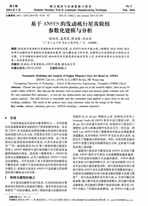
基于ANSYS的发动机行星齿轮组参数化建模与分析
Hale Waihona Puke Pa r a me t r i c Mo d e l i ng a nd Ana l y s i s o f En g i n e Pl n e a t a r y Ge a r S e t Ba s e d o n ANS YS
文章编号 : 1 0 0 1 — 2 2 6 5 ( 2 0 1 4 ) 0 2— 0 1 2 9— 0 2
D O I : 1 0 . 1 3 4 6 2 / j . c n k i . mm t a m t . 2 0 1 4 . 0 2 . 0 3 4
基于 A N S Y S的发 动 机 行 星 齿 轮 组 参数化 建模 与分析
第 2期 2 0 1 4年 2月
组 合 机 床 与 自 动 化 加 工 技 术
Mo d ul ar Ma c h i ne To o l& Aut o ma t i c Ma nu f a c t ur i ng Te c h n i qu e
No. 2 Fe b.2 01 4
0 引 言
行 星齿轮组是 发 动机 内重 要 部件 之一 , 它 的性 能
其保 存 为 s t 1或 i g e s等 格 式 文 件 , 再 将 该 文 件 导 入 G e o m a g i c S t u d i o 或 A N S Y S软 件 中 进行 模 拟 分 析 。但 是i g e s 导人存 在着许 多 的不足 , 特别 是 对于 复杂 的三 维模 型 , 在导人转 换 过程 中往 往 会丢 失 一些 信 息 , 例 如导入在 A N S Y S中的三 维模 型有 时候 会 出现 重 叠线 或重叠 面 , 从而导 致 在 A N S Y S中无 法 自动生 成 体 , 也 就丢失 了重叠部 分 的线或 面 。所 以 , 本 例采取 直 接在 A N S Y S 里建 立简化后 的模 型进行 分析 , 这样 就 可 以避
齿轮Kisssoft全实例教程-2024鲜版

软件内置先进的齿轮分析算法,可对齿轮的强度、刚度、疲劳寿命等 进行精确计算,为设计者提供可靠的参考依据。
丰富的齿轮库
Kisssoft软件自带丰富的齿轮库,包含各种标准和非标准齿轮,方便 用户快速调用和修改。
灵活的参数化设计
软件支持参数化设计,用户可通过修改参数快速调整齿轮结构,提高 设计效率。
Chapter
2024/3/28
19
齿轮参数优化
选择齿轮类型
根据实际需求,选择适合的齿 轮类型,如直齿、斜齿、锥齿
等。
2024/3/28
确定齿轮参数
输入齿轮的模数、齿数、压力 角等基本参数。
优化设计变量
以齿轮的模数、齿数、变位系 数为设计变量,进行优化设计 。
目标函数设定
以齿轮的传动效率、噪声、振 动等性能指标为目标函数,进
实体建模与装配
分别将蜗杆和蜗轮的齿廓曲线 转化为三维实体模型,并进行 装配操作。
设计参数设置
包括模数、蜗杆头数、蜗轮齿 数、导程角等参数设定。
2024/3/28
蜗轮轮廓绘制
根据蜗杆的齿廓曲线和蜗轮齿 数,绘制蜗轮的齿廓曲线。
模型检查与优化
对装配后的模型进行干涉检查 、齿形修正等优化操作。
14
04
齿轮分析实例
查看分析结果
Kisssoft将生成详细的分析报告,包 括齿轮的强度、安全系数等关键指标 。
05
04
运行分析
启动Kisssoft的分析计算功能,对齿轮 进行强度分析。
2024/3/28
16
齿轮疲劳寿命分析
导入齿轮模型
与强度分析相同,首 先需要在Kisssoft中 导入齿轮模型。
选择疲劳寿命分析
基于Solidworks的行星齿轮的三维建模与运动仿真
北京工业大学耿丹学院毕业设计(论文)基于Solidwork的行星齿轮的三维建模与运动仿真所在学院专业班级姓名学号指导老师年月日摘要行星齿轮减速器是一种至少有一个齿轮的几何轴线绕着固定位置转动圆周运动的传动,变速器通常和若干行星轮和传递载荷的作用,为了使功率分流。
渐开线行星齿轮传动具有以下优点:传动比大,结构紧凑,体积小、质量小,效率高,噪音低,运转平稳,因此被广泛应用于冶金,工程机械,起重,运输,航空,机床,电气机械及国防工业等部门,作为减速、变速或增速的齿轮传动装置NGW型行星齿轮传动机构的传动原理:当高速轴由电机驱动,带动太阳轮,然后带动行星轮转动,内齿圈固定,然后带动行星架输出运动的,在行星架上的行星轮既自转和公转,具有相同的结构。
二级,三级或多级传输。
NGW型行星齿轮传动机构主要由太阳齿轮,行星齿轮,内齿圈,行星架,命名为基本成分后,也被称为zk-h型行星齿轮传动机构。
本设计是基于行星齿轮结构设计的特点,和SolidWorks三维建模和运动仿真。
行星齿轮和各种类型的特性的比较,确定方案;其次根据输入功率,相应的输出转速,传动比的传动设计、总体结构设计;三维建模并最终完成了SolidWorks,和模型的装配,并完成了传动部分的运动仿真和运动分析。
关键词:行星齿轮减速器、运动仿真、装配、三维建模AbstractPlanetary gear reducer is driving a at least one gear geometric axis rotated around a circular motion of fixed position, the transmission is usually and planetary gear and transfer load, in order to make the power split. Involute planetary gear transmission has the following advantages: large transmission ratio, compact structure, small volume, small mass, high efficiency, low noise, smooth operation, so it is widely used in metallurgy, engineering machinery, lifting, transportation, aviation, machine tools, electrical machinery and defense industry and other departments, as gear reducer, gear or the growthThe transmission principle of NGW type planetary gear transmission mechanism: when the high-speed shaft driven by a motor, to drive the sun gear, and the planet wheel is driven to rotate, the inner gear ring is fixed, and then drives the planetary frame outputting motion, on the planet carrier planet wheel both rotation and revolution, has the same structure. The two level, three level or multilevel transmission. The NGW type planetary gear transmission mechanism mainly consists of a sun gear, planet gear, inner gear ring, a planetary frame, named after the basic components, also known as the ZK-H type planetary gear transmission mechanism.This design is the design of planetary gear structure based on SolidWorks, and 3D modeling and motion simulation. Comparison of characteristics of planetary gears, and various types of determination scheme; secondly according to the input power, the output speed of the overall design, transmission design, ratio; 3D modeling and finished SolidWorks, assembly and model, and the motion simulation and motion analysis of the transmission part.Keywords: planetary gear reducer, assembly, motion simulation, 3D modeling目录摘要 (1)Abstract (3)第1章绪论 (6)1.1 国内外的研究状况及其发展方向 (6)1.2 SOLIDWORKS行星齿轮的选题分析及设计内容 (7)1.3 主要的工作内容 (7)第2章 NGW型行星轮减速器方案确定 (9)2.1 机构简图的确定 (9)2.2 周转轮系部分的选择 (9)2.3 NGW型行星轮减速器方案确定 (9)2.4 行星轮系中各轮齿数的确定 (12)第3章 NGW型行星减速器结构设计 (14)3.1 基本参数要求与选择 (14)3.1.1 基本参数要求 (14)3.1.2 电动机的选择 (14)3.2 方案设计 (14)3.2.1 机构简图 (14)3.2.2 齿形及精度 (15)3.2.3 齿轮材料及性能 (15)3.3 齿轮的计算与校核 (16)3.3.1 配齿数 (16)3.3.2 初步计算齿轮主要参数 (16)3.3.3 按弯强度曲初算模数m (19)3.3.4 齿轮疲劳强度校核 (20)3.4 轴上部件的设计计算与校核 (26)3.4.1 轴的计算 (26)3.4.2 行星架设计 (31)3.5 键的选择与校核 (35)3.5.1 键的选择 (35)3.5.2 键的校核 (36)3.6 联轴器的选择 (37)3.7 箱体尺寸及附件的设计 (38)第4章 SOLIDWORKS的建模与运动仿真 (43)4.1 建模软件的介绍 (43)4.2 行星齿轮机构的建模 (43)4.2.1 对行星齿轮的建模 (43)4.2.2 行星齿轮其他部件的建模 (45)4.3 行星齿轮机构的虚拟装配 (47)4.4 装配体的实现 (58)4.5 减速机的运动仿真 (60)4.5.1 仿真一般步骤 (60)4.5.2 机构运动分析的任务和方法 (61)4.5.3 运动的生成 (62)4.5.4 运动分析 (62)总结 (64)参考文献 (65)致谢 (66)第1章绪论1.1 国内外的研究状况及其发展方向国内对行星齿轮传动比较深入的研究最早开始于20 世纪60 年代后期,20 世纪70 年代制定了NGW 型渐开线行星齿轮减速器标准系列JB1799-1976。
基于SolidWorks的行星齿轮机构运动仿真模型
基于SolidWorks的行星齿轮机构运动仿真模型发表时间: 2009-2-6 作者: 崔利杰龚小平李玉超来源: 万方数据关键字: CAE运动仿真行星齿轮机构 SolidWorks 二次开发 COSMO对SolidWorks软件进行了二次开发,实现了渐开线齿轮的精确建模,建立了某型直升机主减速器内两级行星传动机构在SolidWorks软件中的装配体模型,应用COSMOSMotion软件进行了机构运动仿真,为机构设计提供了一种高效、直观的仿真手段,提高了行星齿轮传动机构的分析设计能力。
引言行星齿轮传动以其结构紧凑,承载能力强和较低的轴承载荷广泛应用于航空、船舶、汽车、冶金等各个领域。
特别是由于特殊的工作环境,行星齿轮传动仍然占据当今世界直升机主减速器系统中的主流地位。
目前,以数字化装配和计算机仿真分析为主要内容的虚拟样机技术在机械设计与制造中得到了广泛应用,但由于行星齿轮结构相对复杂、行星齿轮同时具有内啮合和外啮合,需要相当精准的造型和装配技术,因此构建行星齿轮机构虚拟样机显得相对困难。
基于此,本文利用SolidWorks软件强大的建模功能和二次开发能力,以某型直升机主减速器内两级行星齿轮传动机构为例,构建了行星齿轮机构模型,结合SolidWorks 内嵌的COSMOSMotion软件完成了其运动仿真。
1齿轮模型的生成1.1 SolidWorks二次开发简介SolidWorks是基于Windows平台的三维机械设计软件,它的设计数据可以全部在外部通过API接口修改。
SolidWorks提供的API接口有OLE技术和COM组件两种形式,为用户提供了强大的二次开发功能。
具有OLE编程和COM接口编程的开发工具,如Visual C++.Visual Basic,Delphi等均可用于SolidWorl国的二次开发,创建出用户定制的、专用的SolidWorks功能模块。
除此之外,SolidWorks还提供了内置的宏命令编程,使得SolidWorks的定制更加容易。
基于KISSsoft的塑料齿轮传动设计探究

122研究与探索Research and Exploration ·工艺与技术中国设备工程 2018.05 (下)1 塑料齿轮传动系统齿轮的应用具有非常久远的历史,而随着技术的发展,齿轮的材料也不在局限于金属,塑料齿轮的应用越来越多,塑料齿轮于金属齿轮相比在成本、设计、加工和性能等多方面都具有明显的优势,目前塑料齿轮的应用越来越广泛,尤其是在一些对精密等级要求较高的领域,如空调系统的减震驱动器、天线传动和监控传动等领域。
气辅法和注射压缩模塑法等新工艺和缩醛类、PBT 和聚酰胺新材料的出现,使塑料齿轮的性能还在不断的提升,将会在社会生产生活的众多领域有更加重要的应用。
随着齿轮传动系统运行速度的不断发展,进行具有优异性能的齿轮传动系统的设计工作变得十分重要,在齿轮的设计过程中计算量非常庞大,应用传统的计算方法难以满足运算的要求,因此需要借助计算机软件来进行计算。
Kisssoft 软件是一种具有强大功能的专业传动系统的设计软件,其不仅拥有十分强大的设计计算功能,而且在计算分析能力、界面优化等方面也十分的出色,因为具有这些特点也使其具有十分广泛的应用。
其中,在齿轮传动系统的设计过程中,应用 KISSsys 模块能够为设计工作提供便捷的建模以及计算方法,从而能够极大的提升计算的精度,减少设计人员的工作量,从而促进整体的设计效率的提升。
2 齿轮传动系统设计齿轮传动系统的设计是一项十分复杂的过程,为了提升系统的性能,就需要保证设计方案具有非常高的精确性,使得传动参数得到最优的设计。
为了实现上述的要求,采用一种高效并且简便的设计方法来进行系统的设计工作十分有必要,这不仅能够保证系统的性能,还能够促进设计工作效率的提升。
Kisssoft 软件是一种十分强大的专业设计软件,对于提升齿轮传动系统的设计工作具有重要的作用。
2.1 塑料齿轮传动模拟建模在天线传动系统中,塑料齿轮的材料多元用聚甲醛(POM)和尼龙(PA66),这是由于这两种材料具有高强度、高耐磨性和良好的抗疲劳性。
kisssys入门实例教程2
KISSsys Tutorial: Two Stage Planetary GearboxUsing this tutorialThis tutorial illustrates how a two stage planetary gearbox can be modelled in KISSsys. Some modelling techniques where special attention and knowledge are required are described in detail.It is recommended that the user completes the first tutorial, KISSsys-Tutorial-001 (modelling of a two stage helical gearbox), before this tutorial is used.The model described here can be further refined. For this, a series of instructions exists, however, their application requires some experience with KISSsys.If questions arise when working through this tutorial, contact the KISSsoft support using the address given above.K I S S s y s T u t o r i a l : T w o S t a g e P l a n e t a r y G e a r b o xTable of contentsTASK (2)1 MODELLINGTHEMODEL (2)2 BUILDINGKISSsys (3)2.1 Starting2.2 Modelling the first stage (3)2.2.1 Machine elements, shaft analysis modules (3)2.2.2 Connections (4)2.2.3 Planetary gear calculation (5)2.3 Modeling the second stage (6)2.4 Positioning the planetary shafts/bolts (7)2.5 Power input, power output, connecting the two stages (8)2.6 Input of gear data (9)2.7 Input of the shaft geometries (11)2.7.1 Sun shafts (11)2.7.2 Planet carrier (12)2.7.3 Shaft for ring gear / gearbox casing (12)2.7.4 Planetary shaft / bolt (13)INTERFACE (15)3 USER3.1 Adding an user Interface (15)3.1.1 Input and output power (15)3.1.2 Adding functions (16)3.1.3 Information on the strength analysis of the gears (18)functionality (20)3.2 Additional3.2.1 Shaft-hub connection calculation (20)3.2.2 Load spectra (21)3.2.3 Position of the ring gears (21)4 SPECIALITIES (22)4.1 Speed of planetary bearings (22)4.2 Number of planets (22)structure (23)4.3 Treeanalysis (23)4.4 Shaft1Modelling taskA KISSsys model for the analysis of a two stage planetary gearbox with integrated gear, shaft and bearing calculation should be built. The model can then be used for design, optimisation and rating of such a system. Note:-The two ring gears shall have zero speed-The planetary gear of the first stage shall be supported by two bearings arranged symmetrically on the planetary bolt-The planetary gear of the second stage shall be supported by a single bearing on the planetary bolt (sitting in the centre of the planetary gear)2Building the modelThe new system is modelled from elements such as gears, shafts, bearings and so on and includes the corresponding KISSsoft analysis. The elements and analysis modules are taken from a library, the so called …Templates“. For the descriptions given below, it is assumed that the user has already completed and understood the first KISSsys tutorial on modelling a two stage helical gearbox.2.1Starting KISSsysFirst, a project folder has to be created. Then, KISSsys is started using Windows-Start/Programs/KISSsoft 03/2008 /KISSsys and the intended folder is choose as project folder.Using menu “Extras”, activate the administrator modus. Then, the templates should be opened using “File/Open templates…”.2.2Modelling the first stage2.2.1Machine elements, shaft analysis modulesFrom the templates, the elements shown below are copied and arranged (note that the shaft element representing the planetary bolt should be placed underneath the planet carrier shaft). Add a special component from templates “kSysPlanetCarrierCoupling” under “sc” shaft called “cc”. This component will define in the program the carrier component and the number of planet shafts.Figure 2.2-1 Building the model, first step, first stageNote that when adding the KISSsoft shaft analysis for each shaft element, a dialog appears where the shaft to be analysed has to be chosen. Also, choose …Save file in KISSsys“ in the same dialog.Furthermore, under coupling element “cc” is a variable …NofPlanets“ of type …Real“ where user can change number of planet shafts in system. Access to the variable from tree – cc – Properties – NofPlanets.Figure 2.2-2 Creating the variable …NofPlanets“ for defining the number of planets in the stage. Here, three planets are present2.2.2ConnectionsNow, the connections are added. Copy the element “kSysPlanetaryGearPairConstraint“ from the templates) and insert it two times into the group “Stage1”. One time for the connection between sun and planet named “zszp”, one time for the connection between planet and ring named “zpzr”:Gear 1: Sun (zs) Gear 2: Planet (zp) Gear 1: Planet (zp) Gear 2: Ring (zr)Figure 2.2-3 Adding the planetary connections The KISSsys model should now look as follows:Figure 2.2-4 KISSsys model with connections added2.2.3Planetary gear calculationFrom the templates, the planetary gear calculation “PlanetGearSet” from “kSoftCalculations/withSystem” is imported and added underneath the group “Stage1” and called “GP1”. In the dialog, the two connections and the saving mode for the KISSsoft data have to be defined:Figure 2.2-5 Adding the planetary gear set calculationThe KISSsys model should now look as follows:Figure 2.2-6 KISSsys model with planetary gear set calculation added2.3Modeling the second stageThe first stage which has been created above is now copied and pasted in the same level of the tree structure using the name …Stage2”:Figure 2.3-1 Copy the first stage and paste it as second stageThe KISSsys model should now look as follows:Figure 2.3-2 KISSsys model with two stagesThe second stage now has to be positioned in space with respect to the first stage. Using “Dialog” in the group “Stage2” (right mouse click on “Stage2”), the second stage can be positioned (e.g. using 200mm distance in axial direction):Figure 2.3-3 Positioning the second stage with respect to the first stage2.4Positioning the planetary shafts/boltsThe planetary shafts of the two stages now have to be positioned in space. For this, use “Dialog” (right mouse click on the planetary shaft elements) to position them parallel to the respective sun shaft in a distance equal to the centre distance of the gear pair sun-planet and axial distance e.g. so that gears will be always in the same place:Figure 2.4-1 Positioning the two planetary shafts with respect to the corresponding sun shaft2.5Power input, power output, connecting the two stagesThe planet carrier of the first stage (power output of the first stage) has to be connected with the sun shaft of the second stage (power input of the second stage). For this, use a coupling constraint from the templates (kSysCouplingConstraint), adding as shown below:Figure 2.5-1 Configuration of the connection of the two stagesThis connection can be called e.g. “StageConnection”.Using …kSysSpeedOrForce“ elements (copied from the templates), power is put into the system / taken from the system (the power input shall be the coupling on the sun shaft of stage 1, power output shall be the coupling on the planet carrier of the second stage). The two ring gears are constrained again using …kSysSpeedOrForce“elements.In this example, speed and torque are defined forthe power input (sun shaft of first stage).Therefore, for the power output (planet carrier ofsecond stage), no additional kinematic constraintmay be defined.The speed of the ring gear of stage 1 is set to zero The speed of the ring gear of stage 2 is set to zeroFigure 2.5-2 Adding …kSysSpeedOrForce“ elements to define the kinematic boundary conditionsNow, the kinematic calculation can be tested by calling the function …Calculate Kinematics“ in menu (a mouse click). At the lower end of the screen, a message …Kinematic calculated“ should appear. Now, press …Refresh All“ (symbol number eight from the left side in the menu bar, see mark below).The KISSsys model should now look as follows:Figure 2.5-3 KISSsys model, modeling of the structure completed2.6Input of gear dataNow, the gear data can be defined in the respective KISSsoft planetary gear calculation can be defined. For this, double click on …GP1“ for stages 1 and 2 to get to the respective KISSsoft interface. Here, the gear data can either be defined or a suitable gear set can be sized using the sizing functions in the usual manner. It is alsopossible to use an existing gear set by using File/Open. Please ignore the follow warning, because it’s just information for the gear calculation.Figure 2.6-1 Input of gear date in KISSsoftThe number of planets used however is not defined using the KISSsoft interface but is defined through KISSsys (using the value given in the variable …NofPlanets“). The number defined previously is now shown in KISSsoft: In order to get a 3D representation of the system modelled, the element“kSys3DView“ has to be copied from the templates and pasted underneath …System“. Using …Show“ (right mouse click), the 3D windows shows:Figure 2.6-2 3D viewThe ring gears are not visible yet. For this, go to the two ring gears and add a value to the variables “di” (use negative values since this is an inner gear). You may e.g. use formula df-10*mn, instead of fixed valueFigure 2.6-3 Definition of the outer diameter (index …i“ since it is in fact the inner diameter) for the ring gearThe 3D graphics should now look as follows:Figure 2.6-4 3D view with ring gears2.7Input of the shaft geometries2.7.1Sun shaftsSupport sun shaft “ss” on Stage1 rigidly on left end. To do this add new component “kSysBearing” on the shaft “ss” in Stage1 and call it “b1”. Use “UpdateShaftElements” function from tree under“SS” calculation to add bearing on the shaft. On double click on …SS“, get to the KISSsoft interface for the shaft analysis. Using the graphical shaft editor, the sun shaft can be defined , e.g. using the simple geometry shown below:Figure 2.7-1 Defining the sun shaftNote that the sun is present several times on the sun shaft (as many times as planets are present) to simulate the multiple contacts between the sun gear and the several planets (such that the radial forces on the sun shaft are equal to zero). You may now model the second sun shaft similarly, but use e.g. two normal bearing to support the shaft (kSysRollerBearing).Figure 2.7-2 Defining the sun shaft2.7.2Planet carrierModelling the planet carrier is not necessary for the analysis of the gearbox and is hence not described here. Note! If you don’t want to define data for the carries, please remove calculation modules “SC” from the tree to avoid error messages. When geometry is created, please remember to add also sufficient supports.2.7.3Shaft for ring gear / gearbox casingThe shaft for the ring gear is the same as the casing of the gearbox. It is not necessary to model it.2.7.4Planetary shaft / boltIn this example, the planet of the first stage is supported by two bearings (arranged symmetrically). The planet of the second stage is supported by a single bearing. The modelling of the two shafts / bolts is therefore different.First, the bearings (…b1“, …b2“) and the respective bearing calculations (…Bearing2“, …Bearing1“) have to be added to the tree structure. Note that for the first planetary stage a bearing calculation element for two bearings should be used (“Bearing2” in templates, from “kSoftCalculations/withSystem”), whereas for stage 2, a bearing calculation element for one bearing should be used (…Bearing1“ in templates, from “kSoftCalculations/withSystem”). For the 2nd stage planet pin add also “kSysBearing” to create rigid support on left side.Figure 2.7-3 Tree structure with bearings and bearing calculations addedSince new elements have been added to the shafts, use …UpdateShaftElements“ (right mouse click on …SP“) in order to have these newly added elements (the bearings) present in the graphical shaft editor in KISSsoft. Now, KISSsoft can be used (double click on …SP“ on both stages) to model the planetary shafts. It is recommended that the second bearing (on the planetary shaft of stage 1) is positioned first on e.g. 5mm so it can be distinguished from the first bearing (initially, they both have the same position, y=0 mm and they can hence not be distinguished in the graphical shaft editor).In this example, the two bearings of the second stage shall be positioned symmetrically with respect to the centre of the planetary gear. In which distance to the centre of the gear the bearings are placed does not matter since the radial force of the planet is distributed equally on the two bearings (as long as the planetary gear has not helix angle, if the planetary gear has a helix angle, the bearings have to be positioned at the correct distance from the centre of the gear since a moment from the radial force and the helix angle results). After the definition of the planetary shaft / bolt use “Calculate F5”.Figure 2.7-4 Support of the planet of the first stage. The objective is to have an even distribution of the force acting on the planetary gear on the two bearings. As long as there are only radial forces acting, the distance from the centre of the gear to the bearing does not change the result as long as the bearings are positioned symmetrically. The bearing of the second planet is to be placed in the centre of the gear. Since only one bearing is present, the system is not statically defined yet. Therefore, a second boundary condition is necessary for the shaft. Use support element to fix shaft from the left shaft end.Figure 2.7-5 Arrangement for second planetary shaftFigure 2.7-6 Shaft end on the left sideIn the 3D view, the bearings are at first not visible. For this, go to the KISSsoft bearing calculations and press …Calculate F5“ in order to update the bearing data. Using “Refresh “, the bearings should then become visible.Figure 2.7-7 3D view of the gearbox3User Interface3.1Adding an user InterfaceIn order to simplify the management of the KISSsoft calculations, a user interface is used allowing for input and output of values. For this, copy a table …UserInterface“ from the templates into the tree structure (beneath …System“). Using right mouse click and …Show“, the table is shown. Using …Dialog“ the number of rows and columns can be modified.3.1.1Input and output powerIn this example, the torque and the speed are defined for the input (sun / sun-shaft of stage 1). Add a descriptive text in the user interface (just type it in a field), e.g. …Input speed“ and …Input torque“. To add the values, use right mouse click on the next field and select …Insert Real“. Now, press “Reference” and define the variable which shall be addressed:Figure 3.1-1 Defining the input speedFigure 3.1-2 Defining the input torqueAdditional values (output) can be added1.Input power: press right mouse click in a field, select …Insert Real“ and use the variable name…Input.power“ in …Expression“2.Output speed: as described above, variable name to be used …Output.speed“3.Output torque: as described above, variable name to be used …Output.torque“4.Output power: as described above, variable name to be used …Output.power“5.Ratio: use the following expression in …Expression“: abs(Input.speed/Output.speed), Where “abs”returns the absolute value of the expression in brackets.The user interface then looks as follows:Figure 3.1-3 User interface with information and input regarding the kinematics of the gear box3.1.2Adding functionsIn the user interface, three different functions shall be available: Calculation of the kinematics, execution of the KISSsoft calculations and generation of the KISSsoft calculation reports. For this, three functions …Kinematic“, …Strength“ and …Write Reports“ are added to the User Interface (right mouse click on the field of choice, choose …Insert Function“ and define the following)Note! User is also able to use these functions from menu, using shortcut buttons.Figure 3.1-4 Calculation of kinematic followed by …Refresh All“Figure 3.1-5 Before the KISSsoft calculations are executed, the kinematics are calculatedFigure 3.1-6 Writing the KISSsoft reports (saved into the KISSys project directory)3.1.3Information on the strength analysis of the gearsFurthermore, in the user interface, the required lifetime of the gears and the resulting safety factors (minimum value for sun, planet, ring, for root and flank) shall be shown. The required lifetime is stored in the variable …H“ of the KISSsoft calculation for the planetary gear set. To add it to the user interface, use right mouse click on the field of choice, select …Insert Real“, …Reference“ and …Reference to“ …Stage1.GP1.H“. With this the value given in the user interface will be forwarded to the variable “H”. For the second stage, the same lifetime is required (in this example). In order to have the second stage calculated with the same lifetime as the first, add …Stage1.GP1.H“ in …Expression“ in variable …Stage2.GP1.H“. This will set the required lifetime of the secondstage equal to the required lifetime of the first stage:Figure 3.1-7 Connecting the required lifetime of the second stage to the required lifetime of the first stageIn the User Interface the resulting minimal safety factors are added. The safety factors for the gear pairs (sun-planet, planet-ring) are stored in the variables SF1, SF2, SF3 (root) and SH1, SH2, SH3 (flank). For the UserInterface the minimum of these values is used:Figure 3.1-8 Output of the minimal safety factor, stage 1 rootFigure 3.1-9 Output of the minimal safety factor, stage 1 flankNote: In the variable …SFmin“ and …SHmin“, the required, not the minimal, lifetime is given. The index used is somewhat misleading!The user interface should then look – once the KISSsoft calculations have been executed through double click on “Strength” to generate results as follows:Figure 3.1-10 User interface with required lifetime and some basic results (minimal safety factors)3.2Additional functionality3.2.1Shaft-hub connection calculationThe power input of the gearbox, the coupling on the first sun shaft, should be modelled using a key/keyway. The corresponding calculation is to be added to the tree structure. For this, copy the KISSsoft calculation …FeatherKey“ from the templates and add it to …Stage1“. In the dialog, choose the coupling where the key is used and choose …Save file in KISSsys“.Figure 3.2-1 Copy the key analysis from the templates and paste it into the tree structureFigure 3.2-2 Choose the respective coupling and saving mode in the dialogSome parameters of the key analysis are now taken from the KISSsys system. These are the torque (for nominal torque) and the shaft diameter (see markings in Figure 3.2-3). Using double click on the KISSsoft calculation, the key calculation is shown. Here, the key calculation can be defined completely.Note that the length of the key is equal to the length of the coupling used. The length of the coupling can be defined using the variable “b” of the coupling element “cIn” on the sun shaft.Figure 3.2-3 KISSsoft key analysis. Some values are defined from KISSsys directly3.2.2Load spectraA load spectrum can be used for analysis. See “ins-301-LoadSpectrum-templates.pdf”3.2.3Position of the ring gearsPosition of the ring gear can be set according to the sun in axial direction using function l_p(reference,point on parent element). Because shaft for the rings are not defined ring gears can be set correctly for graphical presentation. Open ring gear properties “zr” from tree there a variable “position” is available. Set expression for this as follows “l_p(ss.zs,{0,0,0})*{0,1,0}”. This will automatically set position of the ring to be same as for thesun in the coordinate system.Figure 3.2-1 Set position definition for the ring gear according to the sun gear4Specialities4.1Speed of planetary bearingsThe speeds calculated for the planetary bearings are absolute speeds (revolutions in space) with reference to a co-ordinates system which is fixed in space. However, the bearings / planetary shafts rotate with the speed of rotation of the planet carrier in space. For the calculation of the lifetime of the planetary bearings, the relative speed with respect to the planetary shaft (relative speed of outer ring of bearing to inner ring of bearing) is relevant. The planet shaft, in turn rotates with the speed of the planet carrier. The speed of the planetary bearings therefore has to be corrected as follows:Relative speed planet compared to planet-shaft (Outer ring of bearing compared to inner ring)=Absolute speed of planet (speed of outer ring of bearing) – absolute speed of planet carrier / planet-shaft (speed of inner ring of bearing):Figure 4.1-1 Initial bearing speed (shown for first stage)Figure 4.1-2 Corrected speed, shown for first stage, corresponding expression for second stageNote: set the flag “KISSsys->KISSsoft” and de-activate the flag “KISSsoft->KISSsys” since the value of the bearing speed shall be calculated in KISSsys only and not be defined in KISSsoft directly.4.2Number of planetsIn the coupling element of the planet carrier (…cc“), the number of planets for each stage can be modified using the variable …NofPlanets“. After changing this value, use “UpdateShaftElements” for all sun and ring shaft calculations in order to update the number of gear contacts.4.3Tree structureIt is strongly recommended to use the tree structure as shown above. Especially the planetary shafts should be arranged underneath the planet carrier shafts such that the rotation of the planetary shafts in space is calculated correctly.4.4Shaft analysisIf a shaft analysis (KISSsoft calculation) is added underneath a shaft element (KISSsys element) in the tree structure, a shaft geometry has to be defined in the graphical shaft editor. If no shaft geometry has been defined (as in this example for the carrier shafts and the ring shafts), a message will show when the KISSsoft calculations are executed (e.g. by double click on “Strength” in the user interface)This is not an error message and the kinematic calculation and all other KISSsoft calculations (e.g. the gear calculations) are still executed correctly and will give correct results.There are three ways to avoid this message:-The most dangerous way is to simply suppress the messages. For this, go to “Extras” in the KISSsys menu bar and choose …Suppress Messages“. Note that now all messages, even error messages are now suppressed. Using KISSys is still possible but not recommended...-All shaft geometry are defined, including the geometry of the planet carrier and the ring gear shaft / casing. This has the advantage that the 3D view looks very realistic.-Those shaft calculations which are not necessary are removed from the tree structure. A shaft calculation is necessary only if the shaft itself is to be calculated (e.g. in terms of fatigue strength) or if a bearing calculation is to be performed. In the latter case, the shaft analysis is necessary since it is in the shaft analysis where the bearing forces are calculated. These bearing forces are then used in the bearing calculation module for the lifetime calculation of the bearings. In this example, only the sun and planet shafts needed to be modelled in fact. In the most extreme case, if only the gear analysis is of interest and no bearings or shafts should be calculated.Again: there is a difference between the KISSsys shaft element …kSysShaft“ and the corresponding KISSsoft shaft calculation …Shaft“. The first is necessary for calculation of the kinematics and is used when building a model. It represents a machine element. The calculation is only necessary if e.g. a strength analysis of the above machine element is required.Figure 4.4-1 Left: KISSsys shaft element, right: KISSsoft shaft analysis。
kisssort圆柱齿轮结果分析
KISSsoft软件常规齿轮强度计算
如下图,为经典的齿轮材料(金属材料的属性一般 差异性不是很大,而塑料各材料之间则比较大)S—N曲 线。
金属
KISSsoft给出的S—N曲 线
塑胶
5
KISSsoft软件常规齿轮强度计算
如下图塑胶S—N曲线所示,当Cycle 大于10 ³ 时, 应力Stress开始会有明显的降低,当Cycle 大于10 6时, 应力降低到原来的一半,从而可以从曲线分析齿轮的使用 寿命.
二、关于传动系统中,最关键的零件就是齿 轮,由于齿轮的形状比标准试棒复杂,对齿轮热 处理方式不同,使用时润滑油的情况也不相同, 这些因素就会使得齿轮材料的疲劳特性与标准试 棒的疲劳特性产生很大的差异。因此,对不同材 料和形状的齿轮,进行专门设计和制造,使用专 门的润滑油,在专门的实验台架上按规定的流程 进行齿轮材料测试,得到材料的S—N曲线和弯曲 S—N曲线,才能真实反映齿轮材料实际的接触和 弯曲疲劳特性。
+/-/+
8
KISSsoft软件常规齿轮强度计算
滑动比范围工况分析
一般来说,滑动比的参考值在以下四种区间内会有不同的齿 轮啮合情况:
9
KISSsoft软件常规齿轮强度计算
KISSsoft软件关于滑动比图形的应用
通过变位系数优化滑动比的数值!
上图为外啮合齿轮滑动系数曲线,由 图中可以看出,若将实际啮合线B1B2向左 移动,即可减小η1max,这可以通过变位 齿轮来实现,适当选择变位系数,可以减 小滑动系数值并可使η1max=η2max
14
KISSsoft软件常规齿轮强度计算
五、闪温(Flash temperature)分析
齿顶刚啮合 处瞬时温度 的变化(逆 时针)
基于KISSsoft行星减速轮系的修形优化设计
Key words: planetary gear; KISSsoft; gear transmission; gear modification
0 引言
装误差,使得齿轮传动装置的振动和噪声往往比较大。
研究行星齿轮传动运动学的主要任务之一,设计行星齿
轮传动时根据所给定的传动比 i p 的大小来分配各齿轮的齿数[4]。
在国内现阶段,尚未形成齿轮修形技术的统一规范,各
本文研究的行星轮系传动,由齿箱壳体上固定的内齿圈,齿
研究人员主要采用下述 4 种方式对齿轮进行修形 :(1) 通过
1.25
1.25
1
1
1
C45,调质钢淬火 C45,调质钢淬火 C45,调质钢淬火
输入太阳轮转速 1 000 r/min
修缘、修根和挖根等。在齿轮啮合传动过程中,齿轮副会产
生相应的弹性变形,轮齿啮入时的啮合力会猛然增大,产生
行星轮系基本参数
其他
采用浸油润滑,润滑油采用 ISO-VG 220
根据计算方法 ISO 6336:2006 方法 B 计算
圈中心驱动太阳轮及内齿圈和太阳轮之间一组由 3 个行星齿轮
[1]
经验公式计算修形量;(2) 应用有限元方法,通过理论计算
等组成的行星齿轮组。其各轮齿齿数与传动比的关系式如下:
优化;(3) 基于接触有限元理论,应用有限元软件对齿轮变
形进行接触分析;(4) 通过寻找目标函数对修形参数进行优
iaxb = 1 - iabx = 1 +
表4
修行后该行星轮系的计算结果
中级篇:行星轮设计在KISSsoft软件中的应用
1 / 59ຫໍສະໝຸດ 录一、前言 ................................................................................................................................................................................................. 4 二、行星轮计算模块 .......................................................................................................................................................................... 4 (1)现成案例设计数据列举 .......................................................................................................................................................... 5 (2)参数在软件界面中的输入 ..................................................................................................................................................... 5 (3)现有案例基础上的优化............................
基于KISSsoft的齿轮加工模拟试验
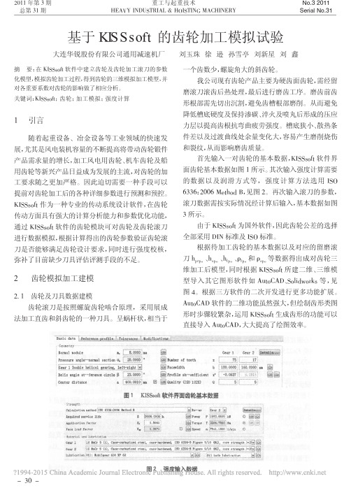
图1KISSsoft 软件界面齿轮基本数据图2强度输入数据摘要:在KISSsoft 软件中建立齿轮及齿轮加工滚刀的参数化模型,模拟齿轮加工过程,得到齿轮的三维模拟加工模型,并对各重要系数对齿轮的影响做了相应分析。
关键词:KISSsoft ;齿轮;加工模拟;强度计算1引言随着起重设备、冶金设备等工业领域的快速发展,尤其是风电装机容量的不断提高将带动齿轮锻件产品需求量的增长,加工风电用齿轮、机车齿轮及船用齿轮等新兴产品日益成为发展的主流,对齿轮的加工要求随之更加严格。
因此迫切需要一种手段可以提前对齿轮加工后的各种详细参数进行预测和预控。
KISSsoft 作为一种专业的传动系统设计软件,在齿轮传动方面具有强大的计算分析能力和参数优化功能,通过KISSsoft 软件的齿轮模块可对齿轮及齿轮滚刀进行数据模拟,根据计算得出的齿轮参数验证齿轮滚刀是否能够满足齿轮设计要求,同时进行强度校核,弥补了目前缺少刀具评估评测手段的不足。
2齿轮模拟加工建模2.1齿轮及刀具数据建模齿轮滚刀是按照螺旋齿轮啮合原理,采用展成法加工直齿和斜齿轮的一种刀具。
呈蜗杆状,相当于一个齿数少,螺旋角大的斜齿轮。
我公司现有齿轮产品主要为硬齿面齿轮,需经留磨滚刀滚齿后热处理,最后进行磨齿工序。
磨齿前齿形根部需先切出沉割,避免齿槽根部磨削。
从而避免降低槽底硬度及保持渗碳、淬火及喷丸后形成的压应力层以提高齿根抗弯曲疲劳强度。
槽底狭小、散热条件差以及过渡曲线处余量变化大,容易产生磨削烧伤和裂纹,从而影响磨齿质量。
首先输入一对齿轮的基本数据,KISSsoft 软件界面齿轮基本数据如图1所示。
其次输入强度计算需要的数据以及润滑方式等,强度计算方法选用ISO 6336:2006Method B ,见图2。
再次输入滚刀的参数,滚刀数据需按实际情况经计算后输入,基本数据如图3所示。
由于KISSsoft 为国外软件,因此齿轮公差的选择全部采用DIN 标准及ISO 标准。
基于kisssoft的行星齿轮修形优化设计
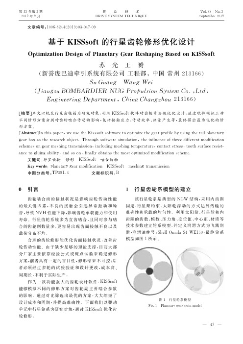
文章编号:1006-8244(2019)03-047-09基于KISSsoft的行星齿轮修形优化设计Optimization Design of Planetary Gear Reshaping Based on KISSsoft苏 光 王 赟(新誉庞巴迪牵引系统有限公司工程部,中国常州213166)Su Guang Wang Wei(Jiangsu BOMBARDIER NUG Propulsion System Co.,Ltd,Engineering Department,China Changzhou 213166)[摘要]本文以轨交行星齿轮箱为研究对象,利用KISSsoft软件对齿轮修形做优化设计,通过软件模拟三种不同修形方案分别对齿轮啮合传动的影响,包括接触应力、传动效率、热量产生等,最终得出最为优化的修形方案。
[Abstract]In this paper,we use the Kisssoft software to optimize the gear profile by using the rail-planetarygear box as the research object.Through software simulation,the influence of three different modificationschemes on gear meshing transmission,including meshing temperature,contact stress,tooth surface resist-ance to gluing ability,and so on,finally obtains the most optimized modification scheme. 关键词:行星齿轮 修形 KISSsoft 啮合传动 Key words:planetary gear modification KISSsoft meshing transmission 中图分类号:TP391.4 文献标识码:B0 引言齿轮啮合面的接触状况是影响齿轮传动性能的最关键因素,不良的接触会引起异常振动和噪音,导致NVH性能下降,影响齿轮承载能力和使用寿命。
kisssoft行星齿轮设计实例

kisssoft行星齿轮设计实例
KISSsoft是一款专业的齿轮设计软件,它提供了丰富的功能和
实例来帮助工程师进行行星齿轮设计。
以下是一个关于行星齿轮设
计的实例:
在行星齿轮设计中,首先需要确定输入和输出轴的转速和扭矩
要求。
然后,根据设计要求选择合适的模数、齿数、齿轮材料等参数。
接着,进行齿轮的几何设计,包括齿形的计算、齿顶圆和齿根
圆的确定等。
在行星齿轮系统中,还需要考虑行星轮、太阳轮和内
齿圈之间的啮合关系,以及轴承的选型和布局等问题。
此外,还需
要进行强度校核、齿面接触分析、齿轮传动效率计算等工作。
最后,进行齿轮系统的动力学仿真和噪声分析,以验证设计的合理性和稳
定性。
除了以上的设计步骤,KISSsoft还提供了丰富的实例和案例,
供工程师参考和学习。
这些实例涵盖了不同类型和规格的行星齿轮
设计,涉及到不同工况和要求下的设计方案。
工程师可以通过学习
这些实例,了解行星齿轮设计的方法和技巧,同时也可以借鉴实例
中的经验和教训,提高自己的设计水平。
总的来说,KISSsoft作为一款专业的齿轮设计软件,提供了丰富的功能和实例来帮助工程师进行行星齿轮设计。
通过学习和应用这些实例,工程师可以更好地掌握行星齿轮设计的技术要点,提高设计质量和效率。
利用kisssoft 建立行星轮

CustomerEES KISSsoft GmbH Weid 10 / P.O. Box 6313 MenzingenSwitzerland www.EES-KISSsoft.ch Title: Pitch & yaw guideline No.: 08-001 Date: 1.1.08 Manager: HD Email: h.dinner@EES-KISSsoft.ch Revision: 0Autor: HDDate: 1.1.08Approved: HDDate: 1.1.08EES KISSsoft GmbH++41 41 755 09 54 (Phone) Neudorfstrasse 22++41 41 755 09 48 (Fax) 6313 MenzingenP.O. Box 121 Switzerland www.EES-KISSsoft.ch1 Principal of a Planetary Stage in KISSsys Exercise 4 1.1 Executive summary This exercise will teach how to build up a planetary stage in KISSsys. We strongly recommend to study the theoretical background of this exercise which is documented in the “Planetary-stage.pdf”.P r i n c i p a l o f a P l a n e t a r y S t a g e i n K I S S s y s E x e r c i s e 41.2 Table of content1Principal of a Planetary Stage in KISSsys Exercise 4 (1)1.1Executive summary (1)1.2Table of content (2)1.3Document change record (2)2Solution (3)2.1Start KISSsys (3)3Adding the machine elements (4)3.1Shafts (4)3.2Planet pin (4)3.3Sun and ring gear (7)3.4Bearings and supports (7)4Adding Kinematic connections (8)4.1Power input and output (8)4.2Connections (9)5Adding KISSsoft data (11)5.1Gear data (11)5.2Shaft and bearing data (14)5.3Coaxiall shaft “ssscsr” (15)5.3.1Sun shaft “ss” (15)5.3.2Carrier shaft “sc” (17)5.3.3Ring gear shaft “sr” (18)Coaxial shaft “sppspr” (20)5.3.4Planet pin shaft “spp” (21)5.3.5Ring body shaft “spr” (22)5.3.6Connection bearing (23)6Graphical representation (24)6.1Add 3D graphics (24)6.2Positioning (25)6.2.1Display internal gear in the 3D-View (26)7User Interface (29)7.1Add user interface (29)7.2Show data in user interface (29)7.2.1Add text into the table (30)7.2.2Add a reference to real value into the table (30)7.2.3Add real value into the table (32)7.2.4User define expression for a real value (34)7.2.5Add a function into the table (35)1.3 Document change recordRevision Dated Who Comments0 2010-112-02 TH Original document2 Solution2.1 Start KISSsysStart KISSsys, select a project folder and change to administrator modus:Open the templates:Add a group “GB” from the templates into the root of the tree structure3 Adding the machine elements3.1 ShaftsAdd the shafts from the templates to the tree structure. We use “ss” for the sun shaft, “sr” for the ring gear shaft and “sc” for the planetary carrier. As in reality these three shafts are all coaxial, be sure to use the element “kSysCoaxialShaft” from the templates!3.2 Planet pinThe planet pin is a subsystem which needs to be modelled in a separate group. Copy a group from the templates and add it onto the carrier shaft “sc” (as the planet is rotating with the planet carrier shaft). Use two coaxial shafts of type “kSysCoaxialShaft” to model the planet pin “spp” and the gearbody “spr”.The planet pin is attached to the planet carrier on both sides. To simulate this, we use two general supports, one on each end of the planet pin. For this, use the “kSysBearing” type of support:Now, add the planet gear (or rather the teeth of the planet gear) onto the planet gear body “spr”:We also need to add a coupling onto the planet pin which will allow the planet pin “spp” to rotate with the same speed as the planet carrier. The same coupling, we will also place on the planet carrier (in a later step, these two couplings will be connected, transmitting the speed of the planet carrier to the planet pin itself). Note that the rotational speed of the gearbody, modelled as a shaft “spr”, will be governed by the planet gear “zp”. For the coupling, make sure that you ue the “kSysPlanetCarrierCoupling” only. Add such a coupling on “spp” and “sc”.The gearbody, represented by the shaft “spr” and the pin, represented by the shaft “spp” are connected to each other by two roller bearings. Such a type of roller bearing that uses two shafts is called a “ConnectionRollerBearing”. Use from the templates the element “kSysConnectionRollerBearing” and add them into the group “sp”. A dialog will then ask onto which shaft the outer race is to be attached and on which shaft the inner race is to be attached. In our example, the planet pin, “spp”, is connected to the inner race of the bearing and the planet gear body “spr” is connected to the roller bearing outer race:3.3 Sun and ring gearNow, add the ring gear “zr” onto the ring gear shaft and the sun gear “zs” onto the sunshaft. Furthermore, use a coupling on the sun gear shaft for the power input and a coupling on the planetary carrier shaft for the power output:3.4 Bearings and supportsThe ring gear shaft “sr” should be constrained with one support of type “kSysBearing” The sun shaft “ss” should be constrained with two supports of type “kSysBearing”The planet carrier “sc” is supported by two roller bearings.4 Adding Kinematic connections4.1 Power input and outputAdd the element “kSysSpeedOrTorque” two times from the tree templates to the tree structure. The input should be connected to the input coupling “cIn” on the sun shaft. Give the speed and torque on the input. The output is connected to the output coupling “cOut” on the planetary carrier shaft. Here, don’t give the speed or torque, these will be calculated from the input speed and torque:4.2 ConnectionsFrom the templates, add a connection “kSysPlanetaryGearPairConstraint” two times. Once call it “zszp” (for the connection of the sun gear “zs” to the planet gear “zp” and once call it “zpzr” for the connection of the planet gear “zp” to the ring gear “zr).”Also, add a connection of type “kSysCouplingConstraint” to the gearbox in order to allow speed information ot be transmitted from the coupling “cpc” on the planetary carrier and “cpc” on the planetary pin.Note that the rotation of the ring gear needs also to be fixed which is also considered a kinematic condition. This requires the rotation of the ring gear around y-axis must be deactivated. We often recommend that all degree’s of freedem are constrainedNow, run the kinematic calculation and you will recognise the kinematics in the schema:5 Adding KISSsoft dataAdd from the template a KISSsoft element with system to the element tree.5.1 Gear dataAdd a PlanetGearSet to the same level as the gear pair connection “zszp” and “zpzr”. Give to the new element following name “zszpzr”. In the upcoming window define the connection for the sun-planet “zszp” and planet-internal gear “zpzr”.Before open the PlanetGearSet run first the kinematics to transfer the input data which is define yet in the input boundary. Now open the PlanetGearSet calculation and double check in the second tab “Strength”, that the amount of speed and torque is the same as given in the input boundary.Use the rough sizing and run the calculationClick with the right mouse button on the white background to get the tab for the weight ”W”. Choose the lightest planetary gear set. In this configuration the lightest solution has a weight of 41.265 kg. Accept and close.Change the facewidth to 70 mm for all gears and run the calculation .Return to KISSsys, without saving the KISSsoft calculation, by closing the window.5.2 Shaft and bearing dataCopy the kSoftCoaxialShafts once to the level “GB” as the sun shaft “ss”, carrier shaft “sc” and ring gear shaft “sr” are located. Give the name “ssscsr” for the calculation. Add a second kSoftCoaxialShaft for the group “sp”, in order for the pin shaft “spp” and for the ring body “spr”. The calculation name is “sppspr”.Run the shaft calculation for the “ssscsr”5.3 Coaxiall shaft “ssscsr”5.3.1 Sun shaft “ss”Start with the sun shaft “ss”Input data for sun shaft “ss”Element Position y Length l Diameter d Freedom Comments Sun shaft “ss” 0Outer contour 1 0 300 80Outer contour 2 300 70 120cIn (Input) 25 50 100zs (zszp) 1 335zs (zszp) 2 335zs (zszp) 2 335u1 25 1-1-1-0-0-0 1=fixu2 335 1-0-1-0-0-0Run the calculation.In reality the sun shaft is supported at two locations. At the sun gear itself it is supported by the planets. This is modelled by adding the support u2 in the middle of the sun gear. The sun gear is free to tilt, to rotate and to move axially. Therefore, for u2, the degrees of freedoms (DOF) in Y direction, rotation in X, in Y and in Z direction are free (“non-locating” in the dialogue below). Only the DOF in X and Z direction are fixed (“fixed” in the dialogue below).Let us assume that the gear box is connected to an electro motor. The electro motor supports the sun shaft in radial and axial direction. Therefore, the translational DOF are fixed and therotational DOF are free.5.3.2 Carrier shaft “sc”Input data for the carrier shaft “sc”Element Position y Length l Diameter d Freedom Comments Carrier shaft “sc” 246Outer contour 1 0 24 200Outer contour 2 24 130 350Outer contour 3 154 100 200Inner contour 1 0 39 170Inner contour 2 39 100 320Inner contour 3 139 115 170cOut (Output) 229 50 220cpc (cpccpc) 89cpc (zpzr) 89cpc (zszp) 89b1 12 left SKF61840 b2 166 right SKF61840 Run the calculation.5.3.3 Ring gear shaft “sr”Input data for ring gear shaft “sr”Element Position y Length l Diameter d Freedom Comments Ring gear shaft “sr” 300 Outer contour 1 0 70 500 Inner contour 1 0 70 425 zr (zpzr) 1 35 zr (zpzr) 2 35 zr (zpzr) 3 35u1 35 1-1-1-1-1-1Run the shaft calculation and following messages will appear.For this example this warning can be ignore. The amount of 0.01 Nm is corresponding to the accuracy of the kinematic calculation.Fixing all DOF for the support of the ring gear shaft means: -It is not rotating (DOF rotational in Y is fixed)-It is not moving in space (All translational DOF are fix) -It is not tilting (Rotational DOF X and Z are fixed.Coaxial shaft “sppspr” Group planet shaft “sp”Input data for planet pin shaft “spp”Element Position y Length l Diameter d Freedom Comments Pin shaft “spp” 0Outer contour 1 0 130 50cpc (cpccpc) 7.5u1 7.5 1-1-1-0-1-0u2 122.5 1-0-1-0-1-0Run the calculationInput data for ring body shaft “spr”Element Position y Length l Diameter d Freedom Comments Ring body shaft “spr” 30Outer contour 0 70 100Inner contour 1 0 17 72Inner contour 2 17 36 65Inner contour 3 53 70 72zp (zpzr) 35 Outputzp (zszp) 35 Input Run the calculation.5.3.6 Connection bearingInput data for the connecting bearingElement Position y Length l Diameter d Freedom Comments b1 (Needle roller bearing)38.5 left KOYO 50NQ7217 b2 (Needle roller bearing) 91.5rightKOYO 50NQ7217Following warning will pop up.For this example this warning can be ignore.6 Graphical representationClick on the refresh button to update all diagram.6.1 Add 3D graphicsGet the kSys3DView from the templates and place it on the root directory from the model.Start the kSys3DView by using the right mouse button and press show to get the 3D-Window.6.2 PositioningTo position the planet gear according to the sun- and ring gear, go the group “sp” and use the right mouse button to get the menu, click on dialog.Choose the gear pair “_O.zszpzr” which to connect to each other.KISSsys will set automatically the formulas, when according to gear pair is chosen. Now refresh the 3DView by pressing the refreshbutton.According to which elementCoordinates system polar or cartesianThis is the center distance between sun- and planet-gear Angle position from the planet according the X-Y plane Y-axis postion where the gears are connected to each otherThe planet gear moved to the correct position in between of the sun and ring gear.6.2.1 Display internal gear in the 3D-ViewOne setting has to be done to display the ring gear. Open the PlanetaryGearSet and addfollowing value.To display the ring gear it has to have a value at least bigger then the result for the internal gear 364.67 mm. Close the KISSsoft calculation and refresh KISSsys with the new datas.To get a better argument to discuss it is possible to change the colour and transparency of each part. Change the colour from the planet carrier.To display the gear details go to 3D-settingselements.7 User InterfaceTo use the benefit of KISSsys as management tool, there is one convenient way to use tables to change all the data in the User Interface for the KISSsoft calculations.7.1 Add user interfaceUse the Templates to add a new UserInterface, place this in the model in the root directory.Use the sub menu of the UserInterface by pressing the right mouse button and click show. 7.2 Show data in user interfaceThe uses of the User Interface interact with all the KISSsoft calculation which will be managed over this table. For this example will be defined as follow:Speed, n [rpm] Torque, T [Nm] Power, P [kW] Input 100 5000 Will be calculate Output Will be calculate Will be calculate Will be calculateRatio, i Manually calculatedSun gear “zs” Planet gear “zp” Ring gear “zr” Safety root, Sf Will be calculate Will be calculate Will be calculate Safety flank, SH Will be calculate Will be calculate Will be calculateRefresh Calc Kinematics Calc KISSsoftDescription textInput data from the userData from the variables of the KISSsoft calculationUser define calculationDefinition for functionIn the definition above, the table need 11 in rows and 4 in columns. The default setting is set by 8 in rows and 5 in columns. To change this use the sub menu from the User Interface the dialog function.7.2.1 Add text into the tableAdd the text into the table.7.2.2 Add a reference to real value into the tableThe Input data’s have to be given by the user, this will be define as follow.First we need the path for the input speed. Under Input sub menu get into the Properties. In the Properties windows the second last variable the speed will shown path. This path will be need for the User Interface.Use the sub menu of the cell for the input speed and click on insert real. The idea of this entry will be, that the input speed and torque (later) will be define in the user interface. To get this control it is necessary to change type first. Set a tick on the right hand side and use the drop down menu to choose Reference to Real. This type allows the user to enter the inputs in the table.For reference to real it is necessary to set the expression in between of the quote sign in red “_O.Input.speed”. Add this input data also for the input torque.Path from the Input speed “_O.Input.speed”Type ReferenceInput – Speed Reference to real “_O.Input.speed”Input – Torque Reference to real “_O.Input.torque”7.2.3 Add real value into the tableGet the rest of the calculated data from the input and output. To get the path, it is the same as the step shown before.Type ExpressionInput – Power Real _O.Input.powerOutput – Speed Real _O.Output.speedOutput – Torque Real _O.Output.torqueOutput – Power Real _O.Output.powerTo get the data for the safeties it is necessary to know, that the variables are located in the KISSsoft calculation itself.Copy the path for the User Interface.Type ExpressionSafety root, SF / Sun gear Real _O.zszpzr.SF1Safety root, SF / Planet gear Real _O.zszpzr.SF2Safety root, SF / Ring gear Real _O.zszpzr.SF3Safety flank, SH / Sun gear Real _O.zszpzr.SH1Safety flank, SH / Planet gear Real _O.zszpzr.SH2Safety flank, SH / Ring gear Real _O.zszpzr.SH37.2.4 User define expression for a real valueThere is no variable called ratio in this case it is the only way to define this by the user himself. The definition for the ratio is the output speed divide by the input speed. This expression has to be insert as a real expression.Type ExpressionRatio, i Real _O.Output.speed/_O.Input.speed7.2.5 Add a function into the tableTo use the User Interface as the master sheet the user can also define functions. In this exercise will be shown two kind of function. The first function will be open the KISSsoft calculation out of the User Interface.Type ExpressionPlanetary “zszpzr” Function _O.zszpzr.kSoftInterface(); Coaxial shaft “ssspsr” Function _O.GB.ssscsr.kSoftInterface(); Coaxial shaft “sppspr” Function _O.GB.sc.sp.sppspr.kSoftInterface();When an expression is too long and it doesn’t fit into the gap use the sub menu and press on auto-width.After every entry in the User Interface it is necessary to run the kinematics to exchange the new data between KISSsoft and KISSsys and refresh. To avoid not forgetting the order of steps in KISSsys the user can write a function for this.Type ExpressionKinematics Function System.calcKinematic();kSys_Refresh();Strength Function System.calcKinematic();System.kSoftCalculate();kSys_Refresh();To run the KISSsoft calculation the steps are given by running first the kinematic, then the KISSsoft calculation and then refresh.。
接触分析和修形综合应用kisssoft
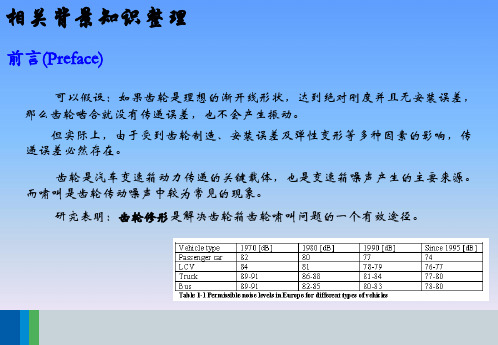
相关背景知识整理
齿向修形(Tooth Trace Modification )
在轮齿受载变形后偏离原始位置,为了补偿在预 定载荷作用下产生的弹性变形,所以在设计中给予准 确的螺旋线补偿量,就可以使轮齿在工作中恢复到理 论位置。
比如太阳轮系,左旋 β=7︒斜齿轮逆时针旋转 和配对大齿轮发生啮合,通过受力分析发现螺旋角将 会产生假设 0.1︒角度的偏移,通过反补偿该偏移角 度,最终将左旋度数改动为7.1 ︒ ,大家可以空间想 象一下该变形的情景。
相关背景知识整理
齿向修形(Tooth Trace Modification )
齿轮承受载荷后齿轮体和轴会发生弯曲、扭转等弹性变形,同时齿轮的制造误 差、箱体变形、轴承孔座制造误差等实际不可忽视的原因,都会引起齿轮齿向接触 不均匀,带来应力集中,降低齿轮的承载能力。
所以,各种因素产生的轴线不平度都会对齿向修形产生一定的影响,而鼓形修 形(crowning)、螺旋角修形(helical angle correction)和边缘倒棱(end relief) 是最常见的修形方式。
齿廓修形(Tooth Pro )
Arc-like pro:该种近似圆弧过渡的修形方式,圆弧线的过渡比较平缓。
相关背景知识整理
齿廓修形(Tooth Pro )
Progressive pro:渐开线修形,齿顶修型中推荐的一种方式。啮合更加平缓, 避免啮入冲击,有很多优点,但需要比较新型的磨齿机加工。
修形曲线,该系数一般 在5到20区间之间,设
相关背景知识整理
齿廓修形图
phi: Angle of dNa: Active tip diameter 工作齿形起点 dNf: Active root diameter 工作齿形终点 dSa: End of control diameter 齿顶修形的起点
(中文)KISSsoft软件基础培训 皮带轮

二. V型带传动经典案例分析
二. V型带传动经典案例分析
4 附加内容
设置张紧轮(tension pulley)
平面位置
二. V型带传动经典案例分析
5 练习
二. V型带传动经典案例分析
验算带速v
带速过高会使离心力过大,而降低带与带轮摩擦力,易打滑; 带速过低, 则在递相同功率的条件下所需有效拉力F较大, 易打滑, 要求带的根数较多。
要求带速: 5 m/s ≤ v ≤25 m/s
确定中心距a和带的基准长度Ld
当中心距较小时, 在单位时间内带绕过带轮的次数增多, 降低了 带的寿命,且带轮包角减小; 而中心距过大时, 且高速运转时易引 起带的颤动, 影响正常工作。
经分析计算:(1)取主动轮d1=112mm, 从动轮d2=560mm;(2)选择A型带,计算 得带长L=2240mm,中心距a=530.5mm;(3) 计算带数为4,小带轮包角为130°。
二. V型带传动经典案例分析
按照公式得到值后查上面表格找相近的标准值
小带轮基准直径dd1≥ddmin,并按带轮的基准直径系列取值。
二. V型带传动经典案例分析
KISSsoft里面关于工作情 况系数KA与国标里面规 定的表格基本一致,国 内工程师可以放心使用。 根据实际工况工作机工 作要求一般,属于一般 传动要求,确定该工作 情况系数为1.0。
二. V型带传动经典案例分析
2 设计需要传递的功率 一定的情况下,减小带轮的直径,会增大带 传动的有效拉力,但又导致V带根数的增加, 会使带的弯曲应力增加,因而小带轮的基准 直径就不能太小,所以依据表格内容选择小 带轮的直径为112mm。
二. V型带传动经典案例分析
1)初定中心距a0
KISSsoft教程:交叉斜齿轮
KISSsoft高级教程:交叉斜齿轮,结合金属蜗杆和塑料齿轮,考虑长齿高制设计方法1. 概述由于交叉斜齿轮系统中蜗杆和塑料齿轮的材料不同,将会导致啮合时齿厚的分布大小不一。
金属材料的杨氏弹性模量(材料在弹性变形阶段,其应力和应变成正比例关系,标志了材料的刚性,杨氏模量越大,越不容易发生形变,符合胡克定律)为210000MPa,而塑料材料则只有3000MPa。
所以,金属蜗杆的齿厚需要缩小,而增加塑料齿轮的齿厚。
通常,在实际啮合过程中,蜗杆上轮齿断裂的可能性占到20%-40%,而塑料斜齿轮占到60%-80%。
不采用齿廓修形的情况下,蜗轮和蜗杆的齿厚分布一般为,齿厚分布均衡。
法向齿厚Sn需要缩小ΔSn(Mn*0.5),从而使蜗杆的齿厚分布占到34%,蜗轮的轮齿厚度占到66%。
塑料齿轮的齿根强度因为金属蜗杆的轮齿减小而得到巨大提升,齿数也会相应增加。
同时,齿根和齿顶圆仍然保持和先前而修改齿形时的大小。
所以,DIN3960标准采用的公式为:考虑变位系数时,在分度圆上的齿厚:Sn=Mn*(α)。
齿根圆直径:df=d+2**Mn-2h fp 。
2. KISSsoft计算过程解析在KISSsoft软件模块中,打开交叉斜齿轮模块,如图1所示。
图1 交叉斜齿轮模块将已知数据输入到基本界面,如图2、图3和图4所示。
图2 交叉斜齿轮基本数据输入模块图3 塑料齿轮长齿制齿廓设置图4 公差界面设置点击计算按钮,会出现下面错误,如图5所示:公差设置依据资料 ②请注意:在选项框中会提示怎样解决该错误的方法。
塑料齿轮计算采用DIN3990或ISO6336,需要在“特殊模块设置”窗口中点击“塑料”栏后,激活选项“允许根据DIN3990/ISO6336简单计算塑料齿轮类型”。
② ① ①塑料齿轮不适用于DIN3990或ISO6336标准。
KISSsoft软件中,为准确计算该类型系统,需要考虑塑料的S-N 曲线,其温度依靠VDI2545标准确定。
- 1、下载文档前请自行甄别文档内容的完整性,平台不提供额外的编辑、内容补充、找答案等附加服务。
- 2、"仅部分预览"的文档,不可在线预览部分如存在完整性等问题,可反馈申请退款(可完整预览的文档不适用该条件!)。
- 3、如文档侵犯您的权益,请联系客服反馈,我们会尽快为您处理(人工客服工作时间:9:00-18:30)。
一、前言 ................................................................................................................................................................................................. 4 二、行星轮计算模块 .......................................................................................................................................................................... 4 (1)现成案例设计数据列举 .......................................................................................................................................................... 5 (2)参数在软件界面中的输入 ..................................................................................................................................................... 5 (3)现有案例基础上的优化.......................................................................................................................................................9 设计专家--粗细选型.............................................................................................................................................................9 三、行星轮轴销的建模和分析 ..................................................................................................................................................... 16 (1)实际案例数据列举 ............................................................................................................................................................... 16 (2)建模及相关软件操作技巧介绍 ....................................................................................................................................... 17 (3)分析结果解析 ........................................................................................................................................................................ 20 (一)轴承寿命计算...................................................................................................................................................................... 20 (二)轴承刚度对轴弯曲变形的影响 ..................................................................................................................................... 20 (三)轴承内部滚子应力分布 ................................................................................................................................................... 21 (四)国产轴承在软件数据库中的自定义 ............................................................................................................................ 22 (五)基本额定动载荷 C 和基本额定静载荷 C0 的计算 ................................................................................................. 23 (六)齿向修形方案的推荐........................................................................................................................................................ 25 四、轴承载荷谱计算 ........................................................................................................................................................................ 28 1.0 案例详细数据 ............................................................................................................................................................................ 29 2.0 任务要求 ..................................................................................................................................................................................... 29 3.0 建模过程 ..................................................................................................................................................................................... 30 1. 轴端几何建模 ..................................................................................................................................................................... 30 2. 轴承的添加 .......................................................................................................................................................................... 31 3. 概念齿轮副的设置 ............................................................................................................................................................ 31 4. 概念联轴器或发动机 ........................................................................................................................................................ 32 5. 名义转速 ............................................................................................................................................................................... 32 6. 载荷谱 .................................................................................................................................................................................... 33 7. 其它选项 ............................................................................................................................................................................... 34 4.0 轴承寿命结果显示 .................................................................................................................................................................. 35 1. 三档位工况 .......................................................................................................................................................................... 35 2. 三档位工况的切换 .............................................................................................................................. 36 3. 载荷谱计算 .......................................................................................................................................................................... 37