SAM9_Boot_Strategies
08-第8章 信令数据
目录第8章信令数据.....................................................................................................................8-18.1 背景知识.............................................................................................................................8-28.1.1 SIGTRAN协议........................................................................................................8-28.1.2 No.7信令.................................................................................................................8-48.1.3 V5接口协议.............................................................................................................8-78.1.4 DSS1信令...............................................................................................................8-88.1.5 掩码的概念..............................................................................................................8-88.2 配置M2UA数据.................................................................................................................8-98.2.1 配置概述..................................................................................................................8-98.2.2 增加内嵌式信令网关..............................................................................................8-118.2.3 增加M2UA链路....................................................................................................8-128.3 配置M3UA数据...............................................................................................................8-148.3.1 配置概述................................................................................................................8-148.3.2 增加M3UA本地实体.............................................................................................8-168.3.3 增加M3UA目的实体.............................................................................................8-178.3.4 增加M3UA附加选路业务(可选).......................................................................8-208.3.5 增加M3UA链路集.................................................................................................8-218.3.6 增加M3UA链路....................................................................................................8-238.3.7 增加M3UA路由....................................................................................................8-268.4 配置V5UA数据...............................................................................................................8-278.4.1 配置概述................................................................................................................8-278.4.2 增加内嵌式信令网关..............................................................................................8-288.4.3 增加V5UA链路集.................................................................................................8-298.4.4 增加V5UA链路.....................................................................................................8-308.5 配置IUA数据...................................................................................................................8-338.5.1 配置概述................................................................................................................8-338.5.2 增加内嵌式信令网关..............................................................................................8-348.5.3 增加IUA链路集.....................................................................................................8-358.5.4 增加IUA链路........................................................................................................8-368.6 配置MTP数据.................................................................................................................8-398.6.1 配置概述................................................................................................................8-398.6.2 增加MTP目的信令点............................................................................................8-418.6.3 增加MTP链路集...................................................................................................8-438.6.4 增加MTP链路.......................................................................................................8-448.6.5 增加MTP路由.......................................................................................................8-488.7 配置SCCP数据...............................................................................................................8-488.7.1 配置概述................................................................................................................8-488.7.2 增加SCCP远端信令点.........................................................................................8-508.7.3 增加SCCP子系统.................................................................................................8-528.7.4 增加新全局翻译码(可选)...................................................................................8-548.7.5 增加全局翻译码(可选).......................................................................................8-55 8.8 配置V5接口数据.............................................................................................................8-578.8.1 配置概述................................................................................................................8-578.8.2 增加V5接口..........................................................................................................8-598.8.3 增加V5变量(可选)...........................................................................................8-63 8.9 配置PRA链路数据..........................................................................................................8-648.9.1 配置概述................................................................................................................8-648.9.2 增加PRA链路.......................................................................................................8-66第8章信令数据本章所描述的信令数据主要包括M2UA数据、M3UA数据、V5UA数据、IUA 数据、MTP数据、SCCP数据、V5接口数据、PRA链路数据以及ISUP适配数据,配置信令数据必须在配置完硬件数据与媒体网关数据之后进行,如图8-1所示。
SAMinside教程

LC5,大家都知道,密码破解的好帮手。
并且,现在围绕Windows系统的密码破解,好像除了LC5就没有别的好东东了,难道密码破解市场就这样被LC5垄断了?就像我们都在声讨Microsoft垄断操作系统市场一样,我们是不是也该声讨一下LC5?在操作系统市场上,Linux横空出世给了Windows当头一棒;在Windows系统密码破解领域,SAMInside给了LC5当头一棒!下面我们就来看看Windows系统密码的破解利器——SAMInside!(图1)看到了?这就是SAMInside的界面,很简洁吧?但是不要小看SAMInside,它破解密码的速度可一点也不含糊,针对Windows NT/2000/XP/2003的用户口令,据称速度可以达到每秒几百万!很强悍吧!并且这款只有185K的软件还支持8国的语言!不过很可惜,居然没有Chinese!不过不要郁闷,虽然本文是用英文的界面进行讲解的,但是软件包内游侠已经花了一个小时做了汉化,只要从View-Language选择游侠汉化版就OK了!还有,软件还支持暴力破解、模糊破解、字典攻击、多台电脑分布式破解等多种破解方式!相比LC5,SAMInside小小的185K的身躯是不是很强大?对了,还有一个需要说明:去年我在X档案第9期有一篇加密系统密码的文章《用Syskey保护Windows密码》,而在SAMInside面前,即使用Syskey加密过的密码依然可以破解!这也是SAMInside在说明书中引以为自豪的:“SAMInsid e is the first program in the world what breaks t he Syskey protection!”——SAMInside是世界上第一个可以破解Syskey保护的程序!下面的数据来自SAMInside的帮助文件:ProcessorForcing speed on LMHashForcing speed on NTHashIntel Pentium-III 1000 MHz~3,2 million passwords/sec~3,3 million passwords/secAMD AthlonXP 1700+ (1466 MHz)~5,7 million passwords/sec~5,1 million passwords/secIntel Pentium-4 2500 MHz~3,7 million passwords/sec~5,4 million passwords/sec下面我们开始我们的Cracker之旅!菜单只有“File”、“View”和“?”三项。
SAM9263底层驱动代码

#include <linux/types.h>#include <linux/init.h>#include <linux/mm.h>#include <linux/module.h>#include <linux/platform_device.h>#include <linux/spi/spi.h>#include <linux/spi/ads7846.h>#include <linux/i2c/at24.h>#include <linux/fb.h>#include <linux/gpio_keys.h>#include <linux/input.h>#include <linux/leds.h>#include <video/atmel_lcdc.h>#include <asm/setup.h>#include <asm/mach-types.h>#include <asm/irq.h>#include <asm/mach/arch.h>#include <asm/mach/map.h>#include <asm/mach/irq.h>#include <mach/hardware.h>#include <mach/board.h>#include <mach/gpio.h>#include <mach/at91sam9_smc.h>#include <mach/at91_shdwc.h>#include "sam9_smc.h"#include "generic.h"//#define AT91SAM9263S#undef AT91SAM9263S //AT91SAM9263Kstatic void __init ek_map_io(void){/* Initialize processor: 18.432 MHz crystal demo board is 16.367 MHZ*/ at91sam9263_initialize(18432000);/* DGBU on ttyS0. (Rx & Tx only) */at91_register_uart(0, 0, 0);/* USART0 com1 on ttyS1. (Rx, Tx, RTS, CTS) */at91_register_uart(AT91SAM9263_ID_US0, 1, ATMEL_UART_CTS | ATMEL_UART_RTS);/* USART1 com2 on ttyS2. (Rx, Tx) */at91_register_uart(AT91SAM9263_ID_US1, 2,0);/* USART2 com3 on ttyS3. (Rx, Tx) */at91_register_uart(AT91SAM9263_ID_US2, 3,0);/* set serial console to ttyS0 (ie, DBGU) */at91_set_serial_console(0);}static void __init ek_init_irq(void){at91sam9263_init_interrupts(NULL);}/** USB Host port*/static struct at91_usbh_data __initdata ek_usbh_data = {.ports = 2,//.vbus_pin = { AT91_PIN_PA24, AT91_PIN_PA21 },};/** USB Device port*/static struct at91_udc_data __initdata ek_udc_data = {.vbus_pin = AT91_PIN_PA25,.pullup_pin = 0, /* pull-up driven by UDC */};/** ADS7846 Touchscreen*/#if defined(CONFIG_TOUCHSCREEN_ADS7846) || defined(CONFIG_TOUCHSCREEN_ADS7846_MODULE)static int ads7843_pendown_state(void){return !at91_get_gpio_value(AT91_PIN_PA15); /* Touchscreen PENIRQ */}static struct ads7846_platform_data ads_info = {.model = 7843,.x_min = 150,.x_max = 3830,.y_min = 190,.y_max = 3830,.vref_delay_usecs = 100,.x_plate_ohms = 450,.y_plate_ohms = 250,.pressure_max = 15000,.debounce_max = 1,.debounce_rep = 0,.debounce_tol = (~0),.get_pendown_state = ads7843_pendown_state,};static void __init ek_add_device_ts(void){at91_set_B_periph(AT91_PIN_PA15, 1); /* External IRQ1, with pullup */at91_set_gpio_input(AT91_PIN_PA31, 1); /* Touchscreen BUSY signal */}#elsestatic void __init ek_add_device_ts(void) {}#endif/** SPI devices.*/static struct spi_board_info ek_spi_devices[] = {#if defined(CONFIG_MTD_AT91_DATAFLASH_CARD){ /* DataFlash card */.modalias = "mtd_dataflash",.chip_select = 0,.max_speed_hz = 15 * 1000 * 1000,.bus_num = 0,},#endif#if defined(CONFIG_TOUCHSCREEN_ADS7846) || defined(CONFIG_TOUCHSCREEN_ADS7846_MODULE){.modalias = "ads7846",.chip_select = 3,.max_speed_hz = 125000 * 16, /* max sample rate * clocks per sample */.bus_num = 0,.platform_data = &ads_info,.irq = AT91SAM9263_ID_IRQ1,},#endif#if defined(AT91SAM9263S){ /* spidev */.modalias = "spidev",.chip_select = 0,.max_speed_hz = 10 * 1000 * 1000,.bus_num = 1,.mode = SPI_MODE_1,},{ /* spidev */.modalias = "spidev",.chip_select = 1,.max_speed_hz = 10 * 1000 * 1000,.bus_num = 1,.mode = SPI_MODE_1,},{ /* spidev */.modalias = "spidev",.chip_select = 2,.max_speed_hz = 10 * 1000 * 1000,.bus_num = 1,.mode = SPI_MODE_1,},{ /* spidev */.modalias = "spidev",.chip_select = 3,.max_speed_hz = 10 * 1000 * 1000,.bus_num = 1,.mode = SPI_MODE_1,},#endif // AT91SAM9263S};/** MCI (SD/MMC)*/static struct at91_mmc_data __initdata ek_mmc_data = { .wire4 = 1,#if defined(AT91SAM9263S).det_pin = AT91_PIN_PE16,.wp_pin = AT91_PIN_PE17,#else.det_pin = AT91_PIN_PE18,.wp_pin = AT91_PIN_PE19,#endif// .vcc_pin = ... not connected};/** MACB Ethernet device*/static struct at91_eth_data __initdata ek_macb_data = {.phy_irq_pin = AT91_PIN_PE31,.is_rmii = 1,};/** NAND flash*/static struct mtd_partition __initdata ek_nand_partition[] = {{.name = "Bootloader",.offset = 0,.size = 4*1024*1024,},{.name = "Kernel",.offset = 4*1024*1024,.size = MTDPART_SIZ_FULL,},{.name = "Ramdisk",.offset = 8*1024*1024,.size = 24*1024*1024,},{.name = "jffs2",.offset = 32*1024*1024,.size = MTDPART_SIZ_FULL,},};static struct mtd_partition * __init nand_partitions(int size, int *num_partitions) {*num_partitions = ARRAY_SIZE(ek_nand_partition);return ek_nand_partition;}static struct atmel_nand_data __initdata ek_nand_data = {.ale = 21,.cle = 22,// .det_pin = ... not connected.rdy_pin = AT91_PIN_PA22,.enable_pin = AT91_PIN_PD15,.partition_info = nand_partitions,#if defined(CONFIG_MTD_NAND_ATMEL_BUSWIDTH_16).bus_width_16 = 1,#else.bus_width_16 = 0,#endif};static struct sam9_smc_config __initdata ek_nand_smc_config = {.ncs_read_setup = 0,.nrd_setup = 1,.ncs_write_setup = 0,.nwe_setup = 1,.ncs_read_pulse = 3,.nrd_pulse = 3,.ncs_write_pulse = 3,.nwe_pulse = 3,.read_cycle = 5,.write_cycle = 5,.mode = AT91_SMC_READMODE | AT91_SMC_WRITEMODE | AT91_SMC_EXNWMODE_DISABLE,.tdf_cycles = 2,};static void __init ek_add_device_nand(void){/* setup bus-width (8 or 16) */if (ek_nand_data.bus_width_16)ek_nand_smc_config.mode |= AT91_SMC_DBW_16;elseek_nand_smc_config.mode |= AT91_SMC_DBW_8;/* configure chip-select 3 (NAND) */sam9_smc_configure(3, &ek_nand_smc_config);at91_add_device_nand(&ek_nand_data);}/** I2C devices*/static struct at24_platform_data at24c512 = {.byte_len = SZ_512K / 8,.page_size = 128,.flags = AT24_FLAG_ADDR16,};static struct i2c_board_info __initdata ek_i2c_devices[] = {{I2C_BOARD_INFO("24c512", 0x50),.platform_data = &at24c512,},/* more devices can be added using expansion connectors */};/** LCD Controller*/#if defined(CONFIG_FB_ATMEL) || defined(CONFIG_FB_ATMEL_MODULE)#if defined(CONFIG_FB_AT91_LCD480X272)static struct fb_videomode at91_tft_vga_modes[] = {{.name = "LCD480X272 @ 60",.refresh = 60,.xres = 480, .yres = 272,.pixclock = KHZ2PICOS(9000),.left_margin = 10, .right_margin = 10,.upper_margin = 6, .lower_margin = 30,.hsync_len = 96, .vsync_len = 2,.sync = FB_SYNC_HOR_HIGH_ACT | FB_SYNC_VERT_HIGH_ACT,.vmode = FB_VMODE_NONINTERLACED,},};#elif defined(CONFIG_FB_AT91_LCD640X480)static struct fb_videomode at91_tft_vga_modes[] = {{.name = "LCD640X480 @ 60",.refresh = 60,.xres = 640, .yres = 480,.pixclock = KHZ2PICOS(25000),.left_margin = 30, .right_margin = 16,.upper_margin = 32, .lower_margin = 10,.hsync_len = 96, .vsync_len = 2,.sync = FB_SYNC_HOR_HIGH_ACT | FB_SYNC_VERT_HIGH_ACT,.vmode = FB_VMODE_NONINTERLACED,},};#elif defined(CONFIG_FB_AT91_LCD800X480)static struct fb_videomode at91_tft_vga_modes[] = {{.name = "LCD800X480 @ 60",.refresh = 60,.xres = 800, .yres = 480,.pixclock = KHZ2PICOS(33000),.left_margin = 48, .right_margin = 40,.upper_margin = 3, .lower_margin = 29,.hsync_len = 128, .vsync_len = 3,.sync = FB_SYNC_HOR_HIGH_ACT | FB_SYNC_VERT_HIGH_ACT,.vmode = FB_VMODE_NONINTERLACED,},};#elif defined(CONFIG_FB_AT91_LCD800X600)static struct fb_videomode at91_tft_vga_modes[] = {{.name = "LCD800X600 @ 60",.refresh = 60,.xres = 800, .yres = 600,.pixclock = KHZ2PICOS(40000),.left_margin = 182, .right_margin = 30,.upper_margin = 25, .lower_margin = 1,.hsync_len = 64, .vsync_len = 4,.sync = FB_SYNC_HOR_HIGH_ACT | FB_SYNC_VERT_HIGH_ACT,.vmode = FB_VMODE_NONINTERLACED,},};#elif defined(CONFIG_FB_AT91_LCD1024X768)static struct fb_videomode at91_tft_vga_modes[] = {{.name = "LCD1024X768 @ 60",.refresh = 60,.xres = 1024, .yres = 768,.pixclock = KHZ2PICOS(48000),.left_margin = 80, .right_margin = 24,.upper_margin = 29, .lower_margin = 3,.hsync_len = 32, .vsync_len = 6,.sync = FB_SYNC_HOR_HIGH_ACT | FB_SYNC_VERT_HIGH_ACT,.vmode = FB_VMODE_NONINTERLACED,},};#elif defined(CONFIG_FB_AT91_LCD240X320)static struct fb_videomode at91_tft_vga_modes[] = {{.name = "LCD240X320 @ 60",.refresh = 60,.xres = 240, .yres = 320,.pixclock = KHZ2PICOS(4965),.left_margin = 1, .right_margin = 33,.upper_margin = 1, .lower_margin = 0,.hsync_len = 5, .vsync_len = 1,.sync = FB_SYNC_HOR_HIGH_ACT | FB_SYNC_VERT_HIGH_ACT,.vmode = FB_VMODE_NONINTERLACED,},};#endifstatic struct fb_monspecs at91fb_default_monspecs = {.manufacturer = "QIY",.monitor = "TFT",.modedb = at91_tft_vga_modes,.modedb_len = ARRAY_SIZE(at91_tft_vga_modes),.hfmin = 15000,.hfmax = 64000,.vfmin = 50,.vfmax = 150,};#define AT91SAM9263_DEFAULT_LCDCON2 (ATMEL_LCDC_MEMOR_LITTLE \| ATMEL_LCDC_DISTYPE_TFT \| ATMEL_LCDC_CLKMOD_ALWAYSACTIVE)static void at91_lcdc_power_control(int on){at91_set_gpio_value(AT91_PIN_PA30, on);}/* Driver datas */static struct atmel_lcdfb_info __initdata ek_lcdc_data = {.lcdcon_is_backlight = true,.default_bpp = 16,.default_dmacon = ATMEL_LCDC_DMAEN,.default_lcdcon2 = AT91SAM9263_DEFAULT_LCDCON2,.default_monspecs = &at91fb_default_monspecs,.atmel_lcdfb_power_control = at91_lcdc_power_control,.guard_time = 1,#if defined(AT91SAM9263S).lcd_wiring_mode = ATMEL_LCDC_WIRING_RGB, //yxx#endif};#elsestatic struct atmel_lcdfb_info __initdata ek_lcdc_data;#endif/** GPIO Buttons*/#if defined(CONFIG_KEYBOARD_GPIO) || defined(CONFIG_KEYBOARD_GPIO_MODULE) static struct gpio_keys_button ek_buttons[] = {{ /* BP1, "leftclic" */.code = BTN_LEFT,.gpio = AT91_PIN_PC5,.active_low = 1,.desc = "left_click",.wakeup = 1,},{ /* BP2, "rightclic" */.code = BTN_RIGHT,.gpio = AT91_PIN_PC4,.active_low = 1,.desc = "right_click",.wakeup = 1,}};static struct gpio_keys_platform_data ek_button_data = { .buttons = ek_buttons,.nbuttons = ARRAY_SIZE(ek_buttons),};static struct platform_device ek_button_device = {.name = "gpio-keys",.id = -1,.num_resources = 0,.dev = {.platform_data = &ek_button_data,}};static void __init ek_add_device_buttons(void){at91_set_GPIO_periph(AT91_PIN_PC5, 1); /* left button */ at91_set_deglitch(AT91_PIN_PC5, 1);at91_set_GPIO_periph(AT91_PIN_PC4, 1); /* right button */ at91_set_deglitch(AT91_PIN_PC4, 1);platform_device_register(&ek_button_device);}#elsestatic void __init ek_add_device_buttons(void) {}#endif/** AC97* reset_pin is not connected: NRST*/static struct ac97c_platform_data ek_ac97_data = {.reset_pin = AT91_PIN_PA13,};/** Compact Flash (via Expansion Connector) or IDE*/static struct at91_cf_data __initdata ek_cf_data = {.irq_pin = AT91_PIN_PD4,.flags = AT91_CF_TRUE_IDE, //0x01 IDE & CF// .flags = AT91_IDE_SWAP_A0_A2 , //0x02 CF// .det_pin = ... user defined// .vcc_pin = ... user defined// .rst_pin = ... user defined.chipselect = 4,};/** LEDs ... these could all be PWM-driven, for variable brightness*/static struct gpio_led ek_leds[] = {{ /* "right" led, green, userled2 (could be driven by pwm2) */ .name = "ds2",.gpio = AT91_PIN_PC29,.active_low = 1,.default_trigger = "nand-disk",},{ /* "power" led, yellow (could be driven by pwm0) */ .name = "ds3",.gpio = AT91_PIN_PB7,.default_trigger = "heartbeat",}};/** PWM Leds*/static struct gpio_led ek_pwm_led[] = {/* For now only DS1 is PWM-driven (by pwm1) */{.name = "ds1",.gpio = 1, /* is PWM channel number */.active_low = 1,.default_trigger = "none",}};/** PIO*/static struct at91_pio_data __initdata ek_pio_data = {.pio_num = 18,.pio_dir = 0x0000,.pio_pin = {AT91_PIN_PE0, AT91_PIN_PE1, AT91_PIN_PE2, AT91_PIN_PE3,AT91_PIN_PE4, AT91_PIN_PE5, AT91_PIN_PE6, AT91_PIN_PE7,AT91_PIN_PE8, AT91_PIN_PE9, AT91_PIN_PE10, AT91_PIN_PE11,AT91_PIN_PE12, AT91_PIN_PE13, AT91_PIN_PE14, AT91_PIN_PE15,AT91_PIN_PA23, AT91_PIN_PA24,}};/** TCB*/static struct at91_tcb_data __initdata ek_tcb_data = {.tc_type = {AT91_TC_CAPTURE, AT91_TC_TIMER, AT91_TC_TIMER},};/** PWM 4pins pwm0 pwm1 pwm2 pwm3*/static struct at91_pwm_data __initdata ek_pwm_data = {.pwm_enable = {1, 1, 1,1},#if defined(AT91SAM9263S).pwm_pin = { AT91_PIN_PB7, AT91_PIN_PB8, AT91_PIN_PC29 ,AT91_PIN_PB29}, #else.pwm_pin = {AT91_PIN_PB7,AT91_PIN_PB8,AT91_PIN_PB27,AT91_PIN_PB29}, #endif};/** CAN*///static void sam9263ek_transceiver_switch(int on)//{// if (on) {// at91_set_gpio_output(AT91_PIN_PA18, 1); /* CANRXEN */ // at91_set_gpio_output(AT91_PIN_PA19, 0); /* CANRS */ // } else {// at91_set_gpio_output(AT91_PIN_PA18, 0); /* CANRXEN */ // at91_set_gpio_output(AT91_PIN_PA19, 1); /* CANRS */ // }//}////static struct at91_can_data ek_can_data = {// .transceiver_switch = sam9263ek_transceiver_switch,//};///**BUZZER*/static struct at91_bzr_data __initdata ek_bzr_data = {.bzr_pin = AT91_PIN_PA12,};#if defined(CONFIG_AT91_BUZZER)static struct at91_bzr_data bzr_data;static struct resource bzr_resources[] = {[0] = {.start = AT91SAM9263_ID_PIOA,.end = AT91SAM9263_ID_PIOA,.flags = IORESOURCE_IO,},};static struct platform_device at91sam9263_bzr_device = {.name = "at91_bzr",.id = -1,.dev = {.platform_data = &bzr_data,},.resource = bzr_resources,.num_resources = ARRAY_SIZE(bzr_resources),};void __init at91_add_device_bzr(struct at91_bzr_data *data){//bzr_data = *data;bzr_data.bzr_pin = AT91_PIN_PA12;platform_device_register(&at91sam9263_bzr_device);}#elsevoid __init at91_add_device_bzr(struct at91_bzr_data *data){}#endif//#if defined(CONFIG_AT91_EBI0)#if defined(CONFIG_AT91_PC104)//Config EBI0 CS2static struct resource ebi02_resource[] = {[0] = {.start = AT91_CHIPSELECT_2,.end = AT91_CHIPSELECT_2 + 0x100000,.flags = IORESOURCE_MEM},};static struct platform_device ebi02_device = {.name = "at91_ebi02",.id = 0,.resource = ebi02_resource,.num_resources = ARRAY_SIZE(ebi02_resource),};static void __init ek_add_device_ebi02(void){/*^M* Configure Chip-Select 2 on SMC.^M* Note: These timings were calculated for MASTER_CLOCK = 100000000^M*/at91_set_A_periph(AT91_PIN_PD11, 1);at91_sys_write(AT91_SMC_SETUP(2), AT91_SMC_NWESETUP_(2) | AT91_SMC_NCS_WRSETUP_(0) | AT91_SMC_NRDSETUP_(2) | AT91_SMC_NCS_RDSETUP_(0));at91_sys_write(AT91_SMC_PULSE(2), AT91_SMC_NWEPULSE_(4) | AT91_SMC_NCS_WRPULSE_(8) | AT91_SMC_NRDPULSE_(4) | AT91_SMC_NCS_RDPULSE_(8));at91_sys_write(AT91_SMC_CYCLE(2), AT91_SMC_NWECYCLE_(16) | AT91_SMC_NRDCYCLE_(16));at91_sys_write(AT91_SMC_MODE(2), AT91_SMC_READMODE | AT91_SMC_WRITEMODE | AT91_SMC_EXNWMODE_DISABLE | AT91_SMC_BAT_WRITE | AT91_SMC_DBW_16 | AT91_SMC_TDF_(1));platform_device_register(&ebi02_device);}#elsestatic void __init ek_add_device_ebi02(void) {}#endif /* CONFIG_AT91_EBI0 */#if defined (CONFIG_AT91_EBI1)//Config EBI1 CS0static struct resource ebi10_resource[] = {[0] = {.start = 0x70000000,.end = 0x70000000 + 0x400000,.flags = IORESOURCE_MEM},};static struct platform_device ebi10_device = {.name = "at91_ebi10",.id = 0,.resource = ebi10_resource,.num_resources = ARRAY_SIZE(ebi10_resource),};static void __init ek_add_device_ebi10(void){/*^M* Configure Chip-Select 2 on SMC.^M* Note: These timings were calculated for MASTER_CLOCK = 100000000^M*/at91_sys_write(AT91_SMC1_SETUP(0), AT91_SMC_NWESETUP_(4) | AT91_SMC_NCS_WRSETUP_(2) | AT91_SMC_NRDSETUP_(4) | AT91_SMC_NCS_RDSETUP_(2));at91_sys_write(AT91_SMC1_PULSE(0), AT91_SMC_NWEPULSE_(8) | AT91_SMC_NCS_WRPULSE_(16) | AT91_SMC_NRDPULSE_(8) | AT91_SMC_NCS_RDPULSE_(16));at91_sys_write(AT91_SMC1_CYCLE(0), AT91_SMC_NWECYCLE_(32) | AT91_SMC_NRDCYCLE_(32));at91_sys_write(AT91_SMC1_MODE(0), AT91_SMC_READMODE | AT91_SMC_WRITEMODE | AT91_SMC_EXNWMODE_DISABLE | AT91_SMC_BAT_WRITE | AT91_SMC_DBW_16 | AT91_SMC_TDF_(16));platform_device_register(&ebi10_device);}#elsestatic void __init ek_add_device_ebi10(void) {}#endif /* CONFIG_AT91_EBI1 *//********************************************************************/ static void __init ek_board_init(void){/* Serial */at91_add_device_serial();/* USB Host */at91_add_device_usbh(&ek_usbh_data);/* USB Device */at91_add_device_udc(&ek_udc_data);/* SPI */at91_set_gpio_output(AT91_PIN_PE20, 1); /* select spi0 clock */at91_add_device_spi(ek_spi_devices, ARRAY_SIZE(ek_spi_devices));/* Touchscreen */ek_add_device_ts();/* MMC */at91_add_device_mmc(1, &ek_mmc_data);/* Ethernet */at91_add_device_eth(&ek_macb_data);/* NAND */ek_add_device_nand();/* I2C */at91_add_device_i2c(ek_i2c_devices, ARRAY_SIZE(ek_i2c_devices));/* LCD Controller */at91_add_device_lcdc(&ek_lcdc_data);/* Push Buttons */ek_add_device_buttons();/* AC97 */at91_add_device_ac97(&ek_ac97_data);/**************************************//* Compact Flash or IDE */at91_add_device_cf(&ek_cf_data);/*gpio*/at91_add_device_pio(&ek_pio_data);/*BUZZER*/at91_add_device_bzr(&at91sam9263_bzr_device);/* tcb */#if defined(AT91SAM9263S)at91_add_device_tc(&ek_tcb_data);#endif/* pwm */at91_add_device_pwm(&ek_pwm_data);/* ebi2 */ek_add_device_ebi02();/* ebi5 */ek_add_device_ebi10();/* can */// at91_add_device_can(&ek_can_data);/**************************************//* LEDs */at91_gpio_leds(ek_leds, ARRAY_SIZE(ek_leds));at91_pwm_leds(ek_pwm_led, ARRAY_SIZE(ek_pwm_led));/* shutdown controller, wakeup button (5 msec low) */at91_sys_write(AT91_SHDW_MR, AT91_SHDW_CPTWK0_(10) | AT91_SHDW_WKMODE0_LOW| AT91_SHDW_RTTWKEN);}MACHINE_START(AT91SAM9263EK, "QY AT91SAM9263-EK")/* Maintainer: Atmel */.phys_io = AT91_BASE_SYS,.io_pg_offst = (AT91_VA_BASE_SYS >> 18) & 0xfffc,.boot_params = AT91_SDRAM_BASE + 0x100,.timer = &at91sam926x_timer,.map_io = ek_map_io,.init_irq = ek_init_irq,.init_machine = ek_board_init,MACHINE_END。
AT91SAM9G15 9G25 9G35 9X25 9X35 ARM 嵌入式评估板用户手册 V1.

MBS-SAM9G15/9G25 /9G35/9X25/9X35 User ManualRelease:V1.0 Date:2012.04.17Embest Info&Tech Co.,LTD.Revision historyRev Date Description by1.0 20120417 Initial version huangyin Note:This user guide introduces the ARM embedded evaluation board produced by Embest , based on A TMEL ARM926 -EJ-S-based processors as listed below:A T91SAM9G15A T91SAM9G25A T91SAM9G35A T91SAM9X25A T91SAM9X35The user guide pertains to the following kit references:MBS-SAM9G15MBS-SAM9G25MBS-SAM9G35MBS-SAM9X25MBS-SAM9X35The user guide gives design information on the kit and is made up of 4 sections:Section 1 includes a photo of the board, deliverables and applicable documents.Section 2 describes the hardware resource of the board.Section 3 describes the updating software list of the board.Section 4 provides the ways to contact us.This document copyright belongs to embest technology Co., LTD. © 2012In the passage , 9X5 serial general means 9G15,9G25,9G35,9X25,9X35.Section 1_Scope1.1 IntroductionThe MBS-SAM9X5 Series development board, which consists of two parts of the MBC-SAM9X5 core board and MBM-SAM9X5_9M10 main board, is the Embest launched based on the development board the A TMEL A T91SAM9X5. The core board is the smallest-sized 9X5 core board to help you as much as possible to reduce the product space, you can take advantage of the core board to complete product development easily and improve time to hit the market. Using industrial-grade connectors can achieve seamless connection with the custom main board, greatly improving the stability of the product.MBS-SAM9X5 SBC clocked up to 400MHz, the development board that supportsLinux-2.6.39 operating system debugging, angstrom, and the android-2.3.5_r1 file system test. With 256MB NandFlash, 128MB of DDR II, 4MB serial dataflash, 64KBserial eeprom, and a rich feature set expansion: high-speed USB 2.0 (480MHz), audio input, audio output, 10/100Mbps network, the JTAG debug interface, DBGU serial Micro SD card slot, SD/MMC card interface, CMOS camera interface, support for video data acquisition.1.2 Scope1.3 DeliverablesNO Items Qty Description Inspection1 MBS-SAM9X5 board 1 MBC + MBM SC2 Power Adapter (5V, 1.25A rating) 1 5V, 1.25A SC3 Micro USB Cable 1 Micro USB SC4 10/100 Ethernet Cable 1 Cross-over cable SC5 DB9-IDC10 Cable 1 Serial cable SC7 TFT LCD Panel 1 LCD with touch(4'', 7'')SCSection 2_Hardware2.1 Available resource for 9x5projects 9G15 9G25 9G35 9X25 9X35MPUs AT91SAM9G15/9G25/9G35/9X25/9X35(ARM926EJ-Score frequency400MHz) learn more <<memory 128MB SDRAMFlash256MB nandflash; 4MB serial dataflash;EEPROM64KB serial eeprom;256B 1-wire eeprom *2 (MBC+MBM)USBUSB HOST 2 2 2 2 2USB OTG 1 1 1 1 1 AudioAudio in 1 1 1 1 1Audio out 1 1 1 1 1 NET ETH 0 1 1 2 1 Camera Camera 0 1 0 0 0 UartUART interface 1 1 1 1 1USART interface 1 2 1 2 1 JTAG JTAG 1 1 1 1 1 RS485 RS485 2 2 2 2 2 CAN CAN 0 0 0 2 2 SD cardMicroSD 1 1 1 1 1SDCard 1 1 1 1 1 telephone telephone 1 1 1 1 1 LCD 4.3,7.0inch LCD 1 0 1 0 1button User button*2;Q touch button*41 1 1 1 1RTC Back up battery 1 1 1 1 1 Extended 30*2pin interface 1 1 1 1 1power 5V supply 1 1 1 1 1 2.2 Core Board2.2.1 ScopeFigure 2-1 core board frontFigure 2-2 core board back2.2.2 Structure2.2.3 Core board resourcesProcessor SAM9X5(SAM9G15/9G25/9G35/9X25/9X35)12MHz32.768MHz128MB DDR2 memory256MB nandflash memory with chip selection control switch4MB SPI Serial dataflash with chip selection control switch64KB EEPROM256B 1-wire EEPROMOn-board power regulationTwo user LEDsOptional PHYSDIOIMM200 card edge interface2.3 Function blocks for MBC-SAM9G15Here we make description about function blocks of the board with some parts of the schematic. For the whole schematic please refer to MBC-SAM9X5_REVB(embest).pdf and MBM_SAM9X5_9M10_RevA(embest).pdf (direct:)2.3.1 processorSAM9G15---ARM926EJ-S™ ARM® Thumb® Processor running at up to 400 MHz, System running at up to 133 MHz For more information about processor ATSAM9G15, please refer to SAM9G15 Complete.pdf or SAM9G15 Summary.pdf ()2.3.2 clock circuitryCrystal for internal clock, 12MHzCrystal for RTC clock, 32.768KHzCrystal for Ethernet clock RMII,50MHz2.3.4 Power supplies2.3.5 MemoryThe device serial processor features a DDR/SDR memory interface and an External Bus Interface to enable interfacing to a wide range of external memories and to almost any kind of parallel peripheral.The EBI is connected to two kinds of memory device:128MB DDR SDRAM256MB nandflash2.3.6 Dataflash(SPI controller)The serial processor provides two high-speed serial peripheral interface (SPI) controllers. One port is used to interface with the on-board serial Dataflash (4MB serial dateflash).2.3.7 EEPROM(TWI controller)The serial processor has a full speed(400KHz) master/slave TWI Serial Controller. The controller is mostly compatible with industry standard I2C and SMBus Interfaces. This port is used to interface with the on-board serial EEPROM,ISI, Qtouch device and audio codec interface.2.3.8 1-wire EEPROMThe board uses a 1-wire device as “firmware label”to store the information such as chip type, manufacturer’s name, production date etc.2.3.9 Optional PHYSome of the core boards (SAM9G15 not included) provide a location for a 10/100 Ethernet MAC/PHY interface. For more information about the Ethernet controller device, refer to the Dacvicom DM9161 controller manufacturer’s datasheet.2.3.10 SODIMM200 interface2.4 Main BoardThe main board is compatible with both the the 9m10 core board and 9x5 series core board.2.4.1 resourcesONE WIRE EPPROM(1024-bit);1 JTAG DEBUG interface;1 Camera interface(9m10 & 9G25);2 24-bit LCD interfaces(with touch);1 DBGU serial interface(3 wires);2 communication serial interfaces(5-wire & 3-wire);2 10/100Mb Ethernet interfaces;Note: 9m10 1; 9G15, 9G25, 9X35, 9G35 1; 9X25 22 RS485 interfaces;2 CANinterfaces;1 SmartDAA interface;2 USB 2.0 Host interfaces;Note: 9m10 1 (USB_A); 9x5 2 (USB_B & USB_C);1 USB high speed USB2.0 OTG interface;Note: 9m10(USB_B) and 9X5(USB_A) OTG interface;4 buttons (QTOUCH);2 buttons (reset, wakeup);1 Micro SD interface;1 SD card interface;3 LEDs;1 audio input and output interface;1 backup battery holder;User interface (50 GPIOs).2.4.2 Electrical CharacteristicsPower: 5V, 2A;Operating Temperature: 0~70C;Power Consumption: to be confirmed2.4.3 Mechanical and Physical CharacteristicsSize: 181x125mm;Board layer: 4;Board thickness: 6mm;Interface type: DIMM 200 Pins2.5 Function blocks for MBM-SAM9G152.5.1 Power supply2.5.2 AUDIOThe board includes a WM8731 CODEC for digital sound input and output. This interface includes audio jacks for line audio input and headphone line output.The SAM9 processor is configured in IIS slave mode to interface with the WM8731 Codec.2.5.3 Ethernet 0 interfaceEthernet 0 is available for the core board which has a optional PHY.2.5.4 Ethernet1Etherne1 is only available for SAM9X25, The PHY on Ethernet 1 is enabled by the SELCONFIG signal from a pull-down resistor on the core board.2.5.5 SD/MMC CardThe board has two high-speed Multi Media Card Interface. The first interface is used as a 4-bit interface (MCI0), connected to a MicroSD card slot. The second interface is used as a 4-bit Interface (MCI1), connected to an SD/MMCcard slot.2.5.6 1-wire EEPROM2.5.7 USB moduleThe board contains two USB HOST interfaces and an USB OTG interface.2.5.8 DBGUThe DBGU is connected to the DB-9 male socket through an RS-232 Transceiver (TXD and RXD only).2.5.9 USARTsThe USART0 and USART3 are used as serial communication ports. Both USARTs are buffered with an RS-232 Transceiver and connected to the DB-9 male socket. USART0 just own TXD and RXD signal, and USART3 equips addition handshake CTS/RTS control.The USART3 is only supported by SAM9G25 and SAM9X25 processors.USART0USART32.5.10 CANTwo boards(MBS-SAM9X35 and MBS-SAM9X25), feature two controller area network (CAN) ports with transceiver.2.5.11 RS485Two RS485 interfaces.2.5.12 JTAGSoftware debug is accessed by a standard 20-pin JTAG connection.2.5.13 Qtouch2.5.13 LCD interface 4.3 inch LCD interface7.0 inch LCD interface2.5.14 ISI Interface2.5.15 Telephone interfaceThe board features a smart DAA(DATA Access Arrangement) chip to drive an analog telephone line.2.5.16 Key2.5.17 RTC Power2.5.18 user interface2.6 Jumpers2.6.1 SW1 settingsNO. Setting 1 Nandflash enable 2 Dataflash enable2.6.2 SW2 settingsIt ’s used for matching Audio Lord the clock signal of the 9x5 core board NO. Settings 1 Do not care 2 Close 3 Open 4Close2.6.3 JP jumpersNO. settingsdefault JP1close :force powerclose JP2,JP3,JP4,JP5,JP6.JP7, close :enable RS485 terminal resistance open JP8,JP10close :enable CAN terminal resistance openJP9 close :DBGU available open : CAN availableNote: if you download image to the board throughUSB, you must close the jumperclose JP11close: enable camera interface (for 9G25)openJP12 Open: disable external flashClose: enable external flash closeJP14,JP15 1-2:RS485 for 9M10 core 2-3:RS485 for 9x5 coreSection 3_Software (updating)3.1 MDK resourcesARM9 productsprojects9G15 9G25 9G35 9x25 9x35 adc √√√√√can × × × √√dma √√√√√eeprom √√√√√Emac(eth1) × × × √×getting-started √√√√√Hsmci_multimedia_card √√√√√Hsmci_sdcard √√√√√Hsmci_sdio √√√√√LCD_4.3 √× √× √LCD_7.0 √× √× √LCD_10.2 √× √× √periph_protect √√√√√pmc_clock_switching √√√√√pwm √√√√√qtouch √√√√√Rs485_loopback √√√√√Rs485_twoport √√√√√Smc_nandflash √√√√√Spi_serialflash √√√√√Ssc_dma_audio √√√√√sysc √√√√√tc_capture_waveform √√√√√Touchscreen_4.3 √× √× √Touchscreen_7.0 √× √× √twi √√√√√Usart_serial_COM0 √√√√√Usart_serial_COM3 × √× √× Usart_hw_handshaking_COM3 × √× √× usb_audio_looprec √√√√√usb_cdc_serial √√√√√usb_core √√√√√usb_hid_keyboard √√√√√usb_hid_mouse √√√√√usb_hid_msd √√√√√usb_hid_transfer √√√√√usb_iad_cdc_cdc √√√√√usb_iad_cdc_hid √√√√√usb_iad_cdc_msd √√√√√usb_masstorage √√√√√3.2 Linux resourcesnote :(1) “√”--included, “×”-- not included; (2) Free and open CategoriesDrivers 9G159G259G359X259X359x5BootloaderAT91BootstrapLead Uboottested, free&openUboot1. NandFlash erasing ,reading and writing2.support network download images3. Support the establishment, save the environmentvariable4. Support the memory contents display, contrast,and modification5. Support bootm 、bootargs settingstested, free&openkernelnetETH0× √ √ √ √ tested, free&open ETH1 × × × √ × tested, free&open serialUSART0√ √ √ √ √ tested, free&open USART3 × √ × √ × tested, free&open DBGU √ √ √ √ √ tested, free&open CANCAN0× × × √ √ untested, providecodes CAN1 × × × √ √ untested, providecodes USBUSB_HOST*2 √ √ √ √ √ tested, free&open USB_OTG √ √ √ √ √ tested, free&open SMD 驱动√ √ √ √ √ provide hardware interface only SDcardMicroSD√ √ √ √ √ tested, free&open SDCard√ √ √ √ √ tested, free&open camera (ISI) × √ × × × untested, providecodes LCD+touch √ × √ × √ tested, free&open Zigbee√ √ √ √ √ provide hardware interface only SPI√√√√√reuse, unregistered equipmentTWI √√√√√tested, free&openQtouch √√√√√tested, free&openDMA √√√√√tested, free&openGPIO √√√√√tested, free&openAngstrom √√√√√provide file system File systemAndroid √× √× √provide file systemSection 4_Purchase and serviceIf you are interested in the board ,you may connect:Sales and marketing: **********************For Technical Support: ************************URL: /en/。
SAM 砖机的福音

原理是利用SAM可以更改ICCID以及IMEI 配合APPLE的ICCID漏洞进行解锁,支持重启,热拔。
1,首先需要IPHONE要激活,越狱。
用原卡或者红雪都可以。
安装SAM 我用的源是:,安装后,关机,插入所用的移动、联通、电信卡(不需要卡贴);这里忘记说了,中国超雪,极学,还有ultrasn0w我都是卸载下去了。
2、接着,打开“设置”-“SAM”-“Utilities”(高级),点击“Revert Lockdownd to Stock”(将设备设置为未激活状态)(或者De-Activate),OK后,返回SAM菜单,查看“More Information”,看看“Activation State”是不是回到了“Unactivated”(未激活)。
3,SAM的作者Sam Bingner 大神更新一版SAM 大大减少了操作流程,新版的SAM中在SAM菜单中有一项Hacktivate,打开Hacktivate,看看Enabled是否打开了,如果没打开,请开启,然后, 点击Method,选择By Bundle Name(运营商和其ID名字),找到你自己手机的运营商,不知道的,自己通过自己的本机信息去查询!~ 返回菜单,下面多出了两个选项,Bundle,SIM ID。
举个例子,韩版KT 的,Bundle就选择KTF_kr,SIM ID 默认第一个;美版 BUNDLE 选ATT-US ,SIM ID默认第一个(一般不用改),就可以链接itunes激活,然后进行下面的第6步骤。
重点在这里SAM中有一些运营商的IMSI是有问题的,需要自己填写的锋友请在Method选择Manual,然后回到SAM菜单手动填写查到的IMSI,就可以链接itunes激活,然后进行下面的第6步骤。
33、返回SAM菜单,看看Enabled是否打开了,如果没打开,请开启,然后,点击Method,选择By Bundle Name(运营商和其ID名字),找到你自己手机的运营商,不知道的,自己通过自己的本机信息去查询!~ 返回菜单,下面多出了两个选项,Bundle,SIM ID。
at91-看门狗驱动修改指南详解

附录一、驱动程序:at91sam9g20核心板的看门狗驱动看门狗的驱动一般来说比较简单,只要做寄存器的设置实现开启、关闭、喂狗功能。
本项目中我们使用的是at91sam920处理器,带有看门狗定时器。
这个看门狗的驱动却比较复杂,应用层想用它的话,将涉及到boot引导设置,uboot配置及驱动,改写驱动程序。
下面将逐步说明。
1、boot引导(bootstrap-v1.15)由于该看门狗的MR寄存器只能写一次(Only a processor reset resets it.),而默认情况下看门狗在boot引导程序中被关闭了,所以在boot引导程序中我们要开启看门狗。
在board/at91sam9g20ek/at91sam9g20ek.c文件的硬件初始化函数hw_init中注释掉下面的配置即可开启看门狗:/* writel(AT91C_WDTC_WDDIS, AT91C_BASE_WDTC + WDTC_WDMR); */为了功能设置:我们配置如下:writel(AT91C_WDTC_WDV | AT91C_WDTC_WDD | AT91C_WDTC_WDRSTEN | AT91C_WDTC_WDFIEN, AT91C_BASE_WDTC + WDTC_WDMR);2、uboot配置及驱动(uboot-v1.3.4):默认情况下,看门狗在uboot中没有配置,需要手动添加配置,在文件include/configs/at91sam9g20ek.h中添加如下配置#define CONFIG_HW_WA TCHDOG 1#define CONFIG_AT91SAM9_WA TCHDOG 1此时编译uboot,会提示你找不到hw_watchdog_reset复位函数,这是因为虽然我们配置看门狗,但看门狗的uboot驱动并不存在,下面就来添加uboot下的看门狗驱动。
1)添加include/asm-arm/arch-at91sam9/at91_wdt.h,内容如下/** [origin: Linux kernel arch/arm/mach-at91/include/mach/at91_wdt.h]** Copyright (C) 2008 Jean-Christophe PLAGNIOL-VILLARD <plagnioj at >* Copyright (C) 2007 Andrew Victor* Copyright (C) 2007 Atmel Corporation.** Watchdog Timer (WDT) - System peripherals regsters.* Based on AT91SAM9261 datasheet revision D.** This program is free software; you can redistribute it and/or modify* it under the terms of the GNU General Public License as published by* the Free Software Foundation; either version 2 of the License, or* (at your option) any later version.*/#ifndef AT91_WDT_H#define AT91_WDT_H#define AT91_WDT_CR (AT91_WDT + 0x00) /* Watchdog Control Register */ #define AT91_WDT_WDRSTT (1<<0) /* Restart */#define AT91_WDT_KEY (0xa5 << 24) /* KEY Password */#define AT91_WDT_MR (AT91_WDT + 0x04) /* Watchdog Mode Register */ #define AT91_WDT_WDV (0xfff << 0) /* Counter Value */#define AT91_WDT_WDFIEN (1 << 12) /* Fault Interrupt Enable */#define AT91_WDT_WDRSTEN (1 << 13) /* Reset Processor */#define AT91_WDT_WDRPROC (1 << 14) /* Timer Restart */#define AT91_WDT_WDDIS (1<< 15) /* Watchdog Disable */#define AT91_WDT_WDD (0xfff << 16) /* Delta Value */#define AT91_WDT_WDDBGHLT (1 << 28) /* Debug Halt */#define AT91_WDT_WDIDLEHLT (1 << 29) /* Idle Halt */#define AT91_WDT_SR (AT91_WDT + 0x08) /* Watchdog Status Register */#define AT91_WDT_WDUNF (1 << 0) /* Watchdog Underflow */#define AT91_WDT_WDERR (1 << 1) /* Watchdog Error */#endif2)添加drivers/watchdog/at91sam9_wdt.c,内容如下/** [origin: Linux kernel drivers/watchdog/at91sam9_wdt.c]** Watchdog driver for Atmel AT91SAM9x processors.** Copyright (C) 2008 Jean-Christophe PLAGNIOL-VILLARD <plagnioj at > * Copyright (C) 2008 Renaud CERRATO r.cerrato at til-technologies.fr** This program is free software; you can redistribute it and/or* modify it under the terms of the GNU General Public License* as published by the Free Software Foundation; either version* 2 of the License, or (at your option) any later version.*//** The Watchdog Timer Mode Register can be only written to once. If the * timeout need to be set from U-Boot, be sure that the bootstrap doesn't * write to this register. Inform Linux to it too*/#include <common.h>#include <watchdog.h>#include <asm/arch/hardware.h>#include <asm/arch/io.h>#include <asm/arch/at91_wdt.h>//#include <asm-arm/arch-at91sam9/at91_wdt.h>#define ms_to_ticks(t) (((t << 8) / 1000) - 1)#define ticks_to_ms(t) (((t + 1) * 1000) >> 8)/* Hardware timeout in seconds */#define WDT_HW_TIMEOUT 2/** Set the watchdog time interval in 1/256Hz (write-once)* Counter is 12 bit.*/static int at91_wdt_settimeout(unsigned int timeout){unsigned int reg;unsigned int mr;/* Check if disabled */mr = at91_sys_read(AT91_WDT_MR);if (mr & AT91_WDT_WDDIS){printf("sorry, watchdog is disabled/n");return -1;}/** All counting occurs at SLOW_CLOCK / 128 = 256 Hz** Since WDV is a 12-bit counter, the maximum period is* 4096 / 256 = 16 seconds.*/reg = AT91_WDT_WDRSTEN /* causes watchdog reset *//* | AT91_WDT_WDRPROC causes processor reset only */| AT91_WDT_WDDBGHLT /* disabled in debug mode */| AT91_WDT_WDD /* restart at any time */| (timeout & AT91_WDT_WDV); /* timer value */at91_sys_write(AT91_WDT_MR, reg);return 0;}void hw_watchdog_reset(void){at91_sys_write(AT91_WDT_CR,A T91_WDT_KEY | AT91_WDT_WDRSTT); }void hw_watchdog_init(void){/* 16 seconds timer, resets enabled */at91_wdt_settimeout(ms_to_ticks(WDT_HW_TIMEOUT * 1000));}3)添加drivers/watchdog/Makefile## (C) Copyright 2008# Wolfgang Denk, DENX Software Engineering, wd at denx.de.## See file CREDITS for list of people who contributed to this# project.## This program is free software; you can redistribute it and/or# modify it under the terms of the GNU General Public License as# published by the Free Software Foundation; either version 2 of# the License, or (at your option) any later version.## This program is distributed in the hope that it will be useful,# but WITHOUT ANY W ARRANTY; without even the implied warranty of# MERCHANTABILITY or FITNESS FOR A PARTICULAR PURPOSE. See the # GNU General Public License for more details.## You should have received a copy of the GNU General Public License# along with this program; if not, write to the Free Software# Foundation, Inc., 59 Temple Place, Suite 330, Boston,# MA 02111-1307 USA#include $(TOPDIR)/config.mkLIB := $(obj)libwatchdog.aCOBJS-$(CONFIG_AT91SAM9_WATCHDOG) += at91sam9_wdt.oCOBJS := $(COBJS-y)SRCS := $(COBJS:.o=.c)OBJS := $(addprefix $(obj),$(COBJS))all: $(LIB)$(LIB): $(obj).depend $(OBJS)$(AR) $(ARFLAGS) $@ $(OBJS)######################################################################### # defines $(obj).depend targetinclude $(SRCTREE)/rules.mksinclude $(obj).depend######################################################################### 4)修改uboot的Makefile,主要是把watchdog编辑到工程里修改1:LIBS += drivers/video/libvideo.a+LIBS += drivers/watchdog/libwatchdog.a(添加)LIBS += common/libcommon.a修改2:TAG_SUBDIRS += drivers/usbTAG_SUBDIRS += drivers/video+TAG_SUBDIRS += drivers/watchdog (添加)5)另外,为了在其它地方调用WA TCHDOG_RESET函数,可以将watchdog.h添加包含到include/common.h文件中:#if defined (CONFIG_HW_WATCHDOG)#include <watchdog.h>#endif6)修改串口驱动drivers/serial/atmel_usart.c,主要是在串口读的时候复位看门狗,防止系统重启int serial_getc(void){- while (!(usart3_readl(CSR) & USART3_BIT(RXRDY))) ; (删除)+ while (!(usart3_readl(CSR) & USART3_BIT(RXRDY))) (添加)+ WATCHDOG_RESET(); (添加)return usart3_readl(RHR);}3、改写驱动程序(linux2.6.30内核)1、配置内核在默认情况,系统并不加载看门狗驱动,需要配置内核:make menuconfigDevice drivers-->Watchdog Timer Support-->AT91SAM9X / A T91CAP9 watchdog 然后编译,重新烧写uImage文件到板子上。
M9问题汇总及解决方法

【新手入门之软件安装篇】*首先要说的是在Android平台上安装文件的后缀名一般为“.apk”(如果你下载的软件是rar或者zip的话请解压之后再安装),和WM平台上的安装文件的后缀名“.exe”或者S60平台上的安装文件的后缀名“.sis或.sisx”相似。
所以只要看到“.apk”结尾的文件就肯定是安装文件了。
建议在SD卡里建立几个文件夹,这样便于管理,例如:软件、游戏、插件等,然后把下载的APK文件拷到对应的文件夹下面即可,此时关闭USB,点击手机里的文档(M9的文档已经很地道了),这时就可以看到刚才在SD卡中建立的文件夹了,找到自己要安装的APK文件直接点击即可,按照提示进行安装,一般安装很快的。
软件卸载非常简单方便,直接按住要卸载的软件1秒钟,手机下方有一个红色卸载区域,把软件直接拉进去即可。
===============================================【新手入门之操作篇】M9有屏幕下方有三个操作间,从左到右分别是返回键、主页键、菜单键,主页键为物理按键,其他两个为触摸式按键。
这里给一些快捷键:截图=同时按住电源键+主页键,这里需要注意,在关机状态下按住电源键+主页键为清除数据,谨慎使用。
开机状态下,长按电源键15秒后手机自动重启,这个很有用。
有的界面里比如浏览器界面下长按菜单键会出现所浏览的所有网页。
双击主页键(要快速),可以看到最近打开的程序,可以用这个杀进程。
拒接电话可以双按电源键,按一次是静音,或者把屏幕偏上方的电话往下拉即可。
结束程序时用返回键,不要点击主页键退出,这个跟IP有区别。
*拨号界面下输入*#*#4636#*#*进入工程测试模式。
Android是一个开源的系统,这意味着它有更高的开放性。
有很多实用的数据工程师们把它们放到Android的工程测试模式里,在这里我们可以查看手机网络信息、电池温度、电池使用时间、传感器使用情况等,这里就是一片无比宽广的天地,当然初级网友最好是看看就算了,千万不要改动里面的设置。
Linux下at91sam9x25嵌软开发测试环境搭建文档
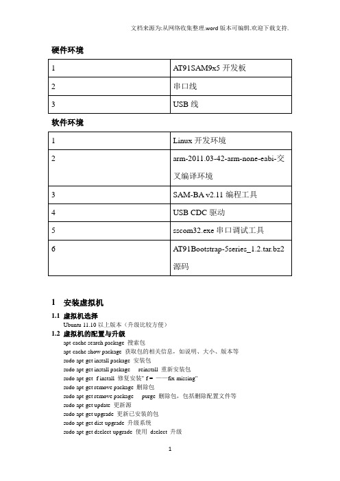
硬件环境软件环境1 安装虚拟机1.1虚拟机选择Ubuntu 11.10以上版本(升级比较方便)1.2虚拟机的配置与升级apt-cache search package 搜索包apt-cache show package 获取包的相关信息,如说明、大小、版本等sudo apt-get install package 安装包sudo apt-get install package - - reinstall 重新安装包sudo apt-get -f install 修复安装"-f = ——fix-missing"sudo apt-get remove package 删除包sudo apt-get remove package - - purge 删除包,包括删除配置文件等sudo apt-get update 更新源sudo apt-get upgrade 更新已安装的包sudo apt-get dist-upgrade 升级系统sudo apt-get dselect-upgrade 使用dselect 升级apt-cache depends package 了解使用依赖apt-cache rdepends package 是查看该包被哪些包依赖sudo apt-get build-dep package 安装相关的编译环境apt-get source package 下载该包的源代码sudo apt-get clean && sudo apt-get autoclean 清理无用的包sudo apt-get check 检查是否有损坏的依赖2 Linux下安装交叉编译环境2.1安装步骤1)下载arm-2011.03-42-arm-none-eabi-i686-pc-linux-2)命令行安装# tar xvzf arm-2011.03-42-arm-none-eabi-i686-pc-linux-# cd arm-2011.033 安装arm设备编程工具SAM Boot Assistant(SAM-BA)3.1 Windows下安装1)安装sam-ba_;2)安装USB CDC驱动;图 3.1图 3.2图 3.3图 3.4图 3.5图 3.7打开SAM-BA 2图 3.8图 3.93.2 Linux下安装1)解压sam-ba_;2)安装USB CDC驱动;1/ Login with administrator rights2/ Unload usbserial module if it is already running #rmmod usbserial3/ Load usbserial kernel module#modprobe usbserial vendor=0x03eb product=0x61244/ Verify that the USB connection is established#lsusb -d 03eb:6124Bus 004 Device 006: ID 03eb:6124 Atmel Corp5/ Know which USB connection is established#dmesgkernel: usb 4-2: new full speed USB device using uhci_hcd and address 5kernel: usb 4-2: configuration #1 chosen from 1 choicekernel: usbserial_generic 4-2:1.0: generic converter detectedkernel: usbserial_generic: probe of 4-2:1.0 failed with error -5kernel: usbserial_generic 4-2:1.1: generic converter detectedkernel: usb 4-2: generic converter now attached to ttyUSBx=> you will have to use /dev/ttyUSBx to connect to your boardRunning SAM-BA CDC Serial version :Launch 'sam-ba_cdc_ file, and select your board and the /dev/ttyUSBxdevice where your board in mounted on.- Update the kernel:# apt-get install linux-image-generic linux-headers-generic- On 64 bits version install 32 bits libraries:# apt-get install ia32-libs- Give sam-ba execute permission if needed:$ chmod +x sam-ba- Connect the board- Create a symlink on /dev/ttyACM0# ln -s /dev/ttyACM0 /dev/ttyUSB0- Launch sam-baTested on:Ubuntu 10.04 64 bits (Ubuntu 10.10 32 bits (Ubuntu 10.10 64 bits (Ubuntu 10.10 64 bits (Ubuntu 11.10 64 bits alpha3How to check if your kernel is up to date ?$ dmesgIf you have something like that (not exactly the same) it's ok:[227274.230016] usb 5-1: new full speed USB device using uhci_hcd and address 5[227274.395739] cdc_acm 5-1:1.0: This device cannot do calls on its own. It is not a modem.[227274.395768] cdc_acm 5-1:1.0: ttyACM0: USB ACM deviceIf you don't have this part: 'This device cannot do calls on its own. It is not a modem.',your kernel is probably not up to date or the cdc_acm patch has not been backported.4 示例4.1 下载AT91Bootstrap源码1)得到源码;2)解压# tar xvzf AT91Bootstrap-5series_#cd AT91Bootstrap-5series_1.24.2 配置AT91Bootstrap和选择启动媒介1) 从NAND FLASH启动#make at91sam9xnf_defconfig2)添加环境变量#vi .profilePATH="$PATH:/root/Public/arm-2011.03/bin"export PATH#souce .profile3)配置AT91Bootstrap#make menuconfig4.3 编译AT91Bootstrap#export $CROSS_COMPILE=” arm-none-eabi-”#make clear#make在../AT91Bootstrap-5series_1.2/binaries下产生at91sam9x5ek-nandflashboot- 4.4 使用AT91Bootstrap二进制文件1)从NAND flash启动A T91Bootstrap图 4.1在NAND和SPI无效的前提下,启动SAM-BA,烧AT91Bootstrap到NAND flash,如图4.1所示:(1)在SAM-BA图形用户界面上选择NandFlash媒介选项卡;(2)1)在NAND有效的前提下,在Scripts下拉列表框中选择“Enable NandFlash”;然后点击“Execute”按钮,完成NandFlash的初始化,如图4.2所示;图 4.2.12)清除芯片上原来烧的信息图 4.2.2结果如图 4.5所示。
V59_Sboot_PM Setting

Sboot Setting1.Sboot概述:(1)主要作用: 用于修改GPIO、MIU的参数{ PHASE、ODT、CLOCK等}2.如何编译:编译环境: coLinux(1).进入sboot目录:(2)配置config信息: make menuconfig指令进入配置页面.(3)配置页面分别选择如下:[1] Mstar Chip Family <Select> Macaw12[2] Board Selection <BD_XX> <Select> 选中你要的BD_XX[3] CPU Core Select <Select>--AEON R2 Only[4] CPU Colck Select <Select>--216MHZ[5] Memory map Type Select <Select>--64MB[6] Memory Frequency Select <Select>--800MHZ[7] <General Configuration>, 选到<Build bootloader without U-Boot(Non-OS)>上面, 按Y将该项勾起来Note: 其他设定项没有参考意义(4)退出menuconfig设置页面:设置完上述3页就可以选择<Exit>退出配置页面,在弹出的保存对话框中选择<Yes>保存配置信息.(5)编译sboot: make指令开始编译sboot.(6)拷贝sboot.bin文件:Copy out文件夹下的文件sboot.bin于\boot\sboot\bin\ xx 中.3.添加新的Board :(1)添加定义: Board.h中#define BD_MST030B_10AL8_12052 0x0856 ,以及增加对应H 文件(2)参照类似BD_XX.H修改代码,修改之处如下:(3) 修改Config.in文件: 用于在menuconfig配置选择中出现.4.修改MIU{PHASE、ODT、CLOCK等}的初始值:PM Setting1.make menuconfig(1)select [General Configuration](2) Check the following optionsa. Show terse applet usage messagesb. Build bootloader without U-Boot (Non-OS)→ MUSTc. Build PM binary→ MUST2.make3.Software structure for PM standbycore → original pm code base filesapp → MApp_xxx.c & MApp_xxx.hapi → MApi_xxx.c & MApi_xxx.h4.产生的PM Standy Bin 放在如下: \boot\sboot\bin \BD_xx\PM.bin5.宣告全局变量时,不可以指定预设值,倘若还是需要预设值的话,也需要设定为0!! 否则全局变量会被指定到.DA TA区域(SPI),而不是.BSS 区域(QMEM)[注一]6.系统的QMEM 资源只有4Kbytes,所以需要妥善使用才不会爆code!7.倘若要查阅变数配置以及变数占用的空间大小,可以参考一下文件Boot_Branch/sboot/out/sboot.elf.map.8.在Standby mode 下由于所有的PLL 都关掉,UART 参考到XTAL, Uart Baundrate 最高支持到38400。
IBM MQ 版本 9.0 快速入门指南说明书
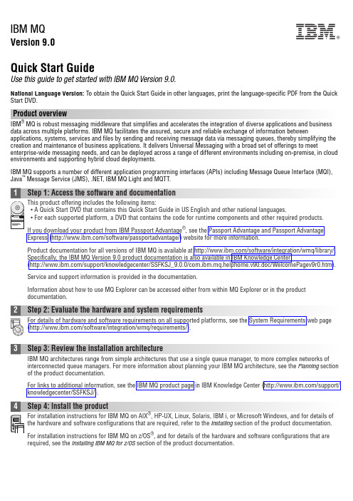
IBM MQVersion 9.0Quick Start GuideUse this guide to get started with IBM MQ Version 9.0.National Language Version:To obtain the Quick Start Guide in other languages, print the language-specific PDF from the Quick Start DVD.Product overviewIBM ®MQ is robust messaging middleware that simplifies and accelerates the integration of diverse applications and business data across multiple platforms. IBM MQ facilitates the assured, secure and reliable exchange of information betweenapplications, systems, services and files by sending and receiving message data via messaging queues, thereby simplifying the creation and maintenance of business applications. It delivers Universal Messaging with a broad set of offerings to meet enterprise-wide messaging needs, and can be deployed across a range of different environments including on-premise, in cloud environments and supporting hybrid cloud deployments.IBM MQ supports a number of different application programming interfaces (APIs) including Message Queue Interface (MQI),Java ™Message Service (JMS), .NET, IBM MQ Light and MQTT.Product documentation for all versions of IBM MQ is available at /software/integration/wmq/library/.Specifically, the IBM MQ Version 9.0 product documentation is also available in IBM Knowledge Center(/support/knowledgecenter/SSFKSJ_9.0.0/com.ibm.mq.helphome.v90.doc/WelcomePagev9r0.htm).Service and support information is provided in the documentation.Information about how to use MQ Explorer can be accessed either from within MQ Explorer or in the product documentation.3Step 3: Review the installation architectureIBM MQ architectures range from simple architectures that use a single queue manager, to more complex networks of interconnected queue managers. For more information about planning your IBM MQ architecture, see the Planning section of the product documentation.For links to additional information, see the IBM MQ product page in IBM Knowledge Center (/support/knowledgecenter/SSFKSJ/).4Step 4: Install the productFor installation instructions for IBM MQ on AIX ®, HP-UX, Linux, Solaris, IBM i, or Microsoft Windows, and for details of the hardware and software configurations that are required, refer to the Installing section of the product documentation.For installation instructions for IBM MQ on z/OS ®, and for details of the hardware and software configurations that are required, see the Installing IBM MQ for z/OS section of the product documentation.IBM®5Step 5: Get startedThe Getting Started scenario in the Scenarios section of the product documentation explains how to get started with IBMMQ on Windows. Use this scenario if you have not used IBM MQ before and want to get started quickly.Further scenarios help you to configure or use product features by taking you through the appropriate task steps. The scenarios include links to other content that helps you to gain a better understanding of the area in which you are interested.More informationFor more information about IBM MQ, see the following resources:Product readme fileThe product readme file (readme.html) is included on the product media and is installed when you install productcomponents. The latest version is available on the product readmes web page (/support/docview.wss?rs=171&uid=swg27006097).IBM Support PortalSupport information available through IBM Support Portal includes the following resources:v Support technotes (/support/search.wss?q=websphere+mq)v Available downloads and other resources (/support/entry/portal/product/websphere/websphere_mq?productContext=24824631)v Systems Middleware Support Social Media Channels (/support/docview.wss?uid=swg21410956#2IBM MQ Version 9.0 Licensed Materials - Property of IBM. © Copyright IBM Corp. 2006, 2016. U.S. Government Users Restricted Rights - Use, duplication or disclosure restricted by GSA ADP Schedule Contract with IBM Corp. IBM, the IBM logo, , AIX, Passport Advantage, WebSphere®and z/OS are trademarks or registered trademarks of International Business Machines Corp., registered in many jurisdictions worldwide. Java and all Java-based trademarks and logos are trademarks or registered trademarks of Oracle and/or its affiliates. Linux is a registered trademark of Linus Torvalds in the United States, other countries, or both. Microsoft, Windows, and the Windows logo are trademarks of Microsoft Corporation in the United States, other countries, or both. Other product and service names might be trademarks of IBM or other companies. A current list of IBM trademarks is available on the Web at “Copyright and trademark information” (/legal/copytrade.shtml).Part Number:CF4IWMLPrinted in Ireland。
DS2208数字扫描器产品参考指南说明书

-05 Rev. A
6/2018
Rev. B Software Updates Added: - New Feedback email address. - Grid Matrix parameters - Febraban parameter - USB HID POS (formerly known as Microsoft UWP USB) - Product ID (PID) Type - Product ID (PID) Value - ECLevel
-06 Rev. A
10/2018 - Added Grid Matrix sample bar code. - Moved 123Scan chapter.
-07 Rev. A
11/2019
Added: - SITA and ARINC parameters. - IBM-485 Specification Version.
No part of this publication may be reproduced or used in any form, or by any electrical or mechanical means, without permission in writing from Zebra. This includes electronic or mechanical means, such as photocopying, recording, or information storage and retrieval systems. The material in this manual is subject to change without notice.
at91sam90的程序烧写

1、文件isp-extram-at91sam9260.bin替换下面程序安装路径下的文件:A TMEL Corporation\A T91-ISP v1.12\SAM-BA v2.8\lib\A T91SAM9260-EK硬件准备:使用镊子短路R309电阻两端,给核心板加电,2s后,松开镊子2、选择串口及目标板类型,connect(串口准备,集中器串口与电脑串口连接)3、如下图所示,先选择DataFlash A T45DB/DCB Enable Dataflash(SPI0 CS0)4、如下图所示《dataflash_at91sam9260ek111.bin》5、如下图所示结束:6、重启终端,在超级终端中看到如下图所示配置串口如下图:重启终端:按照打印输入s,停止打印到U-Boot>按照如下步骤操作:U-Boot> setenv ipaddr 129.1.22.96U-Boot> setenv ethaddr 00:11:22:23:34:23eth_set_enetaddr(num=0, addr=00:11:22:23:34:23) Setting new HW address on macb0New Address is 00:11:22:23:34:23 eth_set_enetaddr(num=0, addr=00:11:22:23:34:23) Setting new HW address on macb0New Address is 00:11:22:23:34:23U-Boot>U-Boot> setenv serverip 129.1.3.32U-Boot> saveenvSaving Environment to dataflash...打开tftpserver(配置电脑ip129.1.3.32),下载内核和文件系统:U-Boot>dnkernelU-Boot>dnrootss。
ATMEL芯片AT91SAM9G45

ATMEL 芯片AT91SAM9G45
介绍一款新的ATMEL 芯片AT91SAM9G45
推荐SAM9G45 开发板主频高达400MHz,可支持WinCE 和Linux 操
作系统的开发板调试,带有256MB NandFlash,2MB NorFlash,512KB EEPROM,4MB DataFlash,以及2 个64MB 的DDR2 SDRAM,并带有丰富的功能扩展:高速USB2.0(480MHz),音频输入,音频输出,10/100Mbps 网络,JTAG 调试接口,DBGU 串口,Micro SD 卡接口,SD/MMC 卡接口
AT91SAM9G45 芯片使用ARM926EJ-S 内核,它带有MMU 功能,有
一个64KB 的内部SRAM 和一个64KB 的内部ROM,并带有两个外部总线
接口,总共可支持4 块DDR2/LPDDR,SDRAM/LPSDR,静态存储器,CF
闪存或带ECC 校验的SLC NAND Flash。
AT91SAM9G45 芯片把用户接口的功能性和高速数据连接相结合,包
括LCD 控制器,电阻触摸屏,相机接口,音频,10/100M 以太网,高速
USB 和SDIO 等等。
随着处理器运行在400MHz 和多个速率超过100Mbps 的外设,AT91SAM9G45 使用高性能和带宽网络或本地存储媒体来提供良好的
用户体验。
AT91SAM9G45 支持最新的DDR2 和NAND 闪存接口来存储程序和数据。
一个与37 个DMA 通道相关的133M 的内部多层总线接口,以及一个双
外部总线接口,和一个能够用来配置紧密耦合内存(TCM)的64K 字节的分布。
伟格兴MSATA技术规格书

WELLCORE○R SSD MSATA W10 SeriesProduct Specification V1.0 May-2012NOTE:INFORMATION IN THIS DOCUMENT IS PROVIDED IN CONNECTION WITH WELLCORE PRODUCTS, NO LICENSE, EXPRESS OR IMPLIED, BY ESTOPPEL OR OTHERWISE, TO ANY INTELLECTUAL PROPERTY RIGHTS IS GRANTED BY THIS DOCUMENT, TO ANY INTELLECTUAL PROPERTY RIGHTS IN WELLCORE PRODUCT OR TECHNOLOGY,ALL PRODUCT SPECIFICATIONS ARE PROVIDED FOR REFERENCE ONLY, INFORMATION IN THIS PRODUCT SPECIFICATION IS SUBJECT TO CHANGE AT ANYTIME WITHOUT NOTICE.Wellcorping Technology Co., Ltd© WELLCORE 2011. All rights reserved Table of Contents1.Introduction (3)1.0 Overview (3)1.1 Capacity Specifications (3)1.2 Product Specifications (4)2. Product numbering scheme (5)3. Functional Block Diagram (6)4. Mechanical Information (7)4.0 Form factor (7)4.1 Pin Locations (8)4.2 Signal Descriptions (8)5. Electrical Characteristics (9)6. Environmental Conditions (9)6.0 Temperature (9)6.1 Shock, Vibration (10)7. Supported Command Sets (11)7.0 ATA Command set (11)7.1 ATA COMMAND SPECIFICATIONS (13)7.2 S M A R T command set (17)8.NCQ Command (22)Wellcorping Technology Co., Ltd1.Introduction1.0 OverviewWELLCORE SSD MSATA W10 Series purely consists of semiconductor devices and NAND flash moving parts. It gives rugged features against shock and vibration, used in extreme environment such as industrial PC or automotive device to increase reliability,The SSD is designed to use the SATA interface efficiently during both READs and WRITEs while delivering bandwidth-focused performance. SSD technology enables en-hanced boot times, faster application load times, reduced power consumption, and ex-tended reliability.1.1 Capacity Specifications. This chapter is about the specifications of the W10 Series MSATA SSD.Part Numbers Capacity Flash typeW10SM5*C-***2GB MLC/SLC 4GB MLC/SLC 8GB MLC/SLC 16GB MLC/SLC 32GB MLC/SLC 64GB MLC/SLC 128GB MLC 256GB MLCTable 1 :Capacity Specifications. The letter ‘ * ’ means some information of the products, please visit the table 2 for more information.1.2 Product Specifications◆Form factor:MSATA(JEDEC:MO-300B). Form size : 50.8mm * 30.0mm * 3.85mm(LxWxH)◆SATA 3Gbps Bandwidth Performance. Sequential Read: Up to 160 MB/s. Sequential Write: Up to 160 MB/s. Random 4 KB Reads: Up to 6000 IOPS. Random 4 KB Writes: Up to 1000 IOPS◆Compliant with Serial ATA Revision 2.6 ,◆Support 1.5Gps/3.0Gps SATA I/II interface◆Supports BCH ECC 16 bits or 24 bits in 1024 bytes◆S M A R T (Self-Monitoring, Analysis and Reporting Technology) ◆Supports (NCQ) AND (TRIM) Command set◆Flash management algorithm:. static and dynamic wear-leveling, bad block management algorithm◆Data retention: 10 years◆Read endurance: unlimited◆Write endurance: >9 years. Condition: 100GB write/ day(SSD capacity=100GB, Nand flash endurance =5000 P/E Cycles, SSD WA=1.5)◆MTBF (Mean Time Between Failures): 2,000,000 hours◆Operating temperature:. Commercial: 0℃ ~ +70℃. Industrial: -40℃ ~ +85℃◆Power Consumption:. Active(write/read): 1.4 W. Idle : 0.5 W. Sleep: 0.3 W◆Weight: Up to 10 g◆Certifications: UL; CE; FCC; SATA-IO; Microsoft WHQL ◆Product Ecological Compliance: ROHSWellcorping Technology Co., Ltd2. Product numbering schemeEXAMPLE:P/N: W10SM5MC-032 ,Please refer to the following table content (Table 2).W1010 S M 5 M C-032032WELLCOR WELLCORPING PINGTechnologyTechnology SSD Controller: 10-JMICRON 20-NOVACHIPS 30-SMI 40-SANDFORCE50-PHISON60-S-SATA P-PATA E-PCIE Form Factor : 25-2.5 Inch 18-1.8 Inch 13-1.3 InchM5-50mm MSATA M7-70mm MSATA P5-50mm MSATA(PCIE) P7-70mm MSATA(PCIE)Z3-ZIF 1.3 Inch Z8-ZIF 1.8 Inch MI-MICRO 1.8寸 CF-CF CARD FA-CFAST CARD LF-LIF HS-HALFSLIMNAND NAND FLASH: FLASH: S-SLCM-MLC Operatingtemperature:C-Commercial (0℃~+70℃) I-Industrial (-40℃~+85℃) M-Military (-55℃~+150℃) capacity:001-1GB* * 512-512GB * * 1TB-1000GB* *Table 2: numbering scheme3. Functional Block DiagramFigure 3:Functional Block Diagram4. Mechanical Information4.0 Form Size: 50.8mm*30.0mm*3.85mm(LxWxH),refer Figure 4Figure 4: Form Size4.1 Pin Locations4.2 Signal DescriptionsPin PinDefinitions DefinitionsPin PinDefinitions DefinitionsP1 N o Connect P2 +3.3V P3 N o Connect P4 GND P5 N o Connect P6 +1.5V(No use)P7 N o Connect P8 N o Connect P9 GNDP10 N o Connect P11 N o Connect P12 N o Connect P13 N o Connect P14 N o Connect P15 GND P16 N o Connect P17 N o Connect P18 GND P19 N o Connect P20 N o Connect P21 GNDP22 N o Connect P23 SATA Differential TX+ based on SSD P24 +3.3V P25 SATA Differential TX- based on SSDP26 GND P27 GND P28 +1.5V(No use) P29 GNDP30 N o Connect P31 SATA Differential RX- based on SSD P32 N o Connect P33 SATA Differential RX+ based on SSDP34 GND P35 GND P36 N o Connect P37 GND P38 N o Connect P39 +3.3V P40 GND P41 +3.3V P42 N o Connect P43 GND P44 N o Connect P45 Vendor(No use) P46 N o Connect P47 Vendor(No use) P48 +1.5V(No use)P49 DAS/DSS(No use) P50 GND P51 Presence DetectionP52+3.3V5. Electrical CharacteristicsElectrical Characteristics Value Operating Voltage for 3.3 V (±5%)Min Max 3.14 V 3.47VPower Consumption (TYPE)Active(write/read)IdleSleep 1.4 W 0.5 W 0.3WNotes:1.Active power measured during execution of MobileMark* 2007 with SATA Link PowerManagement (LPM) enabled.2.Idle power defined as SSD at idle with SATA Link Power Management (LPM) enabled.6. Environmental Conditions6.0 TemperatureCase TemperatureOperating Non-operating Commercial :(0℃ ~ +70℃) Industrial: (-40℃ ~ +85℃)-55 ~ 95 ℃Temperature GradientOperating Non-operating 30 (TYP) ℃/hr 30 (TYP) ℃/hrHumidityOperating Non-operating 5 ~ 95% 5 ~ 95%Wellcorping Technology Co., Ltd6.1 Shock and VibrationShockOperating Non-operating 1,500 G (Max) at 0.5 msec 1,500 G (Max) at 0.5 msecVibrationOperating Non-operating 2.17 GRMS (5-700 Hz) Max3.13 GRMS (5-800 Hz) MaxNotes:1.Temperature gradient measured without condensation.2.Shock specifications assume the SSD is mounted securely with the input vibration applied to the drive-mounting screws.Stimulus may be applied in the X, Y or Z axis. Shock specification is measured using Root Mean Squared (RMS) value.3.Vibration specifications assume the SSD is mounted securely with the input vibration applied to the drive-mounting screws. Stimulus may be applied in the X, Y or Z axis. Vibration specification is measured using Root Mean Squared (RMS) value.Wellcorping Technology Co., Ltd© WELLCORE 2011. All rights reserved Command Name Code PARAMETERS USEDCommand NameCodeSCSNCYDRHDFTCHECK POWER MODEE5h O X X O X X DEVICE CONFIGURATION OVERLAY B1h X X X O X O EXECUTE DIAGNOSTICS 90h X X X O X X FLUSH CACHE E7h X X X O X X FLUSH CACHE EXT EAh X X X O X X IDENTIFY DEVICE ECh X X X O X X IDLEE3h O X X O X X IDLE IMMEDIATE E1h X X X O X X NOP00h F F F O X O INITIALIZE DEVICE PARAMETERS 91h O X X O O X READ BUFFER E4h X X X O X X READ DMA C8h or C9h O O O O O X READ DMA EXT 25h O O O O O X READ FPDMA QUEUED 60h O O O O O O READ LOG EXT 2Fh O O O O O O READ MULTIPLE C4h O O O O O X READ MULTIPLE EXT 29h O O O O O X READ NATIVE MAX ADDRESS F8h X X X O X X READ NATIVE MAX ADDRESS EXT 27h X X X O X X READ SECTOR(S) 20h or 21h O O O O O X READ SECTOR(S) EXT 24h O O O O O X READ VERIFY SECTOR(S) 40h or 41h O O O O O X READ VERIFY SECTOR(S) EXT 42h O O O O O X RECALIBRATE10h X X X O X X SECURITY DISABLE PASSWORD F6h X X X O X X SECURITY ERASE PREPARE F3h X X X O X X SECURITY ERASE UNIT F4h X X X O X X SECURITY FREEZE LOCK F5h X X X O X X SECURITY SET PASSWORDF1hXXXOXX7 ATA General Feature Command Set7.0 ATA Command set.This table with the following paragraphs summarizes the ATA command set.Command TableWellcorping Technology Co., Ltd© WELLCORE 2011. All rights reserved SECURITY UNLOCK F2h X X X O X XSEEK 7xh X X O O O XSET FEATURES EFh O X X O X OSET MAX F9h O O O O O OSET MAX ADDRESS EXT 37h O O O O O XSET MULTIPLE MODE C6h O X X O X XSLEEP E6h X X X O X XSMART B0h X X O O X OSTANDBY E2h X X X O X XSTANDBY IMMEDIATE E0h X X X O X XWRITE BUFFER E8h X X X O X XWRITE DMA CAh or CBh O O O O O XWRITE DMA EXT 35h O O O O O XWRITE DMA FUA EXT 3Dh O O O O O XWRITE FPDMA QUEUED 61h O O O O O OWRITE LOG EXT 3Fh O O O O O XWRITE MULTIPLE C5h O O O O O XWRITE MULTIPLE EXT 39h O O O O O XWRITE MULTIPLE FUA EXT CEh O O O O O XWRITE SECTOR(S) 30h or 31h O O O O O XWRITE SECTOR(S) EXT 34h O O O O O XWRITE VERIFY 3Ch O O O O O ONote:O = Valid, X = Don't careSC = Sector Count RegisterSN = Sector Number RegisterCY = Cylinder Low/High RegisterDR = DEVICE SELECT Bit (DEVICE/HEAD Register Bit 4)HD = HEAD SELECT Bit (DEVICE/HEAD Register Bit 3-0)FT = Features RegisterWellcorping Technology Co., Ltd© WELLCORE 2011. All rights reserved 7.1 ATA COMMAND SPECIFICATIONSCHECK POWER MODE (E5h)The host can use this command to determine the current power management mode.Sector Count result value-00h – device is in Standby mode80h – device is in Idle modeFFh – device is in Active mode or Idle modeDEVICE CONFIGURATION OVERLAY (B1h)Individual Device Configuration Overlay (DCO) feature set commands are identified by the value placed in the Feature field.The subcommands and their respective codes are listed below.Device Configuration Overlay Feature field valuesValue CommandsC0h DEVICE CONFIGURATION RESTOREC1h DEVICE CONFIGURATION FREEZE LOCKC2h DEVICE CONFIGURATION IDENTIFYC3h DEVICE CONFIGURATION SETDEVICE CONFIGURATION RESTORE (B1h/C0h)The DEVICE CONFIGURATION RESTORE command provides a method for a host to restore any setting previously changed by a DEVICE CONFIGURATION SET command and to restore the content of the IDENTIFY DEVICE data, IDENTIFY PACKET DEVICE data, and other feature settings in a device to their factory default settings. The results of thisaction are indicated by the data returned from the Input Data of a DEVICE CONFIGURATION IDENTIFY command.DEVICE CONFIGURATION FREEZE LOCK (B1h/C1h)The DEVICE CONFIGURATION FREEZE LOCK command provides a method for the host to prevent accidental modification of a device's DCO settings. After a device has completed a DEVICE CONFIGURATION FREEZE LOCK command without error, the device shall return command aborted for all DEVICE CONFIGURATION SET, DEVICE CONFIGURATION FREEZE LOCK, DEVICE CONFIGURATION IDENTIFY, and DEVICE CONFIGURATIONRESTORE commands until after the device processes a power-on reset. A device shall be in the factory_config state or thereduced_config state after processing a power-on reset. A device shall not exit the DCO_Locked state as the result of processing a hardware reset or a software reset.Wellcorping Technology Co., Ltd© WELLCORE 2011. All rights reserved DEVICE CONFIGURATION IDENTIFY (B1h/C2h)DEVICE CONFIGURATION IDENTIFY (B1h/C2h)The DEVICE CONFIGURATION IDENTIFY command causes a device to return a 512-byte data structure. The content of this data structure indicates the selectable commands, modes, and feature sets that the device is capable of disabling or modifying through processing of a DEVICE CONFIGURATION SET command. If a DEVICE CONFIGURATION SET command reducing a device's capabilities has completed without error, then:a) the response by a device to an IDENTIFY DEVICE, IDENTIFY PACKET DEVICE, and other commands, exceptthe DEVICE CONFIGURATION IDENTIFY command, shall reflect the reduced set of capabilities; andb) the response by a device to a DEVICE CONFIGURATION IDENTIFY command shall reflect the entire set of selectable capabilities.The phrase “is changeable” indicates that the feature may be disabled by the host using a DEVICE CONFIGURATION SET command. If the feature is not changeable then the device may support the feature but the DEVICE CONFIGURATION SET command shall not affect support of the feature.The format of the Device Configuration Overlay data structure is listed below.DCO Identify data structureWordValueDescription0002hData structure revision number1 0007hMultiword DMA modes supported Bit15:3 ReservedBit2 1 = Reporting support for Multiword DMA mode 2 and below is changeable Bit1 1 = Reporting support for Multiword DMA mode 1 and below is changeable Bit0 1 = Reporting support for Multiword DMA mode 0 is changeable 2 007FhUltra DMA modes supported Bit15:7 ReservedBit6 1 = Reporting support for Ultra DMA mode 6 and below is changeable Bit5 1 = Reporting support for Ultra DMA mode 5 and below is changeable Bit4 1 = Reporting support for Ultra DMA mode 4 and below is changeable Bit3 1 = Reporting support for Ultra DMA mode 3 and below is changeable Bit2 1 = Reporting support for Ultra DMA mode 2 and below is changeable Bit1 1 = Reporting support for Ultra DMA mode 1 and below is changeable Bit0 1 = Reporting support for Ultra DMA mode 0 is changeable 3-6Native MAXLBAMaximum LBA (QWord) Bit63:48 ReservedBit47:0 Maximum LBAWellcorping Technology Co., Ltd© WELLCORE 2011. All rights reserved Word Value Description7 0089h Command set/feature set supported part 1Bit15ReservedBit14 1 = Reporting support for the Write-Read-Verify feature set is changeableBit13 1 = Reporting support for the SMART Conveyance self-test is changeableBit12 1 = Reporting support for the SMART Selective self-test is changeableBit11 1 = Reporting support for the Forced Unit Access is changeable Bit10 Reserved for TLCBit9 1 = Reporting support for the Streaming feature set is changeableBit8 1 = Reporting support for the 48-bit Addressing feature set is changeableBit7 1 = Reporting support for the HPA feature set is changeableBit6 1 = Reporting support for the AAM feature set is changeable Bit5 1 = Reporting support for the TCQ feature set is changeableBit4 1 = Reporting support for the PUIS feature set is changeable Bit3 1 = Reporting support for the Security feature set is changeable Bit2 1 = Reporting support for the SMART error log is changeable Bit1 1 = Reporting support for the SMART self-test is changeable Bit0 1 = Reporting support for the SMART feature set is changeable8 0000h Serial ATA Command set/feature set supportedBit15:5 Reserved for Serial ATABit4 1 = Reporting support for the SSP feature set is changeableBit3 1 = Reporting support for asynchronous notification is changeableBit2 1 = Reporting support for interface power management is changeableBit1 1 = Reporting support for non-zero buffer offsets is changeable Bit0 1 = Reporting support for the NCQ feature set is changeable9 0000h Reserved for Serial ATA 10-20 0000h Reserved21 0000h Command set/feature set supported part 2Bit15 1 = Reporting support for the NV Cache feature set is changeable Bit14 1 = Reporting support for the NV Cache Power Management feature set is changeableBit13 1 = Reporting support for WRITE UNCORRECTABLE EXT is changeableBit12 1 = Reporting support for the Trusted Computing feature set is changeableBit11 1 = Reporting support for the Free-fall Control feature set is changeableBit10:0 Reserved22 0000h Command set/feature set supported part 3Bit15:0 Reserved23-207 0000h Reserved208-254 0000h Vender Specific255Checksum +A5h Integrity wordBit15:8 Checksum Bit7:0 SignatureWellcorping Technology Co., Ltd© WELLCORE 2011. All rights reserved DEVICE CONFIGURATION SET (B1h/C3h)The DEVICE CONFIGURATION SET command allows a host to reduce the set of optional commands, modes, or feature sets supported by a device as indicated by a DEVICE CONFIGURATION IDENTIFY command. The DEVICE CONFIGURATION SET command may modify the data returned by IDENTIFY DEVICE or IDENTIFY PACKET DEVICE. When the IDENTIFY DEVICE data or IDENTIFY PACKET DEVICE data is changed, the device shall respond ina manner consistent with the new data.If a bit is set to one in the DEVICE CONFIGURATION SET data transmitted to the device that is not set in the DCO data received from a DEVICE CONFIGURATION IDENTIFY command, no action is taken for that bit.Modifying the maximum LBA of the device also modifies the LBA value returned by a READ NATIVE MAX ADDRESSor READ NATIVE MAX ADDRESS EXT command.EXECUTE DIAGNOSITICS (90h)This command performs the internal diagnostic tests implemented by the drive. See ERROR register for diagnostic codes.FLUSH CACHE (E7h)This command is used by the host to request the device to flush the write cache. If there is data in the write cache, that data shall be written to the media. The BSY bit shall remain set to one until all data has been successfully written or an error occurs.FLUSH CACHE EXT (EAh)48-bit feature set mandatory command. This command is used by the host to request the device to flush the write cache. If there is data in the write cache, that data shall be written to the media. The BSY bit shall remain set to one until all data has been successfully written or an error occurs.IDENTIFY DEVICE (ECh)This commands read out 512Bytes of drive parameter information. Parameter Information consists of the arrangement and value as shown in the following table. This command enables the host to receive the Identify Drive Information from the device.Wellcorping Technology Co., Ltd© WELLCORE 2011. All rights reserved 7.2 SMART COMMAND SETSMART Function Set (B0h)Performs different processing required for predicting device failures, according to the subcommand specified in the Features register. If the Features register contains an unsupported value, the Aborted Command error is returned. If the SMART function is disabled, any subcommand other than SMART ENABLE OPERATIONS results in the Aborted Command error.Code Smart SubcommandD0h READ DATAD1h READ ATTRIBUTE THRESHOLDSD2h ENABLE/DISABLE ATTRIBUTE AUTOSAVED3h SAVE ATTRIBUTE VALUESD8h ENABLE OPERATIONSD9h DISABLE OPERATIONSDAh RETURN STATUSSMART READ DATA (B0h/D0h)This command returns 512-byte SMART Data Structure to the host with PIO data-in protocol. The register file has to contain D0h for Features register, 4Fh for LBA Mid register and C2h for the LBA High register.Byte Description0-1 Data structure revision number2-13 1st attribute data14-361 2nd-30th Individual attribute data362 Off-line data collection status363 Self-test execution status364-365 Total time in seconds to complete off-line data collection366 Reserved367 Off-line data collection capability368-369 SMART capability370 Error logging capability371 Self-test Failure Checkpoint372 Short self-test routine recommended polling time(in minutes)373 Extended self-test routine recommended polling time(in minutes)374-510 Reserved511 Data structure ChecksumWellcorping Technology Co., Ltd© WELLCORE 2011. All rights reserved Byte 2-361: Individual attribute dataByte Description0 Attribute ID1-2 Status Flag3 Attribute Value4 Worst Ever normalized Attribute Value5-10 Raw Attribute Value11 ReservedThe attribute ID information is listed in the following table:ID Description01h Read Error Rate02h Throughput Performance03h Spin Up Time05h Reallocated Sector Count07h Seek Error Rate08h Seek Time performance09h Power-On hours Count0Ah Spin Retry Count0Ch Drive Power Cycle CountA8h SATA PHY Error CountAAh Bad Block CountADh Erase CountAFh Bad Cluster Table CountC0h Unexpected Power Loss CountC2h TemperatureC5h Current Pending Sector CountF0h Write HeadWellcorping Technology Co., Ltd© WELLCORE 2011. All rights reserved MART READ ATTRIBUTE THRESHOLD (B0h/D1h)This command transfers 512 bytes of drive failure threshold data to the host.Byte Description0-1 Data structure revision number2-361 st th1 – 30 Individual attribute threshold data362-510 Reserved1 – 30 Individual attribute threshold data511 Data structure checksumSMART ENABLE/DISABLE ATTRIBUTE AUTOSAVE (B0h/D2h)This command enables and disables the optional attribute autosave feature of the device. This command may either allow the device, after some vendor specified event, to save the device updated attributes to non-volatile memory; or this command may cause the autosave feature to be disabled. The state of the attribute autosave feature, either enabled or disabled, shall be preserved by the device during all power and reset events.A value of zero written by the host into the device’s Count field before issuing this command shall cause this feature to be disabled. Disabling this feature does not preclude the device from saving SMART data to non-volatile memory during some other normal operation (e.g., during a power-on or power-off sequence or during an error recovery sequence).A value of F1h written by the host into the device’s Count field before issuing this command shall cause this feature to be enabled. Any other other non-zero value written by the host into this field before issuing this command is vendor specific. The meaning of any non-zero value written to this field at this time shall be preserved by the device during all power and reset events.SMART SAVE ATTRIBUTE VALUE (B0h/D3h)Saves any modified attribute values.SMART ENABL OPERATIONS (B0h/D8h)Enables the SMART function. This setting is maintained when the power is turned off and then back on. Once the SMART function is enabled, subsequent SMART ENABLE OPERATIONS commands do not affect any parameters.SMART DISABLE OPERATIONS (B0h/D9h)Disables the SMART function. Upon receiving the command, the drive disables all SMART operations. This setting is maintained when the power is turned off and then back on. Once this command has been received, all SMART commands other than SMART ENABLE OPERATIONS are aborted with the Aborted Command error.This command disables all SMART capabilities including any and all timer and event count functions related exclusively to this feature. After command acceptance, this controller will disable all SMART operations. SMART data in no longer be monitored or saved. The state of SMART is preserved across power cycles.Wellcorping Technology Co., Ltd© WELLCORE 2011. All rights reserved SMART RETURN STATUS (B0h/DAh)Reports the drive reliability status.Values reported when a predicted defect has not been detected:Cylinder Low register: 4FhCylinder High register: C2hValues reported when a predicted defect has been detected:Cylinder Low register: F4hCylinder High register: 2ChSTANDBY (E2h)This command causes the device to enter the Standby mode. If the Count field is non-zero then the Standby timer shall be enabled. The value in the Count field shall be used to determine the time programmed into the Standby timer. If the Count field is zero then the Standby timer is disabled.STANDBY IMMEDIATE (E0h)This command causes the drive to set BSY, enter the Sleep mode (which corresponds to the ATA “Standby” Mode), clear BSY and return the interrupt immediately.WRITE BUFFER (E8h)This command enables the host to write the contents of one 512-byte block of data to the device’s buffer. The READ BUFFER and WRITE BUFFER commands shall be synchronized within the device such that sequential WRITE BUFFER and READ BUFFER commands access the same bytes within the buffer.WRITE DMA (CAh)Write data to sectors during Ultra DMA and Multiword DMA transfer. Use the SET FEATURES command to specify the mode value.WRITE DMA EXT (35h)48-bit feature set mandatory command. Write data to sectors during Ultra DMA and Multiword DMA transfer. Use the SET FEATURES command to specify the mode value.WRITE DMA FUA EXT (3Dh)48-bit feature set mandatory command. This command provides the same function as the WRITE DMA EXT command except that regardless of whether volatile and/or non-volatile write caching in the device is enabled or not, the user data shall be written to non-volatile media before command completion is reported.WRITE FPDMA QUEUED (61h)NCQ feature set mandatory 48-bit command. This command causes data to be transferred from the host to the device.Wellcorping Technology Co., Ltd© WELLCORE 2011. All rights reserved WRITE LOG EXT (3Fh)This command writes a specified number of 512 byte blocks of data to the specified log.WRITE MULTIPLE (C5h)This command writes the number of logical sectors specified in the Count field. The number of logical sectors per DRQ data block is defined by the content of IDENTIFY DEVICE data word 59. If the number of requested logical sectors is not evenly divisible by the DRQ data block count, as many full blocks as possible are transferred, followed by a final, partial block transfer. The partial block transfer is for n logical sectors, where:n = Remainder (Count / DRQ data block count).Device errors encountered during WRITE MULTIPLE commands are posted after the attempted device write of the DRQ data block or partial DRQ data block is transferred. The command ends with the logical sector in error, even if the error was in the middle of a DRQ data block. Subsequent DRQ data blocks are not transferred in the event of an error.The contents of the Command Structure following the transfer of a DRQ data block that had a logical sector in error are undefined. The host should retry the transfer as individual requests to obtain valid error information. If IDENTIFY DEVICE data word 59 bit 8 is cleared to zero or IDENTIFY DEVICE data word 59 bits (7:0) are set to zero, and a WRITE MULTIPLE command is received by the device, and no successful SET MULTIPLE MODE command has been processed by the device, the device shall return command aborted. A successful SET MULTIPLE MODE command should precede a WRITE MULTIPLE command.WRITE MULTIPLE EXT (39h)48-bit feature set mandatory command. This command is similar to the Write Sectors command. Interrupts are not presented on each sector, but on the transfer of a block which contains the number of sectors defined by Set Multiple command.WRITE MULTIPLE FUA EXT (CEh)48-bit feature set mandatory command. This command provides the same functionality as the WRITE MULTIPLE EXT command except that regardless of whether volatile and/or non-volatile write caching in the device is enabled or not, the user data shall be written to non-volatile media before command completion is reported.WRITE SECTOR(S) (30h/31h)Write data to a specified number of sectors (1 to 256, as specified with the Sector Count register) from the specified address. Specify “00h” to write 256 sectors.WRITE SECTOR(S) EXT (34h)48-bit feature set mandatory command. Write data to a specified number of sectors (1 to 65536, as specified with the Sector Count register) from the specified address. Specify “00h” to write 65536 sectors.WRITE VERIFY (3Ch)This command is similar to the WRITE SECTOR(S) command, except that each sector is verified before the command is completed.Wellcorping Technology Co., Ltd8 NCQNCQ-Native Command QueuingThe WELLCORE W10 Series supports the Native Command Queuing (NCQ) command set, which includes:•READ FPDMA QUEUED•WRITE FPDMA QUEUEDNote:With a maximum queue depth equal to 32.Wellcorping Technology Co., Ltd。
cisco san 配置

CCSP, CCVP, the Cisco Square Bridge logo, Follow Me Browsing, and StackWise are trademarks of Cisco Systems, Inc.; Changing the Way We Work, Live, Play, and Learn, and iQuick Study are service marks of Cisco Systems, Inc.; and Access Registrar, Aironet, BPX, Catalyst, CCDA, CCDP, CCIE, CCIP, CCNA, CCNP, Cisco, the Cisco Certified Internetwork Expert logo, Cisco IOS, Cisco Press, Cisco Systems, Cisco Systems Capital, the Cisco Systems logo, Cisco Unity, Enterprise/Solver, EtherChannel, EtherFast, EtherSwitch, Fast Step, FormShare, GigaDrive, GigaStack, HomeLink, Internet Quotient, IOS, IP/TV, iQ Expertise, the iQ logo, iQ Net Readiness Scorecard, LightStream, Linksys, MeetingPlace, MGX, the Networkers logo, Networking Academy, Network Registrar, Packet, PIX, Post-Routing, Pre-Routing, ProConnect, RateMUX, ScriptShare, SlideCast, SMARTnet, The Fastest Way to Increase Your Internet Quotient, and TransPath are registered trademarks of Cisco Systems, Inc. and/or its affiliates in the United States and certain other countries. All other trademarks mentioned in this document or Website are the property of their respective owners. The use of the word partner does not imply a partnership relationship between Cisco and any other company. (0601R)
AT91SAM9G20资料

Features Array•Incorporates the ARM926EJ-S™ ARM® Thumb® Processor–DSP Instruction Extensions, ARM Jazelle® Technology for Java® Acceleration–32-KByte Data Cache, 32-KByte Instruction Cache, Write Buffer–CPU Frequency 400 MHz–Memory Management Unit–EmbeddedICE™, Debug Communication Channel Support•Additional Embedded Memories–One 64-KByte Internal ROM, Single-cycle Access at Maximum Matrix Speed–Two 16-KByte Internal SRAM, Single-cycle Access at Maximum Matrix Speed •External Bus Interface (EBI)–Supports SDRAM, Static Memory, ECC-enabled NAND Flash and CompactFlash®•USB 2.0 Full Speed (12 Mbits per second) Device Port–On-chip Transceiver, 2,432-byte Configurable Integrated DPRAM•USB 2.0 Full Speed (12 Mbits per second) Host and Double Port–Single or Dual On-chip Transceivers–Integrated FIFOs and Dedicated DMA Channels•Ethernet MAC 10/100 Base T–Media Independent Interface or Reduced Media Independent Interface–128-byte FIFOs and Dedicated DMA Channels for Receive and Transmit•Image Sensor Interface–ITU-R BT. 601/656 External Interface, Programmable Frame Capture Rate–12-bit Data Interface for Support of High Sensibility Sensors–SAV and EAV Synchronization, Preview Path with Scaler, YCbCr Format•Bus Matrix–Six 32-bit-layer Matrix–Boot Mode Select Option, Remap Command•Fully-featured System Controller, including–Reset Controller, Shutdown Controller–Four 32-bit Battery Backup Registers for a Total of 16 Bytes–Clock Generator and Power Management Controller–Advanced Interrupt Controller and Debug Unit–Periodic Interval Timer, Watchdog Timer and Real-time Timer•Reset Controller (RSTC)–Based on a Power-on Reset Cell, Reset Source Identification and Reset OutputControl•Clock Generator (CKGR)–Selectable 32,768 Hz Low-power Oscillator or Internal Low Power RC Oscillator on Battery Backup Power Supply, Providing a Permanent Slow Clock–3 to 20 MHz On-chip Oscillator, One up to 800 MHz PLL and One up to 100 MHz PLL •Power Management Controller (PMC)–Very Slow Clock Operating Mode, Software Programmable Power OptimizationCapabilities–Two Programmable External Clock Signals•Advanced Interrupt Controller (AIC)–Individually Maskable, Eight-level Priority, Vectored Interrupt Sources–Three External Interrupt Sources and One Fast Interrupt Source, SpuriousInterrupt Protected•Debug Unit (DBGU)–2-wire UART and Support for Debug Communication Channel, Programmable ICE Access Prevention–Mode for General Purpose 2-wire UART Serial Communication26384CS–ATARM–11-Mar-09AT91SAM9G20 Summary•Periodic Interval Timer (PIT)–20-bit Interval Timer plus 12-bit Interval Counter •Watchdog Timer (WDT)–Key-protected, Programmable Only Once, Windowed 16-bit Counter Running at Slow Clock •Real-time Timer (RTT)–32-bit Free-running Backup Counter Running at Slow Clock with 16-bit Prescaler •One 4-channel 10-bit Analog-to-Digital Converter•Three 32-bit Parallel Input/Output Controllers (PIOA, PIOB, PIOC)–96 Programmable I/O Lines Multiplexed with up to Two Peripheral I/Os –Input Change Interrupt Capability on Each I/O Line–Individually Programmable Open-drain, Pull-up Resistor and Synchronous Output –All I/O Lines are Schmitt Trigger Inputs •Peripheral DMA Controller Channels (PDC)•One Two-slot MultiMedia Card Interface (MCI)–SDCard/SDIO and MultiMediaCard ™ Compliant–Automatic Protocol Control and Fast Automatic Data Transfers with PDC •One Synchronous Serial Controller (SSC)–Independent Clock and Frame Sync Signals for Each Receiver and Transmitter –I²S Analog Interface Support, Time Division Multiplex Support–High-speed Continuous Data Stream Capabilities with 32-bit Data Transfer •Four Universal Synchronous/Asynchronous Receiver Transmitters (USART)–Individual Baud Rate Generator, IrDA ® Infrared Modulation/Demodulation, Manchester Encoding/Decoding –Support for ISO7816 T0/T1 Smart Card, Hardware Handshaking, RS485 Support –Full Modem Signal Control on USART0•Two 2-wire UARTs•Two Master/Slave Serial Peripheral Interfaces (SPI)–8- to 16-bit Programmable Data Length, Four External Peripheral Chip Selects –Synchronous Communications•Two Three-channel 16-bit Timer/Counters (TC)–Three External Clock Inputs, Two Multi-purpose I/O Pins per Channel –Double PWM Generation, Capture/Waveform Mode, Up/Down Capability –High-Drive Capability on Outputs TIOA0, TIOA1, TIOA2•One Two-wire Interface (TWI)–Compatible with Standard Two-wire Serial Memories –One, Two or Three Bytes for Slave Address –Sequential Read/Write Operations–Master, Multi-master and Slave Mode Operation –Bit Rate: Up to 400 Kbits–General Call Supported in Slave Mode–Connection to Peripheral DMA Controller (PDC) Channel Capabilities Optimizes Data Transfers in Master Mode •IEEE ® 1149.1 JTAG Boundary Scan on All Digital Pins •Required Power Supplies–0.9V to 1.1V for VDDBU, VDDCORE, VDDPLL –1.65 to 3.6V for VDDOSC–1.65V to 3.6V for VDDIOP (Peripheral I/Os) –3.0V to 3.6V for VDDUSB–3.0V to 3.6V VDDANA (Analog-to-digital Converter)–Programmable 1.65V to 1.95V or 3.0V to 3.6V for VDDIOM (Memory I/Os)•Available in a 217-ball LFBGA and 247-ball TFBGA RoHS-compliant Package36384CS–ATARM–11-Mar-09AT91SAM9G20 Summary1.DescriptionThe AT91SAM9G20 is based on the integration of an ARM926EJ-S processor with fast ROM and RAM memories and a wide range of peripherals.The AT91SAM9G20 embeds an Ethernet MAC, one USB Device Port, and a USB Host control-ler. It also integrates several standard peripherals, such as the USART, SPI, TWI, Timer Counters, Synchronous Serial Controller, ADC and MultiMedia Card Interface.The AT91SAM9G20 is architectured on a 6-layer matrix, allowing a maximum internal bandwidth of six 32-bit buses. It also features an External Bus Interface capable of interfacing with a wide range of memory devices.The AT91SAM9G20 is an enhancement of the AT91SAM9260 with the same peripheral fea-tures. It is pin-to-pin compatible with the exception of power supply pins. Speed is increased to reach 400 MHz on the ARM core and 133 MHz on the system bus and EBI.46384CS–ATARM–11-Mar-09AT91SAM9G20 Summary2.AT91SAM9G20 Block DiagramFigure 2-1.AT91SAM9G20 Block Diagram56384CS–ATARM–11-Mar-09AT91SAM9G20 Summary3.Signal DescriptionTable 3-1.Signal Description List (Continued)Signal Name FunctionTypeActive LevelCommentsPower SuppliesVDDIOM EBI I/O Lines Power Supply Power 1.65V to 1.95V or 3.0V to 3.6V VDDIOP Peripherals I/O Lines Power Supply Power 1.65V to 3.6V VDDBU Backup I/O Lines Power Supply Power 0.9V to 1.1V VDDANA Analog Power Supply Power 3.0V to 3.6V VDDPLL PLL Power Supply Power 0.9V to 1.1V VDDOSC Oscillator Power Supply Power 1.65V to 3.6V VDDCORE Core Chip Power Supply Power 0.9V to 1.1V VDDUSB USB Power Supply Power 1.65V to 3.6VGND Ground Ground GNDANA Analog Ground Ground GNDBU Backup Ground Ground GNDUSB USB Ground Ground GNDPLL PLL Ground GroundClocks, Oscillators and PLLsXIN Main Oscillator Input Input XOUT Main Oscillator Output Output XIN32Slow Clock Oscillator Input Input XOUT32Slow Clock Oscillator Output Output OSCSEL Slow Clock Oscillator Selection Input Accepts between 0V and VDDBU.PCK0 - PCK1Programmable Clock Output Output Shutdown, Wakeup LogicSHDN Shutdown Control Output WKUPWake-up InputInputAccepts between 0V and VDDBU.ICE and JTAGNTRST Test Reset Signal Input LowPull-up resistor TCK Test Clock Input No pull-up resistor TDI Test Data In Input No pull-up resistor TDO Test Data Out Output TMS Test Mode Select Input No pull-up resistorJTAGSEL JTAG Selection Input Pull-down resistor. Accepts between 0V and VDDBU.RTCKReturn Test ClockOutput66384CS–ATARM–11-Mar-09AT91SAM9G20 SummaryReset/TestNRST Microcontroller Reset I/O LowPull-up resistorTSTTest Mode SelectInputPull-down resistor. Accepts between 0V and VDDBU.BMS Boot Mode SelectInputNo pull-up resistorBMS = 0 when tied to GND.BMS = 1 when tied to VDDIOP .Debug Unit - DBGUDRXD Debug Receive Data Input DTXD Debug Transmit Data Output Advanced Interrupt Controller - AICIRQ0 - IRQ2External Interrupt Inputs Input FIQ Fast Interrupt Input Input PIO Controller - PIOA - PIOB - PIOCP A0 - P A31Parallel IO Controller A I/O Pulled-up input at reset PB0 - PB31Parallel IO Controller B I/O Pulled-up input at reset PC0 - PC31Parallel IO Controller C I/O Pulled-up input at reset External Bus Interface - EBID0 - D31Data Bus I/O Pulled-up input at reset A0 - A25Address Bus Output 0 at resetNWAIT External Wait Signal Input Low Static Memory Controller - SMCNCS0 - NCS7Chip Select Lines Output Low NWR0 - NWR3Write Signal Output Low NRD Read Signal Output Low NWE Write Enable Output Low NBS0 - NBS3Byte Mask SignalOutputLowCompactFlash SupportCFCE1 - CFCE2CompactFlash Chip Enable Output Low CFOE CompactFlash Output Enable Output Low CFWE CompactFlash Write Enable Output Low CFIOR CompactFlash IO Read Output Low CFIOW CompactFlash IO Write Output Low CFRNW CompactFlash Read Not Write Output CFCS0 - CFCS1CompactFlash Chip Select LinesOutputLow Table 3-1.Signal Description List (Continued)Signal Name FunctionTypeActive LevelComments76384CS–ATARM–11-Mar-09AT91SAM9G20 SummaryNAND Flash SupportNANDCS NAND Flash Chip Select Output Low NANDOE NAND Flash Output Enable Output Low NANDWE NAND Flash Write EnableOutput Low NANDALE NAND Flash Address Latch Enable Output Low NANDCLE NAND Flash Command Latch Enable Output Low SDRAM ControllerSDCK SDRAM Clock Output SDCKE SDRAM Clock Enable Output High SDCS SDRAM Controller Chip Select Output Low BA0 - BA1Bank SelectOutput SDWE SDRAM Write Enable Output Low RAS - CAS Row and Column Signal Output Low SDA10SDRAM Address 10 Line Output Multimedia Card Interface MCIMCCK Multimedia Card ClockOutput MCCDAMultimedia Card Slot A Command I/O MCDA0 - MCDA3Multimedia Card Slot A Data I/O MCCDBMultimedia Card Slot B Command I/O MCDB0 - MCDB3Multimedia Card Slot B Data I/O Universal Synchronous Asynchronous Receiver Transmitter USARTxSCKx USARTx Serial Clock I/O TXDx USARTx Transmit Data I/O RXDx USARTx Receive Data Input RTSx USARTx Request T o Send Output CTSx USARTx Clear T o Send Input DTR0USART0 Data T erminal Ready Output DSR0USART0 Data Set Ready Input DCD0USART0 Data Carrier Detect Input RI0USART0 Ring Indicator Input Synchronous Serial Controller - SSCTD SSC Transmit Data Output RD SSC Receive Data Input TK SSC Transmit Clock I/O RK SSC Receive Clock I/O TF SSC Transmit Frame Sync I/O RFSSC Receive Frame SyncI/OTable 3-1.Signal Description List (Continued)Signal Name FunctionTypeActive LevelComments86384CS–ATARM–11-Mar-09AT91SAM9G20 SummaryTimer/Counter - TCxTCLKx TC Channel x External Clock Input Input TIOAx TC Channel x I/O Line A I/O TIOBx TC Channel x I/O Line B I/O Serial Peripheral Interface - SPIx_SPIx_MISO Master In Slave Out I/O SPIx_MOSI Master Out Slave In I/O SPIx_SPCK SPI Serial ClockI/O SPIx_NPCS0SPI Peripheral Chip Select 0I/O Low SPIx_NPCS1-SPIx_NPCS3SPI Peripheral Chip Select Output Low Two-Wire InterfaceTWD Two-wire Serial Data I/O TWCK Two-wire Serial ClockI/O USB Host PortHDP A USB Host Port A Data +Analog HDMA USB Host Port A Data -Analog HDPB USB Host Port B Data +Analog HDMB USB Host Port B Data -Analog USB Device PortDDM USB Device Port Data -Analog DDP USB Device Port Data +Analog Ethernet 10/100ETXCK Transmit Clock or Reference Clock Input MII only, REFCK in RMII ERXCK Receive Clock Input MII onlyETXEN Transmit Enable Output ETX0-ETX3Transmit Data Output ETX0-ETX1 only in RMII ETXER Transmit Coding Error Output MII onlyERXDV Receive Data Valid Input RXDV in MII, CRSDV in RMII ERX0-ERX3Receive Data Input ERX0-ERX1 only in RMII ERXER Receive ErrorInput ECRS Carrier Sense and Data Valid Input MII only ECOL Collision DetectInput MII onlyEMDC Management Data Clock Output EMDIOManagement Data Input/OutputI/OTable 3-1.Signal Description List (Continued)Signal Name FunctionTypeActive LevelComments96384CS–ATARM–11-Mar-09AT91SAM9G20 SummaryNote:No PLLRCA line present on the A T91SAM9G20.4.Package and Pinout•The AT91SAM9G20 is available in a 217-ball, 15 x 15 mm, LFBGA package (0.8 mm pitch) (Figure 4-1).•The AT91SAM9G20 is available in a 247-ball, 10 x 10 x 1.1 mm, TFBGA Green package, , (0.5 mm pitch) (Figure 4-2).4.1217-ball LFBGA Package OutlineFigure 4-1 shows the orientation of the 217-ball LFBGA package.A detailed mechanical description is given in the section “AT91SAM9G20 Mechanical Charac-teristics” of the product datasheet.Figure 4-1.217-ball LFBGA Package (Top View)Image Sensor InterfaceISI_D0-ISI_D11 Image Sensor DataInput ISI_MCK Image Sensor Reference Clock Output ISI_HSYNC Image Sensor Horizontal Synchro Input ISI_VSYNC Image Sensor Vertical Synchro Input ISI_PCK Image Sensor Data clock Input Analog to Digital ConverterAD0-AD3Analog InputsAnalog Digital pulled-up inputs at resetADVREF Analog Positive Reference Analog ADTRG ADC TriggerInputTable 3-1.Signal Description List (Continued)Signal Name FunctionTypeActive LevelComments106384CS–ATARM–11-Mar-09AT91SAM9G20 Summary4.2217-ball LFBGA PinoutTable 4-1.Pinout for 217-ball LFBGA PackagePinSignal NamePinSignal NamePinSignal NamePinSignal NameA1CFIOW/NBS3/NWR3D5A5J14TDO P17PB5A2NBS0/A0D6GND J15PB19R1NCA3NWR2/NBS2/A1D7A10J16TDI R2GNDANA A4A6D8GNDJ17PB16R3PC29A5A8D9VDDCORE K1PC24R4VDDANA A6A11D10GNDUSB K2PC20R5PB12A7A13D11VDDIOM K3D15R6PB23A8BA0/A16D12GNDUSB K4PC21R7GND A9A18D13DDM K8GND R8PB26A10A21D14HDPB K9GND R9PB28A11A22D15NCK10GND R10PA0A12CFWE/NWE/NWR0D16VDDBU K14PB4R11PA4A13CFOE/NRD D17XIN32K15PB17R12PA5A14NCS0E1D10K16GND R13PA10A15PC5E2D5K17PB15R14PA21A16PC6E3D3L1GND R15PA23A17PC4E4D4L2PC26R16PA24B1SDCKE14HDPA L3PC25R17PA29B2CFIOR/NBS1/NWR1E15HDMA L4VDDOSC T1NCB3SDCS/NCS1E16GNDBU L14PA28T2GNDPLL B4SDA10E17XOUT32L15PB9T3PC0B5A3F1D13L16PB8T4PC1B6A7F2SDWE L17PB14T5PB10B7A12F3D6M1VDDCORE T6PB22B8A15F4GND M2PC31T7GND B9A20F14OSCSEL M3GND T8PB29B10NANDWE F15BMSM4PC22T9PA2B11PC7F16JTAGSEL M14PB1T10PA6B12PC10F17TST M15PB2T11PA8B13PC13G1PC15M16PB3T12PA11B14PC11G2D7M17PB7T13VDDCORE B15PC14G3SDCKE N1XINT14PA20B16PC8G4VDDIOM N2VDDPLL T15GND B17WKUP G14GND N3PC23T16PA22C1D8G15NRST N4PC27T17PA27C2D1G16RTCK N14PA31U1GNDPLL C3CAS G17TMS N15PA30U2ADVREF C4A2H1PC18N16PB0U3PC2C5A4H2D14N17PB6U4PC3C6A9H3D12P1XOUT U5PB20C7A14H4D11P2VDDPLL U6PB21C8BA1/A17H8GND P3PC30U7PB25C9A19H9GND P4PC28U8PB27C10NANDOE H10GNDP5PB11U9PA12C11PC9H14VDDCORE P6PB13U10PA13C12PC12H15TCK P7PB24U11PA14C13DDP H16NTRST P8VDDIOP U12PA15C14HDMB H17PB18P9PB30U13PA19C15NCJ1PC19P10PB31U14PA17C16VDDUSB J2PC17P11PA1U15PA16C17SHDN J3VDDIOM P12PA3U16PA18D1D9J4PC16P13PA7U17VDDIOPD2D2J8GND P14PA9D3RAS J9GND P15PA26D4D0J10GNDP16PA25116384CS–ATARM–11-Mar-09AT91SAM9G20 Summary4.3247-ball TFBGA Package OutlineFigure 4-2 shows the orientation of the 247-ball TFBGA package.A detailed mechanical description is given in the section “AT91SAM9G20 Mechanical Charac-teristics” of the product datasheet.Figure 4-2.126384CS–ATARM–11-Mar-09AT91SAM9G20 Summary4.4247-ball TFBGA Package PinoutTable 4-2.Pinout for 247-ball TFBGA PackagePinSignal NamePinSignal NamePinSignal NamePinSignal NameA1D13F7CFIOR/NBS1/NWR1K10GND P17RTCK A2D12F8SDA10K11VDDIOM P18PB16A12A9F9NBS0/A0K12GND R2GND A14A13F10A6K13GND R3PB29A16A20F11A12K14XOUT32R5PB26A18A22F12A15K15XIN32R6PB27A19NANDOE F13BA1/A17K17HDP A R7P A5B1D15F14PC10K18HDMA R8GND B2D14F15PC14L2NC R9P A12B3D10F16VDDUSB L3NCR10GND B4D9F17PC9L5ADVREF R11P A19B5D7F18PC12L6PC2R12P A26B6D3G2PC26L7GND R13PB1B7D2G3PC25L8GND R14GND B8RAS G5PC24L9GND R15PB7B9CASG6PC21L10GNDR17PB14B10NWR2/NBS2/A1G8VDDCORE L11VDDCORE R18PB9B11A3G9A5L12GND T2P A1B13A10G10VDDCORE L13OSCSEL T3PB10B15A18G11VDDCORE L14GNDBU T17PB19B17A21G12VDDCORE L15GND T18PB17B19VDDUSB G14PC13L17NRST U2GNDANA C2PC15G15GNDL18TCK U3PB21C3D11G17GNDUSB M2PC0U4PB28C4D8G18PC11M3PC1U5PB31C5SDCKE H2PC31M5PC3U6P A4C6SDWE H3PC30M6NTRST U7P A3C7SDCK H5PC28M7GND U8P A9C8D1H6PC27M8GND U9GND C9SDCS/NCS1H7PC29M9GND U10P A15C10A2H8GND M10P A16U11P A21C11A7H9GND M11VDDCORE U12P A25C12A11H10VDDIOM M12GND U13P A29C14A19H11VDDIOM M13VDDIOP U14P A27C16GNDUSBH12GNDM14TSTU15P A31C18CFWE/NWE/NWR0H13VDDCORE M15JT AGSEL U16GND D2PC17H14SHDW M17PB18U17PB2D3PC16H15VDDBU M18TMS U18GND D13A14H17HDPB N2PB20V1PB12D15NANDWE H18HDMB N3PB13V2PB23D17CFOE/NRD J2VDDOSC N5PB11V3PB30D19NCS0J3VDDPLL N6BMS V4P A2E2PC18J5XOUT N8GND V5P A8E3PC19J6XINN11P A17V6P A10E5D6J7VDDPLL N12P A23V7P A13E6D5J8GND N14GND V8VDDIOP E7D0J9VDDIOM N15VDDIOP V9P A14E8CFIOW/NBS3/NWR3J10VDDIOM N17TDO V10VDDIOP E9GND J11VDDIOM N18TDI V11P A20E10A4J12GND P2PB24V12P A22E11A8J13GND P3PB22V13VDDIOP E12VDDIOM J14WKUP P5GND V14P A30E13BA0/A16J15DDP P6GND V15PB0E14PC8J17DDM P7P A6V16GND E15PC4J18VDDIOP P8P A7V17PB4E16PC5K2GNDPLL P9P A11V18GND E18PC7K3GND P10GND V19PB6E19PC6K5NCP11P A18W1PB25F2PC22K6GNDPLL P12P A24W2P A0F3PC23K7VDDANA P13P A28W18PB8F5PC20K8GND P14PB3W19PB15F6D4K9GNDP15PB5136384CS–ATARM–11-Mar-09AT91SAM9G20 Summary5.Power Considerations5.1Power SuppliesThe AT91SAM9G20 has several types of power supply pins:•VDDCORE pins: Power the core, including the processor, the embedded memories and the peripherals; voltage ranges from 0.9V to 1.1V , 1.0V nominal.•VDDIOM pins: Power the External Bus Interface I/O lines; voltage ranges between 1.65V and 1.95V (1.8V typical) or between 3.0V and 3.6V (3.3V nominal). The voltage range is selectable by software.•VDDIOP pins: Power the Peripherals I/O lines; voltage ranges from 1.65V to 3.6V . •VDDBU pin: Powers the Slow Clock oscillator, the internal RC oscillator and a part of the System Controller; voltage ranges from 0.9V to 1.1V , 1.0V nominal.•VDDPLL pin: Powers the PLL cells; voltage ranges from 0.9V to 1.1V .•VDDOSC pin: Powers the Main Oscillator cells; voltage ranges from 1.65V to 3.6V•VDDANA pin: Powers the Analog to Digital Converter; voltage ranges from 3.0V to 3.6V, 3.3V nominal.•VDDUSB pin: Powers USB transceiver; voltage ranges from 3.0V to 3.6V .Ground pins GND are common to VDDCORE, VDDIOM, VDDOSC and VDDIOP pins power supplies. Separated ground pins are provided for VDDBU, VDDPLL, VDDUSB and VDDANA.These ground pins are respectively GNDBU, GNDPLL, GNDUSB and GNDANA.5.2Power ConsumptionThe AT91SAM9G20 consumes about 4 mA of static current on VDDCORE at 25°C. This static current rises at up to 18 mA if the temperature increases to 85°C.On VDDBU, the current does not exceed 9 µA at 25°C. This static current rises at up to 18 µA if the temperature increases to 85°C.For dynamic power consumption, the AT91SAM9G20 consumes a maximum of 50 mA on VDDCORE at maximum conditions (1.0V, 25°C, rises to 80mA at 85°C, processor running full-performance algorithm out of high-speed memories).5.3Programmable I/O LinesThe power supplies pins VDDIOM accept two voltage ranges. This allows the device to reach its maximum speed either out of 1.8V or 3.3V external memories.The maximum speed is 133 MHz on the pin SDCK (SDRAM Clock) loaded with 10 pF. The other signals (control, address and data signals) do not go over 66 MHz, loaded with 30 pF for power supply at 1.8V and 50 pF for power supply at 3.3V.The EBI I/Os accept two slew rate modes, Fast and Slow. This allows to adapt the rising and fall-ing time on SDRAM clock, control and data to the bus load.The voltage ranges and the slew rates are determined by programming VDDIOMSEL and IOSR bits in the Chip Configuration registers located in the Matrix User Interface.At reset, the selected voltage defaults to 3.3V nominal and power supply pins can accept either 1.8V or 3.3V. The user must make sure to program the EBI voltage range before getting the device out of its Slow Clock Mode.At reset, the selected slew rates defaults are Fast.146384CS–ATARM–11-Mar-09AT91SAM9G20 Summary6.I/O Line Considerations6.1JTAG Port PinsTMS, TDI and TCK are schmitt trigger inputs and have no pull-up resistors.TDO and RTCK are outputs, driven at up to VDDIOP, and have no pull-up resistor.The JTAGSEL pin is used to select the JTAG boundary scan when asserted at a high level. It integrates a permanent pull-down resistor of about 15 k Ω to GND, so that it can be left uncon-nected for normal operations.The NTRST signal is described in the Reset Pins paragraph.All the JTAG signals are supplied with VDDIOP.6.2Test PinThe TST pin is used for manufacturing test purposes when asserted high. It integrates a perma-nent pull-down resistor of about 15 k Ω to GNDBU, so that it can be left unconnected for normal operations. Driving this line at a high level leads to unpredictable results.This pin is supplied with VDDBU.6.3Reset PinsNRST is an open-drain output integrating a non-programmable pull-up resistor. It can be driven with voltage at up to VDDIOP.NTRST is an input which allows reset of the JTAG Test Access port. It has no action on the processor.As the product integrates power-on reset cells, which manages the processor and the JTAG reset, the NRST and NTRST pins can be left unconnected.The NRST and NTRST pins both integrate a permanent pull-up resistor of 100 k Ω minimum to VDDIOP.The NRST signal is inserted in the Boundary Scan.6.4PIO ControllersAll the I/O lines are Schmitt trigger inputs and all the lines managed by the PIO Controllers inte-grate a programmable pull-up resistor of 75 k Ω typical with the exception of P4 - P31. For details,refer to the section “AT91SAM9G20 Electrical Characteristics”. Programming of this pull-up resistor is performed independently for each I/O line through the PIO Controllers.6.5I/O Line Drive LevelsThe PIO lines drive current capability is described in the DC Characteristics section of the prod-uct datasheet.6.6Shutdown Logic PinsThe SHDN pin is a tri-state output only pin, which is driven by the Shutdown Controller. There is no internal pull-up. An external pull-up to VDDBU is needed and its value must be higher than 1M Ω. The resisitor value is calculated according to the regulator enable implementation and the SHDN level.156384CS–ATARM–11-Mar-09AT91SAM9G20 SummaryThe pin WKUP is an input-only. It can accept voltages only between 0V and VDDBU.6.7Slow Clock SelectionThe AT91SAM9G20 slow clock can be generated either by an external 32768Hz crystal or the on-chip RC oscillator.7.Processor and Architecture7.1ARM926EJ-S Processor•RISC Processor Based on ARM v5TEJ Architecture with Jazelle technology for Java acceleration •Two Instruction Sets–ARM High-performance 32-bit Instruction Set –Thumb High Code Density 16-bit Instruction Set •DSP Instruction Extensions •5-Stage Pipeline Architecture:–Instruction Fetch (F)–Instruction Decode (D)–Execute (E)–Data Memory (M)–Register Write (W)•32-Kbyte Data Cache, 32-Kbyte Instruction Cache–Virtually-addressed 4-way Associative Cache –Eight words per line–Write-through and Write-back Operation –Pseudo-random or Round-robin Replacement •Write Buffer–Main Write Buffer with 16-word Data Buffer and 4-address Buffer–DCache Write-back Buffer with 8-word Entries and a Single Address Entry –Software Control Drain•Standard ARM v4 and v5 Memory Management Unit (MMU)–Access Permission for Sections–Access Permission for large pages and small pages can be specified separately for each quarter of the page –16 embedded domains •Bus Interface Unit (BIU)–Arbitrates and Schedules AHB Requests–Separate Masters for both instruction and data access providing complete Matrix system flexibility–Separate Address and Data Buses for both the 32-bit instruction interface and the 32-bit data interface166384CS–ATARM–11-Mar-09AT91SAM9G20 Summary–On Address and Data Buses, data can be 8-bit (Bytes), 16-bit (Half-words) or 32-bit (Words)7.2Bus Matrix•6-layer Matrix, handling requests from 6 masters •Programmable Arbitration strategy–Fixed-priority Arbitration–Round-Robin Arbitration, either with no default master, last accessed default master or fixed default master •Burst Management–Breaking with Slot Cycle Limit Support –Undefined Burst Length Support •One Address Decoder provided per Master–Three different slaves may be assigned to each decoded memory area: one for internal boot, one for external boot, one after remap •Boot Mode Select–Non-volatile Boot Memory can be internal or external –Selection is made by BMS pin sampled at reset •Remap Command–Allows Remapping of an Internal SRAM in Place of the Boot Non-Volatile Memory •Allows Handling of Dynamic Exception Vectors7.2.1Matrix MastersThe Bus Matrix of the AT91SAM9G20 manages six Masters, which means that each master can perform an access concurrently with others, according the slave it accesses is available.Each Master has its own decoder that can be defined specifically for each master. In order to simplify the addressing, all the masters have the same decodings.7.2.2Matrix SlavesEach Slave has its own arbiter, thus allowing to program a different arbitration per Slave. Table 7-1.List of Bus Matrix MastersMaster 0ARM926™ Instruction Master 1ARM926 Data Master 2PDC Master 3ISI Controller Master 4Ethernet MAC Master 5USB Host DMATable 7-2.List of Bus Matrix SlavesSlave 0Internal SRAM0 16 KBytes Slave 1Internal SRAM1 16 KBytes176384CS–ATARM–11-Mar-09AT91SAM9G20 Summary7.2.3Masters to Slaves AccessAll the Masters can normally access all the Slaves. However, some paths do not make sense,like as example allowing access from the Ethernet MAC to the Internal Peripherals. Thus, these paths are forbidden or simply not wired, and shown “-” in Table 7-3.7.3Peripheral DMA Controller•Acting as one Matrix Master•Allows data transfers from/to peripheral to/from any memory space without any intervention of the processor.•Next Pointer Support, forbids strong real-time constraints on buffer management.•Twenty-four channels–Two for each USART –Two for the Debug Unit–Two for the Serial Synchronous Controller –Two for each Serial Peripheral Interface –One for Multimedia Card Interface –One for Analog-to-Digital Converter –Two for the Two-wire InterfaceThe Peripheral DMA Controller handles transfer requests from the channel according to the fol-lowing priorities (Low to High priorities):–TWI T ransmit Channel –DBGU T ransmit Channel –USART5 Transmit ChannelSlave 2Internal ROMUSB Host User Interface Slave 3External Bus Interface Slave 4Internal PeripheralsTable 7-2.List of Bus Matrix Slaves (Continued)Table 7-3.AT91SAM9G20 Masters to Slaves AccessMaster 0 & 12345Slave ARM926Instruction &DataPeripheral DMA ControllerISI ControllerEthernet MACUSB Host Controller0Internal SRAM 16 Kbytes X X X X X 1Internal SRAM 16 Kbytes X X X X X 2Internal ROM X X ---UHP User Interface X X ---3External Bus Interface X X X X X 4Internal PeripheralsXX---。
lvi-sam原理

lvi-sam原理
LVI-SAM(Load Value Injection Intel Software Guard Extensions Attestation Model)是一种利用处理器漏洞进行攻击的新型威胁。
它利用了Intel处理器中的一些漏洞,通过在特定条件下向内存加载值的过程中注入恶意代码,从而绕过了Intel SGX (Software Guard Extensions)的保护机制。
这种攻击方式可以允许攻击者在受保护的执行环境中执行恶意代码,这对于云计算环境和安全关键型应用程序来说是一个严重的安全威胁。
从技术角度来看,LVI-SAM攻击利用了处理器中的特定微体系结构漏洞,这些漏洞允许攻击者在加载值的过程中操纵缓存行,从而导致受保护的执行环境中的数据泄露和执行恶意代码。
攻击者可以利用这些漏洞来绕过SGX的内存完整性保护,从而执行恶意代码并窃取敏感信息。
为了应对LVI-SAM攻击,Intel发布了一系列微代码更新和补丁程序,以修复受影响的处理器中的漏洞。
此外,软件开发者也需要对其应用程序进行更新,以确保其在受保护的执行环境中能够抵御LVI-SAM攻击。
总的来说,LVI-SAM攻击利用了处理器中的微体系结构漏洞,绕过了SGX的保护机制,允许攻击者在受保护的执行环境中执行恶意代码。
针对这种威胁,硬件和软件厂商都在努力修复漏洞,并提供相应的更新和补丁程序,以加强系统的安全性。
IBM Cognos Transformer V11.0 用户指南说明书
Cisco MDS 9000 系列高级服务模块 解决方案说明
!"#$%&& Cisco MDS 9000 VSAN 安全性
智能网络服务
PortChannel iSCSI 和 FCIP
先进的诊断
内置 Device Manager 和 Fabric Manager
显示存储设备的逻辑图,不但易于监控磁盘 I/O 配置,还能简化设备配置和管理
!"#$% VERITAS Storage Foundation for Networks 与 VERITAS SANPoint Control 集成在一起,进一步 简化了管理多厂商存储网络的复杂性。通过 SANPoint控制,公司可以看到整个存储基础设施,并 集中控制所有修改。通过创建全局存储视图,可以缩短维修、配置、修改和供应存储的时间。 SANPoint Control 能够大大降低执行日常存储管理任务的风险。
可以与 RAID 阵列一起使用,将数据映射到交换机中的多个 RAID 阵列上,进一步提高数据的可
RAID 1+0)
用性。另外,它还可以在没有硬件 RAID 阵列的条件下使用,这样既不需要购买昂贵的阵列,又
能通过交换机内的数据映射提高数据的冗余性
故障冗余存储的热重定位
当磁盘发生故障时,可以自动恢复数据冗余性,从而提高可用性。故障磁盘被更换后,可以将配
!"#$%& 利用 VERITAS Storage Foundation for Networks,管理员不但可以根据需要提供存储,还可以 继续访问应用及其相关数据。还能更新或升级基本存储——利用联机存储重排,数据能够无缝移 植到任何可用的基本存储。
Cisco MDS 9000
[整理]AT91SAM9G20开发板调试.
![[整理]AT91SAM9G20开发板调试.](https://img.taocdn.com/s3/m/d69bc793c8d376eeafaa3119.png)
AT91SAM9G20开发板调试过程硬件配置:AT91SAM9G20,64M的SDRAM,256MFLASH。
调试环境:windows下ADS1.2,openocd调试工具:OpenJtag,Jlink V7一:画板:在画板的时,参考的是官方AT91SAM9G20最小系统部分和AT91SAM9260EK全功能开发板!二:焊接:因为9G20是BGA封装的,无法通过手工来焊接。
于是在修手机市场,找别人贴的了两片!拿回来后,开始将最小系统周边的元件一一焊上!主要包括电源,晶振,复位,JTAG接口,DBGU调试端口!在将这些外围元件焊上去的时候,发现JTAG和DBGU端口都无法识别,于是买了个小型回流焊,又自个儿焊了两块!三:调试:电源检测:主要是检测5V,3.3V,1V电源,看是否正常。
时钟检测:主要检测外部32.768kHz与18.432MHz是否起振,在外面电子市场焊的两块,其中一块,内部有短路的地方,完全报废。
另一块晶振可以起振。
但是自个儿焊的两个,晶振不能起振。
DBGU端口检测:在AT91SAM9X系列的处理器中,在片内都固化了一个romboot程序,他会在一些设备的初始化工作,其中包括DBGU端口的初始化,在通过串口连接上PC后,可以在超级终端下打印一行字符串“ROMBOOT”JTAG端口检测:在openocd环境下,通过openjtag对开发板进行调试,但是,在进入调试环境是,始终出现一错误,导致不能下载程序。
后来改用ADS1.2+JLINK V8调试。
出现的问题:1:时钟不能起振(自个儿焊的板子)解决过程:在测晶振两端信号时,用手使劲按了下处理器,发现就有时钟信号,松开时,就没有。
初步断定:处理器中存在虚焊的地方。
通过用热风机,再次对处理器进行加热,冷却后,上电测试,OK!问题解决,运气!2:DBGU端口无法打印ROMBOOTAT91SAM9260EK全功能板,在超级终端下,可以打印ROMBOOT 字符串,因为9260和9G20都是基于ARM926EJ-S内核的,所以我以此来判断处理器是否跑起来,但是检测9G20开发板外围电路时,没发现异常的地方。
- 1、下载文档前请自行甄别文档内容的完整性,平台不提供额外的编辑、内容补充、找答案等附加服务。
- 2、"仅部分预览"的文档,不可在线预览部分如存在完整性等问题,可反馈申请退款(可完整预览的文档不适用该条件!)。
- 3、如文档侵犯您的权益,请联系客服反馈,我们会尽快为您处理(人工客服工作时间:9:00-18:30)。
ARM-Based Products Group
2
1. Introduction
1. Introduction
NAND vs. NOR Flash
Advantage of NAND
XIP Memories used for booting purpose are:
Embedded Flash (SAM7, SAM9XE) External 16-bit Flash (SAM926x, SAM9R(L), SAM9G20…)
No boot program is executed, no initialization performed Whole microcontroller configuration must be made in the application, such as:
SAM9260
SAM9261(S) SAM9263 SAM9R(L)64
X
X X X
X
X X X
-
-
SAM9G10
SAM9G20 SAM9G45
X
X X
X
X
ARM-Based Products Group
-
13
X
2. Boot Solutions
NVM Memory Bootloader Application
ARM-Based Products Group
11
2. Boot Solutions
Booting from ROM
AT91SAM BootROM
NVM Memory Bootloader
SAM-BA Boot
FFPI
IAP Function
2nd Level Bootloader
ISP
ARM-Based Products Group
ARM-Based Products Group
14
2. Boot Solutions
Supported NVM Memories
Serial DataFlash: ATMEL AT45D and AT45DCB Serial Flash: Industry’s most advanced 25xxx compatible serial Flash (ATMEL AT25/26, SST, ST, Winbond…) SLC NandFlash: 8- and 16-bit, small and large blocks SDCard: any FAT12/16/32 formatted SD Cards which are not High Capacity SDHC
Power Up
Yes
BMS pin = 1
No
Boot From ROM
Boot From External 16-bit Flash
9
ARM-Based Products Group
2. Boot Solutions
2. Boot Solutions
Booting From an eXecute In Place Memory
NAND Flash
Programs stored cannot be executed directly Code Shadowing must be performed: memory contents must be first copied into memory-mapped RAM and executed there Used to replace Hard Disk Drive
ARM-Based Products Group
5
1. Introduction
AT91SAM Boot Strategies Introduction
To ensure maximum boot possibilities, memory layout can be changed with different parameters.
Gang Programmer Interface
IAP
12
2. Boot Solutions
BootROM Applications
Flash AT91 µC SAM7S SAM7X/XC SAM7SE SAM7L SAM9XE FlashLess AT91 µC NVM Bootloader SAM-BA Boot X X X X X FFPI X X X X X IAP Function X X
EEPROM: any I² Memory EEPROM C
ARM-Based Products Group
15
2. Boot Solutions
What is a valid code?
SD Card Example:
boot.bin file in the root directory of any FAT12/16/32 formatted SD Cards
16
2. Boot Solutions
What is a valid code (cont’d)?
DataFlash, NAND Flash, Serial Flash & EEPROM example:
The ARM exception vectors must have valid ARM instructions (B or LDR), excluding the 6th vector The 6th vector (reserved vector @ 0x14), must correspond to the size of the image to be copied in internal SRAM. Code size < AT91SAM internal SRAM size*
ARM-Based Products Group
4
1. Introduction
NOR vs. NAND Boot Considerations
NOR Flash
Used as an eXecute In Place (XIP) memory: no need to copy the program into RAM Used to replace ROM
High Speed Program/Erase Low Cost-per-bit High Capacity
Advantage of NOR
High Speed Random Access Byte Programming Code execution
Disadvantage of NAND
Slow Random Access Time Difficulty of Byte Programming
NMV Memory Bootloader called “NVM-Boot” is responsible for this copy NVM-Boot
Yes
Valid Code ?
No
Copy code from NVM memory into SRAM
Next NVM-Boot
Reset Peripherals, remap and execute code out of SRAM
ARM-Based Products Group
8
1. Introduction Boot Memory Selection for Flashless µC (SAM926x, SAM9R(L), SAM9G20) BMS pin is sampled when VDDCORE is powered.
Code size < AT91SAM internal SRAM size*
* Max code size value must be checked in the Boot Program section of each product datasheet ARM-Based Products Group
GPNVM bit
(Embedded Flash based µC)
OR
BMS pin
(Flashless µC)
Power Up
Boot Memory Selection
ARM-Based Products Group
6
1. Introduction
AT91SAM Boot Strategies Introduction (cont.)
Contrary to XIP memories, it is not possible to boot directly from a DataFlash, serial Flash, NAND Flash, SDCard or EEPROM
NVM Memory content must be first copied into memory-mapped RAM and executed there
Set thanks to the EFC Controller Cleared thanks to the EFC Controller or by asserting the ERASE pin.
Power Up
No
GPNVM bit = 1
Yes
Boot From ROM
Boot From Embedded Flash
Clocks configuration: Main Oscillator, PLL Embedded Flash Controller configuration (Wait States…) External Bus Interface configuration (Setup, Hold…)