[zx]狄耐克aba4142产品使用手册v[1]237
钢铁大侠Dixon A540系列地面接线器说明书

A540 SERIES GROUND CLAMPContentsOverview (2)Features (2)Technical Specifications (3)Installation (6)Maintenance (8)Replacement parts (8)Operation (9)Warranty (9)Sales and Service Contacts (10)OverviewThe A540 Series ground clamps are key to creating a quality temporary connection for antistatic grounding applications. The clamp features three teeth to penetrate dirt, corrosion, and road grime when in use. The teeth are constructed of stainless steel to ensure lasting operation, and isolated from the clamp handle to allow operators to establish ground and a ground-verification signal in a single clamp action. The A540 also includes a high durability cable and junction box for convenient wiring access during installation and maintenance.Common applications for the A540 series ground clamp include:•Tank truck and Rail car loading facilities•Drum and barrel filling sites•Loading of stationary tanksFeatures•Clamp tethered to cable by stainless steel strap to protects connection from strain and wear. •Pull-out resistant cord grip on junction box holds cable tighter the harder it is pulled. •Junction box creates convenient service point for hazardous location installations.•Coiled cable for compact storage.•Strong clamping force to penetrate grime and remain connected during loading process. •Can provide ground and a ground-verification signal in a single clampTechnical SpecificationsMIN MAX NOMINAL AMBIENT TEMPERATURE -40°C 90°C -JUNCTION BOXHEIGHT 10.75 in. [27.3cm] INCLUDES STRAIN RELIEFWIDTH 3.0 in. [7.62cm]DEPTH 3.0 in. [7.62cm]WEIGHT 5 lbs. (2.27 kg)INGRESS PROTECTION Weatherproof, raintight, and dust tightCONDUIT ENTRIES ONE ¾” TRADE SIZE HOLE + FACTORY INSTALLED CABLE ONBOTTOMSUITABLE FOR INSTALL IN HAZARDOUS LOCATIONS: Class I, Division 1 & 2, Groups B, C, and D hazardous locationsClass II, Division 1 & 2, Groups E, F, and G hazardous locationsClass III hazardous locationsSUITABLE FOR CONNECTION TO HAZARDOUS LOCATIONS: Class I, Division 1 & 2, Groups A, B, C, and D hazardous locationsClass I, Zone 0, 1 & 2, Groups IIC, IIB, and IIA hazardous locationsCABLELENGTH 25 ft. stretched [7.6m] (Standard; other lengths available) DIAMETER 0.4 in. [1.0cm]WEIGHT 2.5 lbs. [1.13kg]; 0.1 lbs. PER FOOT [0.15g per meter] JACKET MATERIAL Thermoplastic Elastomer, resistant to harsh environments. RESISTANCE 0.14Ω (6mΩ/foot)RECOMMENDED WIREBETWEEN CONTROLLER ANDA54018 GA Stranded copper wire (THHN)AccessoriesGround Verification Monitor:The A240 series ground verification monitors are designed to mitigate the danger of static buildup by verifying the presence of a high quality and reliable earth-ground bond. With the presence of a ground path for static to dissipate, loading and unloading of flammable or combustible liquids can be done safely. The A240 monitor verifies the bond is of sufficient quality to prevent static buildup. Internal indicators inform the operator whether the process connection is safely grounded and internal relay contacts may be used to interlock operations until a safe earth bonding has been established.Sealing Fitting:Sealing fittings are required within 18 inches of each enclosure entry used. These seal conduits from passing hazardous vapors or propagating flame. Sealing fittings are installed in-line with conduit, then filled with sealing compound once wiring has been installed and verified. Downstream junction boxes containing Intrinsically Safe circuits may be serviced without danger.¾” NPT Vertical Seal fitting with nipple; P/N: 30192ALNote: Actual color may differWiring DiagramInstallationINSTALLATION MUST BE COMPLETED BY QUALIFIED PROFESSIONALA540 Series ground clamps are suitable for installation and use in ordinary and specific hazardous locations (listed in technical specifications section) as defined by NEC NFPA70 and IECEx standard 60079. Installation to be performed by a qualified professional.MechanicalIt is recommended to wall mount the unit using stainless steel or galvanized steel hardware suitable for the monitor’s weight and wall material.ing the bolt pattern provided below, locate a sturdy area, large enough to install the junctionbox.For greatest environmental resistance it is recommended to mount the junction box in theorientation shown. Keep in mind the coiled cable will hang below the box, and the clamp must be stored in an ungrounded position. The enclosure can withstand rain and sun exposure butwill last longer when protected from the elements.2.Level the bolt pattern and drill two holes marked on the pattern.3.Have another person lift the junction box into position in front of the drilled holes.4.Insert the two anchors or bolts into the two mounting holes shown below.5.Tighten all the screws and ensure that the junction box is secure.Electrical•To be installed per NEC NFPA70 requirements for U.S. installations.•Installation in other regions must conform to local electrical codes. Instructions provided below are general guidelines and may not cover local requirements.1.Remove the lid from the A540 junction box.2.Run conduit to junction box. Ensure conduit has sealing fitting at feeder end if installation is inhazardous location.Conduit connection should be sealed from water intrusion through either rubber washers,caulking, or other sealing means.3.Pull cable from process controller into A540 junction box.4.Refer to wiring diagram above, as well as documentation for process controller to properly wirethe process controller to the A540 ground cable.5.Reinstall lid onto junction box.6.Designate an ungrounded location to store the ground clamp while not in use. It is critical thatthe ground clamp be ungrounded while not in use. Storing in a grounded state can lead tounsafe loading conditions.7.Verify proper functionality of system by testing before putting into service.MaintenanceSERVICE SHOULD BE COMPLETED ONLY BY A QUALIFIED HAZARDOUS LOCATION TECHNICIAN. REPLACE PARTS WITH GENUINE DIXON OR APPROVED EQUIVALENT PARTS; SUBSTITUTION MAY IMPAIR INTRINSIC SAFETY.The A540 has few parts that will require regular maintenance and is designed for long service periods. Unsheltered units should be serviced in dry weather to prevent rainwater from entering the enclosure and minimize moisture exposure.1.If the ground connection is becoming intermittent, it is advised to inspect the clamp and cable.2.Dulling of the clamp teeth may be a sign that the clamp has reached the end of its usable lifeand should be replaced. Contact Dixon for replacement parts.3.Checking the cable for a failing conductor can be done by clamping to a known grounded pieceof metal, then flexing the cable. If the ground controller’s indicator changes while flexing thecable, the cable has reached the end of its usable life and should be replaced. Do not attempt to repair the cable. Contact Dixon for replacement parts.a.In the event that the cable does need to be replaced, it can be removed while energized.b.Open the A540 junction box and note the wire positions for each conductor in the A540cable on the terminal block.c.Remove the wires from the terminal block.press the mesh cordgrip by pushing it toward the bottom of the junction box.e.With the cordgrip compressed, the old cable may be pulled out, and new cable installed.f.Once the new cable has been installed into the mesh cordgrip, re-wire the cable into theA540 junction box terminal strip.g.Close the A540 junction box.h.Verify proper functionality of system by testing before putting into service. Replacement partsDescription Part NumberRack Cable with clamp 30585Cord Grip 30708Sealing Fitting; ¾” Vertical 30129ALSealing Compound 30339 for 5 lbs. or 30339-002 for 1 lb.OperationWARNING - USING THE A540 IN A MANNER NOT DEFINED IN THIS MANUAL MAY IMPAIR SAFETY.1.Verify process controller is powered on and idle.2.Test the controller’s operation by clamping to a known grounded piece of metal. Verify thecontroller’s indicator changes from RED to GREEN. Remove the clamp from the test point.3.Before any other electrical connections are made, secure the A540 clamp to the processconnection that is to be loaded.4.Verify the process controller’s indicator changes from RED to GREEN.plete any other process connections.6.Once all other safety measures are active, begin the loading process.7.Once loading is complete, remove all other process connections, then the A540 last.8.Return the A540 clamp to the isolated storage facility, verifying the indicator remains red. WarrantyFor warranty claims and information regarding coverage, please contact Dixon Support at+1 (877) 582-3569Sales and Service ContactsEurope:Dixon Group Europe Ltd.Preston, EnglandPhone: +44 (0) 1772 323529Fax: +44 (0) 1772 314664Email: ************************.ukCanada:Dixon Group Canada Limited Innisfil (Barrie), OntarioPhone: 705-436-1125Fax: 705-436-6251Toll Free: 877-963-4966E-mail: ***************************USA:Dixon Bayco USAChestertown, MarylandPhone: 410-778-2000Fax: 410-778-4702Toll Free: 800-355-1991E-mail: *************************Mexico:Dixva, S. de R.L. de C.V.Monterrey, N.LPhone: 01-800-00-DIXON (34966)Fax: 01-81-8354-8197E-mail: **************************.mxAsia Pacific:Dixon (Asia Pacific) Pty Ltd Wingfield, South AustraliaPhone: +61 8 8202 6000Fax: +61 8 8202 6099E-mail: ************************.au。
金属、火和光检测无线蓝牙控制机器人说明书

ISSN: 2454-132XImpact factor: 4.295(Volume 4, Issue 2)Available online at: Metal, fire and light detection robot with advanced wirelessBluetooth controlAkhil BaddiKoneru Lakshmaiah Education Foundation, Guntur,Andhra PradeshU NagamalleshKoneru Lakshmaiah Education Foundation, Guntur,Andhra PradeshPrashanth G RajuKoneru Lakshmaiah Education Foundation, Guntur,Andhra PradeshNiloy ChKoneru Lakshmaiah Education Foundation, Guntur,Andhra PradeshABSTRACTThe concept of our project is to control and monitor trough mobile app using blue-tooth the elements like based on sensing elements fire, metal through the code embedded in the microcontroller. The code is written in general purpose microcontroller for the purpose of affordability and availability of microcontrollers like MCS-51 series, pic-series, Motorola etc. Here we have taken inputs from three sensors named as a metal detector for metal sensing, LDR for fire and a combination of LDR and LED. All the above three convert analog parameters into a voltage by keeping them into potential divider networks. After calibration with potential divider network, the output voltage is fed to 8-bit, 8-channel ADC. The ADC converts analog parameters into 8-bit digital code. The microcontroller gets data from ADC and analyses with pre-defined values and takes necessary control action based on the pre-defined values. It has got two modes - Manual Mode and Automatic Mode. In the manual mode, it gives an alarm for all the parameters, but control action will not be taken. In the automatic mode, the program in the microcontroller controls all the three parameters.Keywords: Metal, Fire and Light Detection.1. INTRODUCTIONOn this mother Earth anything can be controlled and operated automatically, but there are still a few important sectors in our control where automation has not been adopted or not been put to a 100 percent use, perhaps because of several reasons like affordability and availability. Automation is a process of controlling of industrial machinery and processes, thereby replacing human operators. Although this set-up overcomes the problems caused due to human errors it is not completely automated and expensive. The system comprises of sensors, Analog to Digital Converter and Microcontroller.The sensors sense the change and the microcontroller reads this from the data at its input ports after being converted to a digital form by the ADC. The microcontroller then performs the needed actions by employing relays until the strayed-out parameter has been brought back to its optimum level. Since a microcontroller is used as the heart of the system, it makes the set-up low-cost and effective nevertheless. As the system also employs an LCD display for continuously alerting the user. Thus, this system eliminates the drawbacks of the existing set-ups mentioned in the previous section and is designed as an easy to maintain flexible and low-cost solution.An embedded system is a system which does a predefined task that is defined as a combination of both software and hardware. A general-purpose definition of embedded systems is that they are devices used to control, monitor or assist the operation of equipment, machinery or plant. "Embedded" reflects the fact that they are an integral part of the system. At the other extreme, a general-purpose computer may be used to control the operation of a large complex processing plant, and its presence will be essential.All embedded systems are including computers or microprocessors. Some of these mini computers are however very simple systems as compared with a personal computer. The very simplest embedded systems are capable of performing only a single function or set of functions to meet a single useful purpose. In more complex systems an application program that enables the embedded system to be used for a particular purpose in a specific application determines the functioning of the embedded system.The ability to have programs means that the same embedded system can be used for a variety of different purposes. In some cases, a microprocessor may be designed in such a way that application software for a particular purpose can be added to the basic software in a second process, after which it is not possible to make further changes. The applications software on such processors is sometimes referred to as firmware.The simplest devices consist of a single microprocessor (often called a "chip”), which may itself b e packaged with other chips in a hybrid system or Application Specific Integrated Circuit (ASIC). Its input comes from a detector or sensor and its output goes to a switch or activator which (for example) may start or stop the operation of a machine or, by operating a valve, may control the flow of fuel to an engine. As the embedded system is the combination of both software and hardware.Block Diagram Explanation:The block diagram shows the construction of the protection from the fire, smoke, and heat. The sensing of the three parameters by using the sensors these sensors send the analog information about the three parameters.The analog data is connected to the ADC controller. The ADC controller will convert the input analog data to the equivalent digital data. This data is given to the micro controller. Because of the micro controller can only understand the digital information only. The micro controller taka the data and store that data in the memory. This data is compared with the internal ideal data. If any change in the input data then the micro controller related change of the output device with respect to the change of the input device.The reset logic is used to protect the data stored in the micro controller when in the power spikes are present in the line voltage. From the circuit 5v, dc and 12 v dc is required to drive the all the components. The mains give the 230v ac so first we step down the 230v ac into 12v ac by using a step down transformer. Then the output is given to the full wave rectifier as given in the circuit diagram. The rectifier is eliminating the negative peek voltage of the input voltage the output of the rectifier is the pulsating dc as shown in the block diagram of the rectifier. The error pulses are eliminating using capacitor filter. Then the output at the parallel of the capacitor is the 12v dc. But the Micro Controller is work on 5v dc so convert the 12v dc in the 5v dc by using a regulator (7805) the output of the regulator is constant irrespective of the input voltage.The Micro Controller requires the preset logic circuit for protection of the internal program and internal clock when in the power failure. A sudden change in the power may cause data error. These types of the errors will corrupt the internal program. The reset logic circuit contains one capacitor and a resistor. This arrangement is shown in the Micro Controller circuit.RESET LOGICXTAL1 and XTAL2 are the input and output, respectively. An inverting amplifier which is configured an on-chip oscillator, as shown in Figure 1. Either a quartz crystal or ceramic resonator may be used. To drive the device from an external clock source, XTAL2 should be left unconnected while XTAL1 is driven as shown in Figure 2. There are no requirements on the duty cycle of the external clock signal since the input to the internal clocking circuitry is through a divide-by-two flip-flop, but minimum and maximum voltage high and low time specifications must be observed.Blue Tooth DataBluetooth is a radio standard and communications protocol primarily designed for low power consumption, with a short range (power-class-dependent: 1 meter, 10 meters, 100 meters) based on low-cost transceiver microchips in each device.Bluetooth lets these devices communicate with each other when they are in range. The devices use a radio communications system, so they do not have to be in the line of sight of each other, and can even be in other rooms, as long as the received transmission is powerful enough.Class Maximum Permitted Power(mW/dBm)Range (approximate)Class 1 100 mW (20 dBm) ~100 metersClass 2 2.5 mW (4 dBm) ~10 metersClass 3 1 mW (0 dBm) ~1 meterBluetooth is implemented in a variety of new products such as phones, printers, modems, and headsets. Bluetooth is acceptable for situations when two or more devices are in proximity to each other and don't require high bandwidth. Bluetooth is most commonly used with phones and hand-held computing devices, either using a Bluetooth headset or transferring files from phones/PDAs to computers.Bluetooth also simplifies the discovery and setup of services. Bluetooth devices advertise all services they provide. This makes the utility of the service that much more accessible, without the need to worry about network addresses, permissions and all the other considerations that go with typical networks.2. SOFTWARE USED∙Assembly language for 8052∙8052 Cross-compiler∙Universal Programmer soft ware∙ORCAD for PCB designing and layout.3. ADVANTAGES∙Small in size∙Easy to controlling the heat, smoke, and fire.∙Cost of manufacturing is moderate.4. DISADVANTAGES∙Complete automation in terms of pest and insect detection and eradication cannot be achieved.∙No self-test system to detect a malfunction of sensors.5. APPLICATIONS∙Used in industries.∙Used in military applications∙Used in power stations.∙Used at boilers.6. RESULTAUTOMATICAL DETECTOR the three parameters fire, METAL, heat are detected and controlled. The fire was detected by the LDR and can be observed in the LCD provided and controlled automatically through the wmotor to the motor driver. Similarly, a combination of LDR and LED detects the smoke when it exceeds a certain limit. When this occurs, the buzzer will start automatically and the amount of smoke that is detected is displayed in the LCD. Metal is detected with the metal detection sensor and as the metal is detected there is an alarm7. CONCLUSIONIf the project is to control and monitor trough mobile app using blue-tooth the elements like based on sensing elements fire, heat through the code embedded in the microcontroller. We have written a code in general purpose microcontroller for the purpose of economy and availability of microcontrollers like MCS-51 series, pic-series, Motorola etc. Here we have taken inputs from three sensors named as thermostats for temperature, LDR for fire and a combination of LDR and LED. All the above three convert analog parameters into a voltage by keeping them into potential divider networks. After calibration with potential divider network, the output voltage is fed to 8-bit, 8-channel ADC. The ADC converts analog parameters into 8-bit digital code. The microcontroller gets data from ADC and analyses with pre-defined values and takes necessary control action based on the pre-defined values. It has got two modes - Manual Mode and Automatic Mode. In the manual mode, it gives an alarm for all the parameters, but control action will not be taken. In the automatic mode, the program in the microcontroller controls all the three parameters.8. REFERENCES[1] Muhammad Ali Mazidi, Janice Gillispie Mazidi, Rolin D. Mc Kinlay , nd The 8051 Microcontroller & Embedded Systems, Pearson Education Inc. 2 Edition, 2008.[2] Myke Predko, Programming and Customising the 8051 Microcontroller, TMH, 1999.[3] Kenneth J Ayala, the 8051 Microcontroller Architecture, Programming & Applications Penram International, 2nd Edition, 1996.。
托勒多传感器

F1秤的接口模块 ................................................................................................... 20 F2应用环境设置 ................................................................................................... 22 F3串行接口......................................................................................................... 24 F4并行输入/输出接口............................................................................................. 25 F6自诊断功能 ...................................................................................................... 28 F7模拟输出选购件设置 ........................................................................................... 30 CALOFF退出参数设定 ............................................................................................ 31 [5]维护和保养 ............................................................................................................... 32 常用维修工具 ................................................................................................................. 32 日常清洁和维护 .............................................................................................................. 32 出错处理....................................................................................................................... 32 称重终端错误代码表 .............................................................................................. 32 称重终端电压的测量方法 ......................................................................................... 33 [6]PLC接口 ................................................................................................................... 34 Allen-Bradley RIO选件配置说明 ...................................................................................... 34 PROFIBUS选件配置说明 .................................................................................................... 37 Modbus Plus选件配置说明 ................................................................................................ 38 DEVICENET 选件配置说明 ................................................................................................. 41 [7]附录 ....................................................................................................................... 44 5~30V光电隔离接口 ........................................................................................................ 44 串行接口....................................................................................................................... 45 RS-232连接 ........................................................................................................ 45 连续输出数据格式 ................................................................................................. 45 命令输出格式 ...................................................................................................... 47 缺省参数....................................................................................................................... 48
CXGKA型站间安全信息传输设备说明书

CXG-KA型站间安全信息传输设备说明书深圳科安达电子科技股份有限公司2011年6月修订记录目录1 概述11.1 设备用途11.2 设计遵循的标准及原则11.3 主要功能与特点21.4 主要技术指标32 系统组成及工作原理42.1 系统组成42.2 工作原理42.3 中继站方式43 设备硬件结构53.1 主控单元结构53.2 输入输出单元结构63.3 通信单元结构73.4 监测单元结构74 软件84.1 软件设计遵循标准84.2 软件总体结构84.3 主控单元软件94.4 通信单元软件94.4.1 RSSP-I铁路信号安全通信协议(V1.0)概述94.4.2 通信单元软件的主要功能114.5 监测单元软件125 可靠性保障措施125.1 硬件可靠性设计125.2.1 采用工业级微控制器125.2.2 电子电路采取降额设计125.2.3 硬件的其它抗干扰措施125.2 软件可靠性设计135.2.1 功能循环设置135.2.2 对程序执行过程进行监督135.2.3 指令冗余135.2.4 软件陷阱135.2.5 程序运行软件监视135.2.6 程序运行硬件监视135.3 双系冗余设计146 安全性保障措施146.1 硬件安全性设计146.1.1 总体设计遵循闭环工作原理146.1.2 主控单元采用二取二结构146.1.3 动态驱动安全型输出电路以驱动执行继电器146.1.4 动态采集安全型输入电路的输入条件146.2 软件安全性设计156.2.1 采用冗余方式实现对重要信息的校验156.2.2 确定关键性软件的安全侧156.2.3 建立程序运行进程标识156.2.4 设备多微控制器之间的信息传输采用编码、校验等技术156.2.5 利用软件实现对设备硬件的故障检测156.3 故障检测及导向安全设计156.3.1 微控制器自检156.3.2 外围芯片检测166.3.3 传输通道检测166.3.4 继电器检测167 传输通道与接口167.1 专用光纤与接口167.2 光通道与接口177.3 与信号微机监测系统接口178 结合电路178.1 与64D半自动闭塞结合设计178.1.1 技术要求178.1.2 结合设计方案178.1.3 电路说明188.2 与计轴自动站间闭塞结合设计198.2.1 技术要求198.2.2 结合设计方案198.2.3 电路说明198.3 与自动闭塞改变运行方向结合设计198.3.1 结合设计方案198.3.2 方案设计说明209 结构及安装239.1 设备结构及尺寸239.2 半自动应用型主控机箱布置及安装239.3 综合机箱结构249.4 自动闭塞改变运行方向应用型主控机箱结构259.5 自动闭塞改变运行方向应用型扩展机箱结构269.6 自动闭塞改变运行方向应用型整机结构281 概述CXG-KA型站间安全信息传输设备是深圳科安达电子科技股份有限公司与德国提芬巴赫(Tiefenbach)公司共同研制和生产的一种应用于中国铁路的信号设备。
MDB8-E金检机操作说明书
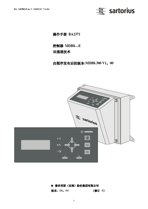
操作手册 BA2371控制器 MDB8—E双通道技术自程序发布后的版本:MDB8.300 V1。
00赛多利斯(亚琛)股份集团有限公司版本:06。
04 (修订 0)操作手册 BA — 2371前言本操作手册BA—2371 用于由一个type-MDB8—E控制器和一个探测线圈组成的金属检测器。
所有的说明将按照它们的逻辑顺序来进行描述。
在探测线圈安装和调试的描述中包含了所有型号的探测线圈。
并行文件:●控制器MDB8—E (D 2371) 数据表,●相应探测线圈的技术数据表,●探测线圈的安装说明(BA-2000)。
在把探测线圈安装到使用位置之前,仔细研究下列说明:●探测线圈的安装说明书BA-2000和●相应探测线圈的技术数据表(特别是关于“无金属区MZ”的章节); 它们包含了所必需的信息.关于在金属探测皮带上焊接工作的注意事项!如果必须在传送装置的框架上或者在单独的探测线圈支架上执行焊接工作,必须先断开控制器的电源,并且在元件和探测线圈之间的连接电缆必须从两端上都要断开,以避免对电子仪器造成损害!此外还必须将皮带遮盖起来,以免焊珠对产品造成金属污染!目录页码A1完整情况检查 (5)A2贮存 (5)A3安装说明 (5)A4一个以上的金属探测器同时使用 (5)1.0探测线圈的安装说明 (6)2.0安装控制器 (9)2.1电气安装 (9)2.2屏蔽电缆 (9)3.0控制器和操作员终端 (10)3。
1操作员终端 (10)3.2液晶显示器 (10)3.3功能指示灯 (11)3.4功能键 (11)4。
0探测线圈调节的注意事项 (12)4。
1显示补偿情况 (12)4.2测算补偿 (12)4。
3调节探测线圈 (13)Type-MDB-D探测线圈 (13)5.0测试棒 (13)6。
0外部传感器的选择和电子仪器的调整 (13)6.1表 (14)7.0代码功能 (15)7.1水平 1(主菜单) (15)7。
2水平 2 代码号:11 (打印报告,例如,用于质量控制) (15)7.3水平 3 代码号:333 (打印报告,例如,用于质量控制) (15)7。
狄耐克管理中心机

第一章 产品介绍 (1)1. 产品外观 (1)1.2 基本功能 (1)1.3 技术参数 (1)1.4 产品执行标准 (2)第二章 主界面 (2)第三章 使用方法 (3)3.1 对讲通讯 (3)3.2 影像监视 (4)3.3 应用功能 (5)3.4 系统配置 (7)3.5 报警记录 (13)3.6 对讲记录 (14)第四章 Web设置 (14)附:触摸屏校正说明 (19)第五章 系统接线图 (20)第六章 管理中心机接线图 (21)第七章 安全注意事项 (22)1目录1.3 技术参数◇工作:◇额定功率:6W◇待机功耗:2.5W◇显示屏:9英寸显示屏◇分辨率:800*480◇工作温度:-10~+55℃◇相对湿度:20%~93%◇CPU主频:350MHz◇内存:DDR2 1Gbit X 2◇Flash:16Gbit◇支持最大SD卡容量:32G电压DC12V1.2 基本功能◇与室内分机双向通话;◇监视围墙机、单元门口机及二次门口机;◇具备录音留言、闹钟功能;◇可设置时间;◇多种铃声可选。
1.产品外观1012028~℃01主菜单:对讲通讯、影像监视、应用功能、系统配置、报警记录、对讲记录。
状态栏:网络状态、SIP注册。
状态栏说明:1.网络状态 :有网络连接时,图标常亮;2.SIP注册 :当SIP注册成功后,图标常亮。
◇《GA/T 72-2005 楼寓对讲系统及电控防盗门通用技术标准》◇《GA/T 678-2007 联网型可视对讲系统技术标准》1.4 产品执行标准子界面快捷方式说明:单击该图标,页面跳转至呼叫通讯界面。
单击该图标,页面跳转至视频监视界面。
单击该图标,页面跳转至应用功能界面。
单击该图标,页面跳转至系统配置界面。
单击该图标,页面跳转至记录查询界面。
单击该图标,页面返回至主界面。
输入用户号码(3位楼栋号+2位单元号+4位分机号);输入楼栋号后,再单击键盘上的 图标,否则将无法输入单元号。
同样,输入单元号后,再单击键盘上的 图标,否则将无法输入分机号。
爱达顿电子保护设备_HN系列微型电路断忍器_HN系列微型电路断忍器家用说明书

Miniature Circuit Breakers HN xPole Home sg03518_rDescription• H igh-quality miniature circuit brea-kers for commercial and residentialapplications• G uide for secure terminal connection• 3-position DIN rail clip, permits remo-val from existing busbar system• C omprehensive range of accessoriessuitable for subsequent installation• R ated currents up to 63 A• T ripping characteristics B, C• R ated breaking capacity 6 kA accor-ding to IEC/EN 60898-1Rated currentI n (A)TypeDesignationArticle No.Units perpackage6 kA, Characteristic Bsg02918_r6HN-B6/119481812/12010HN-B10/119481912/12013HN-B13/119482012/12016HN-B16/119482112/12020HN-B20/119482212/12025HN-B25/119482312/12032HN-B32/119482412/12040HN-B40/119482512/12050HN-B50/119482612/12063HN-B63/119482712/1201-polesg02718_r6HN-B6/1N1948386/6010HN-B10/1N1948396/6013HN-B13/1N1948406/6016HN-B16/1N1948416/6020HN-B20/1N1948426/6025HN-B25/1N1948436/6032HN-B32/1N1948446/6040HN-B40/1N1948456/6050HN-B50/1N1948466/6063HN-B63/1N1948476/601+N-polesg03118_r6HN-B6/21948586/6010HN-B10/21948596/6013HN-B13/21948606/6016HN-B16/21948616/6020HN-B20/21948626/6025HN-B25/21948636/6032HN-B32/21948646/6040HN-B40/21948656/6050HN-B50/21948666/6063HN-B63/21948676/602-polesg03418_r6HN-B6/31948784/4010HN-B10/31948794/4013HN-B13/31948804/4016HN-B16/31948814/4020HN-B20/31948824/4025HN-B25/31948834/4032HN-B32/31948844/4040HN-B40/31948854/4050HN-B50/31948864/4063HN-B63/31948874/403-poleMiniature Circuit Breakers HN xPole Home Rated currentI n (A)TypeDesignationArticle No.Units perpackage sg03618_r6HN-B6/3N1948983/3010HN-B10/3N1948993/3013HN-B13/3N1949003/3016HN-B16/3N1949013/3020HN-B20/3N1949023/3025HN-B25/3N1949033/3032HN-B32/3N1949043/3040HN-B40/3N1949053/3050HN-B50/3N1949063/3063HN-B63/3N1949073/303+N-pole6 kA, Characteristic Csg02918_r6HN-C6/119482812/12010HN-C10/119482912/12013HN-C13/119483012/12016HN-C16/119483112/12020HN-C20/119483212/12025HN-C25/119483312/12032HN-C32/119483412/12040HN-C40/119483512/12050HN-C50/119483612/12063HN-C63/119483712/1201-polesg02718_r6HN-C6/1N1948486/6010HN-C10/1N1948496/6013HN-C13/1N1948506/6016HN-C16/1N1948516/6020HN-C20/1N1948526/6025HN-C25/1N1948536/6032HN-C32/1N1948546/6040HN-C40/1N1948556/6050HN-C50/1N1948566/6063HN-C63/1N1948576/601+N-polesg03118_r6HN-C6/21948686/6010HN-C10/21948696/6013HN-C13/21948706/6016HN-C16/21948716/6020HN-C20/21948726/6025HN-C25/21948736/6032HN-C32/21948746/6040HN-C40/21948756/6050HN-C50/21948766/6063HN-C63/21948776/602-poleRated currentI n (A)TypeDesignationArticle No.Units perpackage sg03418_r6HN-C6/31948884/4010HN-C10/31948894/4013HN-C13/31948904/4016HN-C16/31948914/4020HN-C20/31948924/4025HN-C25/31948934/4032HN-C32/31948944/4040HN-C40/31948954/4050HN-C50/31948964/4063HN-C63/31948974/403-polesg03618_r6HN-C6/3N1949083/3010HN-C10/3N1949093/3013HN-C13/3N1949103/3016HN-C16/3N1949113/3020HN-C20/3N1949123/3025HN-C25/3N1949133/3032HN-C32/3N1949143/3040HN-C40/3N1949153/3050HN-C50/3N1949163/3063HN-C63/3N1949173/303+N-poleMiniature Circuit Breakers HN xPole Home - T echnical DataSpecifi cations | Miniature Circuit Breakers HNDescription• H igh selectivity between MCB and back-up fuse due to low let-throughenergy• Compatible with standard busbar• T win-purpose terminal (lift/open-mouthed) above and below• B usbar positioning optionally above or below• M eets the requirements of insulation co-ordination, distance between con-tacts ≥ 4 mm, for secure isolation• S uitable for applications up to 48 V DCAccessories:Auxiliary switch for subsequent installation ZP-IHK286052ZP-WHK286053 Tripping signal switch for subsequent installation ZP-NHK248437 Remote control and automatic switching device Z-FW/LP248296 Shunt trip release ZP-ASA/..248438, 248439 Undervoltage release Z-USA/..248288-248291 Compact enclosure KLV-TC-2276240KLV-TC-4276241 Additional terminal 35 mm2Z-HA-EK/35263960 Switching interlock Z-IS/SPE-1TE274418Technical DataHNElectricalDesign according toCurrent test marks as printed onto the deviceIEC/EN 60898-1Rated voltage Un AC: 230/400 VDC: 48 V (per pole, max. 2 poles)Rated frequency50/60 HzRated breaking capacity according to IEC/EN 60898-1Icn 6 kACharacteristic B, CBack-up fuse max. 100 A gL Selectivity class3Rated impulse withstand voltage Uimp 4 kV (1.2/50 μs)Enduranceelectrical components≥ 10,000 switching operationsmechanical components≥ 20,000 switching operationsLine voltage connection at will (above/below)Minimal voltage12 V AC/DCMechanicalFrame size45 mmDevice height80 mmDevice width17.5 mm per pole (1MU)Mounting quick fastening with 3 lock-in positions on DIN rail IEC/EN 60715 Degree of protection IP20Upper and lower terminals open mouthed/lift terminalsTerminal protection fi nger and hand touch safe, DGUV VS3, EN 50274Terminal capacity1-25 mm2Terminal torque2-2.4 NmBusbar thickness 0.8 - 2 mmMounting independent of positionClimatic conditions Acc. to IEC 68-2 (25...55°C / 90...95% RH)Connection diagramsDimensions (mm)1P2P3P+N1P+N3P1-pole1+N-pole2-pole3-pole3+N-poleTripping Characteristics (IEC/EN 60898-1)Quick-acting (B), slow (C)Tripping characteristic BTripping characteristic CTRIPPING CURRENTTRIPPING CURRENTEffect of the Ambient Temperature on Thermal Tripping Behaviour Load Capacity of Series Connected Miniature Circuit BreakersAdjusted rated current values according to the ambient temperatureNumber of devices (n) 1-poleL o a d c a p a c i t y f a c t o r K NMiniature Circuit Breakers HN xPole Home - T echnical Data Let-through Energy HNLet-through Energy HN, Characteristic B, 1-poleLet-through Energy HN, Characteristic C, 1-pole500300500100015002000300040005000600070001000015000800090004009007008006001500100030002000500040002000090007000100008000600015000300005000060000400007000080000prospektiver Kurzschlussstrom [A]D u r c h l a s s e n e r g i e I t [A s e c ]22500300500100015002000300040005000600070001000015000800090004009007008006001500100030002000500040002000090007000100008000600015000300005000060000400007000080000prospektiver Kurzschlussstrom [A]D u r c h l a s s e n e r g i e I t [A s e c ]22Prospective short-circuit current [A]L e t t h r o u g h e n e r g y I 2t [A 2 s e c ]Prospective short-circuit current [A]L e t t h r o u g h e n e r g y I 2t [A 2 s e c ]Effect of Power FrequencyEffect of power frequency on the tripping behaviour I MA of the quick releasePower frequency f [Hz]162/35060100200300400I MA (f)/I MA (50 Hz) [%]91100101106115134141Short Circuit Selectivity HN towards DII-DIV fuse linkIn case of short circuit, there is selectivity between the miniature circuit breakers HN and the upstream fuses up to the specifi ed values of the selectivity limit current I s [kA] (i. e. in case of short-circuit currents I ks under I s only the MCB will trip, in case of short circuit currents above this value both protective devices will respond).*) basically in accordance with EN 60898-1 D.5.2.bShort circuit selectivity Characteristic B towards fuse link DII-DIV *)Short circuit selectivity Characteristic C towards fuse link DII-DIV *)Towards D01-D03 fuse linkShort circuit selectivity Characteristic B towards fuse link D01-D03*)Short circuit selectivity Characteristic C towards fuse link D01-D03*)Short circuit selectivity Characteristic B towards fuse link NH-00*)Short circuit selectivity Characteristic C towards fuse link NH-00*)1) Selectivity limit current I s under 0.5 kA 2)S electivity limit current I s = rated breaking capacity I cn of the MCB Darker areas: no selectivityTowards DII-DIV fuse linkTowards NH-00 fuse linkHN DII-DIV gL/gGHN DII-DIV gL/gGHN D01-D03 gL/gGHN D01-D03 gL/gGHN NH-00 gL/gG I n [A]1620253235405063801001251601)1)2)2)2)2)HN NH-00 gL/gG I n [A]1620253235405063801001251601)1)2)2)2)。
狄耐克AB-6A-401_402产品使用手册(V3[1].0)80455
![狄耐克AB-6A-401_402产品使用手册(V3[1].0)80455](https://img.taocdn.com/s3/m/b8922ada7e21af45b207a882.png)
目录一系统概述 (01)二系统操作 (04)三系统编程 (11)四系统配置及选材 (22)五系统原理图 (25)六系统连线示意图 (31)七安装调试 (35)八系统各部件的安装说明 (37)九其它事项 (37)版本:备注:本手册中所提及的终端设备(门口机、分机、管理机、围墙机),除特别说明外,主要是以可视系统AB-6A-402的设备为主。
一、系统概述AB-6A-402楼宇对讲系统是采用单片机微电脑控制技术,数位总线传输技术而设计的小区联网可视对讲系统。
系统数据传输距离可达5000米(需加中继器),防雷抗干扰,可实现大型小区的系统联网。
AB-6A-401楼宇对讲系统是非可视系统,除无视频外,其余性能与AB-6A-402系统相同。
两种系统主要适用于高楼大厦房型。
整个系统由门口主机(带联网功能)、室内分机、楼层交换机、主机电源、管理中心、管理中心电源、多门选择器、围墙机、信号中继器以及联网交换机等设备构成。
(见下表)◇编码门口主机AB-402D长×宽×厚(mm)外形尺寸:316×136×56开孔尺寸:280×114×34◇可视室内分机长×宽×厚(mm)外形尺寸:220×205×65(AB-402M)235×188×50(AB-402MQ)◇楼层交换机(AB-402A,AB-402B)长×宽×厚(mm)外形尺寸:126*150*40◇主机电源/交换机电源/管理中心电源(UPS-DP/UPS-P/UPS-CP)长×宽×厚(mm)外形尺寸:190×180×73◇管理中心(AB-602C)长×宽×厚(mm)外形尺寸:430×260×55 mm二、系统操作(一)门口机(402D)与用户分机通话1.来访者键入用户分机号码,若号码正确,则门口机发出悦耳的回铃声,呼叫开始。
狄耐克ABA产品使用手册V

目录一系统概述 (01)二系统操作 (04)三系统编程 (11)四系统配置及选材 (22)五系统原理图 (25)六系统连线示意图 (31)七安装调试 (35)八系统各部件的安装说明 (37)九其它事项 (37)版本:V3.0 备注:本手册中所提及的终端设备(门口机、分机、管理机、围墙机),除特别说明外,主要是以可视系统AB-6A-402的设备为主。
一、系统概述AB-6A-402楼宇对讲系统是采用单片机微电脑控制技术,数位总线传输技术而设计的小区联网可视对讲系统。
系统数据传输距离可达5000米(需加中继器),防雷抗干扰,可实现大型小区的系统联网。
AB-6A-401楼宇对讲系统是非可视系统,除无视频外,其余性能与AB-6A-402系统相同。
两种系统主要适用于高楼大厦房型。
整个系统由门口主机(带联网功能)、室内分机、楼层交换机、主机电源、管理中心、管理中心电源、多门选择器、围墙机、信号中继器以及联网交换机等设备构成。
(见下表)◇编码门口主机AB-402D长×宽×厚(mm)外形尺寸:316×136×56开孔尺寸:280×114×34◇可视室内分机长×宽×厚(mm)外形尺寸:220×205×65(AB-402M)235×188×50(AB-402MQ)◇楼层交换机(AB-402A,AB-402B)长×宽×厚(mm)外形尺寸:126*150*40◇主机电源/交换机电源/管理中心电源(UPS-DP/UPS-P/UPS-CP)长×宽×厚(mm)外形尺寸:190×180×73◇管理中心(AB-602C)长×宽×厚(mm)外形尺寸:430×260×55mm二、系统操作(一)门口机(402D)与用户分机通话1.来访者键入用户分机号码,若号码正确,则门口机发出悦耳的回铃声,呼叫开始。
GC4145 产品说明书(中文版)
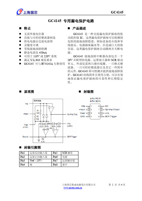
10 mV
0
3
50
上海国芯集成电路设计有限公司
第 2 页 共4页
上海国芯
典型应用
GC4145
双线 120V AC 插座模式典型应用
上海国芯集成电路设计有限公司
第 3 页 共4页
上海国芯
GC4145
三线 120V AC 插座模式的典型应用
500
uA
-3.0 0.5 +3.0 -5.0 0.5 +5.0 mV
6.8 7.2 8.1
6.5
7.2 8.3
V
-9.5 -11.2 -13.5
-9 -11.2 -14
650
uA
1.0
mA
1.0 1.8
MHz
10
Kohm
10
Kohm
3.5 4.7 5.9 Kohm
1.5 2.8
V
1.3 2.8
1
上海国芯集成电路设计有限公司
第 1 页 共4页
上海国芯
GC4145
极限参数
参数 电源电流 内部功耗 存储温度 工作温度
结温 DIP 60 秒
无铅焊接温度 SOIC 10 秒
最小
-65 -35
最大 18 500 +150 +85 +125 300 260
单位 mA mW ℃ ℃ ℃ ℃ ℃
流器、一只可控硅整流器以及其它一些简单
的元件。GC4145 即可检测并提供接地故障保
护。GC4145 结构简单且使用方便,可以有效
地保证漏电保护插座的可靠性和长期稳定
性。
原理图
封装图
封装引脚图
Pin1 运放反向输入端 Pin2 运放正向输入端 Pin3 Vref(13V) Pin4 地
安定宝4140安装手册

4140XMPT2防盗控制/通讯主机87防区 8个子系统 时间管理功能 16个继电器输出 128个使用者密码 224起事件记录ADEMCO 安定宝前言感谢您选用安定宝4140XMPT2防盗控制/通讯主机,希望我们先进的防盗系统会给您的生活、工作带来安全与方便!本安装编程指南适用于首次购买安装及曾使用过4140XMPT2防盗控制/通讯主机的安装工程人员。
本指南分五部分:安装说明、编程说明、系统操作与测试、安装例子与排错指南。
第一章安装说明包含对防盗系统原理、系统结构的描述。
使您对防盗系统基本概念及4140XMPT2主机的功能有一个初步了解。
第二章编程说明包含防盗系统操作原理、编程方法的描述。
详细说明每一个编程步骤,实现每一个功能的方法。
第三章系统操作与测试详细说明。
第四章安装例子分基础安装与扩充安装。
第五章排错指南针对一些常见故障提出改正方法。
目录前言 (I)目录 (II)第一章安装说明 (1)一.4140XMPT2主机系统结构。
(1)二.4140XMPT2主机性能说明。
(4)第二章编程说明 (6)一.防区类型 (6)二.布防方式与防区类型之关系: (7)三.编程概述: (7)编程预备知识: (8)四.编程模式编程说明: (9)1。
子系统部分选择功能(表格编程) (10)2。
#93菜单编程(菜单模式) (12)3。
控制选择功能(表格编程) (19)4。
防区选择功能(表格编程) (20)5。
无线部分选择功能(表格编程) (20)6。
通讯器选择功能 (21)7。
时间表与继电器输出选择功能: (24)8。
遥控编程选择功能(表格编程) (25)9。
事件记录选择功能(表格编程) (25)五.操作编程: (26)1。
时间管理编程: (26)2。
密码编程 (35)第三章系统操作与测试 (36)一。
键盘操作 (36)二。
测试系统 (38)第四章安装编程实例 (38)一.基础安装编程例子: (39)二.扩充功能安装编程例子: (40)第五章排错指南 (41)附页一:安装电路图 (45)附页二:通讯格式预设表 ............................................................................. 错误!未定义书签。
狄耐克
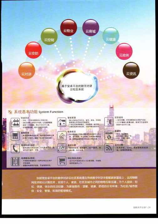
囝 多媒体 Mp3、 Mp4播 放 : 数 码 相 框、待机 广告 时 间 、 日期、闹 钟: 天气预报。
圈 电话对讲(选配) · 独 有 的 电话对讲功能,可 利用室内任电 话机进行 接听、开锁。
囫 系统设置 触 摸 屏 校 准、亮度调节、 对比廑调节、密 码设置、铃声设置 ,
国 远程控制 可 用 手 机、ipad、电脑登陆系统后 台,远程控制家电
1接收信息,并有信息灯提示。2系统预留二次门口机接口。可监视二次门口机和单元门口主机。3有报警防区接口,可 以连接8个有线防区(可外接辖接模块,实现无线安防报警)。4分机有键盘/钥匙/一键布撤防。5电话对讲功能(选 配).6电梯召唤功能(选配)。
魏 系 缓 功 糍 System Function
ej新承不
System Equipment Performance Is Interface
,|≮,
‘:誓戡一t-、j曩
1摄像头:彩 色CCD,红外夜视补偿功 能。2对讲功能 。可主动呼叫管理 中心与室内分机, 与其通话。3开 锁功能:密码开 ,,|ri t|”,,?£ 殳ZI 锁,非接触式感应 卡开锁;接受管理 中心及用户分机的遥 控开锁指令。4夜间操作:夜视背 光,方便来访者或 用户在夜间操
圆 可视对讲功能 圆 家庭 安防 报警功能 圈 备电应急功能 囵 电话 对讲 功能(选配
囤 ]禁开锁功能 国 阈 信息 接收 功能(选配 一 电 梯联 动控 制功能(选配
回 紧急求救功能 圆 图像 存储 功能(选配 圈 物业 综合 管理功能
@。6∥ 8蚴
System Equipment Performance Is Interface
卿
电 梯 联 动 f选 配 )
· 开 锁 联 动 电 梯降至一 层将访客送选 用户 所在楼 层: 便 捷 的 电 梯 预 约 功 能 , 节 省 候 梯 时 间。
狄耐克AB-6A-401_402产品使用手册

主机电源
UPS-DP
门口主机电源,带后备电池,DC12V输出。
交换机电
源
UPS-P
可供电8台AB-402A/B,室内分机由402A提供电源;
DC18V输出,配有备用电池。
管理中心
AB-602C
可呼叫小区内任一用户分机,并进行双向对讲;自动 识别门口主机、用户分机呼叫,发出不同的振铃声; 自动显示报警信息:楼号、层号、房号,醒目报警信 号灯提示;按FIFO原则自动记录最新32组报警信息; 管理9999个单元门口机,连接99个管理中心。
门口机开启电控锁,同时显示“oPEn”。否则回到待机状态。
2.刷卡开锁功能
将已在门口机中注册的ID卡距离门口机读卡头正上方5cm内的位 置,以每秒低于30c m的速度平行晃过,即可开锁。注意:在管理 中心与用户分机通话或分机监视门口机时,不影响门口机的刷卡 开锁功能。
四)用户分机呼叫管理中心 在摘机状态下按分机的呼叫键,开始呼叫管理中心。
五)可视分机监视门口机
在挂机状态下按分机的监视键,就能监视门口机。监视过程中再 一次按监视键,则关闭CRT结束监视。若在监视的状态下按下开 锁键,可开启大门电控锁并关闭CRT结束监视。
六)防拆功能(可选)
如果门口主机面盖被打开,门口主机立即向管理中心发送报警信 号,管理中心发出声光报警信号。
管理中心按警情键,管理中心显示图1-7,再按警情键,管理中心 显示图1-8,“******”代表门口主机的地址号码。
七)门磁信号检测功能(可选)
1.若系统处于忙状态,分机会发出听到3声“嘀”,并返回至待机 状态。
2.若系统处空闲状态,则分机从听筒中可听到回铃声,此时:
诺赛克说明书
楼宇可视对讲、家庭联网报警系统设计/安装/调试/使用说明书国际质量体系认证一.系统、产品分类及功能概述系统用线标准:各系统用线标准,是在电源线符合标准配置的情况下制定的:(参照:各系统用线标准及电源配置标准一览表“表3”)1.联网线用线标准:a.音频信号线:采用rvvp3*1.0mm2铜芯屏蔽防水线;最大传输距离1800米。
b.视频线:采用syv75-5防水铜芯同轴电缆线;每隔600米使用一台视频放大器,最多用两台,最大传输距离1800米, 2.单元内系统用线标准:a.门口机到电源箱电源线:·距离<10米时,采用rvv0.5mm2铜芯线。
·距离<30米时,采用rvv1.0mm2铜芯线。
在sw61可视对讲系统中:·音频信号线:主线(4芯)+入户线(4芯)长度<80m(楼层前30米+6层+入户30米)时,采用rvv4*0.5 mm2 铜芯线。
·视频信号线:主线采用sywv75-5同轴铜芯电缆线,入户线可采用sywv75—3同轴铜芯电缆线·视频电源线:主线(2芯)+入户线(2芯)长度<80m(楼层前30米+6层+入户30米)时,采用rvv2*0.5mm2 铜芯线。
三. 产品安装与系统开通注意事项(一).产品安装注意事项:1.门口机的安装:门口机可以嵌装于门体上或使用暗装盒安装于墙体上;门口机在单元门上嵌装时,需向门厂提供开口尺寸,36型门口机可以正面和侧面固定;侧装时,使用专用铁片固定于单元门上;可视门口机摄像头距地高度应在1.5米左右,注意防雨,防潮,防阳光直射,安装牢固。
2.电源的安装:电源可安装于楼道、弱电箱或弱电井内,注意防水、防潮、防盗、要接地良好;电源箱上所带的白色平行线用于连接220v交流市电;后备电池采用6v×2免维护蓄电池,在无交流电时,系统可由后备电池进行供电。
3.室内机的安装:室内机安装时,用配置的安装螺丝把相应的室内机挂板固定于室内的适当位置,挂板要安装牢固,安装高度应在1.5米左右,注意固定室内机时勿使室内机变形。
AT9600 交流接地电阻测试仪用户手册说明书

用户手册User’s GuideRev.A2.0固件说明:适用于主程序Rev.A2.0及以上的版本AT9600交流接地电阻测试仪●交流电流输出范围5~40A●2%输出电流精度●50Hz或者60Hz频率可选●最大开路电压6VAC●测试电压范围0V~6VAC●电阻量程0~600mΩ●测试时间0~999.9s(可关闭)●RS232接口(兼容SCPI与MODBUS协议) ●Handler(PLC)接口●全触控操作Applent安柏®是常州安柏精密仪器有限公司的商标或注册商标。
常州安柏精密仪器有限公司Applent Instruments Ltd.江苏省常州市钟楼区宝龙61-3层电话:0519-********传真:0519-********销售服务电子邮件: sales@ 技术支持电子邮件:tech@©2005-2018Applent Instruments Inc.安全须知当你发现有以下不正常情形发生,请立即终止操作并断开电源线。
立刻与安柏科技销售部联系维修。
否则将会引起火灾或对操作者有潜在的触电危险。
●仪器操作异常。
●操作中仪器产生反常噪音、异味、烟或闪光。
●操作过程中,仪器产生高温或电击。
●电源线、电源开关或电源插座损坏。
●杂质或液体流入仪器。
安全信息为避免可能的电击和人身安全,请遵循以下指南进行操作。
免责声明用户在开始使用仪器前请仔细阅读以下安全信息,对于用户由于未遵守下列条款而造成的人身安全和财产损失,安柏科技将不承担任何责任。
仪器接地为防止电击危险,请连接好电源地线。
不可在爆炸性气体环境使用仪器不可在易燃易爆气体、蒸汽或多灰尘的环境下使用仪器。
在此类环境使用任何电子设备,都是对人身安全的冒险。
不可打开仪器外壳非专业维护人员不可打开仪器外壳,以试图维修仪器。
仪器在关机后一段时间内仍存在未释放干净的电荷,这可能对人身造成电击危险。
不可在有强烈磁场或者电场的地方使用该仪器,电磁脉冲会引起仪器故障产生火灾。
狄耐克智能交通全系列设备功能与参数
目 录一、 出入口收费管理系统 (2)21.1 视频免取卡收费管理系统 .....................................................................21.1.1 车牌识别一体机 .........................................................................81.1.2 出入口显示控制一体机 ...................................................................1.1.3 出入口道闸 ..............................................................................9121.1.4 出入口票箱 ..............................................................................131.1.5 车位计数器 ..............................................................................1.1.6 车辆检测器 ..............................................................................13141.1.7 补光灯 ..................................................................................二、 车位引导及反向寻车系统 (16)162.1 公共设备 ....................................................................................2.1.1 中央控制器 ..............................................................................16162.1.2 室内车位引导屏 .........................................................................172.1.3 室外总入口车位引导屏 ...................................................................2.2 视频车位引导及反向寻车系统 .................................................................18182.2.1 视频节点控制器 .........................................................................192.2.2 模拟视频车位探测器 .....................................................................2.2.3 数字视频车位探测器 .....................................................................19212.2.4 寻车缴费一体机 .........................................................................222.2.5 智能寻车终端机 .........................................................................232.3 超声波车位引导系统 .........................................................................232.3.1 超声波车位探测器 .......................................................................242.3.2 车位指标灯 ..............................................................................252.3.3 超声波节点控制器 .......................................................................262.3.4 无线超声波车位探测器 ...................................................................272.3.5 无超声波节点控制器 .....................................................................一、出入口收费管理系统1.1 视频免取卡收费管理系统1.1.1车牌识别一体机 系列 可升降车牌识别一体机型号TS-PB-CS201图片成品尺寸 404x164x132mm开孔尺寸主要特点 集成抓拍、识别、补光于一体;基本功能1、支持抓拍车牌识别;2、可直接控制道闸开关;3、支持图片、视频上传功能;4、支持白名单功能;扩展功能 可外接报警设备;技术参数 1、工作电压:AC220V ±15% 2、额定功率:15W 3、通讯方式:TCP/IP4、传感器类型:1/3" Progressive Scan CCD5、像素:140万6、最小照度:0.1Lux@(F1.2,AGC ON)7、快门:1/30秒至1/100,000秒 8、补光灯:外置3颗LED 补光灯 9、工作温度:-40~70℃ 10、相对湿度:≤95% 11、防护等级:IP66系列 低端车牌识别一体机型号TS-PB-CS202图片成品尺寸 1454x375x201mm开孔尺寸主要特点 集成车牌抓拍识别、点阵屏显示控制、补光于一体;基本功能 1、支持抓拍车牌识别; 2、可直接控制道闸开关; 3、支持图片、视频上传功能;4、支持白名单功能;5、支持显示屏金额提示功能;6、支持语音播报功能;7、支持外置补光功能;扩展功能 无技术参数 摄像机部分:1、供电电源:9~24V---2A2、功耗:小于10W3、图像传感器:1/3" CMOS4、图像分辨率:720P CIF4 CIF5、最低照度:0.1 Lux(标准)6、信噪比:>50db7、电子快门:1/1至1/10000秒,22档8、防护等级:IP669、图像压缩:H.264 JPEG显示控制部分:1、工作电压:AC220V±15%2、额定功率:26W3、通讯方式:TCP/IP4、工作温度:-40~70℃5、相对湿度:≤95%6、防护等级:IP54补光部分:1、工作电压: 220VAC 50/60Hz2、功率:12W3、照射距离:约5M-20M4、发光角度: 45°5、工作环境温度:-20度~+80度6、重量:0.5KG7、防护等级: IP65系列 高端车牌识别一体机(含车牌识别一体机、显示控制一体机、补光灯) 型号 TS-PB-CS203图片成品尺寸 368x310x1268mm 开孔尺寸主要特点 集成车牌抓拍识别、点阵屏显示控制、补光于一体;基本功能 1、支持抓拍车牌识别;2、可直接控制道闸开关;3、支持图片、视频上传功能;4、支持白名单功能;5、支持显示屏金额提示功能;6、支持语音播报功能;7、支持外置补光功能;扩展功能 根据需求显示控制部分可选配;技术参数 摄像机部分:1、 供电电源:9~24V---2A2、 功耗:小于10W3、 图像传感器:1/3" CMOS4、 图像分辨率:720P CIF4 CIF5、 最低照度:0.1 Lux(标准)6、 信噪比:>50db7、 电子快门:1/1至1/10000秒,22档8、 防护等级:IP669、 图像压缩:H.264 JPEG显示控制部分:1、工作电压:AC220V±15%2、额定功率:26W3、通讯方式:TCP/IP4、工作温度:-40~70℃5、相对湿度:≤95%6、防护等级:IP54补光部分:1、工作电压: 220VAC 50/60Hz2、功率:12W3、照射距离:约5M-20M4、发光角度: 45°5、工作环境温度:-20度~+80度6、重量:0.5KG7、防护等级: IP65系列 高端车牌识别一体机(含车牌识别一体机、补光灯) 型号 TS-PB-CS203图片成品尺寸 368x310x982mm 开孔尺寸主要特点 集成车牌抓拍识别、点阵屏显示控制、补光于一体;基本功能 1、 支持抓拍车牌识别;2、 可直接控制道闸开关;3、 支持图片、视频上传功能;4、 支持白名单功能;5、支持外置补光功能;扩展功能 根据需求显示控制部分可增加;技术参数 摄像机部分:1、供电电源:9~24V---2A2、功耗:小于10W3、图像传感器:1/3" CMOS4、图像分辨率:720P CIF4 CIF5、最低照度:0.1 Lux(标准)6、信噪比:>50db7、电子快门:1/1至1/10000秒,22档8、防护等级:IP669、图像压缩:H.264 JPEG补光部分:1、工作电压: 220VAC 50/60Hz2、功率:12W3、照射距离:约5M-20M4、发光角度: 45°5、工作环境温度:-20度~+80度6、重量:0.5KG7、防护等级: IP651.1.2 出入口显示控制一体机系列 显示控制一体机 型号 TS-PB-MP101图片成品尺寸 688x400x169mm 开孔尺寸主要特点 集显示、控制、语音功能为一体;基本功能 1、显示车场信息、实时时间、提示用语、车牌信息、剩余车位(入口)),出入场时间及收费金额和月租到期剩余天数(出口);2、语音播报欢迎信息(入口);扩展功能 控制道闸起落;技术参数 1、 工作电压:AC220V±15%2、 额定功率:26W3、 通讯方式:TCP/IP4、 工作温度:-40~70℃5、 相对湿度:≤95%6、 防护等级:IP541.1.3 出入口道闸系列 道闸(外购) 型号 TS-PB-DZ001图片成品尺寸 1000x350x295mm 开孔尺寸主要特点 1、停电手摇电机手轮起杆,来电自动复位2、曲臂连杆机芯结构,起落杆平稳3、无线遥控控制起杆、落杆和停止4、遇阻返回:落杆过程中遇到阻力,立即停止并起杆5、红外对射防砸(需配对射装置)6、支持地感防砸7、接停车场系统开、关控制信号)(要求为开关信号)8、红绿灯接口(220VAC,可外接小于40W灯泡)9、提供限位状态信号给停车场系统(输出COM/NO/NC)10、延时落杆功能基本功能 1. 控制起杆、落杆和停止扩展功能1. 红外对射防砸(需配对射装置)2. 红绿灯接口(220VAC,可外接小于40W灯泡)技术参数 1. 机型工作温度:-35~+60℃2. 电控箱工作温度:-35~+60℃3. 输入电压:220V±10% 50/60Hz4. 额定功率:80W,电容:9+9uF/450V5. 相对湿度:≤90%RH6. 遥控距离:空旷小于100米,≥30米系列 道闸(外购) 型号 TS-PB-DZ002图片成品尺寸380x330x1214mm 开孔尺寸主要特点 集车牌识别、道闸控制、显示控制于一体;基本功能 1、 抓拍出入口车牌;2、 通过显示屏显示相关信息;3、语音播报欢迎光临;4、 控制道闸起杆、落杆、停止;扩展功能 根据需求车牌识别部分可选配;技术参数 闸机部分:1、 机型工作温度:-35~+60℃2、 电控箱工作温度:-35~+60℃3、 输入电压:220V±10% 50/60Hz4、 额定功率:80W,电容:9+9uF/450V5、 相对湿度:≤90%RH6、 遥控距离:空旷小于100米,≥30米 摄像机部分:1、供电电源:9~24V---2A2、功耗:小于10W3、图像传感器:1/3" CMOS4、图像分辨率:720P CIF4 CIF5、最低照度:0.1 Lux(标准)6、信噪比:>50db7、电子快门:1/1至1/10000秒,22档8、防护等级:IP669、图像压缩:H.264 JPEG系列 道闸(外购) 型号 TS-PB-DZ00图片成品尺寸 380x330x998mm开孔尺寸主要特点无基本功能 控制道闸起杆、落杆、停止;扩展功能 1、 抓拍出入口车牌;2、 通过显示屏显示相关信息;3、 语音播报欢迎光临; 技术参数1、 机型工作温度:-35~+60℃2、 电控箱工作温度:-35~+60℃3、 输入电压:220V±10% 50/60Hz4、 额定功率:80W,电容:9+9uF/450V5、 相对湿度:≤90%RH6、遥控距离:空旷小于100米,≥30米1.1.4 出入口票箱 系列 型号图片成品尺寸 开孔尺寸主要特点 1. 基本功能 1. 扩展功能 1. 技术参数 1.1.1.5车位计数器系列 车位计数器 型号TS-PB-Q5900图片成品尺寸 280x237x70mm开孔尺寸主要特点基本功能 1. 配合车辆检测器实时检测各个车辆通道的车辆出入并统计2. 通过TCP/IP 将剩余车位数上传到车位引导软件3. 通过485通信在车位引导屏上实时显示剩余车位数扩展功能 无技术参数 1. 通信方式:TCP/IP,标准RJ-45接口 2. 工作电压:100-220VAC±10% 3. 额定功耗:3W4. 工作温度:-10~55℃5. 相对湿度:20%~93%6. 防护等级:IP517. 大气压力:86~106 KPa1.1.6 车辆检测器 系列 车辆检测器(外购)型号TS-PB-Q2103(单路)TS-PB-Q2203(双路)图片成品尺寸 78×40×108mm (长×宽×高,含底座) 100×70×118mm (长×宽×高、含底座) 开孔尺寸主要特点基本功能 1.通过地感线圈检测车辆信息,并输出开关量信号扩展功能 无技术参数1.工作电压: 220VAC +10%/-15%2.额定功耗:4.5W3.输出继电器:240V/5A AC4.工作温度:-20~+65℃5.存储温度:-40~+80℃6.工作频率:20KHz-170KHz7.灵敏度:三级可调8.反应时间:10ms9.存在时间:无限存在10.线圈电感量:50uH-1000uH(100uH-300uH)11.线圈连接:越近越好,最长不超过5米,每米至少双胶20次1.工作电压:230VAC±10%2.输出继电器:240V/10A AC,30V/10A DC3.工作温度:-25~+65℃4. 湿度:≤90%(无凝露)5.工作频率:20KHz-170KHz6.灵敏度:九级可调7.反应时间:10ms8. 线圈材质:综合实际工程中导线的机械强度、高低温抗老化、耐酸碱腐蚀等问题,建议采用1个平方毫米以上的特氟龙高温软导线,总电阻小于10欧姆。
狄耐克ABA-_精选0产品使用手册V精选0

目录一系统概述 (01)二系统操作 (04)三系统编程 (11)四系统配置及选材 (22)五系统原理图 (25)六系统连线示意图 (31)七安装调试 (35)八系统各部件的安装说明 (37)九其它事项 (37)版本:V3.0备注:本手册中所提及的终端设备(门口机、分机、管理机、围墙机),除特别说明外,主要是以可视系统AB-6A-402的设备为主。
一、系统概述AB-6A-402楼宇对讲系统是采用单片机微电脑控制技术,数位总线传输技术而设计的小区联网可视对讲系统。
系统数据传输距离可达5000米(需加中继器),防雷抗干扰,可实现大型小区的系统联网。
AB-6A-401楼宇对讲系统是非可视系统,除无视频外,其余性能与AB-6A-402系统相同。
两种系统主要适用于高楼大厦房型。
整个系统由门口主机(带联网功能)、室内分机、楼层交换机、主机电源、管理中心、管理中心电源、多门选◇编码门口主机AB-402D长×宽×厚(mm)外形尺寸:316×136×56开孔尺寸:280×114×34◇可视室内分机长×宽×厚(mm)外形尺寸:220×205×65(AB-402M)235×188×50(AB-402MQ)◇楼层交换机(AB-402A,AB-402B)长×宽×厚(mm)外形尺寸:126*150*40◇主机电源/交换机电源/管理中心电源(UPS-DP/UPS-P/UPS-CP)长×宽×厚(mm)外形尺寸:190×180×73◇管理中心(AB-602C)长×宽×厚(mm)外形尺寸:430×260×55mm二、系统操作(一)门口机(402D)与用户分机通话1.来访者键入用户分机号码,若号码正确,则门口机发出悦耳的回铃声,呼叫开始。
- 1、下载文档前请自行甄别文档内容的完整性,平台不提供额外的编辑、内容补充、找答案等附加服务。
- 2、"仅部分预览"的文档,不可在线预览部分如存在完整性等问题,可反馈申请退款(可完整预览的文档不适用该条件!)。
- 3、如文档侵犯您的权益,请联系客服反馈,我们会尽快为您处理(人工客服工作时间:9:00-18:30)。
目录一系统概述………………………………………二系统制作………………………………………三系统编程………………………………………四系统配置及选材………………………………五系统原理图……………………………………六系统连线示意图………………………………七安装调试………………………………………八系统各部件的安装说明………………………九其它事项………………………………………版本:备注:本手册中所提及的终端设备(门口机、分机、管理机、围墙机),除特别说明外,主要是以可视系统的设备为主。
一、系统概述楼宇对讲系统是采用单片机微电脑控制技术,数位总线传输技术而设计的小区联网可视对讲系统。
系统数据传输距离可达米(需加中继器),防雷抗干扰,可实现大型小区的系统联网。
楼宇对讲系统是非可视系统,除无视频外,其余性能与系统相同。
两种系统主要适用于高楼大厦房型。
整个系统由门口主机(带联网功能)、室内分机、楼层交换机、主机电源、管理中心、管理中心电源、多门选择器、围墙机、信号中继器以及联网交换机等设备构成。
(见下表)◇编码门口主机长×宽×厚()外形尺寸:××开孔尺寸:××◇可视室内分机长×宽×厚()外形尺寸:××()××()◇楼层交换机(,)长×宽×厚()外形尺寸:**◇主机电源交换机电源管理中心电源()长×宽×厚()外形尺寸:××◇管理中心()长×宽×厚()外形尺寸:××二、系统制作(一)门口机()与用户分机通话.来访者键入用户分机号码,若号码正确,则门口机发出悦耳的回铃声,呼叫开始。
若号码不对或该分机不存在,则经过短暂等待后,门口机将显示“”,然后返回至待机状态。
.若呼叫有效,分机发出悦耳的振铃声,同时来访者的影像亦将出现在可视分机的显示屏上。
此时用户摘机,可与来访者通话。
.在通话中,用户可按开锁键,打开相应门的电控锁。
.在呼叫或通话过程中,门口机上的“*”键被按下,则门口机当前的呼叫或通话被取消,返回到待机状态。
.若呼叫进度超过秒,用户仍未摘机,系统放弃本次呼叫,返回到待机状态。
.当通话进度超过秒,系统自动切断通话。
.以下情况,门口机处于忙状态:当管理中心与用户分机通话时,门口机显示屏显示“”。
当分机监视门口机时,门口机显示屏显示“”。
(二)门口机呼叫管理中心在待机状态下,按下门口机键盘上的“*”键:.若管理中心忙,则门口机显示“”并返回至待机状态。
.若管理中心不忙,门口机将显示“”,并打开送出视频信号,同时发出回铃声。
管理中心振铃,显示门口机的编号“****”,并显示该门口机影像。
此时,值班人员可摘机,即可与门口机进行通话,通话限时为秒。
.在呼叫或通话中,若门口机的“*”键被按下,则放弃本次呼叫。
.通话状态下按下管理中心的开锁键,则相应门的电控锁将被打开,同时管理中心会发出一声“嘀”的开锁确认音,门口机显示“”,并发出一声“嘀”。
(三)密码开锁和刷卡开锁组公共密码开锁门口机待机状态,按“”键,门口机将显示“”,再按“”键,门口机显示“”,此时,输入任意一组公共密码,若密码正确,门口机开启电控锁,同时显示“”。
否则回到待机状态。
.刷卡开锁功能将已在门口机中注册的卡距离门口机读卡头正上方内的位置,以每秒低于的速度平行晃过,即可开锁。
注意:在管理中心与用户分机通话或分机监视门口机时,不影响门口机的刷卡开锁功能。
(四)用户分机呼叫管理中心在摘机状态下按分机的呼叫键,开始呼叫管理中心。
.若系统处于忙状态,分机会发出听到声“嘀”,并返回至待机状态。
.若系统处空闲状态,则分机从听筒中可听到回铃声,此时:.若分机挂机,则放弃呼叫。
.若管理中心摘机则进入通话制作。
.若秒后管理中心仍未摘机,则系统自动切断,放弃本次呼叫。
.紧急报警功能:挂机状态按下呼叫键超过秒,可实现紧急报警。
(五)可视分机监视门口机在挂机状态下按分机的监视键,就能监视门口机。
监视过程中再一次按监视键,则关闭结束监视。
若在监视的状态下按下开锁键,可开启大门电控锁并关闭结束监视。
(六)防拆功能(可选)如果门口主机面盖被打开,门口主机立即向管理中心发送报警信号,管理中心发出声光报警信号。
管理中心按警情键,管理中心显示图,再按警情键,管理中心显示图,“******”代表门口主机的地址号码。
(七)门磁信号检测功能(可选)如果主机所连接的大门,打开进度超过秒,则主机向管理中心发送报警信号,管理中心发出声光报警信号。
管理中心按警情键,管理中心显示图,再按警情键,管中心显示图,“******”代表门口主机的地址号码。
门打开:门磁信号与地线断路门关闭:门磁信号与地线短路(八)管理中心制作说明.管理中心呼叫用户分机管理中心可通过键盘输入“门口机号分机号”或通过“呼叫查询速拨”的方式呼叫任何一台用户分机。
.在待机状态下摘机,液晶背光灯亮(图),此时,可依次输入门口机号、分机号(图),再按“”键,发送呼叫号码(图)(也可在挂机状态下输入门口机号、分机号后提起手柄,自动发送呼叫号码)。
若该号码正确,则被呼叫分机开始振铃,管理中心发出回铃声,等待分机摘机,分机在要求进度内(秒)摘机,即可进入通话状态(图)。
在输入数字过程中,按“*”键或挂机将返回到待机状态。
..管理中心之间通话.在待机状态下摘机,液晶背光灯亮,此时按“”键,管理中心显示如图,输入两位管理中心号码,再按“”键,发送呼叫指令(也可在挂机状态下按“”键,输入两位管理中心号码后提起手柄,自动发送呼叫指令),开始呼叫另一台管理中心,若被叫管理中心摘机,则开始通话。
..监视门口机.输入门口机编号(最大位),按监视键显示如图。
在监视过程中,再按一次监视键或“*”键,即可取消监视。
. .。
若连接不上门口机则显示“通信不对”。
.若输入门口机编号后,秒仍未按“监视”键,自动转入待机状态。
.查询报警信息.待机状态下,按警情键,管理机将显示如图,再按警情键,依次显示报警详细信息如图。
警情:“”,如有警情则显示“”,第一位“”代表紧急防区。
第二位“”代表小时防区。
第三位“”代表延时防区。
依此类推。
...待机状态下,按未接键,管理机将显示图,再按未接键,依次显示未接详细信息图。
. ..在摘机状态下显示屏背光灯常亮,挂机一段进度后熄灭。
.若有未查询报警信息如图,则显示屏闪动。
若有未查询呼叫未接如图,则在挂机下显示屏闪动。
..显示“通信不对”.输入号码不对或线路故障.制作被中断或被叫方无回应.显示“电控锁已开”表示已开启门口机的电控锁.显示如图,表示门口机呼叫管理中心显示如图,表示用户机呼叫管理中心..有未查询报警提示-短“嘀嘀”声(七)围墙机制作说明(请参考门口机制作说明).围墙机呼叫分机时,需输入分机所在的门号和分机号码,其它与门口机一样。
.围墙机呼叫管理中心与门口机一样。
.围墙机也可刷卡开锁和公共密码开锁。
三、系统编程●门口主机()编程(一)门口机设置菜单:系统配置.本机号码.显示长度.显示模式.主副配置密码管理.工程密码.公共密码.密码复位卡管理.卡号注册.刷卡注册.删除卡号.查询卡号.删除全部系统设置.设置分机.设交换机①设置端口号码②保留③删除端口号码.设信息器①注册主机号②注册分机号③删除所有分机号码.铃声选择(可选)①普通模式②录音模式(二)门口机编程制作:按住“”键秒,主机显示“”,输入位超级密码或工程密码(初始密码为),主机显示“”。
在“”状态下可进行以下分菜单的编程设置:(一般情况下,“*”为退出键,“”键为确认键)按“”键进入系统配置菜单,主机显示“”,进行如下设置:.本机号码按“”键门口机显示“ ****”,输入位门口机号,按“”键确认,门口机显示“****”,“****”为新输入的门口机号。
按“*”键可退出此菜单,并进入系统配置菜单。
.显示长度按“”键门口机显示“ *”,“*”表示目前门口机的显示长度(即用户分机号的长度)。
根据系统要求输入(围墙机)数值,按“”键确认,门口机自动退出至系统配置菜单。
注意:本机号码(即门口机号)的位数与此菜单中的显示长度之和不得超过。
.显示模式此菜单用于设置用户分机号的显示模式(英文或数字)。
按“”键门口机显示“”,输入位数字“”或“”(表示相应显示位置为数字显示方式,表示相应显示位置为英文显示方式)。
输入不对按“*”键或其它数字键取消,设置成功后自动返回系统配置菜单。
.主副配置设置主门口机或副门口机(为主门口机、为副门口机)。
按“”键,若门口机显示“”后退出至系统配置菜单则门口机设置为主门口机。
若门口机显示“”后退出至系统配置菜单则门口机设置为副门口机。
注意:用户分机只能监视主门口机。
主副门口机的号码可以相同。
同一梯位只能有一台主门口机。
管理中心不能监视副门口机。
按“”键进入密码管理菜单,主机显示“”,进行以下设置:.工程密码按“”键门口机显示“”,输入位新密码,显示“”,再重复输入位密码,若两次输入密码相同,门口机显示“”,密码修改完成。
若两次输入密码不同,则显示“”。
.公共密码按“”键门口机显示“”,按“”键门口机显示“****”(已输入的旧密码)或“”。
若在显示旧密码“****”的状态下输入位新密码,门口机显示“”,则输入的新密码覆盖前面所显示的旧密码。
连续按“”键,可连续查询已存入的公共密码。
若门口机显示“”,则表示当前存储位置尚未存入密码。
此时输入位新密码,门口机显示“”,并且将此位新密码存入当前位置。
.密码复位(此功能只适用于系统)按“”键进入卡管理菜单,主机显示“”,进行以下设置:.卡号注册按“”显示“”,直接输入卡卡号,如卡号为“,”,则先输入前三位“”,此时,显示“-----”,然后输入后位“”,再按“”键,显示“--”,此时若仅注册单张卡则再按一下“#”键确认。
若注册连续卡号,如“,,”,则输入卡的张数“”按“”确认,显示“”,表示“、、”张卡注册成功(注:一次最多能注册张)。
注册成功后显示“-----”可继续注册其他卡,若卡号前位一样,可直接输入卡卡号后位。
若卡卡号前位不一样,按“*”键返回显示“---”,输入前位再输入后位,按“”确认,重复以上制作可注册其他卡。
注:卡超过存储容量将显示。
注册连续卡时,若存储容量不足将无法输入,如存储容量只能再存张卡,在显示“--”时只能输入以下的数,若输入的数超过将重新显示“--”.刷卡注册按“”键门口机显示“”,将卡靠近门口主机读卡部位,此时门口机显示卡号“****”,表示卡已注册成功,重复此制作可注册其它卡。
若卡已注册过,门口机则显示“”。
.删除卡号按“”键门口机显示“”,输入要删除卡号,按“”键确认门口机显示“”,不对显示“”。
