意大利NEM公司液压锁部分
Poyam阀门介绍
Split Body Ball Valves
Floating mounted Trunnion mounted
Side Entry Ball Valves
Floating mounted
2. General Service Valves- Ball
GENERAL SERVICE VALVES- Ball
Idiazabal is just 1 hour’s drive from BILBAO (International Airport) and at these distances from other important places: 90 km east of Bilbao, 45 km south of San Sebastian, 70 km south of the French border
Check Valves
GENERAL SERVICE VALVES BALL
2. General Service Valves- Ball
GENERAL SERVICE VALVES- Ball
Designs
Top Entry Ball Valves
Floating mounted Trunnion mounted
• • Valve materials: All CASTING All Ball Valves (soft seat)
GENERAL SERVICE VALVES GATE, GLOBE & CHECK
1. General Service Valves - S,G &R
General Service Valves- Gate, Globe y Check
1.Introduction (POYAM in MCC)
国外机床先进结构的原理及功能分析
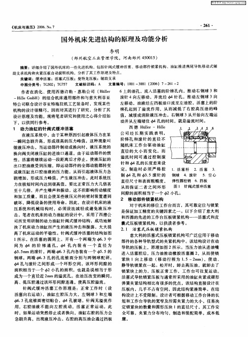
做液压冲击 。当运动部件 制动或换 向时 ,液压 系统 的 换向阀关闭液压缸的进油 口通道 。由于运动部件的惯 性 ,活塞将 继续 运动一段距 离后才停止 ,使液压 缸的 出口腔油液受到压缩 ,即运动部件的全部动能都转变 成液压缸 出 口腔油液 的压力能 ,从而引起液体压力急
剧增加 ,形成压力峰值 ,产生液压 冲击 。此时系统压 力在极短 时间内达 到很高值 ,要 比正 常压力大几倍甚 至十几倍 ,并产生 噪声 和振动 ,这不但影响传动精度 和加 工质量 ,而且会使某些液压元件 的密封装 置遭 到 破坏 ,降低设备 的使用寿命 。因此 ,在设计机床 的液 压系统和机 械 结构 时 ,必 须设 法减 轻 或避 免液 压 冲 击 。笔者在机床的动力油缸 的设计 中,采用了西德公 司所发 明研制 的动力油缸针 阀式缓冲结构 ,成功地解 决 了机床动力油缸所产生 的液压 冲击和振荡 ,大大提 高 了机床运动 的平稳性 。针 阀式缓 冲活塞 的结构如 图 l 所示 ,在活 塞 的圆周 上 ,开 有一 个两 端为 . 3中 间 为 的 阶 梯 通 孔 , 孔 内装 有 一 个 直 径 为 4 .m , 5 m的滚针 ,两端 . 孔 内各装 有一个 q . 3 3 b 5的 5 钢 球 ,两端 . 3孔 的孔底 锥 面分 别 与两钢 球 配研 。
西 德 Hie t r— Hl l l ie l
设计原理及功能 。现将 笔者研究和使用之心得介绍 如 下 ,以供 同行参考 。 1 动力油 缸 的针 阀式缓 冲活 塞 在液压 系统 中 ,由于某种原 因引起液体压力在某 瞬间急剧升高 ,形成很高 的压力 峰值 ,这种现象 叫
一
公司 经长期 实践 表 明, 阶梯孔 和 滚针 的直 径不
意大利的活塞 式压板 锁紧机构可广泛应用于移动 部件的各种导轨型式的夹紧机构 中。该结构设计在动
挖掘机的液压系统设计与仿真计算说明书
摘要液压系统是目前挖掘机必不可少的组成部分,液压系统通过改变压强增大作用力来工作。
完整的液压系统包括:动力元件、执行元件、控制元件、辅助元件和液压油。
挖掘机的工作环境复杂多变,所以对于液压系统提出了很高的设计要求。
在搜集国内外液压系统相关资料的基础上,了解其发展过程,分析总结了液压挖掘机的技术发展动态,了解液压挖掘机液压系统的结构。
液压挖掘机由多个系统组成,包括液压系统、传动系统、操纵系统、发动机、油箱、转台等等。
本设计从分析液压挖掘机的基本原理出发,分析了液压挖掘机的结构,工作原理,油路控制,从而确定了液压挖掘液压系统的设计方案,并对所设计的液压系统进行了模型建立,到模型仿真,以确保所设计的液压系统的安全可靠,结构优良,价格经济。
本设计还细致分析了液压挖掘机的液压元件的选型,与设计计算,采用的CAD设计出了液压挖掘机的原理图,运用了simulationx进行的模型建立与仿真,确保了所建立的模型的正确性。
运用simulationx建立系统模型的与仿真这是本设计的一大特点。
关键词:液压系统液压挖掘机液压元件SummaryThe hydraulic system is an integral part of excavator, hydraulic system is to work by changing the pressure to increase the force. The intact hydraulic system is including: power components, the implementation of components, control components, auxiliary components and hydraulic oil. The excavator working environment is complex and changeable, so it is very high requirement of design to hydraulic system.In the collection of domestic and foreign hydraulic system on the basis of relevant information, understanding of its development process, analyzed and summarized the technology development of hydraulic excavator. Understand hydraulic excavator hydraulic system structure. Hydraulic excavator is composed of a plurality of system components, including the hydraulic system, drive system, control system, engine, fuel tank, table and so on. My design focused on the design of hydraulic system of excavator. Keywords: hydraulic system excavatory目录第一章绪论 (1)1.1 挖掘机的简介 (1)1.2 国内外的发展趋势 (2)1.2.1 国内发展趋势 (2)1.2.2 国外发展趋势 (2)1.3 本设计的主要内容 (3)1.3.1 了解液压挖掘机液压系统的结构 (3)1.3.2 挖掘机液压系统设计要求 (3)第二章液压挖掘机结构与工作原理 (5)2.1 液压挖掘机的系统组成 (5)2.1.1 动力系统 (5)2.1.2 液压系统 (5)2.1.3 机械系统 (5)2.1.4 控制系统 (6)2.2 液压挖掘机传动原理 (6)第三章挖掘机工况分析以及液压系统设计方案的的确定 (7)3.1 液压系统的工况分析 (7)3.1.1 挖掘工况分析 (8)3.2 挖掘机液压系统的设计要求 (8)3.2.1 满斗举升回斗工况分析 (10)3.2.2 卸载工况分析 (10)3.2.3 空斗返回工况分析 (11)3.3 挖掘机液压系统的设计要求 (11)3.3.1 动力性要求 (11)3.3.2 操纵性要求 (11)3.3.3 节能性要求 (12)3.3.4 安全性要求 (12)3.3.5 其它性能要求 (12)3.4 液压系统方案拟订 (13)第四章液压系统的设计 (14)4.1 确定油缸所受的作用力 (14)4.1.1 铲斗油缸作用力的分析 (14)4.1.2 斗杆油缸作用的确定 (16)4.1.3 动臂油缸作用力分析 (18)4.2 各油缸尺寸的确定 (19)4.2.1 铲斗油缸工作压力的确定 (19)4.2.2 缸径D和油塞杠直径d的确定 (19)4.2.3 缸壁厚和外径的计算 (20)4.3 斗杆油缸尺寸的计算 (21)4.3.1 由铲斗油缸计算步骤知斗杆缸受力平衡 (21)4.3.2 缸壁厚和外径的计算 (21)4.4 动臂缸的尺寸计算 (21)4.4.1 由铲斗油缸计算步骤知动臂油缸受力平衡 (21)4.4.2 缸壁厚和外径的计算 (21)4.6 各液压缸和马达流量的确定 (23)4.6.1 每个缸的流量计算 (23)4.6.2 回转马达的流量的计算及选型 (23)4.6.3 行走马达的选用 (24)4.6.4 主回路液压泵的选择 (25)4.7 管路油管的选择 (25)4.7.1 油管内径的确定 (25)4.7.2 管接头的选择 (26)4.7.3 螺塞的选用 (26)4.8 液压油箱的确定 (26)4.8.1 液压系统的发热和升温的验算 (27)4.9 液压装置的结构设计 (27)4.9.1 阀集成款 (28)第五章挖掘机液压系统模型的建立与仿真 (29)5.1 关于仿真软件Simulationx (29)5.1.1 Simulationx的简介 (29)5.1.2 S在液压系统中的应用 (30)5.2在Simulationx中选取液压元器件 (30)5.2.1 液压元器件的选取 (30)5.2.2其他各种元件的选取 (34)5.3 挖掘机液压系统仿真模型的建立 (36)5.3.1草图的绘制 (37)5.3.2元器件参数的设置 (37)5.3.3仿真模式 (42)5.4 仿真的结果 (42)5.4.1液压泵的仿真曲线 (42)5.4.2内燃机的仿真曲线 (43)5.4.3控制铲斗缸的三位四通换向阀的仿真曲线 (43)5.4.4液压缸的仿真曲线 (44)5.4.5控制液压马达的三位四通阀的仿真曲线 (44)5.4.5回转马达的仿真曲线 (45)5.5挖掘臂的局部仿真 (45)5.5.1元件的参数设置 (46)结论 (48)参考文献 (49)致谢 (50)第一章绪论作为具有多功能这一特性的机械,液压挖掘机被广泛使用于交通运输,矿山采掘和电力工程等施工中,挖掘机减轻了作业难度,提高作业效率,加快建设速度以及提高劳动生产率方面表现出十分显著的作用。
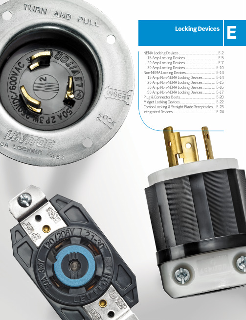
NEMA锁定设备产品参考文档说明书
Locking Devices E NEMA Locking Devices ................................................... E-215 Amp Locking Devices........................................... E-520 Amp Locking Devices........................................... E-730 Amp Locking Devices........................................ E-10Non-NEMA Locking Devices ...................................... E-1415 Amp Non-NEMA Locking Devices ................ E-1420 Amp Non-NEMA Locking Devices ................ E-1530 Amp Non-NEMA Locking Devices ................ E-1650 Amp Non-NEMA Locking Devices ................ E-17Plug & Connector Boots .............................................. E-20 Midget Locking Devices .............................................. E-22 Combo Locking & Straight Blade Receptacles ... E-23 Integrated Devices ........................................................ E-24NEMANEMA Locking DevicesLocking Devices for the Entire Spectrum of Industrial ApplicationsLeviton’s industrial grade locking devices are built to provide unparalleled quality and superior performance in the most severe industrial settings. Leviton combines the best materials available with superior production standards to produce a broad selection of locking devices of unmatched flexibility and dependability.Cleat on contactscuts oxidationwhen plug bladesenter contactsurfacesCombination #10-32 deepslotted/Phillips brassscrews withstand hightorquebody with radial gripping ridgecreates an ideal surfacefor gripping, turning and pullingidentifiesmaximumcord sizeallowed withstrain reliefinsertExternal cord clamp utilizes deep tripledrive steel screws that are backedout and positioned inside shroudedpockets. Accepts wire mesh gripsOne-piece, rivetless, .035" thickbrass contacts offer enlargedcontact surface areas, improvedconductivity, low resistance, lowheat and long lifeColor-codedterminalInternal wiring chambers isolate individualconductors to prevent flashover, arcing,transparent wiring chambersprovide a means of visualinspection of conductorsExposed ConnectorE-2Online catalog available at NEMAnEMA configuration,agency certifications anddevice rating are moldedon front of device tosolid brass bladesare fitted and heldDead front constructionprevents accidentalcontact with internal partskeyed to body foreasy assembly maximizing wire/clamp surface contactterminal identification letterson back cover ensure quick andaccurate terminationsuper tough nylonresists damagefrom severe impact,abrasion andchemicals Exposed PlugNEMALocking Flush ReceptaclesEngineered for maximum performance with a UL 94 V-O flammability rating.seam between front cover and back cover isfar from contact working areatriple combination mounting screws, multi-terminated design, accepts #8 to #14 solidor stranded conductorsMolded-in terminal identification lettersExternal nickel plated clamps accept #8 to #14 solidor stranded conductors for back and side wiringOversized #10 brass Phillips/robertson/straight slot drive terminal screwExtra thick .050" nickel-plated brass mounting strapstamped-in agency certificationsMolded-in amperage and voltage ratingnEMA configurationColor-coded voltage ratingstability ribsManufacturertriple combination head mounting screwsuni-body faceSampleReceptacles15A-125VL1-15P L1-15R Description Cat. No. Cat. No. Plugs and Connectors Plug Connector4560-IG Wired, 6" Green Ground LeadDuplex Flush Receptacle w/2 — 4702-IIR— — — —Hot Feeds and 1 NeutralReturn, Self Grounding,Back and Side WiredDuplex Flush Receptacle — 4703-IIR— — — —w/Split Feed – 2 Hot Feeds and2 Neutral Returns, SelfGrounding, Back and Side WiredSingle Flush Receptacle — 4710— 4560— 4760Single Flush Receptacle, — 4710-SS— — — —w/Short StrapSingle Flush Receptacle, — 4710-IG— 4560-IG— 4760-IGIsolated Ground231023112313L5-20PL5-20RL6-20P L6-20R L7-20P L7-20RDescription Cat. No. Cat. No. Cat. No. Cat. No.Cat. No. Cat. No.Plugs and Connectors Plug Connector Plug Connector Plug Connector Black & White ® 2311 2313 2321 2323 2331 2333 Nylon Body All Black 2311-B 2313-B — 2323-B — 2333 Nylon BodyYellow Nylon Body 2311-CY 2313-CY 2321-CY 2323-CY — — Power Indication™ 2311-PLC 2313-PLC 2321-PLC 2323-PLC 2331-PLC 2333-PLCBlack & White ®Nylon BodyPower Indication™ 2311-PLB 2313-PLB — — — — All Black Nylon BodyInlets and Outlets Inlet Outlet Inlet Outlet Inlet Outlet 7102-C241624112413Rating 20A-125/250V 20A-3Ø 250V 20A-3Ø 480V Flanged Device236523662375237623852386ReceptaclesV-O-Max ® Single Flush — 2360 — 2370 — 2380Receptacle3-Pole, 3-Wire Non-Grounding U R20A-125/250V, 3Ø 250V and 3Ø 480VRating20A-125/250V20A-3Ø 250V 20A-3Ø 480V NEMA3-Pole, 4-Wire Grounding U R23412516 L21-20P L21-20R L22-20P L22-20R L23-20P L23-20RDescription Cat. No. Cat. No. Cat. No. Cat. No. Cat. No. Cat. No.PlugsandConnectors Plug Connector Plug ConnectorPlug ConnectorBlack & White® Nylon Body 251125132521252325312533Inlets and Outlets Inlet Outlet Inlet Outlet Inlet OutletFlanged Device 251525162525252625452546ReceptaclesV-O-Max® Single — 2510— 2520— 2530Flush ReceptacleV-O-Max® Single Flush — 2510-IG— 2520-IG— 2530-IGReceptacle, Isolated GroundFor NEMA L24-20 see page E-826202621-B All Black Nylon BodyInlets and Outlets Inlet Outlet Inlet Outlet Inlet OutletFlanged Device 261526162625F2626F26352636ReceptaclesV-O-Max® Single — 2610— 2620— 2630Flush ReceptacleV-O-Max® Single Flush — 2610-IG— 2620-IG— 2630-IGReceptacle, Isolated Ground30A-480V AC and 600V ACDescription Cat. No. Cat. No. Cat. No. Cat. No. Plugs and Connectors Plug Connector Plug Connector Black & White® Nylon Body 2681268326912693 Inlets and Outlets Inlet Outlet Inlet Outlet Flanged Device 2685268626952696ReceptaclesV-O-Max® Single Flush — 2680— 2690ReceptacleAll Black Flush Mount —2710-B——Locking Receptacle271127102733273630A-3Ø 480V AC and 3Ø 600V ACDescriptionCat. No. Cat. No.Cat. No. Cat. No. Plugs and Connectors Plug Connector Plug ConnectorBlack & White ® Nylon Body 2731 2733 2741 2743 All Black2731-B 2733-B — — Inlets and Outlets Inlet Outlet Inlet OutletFlanged Device2735273627452746ReceptaclesV-O-Max ® Single — 2730 — 2740 Flush ReceptacleV-O-Max ® Single Flush — 2730-IG — 2740-IGL21-30P L21-30R L22-30P L22-30R L23-30P L23-30R Description Cat. No. Cat. No. Cat. No. Cat. No. Cat. No. Cat. No.PlugsandConnectors Plug Connector Plug ConnectorPlug Connector Black & White® Nylon Body 281128132821282328312833Inlets and Outlets Inlet Outlet Inlet Outlet Inlet Outlet Flanged Device 281528162825282628352836ReceptaclesV-O-Max® Single — 2810— 2820— 2830Flush ReceptacleV-O-Max® Single Flush — 2810-IG— 2820-IG— —Receptacle, Isolated Ground74113525-CLocking Flanged Inlet 3524-C —Locking Flanged Outlet — 3525-C Single Flush Receptacle—3520Single Flush Receptacle —7410-B*Black*Add (-G) for grounding devices3431-CLocking Connector —3433-C* Locking Flanged Inlet 3434-C —Locking Flanged Outlet — 3435-CSingle Flush Receptacle—3430**Add (-G) for grounding devices333033333431-C50A NON-NEMA | Black & White®50A Non-NEMA Locking DevicesIndustrial Grade Black & White® Locking Devices3765C3763CWallplates and CoversWeather-Resistant Flip Lid Cover for 50A ReceptaclesIP64 Rated—Includes Gasket and Screws7788-CR7770Yellow Lexan Gray MetalRating 50A-125/250V 50A-3Ø 250V 50A-3Ø 480VN on-N EMALocking Flanged Inlet CS6377— CS8275— CS8475—Single Locking Receptacle —CS6370— CS8269— CS8469Description Cat. No. Cat. No. Cat. No. Cat. No. Cat. No. Cat. No.Locking Plug CS6365C—CS8365C—CS8165C—Locking Connector —CS6364C—CS8364C—CS8164CLocking Flanged Inlet CS6375—CS8375CS8175—Single Locking Receptacle —CS6369— CS8369—CS81692-Pole, 3-Wire Grounding U RCs6364CCs8375 Wallplates and CoversWeather-Resistant Flip Lid Cover for 50A Receptacles7788-CR7770Non-NEMA 50A-125/250V, 3Ø 250V and 3Ø 480V50A NON-NEMA | Corrosion Resistant• Stainless steel shrouds on receptacles and plugs for corrosion resistance • Stainless steel receptacle mounting screws50A Corrosion Resistant Devices6370Cr(Front and Back)6361Cr6377Cr15A, 20A 30A, 50A | Locking Plug and Connector Boots Locking Plug and Connector BootsThermoplastic Elastomer Construction6017-L Y603260336034• Features triple seal action to protect locking plugs and connectors against dirt and moisture in harsh applications • Plug and connector boots available in black and high-visibility yellow• Fluted surface and grip-ring design provide a non-slip grip even in wet conditions • Backed by a limited lifetime warrantyU SCat. No. Plug Boot, Black6017-L Plug Boot, High-Visibility Yellow 6017-L Y Connector Boot, Black6018-LConnector Boot, High Visibility Yellow6018-L YU SCat. No. 4 & 5-Wire Plug Boot, Black6033 4 & 5-Wire Plug Boot, High-Visibility Yellow 6033-Y 4 & 5-Wire Connector Boot, Black60344 & 5-Wire Connector Boot, High Visibility Yellow6034-YU SCat. No. Plug Boot, Black, IP55 Rated 7715-CR Plug Boot, High Visibility Yellow, IP55 Rated 7715-CRY Connector Boot, Black, IP55 Rated 7717-CR Connector Boot, High Visibility Yellow, IP55 Rated 771-7CRY U SCat. No. 3-Wire Plug Boot, Black6031 3-Wire Plug Boot, High-Visibility Yellow 6031-Y 3-Wire Connector Boot, Black60323-Wire Connector Boot, High Visibility Yellow6032-YandAngle ML1-AP ML1-ACInlets and Outlets Inlet OutletML1-PML1-APML2-APML3-PML2ML2Description Cat. No. Cat. No.Plug Connector Locking ML2-P ML2-C Angle ML2-AP ML2-AC Inlets and Outlets Inlet OutletNylon Flange ML2-PBML2-PERRating 15A-125/250V 3-Pole, 3-Wire Non-Grounding U R15A-125/250V15A | Combination Locking and Straight Blade Combination Locking and Straight Blade Duplex Receptacles • Impact-resistant black thermoplastic nylon face and body• Smooth face does not collect dirt• Large, triple-wipe brass “T” contacts for superior contact and conductivity• Triple-combination terminal screws• Back and side wire options accept #10–#14 AWG stranded or solid wire• Backed by a limited 10-year warrantyL5-15R 5-15RDescription Cat. No.Duplex Combination Locking & Straight Blade Receptacle with Common Feed 47922 Hot Feeds, 1 Neutral Return 4794-1RSplit Feed — 2 Hot Feeds, 2 Neutral Returns 4795-2R4792 Wallplates and Covers15A-125VDescription Cat. No. Cat. No. Cat. No. Cat. No.Inlet Outlet Inlet OutletStandard Wire Wells 4716-CWP4715-CWP4586-CWP4585-CWP4715-CWP。
亿利达液压注塑机

螺杆的选用
双金属机筒、螺杆 在原料中添加玻璃纤维主要是用来提
高制品的强度, 但是玻纤及陶瓷粉末均有 较强的磨损性, 一般氮化机筒螺杆组件应 用於这种原料, 快则三个月就会有严重的 磨损,间隙增大, 无法生产出稳定的产品◦ 目前唯一的解决办法是采用双金属机筒, 配全硬的螺杆◦
螺杆的选用
双金属螺杆 耐磨、耐腐蚀 螺杆表面粗糙度差,造成 双,寿命氮化螺杆2倍以上 透明、热敏感、含玻璃纤维(比例不同) 国外双,价格,普通价格10配 国产,价格2~3倍 我们产品来自美国、意大利 塑胶部例子moto pc产品,产品稳定,无发黄问题 建议使用,减少因螺杆问题出现的各类损耗,料贵
结构参数: 长径比(L/D)螺杆牙部总长÷螺杆直径 压缩比:L/R=入料牙深÷计量牙深
螺杆的认识
螺杆结构参数对塑料制品的影响: L/D比太大: 会导致料停留时间过长,出现塑化过度,
制品变色,强度下降,对螺杆强度也有较大影响. L/D比不足: 会导致混炼不足,塑料未能达 到熔融
状态. 压缩比太大: 会导致剪切力过大,使温度升高及熔
剪切热太大; 选择大机台,注塑小产品
螺杆使用常见问题及原因
制品表面有黑点: 原料污染或带进杂质; 塑料颗粒大小不均匀; 熔胶筒组件有磨损或腐蚀; 熔胶筒组件配合处有死角导致集料分解; 螺杆表面光洁度不良,粘料炭化; 料斗是否干凈.
螺杆使用常见问题及原因
料筒升温: 背压太大; 螺杆转速太高; 有异物进入; 螺杆弯曲与料筒内壁磨擦或止逆环有磨擦; 螺杆结构尺寸设计不合理;
螺杆的选用
若客户以PC、PMMA、防火ABS料为主, 应选择单螺纹镀铬螺杆或单螺纹不锈钢螺 杆;
双向液压锁-F42双向液压锁
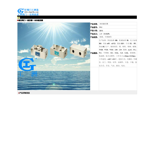
液压阀门>>液压锁>>双向液压锁产品详细信息其它阀系列价格供用户或设计院工程项目做预算电动二通阀价格底阀价格电动二通阀价格呼吸阀阻火器价格流量计价格水处理器价格橡胶接头价格一、阀门的选型步骤1.明确阀门在设备或装置中的用途,确定阀门的工作条件:适用介质、工作压力、工作温度等等。
2.确定与阀门连接管道的公称通径和连接方式:法兰、螺纹、焊接等。
3.确定操作阀门的方式:手动、电动、电磁、气动或液动、电气联动或电液联动等。
4.根据管线输送的介质、工作压力、工作温度确定所选阀门的壳体和内件的材料:灰铸铁、可锻铸铁、球墨铸铁、碳素钢、合金钢、不锈耐酸钢、铜合金等。
5.确定阀门的型式:闸阀、截止阀、球阀、蝶阀、节流阀、安全阀、减压阀、蒸汽疏水阀、等。
6.确定阀门的参数:对于自动阀门,根据不同需要先确定允许流阻、排放能力、背压等,再确定管道的公称通径和阀座孔的直径。
7.确定所选用阀门的几何参数:结构长度、法兰连接形式及尺寸、开启和关闭后阀门高度方向的尺寸、连接的螺栓孔尺寸和数量、整个阀门外型尺寸等。
8.利用现有的资料:阀门产品目录、阀门产品样本等选型适当的阀门产品。
二、阀门的选型依据1.所选用阀门的用途、使用工况条件和操纵控制方式。
2.工作介质的性质:工作压力、工作温度、腐蚀性能,是否含有固体颗粒,介质是否有毒,是否是易燃、易爆介质,介质的黏度等等。
3.对阀门流体特性的要求:流阻、排放能力、流量特性、密封等级等等。
4.安装尺寸和外形尺寸要求:公称通径、与管道的连接方式和连接尺寸、外形尺寸或重量限制等。
⑤对阀门产品的可靠性、使用寿命和电动装置的防爆性能等的附加要求。
(在选定参数时应注意:如果阀门要用于控制目的,必须确定如下额外参数:操作方法、最大和最小流量要求、正常流动的压力降、关闭时的压力降、阀门的最大和最小进口压力。
)根据上述选型阀门的依据和步骤,合理、正确地选型阀门时还必须对各种类型阀门的内部结构进行详细了解,以便能对优先选用的阀门做出正确的抉择。
液压系统说明书

第二章 液压系统
液压系统原理图如图 2.2.1-5 所示,在液压系统中有两个回路: 1) 系统控制回路
此回路属于高压回路,压力油从串联式双联齿轮泵的高压端输出,经过离合 器压力比例控制阀调节之后,推动离合器。
齿轮泵从下箱体抽取润滑油,并将其从齿轮泵高压口泵出,通过一过滤精度 为 10µ的系统过滤器;在齿轮泵高压出口处安装有泄压阀,压力设置为 1250psi, 当管路或者阀块堵塞并超过压力设定值时,安全阀即打开以保护齿轮泵;压力油 经过过滤器过滤后进入控制箱中的阀块,阀块安装有 RV 阀和 PCV 阀。RV 阀根 据高低压进行设定,用以限制离合器压力不高于设定值;PCV 用以精确控制 CST 离合器压力;经过比例阀控制后的压力油进入 CST 离合器中,推动离合器工作。 2) 润滑回路
括 G750、750、1000、1120、1500、1950、以及 2500。低压系统和高压系统之间结构和
原理相似,区别仅仅在于其工作压力以及相应元器件有所变化,如下表所示。
元器件名称
低压系统
高压系统
离合器压力变送器 PT-1 离合器压力表 PI-1 控制压力安全阀 PRV-1 系统压力安全阀 RV
K 型 CST 和 KR 型 CST 之间液压系统差异 K 型 CST 和 KR 型 CST 的液压系统结构基本相同,但是由于 KR 型 CST 多了一个
中间轴,轴承数量增多,需要更多的润滑支路,因此 KR 型 CST 润滑回路阀块有四路 分流支路。
手册编号# 61408351–Ver01
第 5 页 共 22 页
手册编号# 61408351–Ver01
第 1 页 共 22 页
第二章 液压系统
2. 液压系统
2.1 液压系统类型
森精机NMV5000操作手册
关于本手册 About this Manual
• 请将此手册置于显著标记位置,以便需要时备查。
• 若对本手册有任何疑问,请致电森精机服务部。
• 若本手册遗失或损坏,请致电森精机服务部或经销商。
• 若因机床改进而造成本手册内容变更,恕不另行通知。
• 保留所有权利:在没有获得森精机的书面同意之前,不允许 对本操作手册进行任何形式的复制。
操作手册 OPERATION MANUAL
适用机型 Applicable Model
NMV1500 DCG NMV3000 DCG NMV5000 DCG NMV8000 DCG/40
NMV8000 DCG/50
适用数控装置 Applicable NC Unit
MSX-701IV
MSX-711IV
在开始操作、维护或编程之前,请仔细阅读森精机、数控装置制造商及设备制 造商提供的手册,从而充分理解手册中包含的信息。 请妥善保存这些手册,切勿遗失。 Before starting operation, maintenance, or programming, carefully read the manuals supplied by Mori Seiki, the NC unit manufacturer, and equipment manufacturers so that you fully understand the information they contain. Keep the manuals carefully so that they will not be lost.
• All rights reserved: reproduction of this instruction manual in any form, in whole or in part, is not permitted without the written consent of Mori Seiki.
INOVA注塑机控制电脑

INOVA简介
INOVA AUTOMATION ITALY
MILANO (MI) VIALE ROMAGNA 69 CAP 20133
INOVA AUTOMATION公司位于意大利米兰市,吸收引进了欧洲优秀研 发人才,着力于注塑机控制系统的前沿技术项目的攻关,产品在安 规、结构等方面的设计水平突出,具有高端市场的适应能力。
INOVA分支机构
INOVA印度 Inova Automation Pvt.,Ltd., India
"NIBHI"Corporate Centre, 3rd Floor, No.7 C B I Colony, 1st Main Link Road, Perungudi, Chennai 600096. Tel:(91)44 4380 0201 Fax:(91)44 4380 0201 Email: info.inovaindia@
标配的CAN总线接口,所有系统扩展均通过CAN实现: IO扩展;机械手扩展;温度扩展;模温扩展;DA扩展。
每种扩展板可以同时扩至7块,同时连接工作。
INOVA分支机构
INOVA香港 Inova Automation Co.,Limited Hong Kong
Unit B01,17/FMG Tower, 133 Hoi Bun Road, Kwun Tong, Hong Kong SAR Tel:(852)2751 6080 Fax:(852)2751 6933 Email:info@
处理器主频: 800MHz
信息输入: 专用一体式键盘
存储介质: 256M DDR RAM 256M NAND FLASH
接口资源: 1个100M以太网 ENTHERNET接口 1个标准RS232串口 1路专用CAN接口 1路USB Host 接口
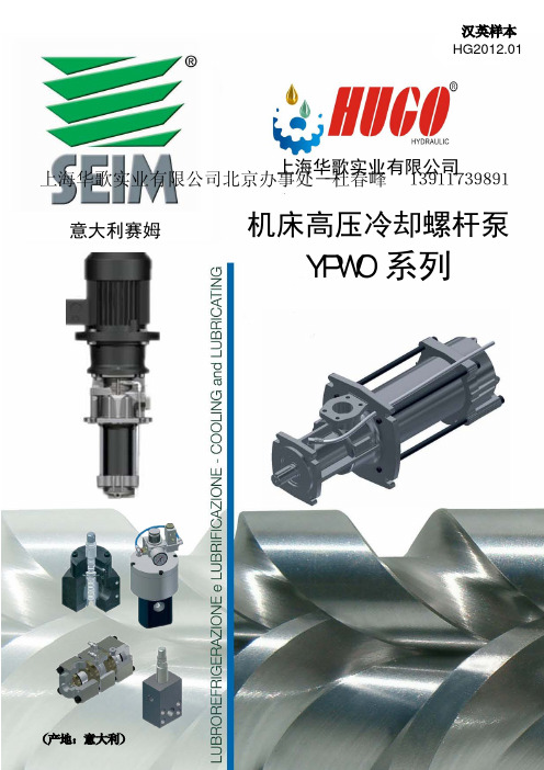
意大利SEIM机床高压冷却泵
上海华歌实业有限公司 上海华歌实业有限公司北京办事处--杜春峰 13911739891
意大利赛姆
机床高压冷却螺杆泵
YPWO 系列
(产地:意大利)
公司简介
上海华歌实业有限公司是一家经营欧美流体与传动产品的 专业公司,是欧美很多著名公司中国一级经销商,公司致力于解 决液压,润滑,开关/传感器,冷却,传动,水泵等机电领域的问 题,特别擅长解决疑难问题。本公司与很多外国公司有良好的合 作关系。
SEIM可提供下列:
1、含电机的泵组(包括联轴器) 2、安全阀或控制阀(可选项) 3、含有管路和浸入式泵组的油箱盖板(可选项)
典型应用:
1、机床设备冷却和润滑* 2、深孔钻床* 3、低润滑性的介质输送 4、热交换器和能量回收系统的中心单元 5、轻质燃油的循环系统 6、油箱填充和油/燃料的输送 *5%油含量(最小) 7、泵体使用了铸铁结构可以应用于动力和高压润滑 行业(如造船和电力)
success for the YPO6 Series in our minds-by which receive the the succesfull characteristics by integrat-
mented hydraulic efficiency which provides outstanding performances. In this catalogue you will be guided to the selection of
使用参数 / OPERATING DATA 介质- Handled fluid
粘度范围 - Viscosity range 泵转速- Pump speed
转向(从轴端看)- Rotation (viewed from coupling end) 过滤精度- Recommendedfiltration
EL Matic TM EL Matic TM 安全指南说明书

•
除非已正确安装所有保压部件,否则不要对只完成部分组装的执行
机构施加压力。
•
请咨询您的过程或安全工程师,以了解为保护过程介质而必须采取
的其他任何措施。
•
取下端盖后,不要使用气压从执行机构机体上取下活塞。
! 注意
对执行机构加压后,请勿将行程限位器彻底关闭。当调节行程限位器而且执 行机构仍处于加压状态时,将行程限位器彻底关闭可能会导致它“迸射”。
EL-O-Matic F 系列
气动齿轮齿条执行机构
安全指南 DOC.SG.EF.ZH 修订版 5
2022 年 5 月
EL MaticTM
笔记 2022 年 5 月
此页有意留为空白
安全指南 DOC.SG.EF.ZH 修订版 5
安全指南 DOC.SG.EF.ZH 修订版 5
目录 2022 年 5 月
2
常规信息
安全指南 DOC.SG.EF.ZH 修订版 5
第2节: 常规信息
2022 年 5 月
2.3
部件订购
为以前的产品订购部件时,请务必指明产品的类型、尺寸和序列号并提供您 掌握的所有其他相关信息,例如部件材料、产品已投入使用的时间以及常规 工作条件。如果在最初购买之后对本产品进行了重新配置,请在订购部件时 附上这些信息。
第2节 : 常规信息
2.1 2.2
一般应用
EL-O-Matic F 齿轮齿条式执行机构用于实现蝶阀、球阀、和旋塞阀等角行程 阀门的自动化和操作。 齿轮齿条式执行机构还可以用于操作排气百叶窗和其他角行程应用场合。 本产品适用于特定的工作条件范围:压力、环境温度、工作介质以及可能 适用的其他规格。请勿将本产品暴露在超过其既定范围的工作条件或多变 环境中。 如果不确定这些条件或多变环境是否合适,请联系您的艾默生过程管理销售 办事处以寻求协助。请提供产品的类型、尺寸、序列号以及您掌握的所有其 他相关信息。
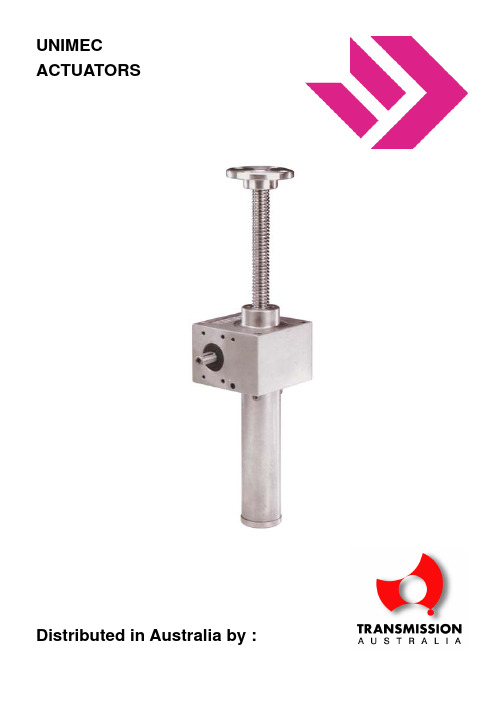
Unimec_Screwjack
UNIMECACTUATORSDistributed in Australia by :DESCRIPTIONEase of use, high dependability, and low maintenance all make worm gear screw jacks ideal for a wide variety of uses. They can be used to lift, pull, move, or align any load, even if highly unbalanced, with perfect synchronisation offered by no other movement method. UNIMEC mechanical jacks are absolutely IRREVERSIBLE, that is, they can support their loads with no need to employ brakes or other locking systems. The jacks can be deployed individually or in groups properly connected with shafts, joints, and/or bevel gear boxes. They can be driven by electrical motors, with either alternating or direct current, as well as hydraulic or pneumatic motors. They can be driven manually or with any other type of transmission. In addition to the models shown on the following pages, UNIMEC can produce jacks custom designed to meet the requirements of particular machines.UNIMEC mechanical screw jacks are designed and built using innovative technology in order to satisfy the most demanding and sophisticated applications. The units are built with special care, and the outer surfaces completely finish machined, making mounting easier and facilitating the use of supports, flanges, rocking pins, or whatever else a project may require. DOUBLE GUIDES throughout the product line assure optimum performance even under the most strenuous operating conditions. Special sealing systems enable the WORM SCREW/WORM WHEEL group to operate in a bath of long-lasting lubricant.MODELSTP: a threaded spindle with axial movement. Rotation of the drive shaft turns the worm wheel and generates straight-line axial movement of the threaded spindle. THE THREADED SPINDLE MUST HAVE A ROTATIONAL LIMIT.TPR: with threaded spindle and support nut. Rotation of the drive shaft turns the worm wheel, which is attached to the threaded spindle, thus turning the spindle as well. The external support nut (lead nut), fastened to the load, is what actually moves. THE SUPPORT NUT MUST HAVE A ROTATIONAL LIMIT.END FITTINGSTo meet the widest possible range of needs, various types of end fittings are available, and can be custom made upon request.CASINGSCasings are made of various materials depending on the size of the jack. Those in the 183 series are made of cast aluminum, those between the 204 and 9010 series are made of high grade cast iron; and in the heavy duty series, models from 10012 to 16016, the casing is made of carbon steel.WORM SCREWSFor the entire line of jacks, the worm screws are made of a special case-hardened steel, UNI 7846 18 Ni-Cr-Mo 5, and are tempered and thoroughly ground on both the threads and shaft.WORM WHEEL AND SUPPORT NUTThe worm wheels and support nuts (lead nuts) are made of a special high-resistance UNI 5273 copperalloy bronze. The Acme threading meets the DIN 103 norms. The teeth on the worm wheels are designed especially for our jacks and can easily support heavy-duty use.THREADED SPINDLESThe threaded spindles throughout the product line are made of hardened and tempered UNI 7845-C 40 carbon steel with Acme threading which complies with DIN 103 norms. Threaded spindles made of AISI stainless steel or other materials are available upon request.PROTECTIONProtection can be added in order to keep dust and foreign matter from coming into contact with the threaded spindle and causing damage. For the TP series, the exposed lower part of the spindle is covered by a steel sleeve and the upper part by elastic bellows made of nylon and PVC. The TPR series is protected by this type of elastic bellows on both the top and bottom.BEARINGSTop-quality taper ball-bearings are used on all sizes. ORDERING DATAORDERING DATATYPE (TP/TPR) TPSIZE 306RATIO 1/5TRAVEL [mm] 1000END KITTING TFPROTECTION PR-PEMODEL BMOTOR FLANGE MEC80B5MODEL OPTION SU-POPRODUCT LINE MODELSTYPE: TPDescription: THREADED SPINDLE WITH AXIALMOVEMENTRotation of the drive shaft turns the worm wheel andgenerates straight-line axial movement of the threadedshaft. THE THREADED SPINDLE MUST HAVE AROTATIONAL LIMIT.Type: TPRDescription: THREADED SPINDLE WITH SUPPORTNUTRotation of the drive shaft turns the worm wheel, which isattached to the threaded spindle, thus turning the spindleas well. The external support nut (lead nut), fastened tothe load, is what actually moves. THE SUPPORT NUTMUST HAVE AROTATIONAL LIMITOPTIONSM"TP" model screw jacksequipped for direct attachmentto a motor: Single phase, three-phase, selfbraking, direct current,hydraulic, pneumatic.M"TPR" model screw jacksequipped for direct attachmentto a motor: Single phase, three-phase, selfbraking, direct current,hydraulic, pneumatic.C"TP" model screw jacksequipped for direct attachmentto a motor by a housing andjoint: Single phase, three-phase,self-braking, direct current,hydraulic, pneumatic.C"TPR" model screw jacksequipped for direct attachment to a motor by a housing and joint : single phase, three-phase, self-braking, direct current,hydraulic, pneumatic. R"TP" model jacks equipped for direct attachment to a reducer or motorized reducer:Worm screw, coaxial, etc. R"TPR" model jacks equipped for direct attachment to a reducer or motorized reducer: Wormscrew, coaxial, etc."TP" MODEL JACKSvarious end fittings PR“TP” MODEL JACKSWITH RIGID PROTECTION PRO“TP” model jacks with rigid protection in an oil bathPE“TP” model jacks with elastic protection PE“TPR” model jacks with elastic protection PRF“TP” model jacks with rigid protection and rotation limitsPRA“TP” model jacks with rigidprotection, dual-guide anti-rotation AR“TP” model jacks withchanneled anti-rotation spindle CS“TP” model jacks with safety nutCSU“TP” model jacks with monitored safety nut CS“TPR” model jacks with safety nut CSU“TPR” model jacks with monitored safety nutSU“TP” model jacks with wear indicator SU“TPR” model jacks with wear indicator SUA“TP” MODEL JACKS WITH AUTOMATIC WEAR INDICATORSUA“TPR” model jacks with automatic wear indicator RG“TP” model jacks with backlash restriction RG“TPR” MODEL JACKS WITH BACKLASH RESTRICTIONCR“TP” model jacks with rotation monitoring CR“TPR” model jacks with rotation monitoring CT“TP” MODEL JACKS WITH CASE TEMPERATURE CONTROLCTC“TPR” model jacks with case temperature control SP“TP” model jacks withsupplemental mounting plate SP“TPR” model jacks with supplemental mounting platePO“TP” model jacks with eyelet rotation terminals P“TP” model jacks with rocking brackets P“TPR” model jacks with rocking bracketsAG“TP” model jacks with supplemental guides FP“TP” model jacks with holes through the case FP“TPR” model jacks with holes through the caseDA“TP” model jacks double action version DA“TPR” model jacks double action version DAR“TPR” model jacks staggered double action versionAM“TP” model jacks with reinforced spindleAM“TPR” model jacks withreinforced spindleThreaded spindles and support nuts Acme threadingAssembly schemesDirection of rotation and movement of spindles and support nutsProximity and supportSPECIFICATION LOAD ANALYSIS AND COMPOSITIONChoosing the right jack, and hence also its proper functioning, depends critically on identifying the real load acting on the jack. The real load is made-up ofdifferent types of loads: COMPRESSION, TRACTION AND RADIAL LOADS.The loads can be defined as follows: – STATIC loads– DYNAMIC loadsThey can be:– Loads in TENSION– Loads in COMPRESSION– RADIAL loads– Loads from single or bi-directional SHOCKS– COMBINATION loadsVIBRATIONSUNIMEC mechanical jacks with acme threaded spindles are absolutely IRREVERSIBLE by design and need no braking systems to maintain their position. We recommend contacting our Technical Office whenever jacks are installed in applications where there are strong vibrations.STATIC LOADS TRACTIONThe maximum loads for all models and sizes are shown in the specification tables.Shocks and/or radial loads reducethese maximum values.COMPRESSIONThe maximum load is determined by the length of the threaded spindle. As a function of the limit of the jack and the Eulero/Tetmajerformulas.compressionradialtractionradialtractioncompressionradialradialRADIALThese loads in particular producelateral movement of the threaded spindle, and induces bending whichis damaging and limits the capacity ofthe jack. Graphs show the maximumload values as a function of spindle length. Our Technical Office isalways available for furtherverification.TILTTilting loads in static applicationshave the same effect as radial loadsand thus the same considerationsapply.DYNAMIC LOADSTRACTIONThe maximum applicable tension is determined by several factors: thermal capacity, ambient temperature, service level, and any radial loads or shocks.Power tables must be consulted.COMPRESSIONThe maximum compression load is determined by several factors: The length of the threaded spindle, ambient temperature, service level, and any radial loads or shocks. It's important verify power tables. Furthermore, a load which causes the threaded spindle to bend requires additional examination. As a function of the limit of the jack and theEuler/Tetmajer formulas, the maximum load can be determined.RADIALRadial loads ARE NOT ALLOWED in dynamic applications. Whenever a project absolutely must use jacks with radial loads, our Technical Office must be contacted. TILTWhenever the load being moved is radial and not perpendicular to the jack, an appropriate guiding mechanism must be used in order to not produce radial loads or tilt. The following formula gives the minimum length of the guide S in relation to the length L and thefriction of the guide µ.It is apparent that coarse play between the guide and the column could cause significant and detrimental lateral loads on the jack’s threaded spindle.LOADS ON THE DRIVE SHAFTS (Worm Screw)MAXIMUM RADIAL LOAD –For proper operation of the screw jack, check that the radial loads from the drive source do not exceed thevalues shown in the table.Size 183 204 306 407 559 7010 8010 9010 1001212014 14014 16016 Fr (daN) 10 22 45 60 60 90 90 100 250 250 300 300TORQUE MOMENTWhen mounting more than one jack in series, do not exceed the values in the following table.Size 183 204 306 407 559 7010 8010 9010 10012 12014 1401416016 fast ratio 2.3 5.43 6.9 49.06 49.06 84.78 84.78 - - - - - normal ratio 2.3 5.43 15.43 12.86 12.86 84.78 84.78 202 522 522 823 823 slow ratio - 4.18 18.31 15.43 15.43 49.06 49.06 202 441441984984LOADS ASSOCIATED WITH HORIZONTAL MOUNTINGThe weight of the spindle itselfcauses it to bend and acts as a radial load. The degree of flexing, and thus the size of the radial load, is afunction of the type of screw jack, the length of its spindle, its limits, and the way it is mounted.RADIAL BACKLASHUNIMEC jacks are made with DOUBLE GUIDES in order keep the radial backlash of the threaded shaft to aminimum. A slight backlash can nonetheless be detected at the end of the spindle, and its magnitude depends on the sizes of the jack and the threaded spindle.PRECISION OF THE THREADED AXIS PITCHSpecial manufacturing processes allow the threaded axes to be made with great precision, enough to keep the maximum pitch error to within 0.05 to 0.08 mm over a length of 300 mm. AXIAL BACKLASHAxial backlash in the threaded spindle is caused by a natural and necessary operating tolerance between the threaded spindle and the worm wheel for TP models, and between the threaded spindle and the support nut (lead nut) for the TPR models. This backslash can be limited using a PLAY RETENTION nut.ALLOWABLE RADIAL LOADAs stated above, RADIAL LOADS are damaging and the main cause of breakdowns. Besides being caused by misalignments between the threaded axis and the load, lateral loads can be caused by imprecise mounting that place the threaded spindle in an abnormal position. This results in poor contact between the screw shaft and support nut on TPR models, and between the screw shaft and worm wheel on TP models. DOUBLE GUIDES on TP models allow abnormal positions of the threaded spindle to be partially corrected before coming into contact with the worm wheel. In TPR models, it is the external support nut which comes into contact with the threaded spindle, hence making it impossible to make corrections except through the use of special mountings as explained in detail in the section on mounting the support nut. Next graphs show the allowable radial loads as a function of the length of the threaded spindle for STATIC applications. Our Technical Office must be contacted for dynamic applications.MAXIMUM RADIAL LOAD ALLOWED IN STATIC APPLICATIONSmaximum radial load [daN]maximum radial load [daN]MOUNTING THE SUPPORT NUT Drawing A. The support nut is fastened to the load with special screws which allow the support nut to adapt to the position of the threaded spindle.Drawing B. The support nut is fastened to the load with brackets which prevent rotation but still allowing the support nut to adapt to the position of the threaded spindle.Drawing C. The support nut is fastened to the load with brackets which prevent rotation. An upper guide ring provides additional support.Drawing D. Double guide rings deliver greater dependability than system C.APPLICATIONSTRAVEL –The maximum values for the travel are determined by the lengths of the commercial steel rods (normally 4 to 6 meters). Spindles with longer travels are available upon request. SPEED –The allowable linear velocity of a jack is determined by several factors:- JACK TYPE and transmission RATIO- THERMAL CAPACITY- DYNAMIC LOAD- ENVIRONMENTAL TEMPERATURE- SERVICEThe power tables show the power and pair necessary – and the maximum speed – as a function of the load. AMBIENT TEMPERATUREAll values shown in this catalogue are for an ambient temperature of 20 °C. For operation in different temperatures, the corrective factor “t” must be calculated. To determine the actual load capacity of the jack, the capacity of the jack must be multiplied by the corrective factor “t”.tSERVICE LOADThe power tables refer to 30% service over 10 minutes, or 20% service over 60 minutes, and anenvironmental temperature of 20 °C. To determine the correct load for different service loads, the dynamic load must be multiplied by the ED coefficient given in the diagram below. ED% service over 10 minutes ED% service over 60 minutesMANUAL OPERATIONAll jacks in the series can be operated manually. The following table gives the maximum load that can be moved for different jack ratios, given a force of 5 daN on a handwheel with a radius of 250 mm.Greater loads can be moved by applying furtherreductions to the jack or by increasing the radius of the handwheel.Size 183 204 306 407 559 7010 8010 9010 10012 12014 14014 16016 fast ratio 500 1000 2000 1500 1000 900 860 - - - - - normal ratio 500 1000 2500 2900 2000 1600 1500 1200 1100 1000 1000 900 slow ratio - 1000 2500 5000 4300 3200 3200 2400 2300 1800 2000 1600MOTORIZED OPERATIONMotors can be used for all jacks in the series. The power tables give the motor power and the input torque moment as a function of the ratio, dynamic load, and linear velocity, under service loads of 30% over 10 minutes up to 20% over 60minutes.EMERGENCY OPERATIONIn the absence of electrical power, individual jacks or complete installations of jacks can be operated manually using a crank placed over the free end of the jack’s shaft. When self-braking motors or wormscrew reducers are used, the brake must be released or the reducer made reversible. Important: It is advisable to equip the emergency operation mechanism with a device to cut the electric circuit. EFFICIENCYThe efficiency of the jacks is given in the descriptive tables. When more than one jack is mounted together, the calculation for the overall efficiency must take into account the efficiencies of the coupling devices. Normally, the following values apply:– Two jacks 95%– Three jacks 90%– Each additional jack decreases the value an additional 5%.HEATSince a mechanical screw jack is an irreversible device, it has relatively low heat output. The energy output will not heat the jack to over 80 °C under proper operating conditions.DESCRIPTIVE TABLESSize 183 204 306 407 559 7010 8010 901010012 12014 14014 16016 Maximum load [daN] 500 1000 2500 5000 10000 20000 25000 35000 40000 60000 80000 100000 Acme threadingDiameter x pitch18x3 20x4 30x6 40x7 55x9 70x10 80x10 100x12 100x12 120x14 140x14 160x16 Screw travel for eachturn of the lead nut[mm]3 4 6 7 9 10 10 12 12 14 14 16fast 1/5 1/5 1/5 1/5 1/5 1/51/5 - - - - - normal 1/20 1/10 1/10 1/10 1/10 1/10 1/10 1/10 1/10 1/10 1/12 1/12 Theoreticalratioslow - 1/30 1/30 1/30 1/30 1/30 1/30 1/30 1/30 1/30 1/36 1/36fast 4/20 4/19 4/19 6/30 6/30 5/265/26 - - - - - normal 1/20 2/21 3/29 3/30 3/30 3/29 3/29 3/30 3/31 3/31 3/36 3/36 Real ratioslow - 1/30 1/30 1/30 1/30 1/30 1/30 1/30 1/30 1/30 1/36 1/36fast 0.6 0.8 1.2 1.4 1.8 2.02.0 - - - - -normal 0.15 0.4 0.6 0.7 0.9 1.0 1.0 1.2 1.2 1.4 1.16 1.33 Travel of thethreadedspindle foreach turn ofthe wormscrew [mm]slow - 0.13 0.2 0.23 0.3 0.33 0.33 0.4 0.4 0.47 0.38 0.44fast 29 31 30 28 25 23 22 - - - - -normal 24 28 26 25 22 21 20 18 18 17 16 15 Efficiency %slow - 20 18 18 17 14 14 12 12 11 10 9 Operating temperature -10 / 80 °C (For conditions outside this range, contact our Techincal Office) Lubrification FINA CERAN AD or equivalentAcme screw weight per100 mm [kg]0.16 0.22 0.5 0.9 1.8 2.8 3.7 5.6 5.6 8.1 11 14 Weight of jack (withoutscrew) [kg]1.8 5.9 6.5 18 34 56 62 110 180 180 380 380 COLUMN LOADThe following graphics show the maximum load, calcualted with Eulero-Tetmajer formulas with a safety coefficient of 4, avaiablefor different jack size under three different constraints.EULERO 1spindle lenght [mm] spindle lenght [mm]EULERO 2spindle lenght [mm]spindle lenght [mm]EULERO 3spindle lenght [mm]spindle lenght [mm]POWERThe nominal power PN required by the jack is given by theformula below:P = Power requirement [kW]C = Total load to be moved (inclused correction dued to service factor)[daN]V = Linear speed of the load [m/min]η1 = Efficiency of the jackThe corrected nominal power PNC is the actual power to apply to a jack or a group of jacks and is given by the formula below which includes the following coefficients:η2 = Efficiency of the configuration (based on the number of jacks connected)η3 = Efficiency of the transmission devices (belts, chains, bevel gear boxes, reducers, etc.)η4 = Efficiency of the structure (caused by the resistance of guides, sliding parts, etc.)So the formula for the corrected nominal power PNC is given by:TORQUE MOMENT DETERMINATIONThe above information for determining the power also applies to determining the nominal torque MtN and the corrected torque MtC given by the formulas below.Mt = Input torque moment [daNm]C = Total load to be moved (inclused correction dued to service factor)[daN]V = Linear speed of the load [m/min]n = Input rpm [rpm]η1 − η2 − η3 − η4 = Efficiency factors (see “Power calculation”)Check that the values given by the formulae, in light of the number of jacks deployed, are less than or equal to the values given in the following tables. In order for the jack to function properly it is CRITICAL to remember that if the values obtained fall in the shaded area the jack cannot be used. In such a case, check into the possibility of using a larger jack.POWER TABLESSIZE 183Load [daN] 50040030020010050Ratio Round in[rpm]Screwtravel[mm/min]Pn[kW]Mt[daNm]Pn[kW]Mt[daNm]Pn[kW]Mt[daNm]Pn[kW]Mt[daNm]Pn[kW]Mt[daNm]Pn[kW]Mt[daNm] 1500 900 0.25 0.17 0.21 0.14 0.15 0.1 0.1 0.07 0.07 0.03 0.07 0.03 1000 600 0.17 0.17 0.14 0.14 0.1 0.1 0.07 0.07 0.07 0.03 0.07 0.03 750 450 0.13 0.17 0.1 0.14 0.08 0.1 0.07 0.07 0.07 0.03 0.07 0.03 500 300 0.09 0.17 0.07 0.14 0.07 0.1 0.07 0.07 0.07 0.03 0.07 0.03 300 180 0.07 0.17 0.07 0.14 0.07 0.1 0.07 0.07 0.07 0.03 0.07 0.03 100 60 0.07 0.17 0.07 0.14 0.07 0.1 0.07 0.07 0.07 0.03 0.07 0.031/550 30 0.07 0.17 0.07 0.14 0.07 0.1 0.07 0.07 0.07 0.03 0.07 0.03Load [daN] 50040030020010050Ratio Round in[rpm]Screwtravel[mm/min]Pn[kW]Mt[daNm]Pn[kW]Mt[daNm]Pn[kW]Mt[daNm]Pn[kW]Mt[daNm]Pn[kW]Mt[daNm]Pn[kW]Mt[daNm] 1500 225 0.08 0.06 0.07 0.05 0.07 0.04 0.07 0.04 0.07 0.04 0.07 0.04 1000 150 0.07 0.06 0.07 0.05 0.07 0.04 0.07 0.04 0.07 0.04 0.07 0.04 750 112.5 0.07 0.06 0.07 0.05 0.07 0.04 0.07 0.04 0.07 0.04 0.07 0.04 500 75 0.07 0.06 0.07 0.05 0.07 0.04 0.07 0.04 0.07 0.04 0.07 0.04 300 45 0.07 0.06 0.07 0.05 0.07 0.04 0.07 0.04 0.07 0.04 0.07 0.04 100 15 0.07 0.06 0.07 0.05 0.07 0.04 0.07 0.04 0.07 0.04 0.07 0.041/2050 7.5 0.07 0.06 0.07 0.05 0.07 0.04 0.07 0.04 0.07 0.04 0.07 0.04Load [daN] 1000800600400300200100Ratio Round in[rpm]Screwtravel[mm/min]Pn[kW]Mt[daNm]Pn[kW]Mt[daNm]Pn[kW]Mt[daNm]Pn[kW]Mt[daNm]Pn[kW]Mt[daNm]Pn[kW]Mt[daNm]Pn[kW]Mt[daNm] 1500 1200 0.64 0.42 0.51 0.33 0.38 0.25 0.26 0.17 0.19 0.13 0.13 0.09 0.07 0.05 1000 800 0.43 0.42 0.34 0.33 0.26 0.25 0.17 0.17 0.13 0.13 0.09 0.09 0.07 0.05 750 600 0.32 0.42 0.26 0.33 0.19 0.25 0.13 0.17 0.1 0.13 0.07 0.09 0.07 0.05 500 400 0.21 0.42 0.17 0.33 0.13 0.25 0.09 0.17 0.07 0.13 0.07 0.09 0.07 0.05 300 240 0.13 0.42 0.11 0.33 0.11 0.25 0.07 0.17 0.07 0.13 0.07 0.09 0.07 0.05 100 80 0.07 0.42 0.07 0.33 0.07 0.25 0.07 0.17 0.07 0.13 0.07 0.09 0.07 0.051/550 40 0.07 0.42 0.07 0.33 0.07 0.25 0.07 0.17 0.07 0.13 0.07 0.09 0.07 0.05Load [daN] 1000800600400300200100Ratio Round in[rpm]Screwtravel[mm/min]Pn[kW]Mt[daNm]Pn[kW]Mt[daNm]Pn[kW]Mt[daNm]Pn[kW]Mt[daNm]Pn[kW]Mt[daNm]Pn[kW]Mt[daNm]Pn[kW]Mt[daNm] 1500 600 0.36 0.23 0.3 0.19 0.22 0.14 0.14 0.09 0.11 0.07 0.08 0.05 0.07 0.03 1000 400 0.24 0.23 0.2 0.19 0.14 0.14 0.09 0.09 0.07 0.07 0.07 0.05 0.07 0.03 750 300 0.18 0.23 0.15 0.19 0.11 0.14 0.07 0.09 0.07 0.07 0.07 0.05 0.07 0.03 500 200 0.12 0.23 0.1 0.19 0.07 0.14 0.07 0.09 0.07 0.07 0.07 0.05 0.07 0.03 300 120 0.07 0.23 0.07 0.19 0.07 0.14 0.07 0.09 0.07 0.07 0.07 0.05 0.07 0.03 100 40 0.07 0.23 0.07 0.19 0.07 0.14 0.07 0.09 0.07 0.07 0.07 0.05 0.07 0.031/1050 20 0.07 0.23 0.07 0.19 0.07 0.14 0.07 0.09 0.07 0.07 0.07 0.05 0.07 0.03Load [daN] 1000800600400300200100Ratio Round in[rpm]Screwtravel[mm/min]Pn[kW]Mt[daNm]Pn[kW]Mt[daNm]Pn[kW]Mt[daNm]Pn[kW]Mt[daNm]Pn[kW]Mt[daNm]Pn[kW]Mt[daNm]Pn[kW]Mt[daNm] 1500 200 0.17 0.11 0.13 0.08 0.11 0.07 0.07 0.05 0.07 0.03 0.07 0.03 0.07 0.03 1000 133 0.12 0.11 0.08 0.08 0.07 0.07 0.07 0.05 0.07 0.03 0.07 0.03 0.07 0.03 750 100 0.08 0.11 0.07 0.08 0.07 0.07 0.07 0.05 0.07 0.03 0.07 0.03 0.07 0.03 500 67 0.07 0.11 0.07 0.08 0.07 0.07 0.07 0.05 0.07 0.03 0.07 0.03 0.07 0.03 300 40 0.07 0.11 0.07 0.08 0.07 0.07 0.07 0.05 0.07 0.03 0.07 0.03 0.07 0.03 100 13 0.07 0.11 0.07 0.08 0.07 0.07 0.07 0.05 0.07 0.03 0.07 0.03 0.07 0.031/3050 6.7 0.07 0.11 0.07 0.08 0.07 0.07 0.07 0.05 0.07 0.03 0.07 0.03 0.07 0.03Load [daN] 2500200015001000750500250Ratio Round in[rpm]Screwtravel[mm/min]Pn[kW]Mt[daNm]Pn[kW]Mt[daNm]Pn[kW]Mt[daNm]Pn[kW]Mt[daNm]Pn[kW]Mt[daNm]Pn[kW]Mt[daNm]Pn[kW]Mt[daNm] 1500 1800 2.45 1.6 1.96 1.28 1.47 0.69 0.98 0.64 0.74 0.48 0.49 0.32 0.25 0.17 1000 1200 1.64 1.6 1.31 1.28 0.98 0.69 0.65 0.64 0.49 0.48 0.33 0.32 0.17 0.17 750 900 1.23 1.6 0.98 1.28 0.74 0.69 0.49 0.64 0.37 0.48 0.25 0.32 0.13 0.17 500 600 0.82 1.6 0.66 1.28 0.49 0.69 0.33 0.64 0.25 0.48 0.17 0.32 0.1 0.17 300 360 0.49 1.6 0.4 1.28 0.3 0.69 0.2 0.64 0.15 0.48 0.1 0.32 0.1 0.17 100 120 0.17 1.6 0.13 1.28 0.1 0.69 0.1 0.64 0.1 0.48 0.1 0.32 0.1 0.171/550 60 0.1 1.6 0.1 1.28 0.1 0.69 0.1 0.64 0.1 0.48 0.1 0.32 0.1 0.17Load [daN] 2500200015001000750500250Ratio Round in[rpm]Screwtravel[mm/min]Pn[kW]Mt[daNm]Pn[kW]Mt[daNm]Pn[kW]Mt[daNm]Pn[kW]Mt[daNm]Pn[kW]Mt[daNm]Pn[kW]Mt[daNm]Pn[kW]Mt[daNm] 1500 900 1.43 0.93 1.14 0.74 0.86 0.56 0.57 0.37 0.43 0.28 0.29 0.19 0.16 0.1 1000 600 0.96 0.93 0.76 0.74 0.58 0.56 0.38 0.37 0.29 0.28 0.2 0.19 0.1 0.1 750 450 0.72 0.93 0.57 0.74 0.43 0.56 0.29 0.37 0.22 0.28 0.15 0.19 0.1 0.1 500 300 0.48 0.93 0.38 0.74 0.28 0.56 0.19 0.37 0.15 0.28 0.1 0.19 0.1 0.1 300 180 0.28 0.93 0.23 0.74 0.18 0.56 0.12 0.37 0.1 0.28 0.1 0.19 0.1 0.1 100 60 0.1 0.93 0.1 0.74 0.1 0.56 0.1 0.37 0.1 0.28 0.1 0.19 0.1 0.11/1050 30 0.1 0.93 0.1 0.74 0.1 0.56 0.1 0.37 0.1 0.28 0.1 0.19 0.1 0.1Load [daN] 2500200015001000750500250Ratio Round in[rpm]Screwtravel[mm/min]Pn[kW]Mt[daNm]Pn[kW]Mt[daNm]Pn[kW]Mt[daNm]Pn[kW]Mt[daNm]Pn[kW]Mt[daNm]Pn[kW]Mt[daNm]Pn[kW]Mt[daNm] 1500 300 0.68 0.44 0.56 0.36 0.42 0.27 0.28 0.18 0.22 0.14 0.14 0.09 0.07 0.045 1000 200 0.45 0.44 0.37 0.36 0.28 0.27 0.19 0.18 0.14 0.14 0.1 0.09 0.07 0.045 750 150 0.34 0.44 0.28 0.36 0.21 0.27 0.14 0.18 0.11 0.14 0.07 0.09 0.07 0.045 500 100 0.23 0.44 0.19 0.36 0.14 0.27 0.1 0.18 0.07 0.14 0.07 0.09 0.07 0.045 300 60 0.14 0.44 0.11 0.36 0.08 0.27 0.07 0.18 0.07 0.14 0.07 0.09 0.07 0.045 100 20 0.07 0.44 0.11 0.36 0.08 0.27 0.07 0.18 0.07 0.14 0.07 0.09 0.07 0.0451/3050 10 0.07 0.44 0.11 0.36 0.08 0.27 0.07 0.18 0.07 0.14 0.07 0.09 0.07 0.045Load [daN] 500040003000200015001000500Ratio Round in[rpm]Screwtravel[mm/min]Pn[kW]Mt[daNm]Pn[kW]Mt[daNm]Pn[kW]Mt[daNm]Pn[kW]Mt[daNm]Pn[kW]Mt[daNm]Pn[kW]Mt[daNm]Pn[kW]Mt[daNm] 1500 2100 6.13 3.98 4.9 3.18 3.68 2.39 2.45 1.59 1.84 1.2 1.23 0.8 0.62 0.4 1000 1400 4.09 3.98 3.27 3.18 2.15 2.39 1.64 1.59 1.23 1.2 0.82 0.8 0.41 0.4 750 1050 3.06 3.98 2.45 3.18 1.8 2.39 1.23 1.59 0.92 1.2 0.62 0.8 0.31 0.4 500 700 2.04 3.98 1.64 3.18 1.23 2.39 0.82 1.59 0.62 1.2 0.41 0.8 0.21 0.4 300 420 1.23 3.98 0.98 3.18 0.74 2.39 0.49 1.59 0.37 1.2 0.25 0.8 0.13 0.4 100 140 0.41 3.98 0.33 3.18 0.25 2.39 0.17 1.59 0.13 1.2 0.1 0.8 0.1 0.41/550 70 0.21 3.98 0.17 3.18 0.13 2.39 0.1 1.59 0.1 1.2 0.1 0.8 0.1 0.4Load [daN] 500040003000200015001000500Ratio Round in[rpm]Screwtravel[mm/min]Pn[kW]Mt[daNm]Pn[kW]Mt[daNm]Pn[kW]Mt[daNm]Pn[kW]Mt[daNm]Pn[kW]Mt[daNm]Pn[kW]Mt[daNm]Pn[kW]Mt[daNm] 1500 1050 3.6 2.3 2.8 1.8 2.1 1.34 1.4 0.9 1.05 0.67 0.7 0.45 0.35 0.23 1000 700 2.4 2.3 1.85 1.8 1.38 1.34 0.92 0.9 0.69 0.67 0.46 0.45 0.23 0.23 750 525 1.77 2.3 1.4 1.8 1 1.34 0.7 0.9 0.52 0.67 0.35 0.45 0.18 0.23 500 350 1.18 2.3 0.92 1.8 0.69 1.34 0.46 0.9 0.35 0.67 0.23 0.45 0.12 0.23 300 210 0.71 2.3 0.56 1.8 0.42 1.34 0.28 0.9 0.21 0.67 0.14 0.45 0.1 0.23 100 70 0.24 2.3 0.19 1.8 0.14 1.34 0.1 0.9 0.1 0.67 0.1 0.45 0.1 0.231/1050 35 0.12 2.3 0.1 1.8 0.1 1.34 0.1 0.9 0.1 0.67 0.1 0.45 0.1 0.23Load [daN] 500040003000200015001000500Ratio Round in[rpm]Screwtravel[mm/min]Pn[kW]Mt[daNm]Pn[kW]Mt[daNm]Pn[kW]Mt[daNm]Pn[kW]Mt[daNm]Pn[kW]Mt[daNm]Pn[kW]Mt[daNm]Pn[kW]Mt[daNm] 1500 350 1,69 1,1 1,26 0,82 0,95 0,62 0,63 0,41 0,48 0,31 0,32 0,21 0,17 0,11 1000 233 1,13 1,1 0,84 0,82 0,64 0,62 0,42 0,41 0,32 0,31 0,21 0,21 0,11 0,11 750 175 0,85 1,1 0,63 0,82 0,48 0,62 0,32 0,41 0,24 0,31 0,16 0,21 0,08 0,11 500 117 0,56 1,1 0,42 0,82 0,32 0,62 0,21 0,41 0,16 0,31 0,11 0,21 0,07 0,11 300 70 0,34 1,1 0,25 0,82 0,19 0,62 0,13 0,41 0,1 0,31 0,07 0,21 0,07 0,11 100 23 0,12 1,1 0,08 0,82 0,07 0,62 0,07 0,41 0,07 0,31 0,07 0,21 0,07 0,111/3050 11,7 0,07 1,1 0,07 0,82 0,07 0,62 0,07 0,41 0,07 0,31 0,07 0,21 0,07 0,11。
生产一致性控制计划表COP试验和检查
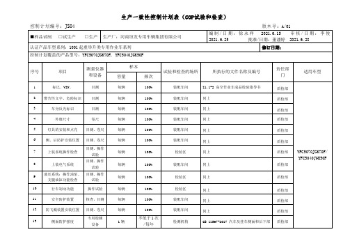
11
3C标识加施
检验区
Z4.1-2 高空作业车装配作业指导书
质检部
生产一致性控制计划表(关键生产/装配/检验过程)
控制计划编号:JS04版本号:A/01
■样品试制 □试生产 □生产
生产厂:河南垣发专用车辆集团有限公司
编制/日期:徐永祥2020.6.15审核/日期:李俊2020.6.25批准/日期:董潘婷2020.6.28
认证产品车型系列:1001起重举升类专用作业车系列
100%
检验区
同上
质检部
8
上装电气系统
目测、操作试验
每辆
100%
装配车间
同上
质检部
9
液压系统:操作油泵、支腿油缸功能检查
目测、操作试验
每辆
100%
检验区
同上
质检部
10
行车制动功能
操作试验
每辆
100%
检验区
同上
质检部
11
安全防护装置
核查,目测
每辆
100%
装配车间
同上
质检部
12
防飞溅装置安装位置
目测、卷尺
2
油泵组装
装配车间
Z4.1-2 高空作业车装配作业指导书
生产部
3
支腿组装
装配车间
同上
生产部
4
臂架组装
装配车间
同上
生产部
5
液压缸组装
装配车间
同上
生产部
6
侧后防护安装
装配车间
同上
生产部
7
灯具安装
装配车间
同上
生产部
8
反光标识粘贴
装配车间
nema标准 压缩机管口受力

《NEMA标准下的压缩机管口受力评估与应对措施》一、引言在工业生产和设备制造中,压缩机作为一种重要的能源设备,在各行业中得到了广泛的应用。
然而,压缩机的管口受力问题一直备受关注。
本文将从NEMA标准出发,对压缩机管口受力进行全面评估,并提出相应的解决措施。
二、NEMA标准的相关内容NEMA(National Electrical Manufacturers Association)是美国国家电机制造商协会,该协会制定了一系列与电气设备相关的标准。
在NEMA标准中,对于压缩机管口受力也有详细的规定。
根据NEMA标准,压缩机在设计和使用过程中,必须满足一定的受力要求,以确保其安全可靠地运行。
三、压缩机管口受力的评估1. 受力类型:压缩机在工作中会承受不同方向和大小的受力,包括拉力、压力、弯曲力等。
这些受力会直接作用于管口部位,对其造成一定程度的影响。
2. 强度评估:根据NEMA标准,对于不同材质和结构的压缩机管口,需要进行强度计算和评估,以确定其在特定工况下的受力承载能力。
3. 疲劳分析:在长期使用过程中,压缩机管口会受到交变受力的影响,从而导致疲劳破坏。
需要进行疲劳分析,评估管口的疲劳寿命和寿命期望。
四、应对措施1. 材质选择:根据NEMA标准和实际工作条件,选择合适的管口材质,包括金属、合金、塑料等。
对于不同型号和工况的压缩机,需要进行相应的材质评估和选择。
2. 结构设计:通过优化管口结构设计,提高其受力承载能力和疲劳寿命。
可以采用加强筋、减小应力集中等方式,改善管口的受力特性。
3. 强度验证:在生产和使用过程中,需要对压缩机管口的强度进行定期验证和监测,以确保其满足NEMA标准的要求。
五、个人观点和总结作为压缩机的重要组成部分,管口的受力问题不容忽视。
在实际工程中,我们应当充分理解NEMA标准的要求,对压缩机管口的受力进行全面评估,并采取相应的应对措施。
只有确保管口的安全可靠性,才能保障整个压缩机系统的正常运行。
冲床模柄孔锁紧原理

冲床模柄孔锁紧原理冲床的设计原理是将圆周运动转换为直线运动,由主电动机出力,带动飞轮,经离合器带动齿轮、曲轴(或偏心齿轮)、连杆等运转,来达成滑块的直线运动,从主电动机到连杆的运动为圆周运动。
连杆和滑块之间需有圆周运动和直线运动的转接点,其设计上大致有两种机构,一种为球型,一种为销型(圆柱型) ,经由这个机构将圆周运动转换成滑块的直线运动。
冲床对材料施以压力,使其塑性变形,而得到所要求的形状与精度,因此必须配合一组模具(分上模与下模),将材料置于其间,由机器施加压力,使其变形,加工时施加于材料之力所造成之反作用力,由冲床机械本体所吸收。
1.上模上模是整副冲模的上半部,即安装于压力机滑块上的冲模部分。
2、上模座上模座是上模最上面的板状零件,工件时紧贴压力机滑块,并通过模柄或直接与压力机滑块固定。
3、下模下模是整副冲模的下半部,即安装于压力机工作台面上的冲模部分。
4、下模座下模座是下模底面的板状零件,工作时直接固定在压力机工作台面或垫板上。
5、刃壁刃壁是冲裁凹模孔刃口的侧壁。
6、刃口斜度刃口斜度是冲裁凹模孔刃壁的每侧斜度。
7、气垫气垫是以压缩空气为原动力的弹顶器。
参阅“弹顶器”。
8、反侧压块反侧压块是从工作面的另一侧支持单向受力凸模的零件。
9、导套导套是为上、下模座相对运动提供精密导向的管状零件,多数固定在上模座内,与固定在下模座的导柱配合使用。
10、导板导板是带有与凸模精密滑配内孔的板状零件,用于保证凸模与凹模的相互对准,并起卸料(件)作用。
11、导柱导柱是为上、下模座相对运动提供精密导向的圆柱形零件,多数固定在下模座,与固定在上模座的导套配合使用。
12、导正销导正销是伸入材料孔中导正其在凹模内位置的销形零件。
13、导板模导板模是以导板作导向的冲模,模具使用时凸模不脱离导板。
14、导料板导料板是引导条(带、卷)料进入凹模的板状导向零件。
15、导柱模架导柱模架是导柱、导套相互滑动的模架。
(参阅“模架”)。
EN12209:2003机械锁

欧洲锁具标准(中文版)EN12209:2003前言---------------------------------------------------------------------------------------------------------------31. 适用范围----------------------------------------------------------------------------------------------------42. 参考标准----------------------------------------------------------------------------------------------------43. 术语,定义,符号和单位------------------------------------------------------------------------------------43.1术语和定义-----------------------------------------------------------------------------------------43.2符号,单位和缩写术语----------------------------------------------------------------------------54.分类---------------------------------------------------------------------------------------------------------83.3概述--------------------------------------------------------------------------------------------------83.4机械锁,单斜舌和锁扣板的分类----------------------------------------------------------------9 5. 要求---------------------------------------------------------------------------------------------------------135.1 概述-------------------------------------------------------------------------------------------------135.2 使用分类-------------------------------------------------------------------------------------------135.3 耐久性---------------------------------------------------------------------------------------------145.4 门重和关门力--------------------------------------------------------------------------------------155.5 适合防火/烟门使用-------------------------------------------------------------------------------155.6 安全性-----------------------------------------------------------------------------------------------155.7 防腐和使用温度-----------------------------------------------------------------------------------155.8 保安性-----------------------------------------------------------------------------------------------155.9 应用门范围-----------------------------------------------------------------------------------------205.10 钥匙操作和上锁类型----------------------------------------------------------------------------215.11 方芯操作类型-------------------------------------------------------------------------------------215.12 钥匙身份要求-------------------------------------------------------------------------------------226. 测试方法----------------------------------------------------------------------------------------------------236.1 概述--------------------------------------------------------------------------------------------------236.2 使用分类--------------------------------------------------------------------------------------------256.3 耐久性-----------------------------------------------------------------------------------------------266.4 门重和关门力--------------------------------------------------------------------------------------286.5 适合防火/烟门使用-------------------------------------------------------------------------------286.6 安全性-----------------------------------------------------------------------------------------------286.7 防腐和使用温度-----------------------------------------------------------------------------------286.8 保安性-----------------------------------------------------------------------------------------------296.9 应用门范围-----------------------------------------------------------------------------------------326.10 钥匙操作和上锁类型----------------------------------------------------------------------------326.11 方芯操作-------------------------------------------------------------------------------------------336.12 钥匙身份-------------------------------------------------------------------------------------------347. 标记----------------------------------------------------------------------------------------------------------348.合格评定--------------------------------------------------------------------------------------------------348.1最初样板测试--------------------------------------------------------------------------------------348.2生产控制--------------------------------------------------------------------------------------------358.3样品的进一步测试--------------------------------------------------------------------------------35 附录A(规范的)防火要求-------------------------------------------------------------------------------------36 附录B(规范的)测试设备附图说明-------------------------------------------------------------------------37 附录C(非规范的)取样和测试顺序-------------------------------------------------------------------------46 附录D(规范的)门应用范围----------------------------------------------------------------------------------49前言此标准(EN12209:2003)是由CEN/TC 33(“门,窗,百叶窗,建筑五金和幕墙”)技术委员会编写的,法国标准化协会掌管该委员会秘书处。
康尼车门结构原理
康尼车门结构原理康尼(Konny)是一家以汽车门为主要产品的全球知名企业。
其车门结构设计独特,具有很强的安全性和美观性。
本文将介绍康尼车门的结构原理。
车门的主要结构一辆汽车的每个车门由门板、门锁、门把手、车窗控制装置、装置卡扣等组成。
康尼车门的结构分为主要部分和辅助部分。
主要部分康尼车门中的主要部分由门板、门锁、门把手和装置卡扣构成。
门板由内板和外板组成,中间夹层一般采用高强度钢板或铝材,以确保门的安全性和强度。
门锁包括门锁钩、门锁锁舌、门锁电子控制器等,确保车门的安全性和可靠性。
门把手是汽车门的开关装置,用于打开和关闭车门。
装置卡扣是汽车门的紧固系统,顶部卡扣和锁舌卡扣相互配合,确保车门的封闭性。
辅助部分康尼车门中的辅助部分主要由刚性背板、防撞杆、防撞块、防火板、水膜器等构成。
刚性背板位于门板内侧,用于增强车门的强度和刚度。
防撞杆和防撞块可减少车辆碰撞时的损伤。
防火板用于防止火灾时火势蔓延进入车内。
水膜器负责降低风压和噪音。
康尼门锁的原理康尼门锁是一种电子控制车锁,其原理是通过电子控制器和电妙控制器的配合来完成车锁的解锁与锁定。
康尼门锁采用了防撬卡扣,能够有效地防止锁体被破坏和撬动。
当车主使用遥控器或者门把手打开车门时,电子控制器会开始工作,释放电机,使得门锁钩向上翻转,锁舌从附着在门框的紧固卡上解开,完成门的开锁操作。
当车主再次按下遥控器或者门把手关闭车门时,电子控制器给电机发送信号,使得门锁钩向下翻转,撞击上门框的紧固卡,将锁舌插入附着在门框的紧固卡里,完成门的锁定操作。
康尼车门的优势康尼车门具有很强的安全性和美观性。
它的门板加强了刚性和强度,能够有效地抵抗车辆发生碰撞时的撞击。
它的防撞杆和防撞块也能降低车辆碰撞时的冲击力。
康尼车门的防火板可以有效地防止火灾时车内车外火势的相互蔓延。
康尼门锁采用了电子控制技术,不仅可以使得应用更加方便,还可以有效地防止拉锯式破解。
康尼车门的结构原理为我们提供了了解汽车门锁设计的新视角。
