SCM-CA00B-1213-C100-CAW编码器说明书
Saia PCD1.G2100 编码器模组说明书
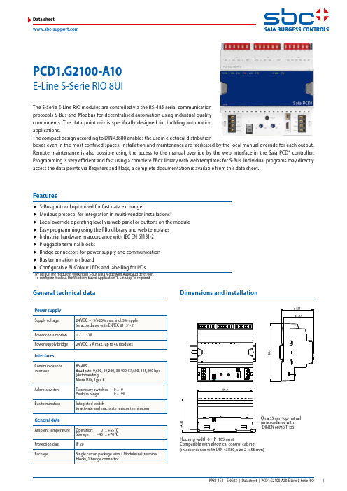
PCD1.G2100-A10E-Line S-Serie RIO 8UIData sheetThe S-Serie E-Line RIO modules are controlled via the RS-485 serial communication protocols S-Bus and Modbus for decentralised automation using industrial quality components. The data point mix is specifically designed for building automation applications.The compact design according to DIN 43880 enables the use in electrical distributionboxes even in the most confined spaces. Installation and maintenance are facilitated by the local manual override for each output. Remote maintenance is also possible using the access to the manual override by the web interface in the Saia PCD® controller. Programming is very efficient and fast using a complete FBox library with web templates for S-Bus. Individual programs may directly access the data points via Registers and Flags, a complete documentation is available from this data sheet.f S-Bus protocol optimized for fast data exchangef Modbus protocol for integration in multi-vendor installations*f Local override operating level via web panel or buttons on the module f Easy programming using the FBox library and web templates f Industrial hardware in accordance with IEC EN 61131-2 f Pluggable terminal blocksf Bridge connectors for power supply and communication f Bus termination on boardf Configurable Bi-Colour LEDs and labelling for I/Os* B y default the module is working in S-Bus Data Mode with Autobaud detection. To configure Modbus the Windows based Application “E-LineApp” is required.On a 35 mm top-hat rail ( i n accordance with DIN EN 60715 TH35)Housing width 6 HP (105 mm)Compatible with electrical control cabinet (in accordance with DIN 43880, size 2 × 55 mm)Dimensions and installationFeaturesGeneral technical dataPower supply/DA+DB-GND+24VOpenClose For easy installation the power supply and communicationbus is available together at one connector. The push-in springterminals enable wiring as well support the connector bridge.Push-in spring terminals enable wiring with rigid or flexible wireswith a diameter up to 1.5 mm². A max. of 1 mm² is permitted withcable end sleeves.Terminal technologyConnection conceptOFF No PowerGreen Communication OKGreen blink Auto bauding in progressOrange No communicationRedE rrorRed/Green alternate B ooter mode(e.g. during Firmware download)Red blink Internal fatal errorStatus LEDThe module provides an active bus termination. It is switchedoff by factory default. To enable the termination, the switchneed to be in the “Close” position.Bus terminationThe USB interface provides access to the communicationprotocol configuration. Firmware updates can also be downloaded via Saia PG5® Firmware Download tool.Service interfaceReset buttonPushed over 20 seconds: The button needs to be pushed forminimum 20 seconds and released during the first minute afterpower up. All user settings are reset to factory default values.Pushed at power up: Power off the device and press thebutton. Power on and release the button before 5 seconds havepassed. The device stays in boot mode for further actions likefirmware download etc.Input/Output configurationUniversal InputsAnalogue input mode[2] R ange 0 … 300 kΩ must be used. The temperature for NTC are not standardised and may differ depending on the manufacturer.A CSV file can be used for the value generation with a linearisation FBox. The CSV file can be found on the support page (link, see last page).Digital input modeGND +24V/DA+DB–GND +24V/DA+DB–Assignment overviewPower supply and bus terminationConnection diagrams0 … 10 V0 … 300 kOhmUniversal inputsOFF No Power Green Communication OK Green blink Auto bauding in progress Orange No communication Red E rror Red/Green alternate B ooter mode (e.g. during Firmwaredownload)Red blink Internal fatal errorStatus LEDLED SignalisationUniversal inputThe Manual override LED is Off in automatic mode and orange in case of manual override is active.LED colour f Off (automatic)f Orange manual mode active LED blink codef No blink (local manual override)f Blinking 1 flash per second (remote manual override)Manual modef Data exchange for I/O via optimised S-Busf Configurable save state for bus interruption or timeoutf Direct generation of the symbolsf Reading and writing of the status of the manual override statusf Direct compatibility with web macrosThe modules are addressed and programmed with Saia PG5® Fupla FBoxes. Web templates are available for theoperation and visualisation of the manual override function.Further information, including which FBoxes are supported,Getting Started, etc., can be found on our support page.Web templates are available for the operation and visualisationof the manual override function.Communication FBoxWeb templatesProgrammingBy using the local override function, commissioning can takeplace independently of the master station.In addition, the manual operation can also be controlledremotely using a touch panel. If the bus line is cut off, the FuplaE-Line libraryE-Line RIOs support the device setup by a windows application program connected via USB. The installer is available for down-load from the SBC support page: E-Line RIO IO Modules.The Baudrate can be defined as automatic detection(default) or set to a specific value. The drop down choice willbe available when the check box “Automatic” is unchecked.TN delay and TS delay shall be left at their default values of 2.Create a new device configurationOpen an existing device configurationSave the current settings as device configurationUpload configuration from the deviceDownload settings to the deviceThe serial communication protocol can be defined either asS-Bus or Modbus. By default the modules are delivered fromfactory with S-Bus.S-Bus settingsThe station number can be set by the rotary switches at thedevice in the range of 0 … 98. If the rotary switches are set toposition 99 the station number can be defined by the deviceconfiguration in a range of 0 … 253.Modbus settingsThe Baudrate is set by default to 115 k. It can be defined aschoice of the list.For best interoperability the Parity Mode and number ofStop Bits can also be set.S-Bus communication is based on Saia PCD® S-Bus Data Mode. Only the set-up of a unique S-Bus address within the communi-cation line is required to establish a communication between Saia PCD® controllers and E-Line RIO modules. The address can be set by the rotary switches at the front of the module. The baud rate will be learned from the network by factory default. In addition a Windows based application is available for manual parameter setup. Configuration parameters as well as manual override state and value are saved non-volatile. A delay of about one second between a manual state change and none volatile saving has to be taken into consideration.Device address f 0 … 98 Address is taken from the rotary switchesf 99Address is taken from the device configuration. The address is settable with the E-Line configuration software.Start-up procedure f Reboot: All outputs are cleared (Off state) f < 1 sec.Output in manual operation are set according to the state before power down.f Outputs in automatic modeIs no telegram received after reboot within the “safe state power-on timeout” the module enters into the safe state mode and sets the outputs according to their configured values.On reception of a valid command telegram the outputs are controlled by the communication. When no communication update followed within the “safe state com. timeout” the module enters into safe state and sets the outputs according to their configured values.Usage of the E-Line module specific FBoxesThe usage of the E-Line module specific FBoxes from the E-Line S-Bus Fupla library allows an easy and efficient commis-sioning of the E-Line RIO.The FBox allow to define and configure all possible function-alities of the E-Line RIO like manual override permission, us-age of safe state mode, behaviour and colour of the LED’s and so on.In the background, the FBox does use the fast ‘E-Line S-Bus’ protocol for a high speed communication between the mas-ter and the RIO.The following chapter describes the media and parameter mapping to Registers and Flags for individual programming. For efficient PCD programming the E-Line RIO FBox family and templates are suitable for most applications. Only individual pro-gramming (e.g. Instruction List) require standard S-Bus communication.Mode Configuration Register:0 : 0 … 10 V (default) Value scaled within Range Min and Range Max 3 : 0 … 2500 Ω Value scaled within Range Min and Range Max 4 : Pt1000 Value in 1/10°C (23.4 °C → 234)5 : Ni1000 Value in 1/10°C (23.4 °C → 234)6 : Ni1000LS Value in 1/10°C (23.4 °C → 234)8 : 0 … 300 kΩ Value scaled within Range Min and Range Max 9 : Digital inputValue for Input open, <5 V = 0, Input >10 V, 24 VDC = 1Register format:1 byte for each analogue input status. (e.g. b yte 0: AI0byte 1: AI1 byte 2: AI2 byte 3: AI3)Bit 0 Analogue input over-range Bit 1 Analogue input under-rangeStatus is cleared when the input returns to normal stateAnalogue inputsDirect access to the RIO medias with standard S-Bus send and receive telegrams** Time in 0.1 ms (e.g. 2 means 200 us) before sending the first character after line driver activation (only used for S-Bus slave protocol)*** The four registers contain the ASCII characters of the product type.E.g. for PCD1.A2000-A20:0605: 50434431H 0606: 2E413230H 0607: 30302D41H 0608: 32300000HDevice InformationModbus fulfils the requirements for standard communication protocols. It is based on Modbus RTU. The Windows based configu-ration software is required to enable and set up the Modbus communication parameters. The device address can be set up with the rotary switches at the front of the module. Configuration parameters as well as manual override state and value are saved non-volatile. A delay of about one second between a manual state change and non-volatile saving has to be taken into consideration. Device addressf0 … 98 Address is taken from the rotary switchesf99 Address is taken from the device configuration. The address is settable with the E-Line configuration soft-ware.Start-up proceduref Reboot: All outputs are cleared (Off state)f<1 sec. Output in manual operation are set according to the state before power down.f Outputs in automatic modeIs no telegram received after reboot within the “safe state power-on timeout” the module enters as will intothe safe state mode and sets the outputs according to their configured values.On reception of a valid command telegram the outputs are controlled by the communication. When no com-munication update followed within the “safe state com. timeout” the module enters into safe state and setsthe outputs according to their configured values.The following chapter describes the media and parameter mapping to Registers and Flags (=Coils).Supported Modbus services:f Function code 1 (read outputs)f Function code 3 (read registers)f Function code 15 (write multiple outputs)f Function code 16 (write multiple registers)The CRC has to be calculated over all telegram bytes starting with address field up to the last data byte. The CRC has to be attached to the data. Please find an example at the appendix of this document. For more details, please refer the publicly available Modbus documentation .Mode Configuration Register:0 : 0 … 10 V (default) Value scaled within Range Min and Range Max 3 : 0 … 2500 Ω Value scaled within Range Min and Range Max 4 : Pt1000 Value in 1/10°C (23.4 °C → 234)5 : Ni1000 Value in 1/10°C (23.4 °C → 234)6 : Ni1000LS Value in 1/10°C (23.4 °C → 234)8 : 0 … 300 kΩ Value scaled within Range Min and Range Max 9 : Digital inputValue for Input open, <5 V = 0, Input >10 V, 24 VDC = 1Register format:1 byte for each analogue input status. (e.g. b yte 0: AI0byte 1: AI1 byte 2: AI2 byte 3: AI3)Bit 0 Analogue input over-range Bit 1 Analogue input under-rangeStatus is cleared when the input returns to normal stateAnalogue inputsE.g. for PCD1.A2000-A20:1210…1217: 5043H | 4431H | 2E41H | 3230H | 3030H | 2D41H | 3230H | 0000HDevice InformationCRC Generation Example(Source: /docs/PI_MBUS_300.pdf, the following content of this page is copied from the referenced document. In case of any questions, please check out the original source)The function takes two arguments: unsigned char *puchMsg; A pointer to the message buffer containing binary data to be used for generating the CRC unsigned short usDataLen; The quantity of bytes in the message buffer. The function returns the CRC as a type unsigned short.CRC Generation Functionunsigned short CRC16(puchMsg, usDataLen) ;unsigned char *puchMsg ; /* message to calculate CRC upon */unsigned short usDataLen ; /* quantity of bytes in message */{unsigned char uchCRCHi = 0xFF ; /* high byte of CRC initialized */unsigned char uchCRCLo = 0xFF ; /* low byte of CRC initialized */unsigned uIndex ; /* will index into CRC lookup table */while (usDataLen--) /* pass through message buffer */{uIndex = uchCRCHi ^ *puchMsgg++; /* calculate the CRC */uchCRCHi = uchCRCLo ^ auchCRCHi[uIndex];uchCRCLo = auchCRCLo[uIndex];}return (uchCRCHi << 8 | uchCRCLo);}High-Order Byte Table/* Table of CRC values for high-order byte */static unsigned char auchCRCHi[] = {0x00, 0xC1, 0x81, 0x40, 0x01, 0xC0, 0x80, 0x41, 0x01, 0xC0, 0x80, 0x41, 0x00, 0xC1, 0x81, 0x40,0x01, 0xC0, 0x80, 0x41, 0x00, 0xC1, 0x81, 0x40, 0x00, 0xC1, 0x81, 0x40, 0x01, 0xC0, 0x80, 0x41,0x01, 0xC0, 0x80, 0x41, 0x00, 0xC1, 0x81, 0x40, 0x00, 0xC1, 0x81, 0x40, 0x01, 0xC0, 0x80, 0x41,0x00, 0xC1, 0x81, 0x40, 0x01, 0xC0, 0x80, 0x41, 0x01, 0xC0, 0x80, 0x41, 0x00, 0xC1, 0x81, 0x40,0x01, 0xC0, 0x80, 0x41, 0x00, 0xC1, 0x81, 0x40, 0x00, 0xC1, 0x81, 0x40, 0x01, 0xC0, 0x80, 0x41,0x00, 0xC1, 0x81, 0x40, 0x01, 0xC0, 0x80, 0x41, 0x01, 0xC0, 0x80, 0x41, 0x00, 0xC1, 0x81, 0x40,0x00, 0xC1, 0x81, 0x40, 0x01, 0xC0, 0x80, 0x41, 0x01, 0xC0, 0x80, 0x41, 0x00, 0xC1, 0x81, 0x40,0x01, 0xC0, 0x80, 0x41, 0x00, 0xC1, 0x81, 0x40, 0x00, 0xC1, 0x81, 0x40, 0x01, 0xC0, 0x80, 0x41,0x01, 0xC0, 0x80, 0x41, 0x00, 0xC1, 0x81, 0x40, 0x00, 0xC1, 0x81, 0x40, 0x01, 0xC0, 0x80, 0x41,0x00, 0xC1, 0x81, 0x40, 0x01, 0xC0, 0x80, 0x41, 0x01, 0xC0, 0x80, 0x41, 0x00, 0xC1, 0x81, 0x40,0x00, 0xC1, 0x81, 0x40, 0x01, 0xC0, 0x80, 0x41, 0x01, 0xC0, 0x80, 0x41, 0x00, 0xC1, 0x81, 0x40,0x01, 0xC0, 0x80, 0x41, 0x00, 0xC1, 0x81, 0x40, 0x00, 0xC1, 0x81, 0x40, 0x01, 0xC0, 0x80, 0x41,0x00, 0xC1, 0x81, 0x40, 0x01, 0xC0, 0x80, 0x41, 0x01, 0xC0, 0x80, 0x41, 0x00, 0xC1, 0x81, 0x40,0x01, 0xC0, 0x80, 0x41, 0x00, 0xC1, 0x81, 0x40, 0x00, 0xC1, 0x81, 0x40, 0x01, 0xC0, 0x80, 0x41,0x01, 0xC0, 0x80, 0x41, 0x00, 0xC1, 0x81, 0x40, 0x00, 0xC1, 0x81, 0x40, 0x01, 0xC0, 0x80, 0x41,0x00, 0xC1, 0x81, 0x40, 0x01, 0xC0, 0x80, 0x41, 0x01, 0xC0, 0x80, 0x41, 0x00, 0xC1, 0x81, 0x40 }; Low-Order Byte Table/* Table of CRC values for low-order byte */static char auchCRCLo[] = {0x00, 0xC0, 0xC1, 0x01, 0xC3, 0x03, 0x02, 0xC2, 0xC6, 0x06, 0x07, 0xC7, 0x05, 0xC5, 0xC4, 0x04,0xCC, 0x0C, 0x0D, 0xCD, 0x0F, 0xCF, 0xCE, 0x0E, 0x0A, 0xCA, 0xCB, 0x0B, 0xC9, 0x09, 0x08, 0xC8,0xD8, 0x18, 0x19, 0xD9, 0x1B, 0xDB, 0xDA, 0x1A, 0x1E, 0xDE, 0xDF, 0x1F, 0xDD, 0x1D, 0x1C, 0xDC,0x14, 0xD4, 0xD5, 0x15, 0xD7, 0x17, 0x16, 0xD6, 0xD2, 0x12, 0x13, 0xD3, 0x11, 0xD1, 0xD0, 0x10,0xF0, 0x30, 0x31, 0xF1, 0x33, 0xF3, 0xF2, 0x32, 0x36, 0xF6, 0xF7, 0x37, 0xF5, 0x35, 0x34, 0xF4,0x3C, 0xFC, 0xFD, 0x3D, 0xFF, 0x3F, 0x3E, 0xFE, 0xFA, 0x3A, 0x3B, 0xFB, 0x39, 0xF9, 0xF8, 0x38,0x28, 0xE8, 0xE9, 0x29, 0xEB, 0x2B, 0x2A, 0xEA, 0xEE, 0x2E, 0x2F, 0xEF, 0x2D, 0xED, 0xEC, 0x2C,0xE4, 0x24, 0x25, 0xE5, 0x27, 0xE7, 0xE6, 0x26, 0x22, 0xE2, 0xE3, 0x23, 0xE1, 0x21, 0x20, 0xE0,0xA0, 0x60, 0x61, 0xA1, 0x63, 0xA3, 0xA2, 0x62, 0x66, 0xA6, 0xA7, 0x67, 0xA5, 0x65, 0x64, 0xA4,0x6C, 0xAC, 0xAD, 0x6D, 0xAF, 0x6F, 0x6E, 0xAE, 0xAA, 0x6A, 0x6B, 0xAB, 0x69, 0xA9, 0xA8, 0x68,0x78, 0xB8, 0xB9, 0x79, 0xBB, 0x7B, 0x7A, 0xBA, 0xBE, 0x7E, 0x7F, 0xBF, 0x7D, 0xBD, 0xBC, 0x7C,0xB4, 0x74, 0x75, 0xB5, 0x77, 0xB7, 0xB6, 0x76, 0x72, 0xB2, 0xB3, 0x73, 0xB1, 0x71, 0x70, 0xB0,0x50, 0x90, 0x91, 0x51, 0x93, 0x53, 0x52, 0x92, 0x96, 0x56, 0x57, 0x97, 0x55, 0x95, 0x94, 0x54,0x9C, 0x5C, 0x5D, 0x9D, 0x5F, 0x9F, 0x9E, 0x5E, 0x5A, 0x9A, 0x9B, 0x5B, 0x99, 0x59, 0x58, 0x98,0x88, 0x48, 0x49, 0x89, 0x4B, 0x8B, 0x8A, 0x4A, 0x4E, 0x8E, 0x8F, 0x4F, 0x8D, 0x4D, 0x4C, 0x8C,0x44, 0x84, 0x85, 0x45, 0x87, 0x47, 0x46, 0x86, 0x82, 0x42, 0x43, 0x83, 0x41, 0x81, 0x80, 0x40 };PCD1.G2100-A10PCD1.K0206-005PCD1.K0206-025Saia-Burgess Controls AGBahnhofstrasse 18 | 3280 Murten, Switzerland T +41 26 580 30 00 | F +41 26 580 34 ********************|Order detailsTerminal set 32304321-003-S。
CTB产品维修手册

主轴电机光电编码器拆卸和安装方法一.拆卸和安装所需工具和零件。
十字螺丝刀1把,M5、M4、M3、M2内六方扳手各1把,M5X35内六方螺钉1 件。
二.拆卸方法和步骤1.拆下主轴电机后端的电机风扇罩和编码器密封盖。
2.拆开电机接线盒,拆下编码器接口板,拔下与编码器连接的电缆。
3.用M2的扳手拆下光电编码器两边的M3X8螺钉,注意保存螺钉的平垫和弹簧垫。
4.用M3扳手拆下编码器中间M4X30的螺钉。
5.用M5X35的螺钉从后端旋进编码器的空心轴,直至将编码器顶出,拆卸工作完成。
三.安装方法和步骤1.将新的编码器对准电机尾部的锥轴,轻轻压下。
2.用M3扳手将M4X30的螺钉,拧进编码器空心轴并且拧紧,以保证主轴电机运转时编码器轴与电机轴同步旋转。
3.用M2扳手将M3X8的螺钉固定码盘两侧弹性安装片,注意加装弹簧垫和平垫,防止松动。
4.插上与编码器连接的电缆,固定好接口电路板。
5.用M3扳手将密封盖安装好,注意重新装好密封圈。
6.用M5扳手将电机风扇罩和接线盒装好,码盘安装过程完成。
7.在主轴驱动器上重新调整主轴准停位置。
调试主轴电机磁码盘的方法(使用MENC3型接口板)1.将控制器断电,先拆开电机的接线盒,再将编码器接线盒的四个螺钉打开,此时能看到编码器电路板。
(如左下脚图所示)2.将电机后端风机罩取下,再用内六角扳手将磁码盘密封盖取下,此时能看到码盘和编码器的磁检测头。
3.用0.15mm或0.20mm的塞尺放在检测头与磁盘之间,使塞尺尽量与检测头和码盘紧密接触,并保持平行。
4.插好编码器电缆,给驱动器上电,但不要让电机运转。
5.A相的调整:将万用表调到直流2V电压档,将红、黑表笔分别接到A+和A—上,调节对应A相的电位器P1,直至使A+和A—之间的电压为0V即可。
6.B相的调整:将万用表调到直流2V电压档,将红、黑表笔分别接到B+和B—,调节对应B相的电位器P2,直至使B+和B—之间的电压为0V即可。
posital编码器

德国POSITALFRABA公司从1918起长期致力于高端机电产品的研发及生产,是欧洲机电产品的领跑者。
特别是传感器编码器方面,在Profibus,CANopen,Devicenet,SSI,Bit Parallel ,Interbus总线输出方式产品设计和质量上与其他产品相比具有绝对优势。
FRABA绝对值编码器领导品牌至今。
FRABA产品在钢铁、包装机械、机械人等领域有广泛应用。
德国FRABA绝对式编码器产品品种齐全,型号有:光电式(OCD系列)、磁电式(M CD系列)、防爆型(EXAG系列)。
支持多种输出方式,如:CANopen、Profibus-DP、Ethernet-TCP/IP、Pure CANopen、Ethernet -Powerlink、Midi CANopen、Interbus、CANopenLift、Devicenet、Bitparallel、EtherCAT、SSI 等。
POSITAL编码器常见型号:OCD-C100G-1216-W014-CAWOCD58-S2001OCD-58322-50222-Y06OCD-58322-50223-Y06OCD-C100G-1216-T124-CRWOCD-58320-52330-P09OCD58-321160-D102OCD-58220-52321-H01OCD-58220-52314-PL2OCD58-12012-S14OCD-58121-24330-S03OCD-58420-52320-S02OCD-58220-31823-DLYDUCD58-303600DOCD58-300610BOCD58-00148-SOCD58-10043-S103OCD58-11012-S11OCD58-11035-S012OCD58-11038-S013OCD58-11253OCD58-12012-s10OCD58-12013-S10OCD58-12025-S30OCD-58120-AP209OCD58-1416-P10G-D002OCD58-14453OCD58-200297OCD58-200297OCD58-200297OCD58-200320OCD58-20035OCD58-20077OCD58-20083-BTSOCD58-21016-S10OCD58-22012-S10OCD58-22013-S11OCD58-22013-S13OCD58-22013-S21OCD58-22077OCD58-22077OCD58-22081-BTSOCD58-22083SOCD58-22084OCD58-22113-S11OCD58-22113-S12OCD58-22116-S11OCD58-30013-P10VOCD58-30025-P10SOCD58-32013-S10OCD58-32025-S201OCD58-320297-V10OCD58-33057OCD58-33058OCD58-4096-PP128OCD58-51012-S11OCD58-60012GOCD58-60013BOCD58-CA1212-B15V-H3P OCD58-CB0013-S100 OCD58-CB0016-C102 OCD58-CB0016-C103 OCD58-CB0021-P107 OCD58-CB0025-C105 OCD58-CB0025-P109 OCD58-DB0013-C104 OCD58-DP1213-S101 OCD58-DP13-S100-PG3 OCD58-DP25-S100-PG3 OCD58-P10025-S105 OCD58P-2500-0200-S25G OCD58-PB0025-H125OCD58-PG0013-CG120OCD58-PS12101OCD58-PS12151OCD58-S00016-CS101OCD58-S100205OCD58-SG0016-SC101OCD58-SG0016-SC102OCD58-SG0016-SC105OCD58-SG24-PRR+SL3010OCD58-SS12101OCD58-SS12121OCD58-SS12151OCD58-S2001OCD-58322-50222-Y06OCD-58322-50223-Y06OCD-C100G-1216-T124-CRW OCD-58320-52330-P09OCD58-321160-D102OCD-58220-52321-H01OCD-58220-52314-PL2OCD58-12012-S14OCD-58121-24330-S03OCD-58420-52320-S02OCD-58220-31823-DLYDUCD58-303600DOCD58-300610BOCD58-00148-SOCD58-10043-S103OCD58-11012-S11OCD58-11035-S012OCD58-11038-S013OCD58-11253OCD58-12012-s10OCD58-12013-S10OCD58-12025-S30OCD-58120-AP209OCD58-1416-P10G-D002OCD58-14453OCD58-200297OCD58-200297OCD58-200297OCD58-200320OCD58-20035OCD58-20077OCD58-20083-BTSOCD58-21016-S10OCD58-22012-S10OCD58-22013-S11OCD58-22013-S13OCD58-22013-S21OCD58-22077OCD58-22077OCD58-22081-BTSOCD58-22083SOCD58-22084OCD58-22113-S11OCD58-22113-S12OCD58-22116-S11OCD58-30013-P10VOCD58-30025-P10SOCD58-32013-S10OCD58-32025-S201OCD58-320297-V10OCD58-33057OCD58-33058OCD58-4096-PP128OCD58-51012-S11OCD58-60012GOCD58-60013BOCD58-CA1212-B15V-H3P OCD58-CB0013-S100 OCD58-CB0016-C102 OCD58-CB0016-C103 OCD58-CB0021-P107 OCD58-CB0025-C105 OCD58-CB0025-P109 OCD58-DB0013-C104 OCD58-DP1213-S101 OCD58-DP13-S100-PG3 OCD58-DP25-S100-PG3 OCD58-P10025-S105 OCD58P-2500-0200-S25G OCD58-PB0025-H125 OCD58-PG0013-CG120 OCD58-PS12101OCD58-PS12151OCD58-S00016-CS101 OCD58-S100205OCD58-SG0016-SC101OCD58-SG0016-SC102OCD58-SG0016-SC105OCD58-SG24-PRR+SL3010OCD58-SS12101OCD58-SS12121OCD58-SS12151OCD-58322-50223-Y06OCD-58322-50222-Y06OCD58-321160-D102OCD58-321160-D102ACS-D080-PRW-S03OCE-DS25-SS2205OCD-58220-52321-H01 OCD-58220-52314-PL2OCD-58120-52220-S01-134LM0-AC1000-SG25-10CMCD-S102W-0022-C100-S01 OCD-C100G-1216-B104-CRW UCD58-303600DOCD58-300610BMCD38-00117-S101MCD38-02547MCD38-CA0412-S007MCD38-S20025-CAOXMCD58-22012-S10MCD-58220-AP208MCD-AC005-0012-S060-CAW MCD-AC005-0412-C100-GAW MCD-AC005-0412-S10G-PAM MCD-AV001-0012-C100-CAW MCD-C1B-0012-B060-CAW.277 MCD-C1B-1212-B060-CAW.279 MCD-CA00B-1212-C100-CAW-125 MCD-CA00B-1212-C100-GAW MCD-CA00B-1212-C100-PAM MCD-CA00B-1212-S06C-PAM-215 MCD-CAA1B-1212-C100-GAW MCD-D102S-0033-B060-S11MCD-D104W-0033-B060-S11 MCD-S100G-0012-C100-GAW MCD-S100G-0012-S060-CRW-3M MCD-S100G-1212-C100-CAW MCD-S100G-1212-S10G-P8MMCD-S101G-0012-C100-CAWMCD-S101G-0013-S060-CAWMCD-S101G-1212-C100-CAWMCD-S101G-1212-SA1C-CAA-404MCD-S101G-1213-V060-CRWMCD-S102W-0022-C100-S01MCD-SSF10-G-021MD36-01012-S3ACMD40-20051-S107MD510-0012-S301MD58-20013-S012 (重载 )+联轴器 +线缆(3m)+插头MD58-30024MD58-40024MD58-C0016-S001MD58-C0016-S101MDC-2500-0200-S10AMDW-AC01-01250-S100MDW-AC01-02100-S103OCD58-00148-SOCD58-10043-S103OCD58-11012-S11OCD58-11035-S012(轻载)+联轴器+ 线缆(3m)+插头OCD58-11038-S013OCD58-11253OCD58-12012-s10OCD58-12013-S10OCD58-12025-S30OCD-58120-AP209OCD58-1416-P10G-D002OCD58-14453OCD58-200297OCD58-200297(蓝色外壳)OCD58-200297配件OCD58-200320OCD58-20035OCD58-20077OCD58-20083-BTSOCD58-21016-S10OCD58-22012-S10OCD58-22013-S11OCD58-22013-S13OCD58-22013-S21OCD58-22077OCD58-22077(蓝色外壳)OCD58-22081-BTSOCD58-22083SOCD58-22084OCD58-22113-S11OCD58-22113-S12OCD58-22116-S11OCD58-30013-P10VOCD58-30025-P10SOCD58-32013-S10OCD58-32025-S201OCD58-320297-V10OCD58-33057OCD58-33058OCD58-4096-PP128OCD58-51012-S11OCD58-60012GOCD58-60013BOCD58-CA1212-B15V-H3P OCD58-CB0013-S100OCD58-CB0016-C102OCD58-CB0016-C103OCD58-CB0021-P107OCD58-CB0025-C105OCD58-CB0025-P109OCD58-DB0013-C104OCD58-DP1213-S101OCD58-DP13-S100-PG3 OCD58-DP25-S100-PG3 OCD58-P10025-S105OCD58P-2500-0200-S25G OCD58-PB0025-H125OCD58-PG0013-CG120 OCD58-PS12101OCD58-PS12151OCD58-S00016-CS101OCD58-S100205OCD58-SG0016-SC101 OCD58-SG0016-SC102 OCD58-SG0016-SC105 OCD58-SG24-PRR+SL3010 OCD58-SS12101OCD58-SS12121OCD58-SS12151OCD-C2B1B-1212-C100-0CCOCD-C600B-0012-C100-CRW OCD-C600B-0012-C10S-CAW OCD-C600B-0012-C10S-CRW OCD-CAA1B-0012-C10S-CRW OCD-CAA1B-0013-B100-PRM OCD-CAA1B-0013-C10S-CRW OCD-CAA1B-0013-S06S-PRW OCD-CAA1B-0016-B12S-CAW OCD-CAA1B-0016-S06S-H3P OCD-CAA1B-0016-S06S-PRM OCD-CAA1B-1212-B150-H3P OCD-CAA1B-1212-B150-HCC OCD-CAA1B-1212-C100-H3P OCD-CAA1B-1212-S060-H3P OCD-CAA1B-1212-S100-CRW OCD-CAA1B-1213-B150-H3P OCD-CAA1B-1213-C100-H3P OCD-CAA1B-1213-C10C-CRW OCD-CAA1B-1213-C10S-CAW OCD-CAA1B-1213-C10S-CRW OCD-CAA1B-1213-C10S-H3P OCD-CAA1B-1213-S060-CRW OCD-CAA1B-1213-S06S-H3P OCD-CAA1B-1213-S06S-PRM OCD-CAA1B-1216-C10S-CRW OCD-CAA1B-1216-C10S-PRM OCD-CAA1B-1216-S06S-CRW OCD-CAA1B-1216-S06S-PRM OCD-CAA1B-1412-S10S-PRL OCD-D2B1B-0013-C100-H3P OCD-D2B1B-1212-C100-H3P OCD-D2B1B-1212-C10S-H3P OCD-D2B1B-1212-C10S-HCC OCD-D2B1B-1213-C100-H3P OCD-D2B1B-1213-C10V-H3P OCD-D2B1B-1213-C10V-OCC OCD-D2B1B-1213-S060-H3P OCD-D2B1B-1416-C10V-H3P OCD-DPB1B-1212-C100-0CC-UL OCD-DPB1B-1212-C10S-OCC OCD-DPB1B-1216-C10S-0CC OCD-DPB1B-1412-B15C-0CC-143 OCD-DPB1B-1412-CA30-0CCOCD-DPB1B-1412-CA30-OCC OCD-DPC1B-0012-C100-H3P OCD-DPC1B-0012-C10C-H3P-134 OCD-DPC1B-0012-C10C-OCC-134 OCD-DPC1B-0012-C10S-H3P OCD-DPC1B-0012-S060-H3P OCD-DPC1B-0012-S100-H3P OCD-DPC1B-0013-B150-H3P OCD-DPC1B-0013-C100-H3P OCD-DPC1B-0013-C10S-H3P OCD-DPC1B-0013-S060-H3P OCD-DPC1B-0016-C10S-H3P OCD-DPC1B-0016-S060-H3P OCD-DPC1B-1212-B150-H3P OCD-DPC1B-1212-C100-H3P OCD-DPC1B-1212-C10S-H3P OCD-DPC1B-1212-C10V-H3P OCD-DPC1B-1212-C120-H3P OCD-DPC1B-1212-S060-H3P OCD-DPC1B-1212-S06S-H3P OCD-DPC1B-1212-SA10-HCC OCD-DPC1B-1213-B120-H3P OCD-DPC1B-1213-B150-H3P OCD-DPC1B-1213-B150-HCC OCD-DPC1B-1213-C100-H3P OCD-DPC1B-1213-C100-HCC OCD-DPC1B-1213-C100-OCC OCD-DPC1B-1213-C10S-H3P OCD-DPC1B-1213-C10V-H3P OCD-DPC1B-1213-C12S-H3P OCD-DPC1B-1213-S060-H3P OCD-DPC1B-1216-C10S-H3P OCD-DPC1B-1412-B100-H3P OCD-DPC1B-1412-B150-H3P-143 OCD-DPC1B-1412-B15C-H3P-143 OCD-DPC1B-1412-B15C-H3P-287 OCD-DPC1B-1412-B15C-OCC-143 OCD-DPC1B-1412-CA30-H3P OCD-DPC1B-1412-CA30-HCC OCD-DPC2B-0016-C10W-H3P.125 OCD-E1A1B-1213-C100-PRM OCD-E1B1B-1213-C100-PRM OCD-EE00B-1213-C100-PRM-KDOCD-EIA1B-1213-C100-PRMOCD-EIB1B-0013-C100-PRMOCD-EIB1B-1213-C100-PRMOCD-EIB1B-1213-C10V-PRMOCD-EM00B-1213-B15S-PRMOCD-IBA1B-0012-C10S-PRIOCD-P100G-1212-C100-CRW-2MOCD-P100G-1213-C100-CRW-2MOCD-P1A1G-0012-B15S-CAW-2MOCD-P1A1G-0013-C100-CRW-2MOCD-P1A1G-1213-C100-CRW-2MOCD-P1A1G-1213-C10V-CRW-2MOCD-PP00B-0412-B150-PATOCD-PP00B-0813-S100-CRWOCD-PP00G-0413-SA1C-CR2-082+WDS-1740-Z60-M(06) OCD-PP00G-1210-C100-PRTOCD-PP00G-1213-C100-CAWOCD-PPA1B-0012-C100-CAWOCD-PPA1B-0016-B150-CRWOCD-PPA1G-0010-C100-PRPOCD-PPA1G-0010-C100-PRTOCD-PPA1G-0012-B15S-CAW-2MOCD-PPA1G-0016-C100-PRPOCD-S100B-0016-B15S-CRWOCD-S100B-0016-B15S-CRW-136OCD-S100B-1213-B15S-CRW-136OCD-S100G-0012-C100-CRWOCD-S1016-C10V-PRR.337OCD-S101B-0012-C10V-PRQOCD-S101B-0013-C100-CAW-2MOCD-S101B-0013-C100-CRW-2MOCD-S101B-0016-B150-CRWOCD-S101B-0016-B15C-CRW-136OCD-S101B-0016-B15S-CRWOCD-S101B-0016-C100-CRW-2MOCD-S101B-1213-B150-CRWOCD-S101B-1213-B15C-CRW-136OCD-S101G-0012-C100-CRW-2MOCD-S101G-0012-C100-PALOCD-S101G-0012-C100-PRLOCD-S101G-0013-B150-CRWOCD-S101G-0013-C100-CRWOCD-S101G-0013-C100-CRW-2mOCD-S101G-0013-C100-PRLOCD-S101G-0013-C10S-CRW-2mOCD-S101G-0013-C12S-CAW-2mOCD-S101G-0016-C100-CAWOCD-S101G-0016-C100-CAW-2MOCD-S101G-0016-C100-PRLOCD-S101G-0016-T120-CRWOCD-S101G-1212-B150-CAWOCD-S101G-1212-B150-PRLOCD-S101G-1212-B15S-CRWOCD-S101G-1212-B15V-CAWOCD-S101G-1212-C100-CAWOCD-S101G-1212-C100-CRW-2mOCD-S101G-1212-C100-PRLOCD-S101G-1212-S060-CRWOCD-S101G-1212-T120-CRW-2mOCD-S101G-1213-B150-CRW-2mOCD-S101G-1213-C100-CRWOCD-S101G-1213-C100-CRW-2mOCD-S101G-1213-C100-PALOCD-S101G-1213-C100-PRLOCD-S101G-1213-C10C-PRROCD-S101G-1213-C12S-CAW-2mOCD-S101G-1213-S060-PRLOCD-S101G-1213-S06S-PRLOCD-S101G-1213-T120-CRW-2mOCD-S101G-1412-C10S-PRLOCD-S401G-1213-C10S-PRLOCD-SL00G-1212-C100-CAWOCS-CSE1B-1413-B12S-PAMRR8RRO6SL 3002 / GS 80X1 (2m)SL3003SL-3003+OCD-CAA1B-1213-S060-CRWSL-3005+OCD-CAA1B-1213-S060-CRWSL-3005+OCD-CAA1B-1213-S06S-CRW (拉线盒+编码器)SL3010SL-3010/GS130X1SL-3010+OCD-CAA1B-1213-S060-CRWSL-3010+OCD-CAA1B-1213-S06S-CRW (拉线盒+编码器)SL-3010-15TMS320F28335OCD-DPC1B-1213-B15S-H3POCD-DPC1B-1412-B15S-H3P。
瑞斯康达综合业务交叉复用设备用户使用手册200906

RC3000-SUB-D485 RC3000-SUB-DSR(-48V)
RC3000-SUB-DETHB
高双权修改 高双权修改 高双权修改 高双权修改
2008-6-24 2008-11-20 2009-3-18 2009-06-30
200806 200811 200903 200906
5.1 RC3000 主机功能和使用说明: ..................................... 18 5.1.1 出厂默认设置: ............................................ 18 5.1.2 设备的自检启动: .......................................... 18 5.1.3 在出厂默认设置状态下,设备自动生成设置说明: .............. 18 5.1.4 工作时钟的自动切换说明: .................................. 19 5.1.5 自动生成交叉设置说明: .................................... 19 5.1.6 系统和交叉设置说明: ...................................... 20 5.1.7 设备告警内容说明: ........................................ 20 5.1.8 网管通道说明: ............................................ 21 5.1.9 端口的定义说明: .......................................... 22
莫萨 UC-3100 系列 IIoT 閘道器商品说明书
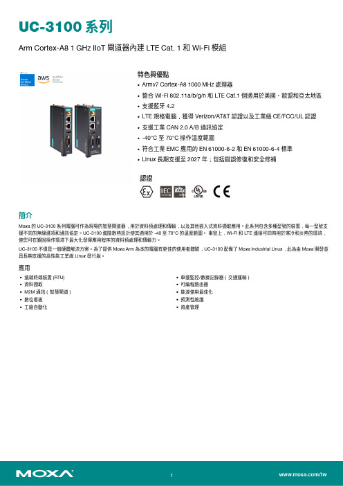
UC-3100系列Arm Cortex-A81GHz IIoT閘道器內建LTE Cat.1和Wi-Fi模組特色與優點•Armv7Cortex-A81000MHz處理器•整合Wi-Fi802.11a/b/g/n和LTE Cat.1個適用於美國、歐盟和亞太地區•支援藍牙4.2•LTE規格電腦,獲得Verizon/AT&T認證以及工業級CE/FCC/UL認證•支援工業CAN2.0A/B通訊協定•-40°C至70°C操作溫度範圍•符合工業EMC應用的EN61000-6-2和EN61000-6-4標準•Linux長期支援至2027年;包括錯誤修復和安全修補認證簡介Moxa的UC-3100系列電腦可作為現場的智慧閘道器,用於資料預處理和傳輸,以及其他嵌入式資料擷取應用。
此系列包含多種型號的裝置,每一型號支援不同的無線選項和通訊協定。
UC-3100進階散熱設計使其適用於-40至70°C的溫度範圍。
事實上,Wi-Fi和LTE連接可同時用於寒冷和炎熱的環境,使您可在艱困操作環境下最大化發揮應用程序的資料預處理和傳輸力。
UC-3100不僅是一個硬體解決方案。
為了提供Moxa Arm為本的電腦有更佳的使用者體驗,UC-3100配備了Moxa Industrial Linux,此為由Moxa開發並具長期支援的高性能工業級Linux發行版。
應用•遠端終端裝置(RTU)•資料擷取•M2M通訊(智慧閘道)•數位看板•工廠自動化•車載監控/數據記錄器(交通運輸)•可編程路由器•能源使用最佳化•預測性維護•資產管理外觀UC-3101UC-3121規格ComputerDRAM1GB DDR3Supported OS Linux Debian9(kernel4.4)Moxa Industrial LinuxSee /MILStorage Pre-installed8GB eMMCStorage Slot UC-3111/3121Models:SD slots x1Computer InterfaceTPM TPM v2.0Ethernet Ports Auto-sensing10/100Mbps ports(RJ45connector)x2Serial Ports UC-3101/3121Models:RS-232/422/485ports x1,software-selectable(DB9male)UC-3111Models:RS-232/422/485ports x2,software-selectable(DB9male) USB2.0USB2.0hosts x1,type-A connectorsCellular Antenna Connector SMA x2SIM Format NanoNumber of SIMs2GPS Antenna Connector SMA x1Wi-Fi Antenna Connector UC-3111/UC-3121Models:RP-SMA x2Console Port RS-232(TxD,RxD,GND),4-pin header output(115200,n,8,1)Ethernet InterfaceMagnetic Isolation Protection 1.5kV(built-in)Cellular InterfaceBand Options US Models:LTE Bands:Band2(1900MHz)/Band4(1700MHz)/Band5(850MHz)/Band12(700MHz)/Band13(700MHz)/Band14(700MHz)/Band66(1700MHz)/Band71(600MHz)UMTS Bands:2(1900MHz)/Band4(1700MHz)/Band5(850MHz)Carrier Approval:Verizon,AT&TEU Models:LTE Bands:Band1(2100MHz)/Band3(1800MHz)/Band7(2600MHz)/Band8(900MHz)/Band20(800MHz)/Band28A(700MHz)UMTS Bands:Band1(2100MHz)/Band3(1800MHz)Band8(900MHz)AP Models:LTE Bands:Band1(2100MHz)/3(1800MHz)/Band5(850MHz)/Band8(900MHz)/Band9(1700MHz)/Band18(850MHz)/Band19(850MHz)/Band26(850MHz)/Band28(700MHz)UMTS Bands:1(2100MHz)/Band5(850MHz)/Band6(800MHz)/Band8(900MHz)/Band19(800MHz)WLAN InterfaceWLAN Standards UC-3111-T-LX/UC-3121-T-LX Models:802.11a/b/g/n,Bluetooth4.2compliance Frequency Band UC-3111-T-LX/UC-3121-T-LX Models:2.4GHz/5GHzSerial InterfaceData Bits5,6,7,8Parity None,Even,Odd,Space,MarkStop Bits1,1.5,2Baudrate50bps to921.60kbpsSerial SignalsRS-232TxD,RxD,RTS,CTS,DTR,DSR,DCD,GNDRS-422Tx+,Tx-,Rx+,Rx-,GNDRS-485-2w Data+,Data-,GNDRS-485-4w Tx+,Tx-,Rx+,Rx-,GNDCAN InterfaceBaudrate UC-3121-T-US-LX/UC-3121-T-EU-LX/UC-3121-T-AP-LX:10to1000kbpsConnector UC-3121-T-US-LX/UC-3121-T-EU-LX/UC-3121-T-AP-LX:DB9maleIsolation UC-3121-T-US-LX/UC-3121-T-EU-LX/UC-3121-T-AP-LX:2kV(built-in)Signals UC-3121-T-US-LX/UC-3121-T-EU-LX/UC-3121-T-AP-LX:CAN_H,CAN_L,CAN_GND,CAN_SHLD,CAN_V+,GNDLED IndicatorsSystem Power x1CAN UC-3121-T-US-LX/UC-3121-T-EU-LX/UC-3121-T-AP-LX:1per port(Tx,Rx)Serial1per port(Tx,Rx)LAN1per port(10/100Mbps)Wireless Signal Strength UC-3101Models:Cellular x3UC-3111/UC-3121Models:Cellular x3and Wi-Fi x3Power ParametersInput Current500mA@12VDCInput Voltage9to36VDCPower Consumption UC-3101Models:6W(Max)UC-3111/UC-3121Models:8W(Max)Physical CharacteristicsHousing MetalInstallation DIN-rail mountingWall mounting(with optional kit)Dimensions(without ears)UC-3101Models:128.5x89.1x26mm(5.06x3.51x1.02in)UC-3111/UC-3121Models:128.5x89.1x41mm(5.06x3.51x1.61in)Weight Product only:550g(1.22lb)Environmental LimitsOperating Temperature-40to70°C(-40to158°F)Storage Temperature(package included)-40to85°C(-40to185°F)Ambient Relative Humidity5to95%(non-condensing)Vibration5Grms@IEC60068-2-64,random wave,5-500Hz,1hr per axis(without USB devicesattached)Shock IEC60068-2-27Standards and CertificationsEMC EN61000-6-2/-6-4EN55032/35EMI CISPR32,FCC Part15B Class AEMS IEC61000-4-2ESD:Contact:4kV;Air:8kVIEC61000-4-3RS:80MHz to1GHz:10V/mIEC61000-4-4EFT:Power:2kV;Signal:1kVIEC61000-4-5Surge:Power:0.5kV;Signal:1kVIEC61000-4-6CS:10VIEC61000-4-8PFMFCarrier Approvals UC-3101-T-US-LX:AT&T,VerizonUC-3111-T-US-LX/-T-US-LX-NW:AT&T,VerizonUC-3121-T-US-LX:AT&T,VerizonCellular Standards EN301511EN301908-1EN62311(MPE SAR)EN301489-1/-52EN301489-1/17Radio Frequency FCCPTCRBRCMIFETEL(UC-3111-T-US-LX)ENACOM(UC-3111-T-EU-LX)NBTC(UC-3111-T-EU-LX)SUBTEL(UC-3111-T-EU-LX)Safety IEC60950-1UL60950-1IEC62368-1UL62368-1NOM(UC-3111-T-US-LX)WLAN Standards EN301489-1-17EN300328EN301893Green Product RoHS,CRoHS,WEEEHazardous Locations Class I Division2ATEXIECExMTBFTime UC-3101-T-US-LX:702,846hrsUC-3101-T-EU-LX/T-AP-LX:585,775hrsUC-3111-T-US-LX:465,569hrsUC-3111-T-EU-LX/T-AP-LX:416,081hrsUC-3121-T-US-LX:474,796hrsUC-3121-T-EU-LX/T-AP-LX:428,931hrs Standards Telcordia(Bellcore)StandardWarrantyWarranty Period5yearsDetails See /tw/warranty Package ContentsDevice1x UC-3100Series computerCable1x terminal block to power jack converter Documentation1x quick installation guide1x warranty card尺寸UC-3101UC-3111UC-3121訂購資訊Model NameCarrier Approval CPUSD SlotRAMeMMCSerialTPM 2.0CANLTEWi-FiBLTUC-3101-T-US-LX AT&T,Verizon 1GHz –1GB 8GB 1P –Cat.1––UC-3111-T-US-LX AT&T,Verizon 1GHz 11GB 8GB 2P –Cat.1P PUC-3111-T-US-LX-NW AT&T,Verizon 1GHz 11GB 8GB 2P –Cat.1––UC-3121-T-US-LX AT&T,Verizon 1GHz 11GB 8GB 1P 1Cat.1P P UC-3101-T-EU-LX –1GHz –1GB 8GB 1P –Cat.1––UC-3111-T-EU-LX –1GHz 11GB 8GB 2P –Cat.1P P UC-3111-T-EU-LX-NW –1GHz 11GB 8GB 2P –Cat.1––UC-3121-T-EU-LX –1GHz 11GB 8GB 1P 1Cat.1P P UC-3101-T-AP-LX –1GHz –1GB 8GB 1P –Cat.1––UC-3111-T-AP-LX –1GHz 11GB 8GB 2P –Cat.1P P UC-3111-T-AP-LX-NW –1GHz 11GB 8GB 2P –Cat.1––UC-3121-T-AP-LX–1GHz11GB8GB1P1Cat.1PP配件(選購)Power AdaptersPWR-12150-CN-SA-TLocking barrel plug,12VDC,1.5A,100to 240VAC,China (CN)plug,-40to 75°C operating temperaturePWR-12150-EU-SA-T Locking barrel plug,12VDC,1.5A,100to240VAC,Continental Europe(EU)plug,-40to75°C operatingtemperaturePWR-12150-UK-SA-T Locking barrel plug,12VDC,1.5A,100to240VAC,United Kingdom(UK)plug,-40to75°C operatingtemperaturePWR-12150-AU-SA-T Locking barrel plug,12VDC,1.5A,100to240VAC,Australia(AU)plug,-40to75°C operatingtemperaturePWR-12150-USJP-SA-T Locking barrel plug,12VDC1.5A,100to240VAC,United States/Japan(US/JP)plug,-40to75°Coperating temperatureCablesCBL-F9DPF1x4-BK-100Console cable with4-pin connector,1mDIN-Rail Mounting KitsUC-3100DIN-Rail Kit DIN-rail kit with screwsWall-Mounting KitsUC-3100Wall-Mounting Kit Wall-mounting kit with screwsAntennasANT-LTE-ASM-02GPRS/EDGE/UMTS/HSPA/LTE,omni-directional rubber duck antenna,2dBiANT-WDB-ARM-02 2.4/5GHz,omni-directional rubber duck antenna,2dBi,RP-SMA(male)ANT-LTEUS-ASM-01GSM/GPRS/EDGE/UMTS/HSPA/LTE,omni-directional rubber duck antenna,1dBiUC-3100Antenna Set4dBi at1575MHz to1610MHz,SMA(male),active GPS/GLONASS,adhesive-type antenna with20-cmcable;2x4dBi at2.4GHz or5dBi at5GHz,RP-SMA(female),omnidirectional antennas;2x1.5dBi698to960MHz or1710to2700MHz,SMA(male),LTE,swivel-type omnidirectional portable antennas©Moxa Inc.版權所有.2023年3月07日更新。
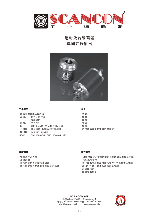
scancon编码器中文说明书
电流消耗
最大 :230 mA (10 V DC),最大:100 mA (24 V DC)
电气寿命
>105小 时
连接
连接 器 或 电 缆出口1m
* 电源电压 符 合EN 50 178标准 ( 安 全 的 超低电压)
机械数据
外壳 使用寿命 轴负载 转子惯量 启动转矩 RPM (连续操作) 冲击 (EN 60068-2-27) 持久的冲击 (EN 60028-2-29) 振动 (EN 60068-2-6) 重量,多圈 法兰 轴径 轴长或空心轴深度
66
工
业
编
码
器
绝对旋转编码器 单圈并行输出
机械图纸 同步法兰 2种 型 号 可 选
电缆出口 (~Ø10 mm)
同步法兰 S06型 S10型
直 径[ m m ] Ø6f6 Ø10h8
长 度[mm] 10 20
* 不锈钢
长
单圈
轴向 径向
并行 42 53
并行预设 53 53
连接器出口 ( 仅 适 用于大于13位产品,配备M27x1轴 向 连 接 器)
1 6针 连 接 器 ( 公 头 )
2 6针 连 接 器 ( 公 头 )
补码-输 入 功能
旋转方向 转换时间 < 3 µs 预 设-输 入 ( 可 选) 功能 预设
锁 存-输入( 可 选 ) 功能 锁存 锁存时间 < 3 µs * 锁存时间
等级
0(输入 = N.C.* 或 GND) 1( 输 入 + Ub 或 ≥ 4 . 5 V)
绝对旋转编码器 单圈并行输出
压紧扭矩支架
* 不锈钢
最大 宽度**= 30 最 小宽度** = 15 * *空 心 轴 深 度
POSITAL编码器说明书

P O S I T A L编码器说明书 Prepared on 24 November 2020POSITAL编码器资料FRABA 编码器德国博思特POSITAL编码器、POSITAL工业编码器、POSITAL倾角仪,POSITAL传感器、POSITAL线性传感器,POSITAL绝对值编码器、POSITAL旋转编码器等。
编码器行业领导者上海精芬德国博思特POSITAL编码器、POSITAL工业编码器、POSITAL倾角仪,POSITAL 传感器、POSITAL线性传感器,POSITAL绝对值编码器、POSITAL旋转编码器等,如需询价或详细信息,方案选型与精芬联系。
德国POSITAL公司成立于1918年,致力于高端机电产品的研发及生产,是欧洲绝对值编码器产品的领跑者。
该公司产品广泛应用于冶金、汽车制造、水利、物流、机械制造、木材加工、造船等行业。
以下021列举部分型号:OCD-S200G-1412-B15S-PRL、OCD-S200G-1212-B150-PRL、OCD-S200G-1212-B15S-CRW、OCD-S200G-1213-B150-CAW、OCD-S200B-1213-SA1C-CRS-150、OCD-S200G-1416-S060-PRL、OCD-S200G-1213-B15C-CAS-182、OCD-S200G-1416-S100-CAW、OCD-S200G-1212-C100-PRL、OCD-S200G-1412-B150-PRL、OCD-S100G-1212-B150-PAL、OCD-S100G-0012-C100-PRL、OCD-S100G-1212-C10S-CRW-5m、OCD-S100G-1212-S100-PRL、OCD-S100G-1212-B15V-CAW-5m、OCD-S100G-0013-S100-PRL、OCD-S100G-1212-S10S-PRL、OCD-S100G-0016-S10S-PAL、OCD-S100B-1212-C10S-PRL、OCD-S100G-1416-C100-PRL、OCD-S100G-1213-C100-PA9、OCD-S100G-1213-C100-PAL、OCD-S100G-1212-S060-PRL-050、OCD-S100G-1212-B150-PRL、OCD-S100G-1213-C100-PRL、OCD-S100B-0016-B15S-CRW-136、OCD-S100G-1212-C100-PRL、OCD-S100G-1212-C100-CRW、OCD-S100G-1212-S060-PAL、OCD-S100B-0016-S060-PAL-135、OCD-S100G-0013-C100-PAL OCD-S100G-1213-T120-PRL、OCD-S100B-1212-S060-CRW、OCD-S100G-0016-T12C-CRW-163、OCD-S100G-1416-C10V-CAW-5m、OCD-S100G-1216-S10S-PRL、OCD-S100G-0016-T120-CRW、OCD-S100B-1212-C100-PRL、OCD-S100B-1212-B15V-CAW-5m、OCD-S100G-1212-B15S-PAL、OCD-S100B-0016-C100-CAW-5m、OCD-S100G-1212-C10S-PRL、OCD-S100B-0016-T120-CRW、OCD-S100G-1213-S10S-PRL、OCD-S100B-1213-C10S-PRL、OCD-S100G-0013-S060-PRL、OCD-S100B-0016-T120-PRL、OCD-SL00G-1213-SA1C-CRS-159、OCD-S100B-0016-B150-CRW、OCD-S100G-1212-S10V-PAL、OCD-S100B-0012-C100-PAL、OCD-S100G-1212-S100-CRW-10m、OCD-S100G-1212-B15S-PRL、OCD-S100B-1416-C100-CRW、OCD-S100G-1212-S060-CRW、OCD-S100B-12AJ-C10C-PRL-204、OCD-S100G-1213-S060-PAL、OCD-S100G-0013-C10C-PRL-050、OCD-S100B-1212-B15S-CRW-5m、OCD-S100G-1212-T120-PRL、OCD-S100G-0016-C10S-PRL、OCD-S100G-1213-S060-PRL、OCD-S100G-1213-B150-PRL、OCD-S100G-1213-C10C-PRL-050、OCD-S100G-1408-S10V-PAL、OCD-S100B-1212-B15S-CRW-10m、OCD-S100B-0013-S060-PAL、OCD-S100G-1213-B15S-PRL、OCD-S100G-1216-C10S-PRL、OCD-S100B-1416-B150-PRL、OCD-S100B-0016-S060-CAW、OCD-S100G-1212-S060-PRL、OCD-S100G-1212-C100-PAL、OCD-S100G-0013-C100-PRL、OCD-S100B-1213-B15V-PRL、OCD-S100B-0016-S060-PAL、OCD-SS00G-1412-C10S-PRL、OCD-SS00G-1212-C10S-PRL、OCD-SS00G-1212-C100-PRL、OCD-SS00G-1212-C100-CRB、OCD-SS00G-1212-C066-PA5、OCD-SS00G-1212-S06C-CRW-148、OCD-SS00G-0812-C106-PAL、OCD-SS00E-00AB-C066-PAB、OCD-SS00G-1212-C100-PR5、OCD-SS00G-0012-C106-PAB、OCD-SS00G-0412-C066-PRL、OCD-SS00G-0412-C066-PR5、OCD-SS00G-1212-C100-PAB、OCD-SS00G-0012-S06S-PRL、OCD-SS00G-0812-C066-PR5、OCD-SL00G-1212-C10V-CAW、OCD-SL00G-1213-S060-PAL-023、OCD-SL00G-1212-C10S-PAL、OCD-SL00G-0013-S060-CRS-010、OCD-SL00G-0812-C100-CRW、OCD-SL00B-0012-C100-PAL、OCD-SL00G-1212-C100-CRW-5m、OCD-SL00G-0016-C10S-CRW-097、OCD-SL00G-1213-SA5C-CRO-066、OCD-SL00G-1416-C100-PRL、OCD-SL00G-1214-C100-PRL-099、OCD-SL00G-0016-S06S-CAW-052、OCD-SL00B-1212-C100-PAL-050、OCD-SL00G-1212-S100-PRL、OCD-SL00B-0013-B150-PRL、OCD-SL00G-1212-B15S-PRL、OCD-SL00G-1412-C100-PRL-B、OCD-SL00G-0013-C100-PRB、OCD-SL00G-1213-C100-PRL-099、OCD-SL00G-0016-C100-CAW、OCD-SL00G-1213-C10S-CRW-2M、OCD-SL00B-0013-SB10-PAL、OCD-SL00G-1212-S06S-PRL、OCD-SL00G-1212-C100-PRB、OCD-SL00B-0012-C100-PAL-050、OCD-SL00G-1213-S060-CRW、OCD-SL00B-0014-B150-CRW-2m、OCD-S101G-1212-C100-CRW-2、OCD-S101G-1213-C100-CRW-2m旗下品牌BEN选型BEN是专业生产编码器的跨国公司,主要产品有绝对值编码器,增量和防爆编码器,BEN编码器总部在德国柏林,公司在欧洲、美洲和亚洲设有许多分支机构和代表处,是真正的国际性企业。
亚历山大-伯兰迪 8位灰码编码器输入模块说明书

1AllenĆBradleyGray Encoder (12Ć24 VDC)Input Module (Cat. No. 1771-DL)Product Data The Gray Encoder (12-24 VDC) Input Module converts an 8-bit Gray codefrom an absolute encoder to an 8-bit binary number for input to anAllen-Bradley programmable controller.The module also has a 120 V AC zero-speed triac switch which is on whilethe Gray encoder is in motion. The switch turns off after a selectable delaywhen the module detects that motion has stopped. You can use this switchas a safety interlock to open the drive circuit after motion stops or if theencoder should fail.The Allen-Bradley 8-bit Gray Encoder (Bulletin 845A-SJZ3DN6DW iscompatible with this encoder module.The encoder module is shipped with wiring arm (cat. no. 1771-WB).Description2The module receives its inputs from an encoder that detects rotational position, 0-360°, and converts position values to a corresponding 8-bit Gray code, 0-255. The encoder transmits coded position values to the module over a multiconductor cable (figure 1).Figure 1Block Diagram of Encoder and ModuleModule OutputsThe module converts 8-bit Gray code to 8-bit binary, and places these values on the backplane of the I/O chassis. The processor or remote I/O adapter reads these values in the same manner it reads data from a discrete I/O module. Values are read into the processor’s input image table word address corresponding to the module’s location in the I/O chassis: upper byte for slot 1, lower byte for slot 0.Zero Speed SwitchThe encoder module has a zero-speed triac switch (between terminals 11 and 12) which remains on until the module detects that motion has stopped.An adjustable time delay opens the switch after a delay. You adjust the delay time between 0.3 and 6.0 seconds using the trim pot located under the zero-speed indicator on the front of the module: counter-clockwise for shorter delay, clockwise for longer delay. It is factory set for 6.0 seconds.Module Inputs3The switch is rated at 0.5 A at 120 V AC, 47-63 Hz. Use this switch only toopen a “sealed-in” circuit (figure 2) such as for a motor starter. Do not useto initiate a “sealed-in” circuit.Figure 2Zero Speed Switch CircuitYou may need additional surge suppression to protect the triac switch fromthe motor starter. A load with large inductive characteristics can generatevoltage transients which exceed the switch’s internal surge current rating.Since switching frequency and load impedance vary with application, wecannot specify a particular suppressor for your motor starter. The tablebelow offers some suggestions for selecting a suppressor.The module has a 1 A fuse located on the circuit board inside the module.This fuse is in series with the triac switch, and will blow if the maximumsurge current exceeds 2 A for 10 ms.4Electrostatic DamageUnder some conditions, electrostatic discharge can degrade performance or damage the module. If you observe the following precautions you can guard against electrostatic damage.Touch a grounded object to discharge yourself before handling themodule.Do not touch the backplane connector or connector pins.When replacing the fuse, do not touch other circuit components inside the module. If available, use a static-safe work station.Replacing the FuseReplace the fuse as follows:Remove cover by unscrewing four corner screws.Remove the circuit board and turn it over.Locate the fuse on the lower side, and replace.Re-assemble in reverse order.Status IndicatorsThe front panel of the encoder module contains nine red LED status indicators.The top indicator lights when the zero-speed triac switch is ON. Each of the remaining eight indicators corresponds to a single Gray code bit, and lights when the logic state of the bit is OFF.The encoder module requires 120 mA from the I/O chassis power supply. Total this amount with the current requirements of other modules in the chassis to guard against overloading the backplane and backplane power supply.Backplane Power5Customer Power SupplyThe module also requires a 12 to 24 VDC power supply which you connect to the wiring arm and absolute encoder (figure 3). The encoder driving circuit sinks 15 mA at 24 VDC or 6 mA at 12 VDC per Gray code input.Multiply this by eight for each encoder powered by this supply. Some absolute encoders may require an additional 5 VDC supply.Figure 3Wiring Diagram Use Belden 9556 multiconductor shielded cable (or equivalent) to connectthe encoder to the module’s wiring arm (figure 3). Ground the cable at oneend, only. We recommend that you ground it at an I/O chassis mountingstud. Wrap the drain wire and shield together and connect both to themounting stud. Limit the cable length to 50 feet.Wiring6WARNING: Remove power from the 1771 I/O chassisbackplane and wiring arm before removing or installing an I/Omodule.Failure to remove power from the backplane or wiring armcould cause module damage, degradation of performance, orinjury.Failure to remove power from the backplane could causeinjury or equipment damage due to possible unexpectedoperation.Plastic keying bands are shipped with each I/O chassis. These bands help ensure that only a selected type of module can be placed in a particular module slot. They also help to align the module with the backplane connector.Each module is slotted at its rear edge. The position of the keying bands on the upper backplane connector must correspond to these slots to allow insertion of the module. For the 1771-DL Gray Encoder Module, position the keying bands as follows:Between 4 and 6Between 24 and 26Keying7Input G one 8Ćbit Absolute Gray Encoder Digital Resolution G 1 part in 256HighĆtrue Logic G from a 7406, 7407, or equivalent TTL circuit with an open collector output G module sources current to user device Logic State G logic 1: 10Ć27 VDC G logic 0 : 0Ć2 VDC Input Sourcing Current G 6 mA per bit at 10 VDC G 15 mA per bit at 27 VDC Input Filter Time Delay G 1 millisecond (max.)Backplane Current G 120 mA at 5 VDC ZeroĆSpeed Triac SwitchG output voltage:120 VAC (92Ć138 VAC,47Ć63 Hz)G output time delay:adjustable from 0.3 to 6.0seconds(factory set at 6 seconds)G continuous output current:0.5 A (max.)G maximum surge current:2 A for 10 msG minimum load current:50 mAG ON state" voltage drop:2V at 100 mA load currentG OFF state" leakage current:5 mA (max.)G output fuse:8 AG, 1 A normal blowEnvironmental ConditionsG operating temperature:0 to 60° C (32 to 140° F)G storage temperature:-40 to 85° C (-40 to 185° F)G relative humidity:5 to 95% (without condensation)Keying Band PositionsG between 4 and 6G between 24 and 26© 1986 Allen-Bradley CompanyPLC is a registered trademark of Allen-Bradley CompanySpecifications8With offices in major cities worldwideWORLD HEADQUARTERS Allen-Bradley 1201 South Second Street Milwaukee, WI 53204 USA Tel: (1) 414 382-2000Telex: 43 11 016FAX: (1) 414 382-4444EUROPE/MIDDLE EAST/AFRICA HEADQUARTERS Allen-Bradley Europe B.V .Amsterdamseweg 151422 AC Uithoorn The Netherlands Tel: (31) 2975/43500Telex: (844) 18042FAX: (31) 2975/60222ASIA/PACIFIC HEADQUARTERS Allen-Bradley (Hong Kong)Limited Room 1006, Block B, Sea View Estate 28 Watson Road Hong Kong Tel: (852) 887-4788Telex: (780) 64347FAX: (852) 510-9436CANADA HEADQUARTERS Allen-Bradley Canada Limited 135 Dundas Street Cambridge, Ontario N1R 5X1Canada Tel: (1) 519 623-1810FAX: (1) 519 623-8930LATIN AMERICA HEADQUARTERS Allen-Bradley 1201 South Second Street Milwaukee, WI 53204 USA Tel: (1) 414 382-2000Telex: 43 11 016FAX: (1) 414 382-2400As a subsidiary of Rockwell International, one of the world’s largest technology companies — Allen-Bradley meets today’s challenges of industrial automation with over 85 years of practical plant-floor experience. More than 11,000 employees throughout the world design, manufacture and apply a wide range of control and automation products and supporting services to help our customers continuously improve quality, productivity and time to market. These products and services not only control individual machines but integrate the manufacturing process, while providing access to vital plant floor data that can be used to support decision-making throughout the enterprise.Publication 1771-2.29 — June 1986Supersedes Publication 1771-941 — September 1981PN 955099-78Printed in USA。
【精品】测速编码器说明书

BEN测速编码器在智能车舵机控制中的应用2.1舵机工作原理舵机在6V电压下正常工作,而大赛组委会统一提供的标准电源输出电压为7.2V,则需一个外围电压转换电路将电源电压转换为舵机的工作电压6V。
图2为舵机供电电路。
舵机由舵盘、位置反馈电位计、减速齿轮组、直流动电机和控制电路组成,内部位置反馈减速齿轮组由直流电动机驱动,其输出轴带动一个具有线性比例特性的位置反馈电位器作为位置检测。
当电位器转角线性地转换为电压并反馈给控制电路时,控制电路将反馈信号与输入的控制脉冲信号相比较,产生纠正脉冲,控制并驱动直流电机正向或反向转动,使减速齿轮组输出的位置与期望值相符。
从而达到舵机精确控制转向角度的目的。
舵机工作原理框图如图3所示。
2.2舵机的安装与调节舵机的控制脉宽与转角在-45°~+45°范围内线性变化。
对于对速度有一定要求的智能车,舵机的响应速度和舵机的转向传动比直接影响车模能否以最佳速度顺利通过弯道。
车模在赛道上高速行驶,特别是对于前瞻性不够远的红外光电检测智能车,舵机的响应速度及其转向传动比将直接影响车模行驶的稳定性,因此必须细心调试,逐一解决。
由于舵机从执行转动指令到响应输出需占用一定的时间,因而产生舵机实时控制的滞后。
虽然车模在进入弯道时能够检测到黑色路线的偏转方向,但由于舵机的滞后性,使得车模在转弯过程中时常偏离跑道,且速度越快,偏离越远,极大限制车模在连续弯道上行驶的最大时速,使得车模全程赛道速度很难进一步提高。
为了减小舵机响应时间,在遵守比赛规则不允许改造舵机结构的前提下,利用杠杆原理,采用加长舵机力臂的方案来弥补这一缺陷,加长舵机力臂示意图如图4所示。
图4中,R为舵机力臂;θ为舵机转向角度;F为转向所需外力;α为外力同力臂的夹角。
在舵机输出盘上增加长方形杠杆,在杠杆的末端固定转向传动连杆,其表达式为:加长力臂后欲使前轮转动相同角度时,在舵机角速度ω相同的条件下舵机力臂加长后增大了线速度v,最终使得舵机的转向角度θ减小。
编码器使用说明

编码器使用说明光电编码器基础1.1 概述光电编码器是一种集光、机、电为一体的数字化检测装置,它具有分辨率高、精度高、结构简单、体积小、使用可靠、易于维护、性价比高等优点。
近10几年来,发展为一种成熟的多规格、高性能的系列工业化产品,在数控机床、机器人、雷达、光电经纬仪、地面指挥仪、高精度闭环调速系统、伺服系统等诸多领域中得到了广泛的应用。
光电编码器可以定义为:一种通过光电转换,将输至轴上的机械、几何位移量转换成脉冲或数字量的传感器,它主要用于速度或位置(角度)的检测。
典型的光电编码器由码盘(Disk)、检测光栅(Mask)、光电转换电路(包括光源、光敏器件、信号转换电路)、机械部件等组成。
一般来说,根据光电编码器产生脉冲的方式不同,可以分为增量式、绝对式以及复合式三大类。
按编码器运动部件的运动方式来分,可以分为旋转式和直线式两种。
由于直线式运动可以借助机械连接转变为旋转式运动,反之亦然。
因此,只有在那些结构形式和运动方式都有利于使用直线式光电编码器的场合才予使用。
旋转式光电编码器容易做成全封闭型式,易于实现小型化,传感长度较长,具有较长的环境适用能力,因而在实际工业生产中得到广泛的应用,在本书中主要针对旋转式光电编码器,如不特别说明,所提到的光电编码器则指旋转式光电编码器。
1.2 增量式光电编码器1.2.1 原理及其结构增量式光电编码器的特点是每产生一个输出脉冲信号就对应于一个增量位移,但是不能通过输出脉冲区别出在哪个位置上的增量。
它能够产生与位移增量等值的脉冲信号,其作用是提供一种对连续位移量离散化或增量化以及位移变化(速度)的传感方法,它是相对于某个基准点的相对位置增量,不能够直接检测出轴的绝对位置信息。
一般来说,增量式光电编码器输出A、B两相互差电度角的脉冲信号(即所谓的两组正交输出信号),从而可方便地判断出旋转方向。
同时还有用作参考零位的Z相标志(指示)脉冲信号,码盘每旋转一周,只发出一个标志信号。
编码器使用说明书
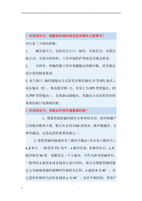
1.※有网友问:增量旋转编码器选型有哪些注意事项?应注意三方面的参数:1.械安装尺寸,包括定位止口,轴径,安装孔位;电缆出线方式;安装空间体积;工作环境防护等级是否满足要求。
2.分辨率,即编码器工作时每圈输出的脉冲数,是否满足设计使用精度要求。
3.电气接口,编码器输出方式常见有推拉输出(F型HTL格式),电压输出(E),集电极开路(C,常见C为NPN型管输出,C2为PNP型管输出),长线驱动器输出。
其输出方式应和其控制系统的接口电路相匹配。
2.※有网友问:请教如何使用增量编码器?1,增量型旋转编码器有分辨率的差异,使用每圈产生的脉冲数来计量,数目从6到5400或更高,脉冲数越多,分辨率越高;这是选型的重要依据之一。
2,增量型编码器通常有三路信号输出(差分有六路信号):A,B和Z,一般采用TTL电平,A脉冲在前,B脉冲在后,A,B脉冲相差90度,每圈发出一个Z脉冲,可作为参考机械零位。
一般利用A超前B或B超前A进行判向,我公司增量型编码器定义为轴端看编码器顺时针旋转为正转,A超前B为90°,反之逆时针旋转为反转B超前A为90°。
也有不相同的,要看产品说明。
3,使用PLC采集数据,可选用高速计数模块;使用工控机采集数据,可选用高速计数板卡;使用单片机采集数据,建议选用带光电耦合器的输入端口。
4,建议B脉冲做顺向(前向)脉冲,A脉冲做逆向(后向)脉冲,Z原点零位脉冲。
5,在电子装置中设立计数栈。
3.※关于户外使用或恶劣环境下使用有网友来email问,他的设备在野外使用,现场环境脏,而且怕撞坏编码器。
我公司有铝合金(特殊要求可做不锈钢材质)密封保护外壳,双重轴承重载型编码器,放在户外不怕脏,钢厂、重型设备里都可以用。
不过如果编码器安装部分有空间,我还是建议在编码器外部再加装一防护壳,以加强对其进行保护,必竟编码器属精密元件,一台编码器和一个防护壳的价值比较还是有一定差距的。
4.※从接近开关、光电开关到旋转编码器:工业控制中的定位,接近开关、光电开关的应用已经相当成熟了,而且很好用。
Baumer 多轴编码器说明书

Absolute encoders - modular bus coversb j ec t t o m od i fi c a t i o n i n te c h n i c a n d d e s i g n . E r r o r s a n d o m i s s i o n s e x c e p t e d .GBMMW with modular bus cover Features–Encoder multiturn / bus cover –Optical sensing method –Total resolution up to 31 bit –Clamping or synchro flange–High resistance to shock and vibrations –CANopen®/DeviceNet/EtherCAT/EtherNet-IP SAEJ1939/PROFINET/POWERLINK/Profibus/SSI –Code continuity check optional by bus –Maximum resistant against magnetic fieldsTechnical data - electrical ratings Voltage supply 10...30 VDC Reverse polarity protection YesConsumption w/o load ≤100 mA (24 VDC)Initializing time typ.250 ms after power onInterfacesCANopen®, DeviceNet,EtherCAT, EtherNet/IP , Profibus, PROFINET, POWERLINK, SAE J1939, SSI Function MultiturnDevice adress Rotary switches in bus cover Steps per revolution ≤262144 / 18 bit Number of revolutions ≤8192 / 13 bit Absolute accuracy ±0.01 °Sensing method Optical CodeBinaryCode sequence CW/CCW programmable Interference immunity DIN EN 61000-6-2Emitted interference DIN EN 61000-6-4Programmable parametersSteps per revolution Number of revolutions Preset ScalingRotating directionDiagnostic functions Position or parameter error Multiturn sensingStatus indicator DUO-LED integrated in bus coverApprovalUL approval / E63076GBMMWTechnical data - mechanical design Size (flange)ø58 mmShaft typeø10 mm solid shaft (clamping flange)ø6 mm solid shaft (synchro flange)FlangeClamping or synchro flange Protection DIN EN 60529IP 54 (without shaft seal), IP 65 (with shaft seal)Operating speed ≤10000 rpm (mechanical) ≤6000 rpm (electric)Starting acceleration ≤1000 U/s²Starting torque ≤0.015 Nm (+25 °C, IP 54) ≤0.03 Nm (+25 °C, IP 65)Rotor moment of inertia 20 gcm²Admitted shaft load≤20 N axial ≤40 N radialMaterials Housing: steel Flange: aluminiumBus cover: zinc die-cast Operating temperature -25...+85 °C-40...+85 °C (optional)Relative humidity 95 % non-condensing Resistance DIN EN 60068-2-6Vibration 10 g, 16-2000 Hz DIN EN 60068-2-27 Shock 200 g, 6 ms Weight approx.600 g ConnectionBus coverHigh resolution, solid shaftOptical multiturn encoders 18 bit ST / 13 bit MTAbsolute encoders - modular bus coversb j ec t t o m od i fi c a t i o n i n te c h n i c a n d d e s i g n . E r r o r s a n d o m i s s i o n s e x c e p t e d .GBMMWPart number GBMMW.20Interface3P32Profibus-DPV0 / cable gland3PA2Profibus-DPV0 / connector M123V32Profibus-DPV2 / cable gland3VA2Profibus-DPV2 / connector M123EA2PROFINET / connector M12 EPA6EtherCAT / connector M12 8EA2EtherNet/IP / connector M125EA4POWERLINK / connector M125P32CANopen® / cable gland 5PA2CANopen® / connector M12 8P22DeviceNet / cable gland 8PA2DeviceNet / connector M12 2PA2SSI / connector M12 5B32SAEJ1939 / cable gland 5BA2SAEJ1939 / connector M12Flange / Solid shaft0Clamping flange / ø10 mm, IP 54 A Clamping flange / ø10 mm, IP 65 1Synchro flange / ø6 mm, IP 54BSynchro flange / ø6 mm, IP 65High resolution, solid shaftOptical multiturn encoders 18 bit ST / 13 bit MTAccessoriesConnectors and cables11034355Cable connector M12, 4-pin, on both sides, D-coded, 5 m cable (Z 185.E05)11034304Female connector M12, 8-pin, straight, 2 m cable (Z 174.003)11034305Female connector M12, 8-pin, straight, 5 m cable (Z 174.005)Mounting accessories 10117669Eccentric fixing, single (Z 119.006)10141255Adaptor plate for clamping flange formodification into synchro flange (Z 119.013)10117667Mounting adaptor for encoders with synchro flange (Z 119.015)10125051Mounting adaptor for encoders with clamping flange (M3) (Z 119.017)10158124Bearing flange for encoders with synchro flange (Z 119.035)10141132Spring washer coupling D1=6 / D2=10 (Z 121.C01)Programming accessories 10146710CD with describing files & manuals (Z 150.022)11034193Programming cable for encoders with SSI bus cover, CD with software and manual (Z 139.008)CD with file descriptions is not included in the delivery.You may order them on CD as accessory under part number Z 150.022.Absolute encoders - modular bus coversj e c t t o m o d i fi c a t i o n i n t e c h n i c a n d d e s i g n . E r r o r s a n d o m i s s i o n s e x c e p t e d .GBMMWHigh resolution, solid shaftOptical multiturn encoders 18 bit ST / 13 bit MTDimensionsGBMMW - synchro flangeProfibus-DP/CANopen®Profibus-DP - M12DeviceNetCANopen®/DeviceNet M12EtherCAT/EtherNet-IPPROFINET/POWERLINKSAEJ1939SAEJ1939 - M12GBMMW - clamping flange。
OCD-CAA1B-1213-C10S-H3P编码器

OCD-CAA1B-1213-C10S-H3P 编码器简介应用行业: 一. BEN 绝对值编码器的常规外形:38MM,58MM,66MM,80MM.100MM.二. BEN 绝对值编码器分为:单圈,多圈。
三. BEN 绝对值编码器按原理分为:磁绝对值编码器,光电绝对值编码器四. BEN 绝对值编码器出线方式分为:侧出线,后出线五. BEN 绝对值编码器轴分为:6MM,8MM,10MM,12MM,14MM,25MM.六.BEN 绝对值编码器分为:轴,盲孔,通孔。
七. BEN 绝对值编码器防护分为:IP54-68.八. BEN 绝对值编码器安装方式分为:夹紧法兰、同步法兰、夹紧带同步法兰、盲孔(弹簧片,抱紧)、通孔(弹簧片,键销)九. BEN 绝对值编码器精度分为:单圈精度和多圈精度,加起来是总精度,也就是通常的多少位(常规24位,25位,30位,32位。
)。
十. BEN 绝对值编码器通讯协议波特率:4800~115200 bit/s,默认为9600 bit/s。
刷新周期约1.5ms ★精芬机电传感器 * 机床 * 航天航空、 * 造纸印刷、 * 水利闸门、 * 纺织机械 * 灌溉机械 * 军工设备 * 食品机械 * 钢铁冶金设备 * 机器人及机械手臂 * 港口起重运输机械 * 精密测量和数控设备OCD-CAA1B-1213-C10S-H3P 编码器外形尺寸OCD-CAA1B-1213-C10S-H3P编码器技术参数BEN编码器的发展,从增量值编码器以转动时输出脉冲,通过计数设备来计算其位置,当编码器不动或停电时,依靠计数设备的内部记忆来记住位置。
这样,当停电后,编码器不能有任何的移动,当来电工作时,编码器输出脉冲过程中,也不能有干扰而丢失脉冲,不然,计数设备计算并记忆的零点就会偏移,而且这种偏移的量是无从知道的,只有错误的生产结果出现后才能知道。
解决的方法是增加参考点,编码器每经过参考点,将参考位置修正进计数设备的记忆位置。
矿业旋转编码器使用说明书
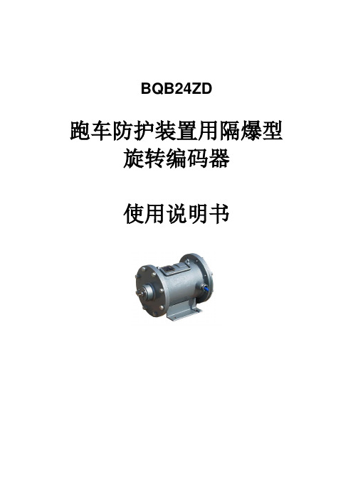
BQB24ZD跑车防护装置用隔爆型旋转编码器使用说明书目录1 用途 (3)2 环境条件 (3)3 主要技术参数 (3)4 产品分类 (3)4.1 型式 (3)4.2 产品型号 (3)5 产品结构及原理 (4)5.1 产品结构及外形尺寸 (4)5.2 电气原理 (4)6 安装、调试、操作及使用注意事项 (4)6.1 安装 (4)6.2 配接设备 (4)6.3 用户接线 (5)6.4 注意事项 (5)7 运输和储存 (5)8 订货和服务 (6)附录A ....................................................................... 错误!未定义书签。
使用旋转编码器前,请详细阅读本说明书。
1 用途BQB24ZD跑车防护装置用隔爆型旋转编码器(以下简称编码器)主要用于测量煤矿井下提升机转速及提升机与矿车之间的位移(或距离)关系。
旋转编码器选用集光、机、电技术于一体的数字化传感器,输出计数脉冲,可与多种PLC 进行连接换算。
编码器执行标准GB3836-2000、Q/ZMD021-2010。
2 环境条件——温度: 0℃~40℃;——平均相对湿度: ≤95%RH(+25℃);——大气压力: 80kPa~106kPa;——机械环境: 无显著振动和冲击的场合;——适用于有瓦斯和煤尘爆炸的危险环境中;——周围介质无腐蚀性气体。
3 主要技术参数供电电压:DC24V供电电流:350 mA4 产品分类4.1 型式矿用隔爆型“Exd I”。
4.2 产品型号B Q B 24 ZD跑车防护装置额定工作电压,V隔爆型保护设备:编码器5 产品结构及原理5.1 产品结构及外形尺寸编码器主要由进口旋转编码器、外壳两部分组成,其外部结构如图1所示。
图1外部结构及尺寸图5.2 电气原理5.2.1电气原理绝对编码器光码盘上有许多道刻线,每道刻线依次以2线、4线、8线、16线。
编排,这样,在编码器的每一个位置,通过读取每道刻线的通、暗,获得一组从2的零次方到2的n-1次方的唯一的2进制编码(格雷码),这就称为n位绝对编码器。
海湾电子编码器使用说明书
海湾电子编码器安装使用说明书一、概述GST-BMQ-2电子编码器(以下简称编码器)可对电子编码的探测器或模块进行地址码、灵敏度、设备类型等的读出和地址码、灵敏度的写入功能,还可以对火灾显示盘进行地址码、灯号及二次码的读出和写入。
二、特点1. 该编码器采用手握式结构,外形小巧,携带方便,操作简单;2. 该编码器可通过编码器后盖的总线接口,直接和总线型探测器旋接,进行编码等操作,更加方便,如图2所示(略);3. 可对公司生产的总线型探测器、模块等设备编码,可对ZF-GST8903火灾显示盘、JTY-HM-GST102线型光束感烟火灾探测器、JTY-HF-GST102线型光束感烟火灾探测器、隔爆点型可燃气体探测器等I²C接口设备编码;4. 四位段码式液晶显示,显示直观;5. 低功耗睡眠和自动关机功能;6. 电池欠压指示功能三、技术特性1. 电源:1节9V叠式电池2. 工作电流≤8mA3. 待机电流≤100чA4. 使用环境:温度:-10℃~+50℃相对湿度≤95%,不凝露5. 尺寸:164mm×64mm×37mm四、结构特征外形示意图如图1所示(略)1:电源开关 2:液晶屏3:总线插口 4:火灾显示盘接口(I²C)5:复位键 6:固定螺丝7:电池盒后盖 8:铭牌9:JTY-GD-G3、JTY-ZCD-G3N探测器总线接口10:JTY-GM-GST9611、JTW-ZOM-GST9612型探测器总线接口11:电池盒后盖螺丝 12:保护盖其中各部分名称和功能说明如下:1. 电源开关:完成系统硬件开机和关机操作。
2. 液晶屏:显示有关探测器的一切信息和操作人员输入的相关信息,并且当电源欠压时给出指示。
3. 总线插口:编码器通过总线插口与探测器或模块相连。
4. 火灾显示盘接口(I²C):编码器通过此接口与ZF-GST8903火灾显示盘或以I²C编程方式编码的探测器相连。
- 1、下载文档前请自行甄别文档内容的完整性,平台不提供额外的编辑、内容补充、找答案等附加服务。
- 2、"仅部分预览"的文档,不可在线预览部分如存在完整性等问题,可反馈申请退款(可完整预览的文档不适用该条件!)。
- 3、如文档侵犯您的权益,请联系客服反馈,我们会尽快为您处理(人工客服工作时间:9:00-18:30)。
SCM-CA00B-1213-C100-CAW编码器
BEN总公司在德国柏林,BEN编码器在欧洲、美洲和亚洲设有许多分支机构和代表处,是真正的国际性企业。
BEN编码器生产基地在法国马赛 MARSEILLES,中文名:倍恩,上海精芬机电是中国大陆地区唯一代理商,BEN旗下JFSH公司介绍SAG系列其余型号
SCM-CA00B-1213-C100-CAW编码器技术参数
SCM-CA00B-1213-C100-CAW编码器简介应用行业
一. 编码器速度:500 r/min~40000 r/min
二. 编码器温度:-60℃~+120℃可选
三. BEN编码器防护分为:IP54-IP68
四. BEN编码器分为:实心轴,盲孔,通孔
五. 编码器功能:精确检测角度,位置,速度,圈数...
六. 编码器的常规外形:18MM,38MM,58MM,66MM,80MM.100MM
七. BEN编码器分为:增量型,绝对值型(单圈,多圈)
八. BEN编码器按原理分为:磁编码器,光电编码器
九. BEN编码器出线方式分为:侧出线,后出线
十. BEN绝对值编码器轴分为:6MM,8MM,10MM,12MM,14MM,25MM
十一. BEN编码器安装方式分为:夹紧法兰、同步法兰、加紧带同步法兰、盲孔(弹簧片,抱紧)、通孔(弹簧片,键销)
十二. BEN绝对值编码器精度分为:单圈精度和多圈精度,加起来就是通常说的多少位(常规单圈10位,12位,13位,16位,20位,多圈24为,25为,30位,32位……)
十三. BEN编码器通讯协议波特率:4800~,9600,19200,115200bit/s,默认为9600bit/s。
刷新周期约1.2ms
十四. BEN绝对值编码器输出可选:SSI、4-20MA、0-10V,profibus-dp、DEVicenet、并行、二进制码、、BiSS、ISI、CANopen、Endat及Hiperface等
十五. BEN编码器常用规格:BESM58、BE1322SM58-N011、BE122SM58、BE1822SM58、BE420SM58,BE1622SM58-N011等★精芬机电传感器
*机床
*航天航空、
*造纸印刷、
*水利闸门、
* 纺织机械
* 灌溉机械
* 军工设备
* 食品机械
*钢铁冶金设备
* 机器人及机械手臂*港口起重运输机械*精密测量和数控设备
SCM-CA00B-1213-C100-CAW编码器介绍
旋转编码器是集光机电技术于一体的速度位移传感器。
当旋转编码器轴带动光栅盘旋转时,经发光元件发出的光被光栅盘狭缝切割成断续光线,并被接收元件接收产生初始信号。
该信号经后继电路处理后,输出脉冲或代码信号。
其特点是体积小,重量轻,品种多,功能全,频响高,分辨能力高,力矩小,耗能低,性能稳定,可靠使用寿命长等特点。
进口增量式编码器
增量式编码器轴旋转时,有相应的相位输出。
其旋转方向的判别和脉冲数量的增减,需借助后部的判向电路和计数器来实现。
其计数起点可任意设定,并可实现多圈的无限累加和测量。
还可以把每转发出一个脉冲的Z信号,作为参考机械零位。
当脉冲已固定,而需要提高分辨率时,可利用带90度相位差A,B的两路信号,对原脉冲数进行倍频。
进口绝对值编码器
绝对值编码器轴旋转器时,有与位置一一对应的代码(二进制,BCD码等)输出,从代码大小的变更即可判别正反方向和位移所处的位置,而无需判向电路。
它有一个绝对零位代码,当停电或关机后再开机重新测量时,仍可准确地读出停电或关机位置地代码,并准确地找到零位代码。
一般情况下绝对值编码器的测量范围为0~360度,但特殊型号也可实现多圈测量。
在工业自动化和运动控制领域,性能最优化很大程度上影响着用户对于编码器技术的选择。
通过本文,我们概括总结了光电编码器、旋转变压器以及磁式编码器的不同,阐述了为什么磁式BEN编码器在很多应用上更可取的原因。
本文同时向您介绍铁姆肯公司磁式编码器如何利用专利的霍尔效应技术以帮助达到精度和可靠性的最大化。
介绍随着自动化工业领域的迅速延伸,市场对于性能卓越的伺服系统需求越来越高。
工业自动化广泛应用于包装、纸张处理、电力发电等一些具有高温、粉尘、潮湿及强烈震动的特殊环境。
光电BEN编码器被设计用在一些更干净的自动化环境被证实是有效和成功的,但更可靠的反馈操作只能通过传统的、高成本的装置方案如旋转变压器或封装更好的光学编码器得以实现。
磁式传感器技术水平的进步使得磁式编码器在强烈撞击、震动以及污染物的环境下成为更可行的设备执行选择方案。
光电、旋转变压器和磁BEN编码技术光电编码器技术光电编码器是利用光栅感应产生信号。
稳定的信号往往取决于清晰、持续的光束。
任何材料的污染都会阻碍光源并引发信号干扰和编码失效。
除此以外,伺服系统在潮湿的温度下会引发旋转码盘上的冷凝从而增加了失效的可能性。
对于一个典型的光电编码器来讲,我们所需的空气间隙通常较小,这么小的间距需要保证光信号的完整性和准确性。
从结果来看,光学编码器对于撞击和振动是很脆弱的,这会直接导致旋转光码盘或传感器的损坏。
传统的解决方案包括对光电编码器进行封装,使其包装更坚固。
很多光电编码器厂家试图通过研发产品密封性使其具有更好的抗振动、撞击和温度的性能。
很不幸的是,这些额外的保护总是导致产品体积更大,成本更高。
旋转变压器技术相对于光电编码器来说,旋转变压器是更稳定的选择。
典型的无刷旋变往往由两个静态线圈构成,达到90度的机械相差。
结构材质和信号产出的方式给旋转变压器创造稳定性。
虽然旋转变压器几乎免于受工业环境的危害,但其控制系统的成本往往比光电和磁式编码器高很多。
他们需要一个分解器将数字整流器集成到电路上并放置在较远的区域,这样需要提供布线来执行低级信号。
布线会增加安装的复杂性,安装维护起来也不方便。
