RG_coax_list
贝尔RG200o-CA路由技术贴

http://192.168.1.1/cctupload.cgi 固件升级
4、开路由:http://192.168.1.1/ctwancfg1.html 修改wan 连接界面(登陆此条链接介面删除TR069的连接,改为INTETNET_R_VID_41,再按下面你的需求修改相应参数,声明:删除TR069链接后会导致电话业务不能使用,如果对此纠结的朋友请三思而后行,但是相比高昂的商业宽带费用,这还是值得了。我的宽带现在是按家庭宽带169元/8M/月,已经成功破解连接12台电脑,没有出现电信警告。)
模式:Bridge
连接模式:IPV4
MTU:默认
启用Vlan:默认
服务模式:INTERNET
绑定端口:选1 3 4
另外要在远程管理里把远程关了。
保存/应用,再重新启动一下光猫就可以用路由接下面拨号吧.
如不能修改登入这个界面192.168.1.1/ctwancfg1.html 删除配置,新建一个就可以了。
贝尔RG200o-ca开路由技术贴,亲试已破解连接数(本坛最详细)
1、首先,在附件里下载timmie修改过的后门固件,如果你不想有后顾之忧的话,我劝大家还是先升级为好。以防电信自动下发工单或复位时覆盖掉你修改过的设置。
2、本型号光猫的通用超密帐号: telecomadmin 密码: nE7jA%5m 升级固件的后门帐号及密码:e8ehome。两个都可以用,没有冲突。我自己是用后面的那个,方便又好记。
http://192.168.1.1/backupsettings.conf 读出备份-
http://192.168.1.1/updatesettings.html 写入备份
AIM-Cambridge 和 Johnson 的连接器和结构化线路产品说明书

PRODUCT CATALOGConnectivity andStructured Cablingindustry. Our broad product portfolio includes: Attenuators, Precision Adapters, Terminations, DC Blocks, Power Dividers, Couplers, Equalizers, Phase Shifters, Connectors, Custom Cable Assemblies and Test Cables that are designed and manufactured for both military and commercial applications. Midwest also offers a wide variety of Qualified Product List (QPL) approved products in the M3933, M39030 and M39012 series, as well as many DESC/DSCC approved models.Semflexassemblies for the military/aerospace, commercial OEM and test instrumentation markets. Semflex offers cables ranging from DC to 50 GHz, available with ultra low insertion loss, power ratings up to 21 KW, and available with all popular connectors.R F C O N N E C T O R S & A D A P T E R SMechanical CharacteristicsDurability:Force to engage/disengage:Coupling nut retention:Cable retention:MaterialBody:Contact:Spring washer:Insulator:Plating: In-Line SpliceRight Angle‘T’ Adapter 1/2” Chassis Mount BNC (M) to ‘F’ (F)BNC (F) to ‘F’ (M)Right Angle, Crimp BNC (M) 2 Piece, Solderless Part No.Twist-On BNC (M)Twist-On BNC (F) Crimp BNC (M)3 PieceR F C O N N E C T O R S & A D A P T E Isolated Front Isolated BNC Jack Front Mount BNC Terminators & Attenuator PadsBNC (M) to BNC (F) Attenuator Pads Crimp BNC (M) Crimp BNC (F) Crimp BNC (M) with (2) Ferrules, 2 Piece. Crimp BNC (M) 3 Piece, Bulkhead Jack to BNC ‘T’ Adapter 1 Male - 2 Female BNC ‘T’ Adapter 3 Female (F-F-F)In-Line SpliceBNC (F) to ‘F’ (M)BNC (F) to TNC (M) BNC (F) to RCA (M)BNC (F) to UHF (M)Right AngleBNC (M) to ‘F’ (F)BNC (F) to SMA (M)BNC (F) to SMA (F)BNC (M) to ‘N’ (F)R F C O N N E C T O R S & A D A P T E 50 Ohm “N” Terminators‘N’ Terminator (M) 1W @ 2%‘N’ (F) to BNC (M)Right Angle ‘N’ (M) to ‘N’ (F),Inline SpliceChassis MountInline Splice‘N’ (M) to ‘F’ (F)‘N’ (F) to UHF (M) ‘N’ (M) to UHF (F) ‘N’ (M) to BNC (F) UG-201U ‘N’ (M) to SMA (F)Jack to Bulkhead Mini-UHF ConnectorsMini-UHF (F) Mini-UHF (M)Mini-UHF (F) to TNC Mini-UHF (F) to Mini-UHF (M) to Mini-UHF (M) to Mini-UHF (F) to UHF (M)Crimp UHF (M)R F C O N N E C T O R S & A D A P T E UG-83/U Adapter UG-146/U Adapter Right Angle Adapter UHF ‘T’ Adapter In-Line Splice PL-258, Chassis Mount UHF (F) to ‘F’ (M)UG-273/U Adapter UHF (F) to TNC (M) to BNC (F)SMA Connectors SMA (F) to BNC (F)SMA (F) to ‘N’ (M)SMA (M) to BNC (F) Part No.Cable Type“F ” C O N N E C T O R S & A D A P T E Crimp-On F-56A (M) ‘F’ Ratchet Crimp Tool Crimp-On F-56ALM (M) Twist-On F-56 (M)Crimp-On F-56ALM (M) Crimp-On Gold Crimp-On F-59 (M)Crimp-On F-59 (M) Crimp-On F-59 (M)F-59T (M) Twist-On F-59TW Twist-On F-59TW“F ” C O N N E C T O R S & A D A P T E “F” Connector – Chassis & PCB MountF-61AD Chassis Mount (F)‘F’ Right AngleF-61HD Chassis Mount F-61PC Straight ‘F’ Side Edge PCB Mount (F)F-71 Inline Splice ‘F’ Voltage Blocking Coupler Blocks DC 800-ac-25-7901-001‘F’ (F) to RCA (M)’F’ (M) to RCA (F)‘F’ (F) to RCA (F)‘F’ (F) to Push-On ‘F’ (M) to BNC (F)‘F’ (F) to BNC (M)‘F’ (F) to ‘N’ (M)‘F’ (M) to UHF (F)T O O L Q U I C K S E L E C T O RA U D I O /V I D E O C O N N E C T O R S & A D A P T E Audio Adapters‘Y ’ Adapter, Stereo (1) RCA Plug (M) to (2) RCA Jacks (F)RCA (M) to ‘F’ (F)RCA (F) to ‘F’ (F)RCA (M) to BNC (F)RCA (F) to RCA (F)RCA (F) to ‘F’ (M)RCA Standard Series Adapters‘Y’ Adapter, Stereo 3.5 mm Mini-Plug (M) to (2) RCA Jacks (F) Part No.‘Y’ Adapter, Stereo (2) RCA Plugs Heavy Duty Metal HM Series Hoods with Rubber Grommets, includes Mounting Hardware Standard Plastic H Series Hoods with Rubber Gold Plated Contacts, Steel, Tin Plated Housing, PBT + Fiberglass, UL94VO, Black InsulatorD -S U B M I N I A T U RE C O N N E C T O R S & A D A P T E Standard D-Sub Pins High Density D-Sub Pins for High Density D-Sub Pins for D-Sub HardwareFig. A Fig. BFig. C Fig. DFig. E Fig. FD-Sub HoodsStandard Plastic ‘H’ Series Deluxe Plastic ‘HX’ Series Deluxe Metalized ‘HS’Shielded Metal ‘HM’ SeriesC O M P U T E R C A B L E S & AD A P TE R S C A B L USB A-A Extension Universal Serial Bus Cables (USB Ver. 2.0)USB A-A Cable USB A-B Cable Centronics Printer CableCentronics Printer CableIEEE 1284 Centronics Printer Cable DB9 Extension Cable (F)DB9 Data Extension Cable Serial & Parallel Extension Cable DB25 Data Switch Cable D-Sub Switch Boxes & CablesDB9 Data Switch CableC O M P U T E R C A B L E S & AD A P TE R S C A B L High Density D-Sub (SVGA) Mini D-Sub Mini Gender Gender Adapter Gender Adapter HDMI to HDMI Cables. For standard and High-Definition (720 &1080i) video formats providing up to 5Gbps of bandwidthAudio Cables & Adapters‘Y’ Adapter Stereo 3.5 3.5 mm (M) to ‘Y’ Adapter Stereo 3.5 ‘Y ’ Adapter‘Y ’ Adapter(1) RCA Plug (M) to (2)A U D I O /V I D E O C AB L E S & A D A P T E F-59 Hook-Up Cable withModular Data Extension Cords Coaxial LAN & Video CablesRG-59 Audio & Video BNC to BNC CablesRG-59 Audio & Video RCA to RCA CablesC U S T O M C A B L E SLAN Crossover Patch CablesDB-15 to DB-15, D-Subminiature Cables Fully loaded using 7 1/2 Pair, Dual Shield, Low Capacitance Cable.DB-25 to DB-25, D-Subminiature Cables Fully loaded using 12 1/2 Pair, Dual Shield, Category 6Molded Patch CablesCategory 5EM O D U L A R P L U G S & A D A P T E R SA B CD FCat5E & Cat6 Stranded Patch Cable 4 pair, 24 AWG Unshielded, EIA/TIA 568, 1,000 ft. ‘Reel in Box’ with cable length markings.Flat Silver Satin Telephone and Colored Snagless Boots – GELoad SolidStrandedFlatRoundUnshieldedNOTE: Packaged and sold in 100 piece bags only.Telephone Butt SplicesUnshielded Modular In-Line Coupler Shielded Cat5e RJ-45 Modular UR ConnectorUY Connector UB ConnectorB-Wire ConnectorV O I C E & D A T A S T R U C T U R E D C A B L I N GSingle Port Surface Mount Box Modular Telephone WallplatesSingle Port Category 4 LANtest RemoteT O O L S & T E S T E Q U I P M E N TModular Plug Crimping ToolsModular Crimping ToolModular Crimping ToolDeluxe Modular Crimping Tool Economy Modular RJ-45 Pro-Series 110 & 66 Impact Punch Down ToolsT O O L S & T E S T E Q U I P M E N TDeluxe Hex Crimping Tool Deluxe Hex Crimping Tool Deluxe Hex Crimping Tool Deluxe Hex Crimping Tool for RG-6 & RG-59, retail pack ‘F’ Ratchet Crimping ToolOffset Ratched Crimping ToolsD-Sub Crimping & Termination Tools Modular Crimping Tool D-Sub Full Cycle Ratchet D-Sub Crimping ToolInsulated Terminal Ratchet D-Sub Non-Ratchet Crimp Tool D-Sub Insertion ToolsStandard D-Sub InsertionT O O L S & T E S T E Q U I P M E N T402-Step Coax Strippers2-Step Cable Stripperwith adjustable replacement 2-Step Cable Stripperwith adjustable replacement Universal 2-Step Cable Stripper with adjustable replacement 3-Step Coax Strippers3-Step Cable Stripperwith adjustable replacement 3-Step Cable Stripperwith adjustable replacement 3-Step Cable Stripperwith non-adjustable replace-Tool & Work Bench Accessories“F ” C O N N E C T O R S & A D A P T E R S42Termination InstructionsP R O D U C T I N D E X44M A N U F A C T U R E R C R O S S R E F E R E N C E46T E R M S A N D C O N D I T I O N S O F S A L E48GetConnected…50Emerson Network Power Connectivity Solutions US Headquarters3000 Lakeside Drive, Ste. 308N Bannockburn, IL 60015, USA North America299 Johnson Avenue, Ste. 100Waseca, MN 56093, USA Toll Free: 800.247.8256Tel: 507.833.8822Fax: 507.833.6287*********************Europe, Middle East, AfricaEmerson Network Power Connectivity Solutions, Ltd.11 Bilton Road Chelmsford Essex CM1 2UP EnglandTel: +44 1245.359.515Fax: +44 1245.358.938********************************* Asia PacificEmerson Network Power Connectivity Solutions (Shanghai) Co., Ltd.Building 1, No. 800 ShenFu Road XinZhuang Industry Park Shanghai, China 201108Tel: +86 21.5442.7668Fax: +86 21.5442.7628*******************************About Emerson Network Power Connectivity SolutionsEmerson Network Power Connectivity Solutions, an Emerson business, serves the needs of wirelesscommunications, military, telephony and data networks, CATV security systems, health care and industrial facilities with a full spectrum of RF/microwave and fiber optic con -nectivity products. For more information, visit About EmersonEmerson (NYSE: EMR), based in St. Louis, Missouri (USA), is a global leader in bringing technology and engineering together to provide innovative solutions for customers in industrial, commercial, and consumer markets around the world. The company is comprised of five business segments: Process Management, Industrial Automation, Network Power, Climate Technologies, and Commercial & Residential Solutions. For more information, visit /ConnectivityEmerson Network Power and the Emerson Network Power logo are trademarks and service marks of Emerson Electric Co. ©2013 Emerson Electric Co. Rev. 10/13Emerson Network PowerThe global leader in enabling business-critical continuity.AC Power Systems ConnectivityDC Power SystemsEmbedded Power Inbound Power Integrated CabinetOutside Plant Precision CoolingSite Monitoring and Services。
锐捷路由器配置手册之欧阳史创编
锐捷路由器配置手册目录:路由器基础:控制台远程登录其它配置方法命令模式命令模式的切换CLI命令的编辑技巧常见CLI错误提示使用 no 和 default 选项查看配置文件保存配置文件删除配置文件备份配置文件文件系统概述文件操作目录操作搭建环境用TFTP传输文件用Xmodem传输文件ROM监控模式路由器的基本配置:配置控制台口令配置远程登录口令配置特权口令以太网接口的一般配置配置多个IP地址配置MAC地址接口信息的查看同步串行口的一般配置配置反转时钟配置链路封装协议配置线路编解码方式忽略DCD信号接口信息的查看回环接口的配置接口信息的查看配置路由:配置静态路由配置默认路由配置缺省网络配置可被动态路由覆盖的静态路由RIP协议的一般配置RIP协议参数的配置OSPF协议的一般配置广域网协议配置:配置接口的HDLC封装配置keepalive时间配置接口的PPP封装配置PPP协商超时时间配置CHAP服务端配置CHAP客户端配置双向CHAP验证配置PAP服务端配置PAP客户端配置双向PAP验证点到点的帧中继配置NAT的配置:静态NAT的配置静态NAPT的配置动态NAT的配置动态NAPT的配置接口动态NAPT的配置外部源地址的静态NAT配置外部源地址的动态NAT配置DHCP的配置:启用DHCP服务器配置DHCP地址池配置选项访问控制列表的配置:标准ACLs的语句规则配置标号的标准ACLs配置命名的标准ACLs扩展ACLs的语句规则配置标号的扩展ACLs配置命名的扩展ACLsMAC扩展ACLs的语句规则配置标号的MAC扩展ACLs配置命名的MAC扩展ACLsExpert扩展ACLs的语句规则配置标号的Expert扩展ACLs配置命名的Expert扩展ACLs带序号的ACLs带时间区的ACLs第一部分路由器基础:路由器的几种配置方法控制台用一台计算机作为控制台和网络设备相连,通过计算机对网络设备进行配置。
1、硬件连接:把Console线一端连接在计算机的串行口上,另一端连接在网络设备的Console口上。
RG-ACE 应用控制引擎命令参考
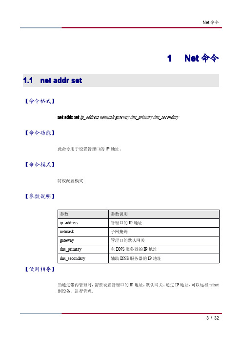
1N et命令1.1net addr set【命令格式】net addr set ip_address netmask gateway dns_primary dns_secondary【命令功能】此命令用于设置管理口的IP地址。
【命令模式】特权配置模式【参数说明】【使用指导】当通过带内管理时,需要设置管理口的IP地址,默认网关。
通过IP地址,可以远程telnet到设备,进行管理。
【配置实例】在示例中,设置了相应的地址和默认网关,DNS服务器的地址。
RG-ACE#net addr setMGT interface ip address[192.168.0.123]:192.168.1.221MGT interface netmask[255.255.255.0]:255.255.255.0MGT interface gateway[192.168.0.3]:192.168.1.1DNS primary[0.0.0.0]:192.168.1.1DNS secondary[0.0.0.0]:Your configuration is:====================================================Gateway:192.168.1.1Primary DNS:192.168.1.1Secondary DNS:0.0.0.0====================================================Port Interface IP Address Netmask Status-----------------------------------------------------------------------1INT0N/A N/A UP2EXT0N/A N/A UP3MGT192.168.1.221255.255.255.0UP4HA N/A N/A UP====================================================Do you really want to apply and save[Y/N]?[N]?Y1.2net addr show【命令格式】net addr show【命令功能】此命令用于显示系统的管理接口参数。
ControlNet网络媒介组件说明书

Components ListControlNet Media SystemThis document contains the ControlNet network media components.For the most current list, see the NetLinx Selection Guide,publication NETS-SG001.Contact your Rockwell Automation representative for information about ordering ControlNet network media components.Nonhazardous LocationsThe table lists components available for nonhazardous environments.You may be able to buy fewer component pieces than shown per order or you may have to purchase all the pieces per order depending upon a unique situation. For more information, contact your distributor or the Rockwell Automation sales office.Cat. ponent DescriptionCoaxial tap kits - See the ControlNet Coax Media Planning and Installation Guide, publication CNET-IN002, for more information.1786-TPR Right-angle T-tap •IP20•1 piece per order 1786-TPS Straight T-tap 1786-TPYR Right-angle Y-tap 1786-TPYS Straight Y-tap Coaxial connectors - See the ControlNet Coax Media Planning and Installation Guide, publication CNET-IN002, for more information.2 ControlNet Media System Components ListCat. ponent DescriptionRG-6 quad-shield coaxial cable -See the ControlNet Coax Media Planning and Installation Guide, publication CNET-IN002, for more information.1786-RG6F/A High-flex•304.8 m (1000 ft)1786-RG6Standard PVC CM-CL2•304.8 m (1000 ft)1786-CTK Coax toolkit Includes:•ControlNet Coax Media Planning andInstallation Guide, publicationCNET-IN002•Cable strip tool•Memory blade holder•Memory blade cartridges•Calibration/flare tool•Crimp tool1788-CNCHKR ControlNet NetChecker Handheld diagnostic tool that analyzesactive ControlNet networks1788-MCHKR NetLinx Media Checker Handheld diagnostic tool that identifiescable failures, measures length, and checkswiring for ControlNet, DeviceNet, DH+/RIO,and Ethernet physical mediaIP67 TNC media -See the ControlNet IP67 Tap and Cable Assembly Kit Installation Instructions, publication 1786-IN017, formore information.Publication AG-PA002E-EN-P - April 2010ControlNet Media System Components List 3Repeater adapter - See the following publications for more information:•ControlNet Fiber Media Planning and Installation Guide, publication CNET-IN001•ControlNet Ex Media Planning and Installation Guide, publication CNET-IN0031786 RPA/B Modular repeater adapter•Supplies power for up to four repeatermodules (1786-RPCD, 1786-RPFS, and1786-RPFM)•Supplies power for up to two repeatermodules (1786-RPFRL, 1786-RPFXL)•One coax BNC connection•RG6 copper coaxUse with these repeater modules:•1786-RPCD•1786 RPFS•1786 RPFM•1786-RPFRL•1786-RPFRXLRepeater modules - See the following publications for more information:•ControlNet Fiber Media Planning and Installation Guide, publication CNET-IN001•ControlNet Ex Media Planning and Installation Guide, publication CNET-IN0031786-RPCD Coaxial repeater•Two coaxial segments per module•Point-to-point and star topologies•RG6 copper coax1786-RPFS Short-distance fiber repeater•Two fiber segments per module•Point-to-point and star topologies •V-pin style connector, use pre-made 1786-FS cable with any of the following catalog numbers:1786-FS101786-FS201786-FS601786-FS1001786-FS2001786-FS300See page4 for more information.1786-RPFM Medium-distance fiber repeater•Two fiber segments per module•Point-to-point and star topologies •ST-style connector, 62.5/125 micron multimode fiber1786-RPFRL/B Long-distance fiber ring repeater•Two fiber segments per module•Point-to-point, star, and ring topologies•Fault relay for runtime diagnostics •ST-style connector, 62.5/125 micron multimode fiber1786-RPFRXL/B Extra-long-distance fiber ring repeater•Two fiber segments per module•Point-to-point, star, and ring topologies•Fault relay for runtime diagnostics •ST-style connector, 62.5/125 micron multimode fiber•ST-style connector, 9/125 micron single mode fiberCat. ponent DescriptionPublication AG-PA002E-EN-P - April 2010Publication AG-PA002E-EN-P - April 20104 ControlNet Media System Components ListShort-distance fiber-optic cable with V-pin connectors - See the ControlNet Fiber Media Planning and Installation Guide, publication CNET-IN001, for more information.1786-FS1010 m (32.8 ft) cable assembly •200 micron cable•Use with the 1786-RPFS repeater1786-FS2020 m (65.6 ft) cable assembly 1786-FS6060 m (196.8 ft) cable assembly 1786-FS100100 m (328.1 ft) cable assembly 1786-FS200200 m (656.2 ft) cable assembly 1786-FS300300 m (948.2 ft) cable assemblyNetwork access cable (laptop computer to ControlNet network) - See the ControlNet Network Access Cable Installation Instructions, publication 1786-TD006, for more information.1786-CP3.05 m (10 ft) cable assemblyControlNet network access cableCat. ponent DescriptionPublication AG-PA002E-EN-P - April 2010ControlNet Media System Components List 5Hazardous LocationsThe table lists components available for hazardous environments.You may be able to buy fewer component pieces than shown per order or you may have to purchase all the pieces per order depending upon a unique situation. For more information, contact your distributor or the Rockwell Automation sales office.Cat. ponentDescriptionIntrinsically safe (FLEX Ex) tap kits - See the ControlNet Ex Media Planning and Installation Guide, publication CNET-IN003, for more information.1797-TPR FLEX Ex right-angle T-tap •IP20•1 piece per order1797-TPS FLEX Ex straight distance T-tap 1797-TPYR FLEX Ex right-angle Y-tap 1797-TPYSFLEX Ex straight Y-tapIntrinsically safe (FLEX Ex) connectors - See the ControlNet Ex Media Planning and Installation Guide, publication CNET-IN003, for more information.See the ControlNet Ex Media Planning and Installation Guide, publication CNET-IN003, for more information.1797-BOOT FLEX Ex boot insulator kit • 1 kit containing 50 pieces 1797-EXMK FLEX Ex cable marking kit • 1 kit containing 100 pieces Coaxial barrier - See the ControlNet Ex Media Planning and Installation Guide, publication CNET-IN003, for more information.1797-BCNRCoaxial barrierIsolates a ControlNet segment from a hazardous to a non-hazardous areaRepeater adapter - See the following publications for more information:•ControlNet Fiber Media Planning and Installation Guide, publication CNET-IN001•ControlNet Ex Media Planning and Installation Guide, publication CNET-IN0031797-RPAIntrinsically safe modular repeater adapter •Supplies power for up to two repeater modules (1797-RPFM)•One coax BNC connectionRG6 copper coax•Use with the 1797-RPFM repeater6 ControlNet Media System Components ListRepeater module - See the following publications for more information:•ControlNet Fiber Media Planning and Installation Guide, publication CNET-IN001•ControlNet Ex Media Planning and Installation Guide, publication CNET-IN0031797-RPFM Intrinsically safe medium-distance repeater•Two fiber segments per module•Point-to-point and star topologies •ST-style connector, 62.5/125 micron multimode fiber•Connect the 1797-RPFM repeater module (in an intrinsically safe area) to the 1786-RPFM repeater module (in a non-intrinsically safe area) using fiberCat. ponent DescriptionPublication AG-PA002E-EN-P - April 2010ControlNet Media System Components List 7 Notes:Publication AG-PA002E-EN-P - April 2010Rockwell Automation SupportRockwell Automation provides technical information on the Web to assist you in using its products. At/support/, you can find technical manuals, a knowledge base of FAQs, technical andapplication notes, sample code and links to software service packs, and a MySupport feature that you can customize to make the best use of these tools.For an additional level of technical phone support for installation, configuration, and troubleshooting, we offer TechConnect support programs. For more information, contact your local distributor or Rockwell Automation representative, or visit /support/.Installation AssistanceIf you experience an anomoly within the first 24 hours of installation, review the information that is contained in this manual.You can contact Customer Support for initial help in getting your product up and running.New Product Satisfaction ReturnRockwell Automation tests all of its products to ensure that they are fully operational when shipped from the manufacturing facility. However, if your product is not functioning and needs to be returned, follow these procedures.Documentation FeedbackYour comments will help us serve your documentation needs better. If you have any suggestions on how to improve this document, complete this form, publication RA-DU002, available at /literature/.Allen-Bradley, Rockwell Automation, Rockwell Software, NetLinx, and TechConnect are trademarks of Rockwell Automation, Inc.Trademarks not belonging to Rockwell Automation are property of their respective companies.United States or Canada1.440.646.3434Outside United States or Canada Use the Worldwide Locator at /support/americas/phone_en.html , or contact your local Rockwell Automation representative.United States Contact your distributor. You must provide a Customer Support case number (call the phone number above to obtain one) to your distributor to complete the return process.Outside United StatesPlease contact your local Rockwell Automation representative for the return procedure.。
合勤交换机使用手册

合勤科技交换机使用手册速查版本 1.0目录1. 硬件连接、常规设置与维护 (4)1.1 硬件安装 (4)1.2 硬件介绍 (5)1.3 常规设置 (6)2. 常规维护 (11)3. 高级设定 (13)3.1 VLAN设定 (13)3.2 STP(生成树协议)设置 (24)3.3 Access Control List (访问控制列表) (28)3.4 ES-3124_ACL功能完成IP与MAC的绑定 (32)3.5 ES-3124_Link Aggregation设置 (36)3.6 IGMP Snooping(组播侦听) (38)3.7 Static MAC Forwarding(静态MAC地址转发) (39)3.8 Filtering (过滤器) (39)3.9 Broadcast Storm Control (广播风暴控制) (39)3.10 Mirroring (端口镜像) (40)3.11 DHCP Relay (41)1. 硬件连接、常规设置与维护本章节介绍硬件连接方法,常规设置和基本维护方法,能够帮助您快速安全的将交换机接入网络。
1.1 硬件安装1.1.1 独立式安装:您可以将随机配备的绝缘脚垫安装到交换机底部,并将交换机置放到安全、干燥、清洁的环境中。
图-11.1.2 机架式安装(1)将随机配备的安装部件牢固的固定在交换机两侧。
如下图所示:图-2(2)利用安装部件将交换机牢固的安装在您的机架上。
如下图所示:注释: 合勤科技交换机系列,ES-2024A/ ES-3124/ ES-3148/ GS-2024/ ES-1528/ ES-1552/ GS-1524/ GS-1548都是标准的19英寸长度设计。
图-31.2 硬件介绍合勤交换机前面板的设计大体相似, 左侧是10/100/1000Mbps以太网接口,或者SFP光口。
右侧通常是上联端口,1000Mpbs的以太网接口或者SFP光口,或者是以太网和SFP双重属性端口。
合勤交换机使用手册

合勤科技交换机使用手册速查版本 1.0目录1. 硬件连接、常规设置与维护 (3)1.1 硬件安装 (3)1.2 硬件介绍 (3)1.3 常规设置 (5)2. 常规维护 (10)3. 高级设定 (12)3.1 VLAN设定 (12)3.2 STP(生成树协议)设置 (22)3.3 Access Control List (访问控制列表) (26)3.4 ES-3124_ACL功能完成IP与MAC的绑定 (30)3.5 ES-3124_Link Aggregation设置 (34)3.6 IGMP Snooping(组播侦听) (36)3.7 Static MAC Forwarding(静态MAC地址转发) (37)3.8 Filtering (过滤器) (37)3.9 Broadcast Storm Control (广播风暴控制) (37)3.10 Mirroring (端口镜像) (38)3.11 DHCP Relay (39)1. 硬件连接、常规设置与维护本章节介绍硬件连接方法,常规设置和基本维护方法,能够帮助您快速安全的将交换机接入网络。
1.1 硬件安装1.1.1 独立式安装:您可以将随机配备的绝缘脚垫安装到交换机底部,并将交换机置放到安全、干燥、清洁的环境中。
图-11.1.2 机架式安装(1)将随机配备的安装部件牢固的固定在交换机两侧。
如下图所示:图-2(2)利用安装部件将交换机牢固的安装在您的机架上。
如下图所示:注释: 合勤科技交换机系列,ES-2024A/ ES-3124/ ES-3148/ GS-2024/ ES-1528/ ES-1552/ GS-1524/ GS-1548都是标准的19英寸长度设计。
图-31.2 硬件介绍合勤交换机前面板的设计大体相似, 左侧是10/100/1000Mbps以太网接口,或者SFP光口。
右侧通常是上联端口,1000Mpbs的以太网接口或者SFP光口,或者是以太网和SFP双重属性端口。
通用路由平台 VRP 说明书 QoS 分册
目录第1章 QoS简介.....................................................................................................................1-11.1 简介....................................................................................................................................1-11.2 传统的分组投递业务..........................................................................................................1-11.3 新业务引发的新需求..........................................................................................................1-21.4 拥塞的产生、影响和对策...................................................................................................1-21.4.1 拥塞的产生..............................................................................................................1-21.4.2 拥塞的影响..............................................................................................................1-31.4.3 对策.........................................................................................................................1-31.5 几种主要的流量管理技术...................................................................................................1-4第2章流量监管和流量整形配置............................................................................................2-12.1 简介....................................................................................................................................2-12.1.1 流量监管..................................................................................................................2-12.1.2 流量整形..................................................................................................................2-32.1.3 接口限速..................................................................................................................2-52.2 配置流量监管.....................................................................................................................2-62.2.1 建立配置任务...........................................................................................................2-62.2.2 配置流量监管列表....................................................................................................2-72.2.3 配置流量监管策略....................................................................................................2-72.2.4 检查配置结果...........................................................................................................2-72.3 配置流量整形.....................................................................................................................2-82.3.1 建立配置任务...........................................................................................................2-82.3.2 配置流量整形...........................................................................................................2-82.3.3 检查配置结果...........................................................................................................2-92.4 配置接口限速.....................................................................................................................2-92.4.1 建立配置任务...........................................................................................................2-92.4.2 配置接口限速.........................................................................................................2-102.4.3 检查配置结果.........................................................................................................2-102.5 配置举例...........................................................................................................................2-102.5.1 流量监管配置示例..................................................................................................2-102.5.2 流量整形配置示例..................................................................................................2-12第3章拥塞管理配置..............................................................................................................3-13.1 简介....................................................................................................................................3-13.1.1 拥塞管理策略...........................................................................................................3-13.1.2 拥塞管理技术的对比................................................................................................3-53.2 配置先进先出队列..............................................................................................................3-63.2.1 建立配置任务...........................................................................................................3-63.2.2 配置FIFO队列的长度.............................................................................................3-73.3 配置优先队列.....................................................................................................................3-73.3.1 建立配置任务...........................................................................................................3-73.3.2 配置优先列表...........................................................................................................3-83.3.3 配置缺省队列...........................................................................................................3-93.3.4 配置队列长度...........................................................................................................3-93.3.5 在接口上应用优先列表组.........................................................................................3-93.3.6 检查配置结果.........................................................................................................3-103.4 配置定制队列...................................................................................................................3-103.4.1 建立配置任务.........................................................................................................3-103.4.2 配置定制列表.........................................................................................................3-113.4.3 配置缺省队列.........................................................................................................3-113.4.4 配置队列长度.........................................................................................................3-123.4.5 配置各队列每次轮询发送的字节数........................................................................3-123.4.6 在接口上应用定制列表..........................................................................................3-123.4.7 检查配置结果.........................................................................................................3-133.5 配置加权公平队列............................................................................................................3-133.5.1 建立配置任务.........................................................................................................3-133.5.2 配置加权公平队列..................................................................................................3-143.5.3 检查配置结果.........................................................................................................3-143.6 配置RTP队列..................................................................................................................3-143.6.1 建立配置任务.........................................................................................................3-143.6.2 在接口上应用RTP队列.........................................................................................3-153.6.3 配置最大预留带宽..................................................................................................3-163.6.4 检查配置结果.........................................................................................................3-163.7 优先队列配置举例............................................................................................................3-16第4章拥塞避免配置..............................................................................................................4-14.1 简介....................................................................................................................................4-14.2 配置WRED........................................................................................................................4-34.2.1 建立配置任务...........................................................................................................4-34.2.2 启用WRED............................................................................................................4-44.2.3 配置WRED计算平均队长的指数............................................................................4-44.2.4 配置WRED各优先级参数.......................................................................................4-44.2.5 检查配置结果...........................................................................................................4-5第5章基于类的QoS配置.....................................................................................................5-15.1 简介....................................................................................................................................5-15.1.1 流分类......................................................................................................................5-25.1.2 标记.........................................................................................................................5-25.1.3 DSCP......................................................................................................................5-35.1.4 标准的PHB.............................................................................................................5-35.1.5 基于类的队列CBQ(Class Based Queue)..........................................................5-4 5.2 配置流分类.........................................................................................................................5-45.2.1 建立配置任务...........................................................................................................5-45.2.2 在类视图中定义匹配类的规则.................................................................................5-55.2.3 检查配置结果...........................................................................................................5-6 5.3 配置基于类的标记动作.......................................................................................................5-75.3.1 建立配置任务...........................................................................................................5-75.3.2 配置标记报文的DSCP值........................................................................................5-85.3.3 配置标记报文的IP优先级值...................................................................................5-85.3.4 配置标记FR报文的DE标志位的值........................................................................5-85.3.5 配置标记ATM信元的CLP标志位的值...................................................................5-85.3.6 配置标记MPLS EXP域的值...................................................................................5-95.3.7 配置标记VLAN优先级8021P的值.........................................................................5-9 5.4 配置基于类的流量监管和流量整形动作.............................................................................5-95.4.1 建立配置任务...........................................................................................................5-95.4.2 配置基于类的流量监管动作...................................................................................5-105.4.3 配置基于类的流量整形动作...................................................................................5-105.4.4 检查配置结果.........................................................................................................5-11 5.5 配置基于类的流量限速动作..............................................................................................5-115.5.1 建立配置任务.........................................................................................................5-115.5.2 配置基于类的流量限速动作...................................................................................5-125.5.3 检查配置结果.........................................................................................................5-12 5.6 配置CBQ动作.................................................................................................................5-125.6.1 建立配置任务.........................................................................................................5-125.6.2 配置AF..................................................................................................................5-135.6.3 配置WFQ..............................................................................................................5-135.6.4 配置最大队列长度..................................................................................................5-145.6.5 配置EF.................................................................................................................5-145.6.6 检查配置结果.........................................................................................................5-14 5.7 配置基于类的WRED动作...............................................................................................5-155.7.1 建立配置任务.........................................................................................................5-155.7.2 配置基于类的WRED丢弃方式.............................................................................5-155.7.3 配置基于类的WRED的丢弃参数.........................................................................5-165.7.4 检查配置结果.........................................................................................................5-16 5.8 配置流量策略...................................................................................................................5-175.8.1 建立配置任务.........................................................................................................5-175.8.2 定义策略并进入策略视图.......................................................................................5-175.8.3 为流分类指定流动作..............................................................................................5-185.8.4 检查配置结果.........................................................................................................5-185.9 配置策略嵌套动作............................................................................................................5-185.9.1 建立配置任务.........................................................................................................5-185.9.2 配置策略嵌套动作.................................................................................................5-195.9.3 检查配置结果.........................................................................................................5-205.10 应用策略.........................................................................................................................5-205.10.1 建立配置任务.......................................................................................................5-205.10.2 应用策略..............................................................................................................5-215.10.3 检查配置结果.......................................................................................................5-215.11 调试CBQ.......................................................................................................................5-215.12 配置举例.........................................................................................................................5-225.12.1 基于类的队列配置举例........................................................................................5-225.12.2 策略嵌套配置举例...............................................................................................5-26第6章 QPPB配置..................................................................................................................6-16.1 简介....................................................................................................................................6-16.2 配置QPPB.........................................................................................................................6-26.2.1 建立配置任务...........................................................................................................6-26.2.2 配置路由策略...........................................................................................................6-36.2.3 应用路由策略...........................................................................................................6-46.2.4 定义类及类的匹配规则............................................................................................6-46.2.5 配置基于类的动作....................................................................................................6-46.2.6 定义流量策略...........................................................................................................6-46.2.7 在接口下应用流量策略............................................................................................6-46.2.8 在接口下应用QPPB................................................................................................6-56.2.9 检查配置结果...........................................................................................................6-56.3 QPPB配置举例..................................................................................................................6-56.4 故障排除...........................................................................................................................6-11第7章链路效率机制配置.......................................................................................................7-17.1 简介....................................................................................................................................7-17.1.1 IP报文头压缩..........................................................................................................7-17.1.2 链路分片与交叉.......................................................................................................7-27.2 配置IP报文头压缩.............................................................................................................7-37.2.1 建立配置任务...........................................................................................................7-37.2.2 启动IP头压缩........................................................................................................7-47.2.3 配置TCP头压缩的最大连接数................................................................................7-47.2.4 配置RTP头压缩的最大连接数................................................................................7-57.2.5 检查配置结果...........................................................................................................7-57.3 配置链路分片和交叉..........................................................................................................7-57.3.1 建立配置任务...........................................................................................................7-57.3.2 使能LFI..................................................................................................................7-67.3.3 配置LFI分片的最大时延........................................................................................7-67.3.4 配置MP绑定带宽....................................................................................................7-67.3.5 启动VT接口动态QoS的限速功能.........................................................................7-77.4 维护....................................................................................................................................7-77.4.1 调试IP头压缩.........................................................................................................7-77.4.2 清空压缩运行信息....................................................................................................7-8第8章帧中继QoS配置.........................................................................................................8-18.1 简介....................................................................................................................................8-18.1.1 帧中继class............................................................................................................8-28.1.2 实现的帧中继QoS...................................................................................................8-28.2 配置帧中继流量整形..........................................................................................................8-58.2.1 建立配置任务...........................................................................................................8-58.2.2 配置帧中继流量整形参数.........................................................................................8-68.2.3 将整形参数应用到接口............................................................................................8-78.2.4 使能帧中继流量整形................................................................................................8-78.3 配置帧中继流量监管..........................................................................................................8-88.3.1 建立配置任务...........................................................................................................8-88.3.2 配置帧中继流量监管参数.........................................................................................8-98.3.3 将流量监管参数应用到接口.....................................................................................8-98.3.4 使能帧中继流量监管................................................................................................8-98.4 配置帧中继接口的拥塞管理..............................................................................................8-108.4.1 建立配置任务.........................................................................................................8-108.4.2 配置帧中继接口的拥塞管理策略............................................................................8-108.5 配置帧中继虚电路的拥塞管理..........................................................................................8-118.5.1 建立配置任务.........................................................................................................8-118.5.2 配置帧中继虚电路的拥塞管理策略........................................................................8-128.5.3 配置虚电路的DE规则...........................................................................................8-128.5.4 将拥塞策略应用到虚电路.......................................................................................8-138.6 配置帧中继通用队列........................................................................................................8-138.6.1 建立配置任务.........................................................................................................8-138.6.2 配置帧中继通用队列..............................................................................................8-148.6.3 将通用队列应用到帧中继接口...............................................................................8-158.6.4 将通用队列应用到帧中继虚电路............................................................................8-158.6.5 检查配置结果.........................................................................................................8-158.7 配置帧中继PVC PQ队列................................................................................................8-168.7.1 建立配置任务.........................................................................................................8-168.7.2 配置帧中继接口的PVC PQ队列...........................................................................8-168.7.3 配置帧中继虚电路PVC PQ队列等级....................................................................8-178.8 配置帧中继分片................................................................................................................8-188.8.1 建立配置任务.........................................................................................................8-188.8.2 配置帧中继分片.....................................................................................................8-198.8.3 将帧中继分片应用到虚电路...................................................................................8-198.8.4 检查配置结果.........................................................................................................8-198.9 调试帧中继QoS...............................................................................................................8-208.10 配置举例.........................................................................................................................8-208.10.1 帧中继流量整形配置举例.....................................................................................8-208.10.2 帧中继分片配置举例............................................................................................8-22第9章 ATM QoS配置............................................................................................................9-19.1 简介....................................................................................................................................9-19.2 配置ATM PVC的拥塞管理................................................................................................9-29.2.1 建立配置任务...........................................................................................................9-29.2.2 配置ATM PVC的FIFO队列...................................................................................9-39.2.3 配置ATM PVC的CQ队列.....................................................................................9-49.2.4 配置ATM PVC的PQ队列......................................................................................9-49.2.5 配置ATM PVC的WFQ队列..................................................................................9-49.2.6 应用CBQ................................................................................................................9-49.2.7 配置ATM PVC的RTPQ队列.................................................................................9-59.2.8 配置ATM PVC的预留带宽.....................................................................................9-59.3 配置ATM PVC的拥塞避免................................................................................................9-59.3.1 建立配置任务...........................................................................................................9-59.3.2 配置ATM PVC的拥塞避免.....................................................................................9-69.4 配置ATM接口的流量监管.................................................................................................9-79.4.1 建立配置任务...........................................................................................................9-79.4.2 配置ATM接口的流量监管.......................................................................................9-79.5 配置ATM接口基于类的策略..............................................................................................9-89.5.1 建立配置任务...........................................................................................................9-89.5.2 配置ATM接口基于类的策略...................................................................................9-99.6 配置PVC业务映射............................................................................................................9-99.6.1 建立配置任务...........................................................................................................9-99.6.2 配置PVC-Group内PVC的IP优先级..................................................................9-109.6.3 为PVC-Group内创建的PVC配置流量参数.........................................................9-109.7 Multilink PPPoA QoS配置...............................................................................................9-119.7.1 建立配置任务.........................................................................................................9-119.7.2 创建Multilink PPPoA虚拟接口模板......................................................................9-129.7.3 创建PPPoA虚拟接口模板并绑定到Multilink PPPoA...........................................9-129.7.4 配置PPPoA应用...................................................................................................9-129.7.5 在Multilink PPPoA虚拟接口模板上应用QoS策略...............................................9-129.7.6 重启PVC...............................................................................................................9-139.8 配置举例...........................................................................................................................9-139.8.1 ATM PVC上的CBQ配置举例..............................................................................9-13。
RG-NBR路由器命令参考(基础配置命令参考手册)

RGOS™命令参考手册基础配置目录第一章用户界面命令 (1)1.1 基本用户界面相关命令 (1)1.1.1 configure terminal (1)1.1.2 disable (2)1.1.3 enable (2)1.1.4 end (2)1.1.5 exit (3)1.1.6 help (4)1.1.7 interface (5)1.1.8 line (5)1.1.9 router-map (5)1.1.10 setup (5)1.1.11 show histroy (7)第二章系统管理命令 (8)2.1 基本系统管理相关命令 (8)2.1.1 calendar set (8)2.1.2 clock set (8)2.1.3 copy (9)2.1.4 hostname (10)2.1.5 show clock (10)2.1.6 show running-config (11)2.1.7 show startup-config (11)2.1.8 reload (11)2.1.9 write (12)2.2 文件系统操作命令 (13)2.2.1 dir (13)2.2.2 delete (14)2.2.3 rename (14)2.2.4 squeeze (15)2.2.5 format (16)第三章升级与维护相关命令 (18)3.1 HTTP升级与维护相关命令 (18)3.1.1 http cancel (18)3.1.2 http check-version (20)3.1.3 http update [upd|route-db|web]+ (21)3.1.4 http update mode (23)3.1.5 http update server (24)3.1.6 http update time daily (25)3.2 TFTP升级和维护相关命令 (25)3.2.1 copy tftp flash (25)3.2.2 copy tftp update (26)3.2.3 ROM模式下升级 (27)第四章SNTP配置命令 (29)4.1 SNTP配置相关命令 (29)4.1.1 sntp enable (29)4.1.2 sntp interval (29)4.1.3 sntp server (30)4.1.4 show sntp (31)第五章SNMP配置命令 (32)5.1 SNMP配置相关命令 (32)5.1.1 no snmp-server (32)5.1.2 show snmp (33)5.1.3 snmp-server chassis-id (33)5.1.4 snmp-server community (34)5.1.5 snmp-server contact (35)5.1.6 snmp-server enable traps (35)5.1.7 snmp-server host (36)5.1.8 snmp-server location (37)5.1.9 snmp-server packetsize (37)5.1.10 snmp-server queue-length (38)5.1.11 snmp-server system-shutdown (39)5.1.12 snmp-server trap-source (39)5.1.13 snmp-server trap-timeout (40)第六章调试工具命令 (41)6.1 调试工具相关命令 (41)6.1.1 debug (41)6.1.2 ping (43)6.1.3 show (44)6.1.4 service tcp-keepalives-in (44)6.1.5 service tcp-keepalives-out (45)第七章系统日志命令 (47)7.1 系统日志相关命令 (47)7.1.1 logging on (47)7.1.2 terminal monitor (48)7.1.3 logging buffered (48)7.1.4 logging (50)7.1.5 service sequence-numbers (50)7.1.6 service timestamps (51)7.1.7 logging console (52)7.1.8 logging monitor (53)7.1.9 logging trap (54)7.1.10 logging language (54)7.1.11 logging source-interface (55)7.1.12 show logging (56)7.1.13 clear logging (58)第一章 用户界面命令1.1 基本用户界面相关命令用户界面即为用户命令行接口(CLI)包括以下相关命令:z configure terminalz disablez enablez endz exitz helpz historyz interfacez linez router-mapz setupz show histroy1.1.1 configure terminal要从特权用户模式进入全局配置模式,请执行特权用户命令configure terminal。
Belden 10 AWG RG-8型高频线缆说明书

-40°C To +75°C 80°C 114.591 Kg/Km 667.230 N 101.600 mm
Applicable Specifications and Agency Compliance (Overall)
Applicable Standards & Environmental Programs
METRIC MEASUREMENT VERSION
7810A Coax - RG-8 Type
Freq. (MHz) Attenuation (dB/100m)
30
2.2967
50
3.05133
150
5.18398
220
6.36514
450
9.28523
900
13.3209
1500
17.4549
1800
Physical Characteristics (Overall)
Conductor AWG:
# Coax AWG Stranding Conductor Material
Dia. (mm)
1
10 Solid
BCCA - Bare Copper Covered Aluminum 2.7432
Insulation Insulation Material:
817
900
575
1500
437
1800
399
2000
375
2500
334
3000
305
3500
282
4500
247
5800
217
6000
213
Max. Operating Voltage - Non-UL: Voltage 300 V RMS
第八部分 组播配置指南

RGOS® ™用户配置指导手册组播配置第一章 配置IP组播路由1.1概述本章描述如何配置IPv4组播路由协议。
如果要了解本章组播路由命令的完整描述,请参考其它有关 "组播路由命令"的章节。
传统的IP传输只允许一台主机向单个主机(单播通信)或者所有主机(广播通信),组播技术则提供第三种选择:允许一台主机向某些主机发送报文。
这些主机被称为组成员。
发送到组成员的报文目的地址是某个D类地址(224.0.0.0~239.255.255.255)。
组播报文的传输类似于UDP,只是一种尽力保证的服务,不提供类似于TCP的可靠传输和差错控制。
构成组播的应用需要发送方和接收方。
发送方无需加入某个组就可以发送组播报文,而接收方必须事先加入某个组才能接收到这个组的报文。
组成员的关系是动态的,主机可以随时加入或者离开某个组,而且组成员的位置和个数没有任何限制。
如果需要,一台主机可以同时为多个组的成员。
因此,组的活动状态和组成员的个数可随着时间而发生变化。
设备通过执行组播路由协议(例如PIM-DM,PIM-SM等)来维护转发组播报文的路由表,通过IGMP协议来学习在直连网段上组成员的状态。
主机通过发送IGMPReport消息来加入特定的IGMP组。
IP组播技术非常适合于“一对多”的多媒体应用。
1.1.1 组播路由实现在设备软件中,组播路由包括如下协议:协议描述IGMP 运行于组播设备和主机之间,跟踪学习组成员的关系。
PIM-DM 密集模式组播路由协议,运行在组播设备之间,通过建立组播路由表来实现组播转发。
PIM-SM 稀疏模式组播路由协议,运行在组播设备之间,通过建立组播路由表来实现组播转发。
DVMRP 距离向量组播路由协议,运行在组播设备之间,通过建立组播路由表来实现组播转下图显示了在IP组播环境中应用到的组播协议的作用位置:图1IP组播环境中应用到的组播协议图1.1.2 IGMP概述要实现IP组播,组播主机、设备必须能支持IGMP操作。
烽火汇聚交换机常用配置
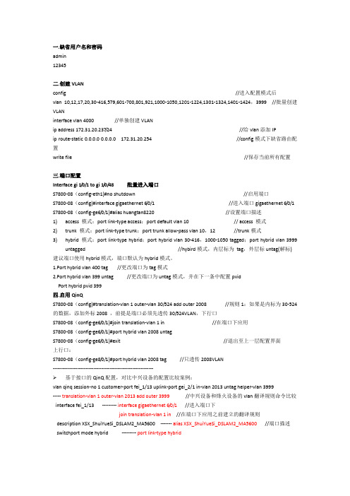
一.缺省用户名和密码admin12345二.创建VLANconfig //进入配置模式后vlan 10,12,17,20,30-416,579,601-700,801,921,1000-1050,1201-1224,1301-1324,1401-1424,3999 //批量创建VLANinterface vlan 4000 //单独创建VLANip address 172.31.20.237/24 //给vlan添加IPip route-static 0.0.0.0 0.0.0.0 172.31.20.254 //config模式下缺省路由配置write file //保存当前所有配置三.端口配置Interface gi 1/0/1 to gi 1/0/48 批量进入端口S7800-08(config-eth1)#no shutdown //启用端口S7800-08(config)#interface gigaethernet 6/0/1 //进入端口gigaethernet 6/0/1 S7800-08(config-ge6/0/1)#alias huangtan8220 //设置端口描述1)access 模式:port link-type access;port default vlan 10 // access 模式2)trunk 模式:port link-type trunk;port trunk allow-pass vlan 10,12 //trunk模式3)hybrid 模式:port link-type hybrid;port hybrid vlan 30-416,1000-1050 tagged;port hybrid vlan 3999untagged //hybird模式,内层标为tag,外层标untag(解标) 建议端口使用hybrid模式,端口默认为hybrid模式。
1.Port hybrid vlan 400 tag //更改端口为tag模式2.Port hybrid vlan 399 untag //更改端口为untag模式,并在下一条中配置pvidPort hybrid pvid 399四.启用QinQS7800-08(config)#translation-vlan 1 outer-vlan 30/524 add outer 2008 //规则1:如果是内标为30-524的数据,添加外标2008 ,前提是端口必须先透传30/524VLAN,下行口S7800-08(config-ge6/0/1)#join translation-vlan 1 in //在端口下应用S7800-08(config-ge6/0/1)#port hybrid vlan 2008 untagS7800-08(config-ge6/0/1)#exit //退出至上一层配置界面上行口:S7800-08(config-ge8/0/1)#port hybrid vlan 2008 tag //只透传2008VLAN--------------------------------------------------------------➢基于接口的QinQ配置,对比中兴设备的配置比较案例:vlan qinq session-no 1 customer-port fei_1/13 uplink-port gei_2/1 in-vlan 2013 untag helper-vlan 3999----- translation-vlan 1 outer-vlan 2013 add outer 3999 //中兴设备和烽火设备的vlan翻译规则命令比较interface fei_1/13 --------- interface gigaethernet 6/0/1 //进入端口下join translation-vlan 1 in //在端口下应用之前建立的翻译规则description XSX_ShuiYueSi_DSLAM2_MA5600 ------- alias XSX_ShuiYueSi_DSLAM2_MA5600 //端口描述switchport mode hybrid --------- port link-type hybridswitchport hybrid native vlan 254 -------- port hybrid pvid 254switchport hybrid vlan 2013 tag --------- port hybrid vlan 2013 tagswitchport hybrid vlan 254 untag -------- port hybrid vlan 254 untagswitchport hybrid vlan 3999 untag ---------port hybrid vlan 3999 untagswitchport qinq customer ---------- dot1q tunnel enable上联口中兴设备需要定义uplink,烽火设备无需该配置,将外层标签定义为untag即可。
锐捷无线控制器RG-RAC64说明书

锐捷网络股份有限公司了解更多产品信息,欢迎登陆 ,咨询电话:400-100-0078。
RG-RAC64高性能无线控制器产品简介RG-RAC64高性能无线控制器是锐捷睿易推出的面向下一代高速无线网络的无线控制器产品。
可突破三层网络保持与AP的通信,部署在任何2层或3层网络结构中,无需改动任何网络架构和硬件设备,从而提供无缝的安全无线网络控制。
RG-RAC64起始支持32个无线接入点的管理,通过license 的升级,最大可支持64个AP的管理。
RG-RAC64产品采用增强的安全和集群技术,通过基于身份的组网来提供网络服务。
集群中的多台无线控制器可共享用户数据库,实现无线用户在跨越整个网络不同区域的过程中无缝的漫游,彻底满足移动漫游中的安全性和会话完整性,充分满足Wi-Fi语音通信的数据交互和语音流畅。
产品特性与价值高智能的无线体验■终端智能识别RG-RAC64内置Portal服务器,能根据终端特点,智能识别终端类型,自适应弹出不同大小、页面格局的Portal认证页面。
终端智能识别技术免去了用户多次拖动,调整屏幕的操作,为用户提供更加智能的无线体验,并且全面支持苹果iOS、安卓和windows等主流智能终端操作系统。
■终端公平访问RG-RAC64协同锐捷无线接入点为802.11g、802.11n、802.11ac等不同类型的终端提供相同的访问时间,极大的解决了因终端无线网卡老旧或终端离AP较远而导致用户无线上网延时大、速度慢、AP整机性能低下的问题,有效的提升了低速终端的性能,保证用户无论使用何种类型的终端,都将在相同的位置上获得同样良好的无线上网体验。
■智能负载均衡在高密度无线用户的情况下,RG-RAC64智能实时的根据每个关联的AP上的用户数及数据流量调整分配到不同的AP上提供接入服务,平衡接入负载压力,提高用户的平均带宽和QoS,提高连接的高可用性。
锐捷无线不仅能实现基于用户、流量的智能负载均衡,而且还能实现基于频段的负载均衡。
rgeg系列出口网关硬件安装手册v128锐捷睿易
文档名称RG-RAC64无线控制器硬件安装手册当前版本 1.02文档密级受控发布对象最终用户发布格式PDF光盘文件修订记录日期文档版本号软件版本号修订内容修订人2016-01-25 1.00 11.x 初次发行苏洋2016-04-22 1.01 11.x 修订产品介绍,增加附录 A 苏洋2016-06-30 1.02 11.x 参数修订苏洋1 产品介绍RG-RAC64是锐捷网络推出的面向下一代高速无线网络的无线控制器产品,主要应用于中大型无线局域网,提供强大的WLAN接入控制功能。
可突破三层网络保持与AP的通信,部署在任何2层或3层网络结构中,无需改动任何网络架构和硬件设备,从而提供无缝的安全无线网络控制。
RG-RAC64起始支持32个无线接入点的管理,通过license 的升级,最大可支持64个无线接入点的管理。
1.1 RG-RAC64规格参数产品型号RG-RAC64存储器DDR3 SDRAM:2GB BOOTROM:8MB FLASH :512MBI/O设置4个RJ45电口控制台口:1个USB接口:2个接口标准以太网:10Base-T/100Base-TX/1000Base-TX 配置口(控制台口):RS-232外型尺寸(宽×高×深)(单位:mm)440×43.6×200(不含脚垫)电压100-240V~,50-60Hz功耗小于40W工作温度温度:-10°~45℃工作湿度湿度:5%~95%(无凝结)由于U盘型号众多,不能保证系统支持所有的USB设备。
建议使用正品金斯顿U盘,并且U盘文件系统格式为FAT32。
请在搬运产品及使用过程中避免振动和冲击。
产品外观图1-1 RG-RAC64无线控制器产品前面板图1-2 RG-RAC64无线控制器产品后面板指示灯指示灯说明工作状态PWR 电源正常:绿色常亮电源关闭或故障:不亮SYS 上电初始化:绿色闪烁初始化完成:绿色常亮告警:红色常亮1-4电口link/ACT指示灯千/百/十兆Link:绿色常亮数据收发:绿色闪烁1-4电口speed指示灯千兆:橙色常亮百/十兆:不亮2 安装前的准备2.1 安全注意事项无线控制器承担着无线网络中的重要作用,其正常使用关系到整个无线网络是否能正常运作。
EverFocus EQH5102 Mini Box Camera User's Manual

EverFocus EQH5102 Mini Box Camera manual/everfocus/eqh5102-mini-box-camera-manual.htmlThe EQH5102 is an HDcctv outdoor mini IR ball camera. Based on a progressive scan CMOS sensor, the camera provides 1080p high resolution images and superior video quality compared to traditional CCTV images. This superior resolution not only captures more critical evidentiary information, but the inherent ability for megapixel video also extends the area of coverage, expedites completion of investigations, resolves complaints and reduces both capital and operational costs. collects and classifies the global productinstrunction manuals to help users access anytime andanywhere, helping users make better use of products.EQH5102 1080p Mini Box CameraUser’s Manual** Lens not included.Copyright © EverFocus Electronics Corp,Release Date: July, 2012PrecautionsPlease read this manual first to ensure correct installation and operation. This manual should be retained for future reference. The information in this manual was current when published. The manufacturer reserves the right to revise and improve its products. All specifications are therefore subject to change without notice.1. Do not install the camera near electric or magnetic fields.Install the camera away from TV / radio transmitters, magnets, electric motors, transformers and audio speakers, because the electromagnetic fields generated by these devices may distort the video image or otherwise interfere with camera functions.2. Never disassemble the camera beyond the recommendations in this manual, nor applymaterials to it other than those recommended herein.Improper disassembly or introduction of corrosive materials may result in equipment failure or other damage.3. Try to avoid pointing the camera toward the sun.In some circumstances, direct sunlight may cause permanent damage to the sensor and / or internal circuits. It may also create unbalanced illumination that may be beyond the camera’s ability to compensate.4. Keep the power cable away from water and other liquids. Never touch the power cablewith wet hands.Touching a wet power cable with your hands or touching the power cable with wet hands may result in electric shock.5. Never install the camera in areas exposed to oil, gas or solvents.Oil, gas or solvents may cause equipment failure, electric shock or, in extreme cases, fire. 6. CleaningFor cameras with interchangeable lenses, do not touch the surface of the sensor directly with your hands. Use lens tissue or a cotton tipped applicator and ethanol to clean thesensor and the camera lens. Use a damp soft cloth to remove any dirt from the camera body.Do not use complex solvents, or corrosive or abrasive agents to clean any part of the camera.7. Do not operate the camera beyond the specified temperature, humidity and power sourcelevels. This camera is suitable for indoor operation only.Use the camera at temperatures within0°C ~ 45°C (32°F ~ 113°F) and humidity between 20 ~ 80%; this device is not rated as submersible. The input power source should be 12VDC. The use of a properly fused or “Class 2 L imited Power Source” power supply is highlyrecommended.8. MountingSelect a solid mounting surface that will support the weight of the camera and anyadditional loading from wind, snow, ice or other factors. Securely attach the camera to the mounting surface using screws and anchors that will properly support the camera. Ifnecessary, (e.g. when mounting the camera to a drop ceiling, or unsupported ceiling) use a safety wire to provide additional support for the camera.iiiSafety NoticeFederal Communication Commission Interference StatementThis equipment has been tested and found to comply with the limits for a Class A digital device,pursuant to Part 15 of the FCC Rules. These limits are designed to provide reasonable protectionagainst harmful interference in a residential installation. This equipment generates uses andcan radiate radio frequency energy and, if not installed and used in accordance with theinstructions, may cause harmful interference to radio communications. However, there is noguarantee that interference will not occur in a particular installation. If this equipment doescause harmful interference to radio or television reception, which can be determined by turningthe equipment off and on, the user is encouraged to try to correct the interference by one of thefollowing measures:- Reorient or relocate the receiving antenna.- Increase the separation between the equipment and receiver.- Connect the equipment into an outlet on a circuit different from that to which the receiveris connected.- Consult the dealer or an experienced radio/TV technician for help.FCC Caution: Any changes or modifications not expressly approved by the party responsible forcompliance could void the user's authority to operate this equipment.This device complies with Part 15 of the FCC Rules. Operation is subject to the following twoconditions: (1) This device may not cause harmful interference, and (2) this device must acceptany interference received, including interference that may cause undesired operation.Contents1. INTRODUCTION (1)1.1 P ACKING L IST (1)1.2 F EATURES (1)2. OVERVIEW (2)3. INSTALLATION (2)3.1L ENS I NSTALLATION AND A DJUSTMENT (2)3.2T OP /B OTTOM-M OUNT (3)4. BASIC CONNECTION (3)5. CONFIGURATION IN THE OSD MENU (3)5.1.1EXPOSURE (4)6.SPECIFICATIONS (10)7.APPENDIX (11)7.1 OSD M ENU S TRUCTURE (11)iii1. IntroductionThe EQH5102 is an HDcctv indoor mini box camera. Based on a progressive scan CMOS sensor for HD 1080p resolution 100% digital images, it delivers vastly superior video quality compared to traditional CCTV images. This superior resolution not only captures more critical evidentiary information, but the inherent ability for megapixel video also extends the area of coverage, expedites completion of investigations, resolves complaints and reduces both capital and operational costs.No major upgrade to the IT network is required to deploy this powerful technology; HDcctv cameras communicate at digital speeds up to 1.5 Gb/s over existing or new coaxial cable (RG59 or other types for longer distances), using industry standard BNC connectors.The EQH5102 allows flexible choices of megapixel manual & DC iris control lenses with C / CS mount for outstanding coverage in a wide range of demanding surveillance environments while delivering stunning HD image quality.1.1 Packing List∙Camera body x 1 ∙Lens Cover x1∙Power Pigtail Cable x 1 ∙C-mount lens adapter x 1∙User Manual x 11.2 Features∙Real time HDcctv 1080p HD video over coax for superlative image detail∙1/3” 2.1 megapixel Color Progressive CMOS sensor∙CS/C mount, manual and DC iris control for flexible choice of HD Megapixel lenses∙Provides 3D DNR/ DSS to improve image clarity, particularly in low light scenes∙Electronic Lens Shading Compensation to offset diminished light transmission through lens periphery for uniform image illumination∙CTB [Contrast Boost] to deliver properly exposed images despite bright light sources, deep shadows and/or unbalanced lighting in the same scene∙Supports Digital Zoom/ BLC [Back Light Compensation]/ HSMASK [Highlight Suppression Mask]/ Privacy Zones (up to 32)∙DPC [Defect Pixel Correction] Dead pixel compensation for increased clarity and extended service life∙SD TV Out for aim and focus using a standard hand held test monitor12. OverviewNo.Name Descriptions 1HDcctv Output Connects to a HD device using a 75 Ohm BNC-type coaxial cable. 2OSD Menu Joystick Use the joystick to configure the settings in the OSD menu. 3Screwless Terminal Strip Connects to a 12VDC power, RS-485 and MD (Motion Detect) source. 4Power LED Glows red then power is present. 5Grounding Stud Ensuring a good grounding when used. 6Test-Out Connects to a SD CVBS monitor for setting image aim and focus.3. Installation3.1 Lens Installation and AdjustmentYou can install either a CS-mount or a C-mount lens into the camera. It is recommended to use a lens with aperture ratio of F/1.2 or lower. Please refer to the following reference steps. CS-Mount Lens:1.Remove the cover cap from the camera body. 2.Install the lens into the camera body. 3.Adjust the lens using the Focus / Zoom Screws.If you are using a DC Auto Iris lens:1.Remove the cover cap from the camera body.2.Install the lens into the camera body.3.Connect the DC cable to the DC Auto Iris Lens Connector.4.Lock the Focus Screw.C-Mount Lens:1.Remove the cover cap from the camera body.2.Install the lens into the camera body using the supplied C-mount lens adapter.3.Adjust the lens using the Focus / Zoom Screws.3.2 Top / Bottom-MountYou can use a mounting bracket and screw it on the top of the camera body to suspend the camera, or on the bottom of the camera body to support the camera.4. Basic Connection1.Connect the camera to an HD device, such as an HDcctv DVR, to display the image.2.Connect the camera to a 12VDC power source using the supplied Power Cable. You canoptionally use the supplied Power Pigtail Cable or a power adapter to connect the Power Cable to the power source. The power LED will be lit in red.3.Connect the camera to a CVBS portable monitor for setting image aim and focus beforemounting the camera.5. Configuration in the OSD MenuYou can use the Joystick on the rear panel of the camera to configure camera settings in the OSD menu. For details on the OSD menu structure, see OSD Menu Structure in Appendix.5.1 OSD MenuPress the Enter / Confirm button on the Joystick. The Setup Menu in the OSD appears.5.1.1 EXPOSUREPress the Enter / Confirm button to enter the submenu.BRIGHTNESSUse the ③ and ④ buttons to increase or decrease the screen brightness from 0 to 20.MODEIndoorSelect this mode when the color temperature of the video image is similar to that found in indoor environments (around 5100 to 5300°K).OutdoorSelect this mode when the color temperature of the video image is similar to that found in outdoor environments (around 3,000°K to 3,200°K)LENSYou can select the type of the lens. Two types are available: Manual and DC. By default, the DC type lens is selected.ShutterUse the ③ and ④ buttons to adjust the shutter speed. The options include: 1/25 ~ 1/60000, FLK, and AUTO. Any selection other than AUTO and 1/25 will disable the DSS function.DSS (Digital Slow Shutter)DSS is used to maintain a vivid screen image by automatically boosting low light levels. The value is between x2 ~ X4 and OFF.AGC (Auto Gain Control)The higher the AGC value, the brighter the screen, but the level of noise will also be increased. The options include: 0~10.5.1.2 COLORPress the Enter / Confirm button to enter the submenu.AWB (Auto White Balance)This mode can be used to view areas with a color temperature range. Use the ③ and ④buttons to select the AWB options. The options include: AUTO, AUTO EXTN, PRESET, MANUAL COLOR TEMP, R-GAIN and B-GAIN.∙AUTO – Around 2500 to 9500°K∙AUTO EXTN (Extension) – Around 2300 to 10800°K∙PRESET – Use a pure white background to preset the white balance value.∙MANUAL COLOR TEMP – Use the ③ and ④ buttons to adjust the speed. The options include: LOW, MIDDLE and HIGH∙R-GAIN and B-GAIN –The options include: 0~20.CHROMAUse the ③ and ④ buttons to increase or decrease the CHROMA from 0 to 20.R-OFFSET/B-OFFSETUse the ③ and ④ buttons to increase or decrease the Red and Blue offset from 0 to 20.5.1.3 IMAGEPress the Enter / Confirm button to enter the submenu.SHARPNESSUse the ③ and ④ buttons to increase or decrease the SHARPNESS from 0 to 10.MIRROR/FLIPTurn it on to reverse/ flip the image.DZOOMTurn it on to set up the zoom levelPRIVACYEnter the submenu to set up the privacy masks; up to 31 zones can be created:ON ZONE NO: Use the ③ and ④ buttons to select the zone from 0 to 31.X, Y-POS, SIZ: Enter the submenu to set up the position or size of the privacy mask zone. COLOR: Press to select a color for the selected privacy mask zone.TRANS: Press to select the transparency of mask zone.SHADINGTurn it on to offset diminished light transmission through lens periphery for uniform imageillumination.DAY&NIGHTThe options include MODE, AGC THRS, DELAY. A submenu can be entered if you select MODE.∙MODE – Use the ③ and ④ buttons to select AUTO, COLOR and B&W. Switches to a B&W feed in low light conditions and then switches back to a Color feed in the daytime.∙AGC THRS –Use the ③ and ④ buttons to select the AGC Threshold from 0 to 20.∙DELAY – Set up the delay time in 0,5,10 and 30 seconds for the camera to switch between Day and Night.HLMASKTurn it on to select the level and color of the masking effect.CTB (Contrast Boost)Turn it on to deliver properly exposed images despite bright light sources, deep shadowsand/or unbalanced lighting in the same scene.GAMMAUse the ③ and ④ buttons to increase or decrease the GAMMA from 0.45 to 0.75.5.1.4 BLCPress the Enter / Confirm button to enter the submenu.MODEUse the ③ and ④ buttons to select OFF and BLC.BLC OSD, POS and SIZSelect OFF to disable the BLC function, or select ON to enable the BLC function and for further setup. After selecting an area block, enter the BLC POS / SIZ and X/ Y setup page, a “POSITION”sign displayed on the screen. Use the direction buttons to move the area to the desiredposition. Press the Enter / Confirm button to confirm the position, a “SIZE” sign displayed on the screen. Use the direction buttons to adjust the size for the area.5.1.5 3D-DNRPress the Enter / Confirm button to enter the submenu.Switch to HIGH, MIDDLE, LOW and OFF to enable or disable noise reduction on dynamic recordings.5.1.6 MOTIONPress the Enter / Confirm button to enter the submenu.RESOLUTIONUse the ③ and ④ buttons to increase or decrease the RESOLUTION level from 0 to 4.SENSITIVITYPress to set up the sensitivity for the motion detection function.WINDOW TRANSPress to select the transparency of motion detect zone.WINDOW USE, POS and SIZSelect OFF to disable this function, or select ON to enable and for further setup. After selecting an area block, enter the BLC POS / SIZ and X/ Y setup page, a “POSITION” sign displayed on the screen. Use the direction buttons to move the area to the desired position. Press the Enter / Confirm button to confirm the position, a “SIZE” sign displayed on the screen. Use the direction buttons to adjust the size for the area.5.1.7 SYSTEMPress the Enter / Confirm button to enter the submenu.DEFECT DETPress to select the DPC (Defective Pixel Correction) level of defect detector. Please notice; do not use this function without cover the lens. The camera will automatically correct pixel defects. Misoperation will cause the abnormal image.CAM TITLESwitch to On and then enter the submenu to set up a camera name displayed on the screen.RS-485Use the ③ and ④ buttons to select ID, BAUDRATE, PROTOCOL and ID DISPLAY. The default of protocol is EVF-1 (EverFocus).VersionPress to display the firmware version of the camera.DOUTThere are 4 options including 1080p 30FPS NTSC, 1080p 25FPS PAL, 720p 60FPS NTSC and 720p 50FPS PALLanguageSelect a language for the OSD text. Options include English, French, German, Simplified Chinese, Korean and Japanese.6. SpecificationsCameraPickup Device 1/3” Panasonic 2.1 megapixel Color Progressive CMOS sensor Image Pixels 1920(H) x 1080(V)Resolution Digital:1080p(30/25), 720p(60/50)Sensitivity Color: 0.4 lux, BW: 0.1 lux,Color DSS: 0.1 lux, BW DSS: 0.025 luxVideo Output Digital(HDcctv Output): BT.1120, HDcctv/HD-SDI: BNC connector Analogue(Test Out): NTSC/PAL CVBS(w/o WDR): BNC connectorS/N Ratio More than 50 dB (AGC OFF)Lens DC/ManualAGC 0-20 stepsShutter Speed AUTO/MANUAL(1/25(30)~1/60,000sec)Digital Slow Shutter(DSS) On/Off(x4)Brightness 0-20BLC On/OffContrast Boost(CTB) On/OffDay&Night Auto/Color/B&WAuto White Balance Auto/Auto extn/Preset/ManualDigital Noise Reduction(DNR) Off/Low/Middle/HighMirror On/OffFlip On/OffSharpness 0 - 10 stepsLens Shading Compensation On/OffDigital Zoom 0 - 96 stepsPrivacy Mask 32 Zones, ProgrammableMotion Detection On/Off(Swith Output, Screwless terminal connector)RS - 485 2400~115200> baud, ID 1~255, Protocols: Pelco-D/P, EverFocus EVF-1; Screwless terminal connectorLanguage English /French /German /Chinese /Korean /Japanese /Russian Power Source 12VDC, Screwless terminal connectorPower Comsumption 12VDC: 220mA max.Operating Environment 0°C~45°C/32°F~113°F (20%~80% Humidity)Dimensions(L x W x H) 89 x 46 x 48mm /3.5” x1.8” x1.9”Weight 0.193kg/0.434lbsCertifications FCC / CE7.Appendix7.1OSD Menu StructureEverFocus Electronics Corp.EverFocus Taiwan:12F, No.79, Sec. 1, Shin-Tai Wu Road, Hsi-Chih, Taipei, TaiwanTEL: +886 2 2698 2334FAX: +886 2 2698 2380***********************.tw EverFocus Europe - Germany: Albert-Einstein-Strasse 1, D-46446 Emmerich, GermanyTEL: +49 2822 93940FAX: +49 2822 939495www.everfocus.de*****************EverFocus China - Beijing:Room 609, Technology Trade Building, Shangdi Information Industry Base, Haidian District, Beijing 100085, China TEL: +86 10 6297 3336~39FAX: +86 10 6297 1423***********************.cn EverFocus China - Shenzhen:4F, No. 2, D4 Building, Wan Yelong Industrial Park, Tangtou Road, Shiyan, Baoan, Shenzhen, Guangdong 518101, China TEL: +86 755 2765 1313FAX: +86 755 2765 0337***********************.cnEverFocus USA - California:1801 Highland Avenue, Unit A, Duarte, CA 91010, USATEL: +1 626 844 8888FAX: +1 626 844 8838*******************EverFocus USA - New York:415 Oser Avenue, Unit S, Hauppauge, NY 11788, USA TEL: +1 631 436 5070FAX: +1 631 436 5027*******************EverFocus Japan:5F, Kinshicho City Building, 2-13-4Koto-Bashi,Sumida-Ku, Tokyo, 130-0022, Japan TEL: +81 3 5625 8188FAX: +81 3 5625 8189www.everfocus.co.jp*****************.jp EverFocus Europe - UK:Unit 12, Spitfire Business Park,Hawker Road, Croydon Surrey, CR0 4WD, UK TEL: +44 20 8649 9757 / +44 845 430 9999 FAX: +44 20 8649 9907*********************EverFocus India:Suite 803, Housefin Bhavan, C-21, Bandra KurlaComplex, Bandra (East), Mumbai 400051, IndiaTEL: +91 22 6128 8700FAX: +91 22 6128 8705www.everfocus.in******************N。
2022年职业考证-通信工程师-通信运营商集中采购考试全真模拟易错、难点剖析B卷(带答案)第2期
2022年职业考证-通信工程师-通信运营商集中采购考试全真模拟易错、难点剖析B卷(带答案)一.综合题(共15题)1.案例题在UMTS中重定向(Redirection)信元可包含在RRC Connection Reject或RRC ConnectionRelease消息中,而在E-UTRA中重定向信元只可包含在RRC Connection Release中,请试图说明下原因。
【答案】重定向时,eNB需要知道UE能力。
在RRC Connection Request由于消息大小的限制无法携带UE 能力。
【解析】暂无解析。
2.案例题LTE下行参考信号的作用是什么?【答案】1.下行信道质量测量。
2.下行信道估计,用于UE端的相干检测和解调。
【解析】暂无解析。
3.判断题每个小区中有_____个可用的随机接入前导。
问题1选项A.对B.错【答案】A【解析】暂无解析。
4.案例题3GPP PCC(Policy and Charging Control)架构定义了从终端、核心网、业务平台到无线设备的端到端联动机制,能下发数据业务流的_____规则和_____规则,实现数据业务的差异化和精细化管控。
【答案】策略控制:计费【解析】暂无解析。
5.案例题室分系统中经常使用到的无源器件包括:_____,_____,_____和天线等。
【答案】合路器、功分器、耦合器【解析】暂无解析。
6.案例题简述TD-LTE系统中基于竞争的随机接入流程。
【答案】基于竞争的随机接入是指eNodeB没有为UE分配专用Preamble码,而是由UE随机选择Preamble 码并发起的随机接入。
竞争随机接入过程分4步完成,每一步称为一条消息,在标准中将这4步称为Msg1-Msg4。
1.Msg1:发送Preamble码 2.Msg2:随机接入响应 3.Msg3: 第一次调度传输 4.Msg4:竞争解决【解析】暂无解析。
7.案例题TD-LTE网络规划时,天线方案的基本思路?【答案】室外天线方案(室外2、8天线的技术选择):由于8天线设备在覆盖和网络性能方面具有优势,因此室外以8天线为主;室内天线方案(室内单、双路室分系统的技术选择):具备条件的区域优先使用双路室分系统。
- 1、下载文档前请自行甄别文档内容的完整性,平台不提供额外的编辑、内容补充、找答案等附加服务。
- 2、"仅部分预览"的文档,不可在线预览部分如存在完整性等问题,可反馈申请退款(可完整预览的文档不适用该条件!)。
- 3、如文档侵犯您的权益,请联系客服反馈,我们会尽快为您处理(人工客服工作时间:9:00-18:30)。
RG Coaxial Cable ListO.D.Cable TypeImped. (Ω)Max Oper. Volts Inches mm Comments:RG-5B/U 50 3000 0.3288.3312For replacement only, use RG-212/URG-6A/U 75 2700 0.3328.4328NoneRG-8A/U 52 5000 0.40510.287For replacement only, use RG-213/U RG-9B/U 50 5000 0.42 10.668For replacement only, use RG-214/U RG-10A/U 52 5000 0.47512.065For replacement only, use RG-215/URG-11A/U 75 5000 0.40510.287None RG-12A/U 75 5000 0.47512.065NoneRG-13A/U 74 5000 0.42 10.668For replacement only, use RG-216/U RG-14A/U 52 7000 0.54513.843For replacement only, use RG-217/URG-15/U 76 5000 0.54513.843None RG-16/U 52 6000 0.63 16.002NoneRG-18A/U 52 11000 0.94524.003For replacement only, use RG-219/U RG-19A/U 52 14000 1.12 28.448For replacement only, use RG-220/U RG-20A/U 52 14000 1.19530.353For replacement only, use RG-221/U RG-21A/U 53 2700 0.3328.4328For replacement only, use RG-222/U RG-22B/U 95 1000 0.42 10.668Balanced cable twisted conductorsRG-23A/U 125 3000 0.94524.003Dual coaxial cable RG-24A/U 125 3000 1.03426.2636Dual coaxial cableRG-25A/U 48 8000 0.50512.827Pulse cable RG-26A/U 48 8000 0.65 16.51 Pulse cableRG-27A/U 48 15000 0.65 16.51 High voltage pulse cable RG-28B/U 48 15000 0.75 19.05 High voltage pulse cableRG-33/U 51 6000 0.47 11.938None RG-34B/U 75 6500 0.63 16.002None RG-35B/U 75 10000 0.94524.003None RG-36/U 69 13000 1.18 29.972None RG-41/U 67.5 3000 0.42510.795None RG-54A/U 58 3000 0.25 6.35 None RG-55B/U 53 1900 0.2065.2324NoneRG-56/U 0.53513.589Special twisted pulse cableRG-57A/U 95 3000 0.62515.875Twin conductor RG-58C/U5019000.195 4.953General purposeRG-59B/U7523000.242 6.1468General purposeRG-60/U500.42510.795None RG-62A/U930.249 6.3246NoneRG-62B/U937500.242 6.1468None RG-63B/U12510000.40510.287Low capacitance RG-64/U480.49512.573Pulse RG-65A/U95010000.40510.287High impedance delay line, video cable RG-71B/U937500.25 6.35None RG-72/U1500.6316.002None RG-73/U250.275 6.985None RG-74A/U5270000.61515.621For replacement only, use RG-224/U RG-77A/U4880000.4511.43Pulse cable RG-78A/U4880000.4210.668Same as RG-74A/U except single braid RG-79B/U12510000.47512.065RG-63B/U with armor RG-81/U5030000.3759.525Semi-Rigid high temperature cable RG-82/U5050000.7519.05Same as RG-81/U RG-83/U3520000.40510.287None RG-84A/U7510000125.4RG-35B/U with lead sheath, not armor RG-85A/U7510000 1.56539.751RG-84A/U with special armor RG-86/U2000.6516.51Twin lead RG-87A/U5050000.42510.795For replacement only. New, use RG-225/U RG-88/U5080000.51513.081Pulse RG-88A/U5080000.51513.081None RG-88B/U50100000.56514.351None RG-89/U12510000.63216.0528Low capacitance RG-90/U5030000.42510.795Carrier Frequency Communication RG-93/U50100000.7118.034Replaced with RG-117/U RG-94/U5070000.44511.303For replacement only. New, use RG-226/U RG-100/U3520000.242 6.1468None RG-108A/U7810000.235 5.969Shielded twisted pair RG-111A/U9510000.4912.446none RG-114A/U18510000.40510.287Special low capacitance RG-115/U5040000.3759.525NoneRG-115A/U5040000.41510.541None RG-116/U5050000.47512.065For replacement only. New, use RG-227/U RG-117A/U5070000.7318.542Same as RG-117/U. New, use RG-211A/U RG-118A/U5070000.7819.812Same as RG-118/U. New, use RG-228A/U RG-119/U5060000.46511.811High temperature cable RG-120/U5060000.52513.335Same as RG-119/U, with armor RG-122/U5019000.16 4.064Same as RG-58/U except smaller in size RG-124/U7323000.24 6.096Replaced by RG-140/U RG-125/U15020000.615.24Special low capacitance RG-126/U5030000.287.112High attenuation same as RG-301/U RG-130/U9580000.62515.875Same as RG-57A/U except inner conductor RG-131/U9580000.7118.034Same as RG-130/U except for armor RG-133A/U9540000.40510.287NATO type NWR7 RG-140/U7520000.233 5.9182High temperature, similar to RG-59A/U RG-141A/U5019000.19 4.826High temperature, similar to RG-58C/U RG-142A/U5019000.206 5.2324High temperature, similar to RG-55A/U RG-142B/U500.195 4.953Same as above RG-143A/U5030000.3258.255High temperature, similar to RG-58/U RG-144/U7550000.4110.414High temperature, similar to RG-11/U RG-147/U5214000 1.93749.1998RG-19/U with armor RG-148/U7240000.820.32RG-8/U with spiral armor RG-149/U5250000.40510.287Low noise RG-150/U7550000.47512.065Same as RG-149/U except armored RG-156/U50100000.5413.716Taped innerlayers 1 type K&1 type A-1R RG-157/U50150000.72518.415Betw 2n braid of outer conductor & braided RG-158/U25150000.72518.415Tinned copper shield pulse cable RG-159/U5023000.195 4.953Replaced by RG-142/U RG-160A/U1253000 1.05526.797Same as RG-160/U except copper braid RG-164/U75100000.8722.098Same as RG-35B/U except armored RG-165/U5050000.4110.414None RG-166/U5050000.4611.684Same as RG-165/U except armored RG-174/U5015000.1 2.54None RG-177/U50110000.89522.733None RG-178B/U5010000.075 1.905None RG-179B/U7512000.105 2.667NoneRG-180B/U9515000.145 3.683none RG-181/U12535000.6416.256None RG-182/U1252300 1.05526.797Special dual twinax RG-183/U500.7519.05NoneRG-185/U20000.2827.1628Delay cableRG-186/U10000.40510.287Delay cable RG-187A/U7512000.11 2.794Same as RG-187/U except inner conductor RG-188A/U5012000.11 2.794Same as RG-188/U except inner conductor RG-189/U5035000.87522.2257/8 in stroflux cable RG-190/U50150000.717.78Taped inner layers: 2 wraps of type K RG-191/U2515000 1.46937.3126& 2 wraps of type L between outer braid RG-192/U12.515000 2.255.88Pulse cable RG-193/U12.530000 2.153.34Pulse cable RG-194/U12.530000 1.94549.403Pulse cable RG-195A/U9515000.155 3.937Same as RG-195/U except inner conductor RG-196A/U5010000.08 2.032Same as RG-196/U except inner conductor RG-197/U500.87522.225NoneRG-199/U70 1.01525.781NoneRG-200/U70 1.76544.831None RG-209/U5032000.7519.05None RG-210/U937500.242 6.1468Replaces RG-62C/U RG-211A/U5070000.7318.542Same as RG-211/U except braid wire size RG-212/U5030000.3328.4328Formerly RG-58/U RG-213/U5050000.40510.287Formerly RG-8A/U RG-214/U5050000.42510.795Formerly RG-9B/U RG-215/U5050000.47512.065Formerly RG-10A/U RG-216/U7550000.42510.795Formerly RG-13A/U RG-217/U5070000.54513.843Formerly RG-144A/U RG-218/U50110000.8722.098Formerly RG-17A/U RG-219/U50110000.94524.003Formerly RG-18A/U RG-220/U5014000 1.1228.448Formerly RG-19A/U RG-221/U5014000 1.19530.353Formerly RG-20A/U RG-222/U5027000.3328.4328Formerly RG-21A/URG-223/U5019000.216 5.4864Formerly RG-55A/U RG-224/U5070000.61515.621Formerly RG-74A/U RG-225/U5050000.4310.922Formerly RG-87A/U RG-226/U5070000.512.7Formerly RG-94A/U RG-227/U5050000.4912.446Formerly RG-116/U RG-228A/U5070000.79520.193Same as RG-228/U except wire size RG-230/U250.7418.796Triaxial pulse cableRG-231/U500.512.7NoneRG-232/U50 1.0526.67NoneRG-233/U50 1.76544.831NoneRG-234/U50 3.29583.693None RG-235/U5050000.4711.938None RG-236/U500.512.7None RG-237/U500.615.24None RG-240/U50 1.62541.275None RG-242/U50 3.12579.375None RG-244/U750.512.7None RG-245/U750.615.24None RG-246/U750.87522.225None RG-247/U75 1.01525.781None RG-248/U75 1.62541.275None RG-249/U75 1.76544.831None RG-259/U75 3.12579.375None RG-251/U75 3.29583.693None RG-252/U500.5313.462None RG-253/U500.63516.129None RG-254/U50 1.127.94NoneRG-255/U500.95324.2062NoneRG-256/U50 0.953 24.2062 NoneRG-257/U50 1.786 45.3644 NoneRG-258/U50 1.936 49.1744 NoneRG-259/U50 0.39 9.906 None RG-263/U50 0.5 12.7 None RG-264A/U36.8 0.75 19.05 Same as RG-264/U except low temperaturecable10.16 DelayRG-266/U1530 4000 0.4RG-268/U50 0.5 12.7 None RG-269/U50 1.005 25.527 None RG-270/U50 1.83 46.482 None RG-279/U75 0.125 3.175 None RG-280/U50 3000 0.467 11.8618 For low loss and low voltage applicationRG-281/U50 4000 0.75 19.05 For low loss and low voltage applicationRG-282/U54.6 4500 0.2 5.08 For 150 degree [C] operationRG-283/U46 8000 0.475 12.065 For 150 degree [C] operationRG-284/U75 1.005 25.527 None RG-285/U100 1.005 25.527 None RG-286/U75 1.83 46.482 None RG-287/U100 1.83 46.482 None RG-292/U75 1.83 46.482 none RG-293/U50 0.545 13.843 None RG-294/U95 0.63 16.002 Twin Axial RG-295/U0.895 22.733 None30.226 None RG-296/U50 10000 1.19RG-297/U50 1.005 25.527 None RG-298/U0.65 16.51 unshielded buoyant cableRG-301/U50 3000 0.245 6.223 Similar to RG-126/U RG-302/U75 2300 0.206 5.2324 Similar to RG-140/U RG-303/U50 1900 0.17 4.318 Similar to RG-141/U RG-304/U50 3000 0.28 7.112 Similar to RG-143A/U RG-305/U75 1.99 50.546 NoneRG-306A/U75 1.015 25.781 None RG-307/U75 400 0.27 6.858 Interlayer is polyvinyl chloride RG-316/U50 1200 High temperature similar to RG-188A/U RG-318/U50 1.1 27.94 None RG-319A/U50 2 50.8 None RG-321/U50 2.85 72.39 None RG-322/U50 3.04 77.216 None RG-323/U50 1.06 26.924 None RG-324/U50 0.98 24.892 None RG-325/U50 0.465 11.811 None RG-326/U50 0.779 19.7866 None RG-327/U50 1.18 29.972 None RG-331/U50 0.625 15.875 None RG-332/U50 0.815 20.701 None RG-333/U50 1.052 26.7208 None RG-334/U75 0.5 12.7 None RG-335/U75 0.625 15.875 None RG-336/U75 0.875 22.225 None RG-360/U50 0.825 20.955 None RG-366/U50 0.62 15.748 None RG-367/U50 5.2 132.08 Very large cable RG-369/U50 0.47 11.938 NoneRG-370/U50 0.39 9.906 None RG-371/U50 0.14 3.556 None RG-376/U50 1.06 26.924 None RG-377/U50 0.53 13.462 None RG-378/U50 2 50.8 None RG-382/U50 1.62 41.148 None RG-385/U50 0.66 16.764 None。
